EP3321473A1 - Tubine blade and related method of forming - Google Patents
Tubine blade and related method of forming Download PDFInfo
- Publication number
- EP3321473A1 EP3321473A1 EP17195941.4A EP17195941A EP3321473A1 EP 3321473 A1 EP3321473 A1 EP 3321473A1 EP 17195941 A EP17195941 A EP 17195941A EP 3321473 A1 EP3321473 A1 EP 3321473A1
- Authority
- EP
- European Patent Office
- Prior art keywords
- insert
- shroud
- blade
- weld
- cutout portion
- Prior art date
- Legal status (The legal status is an assumption and is not a legal conclusion. Google has not performed a legal analysis and makes no representation as to the accuracy of the status listed.)
- Granted
Links
Images


Classifications
-
- F—MECHANICAL ENGINEERING; LIGHTING; HEATING; WEAPONS; BLASTING
- F01—MACHINES OR ENGINES IN GENERAL; ENGINE PLANTS IN GENERAL; STEAM ENGINES
- F01D—NON-POSITIVE DISPLACEMENT MACHINES OR ENGINES, e.g. STEAM TURBINES
- F01D5/00—Blades; Blade-carrying members; Heating, heat-insulating, cooling or antivibration means on the blades or the members
- F01D5/12—Blades
- F01D5/22—Blade-to-blade connections, e.g. for damping vibrations
- F01D5/225—Blade-to-blade connections, e.g. for damping vibrations by shrouding
-
- F—MECHANICAL ENGINEERING; LIGHTING; HEATING; WEAPONS; BLASTING
- F01—MACHINES OR ENGINES IN GENERAL; ENGINE PLANTS IN GENERAL; STEAM ENGINES
- F01D—NON-POSITIVE DISPLACEMENT MACHINES OR ENGINES, e.g. STEAM TURBINES
- F01D5/00—Blades; Blade-carrying members; Heating, heat-insulating, cooling or antivibration means on the blades or the members
- F01D5/005—Repairing methods or devices
-
- B—PERFORMING OPERATIONS; TRANSPORTING
- B23—MACHINE TOOLS; METAL-WORKING NOT OTHERWISE PROVIDED FOR
- B23P—METAL-WORKING NOT OTHERWISE PROVIDED FOR; COMBINED OPERATIONS; UNIVERSAL MACHINE TOOLS
- B23P6/00—Restoring or reconditioning objects
- B23P6/002—Repairing turbine components, e.g. moving or stationary blades, rotors
- B23P6/005—Repairing turbine components, e.g. moving or stationary blades, rotors using only replacement pieces of a particular form
-
- F—MECHANICAL ENGINEERING; LIGHTING; HEATING; WEAPONS; BLASTING
- F01—MACHINES OR ENGINES IN GENERAL; ENGINE PLANTS IN GENERAL; STEAM ENGINES
- F01D—NON-POSITIVE DISPLACEMENT MACHINES OR ENGINES, e.g. STEAM TURBINES
- F01D5/00—Blades; Blade-carrying members; Heating, heat-insulating, cooling or antivibration means on the blades or the members
- F01D5/12—Blades
- F01D5/14—Form or construction
- F01D5/147—Construction, i.e. structural features, e.g. of weight-saving hollow blades
-
- F—MECHANICAL ENGINEERING; LIGHTING; HEATING; WEAPONS; BLASTING
- F01—MACHINES OR ENGINES IN GENERAL; ENGINE PLANTS IN GENERAL; STEAM ENGINES
- F01D—NON-POSITIVE DISPLACEMENT MACHINES OR ENGINES, e.g. STEAM TURBINES
- F01D5/00—Blades; Blade-carrying members; Heating, heat-insulating, cooling or antivibration means on the blades or the members
- F01D5/12—Blades
- F01D5/28—Selecting particular materials; Particular measures relating thereto; Measures against erosion or corrosion
-
- F—MECHANICAL ENGINEERING; LIGHTING; HEATING; WEAPONS; BLASTING
- F01—MACHINES OR ENGINES IN GENERAL; ENGINE PLANTS IN GENERAL; STEAM ENGINES
- F01D—NON-POSITIVE DISPLACEMENT MACHINES OR ENGINES, e.g. STEAM TURBINES
- F01D5/00—Blades; Blade-carrying members; Heating, heat-insulating, cooling or antivibration means on the blades or the members
- F01D5/12—Blades
- F01D5/28—Selecting particular materials; Particular measures relating thereto; Measures against erosion or corrosion
- F01D5/286—Particular treatment of blades, e.g. to increase durability or resistance against corrosion or erosion
-
- F—MECHANICAL ENGINEERING; LIGHTING; HEATING; WEAPONS; BLASTING
- F01—MACHINES OR ENGINES IN GENERAL; ENGINE PLANTS IN GENERAL; STEAM ENGINES
- F01D—NON-POSITIVE DISPLACEMENT MACHINES OR ENGINES, e.g. STEAM TURBINES
- F01D5/00—Blades; Blade-carrying members; Heating, heat-insulating, cooling or antivibration means on the blades or the members
- F01D5/12—Blades
- F01D5/28—Selecting particular materials; Particular measures relating thereto; Measures against erosion or corrosion
- F01D5/288—Protective coatings for blades
-
- F—MECHANICAL ENGINEERING; LIGHTING; HEATING; WEAPONS; BLASTING
- F05—INDEXING SCHEMES RELATING TO ENGINES OR PUMPS IN VARIOUS SUBCLASSES OF CLASSES F01-F04
- F05D—INDEXING SCHEME FOR ASPECTS RELATING TO NON-POSITIVE-DISPLACEMENT MACHINES OR ENGINES, GAS-TURBINES OR JET-PROPULSION PLANTS
- F05D2220/00—Application
- F05D2220/30—Application in turbines
- F05D2220/31—Application in turbines in steam turbines
-
- F—MECHANICAL ENGINEERING; LIGHTING; HEATING; WEAPONS; BLASTING
- F05—INDEXING SCHEMES RELATING TO ENGINES OR PUMPS IN VARIOUS SUBCLASSES OF CLASSES F01-F04
- F05D—INDEXING SCHEME FOR ASPECTS RELATING TO NON-POSITIVE-DISPLACEMENT MACHINES OR ENGINES, GAS-TURBINES OR JET-PROPULSION PLANTS
- F05D2220/00—Application
- F05D2220/30—Application in turbines
- F05D2220/32—Application in turbines in gas turbines
-
- F—MECHANICAL ENGINEERING; LIGHTING; HEATING; WEAPONS; BLASTING
- F05—INDEXING SCHEMES RELATING TO ENGINES OR PUMPS IN VARIOUS SUBCLASSES OF CLASSES F01-F04
- F05D—INDEXING SCHEME FOR ASPECTS RELATING TO NON-POSITIVE-DISPLACEMENT MACHINES OR ENGINES, GAS-TURBINES OR JET-PROPULSION PLANTS
- F05D2230/00—Manufacture
- F05D2230/20—Manufacture essentially without removing material
- F05D2230/23—Manufacture essentially without removing material by permanently joining parts together
- F05D2230/232—Manufacture essentially without removing material by permanently joining parts together by welding
-
- F—MECHANICAL ENGINEERING; LIGHTING; HEATING; WEAPONS; BLASTING
- F05—INDEXING SCHEMES RELATING TO ENGINES OR PUMPS IN VARIOUS SUBCLASSES OF CLASSES F01-F04
- F05D—INDEXING SCHEME FOR ASPECTS RELATING TO NON-POSITIVE-DISPLACEMENT MACHINES OR ENGINES, GAS-TURBINES OR JET-PROPULSION PLANTS
- F05D2230/00—Manufacture
- F05D2230/80—Repairing, retrofitting or upgrading methods
-
- F—MECHANICAL ENGINEERING; LIGHTING; HEATING; WEAPONS; BLASTING
- F05—INDEXING SCHEMES RELATING TO ENGINES OR PUMPS IN VARIOUS SUBCLASSES OF CLASSES F01-F04
- F05D—INDEXING SCHEME FOR ASPECTS RELATING TO NON-POSITIVE-DISPLACEMENT MACHINES OR ENGINES, GAS-TURBINES OR JET-PROPULSION PLANTS
- F05D2240/00—Components
- F05D2240/20—Rotors
- F05D2240/30—Characteristics of rotor blades, i.e. of any element transforming dynamic fluid energy to or from rotational energy and being attached to a rotor
- F05D2240/303—Characteristics of rotor blades, i.e. of any element transforming dynamic fluid energy to or from rotational energy and being attached to a rotor related to the leading edge of a rotor blade
-
- F—MECHANICAL ENGINEERING; LIGHTING; HEATING; WEAPONS; BLASTING
- F05—INDEXING SCHEMES RELATING TO ENGINES OR PUMPS IN VARIOUS SUBCLASSES OF CLASSES F01-F04
- F05D—INDEXING SCHEME FOR ASPECTS RELATING TO NON-POSITIVE-DISPLACEMENT MACHINES OR ENGINES, GAS-TURBINES OR JET-PROPULSION PLANTS
- F05D2240/00—Components
- F05D2240/20—Rotors
- F05D2240/30—Characteristics of rotor blades, i.e. of any element transforming dynamic fluid energy to or from rotational energy and being attached to a rotor
- F05D2240/304—Characteristics of rotor blades, i.e. of any element transforming dynamic fluid energy to or from rotational energy and being attached to a rotor related to the trailing edge of a rotor blade
-
- F—MECHANICAL ENGINEERING; LIGHTING; HEATING; WEAPONS; BLASTING
- F05—INDEXING SCHEMES RELATING TO ENGINES OR PUMPS IN VARIOUS SUBCLASSES OF CLASSES F01-F04
- F05D—INDEXING SCHEME FOR ASPECTS RELATING TO NON-POSITIVE-DISPLACEMENT MACHINES OR ENGINES, GAS-TURBINES OR JET-PROPULSION PLANTS
- F05D2240/00—Components
- F05D2240/20—Rotors
- F05D2240/30—Characteristics of rotor blades, i.e. of any element transforming dynamic fluid energy to or from rotational energy and being attached to a rotor
- F05D2240/307—Characteristics of rotor blades, i.e. of any element transforming dynamic fluid energy to or from rotational energy and being attached to a rotor related to the tip of a rotor blade
-
- F—MECHANICAL ENGINEERING; LIGHTING; HEATING; WEAPONS; BLASTING
- F05—INDEXING SCHEMES RELATING TO ENGINES OR PUMPS IN VARIOUS SUBCLASSES OF CLASSES F01-F04
- F05D—INDEXING SCHEME FOR ASPECTS RELATING TO NON-POSITIVE-DISPLACEMENT MACHINES OR ENGINES, GAS-TURBINES OR JET-PROPULSION PLANTS
- F05D2300/00—Materials; Properties thereof
- F05D2300/70—Treatment or modification of materials
- F05D2300/701—Heat treatment
Definitions
- the disclosure relates generally to forming turbine blades, and more particularly, to a forming a turbine blade having an insert welded to an edge of the turbine blade.
- WDE heavy water droplet erosion
- gas turbine blades are affected by corrosion.
- This disclosure relates to forming a blade having an insert welded to a leading edge and/or a trailing edge of an airfoil. This insert can be used to repair heavy erosion or corrosion with a reduced cost with respect to other methodologies with a lower risk of cracking.
- a first aspect of the disclosure provides a turbine blade.
- the turbine blade includes a shroud at a tip of the blade and an airfoil having a leading edge extending between the shroud and a root of the blade; a cutout portion extending at least along the leading edge of the airfoil nearest the shroud; an insert welded to the cutout portion at a weld region; and a weld-free region located between the insert and the cutout portion nearest the shroud.
- a second aspect of the disclosure provides a method for repairing a turbine blade having a shroud at a tip of the blade.
- the method includes removing a portion of a leading edge of an airfoil to form a cutout portion, the removed portion including at least a portion of the leading edge nearest the shroud; and welding an insert to the cutout portion only at a weld region, wherein the weld region is located a distance from the shroud.
- a third aspect of the disclosure provides a turbine blade.
- the turbine blade includes a platform at a root of the blade and an airfoil having a trailing edge extending between the platform and a tip of the blade; a cutout portion extending at least along the trailing edge of the airfoil nearest the platform; an insert welded to the cutout portion at a weld region; and a weld-free region located between the insert and the cutout portion nearest the platform.
- downstream and upstream are terms that indicate a direction relative to the flow of a fluid, such as the working fluid through the turbine engine or, for example, the flow of air through the combustor or coolant through one of the turbine's component systems.
- the term “downstream” corresponds to the direction of flow of the fluid, and the term “upstream” refers to the direction opposite to the flow.
- forward and “aft,” without any further specificity, refer to directions, with “forward” referring to the front or compressor end of the engine, and “aft” referring to the rearward or turbine end of the engine. It is often required to describe parts that are at differing radial positions with regard to a center axis.
- radial refers to movement or position perpendicular to an axis. In cases such as this, if a first component resides closer to the axis than a second component, it will be stated herein that the first component is “radially inward” or “inboard” of the second component.
- first component resides further from the axis than the second component, it may be stated herein that the first component is “radially outward” or “outboard” of the second component.
- axial refers to movement or position parallel to an axis, e.g., of the rotor of the turbine engine.
- circumferential refers to movement or position around an axis. It will be appreciated that such terms may be applied in relation to the center axis of the turbine.
- the present disclosure relates to a turbine blade having an insert welded to a leading edge and/or a trailing edge of the airfoil.
- a repaired turbine blade and a method of repairing a turbine blade that has WDE damage is described.
- the teachings of this disclosure are not limited to steam turbine blades with WDE.
- a person skilled in the art will recognize that the teachings of this disclosure may be applied to any turbine blade.
- the teachings of this disclosure may be applied to a leading edge of a rotating blade or a trailing edge of a stationary blade.
- the teachings of this disclosure may be applied to steam turbine blades and gas turbine blades.
- the teachings of this disclosure may be applied to an undamaged blade to preemptively strengthen the blade.
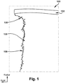
- FIG. 1 shows a side view of a turbine blade 100 with heavy water droplet erosion (WDE).
- WDE heavy water droplet erosion
- this type of erosion is dealt with by cutting blade 100 (usually a steam turbine blade) to remove the erosion, but not up to shroud 102 of blade 100.
- Leading edge 106 near shroud 102 remains damaged when using this type of repair.
- Other methods of WDE repair include replacing entire shroud 102. This type of repair method is expensive and time-consuming.
- a third method of WDE repair includes build-up welding. Build-up welding damages blade 100 with heat deformation, heat-induced stresses, and increased blade material brittleness, while failing to fortify blade 100 with a hardened material.
- the method includes removing all of the WDE, including leading edge 106 nearest shroud 102.
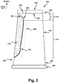
- an insert 112 also known as a coupon, may be welded to blade 100 to fill the area left by removing the WDE.
- the weld may not extend the entire length of insert 112.
- Insert 112 may be welded to blade 100 starting at a distance C away from shroud 102. The distance may be determined, for example, by the blade material and the amount of erosion removed from blade 100. Welding may cause the surrounding blade to be negatively affected by high heat.
- the weld line that attaches insert 112 to blade 100 may be far enough away from shroud 102 so that the thermally affected region 124 does not reach shroud 102.
- the region between insert 112 and blade 100 that is not welded may be called a weld-free region 116.
- Weld-free region 116 may extend from shroud 102 to weld region 114.
- insert 112 may be welded to blade 100 to fill the area left by removing the trailing edge 107 nearest platform 109 (embodiment not shown for brevity). Insert may be welded to blade 100 at a distance away from platform 109. The distance may be determined, for example, by the blade material and the amount of trailing edge 107 removed from blade 100. The weld may be far enough away from the platform 109 so that the thermally affected region does not reach platform 109.
- a gap 126 may be formed in weld-free region 116.
- the gap 126 may reduce interference between the blade 100 and the weld-free portion of insert 112. It should be understood that an omission of gap 126 does not depart from the present disclosure. However, omitting gap 126 may cause undesirable friction from vibration at the interface between blade 100 and the weld-free portion of insert 112.
- Gap 126 may also include a rounded portion 128 between shroud 102 and weld-free region 116. In one embodiment, rounded portion 128 may be formed at an interface between weld region 114 and weld-free region 116. Rounded portion 128 may assist in reducing stress concentrations at the interface between weld region 114 and weld-free region 116. In one embodiment, gap 126 may have a uniform width along the entire length of gap 126.
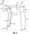
- insert 112 may include a thick region 118 near shroud 102.
- Thick region 118 may be thicker than the rest of insert 112, e.g., axially and/or circumferentially.
- Thick region 118 may be thicker than the original airfoil, e.g., axially and/or circumferentially.
- Thick region 118 may assist in extending the operating lifetime of the repaired blade 100 because this region, leading edge 106 nearest shroud 102, typically suffers from the highest WDE.
- the repaired blade 100 may be operable for significantly longer than the original blade.
- thick region 118 may be thicker than blade 100 in a circumferential direction, and may provide additional protection for gap 126 and the portion of the original blade adjacent to gap 126.
- Insert 112 may include a material that is more durable to WDE than the original airfoil.
- insert 112 may include a hardened material therein.
- the hardened material may be formed by flame hardening, high frequency hardening, induction hardening, laser hardening, or any other method of material hardening now know or later developed.
- insert 112 may be the same material as the original bade.
- insert 112 may be a hardened material of the original blade.
- Insert 112 may extend passed the original leading edge 106 of blade 100 in the axial direction for additional protection. Insert 112 may extend passed original leading edge 106 of blade 100 along the entire weld-free region 116 in the axial direction. As shown in FIG. 3 , in one embodiment, insert 112 may also or alternatively extend passed a base 120 of shroud 102 in the radial direction. In one embodiment, insert 112 may extend to an outermost surface 122 of shroud 102 in the radial direction. In another embodiment, shown in FIG. 4 , insert 112 may not extend passed base 120 of shroud 102 in the radial direction.
- insert 112 fits within an axial forward extent of shroud 102.
- insert 112 need not provide a leading edge 206 that is identical to leading edge 106, e.g., it may extend more forwardly in an axial direction in one or more portions thereof beyond an axial forward extent of shroud 102.
- a turbine blade 100 including a shroud 102 at a tip 104 of the blade 100 and a leading edge 106 extending between shroud 102 and a root 108 of blade 100 may include a cutout portion 110 extending at least along a portion of leading edge 106 of blade 100 nearest shroud 102. Cutout portion 110 may be formed by removing the eroded portion of blade 100. The dimensions and shape of cutout potion 110 may vary depending on the amount of erosion removed from blade 100.
- insert 112 may be shaped to mate with cutout portion 110 at weld region 114. Insert 112 may be welded to cutout portion 110 at weld region 114. Insert 112 may not be welded to cutout portion 110 at weld-free region 116.
- insert 112 may include a hardened material. Insert 112 may have an increased thickness nearest shroud 102, e.g., in the axial and/or circumferential direction. For example, a portion of insert 112 may extend beyond shroud 102 in an axial direction. A portion of insert 112 may extend beyond a base 120 of shroud 102 in a radial direction. A portion of insert 112 may extend to an outermost surface 122 of shroud 102 in a radial direction.
- weld region 114 may include a thermally affected zone 124, where the thermally affected zone 124 may not extend to shroud 102.
- Weld-free region 116 may include a gap 126 between insert 112 and cutout portion 110. Gap 126 may include a constant width along a length of gap 126.
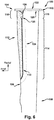
- gap 126 may include a rounded portion 128 between weld region 114 and weld-free region 116. In FIG. 2 , rounded portion 128 is convex relative to shroud 102; in FIG.
- rounded portion is concave relative to shroud 102, creating a larger gap 126 between shroud 102 and insert 112; and in FIG. 6 , rounded portion 128 more convex (bulbous) relative to shroud 102.
- rounded portion 128 may be defined by insert 112 at the interface between weld region 114 and weld-free region 116.
- insert 112 may be shaped to include rounded portion 128 at the interface between weld region 114 and weld-free region 116.
- gap 126 may terminate at rounded portion 128.
- the present disclosure describes one embodiment of a method for repairing a turbine blade 100 having a shroud 102 at a tip 104 of blade 100, the method includes removing an eroded portion 130 ( FIG. 1 ) of leading edge 106 of blade 100 to form cutout portion 110, the removed eroded portion 130 including at least a portion of leading edge 106 nearest shroud 102, to form cutout portion 110.
- the method may include welding insert 112 to cutout portion 110 only at a weld region 114, wherein the weld region 114 is located a distance C from shroud 102.
- the welding the insert 112 to the cutout portion 110 may include forming thermally affected zone 124 that does not extend to the shroud 102. Thermally affected zone 124 may be formed as a consequence of welding insert 112 to cutout portion 110 at weld region 114.
- the method may also include forming a gap 126 between insert 112 and cutout portion 110 at a weld-free region 116 nearest the shroud 102.
- the forming of gap 126 may include forming gap 126 with a constant width along a length of the gap 126.
- the forming of gap 126 may include forming a rounded portion 128 between weld region 114 and weld-free region 116.
- the forming of gap 126 may include forming insert 112 such that gap 126 is formed at weld-free region 116 when insert 112 is welded to cutout portion 110 at weld region 114.
- rounded portion 128 may be defined by insert 112 such that gap 126 terminates at rounded portion 128 at the interface between weld region 114 and weld-free region 116.
- the method may also include forming insert 112 such that insert 112 has an increased thickness at least nearest shroud 102.
- the method may also include forming insert 112 such that insert 112 extends beyond shroud 102 in an axial direction.
- the method may also include forming insert 112 such that insert 112 extends beyond a base 120 of shroud 102 in a radial direction.
- the method may also include forming the insert 112 such that insert 112 extends to an outermost surface 122 of the shroud 102 in a radial direction.
- Insert 112 may be made using any now known or later developed techniques such as but not limited to machining and/or additive manufacturing.
- the techniques described herein provide for easy welding, and avoid shroud deformation, increased material brittleness, and other heat damage that would result from close proximity to a weld. There is no welding of critical regions near the shroud and/or cover, yet the insert provides proven erosion resistance (with or without hardening), and is a cost effective repair method.
- Approximating language may be applied to modify any quantitative representation that could permissibly vary without resulting in a change in the basic function to which it is related. Accordingly, a value modified by a term or terms, such as “about,” “approximately” and “substantially,” are not to be limited to the precise value specified. In at least some instances, the approximating language may correspond to the precision of an instrument for measuring the value.
- range limitations may be combined and/or interchanged, such ranges are identified and include all the sub-ranges contained therein unless context or language indicates otherwise. "Approximately” as applied to a particular value of a range applies to both values, and unless otherwise dependent on the precision of the instrument measuring the value, may indicate +/-10% of the stated value(s).
Landscapes
- Engineering & Computer Science (AREA)
- Mechanical Engineering (AREA)
- General Engineering & Computer Science (AREA)
- Chemical & Material Sciences (AREA)
- Materials Engineering (AREA)
- Architecture (AREA)
- Turbine Rotor Nozzle Sealing (AREA)
Abstract
Description
- The disclosure relates generally to forming turbine blades, and more particularly, to a forming a turbine blade having an insert welded to an edge of the turbine blade.
- Steam turbine blades are affected by heavy water droplet erosion (WDE). Similarly, gas turbine blades are affected by corrosion. This disclosure relates to forming a blade having an insert welded to a leading edge and/or a trailing edge of an airfoil. This insert can be used to repair heavy erosion or corrosion with a reduced cost with respect to other methodologies with a lower risk of cracking.
- Current methods of repairing turbine blades have a number of disadvantages. For example, some current methods for repairing WDE fail to repair the leading edge section nearest the shroud. The leading edge nearest the shroud is typically the section of the airfoil that experiences the highest WDE. It is very important to maintain original material shapes and characteristics in this section of the blade. During a repair, a weld may be used to attach a replacement leading edge to the airfoil. The weld creates high temperatures in the blade material and the high temperatures can cause deformations and other undesirable changes in the shroud material, for example, causing the material to become brittle. Since welding near the shroud causes undesirable heat damage, conventional blade repair does not address the leading edge nearest the shroud.
- In examples that do address the leading edge of the airfoil nearest the shroud, the entire shroud is replaced. This type of repair method includes added costs of materials and machining.
- A first aspect of the disclosure provides a turbine blade. The turbine blade includes a shroud at a tip of the blade and an airfoil having a leading edge extending between the shroud and a root of the blade; a cutout portion extending at least along the leading edge of the airfoil nearest the shroud; an insert welded to the cutout portion at a weld region; and a weld-free region located between the insert and the cutout portion nearest the shroud.
- A second aspect of the disclosure provides a method for repairing a turbine blade having a shroud at a tip of the blade. The method includes removing a portion of a leading edge of an airfoil to form a cutout portion, the removed portion including at least a portion of the leading edge nearest the shroud; and welding an insert to the cutout portion only at a weld region, wherein the weld region is located a distance from the shroud.
- A third aspect of the disclosure provides a turbine blade. The turbine blade includes a platform at a root of the blade and an airfoil having a trailing edge extending between the platform and a tip of the blade; a cutout portion extending at least along the trailing edge of the airfoil nearest the platform; an insert welded to the cutout portion at a weld region; and a weld-free region located between the insert and the cutout portion nearest the platform.
- These and other features of this disclosure will be more readily understood from the following detailed description of the various aspects of the disclosure taken in conjunction with the accompanying drawings that depict various embodiments of the disclosure, in which:
-
FIG. 1 shows a side view of a turbine blade with heavy water droplet erosion (WDE). -
FIG. 2 shows a side view of a repaired turbine blade according to embodiments of the present disclosure. -
FIG. 3 shows a side view of a repaired turbine blade according to embodiments of the present disclosure. -
FIG. 4 shows a side view of a repaired turbine blade according to embodiments of the present disclosure. -
FIG. 5 shows a side view of a repaired turbine blade according to embodiments of the present disclosure. -
FIG. 6 shows a side view of a repaired turbine blade according to embodiments of the present disclosure. - As an initial matter, in order to clearly describe the current disclosure it will become necessary to select certain terminology when referring to and describing relevant directions of a turbine blade. When doing this, if possible, common industry terminology will be used and employed in a manner consistent with its accepted meaning. Unless otherwise stated, such terminology should be given a broad interpretation consistent with the context of the present application and the scope of the appended claims. Those of ordinary skill in the art will appreciate that often a particular component may be referred to using several different or overlapping terms. What may be described herein as being a single part may include and be referenced in another context as consisting of multiple components. Alternatively, what may be described herein as including multiple components may be referred to elsewhere as a single part.
- In addition, several descriptive terms may be used regularly herein, and it should prove helpful to define these terms at the onset of this section. These terms and their definitions, unless stated otherwise, are as follows. As used herein, "downstream" and "upstream" are terms that indicate a direction relative to the flow of a fluid, such as the working fluid through the turbine engine or, for example, the flow of air through the combustor or coolant through one of the turbine's component systems. The term "downstream" corresponds to the direction of flow of the fluid, and the term "upstream" refers to the direction opposite to the flow. The terms "forward" and "aft," without any further specificity, refer to directions, with "forward" referring to the front or compressor end of the engine, and "aft" referring to the rearward or turbine end of the engine. It is often required to describe parts that are at differing radial positions with regard to a center axis. The term "radial" refers to movement or position perpendicular to an axis. In cases such as this, if a first component resides closer to the axis than a second component, it will be stated herein that the first component is "radially inward" or "inboard" of the second component. If, on the other hand, the first component resides further from the axis than the second component, it may be stated herein that the first component is "radially outward" or "outboard" of the second component. The term "axial" refers to movement or position parallel to an axis, e.g., of the rotor of the turbine engine. Finally, the term "circumferential" refers to movement or position around an axis. It will be appreciated that such terms may be applied in relation to the center axis of the turbine.
- The present disclosure relates to a turbine blade having an insert welded to a leading edge and/or a trailing edge of the airfoil. For the sake or brevity, an example embodiment of a repaired turbine blade and a method of repairing a turbine blade that has WDE damage is described. However, it should be understood that the teachings of this disclosure are not limited to steam turbine blades with WDE. A person skilled in the art will recognize that the teachings of this disclosure may be applied to any turbine blade. For example, the teachings of this disclosure may be applied to a leading edge of a rotating blade or a trailing edge of a stationary blade. It should be understood that the teachings of this disclosure may be applied to steam turbine blades and gas turbine blades. It should also be understood that the teachings of this disclosure may be applied to an undamaged blade to preemptively strengthen the blade.
-
FIG. 1 shows a side view of aturbine blade 100 with heavy water droplet erosion (WDE). Typically, this type of erosion is dealt with by cutting blade 100 (usually a steam turbine blade) to remove the erosion, but not up toshroud 102 ofblade 100.Leading edge 106 nearshroud 102 remains damaged when using this type of repair. Other methods of WDE repair include replacingentire shroud 102. This type of repair method is expensive and time-consuming. A third method of WDE repair includes build-up welding. Build-upwelding damages blade 100 with heat deformation, heat-induced stresses, and increased blade material brittleness, while failing to fortifyblade 100 with a hardened material. - The present disclosure aims to describe a more cost-effective repair method. In one embodiment, the method includes removing all of the WDE, including leading
edge 106nearest shroud 102. As shown inFIG. 2 , aninsert 112, also known as a coupon, may be welded toblade 100 to fill the area left by removing the WDE. To prevent heat damage toshroud 102, the weld may not extend the entire length ofinsert 112.Insert 112 may be welded toblade 100 starting at a distance C away fromshroud 102. The distance may be determined, for example, by the blade material and the amount of erosion removed fromblade 100. Welding may cause the surrounding blade to be negatively affected by high heat. The weld line that attachesinsert 112 to blade 100 (weld region 114) may be far enough away fromshroud 102 so that the thermally affectedregion 124 does not reachshroud 102. The region betweeninsert 112 andblade 100 that is not welded may be called a weld-free region 116. Weld-free region 116 may extend fromshroud 102 toweld region 114. - It will be recognized by a person skilled in the art that these aspects of the disclosure may be applied near a
platform 109 of the blade instead ofshroud 102 in an alternative embodiment. In an example embodiment, the trailingedge 107nearest platform 109 may be removed.Insert 112 may be welded toblade 100 to fill the area left by removing the trailingedge 107 nearest platform 109 (embodiment not shown for brevity). Insert may be welded toblade 100 at a distance away fromplatform 109. The distance may be determined, for example, by the blade material and the amount of trailingedge 107 removed fromblade 100. The weld may be far enough away from theplatform 109 so that the thermally affected region does not reachplatform 109. - As shown in
FIG. 2 , agap 126 may be formed in weld-free region 116. Thegap 126 may reduce interference between theblade 100 and the weld-free portion ofinsert 112. It should be understood that an omission ofgap 126 does not depart from the present disclosure. However, omittinggap 126 may cause undesirable friction from vibration at the interface betweenblade 100 and the weld-free portion ofinsert 112.Gap 126 may also include arounded portion 128 betweenshroud 102 and weld-free region 116. In one embodiment,rounded portion 128 may be formed at an interface betweenweld region 114 and weld-free region 116.Rounded portion 128 may assist in reducing stress concentrations at the interface betweenweld region 114 and weld-free region 116. In one embodiment,gap 126 may have a uniform width along the entire length ofgap 126. - As shown in
FIG. 3 , insert 112 may include athick region 118 nearshroud 102.Thick region 118 may be thicker than the rest ofinsert 112, e.g., axially and/or circumferentially.Thick region 118 may be thicker than the original airfoil, e.g., axially and/or circumferentially.Thick region 118 may assist in extending the operating lifetime of the repairedblade 100 because this region, leadingedge 106nearest shroud 102, typically suffers from the highest WDE. The repairedblade 100 may be operable for significantly longer than the original blade. In one embodiment,thick region 118 may be thicker thanblade 100 in a circumferential direction, and may provide additional protection forgap 126 and the portion of the original blade adjacent to gap 126. -
Insert 112 may include a material that is more durable to WDE than the original airfoil. For example, insert 112 may include a hardened material therein. The hardened material may be formed by flame hardening, high frequency hardening, induction hardening, laser hardening, or any other method of material hardening now know or later developed. In another embodiment, insert 112 may be the same material as the original bade. For example, insert 112 may be a hardened material of the original blade. -
Insert 112 may extend passed the originalleading edge 106 ofblade 100 in the axial direction for additional protection.Insert 112 may extend passed originalleading edge 106 ofblade 100 along the entire weld-free region 116 in the axial direction. As shown inFIG. 3 , in one embodiment, insert 112 may also or alternatively extend passed abase 120 ofshroud 102 in the radial direction. In one embodiment, insert 112 may extend to anoutermost surface 122 ofshroud 102 in the radial direction. In another embodiment, shown inFIG. 4 , insert 112 may not extend passedbase 120 ofshroud 102 in the radial direction. - In
FIG. 2 , insert 112 fits within an axial forward extent ofshroud 102. In another embodiment, as shown inFIGS. 3-5 , insert 112 need not provide aleading edge 206 that is identical toleading edge 106, e.g., it may extend more forwardly in an axial direction in one or more portions thereof beyond an axial forward extent ofshroud 102. - As shown in
FIGS. 2-6 , aturbine blade 100 including ashroud 102 at atip 104 of theblade 100 and aleading edge 106 extending betweenshroud 102 and aroot 108 ofblade 100 may include acutout portion 110 extending at least along a portion of leadingedge 106 ofblade 100nearest shroud 102.Cutout portion 110 may be formed by removing the eroded portion ofblade 100. The dimensions and shape ofcutout potion 110 may vary depending on the amount of erosion removed fromblade 100. In one embodiment, insert 112 may be shaped to mate withcutout portion 110 atweld region 114.Insert 112 may be welded tocutout portion 110 atweld region 114.Insert 112 may not be welded tocutout portion 110 at weld-free region 116. - As noted, insert 112 may include a hardened material.
Insert 112 may have an increased thickness nearestshroud 102, e.g., in the axial and/or circumferential direction. For example, a portion ofinsert 112 may extend beyondshroud 102 in an axial direction. A portion ofinsert 112 may extend beyond abase 120 ofshroud 102 in a radial direction. A portion ofinsert 112 may extend to anoutermost surface 122 ofshroud 102 in a radial direction. - As shown in
FIGS. 2-6 ,weld region 114 may include a thermally affectedzone 124, where the thermally affectedzone 124 may not extend toshroud 102. Weld-free region 116 may include agap 126 betweeninsert 112 andcutout portion 110.Gap 126 may include a constant width along a length ofgap 126. As shown inFIGS. 2 ,5 and6 ,gap 126 may include arounded portion 128 betweenweld region 114 and weld-free region 116. InFIG. 2 ,rounded portion 128 is convex relative toshroud 102; inFIG. 5 , rounded portion is concave relative toshroud 102, creating alarger gap 126 betweenshroud 102 and insert 112; and inFIG. 6 ,rounded portion 128 more convex (bulbous) relative toshroud 102. In one embodiment, shown inFIG. 6 for example,rounded portion 128 may be defined byinsert 112 at the interface betweenweld region 114 and weld-free region 116. In other words, insert 112 may be shaped to includerounded portion 128 at the interface betweenweld region 114 and weld-free region 116. In such an embodiment,gap 126 may terminate atrounded portion 128. - The present disclosure describes one embodiment of a method for repairing a
turbine blade 100 having ashroud 102 at atip 104 ofblade 100, the method includes removing an eroded portion 130 (FIG. 1 ) of leadingedge 106 ofblade 100 to formcutout portion 110, the removed erodedportion 130 including at least a portion of leadingedge 106nearest shroud 102, to formcutout portion 110. The method may includewelding insert 112 tocutout portion 110 only at aweld region 114, wherein theweld region 114 is located a distance C fromshroud 102. - The welding the
insert 112 to thecutout portion 110 may include forming thermally affectedzone 124 that does not extend to theshroud 102. Thermally affectedzone 124 may be formed as a consequence ofwelding insert 112 tocutout portion 110 atweld region 114. The method may also include forming agap 126 betweeninsert 112 andcutout portion 110 at a weld-free region 116 nearest theshroud 102. The forming ofgap 126 may include forminggap 126 with a constant width along a length of thegap 126. The forming ofgap 126 may include forming arounded portion 128 betweenweld region 114 and weld-free region 116. The forming ofgap 126 may include forminginsert 112 such thatgap 126 is formed at weld-free region 116 wheninsert 112 is welded tocutout portion 110 atweld region 114. As noted,rounded portion 128 may be defined byinsert 112 such thatgap 126 terminates atrounded portion 128 at the interface betweenweld region 114 and weld-free region 116. - The method may also include forming
insert 112 such thatinsert 112 has an increased thickness at leastnearest shroud 102. The method may also include forminginsert 112 such thatinsert 112 extends beyondshroud 102 in an axial direction. The method may also include forminginsert 112 such thatinsert 112 extends beyond abase 120 ofshroud 102 in a radial direction. The method may also include forming theinsert 112 such thatinsert 112 extends to anoutermost surface 122 of theshroud 102 in a radial direction.Insert 112 may be made using any now known or later developed techniques such as but not limited to machining and/or additive manufacturing. - The techniques described herein provide for easy welding, and avoid shroud deformation, increased material brittleness, and other heat damage that would result from close proximity to a weld. There is no welding of critical regions near the shroud and/or cover, yet the insert provides proven erosion resistance (with or without hardening), and is a cost effective repair method.
- While embodiments of the disclosure have been described relative to repair of WDE in steam turbine blades, it is emphasized that the techniques may be equally applicable to other forms of erosion in turbine blades.
- The terminology used herein is for the purpose of describing particular embodiments only and is not intended to be limiting of the disclosure. As used herein, the singular forms "a", "an" and "the" are intended to include the plural forms as well, unless the context clearly indicates otherwise. It will be further understood that the terms "comprises" and/or "comprising," when used in this specification, specify the presence of stated features, integers, steps, operations, elements, and/or components, but do not preclude the presence or addition of one or more other features, integers, steps, operations, elements, components, and/or groups thereof. "Optional" or "optionally" means that the subsequently described event or circumstance may or may not occur, and that the description includes instances where the event occurs and instances where it does not.
- Approximating language, as used herein throughout the specification and claims, may be applied to modify any quantitative representation that could permissibly vary without resulting in a change in the basic function to which it is related. Accordingly, a value modified by a term or terms, such as "about," "approximately" and "substantially," are not to be limited to the precise value specified. In at least some instances, the approximating language may correspond to the precision of an instrument for measuring the value. Here and throughout the specification and claims, range limitations may be combined and/or interchanged, such ranges are identified and include all the sub-ranges contained therein unless context or language indicates otherwise. "Approximately" as applied to a particular value of a range applies to both values, and unless otherwise dependent on the precision of the instrument measuring the value, may indicate +/-10% of the stated value(s).
- The corresponding structures, materials, acts, and equivalents of all means or step plus function elements in the claims below are intended to include any structure, material, or act for performing the function in combination with other claimed elements as specifically claimed. The description of the present disclosure has been presented for purposes of illustration and description, but is not intended to be exhaustive or limited to the disclosure in the form disclosed. Many modifications and variations will be apparent to those of ordinary skill in the art without departing from the scope and spirit of the disclosure. The embodiment was chosen and described in order to best explain the principles of the disclosure and the practical application, and to enable others of ordinary skill in the art to understand the disclosure for various embodiments with various modifications as are suited to the particular use contemplated.
Claims (15)
- A turbine blade (100) comprising:a shroud (102) at a tip (104) of the blade (100) and an airfoil having a leading edge (106) extending between the shroud (102) and a root (108) of the blade (100);a cutout portion (110) extending at least along the leading edge (106) of the airfoil nearest the shroud (102);an insert (112) welded to the cutout portion (110) at a weld region (114); anda weld-free region (116) located between the insert (112) and the cutout portion (110) nearest the shroud (102).
- The turbine blade of (100) claim 1, wherein the insert (112) is a hardened material.
- The turbine blade (100) of claim 1 or claim 2, wherein the insert (112) has an increased thickness nearest the shroud (102).
- The turbine blade (100) of any preceding claim, wherein a portion of the insert (112) extends beyond the shroud (102) in an axial direction.
- The turbine blade (100) of any preceding claim, wherein a portion of the insert (112) extends beyond a base (120) of the shroud (102) in a radial direction.
- The turbine blade (100) of any preceding claim, wherein a portion of the insert (112) extends to an outermost surface (122) of the shroud (102) in a radial direction.
- The turbine blade (100) of any preceding claim, wherein the weld region (114) includes a thermally affected zone (124), and wherein the thermally affected zone (124) does not extend to the shroud (102).
- The turbine blade (100) of any preceding claim, wherein the weld-free region (116) between the insert (112) and the cutout portion (110) includes a gap (126).
- A method for forming a turbine blade (100) having a shroud (102) at a tip (104) of the blade (100), the method comprising:removing a portion of a leading edge (106) of an airfoil to form a cutout portion (110), the removed portion including at least a portion of the leading edge (106) nearest the shroud (102); andwelding an insert (112) to the cutout portion (110) only at a weld region (114), wherein the weld region (114) is located a distance from the shroud (102).
- The method of claim 9, wherein the welding the insert (112) to the cutout portion (110) includes forming a thermally affected zone (124) that does not extend to the shroud (102).
- The method of claim 9 or claim 10, further comprising forming a gap (126) between the insert (112) and the cutout portion (110) at a weld-free region (116) nearest the shroud (102).
- The method of claim 9, further comprising forming the insert (112) such that the insert (112) has an increased thickness nearest the shroud (102).
- The method of claim 11, further comprising forming the insert (112) such that the insert (112) extends beyond the shroud (102) in an axial direction.
- The method of claim 9, further comprising forming the insert (112) such that the insert (112) extends beyond a base (120) of the shroud (102) in a radial direction.
- A turbine blade (100) comprising:a platform (109) at a root (108) of the blade (100) and an airfoil having a trailing edge (107) extending between the platform (109) and a tip (104) of the blade (100);a cutout portion (110) extending at least along the trailing edge (107) of the airfoil nearest the platform (109);an insert (112) welded to the cutout portion (110) at a weld region (114); anda weld-free region (116) located between the insert (112) and the cutout portion (110) nearest the platform (109).
Applications Claiming Priority (2)
| Application Number | Priority Date | Filing Date | Title |
|---|---|---|---|
| US201662407287P | 2016-10-12 | 2016-10-12 | |
| US15/377,060 US10260349B2 (en) | 2016-10-12 | 2016-12-13 | Tubine blade and related method of forming |
Publications (2)
| Publication Number | Publication Date |
|---|---|
| EP3321473A1 true EP3321473A1 (en) | 2018-05-16 |
| EP3321473B1 EP3321473B1 (en) | 2019-04-03 |
Family
ID=61829989
Family Applications (1)
| Application Number | Title | Priority Date | Filing Date |
|---|---|---|---|
| EP17195941.4A Active EP3321473B1 (en) | 2016-10-12 | 2017-10-11 | Tubine blade and related method of forming |
Country Status (3)
| Country | Link |
|---|---|
| US (1) | US10260349B2 (en) |
| EP (1) | EP3321473B1 (en) |
| CN (1) | CN108252746B (en) |
Cited By (1)
| Publication number | Priority date | Publication date | Assignee | Title |
|---|---|---|---|---|
| DE102020101472A1 (en) * | 2020-01-22 | 2021-02-11 | Helmholtz-Zentrum Geesthacht Zentrum für Material- und Küstenforschung GmbH | Method and set of replacement parts for repairing a titanium aluminide low pressure turbine blade |
Families Citing this family (4)
| Publication number | Priority date | Publication date | Assignee | Title |
|---|---|---|---|---|
| JP6278191B2 (en) * | 2014-04-07 | 2018-02-14 | 株式会社Ihi | COMPOSITE WING AND METHOD FOR PRODUCING COMPOSITE WING |
| US10907609B2 (en) * | 2014-07-15 | 2021-02-02 | Ge Renewable Technologies | Apparatus and method for modifying a geometry of a turbine part |
| CA2857297C (en) * | 2014-07-21 | 2021-08-17 | Alstom Renewable Technologies | Apparatus and method for modifying a geometry of a turbine part |
| EP4530444A3 (en) * | 2023-09-28 | 2025-05-07 | General Electric Technology GmbH | Exhaust diffuser assembly having stress-relief openings at a split-line |
Citations (4)
| Publication number | Priority date | Publication date | Assignee | Title |
|---|---|---|---|---|
| US3650635A (en) * | 1970-03-09 | 1972-03-21 | Chromalloy American Corp | Turbine vanes |
| EP2317075A2 (en) * | 2009-10-30 | 2011-05-04 | Alstom Technology Ltd | Method for repairing a gas turbine component |
| EP2781691A1 (en) * | 2013-03-19 | 2014-09-24 | Alstom Technology Ltd | Method for reconditioning a hot gas path part of a gas turbine |
| EP2949418A1 (en) * | 2014-05-30 | 2015-12-02 | Alstom Technology Ltd. | Method for repairing a turbine blade tip |
Family Cites Families (11)
| Publication number | Priority date | Publication date | Assignee | Title |
|---|---|---|---|---|
| US6785961B1 (en) * | 1999-11-12 | 2004-09-07 | General Electric Corporation | Turbine nozzle segment and method of repairing same |
| US6508000B2 (en) * | 2001-02-08 | 2003-01-21 | Siemens Westinghouse Power Corporation | Transient liquid phase bonding repair for advanced turbine blades and vanes |
| US6575702B2 (en) * | 2001-10-22 | 2003-06-10 | General Electric Company | Airfoils with improved strength and manufacture and repair thereof |
| US20070079507A1 (en) * | 2005-10-12 | 2007-04-12 | Kenny Cheng | Blade shroud repair |
| US7780419B1 (en) * | 2007-03-06 | 2010-08-24 | Florida Turbine Technologies, Inc. | Replaceable leading edge insert for an IBR |
| FR2923741B1 (en) * | 2007-11-19 | 2010-05-14 | Snecma Services | PROCESS FOR REPAIRING A THERMOMECHANICAL PART BY A HIGH ENERGY BEAM |
| US8539659B2 (en) * | 2008-04-23 | 2013-09-24 | United Technologies Corporation | Method of repairing an article |
| JP5411120B2 (en) | 2010-12-27 | 2014-02-12 | 株式会社日立製作所 | Titanium alloy turbine blade |
| FR2983757B1 (en) * | 2011-12-07 | 2014-09-12 | Snecma | PROCESS FOR REFORMING A TURBOMACHINE BLADE COMPRISING AT LEAST ONE ZONE DEFORMEE BY GRASPING |
| US9452474B2 (en) * | 2014-05-09 | 2016-09-27 | United Technologies Corporation | Method for forming a directionally solidified replacement body for a component using additive manufacturing |
| CN205591967U (en) * | 2016-05-03 | 2016-09-21 | 无锡润和叶片制造有限公司 | High, medium and low pressure of 600MW steam turbine blade of brazing |
-
2016
- 2016-12-13 US US15/377,060 patent/US10260349B2/en active Active
-
2017
- 2017-10-11 EP EP17195941.4A patent/EP3321473B1/en active Active
- 2017-10-12 CN CN201710947207.3A patent/CN108252746B/en active Active
Patent Citations (4)
| Publication number | Priority date | Publication date | Assignee | Title |
|---|---|---|---|---|
| US3650635A (en) * | 1970-03-09 | 1972-03-21 | Chromalloy American Corp | Turbine vanes |
| EP2317075A2 (en) * | 2009-10-30 | 2011-05-04 | Alstom Technology Ltd | Method for repairing a gas turbine component |
| EP2781691A1 (en) * | 2013-03-19 | 2014-09-24 | Alstom Technology Ltd | Method for reconditioning a hot gas path part of a gas turbine |
| EP2949418A1 (en) * | 2014-05-30 | 2015-12-02 | Alstom Technology Ltd. | Method for repairing a turbine blade tip |
Cited By (1)
| Publication number | Priority date | Publication date | Assignee | Title |
|---|---|---|---|---|
| DE102020101472A1 (en) * | 2020-01-22 | 2021-02-11 | Helmholtz-Zentrum Geesthacht Zentrum für Material- und Küstenforschung GmbH | Method and set of replacement parts for repairing a titanium aluminide low pressure turbine blade |
Also Published As
| Publication number | Publication date |
|---|---|
| US20180100397A1 (en) | 2018-04-12 |
| EP3321473B1 (en) | 2019-04-03 |
| CN108252746A (en) | 2018-07-06 |
| US10260349B2 (en) | 2019-04-16 |
| CN108252746B (en) | 2021-12-07 |
Similar Documents
| Publication | Publication Date | Title |
|---|---|---|
| EP3321473B1 (en) | Tubine blade and related method of forming | |
| JP6385949B2 (en) | Method of friction welding blades to a turbine engine rotor disk; corresponding integrated blade disk | |
| US7959409B2 (en) | Repaired vane assemblies and methods of repairing vane assemblies | |
| EP1138431B2 (en) | Method of repairing an airfoil | |
| EP1302627B1 (en) | Gas turbine engine compressor blade restoration | |
| US20090314823A1 (en) | Method of friction welding | |
| EP2586562A2 (en) | Methods for repairing turbine blade tips | |
| JP2008045541A (en) | Method of repairing shroud of turbine blades | |
| EP2484867A2 (en) | Rotating component of a turbine engine | |
| EP2998060B1 (en) | Method of replacing damaged blade | |
| CN102548682B (en) | Titanium blades of compressor repaired by cold pressing | |
| US10875131B2 (en) | Repair or remanufacture of blade platform for a gas turbine engine | |
| JP4588318B2 (en) | Method for replacing a portion of a turbine shroud support | |
| EP3318364A1 (en) | Threaded coupon for repair of superalloy part | |
| EP3441181A1 (en) | Methods for treating components formed from equiaxed material or directionally solidified structure, and treated components | |
| JP2005133725A (en) | Gas turbine compressor rotor blade repair method | |
| EP2093375A2 (en) | Method of repair for cantilevered stators | |
| EP3338938B1 (en) | Method for modifying a shroud and blade | |
| EP1712325A1 (en) | Overlay for repairing spline and seal teeth of a mated component comprising a tube and internal slines | |
| CN107073622B (en) | Method of repairing the upstream track of the turbine casing of a turbine engine | |
| US20160001390A1 (en) | System and method low heat weld | |
| WO2019212533A1 (en) | Hybrid manufacturing and repair of components | |
| US11480061B2 (en) | Method for replacing metal airfoil with ceramic airfoil, and related turbomachine blade | |
| JP2009543968A (en) | Repair method for jet engine guide blade segment | |
| CN109219688B (en) | Turbine engine mid-case with seal member at arm/shroud interface |
Legal Events
| Date | Code | Title | Description |
|---|---|---|---|
| PUAI | Public reference made under article 153(3) epc to a published international application that has entered the european phase |
Free format text: ORIGINAL CODE: 0009012 |
|
| STAA | Information on the status of an ep patent application or granted ep patent |
Free format text: STATUS: THE APPLICATION HAS BEEN PUBLISHED |
|
| AK | Designated contracting states |
Kind code of ref document: A1 Designated state(s): AL AT BE BG CH CY CZ DE DK EE ES FI FR GB GR HR HU IE IS IT LI LT LU LV MC MK MT NL NO PL PT RO RS SE SI SK SM TR |
|
| AX | Request for extension of the european patent |
Extension state: BA ME |
|
| STAA | Information on the status of an ep patent application or granted ep patent |
Free format text: STATUS: REQUEST FOR EXAMINATION WAS MADE |
|
| 17P | Request for examination filed |
Effective date: 20181116 |
|
| RBV | Designated contracting states (corrected) |
Designated state(s): AL AT BE BG CH CY CZ DE DK EE ES FI FR GB GR HR HU IE IS IT LI LT LU LV MC MK MT NL NO PL PT RO RS SE SI SK SM TR |
|
| GRAP | Despatch of communication of intention to grant a patent |
Free format text: ORIGINAL CODE: EPIDOSNIGR1 |
|
| STAA | Information on the status of an ep patent application or granted ep patent |
Free format text: STATUS: GRANT OF PATENT IS INTENDED |
|
| RIC1 | Information provided on ipc code assigned before grant |
Ipc: F01D 5/28 20060101ALI20181211BHEP Ipc: F01D 5/22 20060101AFI20181211BHEP |
|
| INTG | Intention to grant announced |
Effective date: 20190109 |
|
| GRAS | Grant fee paid |
Free format text: ORIGINAL CODE: EPIDOSNIGR3 |
|
| GRAA | (expected) grant |
Free format text: ORIGINAL CODE: 0009210 |
|
| STAA | Information on the status of an ep patent application or granted ep patent |
Free format text: STATUS: THE PATENT HAS BEEN GRANTED |
|
| AK | Designated contracting states |
Kind code of ref document: B1 Designated state(s): AL AT BE BG CH CY CZ DE DK EE ES FI FR GB GR HR HU IE IS IT LI LT LU LV MC MK MT NL NO PL PT RO RS SE SI SK SM TR |
|
| REG | Reference to a national code |
Ref country code: GB Ref legal event code: FG4D |
|
| REG | Reference to a national code |
Ref country code: CH Ref legal event code: EP Ref country code: AT Ref legal event code: REF Ref document number: 1115980 Country of ref document: AT Kind code of ref document: T Effective date: 20190415 |
|
| REG | Reference to a national code |
Ref country code: IE Ref legal event code: FG4D |
|
| REG | Reference to a national code |
Ref country code: DE Ref legal event code: R096 Ref document number: 602017003080 Country of ref document: DE |
|
| REG | Reference to a national code |
Ref country code: CH Ref legal event code: NV Representative=s name: FREIGUTPARTNERS IP LAW FIRM DR. ROLF DITTMANN, CH |
|
| REG | Reference to a national code |
Ref country code: NL Ref legal event code: MP Effective date: 20190403 |
|
| REG | Reference to a national code |
Ref country code: LT Ref legal event code: MG4D |
|
| REG | Reference to a national code |
Ref country code: AT Ref legal event code: MK05 Ref document number: 1115980 Country of ref document: AT Kind code of ref document: T Effective date: 20190403 |
|
| PG25 | Lapsed in a contracting state [announced via postgrant information from national office to epo] |
Ref country code: NL Free format text: LAPSE BECAUSE OF FAILURE TO SUBMIT A TRANSLATION OF THE DESCRIPTION OR TO PAY THE FEE WITHIN THE PRESCRIBED TIME-LIMIT Effective date: 20190403 |
|
| PG25 | Lapsed in a contracting state [announced via postgrant information from national office to epo] |
Ref country code: SE Free format text: LAPSE BECAUSE OF FAILURE TO SUBMIT A TRANSLATION OF THE DESCRIPTION OR TO PAY THE FEE WITHIN THE PRESCRIBED TIME-LIMIT Effective date: 20190403 Ref country code: HR Free format text: LAPSE BECAUSE OF FAILURE TO SUBMIT A TRANSLATION OF THE DESCRIPTION OR TO PAY THE FEE WITHIN THE PRESCRIBED TIME-LIMIT Effective date: 20190403 Ref country code: LT Free format text: LAPSE BECAUSE OF FAILURE TO SUBMIT A TRANSLATION OF THE DESCRIPTION OR TO PAY THE FEE WITHIN THE PRESCRIBED TIME-LIMIT Effective date: 20190403 Ref country code: CZ Free format text: LAPSE BECAUSE OF FAILURE TO SUBMIT A TRANSLATION OF THE DESCRIPTION OR TO PAY THE FEE WITHIN THE PRESCRIBED TIME-LIMIT Effective date: 20190403 Ref country code: ES Free format text: LAPSE BECAUSE OF FAILURE TO SUBMIT A TRANSLATION OF THE DESCRIPTION OR TO PAY THE FEE WITHIN THE PRESCRIBED TIME-LIMIT Effective date: 20190403 Ref country code: NO Free format text: LAPSE BECAUSE OF FAILURE TO SUBMIT A TRANSLATION OF THE DESCRIPTION OR TO PAY THE FEE WITHIN THE PRESCRIBED TIME-LIMIT Effective date: 20190703 Ref country code: PT Free format text: LAPSE BECAUSE OF FAILURE TO SUBMIT A TRANSLATION OF THE DESCRIPTION OR TO PAY THE FEE WITHIN THE PRESCRIBED TIME-LIMIT Effective date: 20190803 Ref country code: FI Free format text: LAPSE BECAUSE OF FAILURE TO SUBMIT A TRANSLATION OF THE DESCRIPTION OR TO PAY THE FEE WITHIN THE PRESCRIBED TIME-LIMIT Effective date: 20190403 Ref country code: AL Free format text: LAPSE BECAUSE OF FAILURE TO SUBMIT A TRANSLATION OF THE DESCRIPTION OR TO PAY THE FEE WITHIN THE PRESCRIBED TIME-LIMIT Effective date: 20190403 |
|
| PG25 | Lapsed in a contracting state [announced via postgrant information from national office to epo] |
Ref country code: RS Free format text: LAPSE BECAUSE OF FAILURE TO SUBMIT A TRANSLATION OF THE DESCRIPTION OR TO PAY THE FEE WITHIN THE PRESCRIBED TIME-LIMIT Effective date: 20190403 Ref country code: LV Free format text: LAPSE BECAUSE OF FAILURE TO SUBMIT A TRANSLATION OF THE DESCRIPTION OR TO PAY THE FEE WITHIN THE PRESCRIBED TIME-LIMIT Effective date: 20190403 Ref country code: PL Free format text: LAPSE BECAUSE OF FAILURE TO SUBMIT A TRANSLATION OF THE DESCRIPTION OR TO PAY THE FEE WITHIN THE PRESCRIBED TIME-LIMIT Effective date: 20190403 Ref country code: GR Free format text: LAPSE BECAUSE OF FAILURE TO SUBMIT A TRANSLATION OF THE DESCRIPTION OR TO PAY THE FEE WITHIN THE PRESCRIBED TIME-LIMIT Effective date: 20190704 Ref country code: BG Free format text: LAPSE BECAUSE OF FAILURE TO SUBMIT A TRANSLATION OF THE DESCRIPTION OR TO PAY THE FEE WITHIN THE PRESCRIBED TIME-LIMIT Effective date: 20190703 |
|
| PG25 | Lapsed in a contracting state [announced via postgrant information from national office to epo] |
Ref country code: AT Free format text: LAPSE BECAUSE OF FAILURE TO SUBMIT A TRANSLATION OF THE DESCRIPTION OR TO PAY THE FEE WITHIN THE PRESCRIBED TIME-LIMIT Effective date: 20190403 Ref country code: IS Free format text: LAPSE BECAUSE OF FAILURE TO SUBMIT A TRANSLATION OF THE DESCRIPTION OR TO PAY THE FEE WITHIN THE PRESCRIBED TIME-LIMIT Effective date: 20190803 |
|
| REG | Reference to a national code |
Ref country code: DE Ref legal event code: R097 Ref document number: 602017003080 Country of ref document: DE |
|
| PG25 | Lapsed in a contracting state [announced via postgrant information from national office to epo] |
Ref country code: DK Free format text: LAPSE BECAUSE OF FAILURE TO SUBMIT A TRANSLATION OF THE DESCRIPTION OR TO PAY THE FEE WITHIN THE PRESCRIBED TIME-LIMIT Effective date: 20190403 Ref country code: SK Free format text: LAPSE BECAUSE OF FAILURE TO SUBMIT A TRANSLATION OF THE DESCRIPTION OR TO PAY THE FEE WITHIN THE PRESCRIBED TIME-LIMIT Effective date: 20190403 Ref country code: RO Free format text: LAPSE BECAUSE OF FAILURE TO SUBMIT A TRANSLATION OF THE DESCRIPTION OR TO PAY THE FEE WITHIN THE PRESCRIBED TIME-LIMIT Effective date: 20190403 Ref country code: EE Free format text: LAPSE BECAUSE OF FAILURE TO SUBMIT A TRANSLATION OF THE DESCRIPTION OR TO PAY THE FEE WITHIN THE PRESCRIBED TIME-LIMIT Effective date: 20190403 |
|
| PLBE | No opposition filed within time limit |
Free format text: ORIGINAL CODE: 0009261 |
|
| STAA | Information on the status of an ep patent application or granted ep patent |
Free format text: STATUS: NO OPPOSITION FILED WITHIN TIME LIMIT |
|
| PG25 | Lapsed in a contracting state [announced via postgrant information from national office to epo] |
Ref country code: SM Free format text: LAPSE BECAUSE OF FAILURE TO SUBMIT A TRANSLATION OF THE DESCRIPTION OR TO PAY THE FEE WITHIN THE PRESCRIBED TIME-LIMIT Effective date: 20190403 Ref country code: IT Free format text: LAPSE BECAUSE OF FAILURE TO SUBMIT A TRANSLATION OF THE DESCRIPTION OR TO PAY THE FEE WITHIN THE PRESCRIBED TIME-LIMIT Effective date: 20190403 |
|
| 26N | No opposition filed |
Effective date: 20200106 |
|
| PG25 | Lapsed in a contracting state [announced via postgrant information from national office to epo] |
Ref country code: TR Free format text: LAPSE BECAUSE OF FAILURE TO SUBMIT A TRANSLATION OF THE DESCRIPTION OR TO PAY THE FEE WITHIN THE PRESCRIBED TIME-LIMIT Effective date: 20190403 |
|
| PG25 | Lapsed in a contracting state [announced via postgrant information from national office to epo] |
Ref country code: MC Free format text: LAPSE BECAUSE OF FAILURE TO SUBMIT A TRANSLATION OF THE DESCRIPTION OR TO PAY THE FEE WITHIN THE PRESCRIBED TIME-LIMIT Effective date: 20190403 Ref country code: SI Free format text: LAPSE BECAUSE OF FAILURE TO SUBMIT A TRANSLATION OF THE DESCRIPTION OR TO PAY THE FEE WITHIN THE PRESCRIBED TIME-LIMIT Effective date: 20190403 |
|
| PG25 | Lapsed in a contracting state [announced via postgrant information from national office to epo] |
Ref country code: LU Free format text: LAPSE BECAUSE OF NON-PAYMENT OF DUE FEES Effective date: 20191011 |
|
| REG | Reference to a national code |
Ref country code: BE Ref legal event code: MM Effective date: 20191031 |
|
| PG25 | Lapsed in a contracting state [announced via postgrant information from national office to epo] |
Ref country code: BE Free format text: LAPSE BECAUSE OF NON-PAYMENT OF DUE FEES Effective date: 20191031 |
|
| PG25 | Lapsed in a contracting state [announced via postgrant information from national office to epo] |
Ref country code: IE Free format text: LAPSE BECAUSE OF NON-PAYMENT OF DUE FEES Effective date: 20191011 Ref country code: FR Free format text: LAPSE BECAUSE OF NON-PAYMENT OF DUE FEES Effective date: 20191031 |
|
| PG25 | Lapsed in a contracting state [announced via postgrant information from national office to epo] |
Ref country code: CY Free format text: LAPSE BECAUSE OF FAILURE TO SUBMIT A TRANSLATION OF THE DESCRIPTION OR TO PAY THE FEE WITHIN THE PRESCRIBED TIME-LIMIT Effective date: 20190403 |
|
| PG25 | Lapsed in a contracting state [announced via postgrant information from national office to epo] |
Ref country code: HU Free format text: LAPSE BECAUSE OF FAILURE TO SUBMIT A TRANSLATION OF THE DESCRIPTION OR TO PAY THE FEE WITHIN THE PRESCRIBED TIME-LIMIT; INVALID AB INITIO Effective date: 20171011 Ref country code: MT Free format text: LAPSE BECAUSE OF FAILURE TO SUBMIT A TRANSLATION OF THE DESCRIPTION OR TO PAY THE FEE WITHIN THE PRESCRIBED TIME-LIMIT Effective date: 20190403 |
|
| GBPC | Gb: european patent ceased through non-payment of renewal fee |
Effective date: 20211011 |
|
| PG25 | Lapsed in a contracting state [announced via postgrant information from national office to epo] |
Ref country code: MK Free format text: LAPSE BECAUSE OF FAILURE TO SUBMIT A TRANSLATION OF THE DESCRIPTION OR TO PAY THE FEE WITHIN THE PRESCRIBED TIME-LIMIT Effective date: 20190403 |
|
| PG25 | Lapsed in a contracting state [announced via postgrant information from national office to epo] |
Ref country code: GB Free format text: LAPSE BECAUSE OF NON-PAYMENT OF DUE FEES Effective date: 20211011 |
|
| P01 | Opt-out of the competence of the unified patent court (upc) registered |
Effective date: 20230523 |
|
| REG | Reference to a national code |
Ref country code: DE Ref legal event code: R081 Ref document number: 602017003080 Country of ref document: DE Owner name: ARABELLE SOLUTIONS FRANCE, FR Free format text: FORMER OWNER: GENERAL ELECTRIC COMPANY, SCHENECTADY, NY, US Ref country code: DE Ref legal event code: R081 Ref document number: 602017003080 Country of ref document: DE Owner name: ARABELLE TECHNOLOGIES, FR Free format text: FORMER OWNER: GENERAL ELECTRIC COMPANY, SCHENECTADY, NY, US Ref country code: DE Ref legal event code: R082 Ref document number: 602017003080 Country of ref document: DE Ref country code: DE Ref legal event code: R081 Ref document number: 602017003080 Country of ref document: DE Owner name: GENERAL ELECTRIC TECHNOLOGY GMBH, CH Free format text: FORMER OWNER: GENERAL ELECTRIC COMPANY, SCHENECTADY, NY, US |
|
| REG | Reference to a national code |
Ref country code: DE Ref legal event code: R081 Ref document number: 602017003080 Country of ref document: DE Owner name: ARABELLE SOLUTIONS FRANCE, FR Free format text: FORMER OWNER: GENERAL ELECTRIC TECHNOLOGY GMBH, BADEN, CH Ref country code: DE Ref legal event code: R081 Ref document number: 602017003080 Country of ref document: DE Owner name: ARABELLE TECHNOLOGIES, FR Free format text: FORMER OWNER: GENERAL ELECTRIC TECHNOLOGY GMBH, BADEN, CH |
|
| REG | Reference to a national code |
Ref country code: DE Ref legal event code: R081 Ref document number: 602017003080 Country of ref document: DE Owner name: ARABELLE SOLUTIONS FRANCE, FR Free format text: FORMER OWNER: ARABELLE TECHNOLOGIES, BOULOGNE-BILLANCOURT, FR |
|
| REG | Reference to a national code |
Ref country code: CH Ref legal event code: U11 Free format text: ST27 STATUS EVENT CODE: U-0-0-U10-U11 (AS PROVIDED BY THE NATIONAL OFFICE) Effective date: 20251101 |
|
| PGFP | Annual fee paid to national office [announced via postgrant information from national office to epo] |
Ref country code: DE Payment date: 20250923 Year of fee payment: 9 |
|
| PGFP | Annual fee paid to national office [announced via postgrant information from national office to epo] |
Ref country code: CH Payment date: 20251101 Year of fee payment: 9 |