EP3321387A1 - High-strength thin steel sheet and method for manufacturing same - Google Patents
High-strength thin steel sheet and method for manufacturing same Download PDFInfo
- Publication number
- EP3321387A1 EP3321387A1 EP16821038.3A EP16821038A EP3321387A1 EP 3321387 A1 EP3321387 A1 EP 3321387A1 EP 16821038 A EP16821038 A EP 16821038A EP 3321387 A1 EP3321387 A1 EP 3321387A1
- Authority
- EP
- European Patent Office
- Prior art keywords
- less
- mass
- steel sheet
- precipitates
- rolling
- Prior art date
- Legal status (The legal status is an assumption and is not a legal conclusion. Google has not performed a legal analysis and makes no representation as to the accuracy of the status listed.)
- Granted
Links
Images


Classifications
-
- B—PERFORMING OPERATIONS; TRANSPORTING
- B21—MECHANICAL METAL-WORKING WITHOUT ESSENTIALLY REMOVING MATERIAL; PUNCHING METAL
- B21B—ROLLING OF METAL
- B21B1/00—Metal-rolling methods or mills for making semi-finished products of solid or profiled cross-section; Sequence of operations in milling trains; Layout of rolling-mill plant, e.g. grouping of stands; Succession of passes or of sectional pass alternations
- B21B1/22—Metal-rolling methods or mills for making semi-finished products of solid or profiled cross-section; Sequence of operations in milling trains; Layout of rolling-mill plant, e.g. grouping of stands; Succession of passes or of sectional pass alternations for rolling plates, strips, bands or sheets of indefinite length
-
- B—PERFORMING OPERATIONS; TRANSPORTING
- B21—MECHANICAL METAL-WORKING WITHOUT ESSENTIALLY REMOVING MATERIAL; PUNCHING METAL
- B21B—ROLLING OF METAL
- B21B3/00—Rolling materials of special alloys so far as the composition of the alloy requires or permits special rolling methods or sequences ; Rolling of aluminium, copper, zinc or other non-ferrous metals
-
- C—CHEMISTRY; METALLURGY
- C21—METALLURGY OF IRON
- C21D—MODIFYING THE PHYSICAL STRUCTURE OF FERROUS METALS; GENERAL DEVICES FOR HEAT TREATMENT OF FERROUS OR NON-FERROUS METALS OR ALLOYS; MAKING METAL MALLEABLE, e.g. BY DECARBURISATION OR TEMPERING
- C21D1/00—General methods or devices for heat treatment, e.g. annealing, hardening, quenching or tempering
- C21D1/18—Hardening; Quenching with or without subsequent tempering
-
- C—CHEMISTRY; METALLURGY
- C21—METALLURGY OF IRON
- C21D—MODIFYING THE PHYSICAL STRUCTURE OF FERROUS METALS; GENERAL DEVICES FOR HEAT TREATMENT OF FERROUS OR NON-FERROUS METALS OR ALLOYS; MAKING METAL MALLEABLE, e.g. BY DECARBURISATION OR TEMPERING
- C21D6/00—Heat treatment of ferrous alloys
- C21D6/005—Heat treatment of ferrous alloys containing Mn
-
- C—CHEMISTRY; METALLURGY
- C21—METALLURGY OF IRON
- C21D—MODIFYING THE PHYSICAL STRUCTURE OF FERROUS METALS; GENERAL DEVICES FOR HEAT TREATMENT OF FERROUS OR NON-FERROUS METALS OR ALLOYS; MAKING METAL MALLEABLE, e.g. BY DECARBURISATION OR TEMPERING
- C21D6/00—Heat treatment of ferrous alloys
- C21D6/008—Heat treatment of ferrous alloys containing Si
-
- C—CHEMISTRY; METALLURGY
- C21—METALLURGY OF IRON
- C21D—MODIFYING THE PHYSICAL STRUCTURE OF FERROUS METALS; GENERAL DEVICES FOR HEAT TREATMENT OF FERROUS OR NON-FERROUS METALS OR ALLOYS; MAKING METAL MALLEABLE, e.g. BY DECARBURISATION OR TEMPERING
- C21D7/00—Modifying the physical properties of iron or steel by deformation
- C21D7/13—Modifying the physical properties of iron or steel by deformation by hot working
-
- C—CHEMISTRY; METALLURGY
- C21—METALLURGY OF IRON
- C21D—MODIFYING THE PHYSICAL STRUCTURE OF FERROUS METALS; GENERAL DEVICES FOR HEAT TREATMENT OF FERROUS OR NON-FERROUS METALS OR ALLOYS; MAKING METAL MALLEABLE, e.g. BY DECARBURISATION OR TEMPERING
- C21D8/00—Modifying the physical properties of ferrous metals or ferrous alloys by deformation combined with, or followed by, heat treatment
- C21D8/02—Modifying the physical properties of ferrous metals or ferrous alloys by deformation combined with, or followed by, heat treatment during manufacturing of plates or strips
-
- C—CHEMISTRY; METALLURGY
- C21—METALLURGY OF IRON
- C21D—MODIFYING THE PHYSICAL STRUCTURE OF FERROUS METALS; GENERAL DEVICES FOR HEAT TREATMENT OF FERROUS OR NON-FERROUS METALS OR ALLOYS; MAKING METAL MALLEABLE, e.g. BY DECARBURISATION OR TEMPERING
- C21D8/00—Modifying the physical properties of ferrous metals or ferrous alloys by deformation combined with, or followed by, heat treatment
- C21D8/02—Modifying the physical properties of ferrous metals or ferrous alloys by deformation combined with, or followed by, heat treatment during manufacturing of plates or strips
- C21D8/0221—Modifying the physical properties of ferrous metals or ferrous alloys by deformation combined with, or followed by, heat treatment during manufacturing of plates or strips characterised by the working steps
- C21D8/0226—Hot rolling
-
- C—CHEMISTRY; METALLURGY
- C21—METALLURGY OF IRON
- C21D—MODIFYING THE PHYSICAL STRUCTURE OF FERROUS METALS; GENERAL DEVICES FOR HEAT TREATMENT OF FERROUS OR NON-FERROUS METALS OR ALLOYS; MAKING METAL MALLEABLE, e.g. BY DECARBURISATION OR TEMPERING
- C21D8/00—Modifying the physical properties of ferrous metals or ferrous alloys by deformation combined with, or followed by, heat treatment
- C21D8/02—Modifying the physical properties of ferrous metals or ferrous alloys by deformation combined with, or followed by, heat treatment during manufacturing of plates or strips
- C21D8/0247—Modifying the physical properties of ferrous metals or ferrous alloys by deformation combined with, or followed by, heat treatment during manufacturing of plates or strips characterised by the heat treatment
- C21D8/0263—Modifying the physical properties of ferrous metals or ferrous alloys by deformation combined with, or followed by, heat treatment during manufacturing of plates or strips characterised by the heat treatment following hot rolling
-
- C—CHEMISTRY; METALLURGY
- C21—METALLURGY OF IRON
- C21D—MODIFYING THE PHYSICAL STRUCTURE OF FERROUS METALS; GENERAL DEVICES FOR HEAT TREATMENT OF FERROUS OR NON-FERROUS METALS OR ALLOYS; MAKING METAL MALLEABLE, e.g. BY DECARBURISATION OR TEMPERING
- C21D9/00—Heat treatment, e.g. annealing, hardening, quenching or tempering, adapted for particular articles; Furnaces therefor
- C21D9/46—Heat treatment, e.g. annealing, hardening, quenching or tempering, adapted for particular articles; Furnaces therefor for sheet metals
-
- C—CHEMISTRY; METALLURGY
- C22—METALLURGY; FERROUS OR NON-FERROUS ALLOYS; TREATMENT OF ALLOYS OR NON-FERROUS METALS
- C22C—ALLOYS
- C22C38/00—Ferrous alloys, e.g. steel alloys
-
- C—CHEMISTRY; METALLURGY
- C22—METALLURGY; FERROUS OR NON-FERROUS ALLOYS; TREATMENT OF ALLOYS OR NON-FERROUS METALS
- C22C—ALLOYS
- C22C38/00—Ferrous alloys, e.g. steel alloys
- C22C38/001—Ferrous alloys, e.g. steel alloys containing N
-
- C—CHEMISTRY; METALLURGY
- C22—METALLURGY; FERROUS OR NON-FERROUS ALLOYS; TREATMENT OF ALLOYS OR NON-FERROUS METALS
- C22C—ALLOYS
- C22C38/00—Ferrous alloys, e.g. steel alloys
- C22C38/002—Ferrous alloys, e.g. steel alloys containing In, Mg, or other elements not provided for in one single group C22C38/001 - C22C38/60
-
- C—CHEMISTRY; METALLURGY
- C22—METALLURGY; FERROUS OR NON-FERROUS ALLOYS; TREATMENT OF ALLOYS OR NON-FERROUS METALS
- C22C—ALLOYS
- C22C38/00—Ferrous alloys, e.g. steel alloys
- C22C38/005—Ferrous alloys, e.g. steel alloys containing rare earths, i.e. Sc, Y, Lanthanides
-
- C—CHEMISTRY; METALLURGY
- C22—METALLURGY; FERROUS OR NON-FERROUS ALLOYS; TREATMENT OF ALLOYS OR NON-FERROUS METALS
- C22C—ALLOYS
- C22C38/00—Ferrous alloys, e.g. steel alloys
- C22C38/02—Ferrous alloys, e.g. steel alloys containing silicon
-
- C—CHEMISTRY; METALLURGY
- C22—METALLURGY; FERROUS OR NON-FERROUS ALLOYS; TREATMENT OF ALLOYS OR NON-FERROUS METALS
- C22C—ALLOYS
- C22C38/00—Ferrous alloys, e.g. steel alloys
- C22C38/04—Ferrous alloys, e.g. steel alloys containing manganese
-
- C—CHEMISTRY; METALLURGY
- C22—METALLURGY; FERROUS OR NON-FERROUS ALLOYS; TREATMENT OF ALLOYS OR NON-FERROUS METALS
- C22C—ALLOYS
- C22C38/00—Ferrous alloys, e.g. steel alloys
- C22C38/06—Ferrous alloys, e.g. steel alloys containing aluminium
-
- C—CHEMISTRY; METALLURGY
- C22—METALLURGY; FERROUS OR NON-FERROUS ALLOYS; TREATMENT OF ALLOYS OR NON-FERROUS METALS
- C22C—ALLOYS
- C22C38/00—Ferrous alloys, e.g. steel alloys
- C22C38/12—Ferrous alloys, e.g. steel alloys containing tungsten, tantalum, molybdenum, vanadium, or niobium
-
- C—CHEMISTRY; METALLURGY
- C22—METALLURGY; FERROUS OR NON-FERROUS ALLOYS; TREATMENT OF ALLOYS OR NON-FERROUS METALS
- C22C—ALLOYS
- C22C38/00—Ferrous alloys, e.g. steel alloys
- C22C38/14—Ferrous alloys, e.g. steel alloys containing titanium or zirconium
-
- C—CHEMISTRY; METALLURGY
- C22—METALLURGY; FERROUS OR NON-FERROUS ALLOYS; TREATMENT OF ALLOYS OR NON-FERROUS METALS
- C22C—ALLOYS
- C22C38/00—Ferrous alloys, e.g. steel alloys
- C22C38/18—Ferrous alloys, e.g. steel alloys containing chromium
- C22C38/24—Ferrous alloys, e.g. steel alloys containing chromium with vanadium
-
- C—CHEMISTRY; METALLURGY
- C22—METALLURGY; FERROUS OR NON-FERROUS ALLOYS; TREATMENT OF ALLOYS OR NON-FERROUS METALS
- C22C—ALLOYS
- C22C38/00—Ferrous alloys, e.g. steel alloys
- C22C38/18—Ferrous alloys, e.g. steel alloys containing chromium
- C22C38/28—Ferrous alloys, e.g. steel alloys containing chromium with titanium or zirconium
-
- C—CHEMISTRY; METALLURGY
- C22—METALLURGY; FERROUS OR NON-FERROUS ALLOYS; TREATMENT OF ALLOYS OR NON-FERROUS METALS
- C22C—ALLOYS
- C22C38/00—Ferrous alloys, e.g. steel alloys
- C22C38/18—Ferrous alloys, e.g. steel alloys containing chromium
- C22C38/38—Ferrous alloys, e.g. steel alloys containing chromium with more than 1.5% by weight of manganese
-
- C—CHEMISTRY; METALLURGY
- C22—METALLURGY; FERROUS OR NON-FERROUS ALLOYS; TREATMENT OF ALLOYS OR NON-FERROUS METALS
- C22C—ALLOYS
- C22C38/00—Ferrous alloys, e.g. steel alloys
- C22C38/18—Ferrous alloys, e.g. steel alloys containing chromium
- C22C38/40—Ferrous alloys, e.g. steel alloys containing chromium with nickel
- C22C38/42—Ferrous alloys, e.g. steel alloys containing chromium with nickel with copper
-
- C—CHEMISTRY; METALLURGY
- C22—METALLURGY; FERROUS OR NON-FERROUS ALLOYS; TREATMENT OF ALLOYS OR NON-FERROUS METALS
- C22C—ALLOYS
- C22C38/00—Ferrous alloys, e.g. steel alloys
- C22C38/18—Ferrous alloys, e.g. steel alloys containing chromium
- C22C38/40—Ferrous alloys, e.g. steel alloys containing chromium with nickel
- C22C38/44—Ferrous alloys, e.g. steel alloys containing chromium with nickel with molybdenum or tungsten
-
- C—CHEMISTRY; METALLURGY
- C22—METALLURGY; FERROUS OR NON-FERROUS ALLOYS; TREATMENT OF ALLOYS OR NON-FERROUS METALS
- C22C—ALLOYS
- C22C38/00—Ferrous alloys, e.g. steel alloys
- C22C38/18—Ferrous alloys, e.g. steel alloys containing chromium
- C22C38/40—Ferrous alloys, e.g. steel alloys containing chromium with nickel
- C22C38/46—Ferrous alloys, e.g. steel alloys containing chromium with nickel with vanadium
-
- C—CHEMISTRY; METALLURGY
- C22—METALLURGY; FERROUS OR NON-FERROUS ALLOYS; TREATMENT OF ALLOYS OR NON-FERROUS METALS
- C22C—ALLOYS
- C22C38/00—Ferrous alloys, e.g. steel alloys
- C22C38/18—Ferrous alloys, e.g. steel alloys containing chromium
- C22C38/40—Ferrous alloys, e.g. steel alloys containing chromium with nickel
- C22C38/48—Ferrous alloys, e.g. steel alloys containing chromium with nickel with niobium or tantalum
-
- C—CHEMISTRY; METALLURGY
- C22—METALLURGY; FERROUS OR NON-FERROUS ALLOYS; TREATMENT OF ALLOYS OR NON-FERROUS METALS
- C22C—ALLOYS
- C22C38/00—Ferrous alloys, e.g. steel alloys
- C22C38/18—Ferrous alloys, e.g. steel alloys containing chromium
- C22C38/40—Ferrous alloys, e.g. steel alloys containing chromium with nickel
- C22C38/50—Ferrous alloys, e.g. steel alloys containing chromium with nickel with titanium or zirconium
-
- C—CHEMISTRY; METALLURGY
- C22—METALLURGY; FERROUS OR NON-FERROUS ALLOYS; TREATMENT OF ALLOYS OR NON-FERROUS METALS
- C22C—ALLOYS
- C22C38/00—Ferrous alloys, e.g. steel alloys
- C22C38/18—Ferrous alloys, e.g. steel alloys containing chromium
- C22C38/40—Ferrous alloys, e.g. steel alloys containing chromium with nickel
- C22C38/58—Ferrous alloys, e.g. steel alloys containing chromium with nickel with more than 1.5% by weight of manganese
-
- C—CHEMISTRY; METALLURGY
- C22—METALLURGY; FERROUS OR NON-FERROUS ALLOYS; TREATMENT OF ALLOYS OR NON-FERROUS METALS
- C22C—ALLOYS
- C22C38/00—Ferrous alloys, e.g. steel alloys
- C22C38/60—Ferrous alloys, e.g. steel alloys containing lead, selenium, tellurium, or antimony, or more than 0.04% by weight of sulfur
-
- B—PERFORMING OPERATIONS; TRANSPORTING
- B21—MECHANICAL METAL-WORKING WITHOUT ESSENTIALLY REMOVING MATERIAL; PUNCHING METAL
- B21B—ROLLING OF METAL
- B21B1/00—Metal-rolling methods or mills for making semi-finished products of solid or profiled cross-section; Sequence of operations in milling trains; Layout of rolling-mill plant, e.g. grouping of stands; Succession of passes or of sectional pass alternations
- B21B1/22—Metal-rolling methods or mills for making semi-finished products of solid or profiled cross-section; Sequence of operations in milling trains; Layout of rolling-mill plant, e.g. grouping of stands; Succession of passes or of sectional pass alternations for rolling plates, strips, bands or sheets of indefinite length
- B21B2001/225—Metal-rolling methods or mills for making semi-finished products of solid or profiled cross-section; Sequence of operations in milling trains; Layout of rolling-mill plant, e.g. grouping of stands; Succession of passes or of sectional pass alternations for rolling plates, strips, bands or sheets of indefinite length by hot-rolling
-
- C—CHEMISTRY; METALLURGY
- C21—METALLURGY OF IRON
- C21D—MODIFYING THE PHYSICAL STRUCTURE OF FERROUS METALS; GENERAL DEVICES FOR HEAT TREATMENT OF FERROUS OR NON-FERROUS METALS OR ALLOYS; MAKING METAL MALLEABLE, e.g. BY DECARBURISATION OR TEMPERING
- C21D2211/00—Microstructure comprising significant phases
- C21D2211/004—Dispersions; Precipitations
-
- C—CHEMISTRY; METALLURGY
- C21—METALLURGY OF IRON
- C21D—MODIFYING THE PHYSICAL STRUCTURE OF FERROUS METALS; GENERAL DEVICES FOR HEAT TREATMENT OF FERROUS OR NON-FERROUS METALS OR ALLOYS; MAKING METAL MALLEABLE, e.g. BY DECARBURISATION OR TEMPERING
- C21D2211/00—Microstructure comprising significant phases
- C21D2211/005—Ferrite
Definitions
- This disclosure relates to a high-strength thin steel sheet having excellent blanking workability and toughness which are suitable for applications, for example, suspension parts such as lower arms and frames, frameworks such as pillars and members as well as their reinforcing members, door impact beams, and seat members of automobiles, and structural members for vending machines, desks, consumer electrical appliances, office automation equipment, building materials, and the like.
- This disclosure also relates to a method for manufacturing the high-strength thin steel sheet.
- High-strength steel sheets generally have poor blanking workability and toughness. Therefore, it is desired to develop a high-strength thin which can be used for parts molded by press blanking or for parts requiring toughness or, particularly, for parts that are molded by press punching and require toughness at the same time.
- JP 2008-261029 A (PTL 1) describes a steel sheet excellent in blanking workability, which is "a high-strength hot rolled steel sheet excellent in blanking workability, comprising, in mass%, C: 0.010 % to 0.200 %, Si: 0.01 % to 1.5 %, Mn: 0.25 % to 3 %, controlling P to 0.05 % or less, further comprising at least one of Ti: 0.03 % to 0.2 %, Nb: 0.01 % to 0.2 %, V: 0.01 % to 0.2 %, and Mo: 0.01 % to 0.2 %, the balance consisting of Fe and inevitable impurities, and a segregation amount of C at large-angle crystal grain boundaries of ferrite being 4 atms/nm 2 to 10 atms/nm 2 ".
- WO 2013/022043 (PTL 2) describes a steel sheet excellent in toughness, which is a "high yield ratio hot rolled steel sheet which has an excellent low temperature impact energy absorption and HAZ softening resistance characterized by comprising, by mass%, C: 0.04 % to 0.09 %, Si: 0.4 % or less, Mn: 1.2 % to 2.0 %, P: 0.1 % or less, S: 0.02 % or less, Al: 1.0 % or less, Nb: 0.02 % to 0.09 %, Ti: 0.02 % to 0.07 %, and N: 0.005 % or less, a balance of Fe and unavoidable impurities, where 2.0 ⁇ Mn + 8[%Ti] + 12[%Nb] ⁇ 2.6, and having a metal structure which comprises an area percentage of pearlite of 5 % or less, a total area percentage of martensite and retained austenite of 0.5 % or less, and a balance of one or both of ferrite and
- the high-strength thin steel sheet in this disclosure is intended for a steel sheet having a thickness of 1 mm to 4 mm.
- the high-strength thin steel sheet in this disclosure also includes a steel sheet which has been subjected to surface treatment such as hot-dip galvanizing, galvannealing and electrogalvanization.
- Steel sheets obtained by subjecting the above-mentioned steel sheets to, for example, chemical conversion treatment to form a layer thereon are also included. Note that the sheet thickness does not include the thickness of planting or layer.
- This disclosure provides a high-strength thin steel sheet having excellent blanking workability and toughness which are suitable for applications such as members for automobiles and various structural members, and therefore has an industrially significant advantageous effect.
- C forms fine carbide, composite carbide, carbonitride and composite carbonitride of Ti, Nb, V and the like, which will be simply referred to as precipitates hereinafter, and contributes to improvement in strength, blanking workability and toughness. Additionally, C forms cementite with Fe, which also contributes to improvement in blanking workability. Therefore, C content should be 0.05 % or more. On the other hand, C suppresses ferrite transformation, and accordingly an excessive amount of C suppresses formation of fine precipitates of Ti, Nb, V and the like. Additionally, an excessive amount of C forms too much cementite, leading to deterioration of toughness. Therefore, C content should be 0.20 % or less. C content is preferably 0.15 % or less. C content is more preferably 0.12 % or less.
- Si accelerates ferrite transformation and promotes formation of fine precipitates of Ti, Nb, V and the like which precipitate simultaneously with the transformation during slow cooling performed in the cooling after hot rolling when manufacturing the steel sheet.
- Si also contributes to improvement in strength as a solid-solution-strengthening element without greatly deteriorating formability.
- Si content should be 0.6 % or more.
- an excessive amount of Si accelerates the above-mentioned ferrite transformation too much. As a result, the precipitates of Ti, Nb, V and the like coarsen and eventually an appropriate amount of these fine precipitates cannot be obtained.
- Si content should be 1.5 % or less. Si content is preferably 1.2 % or less.
- Mn suppresses ferrite transformation before the start of slow cooling and suppresses coarsening of precipitates of Ti, Nb, V and the like during the cooling after hot rolling when manufacturing the steel sheet. Mn also contributes to improvement in strength by solid solution strengthening. Furthermore, M is bonded to harmful S in the steel to form MnS, thereby rendering the S harmless. To obtain these effects, Mn content should be 1.3 % or more. Mn content is preferably 1.5 % or more. On the other hand, an excessive amount of Mn leads to slab cracking, suppresses ferrite transformation, and suppresses formation of fine precipitates of Ti, Nb, V and the like. Therefore, Mn content should be 3.0 % or less. Mn content is preferably 2.5 % or less. Mn content is more preferably 2.0 % or less.
- P content should be 0.10 % or less.
- P content is preferably 0.05 % or less.
- P content is more preferably 0.03 % or less.
- P content is still more preferably 0.01 % or less.
- the lower limit of P content is not particularly limited. However, since excessive removal of P leads to an increase in cost, the lower limit of P content is preferably 0.003 %.
- S content should be 0.030 % or less.
- S content is preferably 0.010 % or less.
- S content is more preferably 0.003 % or less.
- S content is still more preferably 0.001 % or less.
- the lower limit of S content is not particularly limited. However, since excessive removal of S leads to an increase in cost, the lower limit of S content is preferably 0.0003 %.
- Al content When Al content exceeds 0.10 %, toughness and weldability are greatly deteriorated. Additionally, Al oxide is likely to be formed on the surface, which may accordingly cause problems such as poor chemical conversion treatment on hot rolled steel sheets and non-coating on coated steel sheets. Therefore, Al content should be 0.10 % or less. Al content is preferably 0.06 % or less. Although the lower limit of Al content is not particularly limited, there is no problem if Al is contained in an amount of 0.01 % or more as Al-killed steel.
- N content should be 0.010 % or less.
- N content is preferably 0.005 % or less.
- N content is more preferably 0.003 % or less.
- N content is still more preferably 0.002 % or less.
- the lower limit of N content is not particularly limited. However, since excessive removal of N leads to an increase in cost, the lower limit of N content is preferably 0.0010 %.
- Ti, Nb and V form fine precipitates with C, increasing strength and contributing to improvement in blanking workability and toughness.
- the amount is preferably 0.05 % or more.
- contents of Ti, V and Nb should be each 1.00 % or less. Contents of Ti, V and Nb are preferably each 0.80 % or less.
- the high-strength thin steel sheet of this disclosure may also contain appropriate amounts of following elements in order to further improve the strength, blanking workability and toughness.
- Mo, Ta and W form fine precipitates with C, increasing strength and contributing to improvement in blanking workability and toughness. Therefore, when containing Mo, Ta and W, contents of Mo, Ta and W are preferably each 0.005 % or more. Contents of Mo, Ta and W are more preferably each 0.01 % or more. On the other hand, even Mo, Ta and W are contained each at an amount of more than 0.50 %, the effect of increasing strength will not be improved more. On the contrary, their fine precipitates excessively precipitate, deteriorating toughness and blanking workability. Thus, when containing Mo, Ta and W, contents of Mo, Ta and W are preferably each 0.50 % or less. Contents of Mo, Ta and W are more preferably each 0.40 % or less.
- Cr, Ni and Cu improve strength and toughness by refining the structure. Therefore, when containing Cr, Ni and Cu, contents of Cr, Ni and Cu are preferably each 0.01 % or more. On the other hand, containing Cr, Ni and Cu each at an amount of more than 1.00 % saturates the effect and increases cost. Thus, when containing Cr, Ni and Cu, contents of Cr, Ni and Cu are preferably each 1.00 % or less.
- Sb segregates on the surface during hot rolling, thereby preventing the slab from being nitrided and suppressing formation of coarse nitrides. Therefore, when containing Sb, Sb content is preferably 0.005 % or more. On the other hand, containing Sb at an amount of more than 0.050 % saturates the effect and increases cost. Thus, when containing Sb, Sb content is preferably 0.050 % or less.
- Ca and REM improve ductility and stretch flangeability by controlling formation of sulfide. Therefore, when containing Ca and REM, contents of Ca and REM are preferably each 0.0005 % or more. On the other hand, containing Ca and REM at an amount of more than 0.0100 % saturates the effect and increases cost. Thus, when containing Ca and REM, Ca content and REM content are preferably each 0.0100 % or less.
- the balance other than the above components is Fe and inevitable impurities.
- conversion value C* of total carbon contents in Ti, Nb and V precipitates whose grain sizes are less than 20 nm: 0.010 mass% to 0.100 mass%, or, conversion value C** of total carbon contents in Ti, Nb, V, Mo, Ta and W precipitates whose grain sizes are less than 20 nm: 0.010 mass% to 0.100 mass%
- conversion value C* of total carbon contents in Ti, Nb and V precipitates whose grain sizes are less than 20 nm should be 0.010 mass% or more.
- Carbon content conversion value C* is preferably 0.015 mass%.
- carbon content conversion value C* should be 0.100 mass% or less. Carbon content conversion value C* is preferably 0.080 mass% or less. Carbon content conversion value C* is more preferably 0.050 mass% or less.
- C* is calculated by the following formula (1).
- C ⁇ Ti / 48 + Nb / 93 + V/51 ⁇ 12
- [Ti], [Nb] and [V] each indicate the contents of Ti, Nb and V in Ti, Nb and V precipitates whose grain sizes are less than 20 nm. In a case where Ti, Nb or V is not contained, [Ti], [Nb] or [V] is zero.
- conversion value C** of total carbon contents in Ti, Nb, V, Mo, Ta and W precipitates whose grain sizes are less than 20 nm (hereinafter simply referred to as carbon content conversion value C**) defined by the following formula (2) is 0.010 mass% to 0.100 mass%.
- the preferred range of C** and its reason are similar to that of C*.
- this disclosure chooses Ti, Nb and V precipitates and the like whose grain sizes are less than 20 nm.
- Fe content in Fe precipitates 0.03 mass% to 0.50 mass%
- Fe precipitates serve as origins of cracks during blanking and contribute to improvement in blanking workability.
- Fe content in Fe precipitates should be 0.03 mass% or more.
- Fe content in Fe precipitates is preferably 0.05 mass% or more.
- Fe content in Fe precipitates is more preferably 0.10 mass% or more.
- Fe content in Fe precipitates should be 0.50 mass% or less.
- Fe content in Fe precipitates is preferably 0.40 mass% or less.
- Fe content in Fe precipitates is more preferably 0.30 mass% or less.
- the TS is tensile strength of steel sheet in unit of MPa.
- the average grain size of top 5 % is preferably (3500/TS (MPa)) 2 ⁇ m or less.
- TS is expressed in unit of MPa.
- TS 780 MPa
- the lower limit of the average grain size is not particularly limited, the lower limit is usually 5.0 ⁇ m.
- the high-strength thin steel sheet of this disclosure preferably has a tensile strength TS of 780 MPa or more.
- the structure of the high-strength thin steel sheet of this disclosure is preferably a structure mainly composed of ferrite, specifically, a structure composed of ferrite whose area ratio is 50 % or more with respect to the entire structure and the balance. Structure other than ferrite may be bainite and martensite.
- the following describes a method for manufacturing the high-strength thin steel sheet of this disclosure.
- the method for manufacturing the high-strength thin steel sheet of this disclosure includes hot rolling a steel slab having the above-mentioned composition to obtain a steel sheet, the hot rolling comprising rough rolling and finish rolling, and cooling and coiling the steel sheet after completing the finish rolling.
- cumulative strain R t in the finish rolling is 1.3 or more, and finisher delivery temperature is 820 °C or higher and lower than 930 °C.
- the steel sheet is cooled down from the finisher delivery temperature to a temperature where slow cooling starts at an average cooling rate of 30 °C/s or higher after completing the finish rolling, then slow cooling is started at a temperature of 750 °C to 600 °C where an average cooling rate is lower than 10 °C/s and cooling time is 1 second to 10 seconds during the slow cooling.
- the steel sheet is cooled down to a coiling temperature of 350 °C or higher and lower than 530 °C at an average cooling rate of 10 °C/s or higher.
- the smelting method for obtaining a steel slab is not particularly limited and a publicly-known smelting method such as a converter, an electric heating furnace or the like can be adopted. After smelting, it is preferable to form steel slabs by a continuous casting method from the perspective of, for example, productivity, but adopting publicly-known casting methods such as ingot casting-blooming or thin slab continuous casting to form steel slabs is also acceptable.
- cumulative strain R t during finish rolling By increasing cumulative strain R t during finish rolling, ferrite grain size of the hot rolled steel sheet obtained after hot rolling, cooling, and coiling can be reduced. Particularly, by setting the cumulative strain during finish rolling to 1.3 or more, it is possible to introduce uniform strain into the hot rolled steel sheet by finish rolling. As a result, it is possible to reduce variations in the grain size of ferrite grains in the rolling direction and reduce the average grain size of the top 5 % ferrite grains. Therefore, cumulative strain R t during finish rolling should be 1.3 or more. Cumulative strain R t during finish rolling is preferably 1.5 or more. The upper limit of cumulative strain R t during finish rolling is not particularly limited.
- cumulative strain R t during finish rolling is preferably 2.2 or less. Cumulative strain R t during finish rolling is more preferably 2.0 or less.
- n is an integer from 1 to m, and m is usually 7.
- Finisher delivery temperature 820 °C or higher and lower than 930 °C
- finisher delivery temperature When finisher delivery temperature is lower than 820 °C, ferrite transformation is accelerated before the start of slow cooling and precipitates of Ti, Nb, V and the like coarsen during the cooling after hot rolling. In a case where the finisher delivery temperature is in ferrite region, the precipitates of Ti, Nb, V and the like become coarser because of strain-induced precipitation. Additionally, ferrite crystal grains become elongated with a low temperature and cracks develop along the elongated grains, leading to significant deterioration of blanking workability. Therefore, finisher delivery temperature should be 820 °C or higher. Finisher delivery temperature is preferably 850 °C or higher.
- finisher delivery temperature when finisher delivery temperature is 930 °C or higher, ferrite transformation is suppressed during the cooling after hot rolling, and formation of fine precipitates of Ti, Nb, V and the like is suppressed. Therefore, finisher delivery temperature should be lower than 930 °C. Finisher delivery temperature is preferably lower than 900 °C.
- the finisher delivery temperature here is the exit side temperature (°C) at an m th stand from upstream side when finish rolling is performed with m stands.
- Average cooling rate from finisher delivery temperature to starting temperature of slow cooling 30 °C/s or higher
- the average cooling rate from finisher delivery temperature to starting temperature of slow cooling should be 30 °C/s or higher.
- the average cooling rate is preferably 50 °C/s or higher.
- the average cooling rate is more preferably 80 °C/s or higher.
- the upper limit of the average cooling rate is not particularly limited, it is about 200 °C/s from the perspective of temperature control.
- starting temperature of slow cooling exceeds 750 °C, ferrite transformation takes place at a high temperature and ferrite crystal grains coarsen. Precipitates of Ti, Nb, V and the like also coarsen. Therefore, starting temperature of slow cooling should be 750 °C or lower. On the other hand, when starting temperature of slow cooling is lower than 600 °C, precipitates of Ti, Nb, V and the like are not sufficient. Therefore, starting temperature of slow cooling should be 600 °C or higher.
- Average cooling rate during slow cooling lower than 10 °C/s
- the average cooling rate during slow cooling should be lower than 10 °C/s.
- the average cooling rate during slow cooling is preferably lower than 6 °C/s.
- the lower limit of average cooling rate during slow cooling is not particularly limited, it can be about 2 °C/s.
- the average cooling rate during slow cooling is preferably 4 °C/s or higher.
- Cooling time of slow cooling 1 second to 10 seconds
- cooling time of slow cooling should be 1 second or more. Cooling time of slow cooling is preferably 2 seconds or more. Cooling time of slow cooling is more preferably 3 seconds or more. On the other hand, when cooling time of slow cooling exceeds 10 seconds, precipitates of Ti, Nb, V and the like coarsen. Ferrite crystal grains also coarsen. Therefore, cooling time of slow cooling should be 10 seconds or less. Cooling time of slow cooling is preferably 6 seconds or less.
- Average cooling rate down to coiling temperature after slow cooling 10 °C/s or higher
- the average cooling rate down to coiling temperature after slow cooling should be 10 °C/s or higher.
- the average cooling rate is preferably 30 °C/s or higher.
- the average cooling rate is more preferably 50 °C/s or higher.
- the upper limit of the average cooling rate is not particularly limited, it is about 100 °C/s from the perspective of temperature control.
- Coiling temperature 350 °C or higher and less than 530 °C
- coiling temperature When coiling temperature is 530 °C or higher, precipitates of Ti, Nb, V and the like coarsen. Ferrite crystal grains also coarsen. Therefore, coiling temperature should be lower than 530 °C. Coiling temperature is preferably lower than 480 °C. On the other hand, when coiling temperature is lower than 350 °C, the generation of cementite, which is a precipitate of Fe and C, is suppressed. Therefore, coilng temperature should be 350 °C or higher.
- finisher delivery temperature starting temperature of slow cooling and coiling temperature are all temperatures at the surface of steel sheet and that the average cooling rate is also specified based on the temperature at the surface of steel sheet.
- the sheet thickness reduction rate is preferably 0.3 % or higher.
- the sheet thickness reduction rate is preferably 3.0 % or lower when an additional work is performed after the hot rolling.
- the sheet thickness reduction rate is more preferably 2.0 % or lower.
- the sheet thickness reduction rate is still more preferably 1.0 % or lower.
- the above-mentioned work may be a process of rolling by rolls or applying tensile to a steel sheet, or a combination of both.
- composite plating of zinc plating and Al or composite plating of zinc and Al, composite plating of zinc and Ni, Al plating, composite plating of Al and Si, and the like may be applied to the steel sheet obtained as described above.
- a layer formed by chemical conversion treatment or the like is also acceptable.
- Molten steel having the composition listed in Table 1 was obtained by a publicly-known smelting method and continuously cast to obtain steel slabs. These slabs were heated and subjected to rough rolling, and then finish rolling was performed under the conditions listed in Table 2. After the finish rolling, cooling and coiling were performed to obtain hot rolled steel sheets. The finish rolling was carried out by a hot rolling mill consisting of 7 stands. Additionally, some of the steel sheets were further subjected to reduction rolling at room temperature by a rolling roll.
- Test pieces were taken from the resulting steel sheets and subjected to the following evaluations (i) to (vi),
- Constant current electrolysis was carried out in a 10 % AA electrolytic solution using a test piece taken from the steel sheet as the anode, and a certain amount of the test piece was dissolved. Subsequently, extraction residue obtained by the electrolysis was filtered with a filter whose pore size is 0.2 ⁇ m to recover Fe precipitates. After dissolving the obtained Fe precipitates with mixed acid, Fe was quantified by ICP emission spectroscopy analysis, and Fe content in the Fe precipitates was calculated with the measurement result.
- Fe precipitates whose grain sizes are less than 0.2 ⁇ m also can be recovered by filtering the Fe precipitates with a filter having a pore size of 0.2 ⁇ m.
- a cross section of rolling direction - sheet thickness direction was embedded in resin and polished.
- EBSD Electro Backscatter Diffraction
- measurement was made at three locations with a step size of 0.1 ⁇ m in an area of 100 ⁇ m ⁇ 100 ⁇ m where the center is the 1/4 sheet thickness position, a position corresponding to 1/4 of the sheet thickness in the depth direction from the surface of the steel sheet, and ferrite grain size distribution in the rolling direction was obtained with a setting where an orientation difference of 15° or more is the grain boundary.
- All of the steel sheets obtained as described above had a structure mainly composed of ferrite, which means the area ratio of ferrite is 50 % or more.
- the area ratio of ferrite can be obtained by embedding the cross section of rolling direction - sheet thickness direction in resin, polishing the cross section, subjecting the cross section to nital etching, observing three visual fields at 3000 times magnification under an SEM (Scanning Electron Microscope) on the 1/4 sheet thickness position, calculating the area ratio of constituent phase in the obtained structure micrograph for three visual fields, and averaging the values.
- Ferrite appears as a gray structure i.e. base steel structure in the above-mentioned structure micrograph.
- ferrite grain size distribution in the rolling direction cross section was obtained by the so-called section method, in which nine lines are drawn at equal intervals parallel to the rolling direction for each measurement location in the EBSD measurement and the section length of each ferrite grain in the rolling direction is measured.
- the average value of the measured section lengths was taken as the average grain size of ferrite grains in the rolling direction.
- the average value of grain sizes of ferrite grains up to 5 % in an order from the largest grain size was taken as the average grain size of top 5 % large grain sizes.
- ferrite grains having a grain size of less than 0.1 ⁇ m were excluded.
- 200 or more ferrite grains were measured to obtain their grain sizes.
- tensile test a JIS No. 5 tensile test piece was cut out with the longitudinal direction being the direction orthogonal to the rolling direction.
- the tensile test was carried out according to JIS Z 2241, and yield strength YP, tensile strength TS, and total elongation E1 were evaluated.
- Blanking workability was evaluated by blanking a hole having a diameter of 10 mm three times at a time with a clearance of 20 %, observing the blanked end face all around and calculating the average value of perimeter ratio of the portion where cracking had occurred (hereinafter also referred to as blanking cracking length ratio).
- blanking cracking length ratio is 10 % or less, blanking workability can be considered as excellent.
- the evaluation conditions were set according to JIS Z 2242 except the sheet thickness, which was the original thickness as listed in Table 3, and a DBTT (Ductile-brittle Transition Temperature) was obtained by Charpy impact test.
- the V-notch test piece here was made so that the longitudinal direction was in the direction orthogonal to the rolling direction.
- DBTT Ductile-brittle Transition Temperature
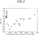
- FIGS. 1 and 2 each illustrate the relationship between carbon content conversion value C* or C** and DBTT, and the relationship between carbon content conversion value C* or C** and blanking cracking length ratio in examples and comparative examples where the carbon content conversion value C* or C** is outside an appropriate range.
- DBTT is -40 °C or lower and blanking cracking length ratio is 10 % or less when content conversion value C* or C** is in a range of 0.010 mass% to 0.100 mass%.
- FIG. 3 illustrates the relationship between Fe content in Fe precipitates and blanking cracking length ratio in examples and comparative examples where the Fe content in Fe precipitates is outside an appropriate range.
- blanking cracking length ratio can be 10 % or less.
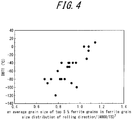
- FIG. 4 illustrates the relationship between (an average grain size of top 5 % ferrite grains in ferrite grain size distribution of rolling direction)/(4000/TS) 2 and DBTT in examples and comparative examples where the average grain size of top 5 % ferrite grains in ferrite grain size distribution of rolling direction cross section is outside an appropriate range.
- DBTT is -40 °C or lower when (an average grain size of top 5 % ferrite grains in ferrite grain size distribution of rolling direction cross section)/(4000/TS) 2 is 1.0 or less, in other words, DBTT is -40 °C or lower when an average grain size of top 5 % ferrite grains in ferrite grain size distribution of rolling direction cross section is (4000/TS) 2 ⁇ m or less in relation to tensile strength TS in unit of MPa.
Landscapes
- Chemical & Material Sciences (AREA)
- Engineering & Computer Science (AREA)
- Mechanical Engineering (AREA)
- Materials Engineering (AREA)
- Metallurgy (AREA)
- Organic Chemistry (AREA)
- Crystallography & Structural Chemistry (AREA)
- Physics & Mathematics (AREA)
- Thermal Sciences (AREA)
- Heat Treatment Of Sheet Steel (AREA)
- Metal Rolling (AREA)
- Heat Treatment Of Steel (AREA)
Abstract
Description
- This disclosure relates to a high-strength thin steel sheet having excellent blanking workability and toughness which are suitable for applications, for example, suspension parts such as lower arms and frames, frameworks such as pillars and members as well as their reinforcing members, door impact beams, and seat members of automobiles, and structural members for vending machines, desks, consumer electrical appliances, office automation equipment, building materials, and the like. This disclosure also relates to a method for manufacturing the high-strength thin steel sheet.
- In recent years, responding to increasing public concern about global environment issues, there has been a growing demand for, for example, curbing use of thick steel sheets which necessitate relatively large CO2 emission during manufacturing of the steel sheets. Furthermore, in the automobile industry, there has been a growing demand for, for example, lighter-weight vehicles which improve a fuel consumption rate while reducing exhaust gas. For these reasons, steel sheets have been made stronger and thinner.
- High-strength steel sheets generally have poor blanking workability and toughness. Therefore, it is desired to develop a high-strength thin which can be used for parts molded by press blanking or for parts requiring toughness or, particularly, for parts that are molded by press punching and require toughness at the same time.
- For example,
JP 2008-261029 A - Additionally,
WO 2013/022043 (PTL 2) describes a steel sheet excellent in toughness, which is a "high yield ratio hot rolled steel sheet which has an excellent low temperature impact energy absorption and HAZ softening resistance characterized by comprising, by mass%, C: 0.04 % to 0.09 %, Si: 0.4 % or less, Mn: 1.2 % to 2.0 %, P: 0.1 % or less, S: 0.02 % or less, Al: 1.0 % or less, Nb: 0.02 % to 0.09 %, Ti: 0.02 % to 0.07 %, and N: 0.005 % or less, a balance of Fe and unavoidable impurities, where 2.0 ≤ Mn + 8[%Ti] + 12[%Nb] ≤ 2.6, and having a metal structure which comprises an area percentage of pearlite of 5 % or less, a total area percentage of martensite and retained austenite of 0.5 % or less, and a balance of one or both of ferrite and bainite, having an average grain size of ferrite and bainite of 10 µm or less, having an average grain size of alloy carbonitrides with incoherent interfaces which contain Ti and Nb of 20 nm or less, having a yield ratio of 0.85 or more, and having a maximum tensile strength of 600 MPa or more". -
- PTL 1:
JP 2008-261029 A - PTL 2:
WO 2013/022043 - However, for the steel sheet described in PTL 1, conditions required for excellent toughness such as the grain size of precipitates were not taken into consideration, and there was a problem that excellent blanking workability and toughness could not be compatibly attained.
- Additionally, for the steel sheet described in
PTL 2, conditions required for excellent blanking workability were not taken into consideration, and there was also a problem that excellent blanking workability and toughness could not be compatibly attained. - To solve the above problems, it could be helpful to provide a high-strength thin steel sheet having both of excellent blanking workability and excellent toughness, as well as an advantageous manufacturing method thereof.
- The high-strength thin steel sheet in this disclosure is intended for a steel sheet having a thickness of 1 mm to 4 mm. In addition to a hot rolled steel sheet, the high-strength thin steel sheet in this disclosure also includes a steel sheet which has been subjected to surface treatment such as hot-dip galvanizing, galvannealing and electrogalvanization. Steel sheets obtained by subjecting the above-mentioned steel sheets to, for example, chemical conversion treatment to form a layer thereon are also included. Note that the sheet thickness does not include the thickness of planting or layer.
- As a result of a keen study to solve the above problems, we discovered the following.
- (1) Blanking workability can be significantly improved by having a certain composition and simultaneously precipitating fine precipitates of Ti, Nb, V and the like whose grain sizes are less than 20 nm and Fe precipitates such as cementite in an appropriate amount.
Regarding this mechanism, our consideration is as follows. Fe precipitates are precipitated, and these Fe precipitates serve as origins of cracks during blanking. Additionally, fine precipitates of Ti, Nb, V and the like promote propagation of the cracks. Therefore, it is considered that by precipitating Fe precipitates and fine precipitates of Ti, Nb, V and the like in an appropriate amount, end face cracking during blanking is suppressed, and accordingly, blanking workability is significantly improved.
Examples of fine precipitates of Ti, Nb, V and the like include carbide, composite carbide, carbonitride and composite carbonitride of Ti, Nb and V. Depending on the composition, it is Ti, Nb, V, Mo, Ta and W in some cases. Examples of Fe precipitates include cementite i.e. θ carbide and ε carbide. - (2) The ferrite grain size in the rolling direction of a steel sheet has a great influence on toughness. Particularly, the average grain size of top 5 % large grain sizes greatly influences toughness. By appropriately controlling the average grain size of ferrite whose grain size is top 5 % large according to tensile strength TS (MPa), toughness can be significantly improved.
- Furthermore, since the above-mentioned fine precipitates of Ti, Nb, V and the like serve as origins of transition, toughness is further improved.
- This disclosure is based on the aforementioned discoveries and further studies.
- Specifically, the primary features of this disclosure are as described below.
- 1. A high-strength thin steel sheet comprising a chemical composition containing (consisting of), in mass%, C: 0.05 % to 0.20 %, Si: 0.6 % to 1.5 %, Mn: 1.3 % to 3.0 %, P: 0.10 % or less, S: 0.030 % or less, Al: 0.10 % or less, N: 0.010 % or less, and at least one selected from Ti: 0.01 % to 1.00 %, Nb: 0.01 % to 1.00 %, and V: 0.01 % to 1.00 %, the balance consisting of Fe and inevitable impurities, where
a conversion value C* of total carbon contents in Ti, Nb and V precipitates whose grain sizes are less than 20 nm, defined by the following formula (1), is 0.010 mass% to 0.100 mass%,
Fe content in Fe precipitates is 0.03 mass% to 0.50 mass%, and
an average grain size of ferrite grains whose grain sizes are top 5 % large in ferrite grain size distribution of rolling direction cross section is (4000/TS)2 µm or less, the TS indicating tensile strength in unit of MPa,
- 2. The high-strength thin steel sheet according to 1., where the composition further contains, in mass%, at least one selected from Mo: 0.005 % to 0.50 %, Ta: 0.005 % to 0.50 %, and W: 0.005 % to 0.50 %,
a conversion value C** of total carbon contents in Ti, Nb, V, Mo, Ta and W precipitates whose grain sizes are less than 20 nm, defined by the following formula (2), is 0.010 mass% to 0.100 mass%,
- 3. The high-strength thin steel sheet according to 1. or 2., where the composition further contains, in mass%, at least one selected from Cr: 0.01 % to 1.00 %, Ni: 0.01 % to 1.00 %, and Cu: 0.01 % to 1.00 %.
- 4. The high-strength thin steel sheet according to any one of 1. to 3., where the composition further contains, in mass%, Sb: 0.005 % to 0.050 %.
- 5. The high-strength thin steel sheet according to any one of 1. to 4., where the composition further contains, in mass%, one or both selected from Ca: 0.0005 % to 0.0100 % and REM: 0.0005 % to 0.0100 %.
- 6. A method for manufacturing the high-strength thin steel sheet according to any one of 1. to 5., including:
- hot rolling a steel slab having the composition according to any one of 1. to 5. to obtain a steel sheet, the hot rolling comprising rough rolling and finish rolling; and
- cooling and coiling the steel sheet after completing the finish rolling, where
- cumulative strain Rt defined by the following formula (3) in the finish rolling is 1.3 or more and finisher delivery temperature is 820 °C or higher and lower than 930 °C,
- the steel sheet is cooled down from the finisher delivery temperature to a temperature where slow cooling starts at an average cooling rate of 30 °C/s or higher after completing the finish rolling, then slow cooling is started at a temperature of 750 °C to 600 °C where an average cooling rate is lower than 10 °C/s and cooling time is 1 second to 10 seconds during the slow cooling, and the steel sheet is cooled down to a coiling temperature of 350 °C or higher and lower than 530 °C at an average cooling rate of 10 °C/s or higher after completing the slow cooling,


- provided that when exp{-(11800 + 2 × 10³ × [C])/(Tn + 273) + 13.1 - 0.1 × [C]} exceeds 100, a value thereof is set to be 100.
- 7. The method for manufacturing a high-strength thin steel sheet according to 6., where an additional work is performed with a sheet thickness reduction rate being 0.1 % to 3.0 % after the hot rolling.
- This disclosure provides a high-strength thin steel sheet having excellent blanking workability and toughness which are suitable for applications such as members for automobiles and various structural members, and therefore has an industrially significant advantageous effect.
- The disclosure will be further described below with reference to the accompanying drawings, where
-
FIG. 1 illustrates the relationship between carbon content conversion value C* or C** and blanking cracking length ratio in examples and comparative examples where the carbon content conversion value C* or C** is outside an appropriate range, -
FIG. 2 illustrates the relationship between carbon content conversion value C* or C** and DBTT in examples and comparative examples where the carbon content conversion value C* or C** is outside an appropriate range, -
FIG. 3 illustrates the relationship between Fe content in Fe precipitates and blanking cracking length ratio in examples and comparative examples where the Fe content in Fe precipitates is outside an appropriate range, and -
FIG. 4 illustrates the relationship between (an average grain size of top 5 % ferrite grains in ferrite grain size distribution of rolling direction cross section)/(4000/TS)2 and DBTT in examples and comparative examples where the average grain size of top 5 % ferrite grains in ferrite grain size distribution of rolling direction is outside an appropriate range. - The following describes this disclosure in detail.
- First, the chemical composition of the high-strength thin steel sheet of this disclosure will be described. Hereinafter, the unit "%" relating to the content of elements in the chemical composition refers to "mass%" unless specified otherwise.
- C forms fine carbide, composite carbide, carbonitride and composite carbonitride of Ti, Nb, V and the like, which will be simply referred to as precipitates hereinafter, and contributes to improvement in strength, blanking workability and toughness. Additionally, C forms cementite with Fe, which also contributes to improvement in blanking workability. Therefore, C content should be 0.05 % or more. On the other hand, C suppresses ferrite transformation, and accordingly an excessive amount of C suppresses formation of fine precipitates of Ti, Nb, V and the like. Additionally, an excessive amount of C forms too much cementite, leading to deterioration of toughness. Therefore, C content should be 0.20 % or less. C content is preferably 0.15 % or less. C content is more preferably 0.12 % or less.
- Si accelerates ferrite transformation and promotes formation of fine precipitates of Ti, Nb, V and the like which precipitate simultaneously with the transformation during slow cooling performed in the cooling after hot rolling when manufacturing the steel sheet. Si also contributes to improvement in strength as a solid-solution-strengthening element without greatly deteriorating formability. To obtain these effects, Si content should be 0.6 % or more. On the other hand, an excessive amount of Si accelerates the above-mentioned ferrite transformation too much. As a result, the precipitates of Ti, Nb, V and the like coarsen and eventually an appropriate amount of these fine precipitates cannot be obtained. Furthermore, not only toughness is deteriorated but also oxides of Si are likely to be formed on the surface of steel sheet, which accordingly tend to cause problems such as poor chemical conversion treatment on hot rolled steel sheets and non-coating on coated steel sheets. From this point of view, Si content should be 1.5 % or less. Si content is preferably 1.2 % or less.
- Mn suppresses ferrite transformation before the start of slow cooling and suppresses coarsening of precipitates of Ti, Nb, V and the like during the cooling after hot rolling when manufacturing the steel sheet. Mn also contributes to improvement in strength by solid solution strengthening. Furthermore, M is bonded to harmful S in the steel to form MnS, thereby rendering the S harmless. To obtain these effects, Mn content should be 1.3 % or more. Mn content is preferably 1.5 % or more. On the other hand, an excessive amount of Mn leads to slab cracking, suppresses ferrite transformation, and suppresses formation of fine precipitates of Ti, Nb, V and the like. Therefore, Mn content should be 3.0 % or less. Mn content is preferably 2.5 % or less. Mn content is more preferably 2.0 % or less.
- P segregates at grain boundaries, deteriorating ductility and toughness. Additionally, a large amount of P accelerates ferrite transformation before the start of slow cooling and coarsens precipitates of Ti, Nb, V and the like during the cooling after hot rolling when manufacturing the steel sheet. Therefore, P content should be 0.10 % or less. P content is preferably 0.05 % or less. P content is more preferably 0.03 % or less. P content is still more preferably 0.01 % or less. The lower limit of P content is not particularly limited. However, since excessive removal of P leads to an increase in cost, the lower limit of P content is preferably 0.003 %.
- S decreases ductility during hot rolling, thereby inducing hot cracking and deteriorating surface characteristics. Additionally, S contributes little to strength, and, as an impurity element, leads to formation of coarse sulfide, thereby deteriorating ductility and stretch flangeability. For these reason, it is desirable to reduce S as much as possible. Therefore, S content should be 0.030 % or less. S content is preferably 0.010 % or less. S content is more preferably 0.003 % or less. S content is still more preferably 0.001 % or less. The lower limit of S content is not particularly limited. However, since excessive removal of S leads to an increase in cost, the lower limit of S content is preferably 0.0003 %.
- When Al content exceeds 0.10 %, toughness and weldability are greatly deteriorated. Additionally, Al oxide is likely to be formed on the surface, which may accordingly cause problems such as poor chemical conversion treatment on hot rolled steel sheets and non-coating on coated steel sheets. Therefore, Al content should be 0.10 % or less. Al content is preferably 0.06 % or less. Although the lower limit of Al content is not particularly limited, there is no problem if Al is contained in an amount of 0.01 % or more as Al-killed steel.
- Although N forms coarse nitrides at a high temperature with Ti, Nb, V and the like, these nitrides contribute little to strength. Therefore, a large amount of N lowers the effect of increasing strength of Ti, Nb, and V and deteriorates toughness. Additionally, since N causes slab cracking during hot rolling, surface flaws may occur. Thus, N content should be 0.010 % or less. N content is preferably 0.005 % or less. N content is more preferably 0.003 % or less. N content is still more preferably 0.002 % or less. The lower limit of N content is not particularly limited. However, since excessive removal of N leads to an increase in cost, the lower limit of N content is preferably 0.0010 %.
- At least one selected from Ti: 0.01 % to 1.00 %, Nb: 0.01 % to 1.00 % and V: 0.01 % to 1.00 %
- Ti, Nb and V form fine precipitates with C, increasing strength and contributing to improvement in blanking workability and toughness. To obtain such effect, it is necessary to contain at least one selected from Ti, Nb and V, each at an amount of 0.01 % or more. The amount is preferably 0.05 % or more. On the other hand, even Ti, Nb and V are contained each at an amount of more than 1.00 %, the effect of increasing strength will not be improved more. On the contrary, their fine precipitates excessively precipitate, deteriorating toughness and blanking workability. Therefore, contents of Ti, V and Nb should be each 1.00 % or less. Contents of Ti, V and Nb are preferably each 0.80 % or less.
- In addition to the basic components described above, the high-strength thin steel sheet of this disclosure may also contain appropriate amounts of following elements in order to further improve the strength, blanking workability and toughness.
- At least one selected from Mo: 0.005 % to 0.50 %, Ta: 0.005 % to 0.50 %, and W: 0.005 % to 0.50 %
- Similar to Ti, Nb and V, Mo, Ta and W form fine precipitates with C, increasing strength and contributing to improvement in blanking workability and toughness. Therefore, when containing Mo, Ta and W, contents of Mo, Ta and W are preferably each 0.005 % or more. Contents of Mo, Ta and W are more preferably each 0.01 % or more. On the other hand, even Mo, Ta and W are contained each at an amount of more than 0.50 %, the effect of increasing strength will not be improved more. On the contrary, their fine precipitates excessively precipitate, deteriorating toughness and blanking workability. Thus, when containing Mo, Ta and W, contents of Mo, Ta and W are preferably each 0.50 % or less. Contents of Mo, Ta and W are more preferably each 0.40 % or less.
- Cr, Ni and Cu improve strength and toughness by refining the structure. Therefore, when containing Cr, Ni and Cu, contents of Cr, Ni and Cu are preferably each 0.01 % or more. On the other hand, containing Cr, Ni and Cu each at an amount of more than 1.00 % saturates the effect and increases cost. Thus, when containing Cr, Ni and Cu, contents of Cr, Ni and Cu are preferably each 1.00 % or less.
- Sb segregates on the surface during hot rolling, thereby preventing the slab from being nitrided and suppressing formation of coarse nitrides. Therefore, when containing Sb, Sb content is preferably 0.005 % or more. On the other hand, containing Sb at an amount of more than 0.050 % saturates the effect and increases cost. Thus, when containing Sb, Sb content is preferably 0.050 % or less.
- Ca and REM improve ductility and stretch flangeability by controlling formation of sulfide. Therefore, when containing Ca and REM, contents of Ca and REM are preferably each 0.0005 % or more. On the other hand, containing Ca and REM at an amount of more than 0.0100 % saturates the effect and increases cost. Thus, when containing Ca and REM, Ca content and REM content are preferably each 0.0100 % or less.
- The balance other than the above components is Fe and inevitable impurities.
- Next, the reason why the structure of the high-strength thin steel sheet of this disclosure is limited will be described.
conversion value C* of total carbon contents in Ti, Nb and V precipitates whose grain sizes are less than 20 nm: 0.010 mass% to 0.100 mass%, or, conversion value C** of total carbon contents in Ti, Nb, V, Mo, Ta and W precipitates whose grain sizes are less than 20 nm: 0.010 mass% to 0.100 mass% - Ti, Nb and V precipitates whose grain sizes are less than 20 nm contribute to improvement in blanking workability and toughness. To obtain such effect, conversion value C* of total carbon contents in Ti, Nb and V precipitates whose grain sizes are less than 20 nm (hereinafter simply referred to as carbon content conversion value C*) should be 0.010 mass% or more. Carbon content conversion value C* is preferably 0.015 mass%.
- On the other hand, an excessive amount of such precipitates deteriorates blanking workability and toughness because of the internal stress around the precipitates. Therefore, carbon content conversion value C* should be 0.100 mass% or less. Carbon content conversion value C* is preferably 0.080 mass% or less. Carbon content conversion value C* is more preferably 0.050 mass% or less.
- Here, C* is calculated by the following formula (1).

- When the high-strength thin steel sheet of this disclosure contains Mo, Ta and W in addition to at least one selected from Ti, Nb and V, conversion value C** of total carbon contents in Ti, Nb, V, Mo, Ta and W precipitates whose grain sizes are less than 20 nm (hereinafter simply referred to as carbon content conversion value C**) defined by the following formula (2) is 0.010 mass% to 0.100 mass%. The preferred range of C** and its reason are similar to that of C*.


- Since Ti, Nb and V precipitates and the like whose grain sizes are 20 nm or more contribute little to improvement in blanking workability and toughness, this disclosure chooses Ti, Nb and V precipitates and the like whose grain sizes are less than 20 nm.
- Fe content in Fe precipitates: 0.03 mass% to 0.50 mass%
- Fe precipitates, particularly cementite, serve as origins of cracks during blanking and contribute to improvement in blanking workability. To obtain such effect, Fe content in Fe precipitates should be 0.03 mass% or more. Fe content in Fe precipitates is preferably 0.05 mass% or more. Fe content in Fe precipitates is more preferably 0.10 mass% or more. On the other hand, when Fe precipitates is excessive, the Fe precipitates may become origins of brittle fracture. Therefore, Fe content in Fe precipitates should be 0.50 mass% or less. Fe content in Fe precipitates is preferably 0.40 mass% or less. Fe content in Fe precipitates is more preferably 0.30 mass% or less.
- Average grain size of ferrite grains whose grain sizes are top 5 % large in ferrite grain size distribution of rolling direction cross section: (4000/TS)2 µm or less, the TS indicating tensile strength in unit of MPa
- A large average grain size of ferrite grains whose grain sizes are top 5 % large in ferrite grain size distribution of rolling direction cross section greatly deteriorates toughness. Particularly, since toughness tends to decrease as tensile strength TS (MPa) increases, it is important to reduce the grain size according to tensile strength. Therefore, the average grain size of grain sizes that are top 5 % large in ferrite grain size distribution of rolling direction cross section (hereinafter simply referred to as average grain size of top 5 %) should be (4000/TS (MPa))2 µm or less. The TS here is tensile strength of steel sheet in unit of MPa. The average grain size of top 5 % is preferably (3500/TS (MPa))2 µm or less. Note that TS is expressed in unit of MPa. When calculating the above (4000/TS)2 and (3500/TS)2, M is only used as Mantissa part rather than M (=106). For example, when TS is 780 MPa, values of (4000/TS)2 and (3500/TS)2 can be calculated with TS = 780. Although the lower limit of the average grain size is not particularly limited, the lower limit is usually 5.0 µm.
- The high-strength thin steel sheet of this disclosure preferably has a tensile strength TS of 780 MPa or more.
- The structure of the high-strength thin steel sheet of this disclosure is preferably a structure mainly composed of ferrite, specifically, a structure composed of ferrite whose area ratio is 50 % or more with respect to the entire structure and the balance. Structure other than ferrite may be bainite and martensite.
- The following describes a method for manufacturing the high-strength thin steel sheet of this disclosure.
- The method for manufacturing the high-strength thin steel sheet of this disclosure includes hot rolling a steel slab having the above-mentioned composition to obtain a steel sheet, the hot rolling comprising rough rolling and finish rolling, and cooling and coiling the steel sheet after completing the finish rolling.
- When using this method, cumulative strain Rt in the finish rolling is 1.3 or more, and finisher delivery temperature is 820 °C or higher and lower than 930 °C. The steel sheet is cooled down from the finisher delivery temperature to a temperature where slow cooling starts at an average cooling rate of 30 °C/s or higher after completing the finish rolling, then slow cooling is started at a temperature of 750 °C to 600 °C where an average cooling rate is lower than 10 °C/s and cooling time is 1 second to 10 seconds during the slow cooling. After completing the slow cooling, the steel sheet is cooled down to a coiling temperature of 350 °C or higher and lower than 530 °C at an average cooling rate of 10 °C/s or higher.
- The reasons for limiting the manufacturing conditions will be described below. Note that the smelting method for obtaining a steel slab is not particularly limited and a publicly-known smelting method such as a converter, an electric heating furnace or the like can be adopted. After smelting, it is preferable to form steel slabs by a continuous casting method from the perspective of, for example, productivity, but adopting publicly-known casting methods such as ingot casting-blooming or thin slab continuous casting to form steel slabs is also acceptable.
- By increasing cumulative strain Rt during finish rolling, ferrite grain size of the hot rolled steel sheet obtained after hot rolling, cooling, and coiling can be reduced. Particularly, by setting the cumulative strain during finish rolling to 1.3 or more, it is possible to introduce uniform strain into the hot rolled steel sheet by finish rolling. As a result, it is possible to reduce variations in the grain size of ferrite grains in the rolling direction and reduce the average grain size of the top 5 % ferrite grains. Therefore, cumulative strain Rt during finish rolling should be 1.3 or more. Cumulative strain Rt during finish rolling is preferably 1.5 or more. The upper limit of cumulative strain Rt during finish rolling is not particularly limited. However, a too large cumulative strain may excessively accelerate ferrite transformation during the cooling after hot rolling and lead to coarsening of precipitates of Ti, Nb, V and the like. Therefore, cumulative strain Rt during finish rolling is preferably 2.2 or less. Cumulative strain Rt during finish rolling is more preferably 2.0 or less.
- The cumulative strain Rt during finish rolling is defined by the following formula (3),


- However, when exp{-(11800 + 2 × 10³ × [C])/(Tn + 273) + 13.1 - 0.1 × [C]} exceeds 100, the value is set to be 100.
- When finisher delivery temperature is lower than 820 °C, ferrite transformation is accelerated before the start of slow cooling and precipitates of Ti, Nb, V and the like coarsen during the cooling after hot rolling. In a case where the finisher delivery temperature is in ferrite region, the precipitates of Ti, Nb, V and the like become coarser because of strain-induced precipitation. Additionally, ferrite crystal grains become elongated with a low temperature and cracks develop along the elongated grains, leading to significant deterioration of blanking workability. Therefore, finisher delivery temperature should be 820 °C or higher. Finisher delivery temperature is preferably 850 °C or higher. On the other hand, when finisher delivery temperature is 930 °C or higher, ferrite transformation is suppressed during the cooling after hot rolling, and formation of fine precipitates of Ti, Nb, V and the like is suppressed. Therefore, finisher delivery temperature should be lower than 930 °C. Finisher delivery temperature is preferably lower than 900 °C.
- The finisher delivery temperature here is the exit side temperature (°C) at an mth stand from upstream side when finish rolling is performed with m stands.
- When the average cooling rate from finisher delivery temperature to starting temperature of slow cooling is lower than 30 °C/s, ferrite transformation is accelerated and precipitates of Ti, Nb, V and the like coarsen. Therefore, the average cooling rate from finisher delivery temperature to starting temperature of slow cooling should be 30 °C/s or higher. The average cooling rate is preferably 50 °C/s or higher. The average cooling rate is more preferably 80 °C/s or higher. Although the upper limit of the average cooling rate is not particularly limited, it is about 200 °C/s from the perspective of temperature control.
- When starting temperature of slow cooling exceeds 750 °C, ferrite transformation takes place at a high temperature and ferrite crystal grains coarsen. Precipitates of Ti, Nb, V and the like also coarsen. Therefore, starting temperature of slow cooling should be 750 °C or lower. On the other hand, when starting temperature of slow cooling is lower than 600 °C, precipitates of Ti, Nb, V and the like are not sufficient. Therefore, starting temperature of slow cooling should be 600 °C or higher.
- When the average cooling rate during slow cooling is 10 °C/s or higher, ferrite transformation is not sufficient and the amount of fine precipitates of Ti, Nb, V and the like decreases. Therefore, the average cooling rate during slow cooling should be lower than 10 °C/s. The average cooling rate during slow cooling is preferably lower than 6 °C/s. Although the lower limit of average cooling rate during slow cooling is not particularly limited, it can be about 2 °C/s. The average cooling rate during slow cooling is preferably 4 °C/s or higher.
- When cooling time of slow cooling is less than 1 second, ferrite transformation is not sufficient and the amount of fine precipitates of Ti, Nb, V and the like decreases. Therefore, cooling time of slow cooling should be 1 second or more. Cooling time of slow cooling is preferably 2 seconds or more. Cooling time of slow cooling is more preferably 3 seconds or more. On the other hand, when cooling time of slow cooling exceeds 10 seconds, precipitates of Ti, Nb, V and the like coarsen. Ferrite crystal grains also coarsen. Therefore, cooling time of slow cooling should be 10 seconds or less. Cooling time of slow cooling is preferably 6 seconds or less.
- When the average cooling rate down to coiling temperature after slow cooling is lower than 10 °C/s, precipitates of Ti, Nb, V and the like coarsen. Ferrite crystal grains also coarsen. Therefore, the average cooling rate down to coiling temperature after slow cooling should be 10 °C/s or higher. The average cooling rate is preferably 30 °C/s or higher. The average cooling rate is more preferably 50 °C/s or higher. Although the upper limit of the average cooling rate is not particularly limited, it is about 100 °C/s from the perspective of temperature control.
- When coiling temperature is 530 °C or higher, precipitates of Ti, Nb, V and the like coarsen. Ferrite crystal grains also coarsen. Therefore, coiling temperature should be lower than 530 °C. Coiling temperature is preferably lower than 480 °C. On the other hand, when coiling temperature is lower than 350 °C, the generation of cementite, which is a precipitate of Fe and C, is suppressed. Therefore, coilng temperature should be 350 °C or higher.
- Note that the above finisher delivery temperature, starting temperature of slow cooling and coiling temperature are all temperatures at the surface of steel sheet and that the average cooling rate is also specified based on the temperature at the surface of steel sheet.
- After the hot rolling as described above, it is possible to perform an additional work with a sheet thickness reduction rate being 0.1 % or higher to increase the number of mobile dislocations and to further improve blanking workability. The sheet thickness reduction rate is preferably 0.3 % or higher. When the sheet thickness reduction rate exceeds 3.0 %, however, dislocations are difficult to move because of the interaction between the dislocations, and blanking workability deteriorates. Therefore, the sheet thickness reduction rate is preferably 3.0 % or lower when an additional work is performed after the hot rolling. The sheet thickness reduction rate is more preferably 2.0 % or lower. The sheet thickness reduction rate is still more preferably 1.0 % or lower.
- The above-mentioned work may be a process of rolling by rolls or applying tensile to a steel sheet, or a combination of both.
- Furthermore, composite plating of zinc plating and Al or composite plating of zinc and Al, composite plating of zinc and Ni, Al plating, composite plating of Al and Si, and the like may be applied to the steel sheet obtained as described above. A layer formed by chemical conversion treatment or the like is also acceptable.
- Molten steel having the composition listed in Table 1 was obtained by a publicly-known smelting method and continuously cast to obtain steel slabs. These slabs were heated and subjected to rough rolling, and then finish rolling was performed under the conditions listed in Table 2. After the finish rolling, cooling and coiling were performed to obtain hot rolled steel sheets. The finish rolling was carried out by a hot rolling mill consisting of 7 stands. Additionally, some of the steel sheets were further subjected to reduction rolling at room temperature by a rolling roll.
-
Table 1 No. Chemical composition (mass%) Remarks C Si Mn P S Al N Ti Nb V Mo Ta W Others 1 0.10 1.5 1.6 0.07 0.008 0.09 0.005 0.15 0.06 0.17 - - - Sb:0.008 Conforming steel 2 0.14 0.7 1.7 0.01 0.001 0.06 0.003 0.10 - 0.21 0.42 - - Sb:0.012 Conforming steel 3 0.07 1.0 2.5 0.02 0.023 0.05 0.003 0.11 0.03 0.05 0.03 0.02 0.03 - Conforming steel 4 0.17 1.0 2.1 0.02 0.002 0.04 0.006 0.06 - 0.55 - - - - Conforming steel 5 0.06 0.7 1.5 0.01 0.001 0.05 0.003 0.25 - - - - - - Conforming steel 6 0.15 0.5 1.9 0.01 0.001 0.04 0.007 0.05 - 0.55 - - - - Comparative steel 7 0.06 1.0 1.7 0.01 0.003 0.03 0.004 0.21 0.05 - - - - - Conforming steel 8 0.15 1.6 1.5 0.03 0.021 0.04 0.005 0.06 - 0.52 - - - - Comparative steel 9 0.11 0.8 1.7 0.02 0.001 0.03 0.004 0.05 - 0.25 - - - - Conforming steel 10 0.19 1.2 1.6 0.01 0.002 0.04 0.005 - - 0.77 - - - - Conforming steel 11 0.12 1.0 1.4 0.11 0.001 0.04 0.008 0.09 - 0.35 - - - - Comparative steel 12 0.15 0.7 1.9 0.09 0.007 0.05 0.004 0.09 - 0.54 - - 0.05 Ca:0.0040 Conforming steel 13 0.08 1.2 2.8 0.04 0.018 0.06 0.005 0.15 - 0.15 - - - Cr:0.03 Conforming steel 14 0.08 1.2 1.2 0.01 0.004 0.08 0.006 0.07 - 0.15 - - - - Comparative steel 15 0.05 1.3 1.4 0.02 0.001 0.06 0.005 0.19 - - - - - - Conforming steel 16 0.09 1.2 1.2 0.02 0.011 0.02 0.005 0.12 - 0.21 - - - - Comparative steel 17 0.12 1.1 1.4 0.01 0.002 0.03 0.005 0.05 - 0.22 0.35 - - - Conforming steel 18 0.11 1.1 1.6 0.01 0.002 0.03 0.005 0.11 - 0.25 - - - - Conforming steel 19 0.18 1.1 1.7 0.01 0.001 0.05 0.004 0.05 - 0.65 - - - - Conforming steel 20 0.11 1.0 1.5 0.01 0.001 0.04 0.004 0.14 - 0.27 - - - - Conforming steel 21 0.06 0.8 2.0 0.05 0.003 0.06 0.005 0.15 - - 0.05 - - - Conforming steel 22 0.12 1.1 1.5 0.01 0.003 0.04 0.004 0.19 - 0.28 - - - Ca:0.0060,REM:0.0070 Conforming steel 23 0.16 0.8 2.1 0.03 0.015 0.06 0.005 0.07 - 0.41 0.34 0.03 0.06 Cr:0.06,Ni:0.08,Cu:0.07,Sb:0.010, Ca:0.0030,REM:0.0050 Conforming steel 24 0.12 1.2 3.1 0.01 0.003 0.05 0.004 0.08 0.05 - 0.32 - - - Comparative steel 25 0.11 1.5 1.5 0.01 0.001 0.05 0.004 0.11 - 0.25 - - - Ca:0.0080 Conforming steel 26 0.12 1.7 1.4 0.01 0.001 0.07 0.004 0.07 0.05 0.35 - - - - Comparative steel 27 0.09 0.9 2.0 0.01 0.001 0.04 0.003 0.11 - 0.22 - - - - Conforming steel 28 0.13 1.6 1.5 0.03 0.003 0.03 0.005 - - 0.51 - - - - Comparative steel 29 0.07 0.8 1.8 0.01 0.001 0.04 0.003 0.15 - 0.15 - - - - Conforming steel 30 0.08 0.8 1.8 0.01 0.002 0.05 0.006 0.09 - 0.21 - - - Cr:0.05 Conforming steel 31 0.20 1.0 1.4 0.01 0.001 0.06 0.005 - - 0.95 - - - - Conforming steel 32 0.05 0.6 1.7 0.02 0.028 0.03 0.004 0.05 0.02 0.05 - - - - Conforming steel 33 0.22 0.9 1.6 0.02 0.002 0.06 0.006 0.06 0.05 0.89 0.22 - - - Comparative steel 34 0.09 1.4 2.2 0.05 0.013 0.07 0.008 0.12 - 0.25 - - - Cr:0.05,Ni:0.06,Cu.-O.05 Conforming steel 35 0.04 1.1 1.5 0.01 0.001 0.05 0.004 0.16 - - - - - Cr:0.04 Comparative steel 36 0.13 0.9 1.6 0.01 0.002 0.03 0.005 0.09 - 0.21 0.31 - - Cr:0.05 Conforming steel 37 0.11 1.3 1.3 0.08 0.005 0.05 0.003 0.14 - 0.31 - - - Ca:0.0080 Conforming steel 38 0.19 1.2 1.8 0.01 0.001 0.05 0.003 - - 1.10 - - - - Comparative steel Underline indicates that it is outside an appropriate range. 


- Test pieces were taken from the resulting steel sheets and subjected to the following evaluations (i) to (vi),
- (i) measurement of conversion value C* of total carbon contents in Ti, Nb and V precipitates whose grain sizes are less than 20 nm or conversion value C** of total carbon contents in Ti, Nb, V, Mo, Ta and W precipitates whose grain sizes are less than 20 nm,
- (ii) measurement of Fe content in Fe precipitates,
- (iii) measurement of average grain size of ferrite grains whose grain sizes are top 5 % large in ferrite grain size distribution of rolling direction cross section,
- (iv) tensile test,
- (v) blanking test, and
- (vi) evaluation of toughness.
- The evaluation results are listed in Table 3. Evaluation methods are as stated below.
- As described in
JP 4737278 B - Constant current electrolysis was carried out in a 10 % AA electrolytic solution using a test piece taken from the steel sheet as the anode, and a certain amount of the test piece was dissolved. Subsequently, extraction residue obtained by the electrolysis was filtered with a filter whose pore size is 0.2 µm to recover Fe precipitates. After dissolving the obtained Fe precipitates with mixed acid, Fe was quantified by ICP emission spectroscopy analysis, and Fe content in the Fe precipitates was calculated with the measurement result.
- Since the Fe precipitates are in an agglomerated state, Fe precipitates whose grain sizes are less than 0.2 µm also can be recovered by filtering the Fe precipitates with a filter having a pore size of 0.2 µm.
- A cross section of rolling direction - sheet thickness direction was embedded in resin and polished. After subjecting the cross section to nital etching, EBSD (Electron Backscatter Diffraction) measurement was made at three locations with a step size of 0.1 µm in an area of 100 µm × 100 µm where the center is the 1/4 sheet thickness position, a position corresponding to 1/4 of the sheet thickness in the depth direction from the surface of the steel sheet, and ferrite grain size distribution in the rolling direction was obtained with a setting where an orientation difference of 15° or more is the grain boundary.
- All of the steel sheets obtained as described above had a structure mainly composed of ferrite, which means the area ratio of ferrite is 50 % or more. The area ratio of ferrite can be obtained by embedding the cross section of rolling direction - sheet thickness direction in resin, polishing the cross section, subjecting the cross section to nital etching, observing three visual fields at 3000 times magnification under an SEM (Scanning Electron Microscope) on the 1/4 sheet thickness position, calculating the area ratio of constituent phase in the obtained structure micrograph for three visual fields, and averaging the values. Ferrite appears as a gray structure i.e. base steel structure in the above-mentioned structure micrograph.
- Additionally, ferrite grain size distribution in the rolling direction cross section was obtained by the so-called section method, in which nine lines are drawn at equal intervals parallel to the rolling direction for each measurement location in the EBSD measurement and the section length of each ferrite grain in the rolling direction is measured. The average value of the measured section lengths was taken as the average grain size of ferrite grains in the rolling direction. The average value of grain sizes of ferrite grains up to 5 % in an order from the largest grain size was taken as the average grain size of top 5 % large grain sizes. When selecting the ferrite grains whose grain sizes are top 5 % large, ferrite grains having a grain size of less than 0.1 µm were excluded. Additionally, in order to obtain the ferrite grain size distribution, 200 or more ferrite grains were measured to obtain their grain sizes.
- In tensile test, a JIS No. 5 tensile test piece was cut out with the longitudinal direction being the direction orthogonal to the rolling direction. The tensile test was carried out according to JIS Z 2241, and yield strength YP, tensile strength TS, and total elongation E1 were evaluated.
- Blanking workability was evaluated by blanking a hole having a diameter of 10 mm three times at a time with a clearance of 20 %, observing the blanked end face all around and calculating the average value of perimeter ratio of the portion where cracking had occurred (hereinafter also referred to as blanking cracking length ratio). When the blanking cracking length ratio is 10 % or less, blanking workability can be considered as excellent.
- The evaluation conditions were set according to JIS Z 2242 except the sheet thickness, which was the original thickness as listed in Table 3, and a DBTT (Ductile-brittle Transition Temperature) was obtained by Charpy impact test. The V-notch test piece here was made so that the longitudinal direction was in the direction orthogonal to the rolling direction. When the DBTT (Ductile-brittle Transition Temperature) is lower than -40 °C, toughness can be considered as excellent.
-
Table 3 No. Sheet thickness (mm) Steel structure Tensile test Blanking test Evaluation of toughness Remarks C* or C** (mass%) Fe content in Fe precipitates (mass% ) Average grain size of ferrite in rolling direction (µm) Average grain size of ferrite whose grain size is top 5% large in rolling direction (µm) YP (MPa) TS (MPa) EI (%) (4000/TS)2 Blanking cracking length ratio (%) DBTT (°C) 1 2.9 0.055 0.13 6.9 14.6 760 860 18 21.6 0 -80 Exanple 2 2.4 0.038 0.22 5.2 12.8 880 1010 17 15.7 0 -80 Example 3 2.0 0.025 0.08 10.8 23.1 720 820 19 23.8 0 -100 Example 4 2.3 0.058 0.31 5.2 10.1 1020 1190 16 11.3 0 -40 Example 5 2.9 0.018 0.05 8.6 17.6 770 840 18 22.7 0 -120 Example 6 3.2 0.008 0.25 4.6 8.6 1060 1210 14 10.9 15 -20 Comparative Example 7 2.6 0.005 0.06 11.0 23.5 730 810 18 24.4 15 -30 Comparative Example 8 2.9 0.008 0.21 5.3 10.1 1050 1180 15 11.5 15 -30 Comparative Example 9 2.3 0.009 0.11 7.2 20.5 800 900 17 19.8 20 0 Comparative Example 10 2.6 0.090 0.35 4.5 8.1 1100 1280 14 9.8 5 -40 Example 11 2.6 0.009 0.18 6.9 12.5 920 1040 16 14.8 15 -30 Comparative Exanple 12 2.6 0.071 0.26 5.3 10.7 950 1200 15 11.1 5 -40 Example 13 4.0 0.035 0.07 8.8 18.3 730 850 18 22.1 0 -80 Example 14 2.6 0.008 0.09 7.6 19.8 720 820 18 23.8 20 -20 Comparative Example 15 2.3 0.008 0.03 11.8 27.8 750 810 18 24.4 20 10 Comparative Example 16 2.6 0.007 0.13 7.9 18.3 780 890 17 20.2 15 -20 Comparative Exanple 17 2.4 0.009 0.12 7.2 17.6 802 990 17 16.3 20 -10 Comparative Example 18 2.5 0.009 0.16 82 14.3 820 990 16 16.3 35 -20 Comparative Exanple 19 2.1 0.071 0.33 4.8 9.5 1060 1220 15 10.7 5 -50 Example 20 2.6 0.051 0.15 6.8 13.2 850 1020 17 15.4 0 -80 Example 21 2.6 0.015 0.04 11.2 22.5 720 810 19 24.4 5 -90 Example 22 2.3 0.046 0.16 5.2 10.9 920 1080 17 13.7 0 -60 Example 23 2.8 0.062 0.28 5.3 9.5 1050 1230 15 106 5 -40 Example 24 2.5 0.007 0.19 8.1 16.8 760 910 17 19.3 20 -20 Comparative Example 25 2.9 0.008 0.17 9.8 14.6 830 950 17 17.7 20 -20 Comparative Example 26 2.5 0.009 0.16 7.1 16.3 880 1030 16 15.1 20 0 Comparative Example 27 2.8 0.025 0.02 76 17.9 790 890 16 20.2 15 -40 Comparative Example 28 2.9 0.006 0.20 4.8 8.9 1020 1170 14 11.7 25 -30 Comparative Example 29 2.2 0.021 0.07 10.9 20.1 800 920 17 18.9 5 -30 Comparative Example 30 3.2 0.005 0.09 7.2 15.6 780 900 17 19.8 25 -20 Comparative Example 31 2.9 0.095 0.45 3.9 8.2 1160 1350 13 8.8 10 -40 Example 32 3.2 0.010 0.03 9.6 19.3 710 780 20 26.3 10 -80 Example 33 3.2 0.009 0.55 4.3 8.5 1080 1320 13 9.2 20 10 Comparative Example 34 3.6 0.057 0.10 7.5 15,9 710 840 19 22.7 0 -90 Example 35 2.9 0.008 0.02 9.8 22.3 710 790 18 25.6 30 20 Comparative Example 36 2.3 0.042 0.18 5.6 11.9 1000 1100 16 13.2 0 -50 Example 37 2.6 0.042 0.15 5.3 12.8 880 1060 17 14.2 0 -50 Example 38 2.5 0.110 0.35 3.9 7.9 1250 1320 14 9.2 20 -10 Comparative Example Underline indicates that it is outside an appropriate range. - According to Table 3, it is understood that a high-strength thin steel sheet having excellent blanking workability and toughness as well as a high strength where the tensile strength TS is 780 MPa or more can be obtained in all examples.
- Additionally,
FIGS. 1 and2 each illustrate the relationship between carbon content conversion value C* or C** and DBTT, and the relationship between carbon content conversion value C* or C** and blanking cracking length ratio in examples and comparative examples where the carbon content conversion value C* or C** is outside an appropriate range. - According to
FIGS. 1 and2 , it is understood that DBTT is -40 °C or lower and blanking cracking length ratio is 10 % or less when content conversion value C* or C** is in a range of 0.010 mass% to 0.100 mass%. - Furthermore,
FIG. 3 illustrates the relationship between Fe content in Fe precipitates and blanking cracking length ratio in examples and comparative examples where the Fe content in Fe precipitates is outside an appropriate range. - According to
FIG. 3 , it is understood that by controlling Fe content in Fe precipitates to a range of 0.03 mass% to 0.50 mass%, blanking cracking length ratio can be 10 % or less. - Moreover,
FIG. 4 illustrates the relationship between (an average grain size of top 5 % ferrite grains in ferrite grain size distribution of rolling direction)/(4000/TS)2 and DBTT in examples and comparative examples where the average grain size of top 5 % ferrite grains in ferrite grain size distribution of rolling direction cross section is outside an appropriate range. - According to
FIG.4 , it is understood that DBTT is -40 °C or lower when (an average grain size of top 5 % ferrite grains in ferrite grain size distribution of rolling direction cross section)/(4000/TS)2 is 1.0 or less, in other words, DBTT is -40 °C or lower when an average grain size of top 5 % ferrite grains in ferrite grain size distribution of rolling direction cross section is (4000/TS)2 µm or less in relation to tensile strength TS in unit of MPa.
Claims (7)
- A high-strength thin steel sheet comprising a chemical composition containing, in mass%, C: 0.05 % to 0.20 %, Si: 0.6 % to 1.5 %, Mn: 1.3 % to 3.0 %, P: 0.10 % or less, S: 0.030 % or less, Al: 0.10 % or less, N: 0.010 % or less, and at least one selected from Ti: 0.01 % to 1.00 %, Nb: 0.01 % to 1.00 %, and V: 0.01 % to 1.00 %, the balance consisting of Fe and inevitable impurities, wherein
a conversion value C* of total carbon contents in Ti, Nb and V precipitates whose grain sizes are less than 20 nm, defined by the following formula (1), is 0.010 mass% to 0.100 mass%,
Fe content in Fe precipitates is 0.03 mass% to 0.50 mass%, and
an average grain size of ferrite grains whose grain sizes are top 5 % large in ferrite grain size distribution of rolling direction cross section is (4000/TS)2 µm or less, the TS indicating tensile strength in unit of MPa,
- The high-strength thin steel sheet according to claim 1, wherein the composition further comprises, in mass%, at least one selected from Mo: 0.005 % to 0.50 %, Ta: 0.005 % to 0.50 %, and W: 0.005 % to 0.50 %,
a conversion value C** of total carbon contents in Ti, Nb, V, Mo, Ta and W precipitates whose grain sizes are less than 20 nm, defined by the following formula (2), is 0.010 mass% to 0.100 mass%,
- The high-strength thin steel sheet according to claim 1 or 2, wherein the composition further comprises, in mass%, at least one selected from Cr: 0.01 % to 1.00 %, Ni: 0.01 % to 1.00 %, and Cu: 0.01 % to 1.00 %.
- The high-strength thin steel sheet according to any one of claims 1 to 3, wherein the composition further comprises, in mass%, Sb: 0.005 % to 0.050 %.
- The high-strength thin steel sheet according to any one of claims 1 to 4, wherein the composition further comprises, in mass%, one or both selected from Ca: 0.0005 % to 0.0100 % and REM: 0.0005 % to 0.0100 %.
- A method for manufacturing the high-strength thin steel sheet according to any one of claims 1 to 5, comprising:hot rolling a steel slab having the composition according to any one of claims 1 to 5 to obtain a steel sheet, the hot rolling comprising rough rolling and finish rolling; andcooling and coiling the steel sheet after completing the finish rolling, whereincumulative strain Rt defined by the following formula (3) in the finish rolling is 1.3 or more and finisher delivery temperature is 820 °C or higher and lower than 930 °C,the steel sheet is cooled down from the finisher delivery temperature to a temperature where slow cooling starts at an average cooling rate of 30 °C/s or higher after completing the finish rolling, then slow cooling is started at a temperature of 750 °C to 600 °C where an average cooling rate is lower than 10 °C/s and cooling time is 1 second to 10 seconds during the slow cooling, and the steel sheet is cooled down to a coiling temperature of 350 °C or higher and lower than 530 °C at an average cooling rate of 10 °C/s or higher after completing the slow cooling,

 provided that when exp{-(11800 + 2 × 10³ × [C])/(Tn + 273) + 13.1 - 0.1 × [C]} exceeds 100, a value thereof is set to be 100.
 - The method for manufacturing a high-strength thin steel sheet according to claim 6, wherein an additional work is performed with a sheet thickness reduction rate being 0.1 % to 3.0 % after the hot rolling.
Applications Claiming Priority (2)
| Application Number | Priority Date | Filing Date | Title |
|---|---|---|---|
| JP2015135432 | 2015-07-06 | ||
| PCT/JP2016/003207 WO2017006563A1 (en) | 2015-07-06 | 2016-07-05 | High-strength thin steel sheet and method for manufacturing same |
Publications (3)
| Publication Number | Publication Date |
|---|---|
| EP3321387A4 EP3321387A4 (en) | 2018-05-16 |
| EP3321387A1 true EP3321387A1 (en) | 2018-05-16 |
| EP3321387B1 EP3321387B1 (en) | 2020-04-15 |
Family
ID=57686171
Family Applications (1)
| Application Number | Title | Priority Date | Filing Date |
|---|---|---|---|
| EP16821038.3A Active EP3321387B1 (en) | 2015-07-06 | 2016-07-05 | High-strength thin steel sheet and method for manufacturing same |
Country Status (7)
| Country | Link |
|---|---|
| US (1) | US10526678B2 (en) |
| EP (1) | EP3321387B1 (en) |
| JP (1) | JP6103160B1 (en) |
| KR (1) | KR102064147B1 (en) |
| CN (1) | CN107849657A (en) |
| MX (1) | MX2017016553A (en) |
| WO (1) | WO2017006563A1 (en) |
Families Citing this family (4)
| Publication number | Priority date | Publication date | Assignee | Title |
|---|---|---|---|---|
| WO2016143298A1 (en) * | 2015-03-06 | 2016-09-15 | Jfeスチール株式会社 | High strength steel sheet and manufacturing method therefor |
| JP6179584B2 (en) * | 2015-12-22 | 2017-08-16 | Jfeスチール株式会社 | High strength steel plate with excellent bendability and method for producing the same |
| JP6424908B2 (en) * | 2017-02-06 | 2018-11-21 | Jfeスチール株式会社 | Hot-dip galvanized steel sheet and method of manufacturing the same |
| WO2020179387A1 (en) * | 2019-03-07 | 2020-09-10 | 日本製鉄株式会社 | Hot rolled steel sheet and production method thereof |
Family Cites Families (14)
| Publication number | Priority date | Publication date | Assignee | Title |
|---|---|---|---|---|
| WO2007132548A1 (en) | 2006-05-16 | 2007-11-22 | Jfe Steel Corporation | High-strength hot-rolled steel plate having excellent stretch properties, stretch flanging properties and tension fatigue properties, and method for production thereof |
| JP4879808B2 (en) * | 2007-04-13 | 2012-02-22 | 新日本製鐵株式会社 | High-strength hot-rolled steel sheet excellent in punching workability and manufacturing method thereof |
| JP5272412B2 (en) | 2008-01-17 | 2013-08-28 | Jfeスチール株式会社 | High strength steel plate and manufacturing method thereof |
| JP5187003B2 (en) | 2008-06-03 | 2013-04-24 | Jfeスチール株式会社 | High strength steel material excellent in formability and fatigue resistance and method for producing the same |
| JP5423191B2 (en) | 2009-07-10 | 2014-02-19 | Jfeスチール株式会社 | High strength steel plate and manufacturing method thereof |
| JP4970625B2 (en) | 2010-06-30 | 2012-07-11 | 新日本製鐵株式会社 | Hot rolled steel sheet and manufacturing method thereof |
| JP5765092B2 (en) | 2010-07-15 | 2015-08-19 | Jfeスチール株式会社 | High yield ratio high-strength hot-dip galvanized steel sheet with excellent ductility and hole expansibility and method for producing the same |
| JP5429429B2 (en) | 2011-03-18 | 2014-02-26 | 新日鐵住金株式会社 | Hot-rolled steel sheet excellent in press formability and manufacturing method thereof |
| BR112014002875B1 (en) | 2011-08-09 | 2018-10-23 | Nippon Steel & Sumitomo Metal Corporation | hot-rolled steel sheets, and methods for producing them |
| JP5994356B2 (en) | 2012-04-24 | 2016-09-21 | Jfeスチール株式会社 | High-strength thin steel sheet with excellent shape freezing property and method for producing the same |
| JP5874581B2 (en) * | 2012-08-28 | 2016-03-02 | 新日鐵住金株式会社 | Hot rolled steel sheet |
| PL2933346T3 (en) * | 2012-12-11 | 2019-02-28 | Nippon Steel & Sumitomo Metal Corp | Hot-rolled steel sheet and production method therefor |
| JP5708775B2 (en) * | 2013-12-12 | 2015-04-30 | 新日鐵住金株式会社 | Structural member |
| WO2016143298A1 (en) | 2015-03-06 | 2016-09-15 | Jfeスチール株式会社 | High strength steel sheet and manufacturing method therefor |
-
2016
- 2016-07-05 JP JP2016563868A patent/JP6103160B1/en active Active
- 2016-07-05 EP EP16821038.3A patent/EP3321387B1/en active Active
- 2016-07-05 US US15/574,838 patent/US10526678B2/en active Active
- 2016-07-05 KR KR1020177037867A patent/KR102064147B1/en active Active
- 2016-07-05 CN CN201680039917.XA patent/CN107849657A/en active Pending
- 2016-07-05 MX MX2017016553A patent/MX2017016553A/en active IP Right Grant
- 2016-07-05 WO PCT/JP2016/003207 patent/WO2017006563A1/en not_active Ceased
Also Published As
| Publication number | Publication date |
|---|---|
| US20180155806A1 (en) | 2018-06-07 |
| EP3321387A4 (en) | 2018-05-16 |
| JP6103160B1 (en) | 2017-03-29 |
| MX2017016553A (en) | 2018-05-11 |
| EP3321387B1 (en) | 2020-04-15 |
| US20180371574A9 (en) | 2018-12-27 |
| WO2017006563A1 (en) | 2017-01-12 |
| JPWO2017006563A1 (en) | 2017-07-06 |
| CN107849657A (en) | 2018-03-27 |
| KR20180014092A (en) | 2018-02-07 |
| KR102064147B1 (en) | 2020-01-08 |
| US10526678B2 (en) | 2020-01-07 |
Similar Documents
| Publication | Publication Date | Title |
|---|---|---|
| EP3757243B1 (en) | High-strength galvanized steel sheet, high strength member, and method for manufacturing the same | |
| EP3296415B1 (en) | High-strength hot-rolled steel sheet and method for manufacturing the same | |
| EP3719157B1 (en) | High-strength galvanized steel sheet, and method for manufacturing same | |
| EP2813595B1 (en) | High-strength cold-rolled steel sheet and process for manufacturing same | |
| EP3719156B1 (en) | High-strength galvanized steel sheet and method for manufacturing same | |
| EP3604582B1 (en) | Cold-rolled steel sheet and hot-dip galvanized cold-rolled steel sheet | |
| EP4083241B1 (en) | Hot-rolled steel sheet | |
| EP2554705B1 (en) | Hot-dip galvanized steel sheet with high tensile strength and superior processability and method for producing same | |
| EP3009527B1 (en) | High-strength cold-rolled steel sheet and method for manufacturing same | |
| EP3395974B1 (en) | High-strength steel sheet and method for manufacturing the same | |
| EP2987883B1 (en) | High-strength hot-rolled steel sheet and method for manufacturing same | |
| EP3272892B1 (en) | High-strength cold-rolled steel sheet and method for manufacturing same | |
| EP2843075B1 (en) | High-strength hot-rolled steel sheet having excellent ductility, stretch flangeability and uniformity and method for manufacturing the same | |
| EP2258887A1 (en) | High-strength steel sheet and process for production thereof | |
| EP3279353A1 (en) | Hot-rolled steel sheet and method for producing same | |
| EP3730636A1 (en) | High-strength steel sheet having excellent processability and method for manufacturing same | |
| EP2759613B1 (en) | High-tensile-strength hot-rolled steel sheet and method for producing same | |
| EP3889283B1 (en) | High-strength steel sheet and method for producing the same | |
| EP2765211B1 (en) | High-tensile-strength hot-rolled steel sheet and method for producing same | |
| EP3263727B1 (en) | High-strength cold-rolled steel plate and method for producing same | |
| EP3508599B1 (en) | High-strength steel sheet and method for manufacturing same | |
| EP3266897B1 (en) | High strength steel sheet and manufacturing method therefor | |
| EP3330396B1 (en) | Cold rolled steel sheet, plated steel sheet and methods for producing same | |
| EP3321387B1 (en) | High-strength thin steel sheet and method for manufacturing same | |
| EP3575426A1 (en) | Steel sheet and plated steel sheet |
Legal Events
| Date | Code | Title | Description |
|---|---|---|---|
| STAA | Information on the status of an ep patent application or granted ep patent |
Free format text: STATUS: THE INTERNATIONAL PUBLICATION HAS BEEN MADE |
|
| PUAI | Public reference made under article 153(3) epc to a published international application that has entered the european phase |
Free format text: ORIGINAL CODE: 0009012 |
|
| STAA | Information on the status of an ep patent application or granted ep patent |
Free format text: STATUS: REQUEST FOR EXAMINATION WAS MADE |
|
| 17P | Request for examination filed |
Effective date: 20171207 |
|
| A4 | Supplementary search report drawn up and despatched |
Effective date: 20180315 |
|
| AK | Designated contracting states |
Kind code of ref document: A1 Designated state(s): AL AT BE BG CH CY CZ DE DK EE ES FI FR GB GR HR HU IE IS IT LI LT LU LV MC MK MT NL NO PL PT RO RS SE SI SK SM TR |
|
| AX | Request for extension of the european patent |
Extension state: BA ME |
|
| DAV | Request for validation of the european patent (deleted) | ||
| DAX | Request for extension of the european patent (deleted) | ||
| STAA | Information on the status of an ep patent application or granted ep patent |
Free format text: STATUS: EXAMINATION IS IN PROGRESS |
|
| 17Q | First examination report despatched |
Effective date: 20190325 |
|
| REG | Reference to a national code |
Ref country code: DE Ref legal event code: R079 Ref document number: 602016034208 Country of ref document: DE Free format text: PREVIOUS MAIN CLASS: C22C0038000000 Ipc: C21D0006000000 |
|
| GRAP | Despatch of communication of intention to grant a patent |
Free format text: ORIGINAL CODE: EPIDOSNIGR1 |
|
| STAA | Information on the status of an ep patent application or granted ep patent |
Free format text: STATUS: GRANT OF PATENT IS INTENDED |
|
| RIC1 | Information provided on ipc code assigned before grant |
Ipc: C21D 7/13 20060101ALI20191007BHEP Ipc: C22C 38/58 20060101ALI20191007BHEP Ipc: C22C 38/02 20060101ALI20191007BHEP Ipc: C22C 38/04 20060101ALI20191007BHEP Ipc: B21B 1/22 20060101ALI20191007BHEP Ipc: C22C 38/50 20060101ALI20191007BHEP Ipc: C22C 38/44 20060101ALI20191007BHEP Ipc: B21B 3/00 20060101ALI20191007BHEP Ipc: C22C 38/14 20060101ALI20191007BHEP Ipc: C22C 38/24 20060101ALI20191007BHEP Ipc: C21D 9/46 20060101ALI20191007BHEP Ipc: C22C 38/60 20060101ALI20191007BHEP Ipc: C21D 8/02 20060101ALI20191007BHEP Ipc: C21D 1/18 20060101ALI20191007BHEP Ipc: C22C 38/38 20060101ALI20191007BHEP Ipc: C22C 38/00 20060101ALI20191007BHEP Ipc: C22C 38/12 20060101ALI20191007BHEP Ipc: C21D 6/00 20060101AFI20191007BHEP Ipc: C22C 38/28 20060101ALI20191007BHEP Ipc: C22C 38/46 20060101ALI20191007BHEP |
|
| INTG | Intention to grant announced |
Effective date: 20191025 |
|
| GRAS | Grant fee paid |
Free format text: ORIGINAL CODE: EPIDOSNIGR3 |
|
| GRAJ | Information related to disapproval of communication of intention to grant by the applicant or resumption of examination proceedings by the epo deleted |
Free format text: ORIGINAL CODE: EPIDOSDIGR1 |
|
| GRAL | Information related to payment of fee for publishing/printing deleted |
Free format text: ORIGINAL CODE: EPIDOSDIGR3 |
|
| STAA | Information on the status of an ep patent application or granted ep patent |
Free format text: STATUS: EXAMINATION IS IN PROGRESS |
|
| GRAR | Information related to intention to grant a patent recorded |
Free format text: ORIGINAL CODE: EPIDOSNIGR71 |
|
| STAA | Information on the status of an ep patent application or granted ep patent |
Free format text: STATUS: GRANT OF PATENT IS INTENDED |
|
| GRAA | (expected) grant |
Free format text: ORIGINAL CODE: 0009210 |
|
| STAA | Information on the status of an ep patent application or granted ep patent |
Free format text: STATUS: THE PATENT HAS BEEN GRANTED |
|
| INTC | Intention to grant announced (deleted) | ||
| AK | Designated contracting states |
Kind code of ref document: B1 Designated state(s): AL AT BE BG CH CY CZ DE DK EE ES FI FR GB GR HR HU IE IS IT LI LT LU LV MC MK MT NL NO PL PT RO RS SE SI SK SM TR |
|
| INTG | Intention to grant announced |
Effective date: 20200306 |
|
| REG | Reference to a national code |
Ref country code: CH Ref legal event code: EP |
|
| REG | Reference to a national code |
Ref country code: DE Ref legal event code: R096 Ref document number: 602016034208 Country of ref document: DE |
|
| REG | Reference to a national code |
Ref country code: IE Ref legal event code: FG4D |
|
| REG | Reference to a national code |
Ref country code: AT Ref legal event code: REF Ref document number: 1257352 Country of ref document: AT Kind code of ref document: T Effective date: 20200515 |
|
| REG | Reference to a national code |
Ref country code: NL Ref legal event code: MP Effective date: 20200415 |
|
| REG | Reference to a national code |
Ref country code: LT Ref legal event code: MG4D |
|
| PG25 | Lapsed in a contracting state [announced via postgrant information from national office to epo] |
Ref country code: LT Free format text: LAPSE BECAUSE OF FAILURE TO SUBMIT A TRANSLATION OF THE DESCRIPTION OR TO PAY THE FEE WITHIN THE PRESCRIBED TIME-LIMIT Effective date: 20200415 Ref country code: SE Free format text: LAPSE BECAUSE OF FAILURE TO SUBMIT A TRANSLATION OF THE DESCRIPTION OR TO PAY THE FEE WITHIN THE PRESCRIBED TIME-LIMIT Effective date: 20200415 Ref country code: PT Free format text: LAPSE BECAUSE OF FAILURE TO SUBMIT A TRANSLATION OF THE DESCRIPTION OR TO PAY THE FEE WITHIN THE PRESCRIBED TIME-LIMIT Effective date: 20200817 Ref country code: NL Free format text: LAPSE BECAUSE OF FAILURE TO SUBMIT A TRANSLATION OF THE DESCRIPTION OR TO PAY THE FEE WITHIN THE PRESCRIBED TIME-LIMIT Effective date: 20200415 Ref country code: GR Free format text: LAPSE BECAUSE OF FAILURE TO SUBMIT A TRANSLATION OF THE DESCRIPTION OR TO PAY THE FEE WITHIN THE PRESCRIBED TIME-LIMIT Effective date: 20200716 Ref country code: NO Free format text: LAPSE BECAUSE OF FAILURE TO SUBMIT A TRANSLATION OF THE DESCRIPTION OR TO PAY THE FEE WITHIN THE PRESCRIBED TIME-LIMIT Effective date: 20200715 Ref country code: IS Free format text: LAPSE BECAUSE OF FAILURE TO SUBMIT A TRANSLATION OF THE DESCRIPTION OR TO PAY THE FEE WITHIN THE PRESCRIBED TIME-LIMIT Effective date: 20200815 Ref country code: FI Free format text: LAPSE BECAUSE OF FAILURE TO SUBMIT A TRANSLATION OF THE DESCRIPTION OR TO PAY THE FEE WITHIN THE PRESCRIBED TIME-LIMIT Effective date: 20200415 |
|
| REG | Reference to a national code |
Ref country code: AT Ref legal event code: MK05 Ref document number: 1257352 Country of ref document: AT Kind code of ref document: T Effective date: 20200415 |
|
| PG25 | Lapsed in a contracting state [announced via postgrant information from national office to epo] |
Ref country code: LV Free format text: LAPSE BECAUSE OF FAILURE TO SUBMIT A TRANSLATION OF THE DESCRIPTION OR TO PAY THE FEE WITHIN THE PRESCRIBED TIME-LIMIT Effective date: 20200415 Ref country code: HR Free format text: LAPSE BECAUSE OF FAILURE TO SUBMIT A TRANSLATION OF THE DESCRIPTION OR TO PAY THE FEE WITHIN THE PRESCRIBED TIME-LIMIT Effective date: 20200415 Ref country code: BG Free format text: LAPSE BECAUSE OF FAILURE TO SUBMIT A TRANSLATION OF THE DESCRIPTION OR TO PAY THE FEE WITHIN THE PRESCRIBED TIME-LIMIT Effective date: 20200715 Ref country code: RS Free format text: LAPSE BECAUSE OF FAILURE TO SUBMIT A TRANSLATION OF THE DESCRIPTION OR TO PAY THE FEE WITHIN THE PRESCRIBED TIME-LIMIT Effective date: 20200415 |
|
| PG25 | Lapsed in a contracting state [announced via postgrant information from national office to epo] |
Ref country code: AL Free format text: LAPSE BECAUSE OF FAILURE TO SUBMIT A TRANSLATION OF THE DESCRIPTION OR TO PAY THE FEE WITHIN THE PRESCRIBED TIME-LIMIT Effective date: 20200415 |
|
| REG | Reference to a national code |
Ref country code: DE Ref legal event code: R097 Ref document number: 602016034208 Country of ref document: DE |
|
| PG25 | Lapsed in a contracting state [announced via postgrant information from national office to epo] |
Ref country code: CZ Free format text: LAPSE BECAUSE OF FAILURE TO SUBMIT A TRANSLATION OF THE DESCRIPTION OR TO PAY THE FEE WITHIN THE PRESCRIBED TIME-LIMIT Effective date: 20200415 Ref country code: IT Free format text: LAPSE BECAUSE OF FAILURE TO SUBMIT A TRANSLATION OF THE DESCRIPTION OR TO PAY THE FEE WITHIN THE PRESCRIBED TIME-LIMIT Effective date: 20200415 Ref country code: RO Free format text: LAPSE BECAUSE OF FAILURE TO SUBMIT A TRANSLATION OF THE DESCRIPTION OR TO PAY THE FEE WITHIN THE PRESCRIBED TIME-LIMIT Effective date: 20200415 Ref country code: DK Free format text: LAPSE BECAUSE OF FAILURE TO SUBMIT A TRANSLATION OF THE DESCRIPTION OR TO PAY THE FEE WITHIN THE PRESCRIBED TIME-LIMIT Effective date: 20200415 Ref country code: ES Free format text: LAPSE BECAUSE OF FAILURE TO SUBMIT A TRANSLATION OF THE DESCRIPTION OR TO PAY THE FEE WITHIN THE PRESCRIBED TIME-LIMIT Effective date: 20200415 Ref country code: EE Free format text: LAPSE BECAUSE OF FAILURE TO SUBMIT A TRANSLATION OF THE DESCRIPTION OR TO PAY THE FEE WITHIN THE PRESCRIBED TIME-LIMIT Effective date: 20200415 Ref country code: SM Free format text: LAPSE BECAUSE OF FAILURE TO SUBMIT A TRANSLATION OF THE DESCRIPTION OR TO PAY THE FEE WITHIN THE PRESCRIBED TIME-LIMIT Effective date: 20200415 Ref country code: AT Free format text: LAPSE BECAUSE OF FAILURE TO SUBMIT A TRANSLATION OF THE DESCRIPTION OR TO PAY THE FEE WITHIN THE PRESCRIBED TIME-LIMIT Effective date: 20200415 |
|
| PLBE | No opposition filed within time limit |
Free format text: ORIGINAL CODE: 0009261 |
|
| STAA | Information on the status of an ep patent application or granted ep patent |
Free format text: STATUS: NO OPPOSITION FILED WITHIN TIME LIMIT |
|
| PG25 | Lapsed in a contracting state [announced via postgrant information from national office to epo] |
Ref country code: PL Free format text: LAPSE BECAUSE OF FAILURE TO SUBMIT A TRANSLATION OF THE DESCRIPTION OR TO PAY THE FEE WITHIN THE PRESCRIBED TIME-LIMIT Effective date: 20200415 Ref country code: MC Free format text: LAPSE BECAUSE OF FAILURE TO SUBMIT A TRANSLATION OF THE DESCRIPTION OR TO PAY THE FEE WITHIN THE PRESCRIBED TIME-LIMIT Effective date: 20200415 Ref country code: SK Free format text: LAPSE BECAUSE OF FAILURE TO SUBMIT A TRANSLATION OF THE DESCRIPTION OR TO PAY THE FEE WITHIN THE PRESCRIBED TIME-LIMIT Effective date: 20200415 |
|
| REG | Reference to a national code |
Ref country code: CH Ref legal event code: PL |
|
| 26N | No opposition filed |
Effective date: 20210118 |
|
| REG | Reference to a national code |
Ref country code: BE Ref legal event code: MM Effective date: 20200731 |
|
| PG25 | Lapsed in a contracting state [announced via postgrant information from national office to epo] |
Ref country code: IE Free format text: LAPSE BECAUSE OF NON-PAYMENT OF DUE FEES Effective date: 20200705 Ref country code: CH Free format text: LAPSE BECAUSE OF NON-PAYMENT OF DUE FEES Effective date: 20200731 Ref country code: LU Free format text: LAPSE BECAUSE OF NON-PAYMENT OF DUE FEES Effective date: 20200705 Ref country code: LI Free format text: LAPSE BECAUSE OF NON-PAYMENT OF DUE FEES Effective date: 20200731 |
|
| PG25 | Lapsed in a contracting state [announced via postgrant information from national office to epo] |
Ref country code: SI Free format text: LAPSE BECAUSE OF FAILURE TO SUBMIT A TRANSLATION OF THE DESCRIPTION OR TO PAY THE FEE WITHIN THE PRESCRIBED TIME-LIMIT Effective date: 20200415 Ref country code: BE Free format text: LAPSE BECAUSE OF NON-PAYMENT OF DUE FEES Effective date: 20200731 |
|
| PG25 | Lapsed in a contracting state [announced via postgrant information from national office to epo] |
Ref country code: TR Free format text: LAPSE BECAUSE OF FAILURE TO SUBMIT A TRANSLATION OF THE DESCRIPTION OR TO PAY THE FEE WITHIN THE PRESCRIBED TIME-LIMIT Effective date: 20200415 Ref country code: MT Free format text: LAPSE BECAUSE OF FAILURE TO SUBMIT A TRANSLATION OF THE DESCRIPTION OR TO PAY THE FEE WITHIN THE PRESCRIBED TIME-LIMIT Effective date: 20200415 Ref country code: CY Free format text: LAPSE BECAUSE OF FAILURE TO SUBMIT A TRANSLATION OF THE DESCRIPTION OR TO PAY THE FEE WITHIN THE PRESCRIBED TIME-LIMIT Effective date: 20200415 |
|
| PG25 | Lapsed in a contracting state [announced via postgrant information from national office to epo] |
Ref country code: MK Free format text: LAPSE BECAUSE OF FAILURE TO SUBMIT A TRANSLATION OF THE DESCRIPTION OR TO PAY THE FEE WITHIN THE PRESCRIBED TIME-LIMIT Effective date: 20200415 |
|
| PGFP | Annual fee paid to national office [announced via postgrant information from national office to epo] |
Ref country code: GB Payment date: 20250529 Year of fee payment: 10 |
|
| PGFP | Annual fee paid to national office [announced via postgrant information from national office to epo] |
Ref country code: FR Payment date: 20250610 Year of fee payment: 10 |
|
| PGFP | Annual fee paid to national office [announced via postgrant information from national office to epo] |
Ref country code: DE Payment date: 20250528 Year of fee payment: 10 |