EP3321164A1 - Light signaling device for the bow of a ship - Google Patents
Light signaling device for the bow of a ship Download PDFInfo
- Publication number
- EP3321164A1 EP3321164A1 EP17001823.8A EP17001823A EP3321164A1 EP 3321164 A1 EP3321164 A1 EP 3321164A1 EP 17001823 A EP17001823 A EP 17001823A EP 3321164 A1 EP3321164 A1 EP 3321164A1
- Authority
- EP
- European Patent Office
- Prior art keywords
- telescopic
- tubular
- screw
- lead screw
- light signaling
- Prior art date
- Legal status (The legal status is an assumption and is not a legal conclusion. Google has not performed a legal analysis and makes no representation as to the accuracy of the status listed.)
- Granted
Links
Images


Classifications
-
- B—PERFORMING OPERATIONS; TRANSPORTING
- B63—SHIPS OR OTHER WATERBORNE VESSELS; RELATED EQUIPMENT
- B63B—SHIPS OR OTHER WATERBORNE VESSELS; EQUIPMENT FOR SHIPPING
- B63B45/00—Arrangements or adaptations of signalling or lighting devices
- B63B45/04—Arrangements or adaptations of signalling or lighting devices the devices being intended to indicate the vessel or parts thereof
Definitions
- the present invention concerns a light signaling device for the bow of a ship.
- a known light signaling device for the bow of a ship comprises a telescopic rod-shaped vertical support, fixed at the bottom with respect to the fixed structure of the ship, and a light signaling means supported at the top of said support, in which the telescopic rod-shaped vertical support is proportioned in height to the length of the ship and, for example, for a ship or yacht of 50 m can reach a height comprised between 8 and 10 m.
- Said vertical support comprises hydraulic cylinder means to control the extension/retraction of the telescopic components. These hydraulic means comprise a considerable amount of oil that, besides having a substantial weight, also causes undesirable soiling, for example during maintenance.
- the hydraulic cylinder means do not consent a convenient passage way to be produced through the rod-shaped support for the electrical cables branching off to the light signaling means and related electrical circuits, consequently complicating the structure of the device.
- the present invention intends to provide a solution to the aforesaid problems.
- An object of the present invention is to provide a light signaling device for the bow of a ship with a simple, lightweight structure that does not require the use of hydraulic control means.
- Another object of the present invention is to provide a signaling device as specified, which provides a direct and convenient passage way for the electrical cables branching off to the light signaling means and related electrical circuits.
- the present invention provides a light signaling device for the bow of a ship, the essential characteristic of which forms the subject matter of the main claim, while further advantageous characteristics of the invention are described in the dependent claims.
- the reference numeral 10 indicates in its entirety the light signaling device for the bow of a ship according to the invention.
- said device is illustrated without the light signaling means, which is supported fixed at the top thereof, and the related electric circuit supply and control means of the light signaling means itself.
- Said device 10 comprises an outer cylindrical tubular liner 11, which is fixed with axis vertical with respect to the fixed structure of the ship (not illustrated), for example underneath a bridge.
- Said liner 11 comprises within a telescopic tubular rod 15, to support the light signaling means, and which in Fig. 1A is illustrated retracted and in Fig. 1B extended with respect to the liner 11 itself.
- said tubular liner 11 for example made of stainless steel, has a lower cap 11.1 axially perforated and detachably attached to the liner itself.
- Said cap 11.1 supports, externally, a fixed box 11.2 containing therein, by means of bearing means 11.3, a helical worm wheel 12, coaxial and rotating freely with respect to said liner 11.
- a lower axial end of a first tubular lead screw 13 with trapezoidal outer thread is fixed coaxial, by means of a key, in said worm wheel 12 and extends axially along part of the height of said liner 11.
- a worm screw 12.1 with an essentially horizontal axis is meshed with respect to said worm wheel 12 and is kinematically connected with respect to an electrical gear-motor (not illustrated) that sets in rotation, when controlled, said worm screw 12.1 selectively in the two opposite directions of rotation, correspondingly setting in integral rotation said worm wheel 12 and said first lead screw 13.
- a first nut screw 14 for example made of bronze, is engaged with trapezoidal screw helical fit with said first lead screw 13 and supports a first coaxial fixed annular plate 14.1.
- Said first annular plate 14.1 supports a first fixed coaxial bush 14.2, proximal to said first lead screw 13, and a first fixed telescopic tubular section 15.1 of said telescopic tubular rod 15, distal from said first lead screw 13.
- Said first telescopic tubular section 15.1 is made, for example, of carbon.
- a pair of guide rings 16 are coaxially fixed on the outside surface of said first telescopic tubular section 15.1 and have respective external axial grooves 16.1 (i.e., extending parallel to the axis of the liner 11) aligned with each other and engaged with a corresponding axial linear guide 16.2 attached to the inner surface of said liner 11, for the entire length of the liner itself.
- said first telescopic tubular section 15.1 is translated, in the axial direction, integrally with said first nut screw 14, when said first lead screw 13 is set in rotation, while it is prevented from rotating with the nut screw itself.
- Said first bush 14.2 supports a second bush 17.1 coaxial and above, with an intermediate coaxial bearing support 17.2 that allows said second bush 17.1 to rotate independently with respect to said first bush 14.2.
- Said second bush 17.1 is integral in rotation with respect to said first lead screw 13 by means of a key 17.3.
- a lower axial end of a second lead screw 17 is fixed, tubular, external and coaxial with respect to said first lead screw 13.
- a second nut screw 18 for example made of plastic material, is engaged with helical fit with said second tubular lead screw 17 and supports a second fixed coaxial annular plate 18.1.
- Said second annular plate 18.1 supports a third fixed coaxial bush 18.2, proximal to said second lead screw 17, and a second fixed telescopic tubular section 15.2 of said telescopic tubular rod 15, distal from said second lead screw 17.
- Said second telescopic tubular section 15.2 is made, for example, of carbon.
- a pair of guide rings 19 are coaxially fixed on the outside surface of said second telescopic tubular section 15.2 and have respective external grooves 19.1 axially aligned with each other and engaged with a corresponding axial linear guide 19.2 attached to the inner surface of said first telescopic tubular section 15.1, for the entire length of the tubular section itself.
- said second telescopic tubular section 15.2 is translated, in the axial direction, integrally with said second nut screw 18, when said second tubular lead screw 17 is set in rotation integrally with said first lead screw 13 (integral with said second bush 17.1), while it is prevented from rotating with the second nut screw itself.
- Said third bush 18.2 supports a fourth bush 20.1 coaxial and above, with an intermediate coaxial bearing support 20.2 that allows said fourth bush 20.1 to rotate independently with respect to said third bush 18.2.
- Said fourth bush 20.1 is integral in rotation with respect to said second lead screw 17 by means of a key 20.3.
- a lower axial end of a third lead screw 20 is fixed, tubular, external and coaxial with respect to said second lead screw 17.
- a third nut screw 21 for example made of plastic material, is engaged with helical fit with said third tubular lead screw 20 and supports a fixed coaxial tubular sleeve 21.1.
- Said sleeve 21.1 supports, in turn, a third telescopic tubular section 15.3 of said telescopic tubular rod 15, coaxial with respect to said third lead screw 20.
- Said third telescopic tubular section 15.3 is made, for example, of carbon.
- a pair of guide rings 22 are coaxially fixed on the outside surface of said third telescopic tubular section 15.3 and have respective external grooves axially aligned with each other and engaged with a corresponding axial linear guide 22.2 attached to the inner surface of said second telescopic tubular section 15.2, for the entire length of the tubular section itself.
- said third telescopic tubular section 15.3 is translated, in the axial direction, integrally with said third nut screw 21, when said third tubular lead screw 20 is set in rotation (by means of said fourth bush 20.1 integral with said second lead screw 17) integrally with said first lead screw 13, while it is prevented from rotating with the third nut screw itself.
- the light signaling device for the bow of a ship 10 comprises, within the tubular outer liner 11, a telescopically extensible/retractable rod with three telescopic stages, each of which respectively includes:
- Said lead screws (13, 17, 20) are integral to one another in rotation and receive the motion from electrical gear-motor means by transmission means (12, 12.1) kinematically connected to one (13) of said lead screws.
- Said lead screws (13, 17, 20) are tubular, coaxial and provided with external thread.
- said tubular outer liner 11 has, at the top thereof, an annular cover 11.4, through which the free upper end of said first telescopic section 15.1 is guided by means of corresponding annular sealing means.
- Said first telescopic section 15.1 has an outer flange 15.10 in the proximity of the upper end that, when said first telescopic section is retracted in the liner 11, rests on said cover 11.4.
- said first telescopic section 15.1 has, at the top thereof, an annular cover 15.11, through which the free upper end of said second telescopic section 15.2 is guided by means of corresponding annular sealing means.
- said second telescopic section 15.2 has, at the top thereof, an annular cover 15.21, through which the free upper end of said third telescopic section (15.3) is guided by means of corresponding annular sealing means.
- An annular cover 15.30 partially closes the free top of said third telescopic section (15.3) and has an axial through hole (15.31) aligned with the axial cavities of said three lead screws 13, 17 and 20. It can be noted that the fixed box 11 has an opening for housing a fixed sleeve 11.5, axially aligned with said hole 15.31 of the cover 15.30.
- the device 10 provides a free axial passage way, through the box 11 and said sleeve 11.5, the lead screws 13, 17, 20, the tubular telescopic sections 15.1, 15.2, 15.3 and said axial hole 15.31 of the cover 15.30, for example for the electrical cables, branching off to the light signaling means (which is fixed, for example, at the top of said third telescopic section 15.3) and related electric circuit supply and control means.
- An automatic winder/unwinder device of electrical cables can be provided in proximity of the fixed box 11, to facilitate the unwinding and rewinding operations of said electrical cables, during the extension/retraction of the telescopic support rod 15.
- the corresponding lead screws 14, 18, 21 translate linearly and automatically all by a same distance and determine a corresponding unthreading or extension of the respective tubular telescopic sections with one another and of the section 15.1 with respect to the tubular liner 11, with the same pitch, until reaching the operating arrangement, in which the telescopic rod-shaped vertical support 15 is fully extended, as illustrated in Fig. 1B.
- the electrical cables connected to the light signaling means and related electric circuit supply and control means are unwound automatically by said winder/unwinder and are arranged along the axial passage way through the box 11, the lead screws 13, 17, 20, the tubular telescopic sections 15.1, 15.2, 15.3 and the axial hole 15.31 of the cover 15.30.
- tubular telescopic sections 15.1, 15.2, 15.3 of said telescopic support rod 15 retract within the tubular liner 11, in the condition of Fig. 1A, in which the flange 15.10 and the covers 11.4, 15.11, 15.21 and 15.30, respectively, together with the corresponding sealing gaskets, ensure suitable resistance to atmospheric agents.
- the light signaling device for the bow of a ship allows the objects set forth in the preamble to be achieved in a simple and effective way.
- the present invention provides a light signaling device for the bow of a ship with a simple, lightweight structure that does not require the use of hydraulic control means.
- the present invention consents the production of a signaling device as specified, which provides a direct and convenient passage way for the electrical cables branching off to the light signaling means and related electrical circuits.
Landscapes
- Chemical & Material Sciences (AREA)
- Engineering & Computer Science (AREA)
- Combustion & Propulsion (AREA)
- Mechanical Engineering (AREA)
- Ocean & Marine Engineering (AREA)
- Transmission Devices (AREA)
- Traffic Control Systems (AREA)
Abstract
- a lead screw (13, 17, 20),
- a nut screw (14, 18, 21) engaged with helical fit with said lead screw,
- a corresponding telescopic tubular section (15.1, 15.2, 15.3) coaxial and connected, by means of respective support means (14.1, 18.1, 21.1), with respect to said nut screw (14, 18, 21) and which translates in the axial direction, integrally with said nut screw, when said lead screw is set in rotation, while it is prevented from rotating with the nut screw itself by means of linear guide means (16, 19, 22; 16.1, 19.1; 16.2, 19.2, 22.2);
in that said lead screws (13, 17, 20) are integral to one another in rotation and receive the motion from electrical gear-motor means by transmission means (12, 12.1) kinematically connected to one (13) of said lead screws, and in that said lead screws (13, 17, 20) are tubular, coaxial and provided with external thread.
Description
- The present invention concerns a light signaling device for the bow of a ship.
- A known light signaling device for the bow of a ship comprises a telescopic rod-shaped vertical support, fixed at the bottom with respect to the fixed structure of the ship, and a light signaling means supported at the top of said support, in which the telescopic rod-shaped vertical support is proportioned in height to the length of the ship and, for example, for a ship or yacht of 50 m can reach a height comprised between 8 and 10 m. Said vertical support comprises hydraulic cylinder means to control the extension/retraction of the telescopic components. These hydraulic means comprise a considerable amount of oil that, besides having a substantial weight, also causes undesirable soiling, for example during maintenance.
- Moreover, the hydraulic cylinder means do not consent a convenient passage way to be produced through the rod-shaped support for the electrical cables branching off to the light signaling means and related electrical circuits, consequently complicating the structure of the device.
- The present invention intends to provide a solution to the aforesaid problems.
- An object of the present invention is to provide a light signaling device for the bow of a ship with a simple, lightweight structure that does not require the use of hydraulic control means.
- Another object of the present invention is to provide a signaling device as specified, which provides a direct and convenient passage way for the electrical cables branching off to the light signaling means and related electrical circuits.
- In view of these objects, the present invention provides a light signaling device for the bow of a ship, the essential characteristic of which forms the subject matter of the main claim, while further advantageous characteristics of the invention are described in the dependent claims.
- The present invention will become more apparent from the following detailed description, with reference to the drawing attached hereto, which is purely exemplary and therefore nonlimiting, wherein:
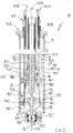
- Fig. 1A is an elevation view of the light signaling device for the bow of a ship according to the present invention, illustrated in a state of rest and without the light signaling means, which is supported fixed at the top thereof;
- Fig. 1B is a similar view to that of Fig. 1A, but in which the device according to the invention is illustrated in operating condition;
- Fig. 2 is an axial sectional view of the device of Fig. 1A, in a different scale and partially broken;
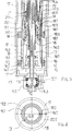
- Fig. 3 is an enlarged view of the lower part of the device of Fig. 2;
- Fig. 4 is a cross-sectional view of the detail of Fig. 3;
- Fig. 5 is an enlarged view of the upper part of the device of Fig. 2.
- With reference to the drawing, the reference numeral 10 (Figs. 1A, 1B, 2) indicates in its entirety the light signaling device for the bow of a ship according to the invention. In the drawing, for simplification, said device is illustrated without the light signaling means, which is supported fixed at the top thereof, and the related electric circuit supply and control means of the light signaling means itself.
- Said
device 10 comprises an outer cylindricaltubular liner 11, which is fixed with axis vertical with respect to the fixed structure of the ship (not illustrated), for example underneath a bridge. Saidliner 11 comprises within a telescopictubular rod 15, to support the light signaling means, and which in Fig. 1A is illustrated retracted and in Fig. 1B extended with respect to theliner 11 itself. - With particular reference to Figs. 2 and 3, said
tubular liner 11, for example made of stainless steel, has a lower cap 11.1 axially perforated and detachably attached to the liner itself. Said cap 11.1 supports, externally, a fixed box 11.2 containing therein, by means of bearing means 11.3, ahelical worm wheel 12, coaxial and rotating freely with respect to saidliner 11. A lower axial end of a firsttubular lead screw 13 with trapezoidal outer thread is fixed coaxial, by means of a key, in saidworm wheel 12 and extends axially along part of the height of saidliner 11. A worm screw 12.1 with an essentially horizontal axis is meshed with respect to saidworm wheel 12 and is kinematically connected with respect to an electrical gear-motor (not illustrated) that sets in rotation, when controlled, said worm screw 12.1 selectively in the two opposite directions of rotation, correspondingly setting in integral rotation saidworm wheel 12 and saidfirst lead screw 13. - A
first nut screw 14, for example made of bronze, is engaged with trapezoidal screw helical fit with saidfirst lead screw 13 and supports a first coaxial fixed annular plate 14.1. - Said first annular plate 14.1 supports a first fixed coaxial bush 14.2, proximal to said
first lead screw 13, and a first fixed telescopic tubular section 15.1 of said telescopictubular rod 15, distal from saidfirst lead screw 13. Said first telescopic tubular section 15.1 is made, for example, of carbon. - A pair of
guide rings 16 are coaxially fixed on the outside surface of said first telescopic tubular section 15.1 and have respective external axial grooves 16.1 (i.e., extending parallel to the axis of the liner 11) aligned with each other and engaged with a corresponding axial linear guide 16.2 attached to the inner surface ofsaid liner 11, for the entire length of the liner itself. By means of this arrangement said first telescopic tubular section 15.1 is translated, in the axial direction, integrally with saidfirst nut screw 14, when saidfirst lead screw 13 is set in rotation, while it is prevented from rotating with the nut screw itself. - Said first bush 14.2 supports a second bush 17.1 coaxial and above, with an intermediate coaxial bearing support 17.2 that allows said second bush 17.1 to rotate independently with respect to said first bush 14.2. Said second bush 17.1 is integral in rotation with respect to said
first lead screw 13 by means of a key 17.3. - In said second bush 17.1 a lower axial end of a
second lead screw 17, is fixed, tubular, external and coaxial with respect to saidfirst lead screw 13. Saidsecond lead screw 17, which has a trapezoidal external thread, extends axially along part of the height of saidliner 11. - Above said second bush 17.1, a
second nut screw 18, for example made of plastic material, is engaged with helical fit with said secondtubular lead screw 17 and supports a second fixed coaxial annular plate 18.1. - Said second annular plate 18.1 supports a third fixed coaxial bush 18.2, proximal to said
second lead screw 17, and a second fixed telescopic tubular section 15.2 of said telescopictubular rod 15, distal from saidsecond lead screw 17. Said second telescopic tubular section 15.2 is made, for example, of carbon. - A pair of
guide rings 19 are coaxially fixed on the outside surface of said second telescopic tubular section 15.2 and have respective external grooves 19.1 axially aligned with each other and engaged with a corresponding axial linear guide 19.2 attached to the inner surface of said first telescopic tubular section 15.1, for the entire length of the tubular section itself. By means of this arrangement, said second telescopic tubular section 15.2 is translated, in the axial direction, integrally with saidsecond nut screw 18, when said secondtubular lead screw 17 is set in rotation integrally with said first lead screw 13 (integral with said second bush 17.1), while it is prevented from rotating with the second nut screw itself. - Said third bush 18.2 supports a fourth bush 20.1 coaxial and above, with an intermediate coaxial bearing support 20.2 that allows said fourth bush 20.1 to rotate independently with respect to said third bush 18.2. Said fourth bush 20.1 is integral in rotation with respect to said
second lead screw 17 by means of a key 20.3. - In said fourth bush 20.1 a lower axial end of a
third lead screw 20, is fixed, tubular, external and coaxial with respect to saidsecond lead screw 17. Saidthird lead screw 20, which has a trapezoidal external thread, extends axially along part of the height of saidliner 11. - Above said fourth bush 20.1, a third nut screw 21, for example made of plastic material, is engaged with helical fit with said third
tubular lead screw 20 and supports a fixed coaxial tubular sleeve 21.1. - Said sleeve 21.1 supports, in turn, a third telescopic tubular section 15.3 of said telescopic
tubular rod 15, coaxial with respect to saidthird lead screw 20. Said third telescopic tubular section 15.3 is made, for example, of carbon. - A pair of
guide rings 22 are coaxially fixed on the outside surface of said third telescopic tubular section 15.3 and have respective external grooves axially aligned with each other and engaged with a corresponding axial linear guide 22.2 attached to the inner surface of said second telescopic tubular section 15.2, for the entire length of the tubular section itself. By means of this arrangement said third telescopic tubular section 15.3 is translated, in the axial direction, integrally with said third nut screw 21, when said thirdtubular lead screw 20 is set in rotation (by means of said fourth bush 20.1 integral with said second lead screw 17) integrally with saidfirst lead screw 13, while it is prevented from rotating with the third nut screw itself. - As is apparent from the above, the light signaling device for the bow of a
ship 10 according to the present invention comprises, within the tubularouter liner 11, a telescopically extensible/retractable rod with three telescopic stages, each of which respectively includes: - a lead screw (13, 17, 20),
- a nut screw (14, 18, 21) engaged with helical fit with said lead screw,
- a corresponding telescopic tubular section (15.1, 15.2, 15.3) connected, by means of respective support means (14.1, 18.1, 21.1), to said nut screw (14, 18, 21) and which is translated, in the axial direction, integrally with said nut screw, when said lead screw is set in rotation, while it is prevented from rotating with the nut screw itself.
- Said lead screws (13, 17, 20) are integral to one another in rotation and receive the motion from electrical gear-motor means by transmission means (12, 12.1) kinematically connected to one (13) of said lead screws.
- Said lead screws (13, 17, 20) are tubular, coaxial and provided with external thread.
- With particular reference to Figs. 2 and 5, said tubular
outer liner 11 has, at the top thereof, an annular cover 11.4, through which the free upper end of said first telescopic section 15.1 is guided by means of corresponding annular sealing means. Said first telescopic section 15.1 has an outer flange 15.10 in the proximity of the upper end that, when said first telescopic section is retracted in theliner 11, rests on said cover 11.4. Moreover, said first telescopic section 15.1 has, at the top thereof, an annular cover 15.11, through which the free upper end of said second telescopic section 15.2 is guided by means of corresponding annular sealing means. - Analogously, said second telescopic section 15.2 has, at the top thereof, an annular cover 15.21, through which the free upper end of said third telescopic section (15.3) is guided by means of corresponding annular sealing means.
- An annular cover 15.30 partially closes the free top of said third telescopic section (15.3) and has an axial through hole (15.31) aligned with the axial cavities of said three
lead screws box 11 has an opening for housing a fixed sleeve 11.5, axially aligned with said hole 15.31 of the cover 15.30. - By means of this arrangement, the
device 10 according to the invention provides a free axial passage way, through thebox 11 and said sleeve 11.5, thelead screws - An automatic winder/unwinder device of electrical cables, know per se and not illustrated, can be provided in proximity of the fixed
box 11, to facilitate the unwinding and rewinding operations of said electrical cables, during the extension/retraction of thetelescopic support rod 15. - The operation of the
light signaling device 10 for the bow of a ship is easily understood. Starting from the condition illustrated in Fig. 1A, in which the three telescopic sections 15.1, 15.2, 15.3 are axially retracted at rest in thetubular liner 11, an operator sets in rotation (by means of corresponding gear-motor means) the worm screw 12.1 and therefore thehelical worm wheel 12 in the direction suitable for extension of said telescopic sections. Consequently, the threelead screws tubular liner 11, with the same pitch, until reaching the operating arrangement, in which the telescopic rod-shapedvertical support 15 is fully extended, as illustrated in Fig. 1B. During the extension of said rod-shapedsupport 15, the electrical cables connected to the light signaling means and related electric circuit supply and control means, are unwound automatically by said winder/unwinder and are arranged along the axial passage way through thebox 11, the lead screws 13, 17, 20, the tubular telescopic sections 15.1, 15.2, 15.3 and the axial hole 15.31 of the cover 15.30. - When the rotation of said gear-motor means is reversed, said tubular telescopic sections 15.1, 15.2, 15.3 of said
telescopic support rod 15 retract within thetubular liner 11, in the condition of Fig. 1A, in which the flange 15.10 and the covers 11.4, 15.11, 15.21 and 15.30, respectively, together with the corresponding sealing gaskets, ensure suitable resistance to atmospheric agents. - As is apparent from the foregoing description, the light signaling device for the bow of a ship according to the present invention allows the objects set forth in the preamble to be achieved in a simple and effective way.
- In fact, the present invention provides a light signaling device for the bow of a ship with a simple, lightweight structure that does not require the use of hydraulic control means.
- Moreover, the present invention consents the production of a signaling device as specified, which provides a direct and convenient passage way for the electrical cables branching off to the light signaling means and related electrical circuits.
Claims (9)
- Light signaling device (10) for the bow of a ship, including, within a tubular outer liner (11), a support rod (15) with multiple telescopically extensible/retractable stages (15.1, 15.2, 15.3), characterized in that each of said telescopically extensible/retractable stages (15.1, 15.2, 15.3) includes, respectively:- a lead screw (13, 17, 20);- a nut screw (14, 18, 21) engaged with helical fit with said lead screw,- a corresponding telescopic tubular section (15.1, 15.2, 15.3) coaxial and connected, by means of respective support means (14.1, 18.1, 21.1), with respect to said nut screw (14, 18, 21) and which translates in the axial direction, integrally with said nut screw, when said lead screw is set in rotation, while it is prevented from rotating with the nut screw itself by means of linear guide means (16, 19, 22; 16.1, 19.1; 16.2, 19.2, 22.2);in that said lead screws (13, 17, 20) are integral to one another in rotation and receive the motion from electrical gear-motor means by transmission means (12, 12.1) kinematically connected to one (13) of said lead screws, and in that said lead screws (13, 17, 20) are tubular, coaxial and provided with external thread.
- Light signaling device (10) according to claim 1, characterized in that it comprises a first nut screw (14) engaged with helical fit with a first tubular lead screw (13) and supports first bush means (14.2), which support second coaxial bush means (17.1), with intermediate coaxial bearing support means (17.2), and are integral in rotation with respect to said first lead screw (13), and in that in said second bush means (17.1), a lower axial end of a second lead screw (17) is fixed, tubular, outer and coaxial with respect to said first lead screw (13) and engaged with helical fit with a second nut screw (18).
- Light signaling device (10) according to claim 2, characterized in that said second nut screw (18) supports third bush means (18.2), which support fourth coaxial bush means (20.1), with an intermediate coaxial bearing support (20.2), and integral in rotation with respect to said second lead screw (17), and in that in said fourth bush means (20.1), a lower axial end of a third lead screw (20) is fixed, tubular, outer and coaxial with respect to said second lead screw (17) and engaged with helical fit with a third nut screw (21).
- Light signaling device (10) according to claim 2, characterized in that said first nut screw (14) supports a first fixed telescopic tubular section (15.1).
- Light signaling device (10) according to claim 2 and/or 3, characterized in that said second nut screw (18) supports a second fixed telescopic tubular section (15.2).
- Light signaling device (10) according to claim 3, characterized in that said third nut screw (21) supports a third fixed telescopic tubular section (15.3).
- Signaling device (10) according to claim 1, characterized in that said linear guide means (16, 19, 22; 16.1, 19.1; 16.2, 19.2;, 22.2) comprise of guide rings (16, 19, 22) coaxially fixed on the outside surface of a respective telescopic tubular section (15.1, 15.2, 15.3) and presenting respective external grooves (16.1, 19.1) axially aligned with each other and engaged with corresponding axial linear guide means (16.2 , 19.2, 22.2) attached to the inner surface of said liner (11), respectively of the adjacent telescopic tubular section (15.1, 15.2).
- Light signaling device (10) according to one or more of the preceding claims, characterized in that:- said tubular outer liner (11) has, at the top thereof, an annular cover (11.4), through which the free upper end of said first telescopic section (15.1) is guided by means of corresponding annular sealing means;- said first telescopic section (15.1) has, at the top thereof, an annular cover (15.11), through which the free upper end of said second telescopic section (15.2) is guided by means of corresponding annular sealing means;- said second telescopic section (15.2) has, at the top thereof, an annular cover (15.21), through which the free upper end of said third telescopic section (15.3) is guided by means of corresponding annular sealing means;- an annular cover (15.30) partially closes the free top of said third telescopic section (15.3) and has an axial through hole (15.31) aligned with the axial cavities of said lead screws (13, 17, 20),and in that said device (10) comprises a free axial passage way provided through said lead screws (13, 17, 20), said telescopic tubular sections (15.1, 15.2, 15.3) and said axial hole (15.31) of the cover (15.30), for electric cables, branching off to the light signaling means and related electric circuit supply and control means.
- Light signaling device (10) according to claim 8, characterized in that said first telescopic section (15.1) has an outer flange (15.10) in the proximity of the upper end.
Applications Claiming Priority (1)
| Application Number | Priority Date | Filing Date | Title |
|---|---|---|---|
| IT102016000114853A IT201600114853A1 (en) | 2016-11-14 | 2016-11-14 | LUMINOUS SIGNALING DEVICE FOR SHIP BOW |
Publications (2)
| Publication Number | Publication Date |
|---|---|
| EP3321164A1 true EP3321164A1 (en) | 2018-05-16 |
| EP3321164B1 EP3321164B1 (en) | 2022-06-29 |
Family
ID=58670132
Family Applications (1)
| Application Number | Title | Priority Date | Filing Date |
|---|---|---|---|
| EP17001823.8A Active EP3321164B1 (en) | 2016-11-14 | 2017-11-08 | Light signaling device for the bow of a ship |
Country Status (2)
| Country | Link |
|---|---|
| EP (1) | EP3321164B1 (en) |
| IT (1) | IT201600114853A1 (en) |
Cited By (2)
| Publication number | Priority date | Publication date | Assignee | Title |
|---|---|---|---|---|
| IT202000014479A1 (en) * | 2020-06-17 | 2021-12-17 | Ams Advanced Mech Solutions | CONNECTION JOINT FOR TELESCOPIC SUPPORT AND TELESCOPIC SUPPORT INCLUDING THIS CONNECTION JOINT |
| IT202300013737A1 (en) * | 2023-06-30 | 2024-12-30 | Setec | BOW LIGHT SIGNALLING DEVICE OF A SHIP |
Citations (4)
| Publication number | Priority date | Publication date | Assignee | Title |
|---|---|---|---|---|
| US1212968A (en) * | 1916-02-28 | 1917-01-16 | Orin P Lively | Telescopic mast. |
| DE202011050508U1 (en) * | 2011-06-21 | 2011-08-24 | Federal Signal Vama, S.A. | Telescopic mast for priority signaling |
| US20130039081A1 (en) * | 2011-08-10 | 2013-02-14 | R & D Shed, L.L.C. | Retractable boat light |
| WO2013131844A1 (en) * | 2012-03-08 | 2013-09-12 | Maillard Arnaud | Device for signalling a boat to the mooring |
-
2016
- 2016-11-14 IT IT102016000114853A patent/IT201600114853A1/en unknown
-
2017
- 2017-11-08 EP EP17001823.8A patent/EP3321164B1/en active Active
Patent Citations (4)
| Publication number | Priority date | Publication date | Assignee | Title |
|---|---|---|---|---|
| US1212968A (en) * | 1916-02-28 | 1917-01-16 | Orin P Lively | Telescopic mast. |
| DE202011050508U1 (en) * | 2011-06-21 | 2011-08-24 | Federal Signal Vama, S.A. | Telescopic mast for priority signaling |
| US20130039081A1 (en) * | 2011-08-10 | 2013-02-14 | R & D Shed, L.L.C. | Retractable boat light |
| WO2013131844A1 (en) * | 2012-03-08 | 2013-09-12 | Maillard Arnaud | Device for signalling a boat to the mooring |
Cited By (3)
| Publication number | Priority date | Publication date | Assignee | Title |
|---|---|---|---|---|
| IT202000014479A1 (en) * | 2020-06-17 | 2021-12-17 | Ams Advanced Mech Solutions | CONNECTION JOINT FOR TELESCOPIC SUPPORT AND TELESCOPIC SUPPORT INCLUDING THIS CONNECTION JOINT |
| IT202300013737A1 (en) * | 2023-06-30 | 2024-12-30 | Setec | BOW LIGHT SIGNALLING DEVICE OF A SHIP |
| EP4488573A1 (en) | 2023-06-30 | 2025-01-08 | SETEC S.p.A. | Light signalling device for the bow of a ship |
Also Published As
| Publication number | Publication date |
|---|---|
| IT201600114853A1 (en) | 2018-05-14 |
| EP3321164B1 (en) | 2022-06-29 |
Similar Documents
| Publication | Publication Date | Title |
|---|---|---|
| US9091334B2 (en) | Linear actuator and height-adjustable table | |
| US4337868A (en) | Telescopic crane boom having rotatable extend/retract screws | |
| EP3321164B1 (en) | Light signaling device for the bow of a ship | |
| JP6576464B2 (en) | 4-stage telescope actuator with screw drive mechanism | |
| EP2301382A1 (en) | Telescopic column for height adjustment | |
| US8944467B1 (en) | Automated RV landing gear | |
| US20110174101A1 (en) | Height-adjustable actuation device | |
| WO2006098739A3 (en) | Heavy duty field mast | |
| ATE522766T1 (en) | MOVABLE MULTI-DIRECTIONAL LIGHT STAND | |
| US2926867A (en) | Winch | |
| CN207668541U (en) | A kind of mechanical expanding shaft | |
| CN209797162U (en) | Clamping structure of communication cable retractable device for communication engineering | |
| EP3614884B1 (en) | A telescopic column for height-adjustable furniture | |
| CN208010904U (en) | A kind of push rod nut-screw fixation lubricating structure | |
| CN103358274B (en) | Dedicated tool for oil seal assembly | |
| CN104917084A (en) | Insulated operating lever with lighting | |
| EP4488573B1 (en) | Light signalling device for the bow of a ship | |
| US1868478A (en) | Lifting jack | |
| NO20064571L (en) | Regulation of telescopic moving element | |
| US2326443A (en) | Automobile radio antenna | |
| US3069180A (en) | Seal construction | |
| RU2012141734A (en) | ROTARY SUPPORT | |
| US2155157A (en) | Bumper type auto jack | |
| EP3821137B1 (en) | Piston-cylinder unit for a working machine | |
| CN204074814U (en) | Admission machine |
Legal Events
| Date | Code | Title | Description |
|---|---|---|---|
| PUAI | Public reference made under article 153(3) epc to a published international application that has entered the european phase |
Free format text: ORIGINAL CODE: 0009012 |
|
| STAA | Information on the status of an ep patent application or granted ep patent |
Free format text: STATUS: THE APPLICATION HAS BEEN PUBLISHED |
|
| AK | Designated contracting states |
Kind code of ref document: A1 Designated state(s): AL AT BE BG CH CY CZ DE DK EE ES FI FR GB GR HR HU IE IS IT LI LT LU LV MC MK MT NL NO PL PT RO RS SE SI SK SM TR |
|
| AX | Request for extension of the european patent |
Extension state: BA ME |
|
| STAA | Information on the status of an ep patent application or granted ep patent |
Free format text: STATUS: REQUEST FOR EXAMINATION WAS MADE |
|
| 17P | Request for examination filed |
Effective date: 20181112 |
|
| RBV | Designated contracting states (corrected) |
Designated state(s): AL AT BE BG CH CY CZ DE DK EE ES FI FR GB GR HR HU IE IS IT LI LT LU LV MC MK MT NL NO PL PT RO RS SE SI SK SM TR |
|
| STAA | Information on the status of an ep patent application or granted ep patent |
Free format text: STATUS: EXAMINATION IS IN PROGRESS |
|
| 17Q | First examination report despatched |
Effective date: 20201021 |
|
| GRAP | Despatch of communication of intention to grant a patent |
Free format text: ORIGINAL CODE: EPIDOSNIGR1 |
|
| STAA | Information on the status of an ep patent application or granted ep patent |
Free format text: STATUS: GRANT OF PATENT IS INTENDED |
|
| INTG | Intention to grant announced |
Effective date: 20211110 |
|
| GRAS | Grant fee paid |
Free format text: ORIGINAL CODE: EPIDOSNIGR3 |
|
| GRAA | (expected) grant |
Free format text: ORIGINAL CODE: 0009210 |
|
| STAA | Information on the status of an ep patent application or granted ep patent |
Free format text: STATUS: THE PATENT HAS BEEN GRANTED |
|
| AK | Designated contracting states |
Kind code of ref document: B1 Designated state(s): AL AT BE BG CH CY CZ DE DK EE ES FI FR GB GR HR HU IE IS IT LI LT LU LV MC MK MT NL NO PL PT RO RS SE SI SK SM TR |
|
| REG | Reference to a national code |
Ref country code: CH Ref legal event code: EP |
|
| REG | Reference to a national code |
Ref country code: AT Ref legal event code: REF Ref document number: 1501190 Country of ref document: AT Kind code of ref document: T Effective date: 20220715 |
|
| REG | Reference to a national code |
Ref country code: IE Ref legal event code: FG4D |
|
| REG | Reference to a national code |
Ref country code: DE Ref legal event code: R096 Ref document number: 602017058922 Country of ref document: DE |
|
| REG | Reference to a national code |
Ref country code: NL Ref legal event code: FP |
|
| REG | Reference to a national code |
Ref country code: LT Ref legal event code: MG9D |
|
| PG25 | Lapsed in a contracting state [announced via postgrant information from national office to epo] |
Ref country code: SE Free format text: LAPSE BECAUSE OF FAILURE TO SUBMIT A TRANSLATION OF THE DESCRIPTION OR TO PAY THE FEE WITHIN THE PRESCRIBED TIME-LIMIT Effective date: 20220629 Ref country code: NO Free format text: LAPSE BECAUSE OF FAILURE TO SUBMIT A TRANSLATION OF THE DESCRIPTION OR TO PAY THE FEE WITHIN THE PRESCRIBED TIME-LIMIT Effective date: 20220929 Ref country code: LT Free format text: LAPSE BECAUSE OF FAILURE TO SUBMIT A TRANSLATION OF THE DESCRIPTION OR TO PAY THE FEE WITHIN THE PRESCRIBED TIME-LIMIT Effective date: 20220629 Ref country code: HR Free format text: LAPSE BECAUSE OF FAILURE TO SUBMIT A TRANSLATION OF THE DESCRIPTION OR TO PAY THE FEE WITHIN THE PRESCRIBED TIME-LIMIT Effective date: 20220629 Ref country code: GR Free format text: LAPSE BECAUSE OF FAILURE TO SUBMIT A TRANSLATION OF THE DESCRIPTION OR TO PAY THE FEE WITHIN THE PRESCRIBED TIME-LIMIT Effective date: 20220930 Ref country code: FI Free format text: LAPSE BECAUSE OF FAILURE TO SUBMIT A TRANSLATION OF THE DESCRIPTION OR TO PAY THE FEE WITHIN THE PRESCRIBED TIME-LIMIT Effective date: 20220629 Ref country code: BG Free format text: LAPSE BECAUSE OF FAILURE TO SUBMIT A TRANSLATION OF THE DESCRIPTION OR TO PAY THE FEE WITHIN THE PRESCRIBED TIME-LIMIT Effective date: 20220929 |
|
| REG | Reference to a national code |
Ref country code: AT Ref legal event code: MK05 Ref document number: 1501190 Country of ref document: AT Kind code of ref document: T Effective date: 20220629 |
|
| PG25 | Lapsed in a contracting state [announced via postgrant information from national office to epo] |
Ref country code: RS Free format text: LAPSE BECAUSE OF FAILURE TO SUBMIT A TRANSLATION OF THE DESCRIPTION OR TO PAY THE FEE WITHIN THE PRESCRIBED TIME-LIMIT Effective date: 20220629 Ref country code: LV Free format text: LAPSE BECAUSE OF FAILURE TO SUBMIT A TRANSLATION OF THE DESCRIPTION OR TO PAY THE FEE WITHIN THE PRESCRIBED TIME-LIMIT Effective date: 20220629 |
|
| PG25 | Lapsed in a contracting state [announced via postgrant information from national office to epo] |
Ref country code: SM Free format text: LAPSE BECAUSE OF FAILURE TO SUBMIT A TRANSLATION OF THE DESCRIPTION OR TO PAY THE FEE WITHIN THE PRESCRIBED TIME-LIMIT Effective date: 20220629 Ref country code: SK Free format text: LAPSE BECAUSE OF FAILURE TO SUBMIT A TRANSLATION OF THE DESCRIPTION OR TO PAY THE FEE WITHIN THE PRESCRIBED TIME-LIMIT Effective date: 20220629 Ref country code: RO Free format text: LAPSE BECAUSE OF FAILURE TO SUBMIT A TRANSLATION OF THE DESCRIPTION OR TO PAY THE FEE WITHIN THE PRESCRIBED TIME-LIMIT Effective date: 20220629 Ref country code: PT Free format text: LAPSE BECAUSE OF FAILURE TO SUBMIT A TRANSLATION OF THE DESCRIPTION OR TO PAY THE FEE WITHIN THE PRESCRIBED TIME-LIMIT Effective date: 20221031 Ref country code: ES Free format text: LAPSE BECAUSE OF FAILURE TO SUBMIT A TRANSLATION OF THE DESCRIPTION OR TO PAY THE FEE WITHIN THE PRESCRIBED TIME-LIMIT Effective date: 20220629 Ref country code: EE Free format text: LAPSE BECAUSE OF FAILURE TO SUBMIT A TRANSLATION OF THE DESCRIPTION OR TO PAY THE FEE WITHIN THE PRESCRIBED TIME-LIMIT Effective date: 20220629 Ref country code: AT Free format text: LAPSE BECAUSE OF FAILURE TO SUBMIT A TRANSLATION OF THE DESCRIPTION OR TO PAY THE FEE WITHIN THE PRESCRIBED TIME-LIMIT Effective date: 20220629 |
|
| PG25 | Lapsed in a contracting state [announced via postgrant information from national office to epo] |
Ref country code: PL Free format text: LAPSE BECAUSE OF FAILURE TO SUBMIT A TRANSLATION OF THE DESCRIPTION OR TO PAY THE FEE WITHIN THE PRESCRIBED TIME-LIMIT Effective date: 20220629 Ref country code: IS Free format text: LAPSE BECAUSE OF FAILURE TO SUBMIT A TRANSLATION OF THE DESCRIPTION OR TO PAY THE FEE WITHIN THE PRESCRIBED TIME-LIMIT Effective date: 20221029 |
|
| REG | Reference to a national code |
Ref country code: DE Ref legal event code: R097 Ref document number: 602017058922 Country of ref document: DE |
|
| PG25 | Lapsed in a contracting state [announced via postgrant information from national office to epo] |
Ref country code: AL Free format text: LAPSE BECAUSE OF FAILURE TO SUBMIT A TRANSLATION OF THE DESCRIPTION OR TO PAY THE FEE WITHIN THE PRESCRIBED TIME-LIMIT Effective date: 20220629 |
|
| PG25 | Lapsed in a contracting state [announced via postgrant information from national office to epo] |
Ref country code: DK Free format text: LAPSE BECAUSE OF FAILURE TO SUBMIT A TRANSLATION OF THE DESCRIPTION OR TO PAY THE FEE WITHIN THE PRESCRIBED TIME-LIMIT Effective date: 20220629 Ref country code: CZ Free format text: LAPSE BECAUSE OF FAILURE TO SUBMIT A TRANSLATION OF THE DESCRIPTION OR TO PAY THE FEE WITHIN THE PRESCRIBED TIME-LIMIT Effective date: 20220629 |
|
| PLBE | No opposition filed within time limit |
Free format text: ORIGINAL CODE: 0009261 |
|
| STAA | Information on the status of an ep patent application or granted ep patent |
Free format text: STATUS: NO OPPOSITION FILED WITHIN TIME LIMIT |
|
| 26N | No opposition filed |
Effective date: 20230330 |
|
| PG25 | Lapsed in a contracting state [announced via postgrant information from national office to epo] |
Ref country code: MC Free format text: LAPSE BECAUSE OF FAILURE TO SUBMIT A TRANSLATION OF THE DESCRIPTION OR TO PAY THE FEE WITHIN THE PRESCRIBED TIME-LIMIT Effective date: 20220629 |
|
| REG | Reference to a national code |
Ref country code: CH Ref legal event code: PL |
|
| GBPC | Gb: european patent ceased through non-payment of renewal fee |
Effective date: 20221108 |
|
| REG | Reference to a national code |
Ref country code: BE Ref legal event code: MM Effective date: 20221130 |
|
| PG25 | Lapsed in a contracting state [announced via postgrant information from national office to epo] |
Ref country code: LI Free format text: LAPSE BECAUSE OF NON-PAYMENT OF DUE FEES Effective date: 20221130 Ref country code: CH Free format text: LAPSE BECAUSE OF NON-PAYMENT OF DUE FEES Effective date: 20221130 |
|
| PG25 | Lapsed in a contracting state [announced via postgrant information from national office to epo] |
Ref country code: SI Free format text: LAPSE BECAUSE OF FAILURE TO SUBMIT A TRANSLATION OF THE DESCRIPTION OR TO PAY THE FEE WITHIN THE PRESCRIBED TIME-LIMIT Effective date: 20220629 Ref country code: LU Free format text: LAPSE BECAUSE OF NON-PAYMENT OF DUE FEES Effective date: 20221108 |
|
| PG25 | Lapsed in a contracting state [announced via postgrant information from national office to epo] |
Ref country code: IE Free format text: LAPSE BECAUSE OF NON-PAYMENT OF DUE FEES Effective date: 20221108 Ref country code: GB Free format text: LAPSE BECAUSE OF NON-PAYMENT OF DUE FEES Effective date: 20221108 |
|
| PG25 | Lapsed in a contracting state [announced via postgrant information from national office to epo] |
Ref country code: BE Free format text: LAPSE BECAUSE OF NON-PAYMENT OF DUE FEES Effective date: 20221130 |
|
| PG25 | Lapsed in a contracting state [announced via postgrant information from national office to epo] |
Ref country code: IT Free format text: LAPSE BECAUSE OF FAILURE TO SUBMIT A TRANSLATION OF THE DESCRIPTION OR TO PAY THE FEE WITHIN THE PRESCRIBED TIME-LIMIT Effective date: 20220629 |
|
| PG25 | Lapsed in a contracting state [announced via postgrant information from national office to epo] |
Ref country code: HU Free format text: LAPSE BECAUSE OF FAILURE TO SUBMIT A TRANSLATION OF THE DESCRIPTION OR TO PAY THE FEE WITHIN THE PRESCRIBED TIME-LIMIT; INVALID AB INITIO Effective date: 20171108 |
|
| PG25 | Lapsed in a contracting state [announced via postgrant information from national office to epo] |
Ref country code: CY Free format text: LAPSE BECAUSE OF FAILURE TO SUBMIT A TRANSLATION OF THE DESCRIPTION OR TO PAY THE FEE WITHIN THE PRESCRIBED TIME-LIMIT Effective date: 20220629 |
|
| PG25 | Lapsed in a contracting state [announced via postgrant information from national office to epo] |
Ref country code: MK Free format text: LAPSE BECAUSE OF FAILURE TO SUBMIT A TRANSLATION OF THE DESCRIPTION OR TO PAY THE FEE WITHIN THE PRESCRIBED TIME-LIMIT Effective date: 20220629 |
|
| PG25 | Lapsed in a contracting state [announced via postgrant information from national office to epo] |
Ref country code: MT Free format text: LAPSE BECAUSE OF FAILURE TO SUBMIT A TRANSLATION OF THE DESCRIPTION OR TO PAY THE FEE WITHIN THE PRESCRIBED TIME-LIMIT Effective date: 20220629 |
|
| PG25 | Lapsed in a contracting state [announced via postgrant information from national office to epo] |
Ref country code: BG Free format text: LAPSE BECAUSE OF FAILURE TO SUBMIT A TRANSLATION OF THE DESCRIPTION OR TO PAY THE FEE WITHIN THE PRESCRIBED TIME-LIMIT Effective date: 20220629 |
|
| PG25 | Lapsed in a contracting state [announced via postgrant information from national office to epo] |
Ref country code: BG Free format text: LAPSE BECAUSE OF FAILURE TO SUBMIT A TRANSLATION OF THE DESCRIPTION OR TO PAY THE FEE WITHIN THE PRESCRIBED TIME-LIMIT Effective date: 20220629 |
|
| PGFP | Annual fee paid to national office [announced via postgrant information from national office to epo] |
Ref country code: NL Payment date: 20251128 Year of fee payment: 9 |
|
| PGFP | Annual fee paid to national office [announced via postgrant information from national office to epo] |
Ref country code: FR Payment date: 20251128 Year of fee payment: 9 |
|
| PGFP | Annual fee paid to national office [announced via postgrant information from national office to epo] |
Ref country code: TR Payment date: 20251204 Year of fee payment: 9 |
|
| PGFP | Annual fee paid to national office [announced via postgrant information from national office to epo] |
Ref country code: DE Payment date: 20251231 Year of fee payment: 9 |