EP3321029A1 - Damper for machining processes - Google Patents
Damper for machining processes Download PDFInfo
- Publication number
- EP3321029A1 EP3321029A1 EP17199768.7A EP17199768A EP3321029A1 EP 3321029 A1 EP3321029 A1 EP 3321029A1 EP 17199768 A EP17199768 A EP 17199768A EP 3321029 A1 EP3321029 A1 EP 3321029A1
- Authority
- EP
- European Patent Office
- Prior art keywords
- damper
- workpiece
- nodes
- airfoil
- damping material
- Prior art date
- Legal status (The legal status is an assumption and is not a legal conclusion. Google has not performed a legal analysis and makes no representation as to the accuracy of the status listed.)
- Granted
Links
Images




Classifications
-
- F—MECHANICAL ENGINEERING; LIGHTING; HEATING; WEAPONS; BLASTING
- F16—ENGINEERING ELEMENTS AND UNITS; GENERAL MEASURES FOR PRODUCING AND MAINTAINING EFFECTIVE FUNCTIONING OF MACHINES OR INSTALLATIONS; THERMAL INSULATION IN GENERAL
- F16F—SPRINGS; SHOCK-ABSORBERS; MEANS FOR DAMPING VIBRATION
- F16F7/00—Vibration-dampers; Shock-absorbers
- F16F7/10—Vibration-dampers; Shock-absorbers using inertia effect
-
- F—MECHANICAL ENGINEERING; LIGHTING; HEATING; WEAPONS; BLASTING
- F16—ENGINEERING ELEMENTS AND UNITS; GENERAL MEASURES FOR PRODUCING AND MAINTAINING EFFECTIVE FUNCTIONING OF MACHINES OR INSTALLATIONS; THERMAL INSULATION IN GENERAL
- F16F—SPRINGS; SHOCK-ABSORBERS; MEANS FOR DAMPING VIBRATION
- F16F7/00—Vibration-dampers; Shock-absorbers
- F16F7/01—Vibration-dampers; Shock-absorbers using friction between loose particles, e.g. sand
- F16F7/015—Vibration-dampers; Shock-absorbers using friction between loose particles, e.g. sand the particles being spherical, cylindrical or the like
-
- B—PERFORMING OPERATIONS; TRANSPORTING
- B23—MACHINE TOOLS; METAL-WORKING NOT OTHERWISE PROVIDED FOR
- B23C—MILLING
- B23C3/00—Milling particular work; Special milling operations; Machines therefor
-
- B—PERFORMING OPERATIONS; TRANSPORTING
- B23—MACHINE TOOLS; METAL-WORKING NOT OTHERWISE PROVIDED FOR
- B23Q—DETAILS, COMPONENTS, OR ACCESSORIES FOR MACHINE TOOLS, e.g. ARRANGEMENTS FOR COPYING OR CONTROLLING; MACHINE TOOLS IN GENERAL CHARACTERISED BY THE CONSTRUCTION OF PARTICULAR DETAILS OR COMPONENTS; COMBINATIONS OR ASSOCIATIONS OF METAL-WORKING MACHINES, NOT DIRECTED TO A PARTICULAR RESULT
- B23Q11/00—Accessories fitted to machine tools for keeping tools or parts of the machine in good working condition or for cooling work; Safety devices specially combined with or arranged in, or specially adapted for use in connection with, machine tools
- B23Q11/0032—Arrangements for preventing or isolating vibrations in parts of the machine
-
- B—PERFORMING OPERATIONS; TRANSPORTING
- B23—MACHINE TOOLS; METAL-WORKING NOT OTHERWISE PROVIDED FOR
- B23Q—DETAILS, COMPONENTS, OR ACCESSORIES FOR MACHINE TOOLS, e.g. ARRANGEMENTS FOR COPYING OR CONTROLLING; MACHINE TOOLS IN GENERAL CHARACTERISED BY THE CONSTRUCTION OF PARTICULAR DETAILS OR COMPONENTS; COMBINATIONS OR ASSOCIATIONS OF METAL-WORKING MACHINES, NOT DIRECTED TO A PARTICULAR RESULT
- B23Q3/00—Devices holding, supporting, or positioning work or tools, of a kind normally removable from the machine
- B23Q3/02—Devices holding, supporting, or positioning work or tools, of a kind normally removable from the machine for mounting on a work-table, tool-slide, or analogous part
- B23Q3/06—Work-clamping means
- B23Q3/062—Work-clamping means adapted for holding workpieces having a special form or being made from a special material
- B23Q3/065—Work-clamping means adapted for holding workpieces having a special form or being made from a special material for holding workpieces being specially deformable, e.g. made from thin-walled or elastic material
-
- F—MECHANICAL ENGINEERING; LIGHTING; HEATING; WEAPONS; BLASTING
- F01—MACHINES OR ENGINES IN GENERAL; ENGINE PLANTS IN GENERAL; STEAM ENGINES
- F01D—NON-POSITIVE DISPLACEMENT MACHINES OR ENGINES, e.g. STEAM TURBINES
- F01D5/00—Blades; Blade-carrying members; Heating, heat-insulating, cooling or antivibration means on the blades or the members
- F01D5/12—Blades
- F01D5/14—Form or construction
- F01D5/16—Form or construction for counteracting blade vibration
-
- F—MECHANICAL ENGINEERING; LIGHTING; HEATING; WEAPONS; BLASTING
- F16—ENGINEERING ELEMENTS AND UNITS; GENERAL MEASURES FOR PRODUCING AND MAINTAINING EFFECTIVE FUNCTIONING OF MACHINES OR INSTALLATIONS; THERMAL INSULATION IN GENERAL
- F16F—SPRINGS; SHOCK-ABSORBERS; MEANS FOR DAMPING VIBRATION
- F16F1/00—Springs
- F16F1/36—Springs made of rubber or other material having high internal friction, e.g. thermoplastic elastomers
- F16F1/373—Springs made of rubber or other material having high internal friction, e.g. thermoplastic elastomers characterised by having a particular shape
- F16F1/3737—Planar, e.g. in sheet form
-
- F—MECHANICAL ENGINEERING; LIGHTING; HEATING; WEAPONS; BLASTING
- F16—ENGINEERING ELEMENTS AND UNITS; GENERAL MEASURES FOR PRODUCING AND MAINTAINING EFFECTIVE FUNCTIONING OF MACHINES OR INSTALLATIONS; THERMAL INSULATION IN GENERAL
- F16F—SPRINGS; SHOCK-ABSORBERS; MEANS FOR DAMPING VIBRATION
- F16F7/00—Vibration-dampers; Shock-absorbers
- F16F7/10—Vibration-dampers; Shock-absorbers using inertia effect
- F16F7/1034—Vibration-dampers; Shock-absorbers using inertia effect of movement of a liquid
-
- B—PERFORMING OPERATIONS; TRANSPORTING
- B23—MACHINE TOOLS; METAL-WORKING NOT OTHERWISE PROVIDED FOR
- B23C—MILLING
- B23C2215/00—Details of workpieces
- B23C2215/04—Aircraft components
-
- B—PERFORMING OPERATIONS; TRANSPORTING
- B23—MACHINE TOOLS; METAL-WORKING NOT OTHERWISE PROVIDED FOR
- B23C—MILLING
- B23C2215/00—Details of workpieces
- B23C2215/44—Turbine blades
-
- B—PERFORMING OPERATIONS; TRANSPORTING
- B23—MACHINE TOOLS; METAL-WORKING NOT OTHERWISE PROVIDED FOR
- B23C—MILLING
- B23C2220/00—Details of milling processes
- B23C2220/60—Roughing
- B23C2220/605—Roughing and finishing
-
- B—PERFORMING OPERATIONS; TRANSPORTING
- B23—MACHINE TOOLS; METAL-WORKING NOT OTHERWISE PROVIDED FOR
- B23C—MILLING
- B23C2250/00—Compensating adverse effects during milling
- B23C2250/16—Damping vibrations
-
- F—MECHANICAL ENGINEERING; LIGHTING; HEATING; WEAPONS; BLASTING
- F16—ENGINEERING ELEMENTS AND UNITS; GENERAL MEASURES FOR PRODUCING AND MAINTAINING EFFECTIVE FUNCTIONING OF MACHINES OR INSTALLATIONS; THERMAL INSULATION IN GENERAL
- F16F—SPRINGS; SHOCK-ABSORBERS; MEANS FOR DAMPING VIBRATION
- F16F2224/00—Materials; Material properties
- F16F2224/02—Materials; Material properties solids
-
- F—MECHANICAL ENGINEERING; LIGHTING; HEATING; WEAPONS; BLASTING
- F16—ENGINEERING ELEMENTS AND UNITS; GENERAL MEASURES FOR PRODUCING AND MAINTAINING EFFECTIVE FUNCTIONING OF MACHINES OR INSTALLATIONS; THERMAL INSULATION IN GENERAL
- F16F—SPRINGS; SHOCK-ABSORBERS; MEANS FOR DAMPING VIBRATION
- F16F2224/00—Materials; Material properties
- F16F2224/02—Materials; Material properties solids
- F16F2224/0208—Alloys
-
- F—MECHANICAL ENGINEERING; LIGHTING; HEATING; WEAPONS; BLASTING
- F16—ENGINEERING ELEMENTS AND UNITS; GENERAL MEASURES FOR PRODUCING AND MAINTAINING EFFECTIVE FUNCTIONING OF MACHINES OR INSTALLATIONS; THERMAL INSULATION IN GENERAL
- F16F—SPRINGS; SHOCK-ABSORBERS; MEANS FOR DAMPING VIBRATION
- F16F2224/00—Materials; Material properties
- F16F2224/04—Fluids
-
- F—MECHANICAL ENGINEERING; LIGHTING; HEATING; WEAPONS; BLASTING
- F16—ENGINEERING ELEMENTS AND UNITS; GENERAL MEASURES FOR PRODUCING AND MAINTAINING EFFECTIVE FUNCTIONING OF MACHINES OR INSTALLATIONS; THERMAL INSULATION IN GENERAL
- F16F—SPRINGS; SHOCK-ABSORBERS; MEANS FOR DAMPING VIBRATION
- F16F2234/00—Shape
- F16F2234/06—Shape plane or flat
Definitions
- the present invention relates to dampers, and in particular, to a damper for machining operations.
- Machining processes include a wide variety of manufacturing processes that are used to form a workpiece from raw material.
- An example of a machining process includes a milling process. Milling processes move a cutting tool across a workpiece to remove material from the workpiece.
- Chattering is rapid vibrations caused by machining processes. In milling processes, specifically, the interrupted cutting action of the cutting tool causes the chattering in the workpiece. Chattering produces waviness on the machined surface, a poor surface finish, and profile errors in the workpiece. Chattering can also result in delamination of composite workpieces.
- Dampers can be used to dampen chattering during machining processes. Numerous damping solutions that exist face challenges.
- a first damping solution is to create a flexible damping sheet to support the workpiece, however flexible damping sheets are typically only effective over a narrow range of frequencies. This limits the speed at which the cutting tool can be turned and restricts the flutes on the cutting tool to avoid reaching frequencies outside of the range covered by the flexible damping sheet.
- a second damping solution is to use an elastomeric damper that can be attached to a workpiece, however the effectiveness of elastomeric dampers decreases as they age and can vary with temperature changes.
- a third damping solution is to fabricate complex fixtures to support and hold workpieces, however custom, complex fixtures can be expensive to produce.
- a damper includes a damper body that is configured to be attached to a workpiece during a machining process.
- a first side of the damper body is configured to abut a first side of the workpiece.
- the damper body includes a frame forming an outer periphery of the damper body, a plurality of damper nodes with a cavity in each damper node positioned in the frame, and a plurality of ribs extending between the frame and the damper nodes.
- a damping material is positioned in the cavity of each damper node.
- a machining system includes a machine having a first clamp, a second clamp, and a cutting tool.
- a workpiece is positioned in the machine.
- a first end of the workpiece is held in the first clamp of the machine and a second end of the workpiece is held in the second clamp of the machine.
- a damper is attached to the workpiece.
- the damper includes a damper body with a first surface that abuts against and conforms to the workpiece.
- the damper body has a frame forming an outer periphery of the damper body, a plurality of damper nodes with a cavity in each of the damper nodes, and a plurality of ribs extending from the frame to the damper nodes.
- a damping material is positioned in the cavity of each damper node.
- a method of machining a workpiece includes positioning a workpiece in a machine.
- the workpiece is rough machined.
- a damper is attached to the workpiece.
- the damper has a damper body with a first surface that abuts against and conforms to the workpiece.
- the damper body has a frame forming an outer periphery of the damper body, a plurality of damper nodes with a cavity in each of the damper nodes, and a plurality of ribs extending from the frame to the damper nodes.
- the workpiece is finish machined. Vibrations in the workpiece are dampened with a damping material in the damper nodes of the damper.
- a damper that can be attached to a workpiece during machining processes to dampen vibrations associated with the machining processes.
- the damper can be manufactured using an additive manufacturing process or a three-dimensional (3D) printing process, which allows the damper to be easily and quickly manufactured. Further, the damper can be designed to accommodate a particular workpiece and easily modified if the design of the workpiece is changed.
- the damper includes damper nodes that have cavities that are filled with a damping material to dampen vibrations from the machining process.
- the damping material in the damper can be a particle damping material or a liquid damping material. The type, size, shape, and volume of damping material that is used can be specifically selected to accommodate each particular workpiece.
- FIGS. 1A-1B show damper 20 attached to airfoil 10.
- FIG. 1A is a perspective view of a first side of damper 20 attached to airfoil 10.
- FIG. 1B is a perspective view of a second side of damper 20 attached to airfoil 10.
- Airfoil 10 includes tip 12, root 14, first surface 16, and second surface 18.
- Damper 20 includes body 22, first surface 24, second surface 26, attachment mechanisms 28, frame 30, first side 32, second side 34, third side 36, fourth side 38, attachment nodes 40, damper nodes 42, ribs 44, openings 46, cavities 48, and damping material 50.
- Airfoil 10 has tip 12 at a first end and root 14 at a second end. First surface 16 of airfoil 10 extends from root 14 to tip 12. Second surface 18 of airfoil 10 is opposite of first surface 16 of airfoil 10 and extends from root 14 to tip 12. Airfoil 10 is a workpiece that is to be machined in the embodiment shown in FIGS. 1A-1B . Airfoil 10 can be made out of aluminum and can be between 2 feet (60.96 centimeters) and 3 feet (91.44 centimeters) long. In alternate embodiments, airfoil 10 can be any workpiece that needs machining. For instance, the workpiece can be thin ribs, bulkheads, fluid tank walls, case walls, brackets, hollow struts, manifolds, or additively manufacturing grown reduced density lattice cores for structural beams and panels.
- Damper 20 is attached to airfoil 10.
- Damper 20 includes body 22 that forms a main portion of damper 20.
- Body 22 includes first surface 24 and second surface 26.
- First surface 24 of damper 20 faces away from airfoil 10, and second surface 26 of damper 20 faces and abuts first surface 16 of airfoil 10.
- Body 22 of damper 20 can be made out of a polymer, metallic, or composite material.
- body 22 of damper 20 is made out of an abrasion resistant polymer, such as nylon or polyurethane. Further, the abrasion resistant polymer may be filled with a reinforcing material.
- Damper 20 further includes attachment mechanisms 28 that fasten to body 22 of damper 20 to attach damper 20 to airfoil 10.
- Attachment mechanisms 28 can include mechanical, adhesive, magnetic, pneumatic, hydraulic, or any other suitable means for attaching damper 20 to airfoil 10.
- quick release clamps such as toggle clamps or swing arm clamps, are used. Attachment mechanisms 28 can be shifted along airfoil 10 to allow machining of the entirety of second surface 18 of airfoil 10.
- Frame 30 forms an outer periphery of body 22 of damper 20.
- Frame 30 has first side 32, second side 34, third side 36, and fourth side 38.
- First side 32 and second side 34 are opposite one another and third side 36 and fourth side 38 are opposite one another.
- First side 32 and second side 34 extend along airfoil 10 from root 14 to tip 12.
- Third side 36 extends from first side 32 to second side 34 adjacent to tip 12.
- Fourth side 38 extends from first side 32 to second side 34 adjacent to root 14.
- Damper 20 further includes attachment nodes 40 and damper nodes 42 positioned within frame 30.
- Attachment nodes 40 are positioned along first side 32 and second side 34 of frame 30.
- Damper nodes 42 are positioned in a grid pattern in frame 30.
- Attachment nodes 40 and damper nodes 42 are connected to one another and to frame 30 with ribs 44.
- Ribs 44 extend from first side 32, second side 34, third side 36, and fourth side 38 to attachment nodes 40 and damper nodes 42 and between attachment nodes 40 and damper nodes 42.
- Ribs 44 are designed to transfer loads to damper nodes 42.
- Attachment nodes 40 are positioned along first side 32 and second side 34 of frame 30. Attachment mechanisms 28 are attached to attachment nodes 40 to attach damper 20 to airfoil 10.
- Damper nodes 42 each have one of cavities 48 formed in them. Cavities 48 can be of any suitable shape, size, and orientation. In a preferred embodiment, cavities 48 have approximately twice the thickness as airfoil 10. Cavities 48 are filled with damping material 50. Damping material 50 can be a particle damping material or a liquid damping material.
- Damper 20 is attached to airfoil 10 so that first surface 16 of airfoil 10 abuts second surface 26 of damper 20. This leaves second surface 18 of airfoil 10 exposed so that it can be machined.
- Airfoil 10 with damper 20 can be placed in a machining apparatus and machined with any suitable machining process. As airfoil 10 is machined, vibrations caused by the machining will be transferred from airfoil 10 to damper 20. Airfoil 10 is a very flexible workpiece and can be subject to significant vibrations during machining processes. Vibrations in damper 20 will move from frame 30 and ribs 44 to damper nodes 42. Damping material 50 in damper nodes 42 dissipates the vibrations to reduce the vibrations in airfoil 10 caused by the machining process.
- Damper 20 dissipates the vibrations in airfoil 10 during the machining process to better control the machining process. Having better control over the machining process means that airfoil 10 will have an improved surface finish and a controlled profile.
- airfoil 10 can be machined faster to reduce overall production costs associated with manufacturing airfoil 10.
- damper 20 can be easily attached to and detached from airfoil 10 using attachment mechanisms 28. The ease of use of attachment mechanisms 28 also allows damper 20 to be repositioned as needed on airfoil 10 during a machining process.
- Damper 20 can effectively dampen a wide range of frequencies by the selection of the material that forms damper body 22, by selection of the number of damper nodes 42 included in damper 20, by selection of the size and shape of cavities 48 in damper nodes 42, and the selection and volume of damping material 50 that is positioned in cavities 48 of damper nodes 42. Being effective across a wide range of frequencies allows damper 20 to be used in a wide range of applications.
- Damper 20 can be custom designed to dampen airfoil 10 or any other workpiece. Damper 20 can be manufactured with an additive manufacturing process or a three-dimensional (3D) printing process, which allows a single damper 20 or a plurality of dampers 20 to be manufactured as needed. Further, additive manufacturing processes and three-dimensional (3D) printing processes only need short lead times in which to manufacture a part.
- a computer-aided drafting (CAD) model representing the design of damper 20 is used to manufacture damper 20 when using additive manufacturing processes or three-dimensional (3D) printing processes. If modifications are made to the design of airfoil 10, the computer-aided drafting (CAD) model of damper 20 can be likewise modified and damper 20 can be quickly printed to accommodate the design changes of airfoil 10. Further, using an additive manufacturing process or a three-dimensional (3D) printing process to manufacture damper 20 is less costly than other manufacturing methods.
- FIGS. 2A-2B show cavity 48 in damper node 42 of damper 20.
- FIG. 2A is a cross-sectional view of cavity 48 in damper node 42 of damper 20 with particle damping material 50'.
- FIG. 2B is a cross-sectional view of cavity 48 in damper node 42 of damper 20 with liquid damping material 50".
- Damper 20 includes damper node 42, ribs 44, and cavity 48.
- FIG. 2A includes particle damping material 50'.
- FIG. 2B includes liquid damping material 50".
- damper 20 includes a plurality of damper nodes 42 that are held in damper 20 with ribs 44.
- a single damper node 42 is shown in FIGS. 2A-2B , however the following applies to every damper node 42 in damper 20.
- Cavity 48 is formed in damper node 42. Cavity 48 is filled with a damping material.
- Particle damping material 50' includes a plurality of particles of select size, shape, and density.
- Particle damping material 50' can be particles of steel, lead, tungsten carbide, or any other suitable material.
- the particle spheres of particle damping material 50' can preferably be between 0.030 inches (0.762 millimeters) and 0.125 inches (3.175 millimeters).
- Damping takes place in damper 20 shown in FIG. 2A primarily by momentum exchange in the collision between particle damping material 50' and the walls of cavity 48.
- the energy from vibrations reaching damper node 42 are dissipated when the particle spheres of particle damping material 50' collide against the walls of cavity 48.
- Particle damping material 50' does not fill the entirety of cavity 48 to allow the particle spheres room to move within cavity 48.
- the volume of cavity 48 that is filled can vary depending on specific applications. To dampen low frequencies, approximately 15% to 20% of cavity 48 can be left open. To dampen high frequencies, approximately 5% or less of cavity 48 can be left open.
- PID Particle Impact Damper
- liquid damping material 50 can be a high density liquid metal, a high density liquid slurry, or any other suitable liquid.
- An example of a high density liquid metal that can be used includes liquid mercury. Liquid mercury provides good damping due to its high density. The energy from vibrations that reach damper node 42 are dissipated as the energy is used to move liquid damping material 50".
- Liquid damping material 50" does not fill cavity 48 to allow room for liquid damping material 50" to move within cavity 48. The liquid damping material 50" is free to move in any direction in cavity 48, allowing it to dissipate any vibrations that reach damper node 42.
- Particle damping material 50' and liquid damping material 50" can both be used in damper 20 to dampen vibrations from machining processes. Both particle damping material 50' and liquid damping material 50" can be custom picked to suit different applications. This allows damper 20 to be custom designed to be highly effective in each application.
- FIGS. 3A-3B show cavity 48 in damper node 42 of damper 20.
- FIG. 3A is a cross-sectional view of cavity 48 in damper node 42 with aperture 52.
- FIG. 3B is a cross-sectional view of cavity 48 in damper node 42 with plug 54 in aperture 52.
- Damper 20 includes damper node 42, ribs 44, cavity 48, damping material 50, aperture 52, and plug 54.
- damper 20 includes a plurality of damper nodes 42 that are held in damper 20 with ribs 44.
- a single damper node 42 is shown in FIGS. 3A-3B , however the following applies to every damper node 42 in damper 20.
- Cavity 48 is formed in damper node 42. Cavity 48 is filled with damping material 50.
- Aperture 52 is formed in damper node 42 to provide access to cavity 48, as shown in FIG. 3A .
- Plug 54 is placed in aperture 52 to seal cavity 48, as shown in FIG. 3B .
- Damper 20 can be manufactured with any suitable manufacturing process, including additive manufacturing or a three-dimensional (3D) printing process.
- Aperture 52 can be formed in damper node 42 when damper 20 is manufactured. Damper 20 can also be manufactured and then aperture 52 can be formed in damper node 42 after damper 20 has been manufactured.
- Aperture 52 provides access to cavity 48 in damper node 42. If material is left in cavity 48 of damper node 42 after damper 20 is manufactured, aperture 52 allows the material to be removed from cavity 48. For instance, if damper 20 is manufactured with an additive manufacturing process there will be loose powder in cavity 48 of damper node 42. The loose powder in cavity 48 of damper node 42 can be removed through aperture 52.
- damping material 50 can be placed in cavity 48 through aperture 52.
- the damping material 50 can be a particle damping material or a liquid damping material.
- plug 54 can be positioned in aperture 52 to seal cavity 48.
- Plug 54 can connect to aperture 52 in a number of ways. Aperture 52 and plug 54 are show with threads in FIGS. 3A-3B , allowing plug 54 to be screwed into place in aperture 52. In alternate embodiments, plug 54 can be bonded, heat sealed, or otherwise sealed into aperture 52.
- Aperture 52 and plug 54 allow damper 20 to be manufactured without damping material 50 needing to be placed in cavity 48 during the manufacturing. This allows damper 20 to be later filled with damping material 50 and then tested. If it is found that more or less or a different damping material 50 would provide better damping results, plug 54 can be removed from aperture 52 of damper 20 to provide access to cavity 48. After damping material 50 has been modified, plug 54 can be resealed in aperture 52. This allows great flexibility in the design of damper 20, as damper 20 can be modified based on the results of testing without having to redesign the entirety of damper 20. This ensures that damper 20 has high damping ability for each specific application.
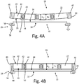
- FIGS. 4A-4B show damper 20 being attached to airfoil 10.
- FIG. 4A is a side cross-sectional view of damper 20 before it is attached to airfoil 10.
- FIG. 4B is a side cross-sectional view of damper 20 after it is attached to airfoil 10.
- Airfoil 10 includes first surface 16 and second surface 18.
- Damper 20 includes body 22, first surface 24, second surface 26, attachment mechanisms 28, frame 30, attachment nodes 40, damper nodes 42, ribs 44, cavities 48, and damping material 50.
- Attachment mechanisms 28 include clamp tabs 56 and bolts 58.
- rib height H 1 and damper node height H 2 are also shown in FIGS. 4A-4B .
- Airfoil 10 has first surface 16 and second surface 18. First surface 16 faces and abuts damper 20 and second surface 18 faces away from damper 20. Second surface 18 can be machined when damper 20 is attached to airfoil 10.
- Damper 20 includes body 22 that forms a main body portion of damper 20.
- Body 22 has first surface 24 that faces away from airfoil 10 and second surface 26 that faces and abuts first surface 16 of airfoil 10.
- Damper 20 also includes attachment mechanisms 28 that fasten to body 22 of damper 20 to attach damper 20 to airfoil 10.
- Frame 30 forms an outer periphery of body 22 of damper 20.
- Attachment nodes 40 and damper nodes 42 are positioned within frame 30.
- Ribs 44 extend from frame 30 to attachment nodes 40 and damper nodes 42 and between attachment nodes 40 and damper nodes 42.
- Attachment mechanisms 28 are attached to attachment nodes 40 to attach damper 20 to airfoil 10.
- Damper nodes 42 each have one of cavities 48 formed in it. Cavities 48 are filled with damping material 50. Damping material 50 can be a particle material or a liquid material.
- Ribs 44 have rib height H 1 .
- Damper nodes 42 have damper node height H 2 . As shown in FIGS. 4A-4B , damper node height H 2 is larger than rib height H 1 . Ribs 44 and damper nodes 42 are flush with one another on first surface 24 of damper 20, but damper nodes 42 extend past ribs 44 on second surface 26 of damper 20. Damper node height H 2 is larger than rib height H 1 to allow damper nodes 42 to extend past ribs 44 on second surface 26 of damper 20. When damper 20 is attached to airfoil 10, damper nodes 42 will abut airfoil 10. As damper nodes 42 dissipate vibrations from airfoil 10, this ensures good contact between damper nodes 42 and airfoil 10.
- damper 20 Before damper 20 is clamped to airfoil 10, it has a reverse curvature with respect to airfoil 10. As shown in FIG. 4B , when damper 20 is attached to airfoil 10, damper 20 is deformed so that it conforms to airfoil 10 and sits tightly against airfoil 10. The spring force created by conforming damper 20 to airfoil 10 ensures firm contact between damper nodes 42 of damper 20 and airfoil 10 when damper 20 is attached to airfoil 10.
- Damper 20 is attached to airfoil 10 using attachment mechanisms 28.
- Attachment mechanisms 28 can include mechanical, adhesive, magnetic, pneumatic, hydraulic, or any other suitable means for attaching damper 20 to airfoil 10.
- attachment mechanisms 28 include clamp tab 56 and bolt 58.
- Clamp tab 56 has a notch cut into it that fits against an edge of airfoil 10. The notch of clamp tab 56 sits in part against second surface 18 of airfoil 10. Clamp tab 56 also sits against one attachment node 40. Both clamp tab 56 and attachment node 40 have an aperture extending through them.
- Bolt 58 is placed in the aperture of clamp tab 56 and attachment node 40 and is used to connect clamp tab 56 to attachment node 40.
- attachment mechanisms 28 can be shifted between attachment nodes 40.
- a portion of attachment mechanisms 28 cover a portion of second surface 18 of airfoil 10.
- attachment mechanisms 28 can be moved between attachment nodes 40 to allow access to the previously covered sections of second surface 18 of airfoil 10.
- damper nodes 42 The larger height of damper nodes 42, the reverse curvature of damper body 22, and the design of attachment mechanisms 28 all work together to form a firm contact between damper nodes 42 and airfoil 10.
- the firm contact between damper nodes 42 and airfoil 10 ensures that vibrations in airfoil 10 caused by machining processes are transferred to and dissipated in damper nodes 42.
- FIG. 5 is a perspective view of machining apparatus 70 that is machining airfoil 10 to which damper 20 is attached.
- Airfoil 10 includes tip 12, root 14, first surface 16, and second surface 18.
- Damper 20 includes body 22 and attachment mechanisms 28.
- Machining apparatus 70 includes first clamp 72, second clamp 74, and cutting tool 76.
- Airfoil 10 has tip 12 at a first end and root 14 at a second end.
- First surface 16 extends from root 14 to tip 12 and faces and abuts damper 20.
- Second surface 18 extends from root 14 to tip 12 and faces away from damper 20. Second surface 18 can be machined when damper 20 is attached to airfoil 10.
- Damper 20 includes body 22 that abuts first surface 16 of airfoil 10. Attachment mechanisms 28 attach body 22 of damper 20 to airfoil 10 and hold damper 20 in place on airfoil 10.
- Machining apparatus 70 is a milling apparatus in the embodiment shown in FIG. 5 .
- machining apparatus 70 can be any suitable machining apparatus.
- Machining apparatus 70 includes first clamp 72 and second clamp 74 to support airfoil 10.
- First clamp 72 is attached to tip 12 of airfoil 10
- second clamp 74 is attached to root 14 of airfoil 10.
- machining apparatus 70 can include any support structure to support any workpiece.
- Machining apparatus 70 further includes cutting tool 76.
- Cutting tool 76 moves throughout machining apparatus 70 to machine airfoil 10.
- cutting tool 76 can move through machining apparatus 70 to machine any workpiece.
- damper 20 is attached to airfoil 10 to dissipate the vibrations in airfoil 10 caused by the movement of cutting tool 76 across second surface 18 of airfoil 10. Damper 20 dissipates the vibrations with the damping material 50 in damper nodes 42 (damping material 50 and damper nodes 42 not shown in FIG. 5 ).
- FIG. 6 is a flowchart showing a machining process that uses damper 20.
- FIG. 6 includes first step 80, second step 82, third step 84, fourth step 86, and fifth step 88.
- First step 80 includes positioning a workpiece in a machining apparatus.
- airfoil 10 is positioned in machining apparatus 70.
- Tip 12 of airfoil 10 is attached to first clamp 72 of machining apparatus 70 and root 14 of airfoil 10 is attached to second clamp 74 of machining apparatus 70.
- any workpiece can be positioned in any machining apparatus in any suitable manner.
- Second step 82 includes rough machining the workpiece.
- cutting tool 76 of machining apparatus 70 moves across airfoil 10 to rough machine airfoil 10.
- any cutting tool or machining tool can rough machine any workpiece.
- Rough machining includes a first round of machining to take the workpiece from a rough state to an intermediate state.
- Third step 84 includes attaching damper 20 to the workpiece.
- damper 20 is attached to airfoil 10.
- Damper 20 is attached to airfoil 10 using attachment mechanisms 28. Attachment mechanisms 28 attach to attachment nodes 44 of damper 20.
- damper 20 can be attached to any suitable workpiece in any suitable manner.
- Fourth step 86 includes finish machining the workpiece.
- cutting tool 76 of machining apparatus 70 moves across airfoil 10 to finish machine airfoil 10.
- any cutting tool or machining tool can finish machine any workpiece.
- Finish machining includes a second round of machining to take the workpiece from an intermediate state to a final state. Finish machining includes more controlled machining to achieve a specific surface finish on the workpiece. Finish machining can generate significant chattering in the workpiece.
- Fifth step 88 includes dampening the vibrations from the chattering of the workpiece with damper 20.
- damper 20 dampens the vibrations in airfoil 10.
- damper 20 can dampen vibrations in any workpiece.
- Damper 20 dampens vibrations from the chattering of the workpiece by dissipating the vibrations in damper nodes 42. The vibrations move from frame 30 of damper 20 along ribs 44 to damper nodes 42.
- Damper nodes 42 contain damping material 50 in cavities 48. The vibrations are dissipated by moving damping material 50 in cavities 48.
- Damping material 50 can be a particle damping material that dissipates the vibrations due to the collision of the particles against the walls of cavities 48.
- damping material 50 can be a liquid damping material that dissipates the vibrations by using the energy from the vibrations to move the liquid damping material.
- FIG. 7 is a perspective view of a first side of damper 100 attached to airfoil 10.
- Airfoil 10 includes tip 12, root 14, first surface 16, and second surface 18.
- Damper 100 includes first body portion 102 and second body portion 104. Both of first body portion 102 and second body portion 104 have first surface 106, second surface 108, frame 110, first side 112, second side 114, third side 116, fourth side 118, attachment nodes 120, damper nodes 122, ribs 124, openings 126, cavities 128, and damping material 130.
- Airfoil 10 has tip 12 at a first end and root 14 at a second end.
- First surface 16 of airfoil 10 extends from root 14 to tip 12.
- Second surface 18 of airfoil 10 is opposite of first surface 16 of airfoil 10 and extends from root 14 to tip 12.
- Damper 100 is attached to airfoil 10.
- Damper 100 includes first body portion 102 and second body portion 104.
- First body portion 102 and second body portion 104 can be made out of a polymer, metallic, or composite material.
- First body portion 102 and second body portion 104 mirror one another and have the same structure.
- First body portion 102 is shown in full in FIG. 7 and will be discussed in greater detail below. However, the discussion of first body portion 102 below also applies to second body portion 104.
- First body portion 102 includes first surface 106 and second surface 108.
- First surface 106 of damper 100 faces away from airfoil 10, and second surface 108 of damper 100 faces and abuts first surface 16 of airfoil 10.
- Frame 110 forms an outer periphery of first body portion 102 of damper 100.
- Frame 110 has first side 112, second side 114, third side 116, and fourth side 118.
- First side 112 and second side 114 are opposite one another and third side 116 and fourth side 118 are opposite one another.
- First side 112 and second side 114 extend in a spanwise direction along a portion of airfoil 10.
- Third side 116 and fourth side 118 extend from first side 112 to second side 114 across airfoil 10.
- Damper 100 further includes attachment nodes 120 and damper nodes 122 positioned within frame 110.
- Attachment nodes 120 are positioned along first side 112 and second side 114 of frame 110.
- Damper nodes 122 are positioned along third side 116 and fourth side 114 and within frame 110 in a grid pattern.
- Attachment nodes 120 and damper nodes 122 are connected to one another and to frame 110 with ribs 124.
- Ribs 124 extend between attachment nodes 120 and damper nodes 122.
- Ribs 124 are design to transfer loads to damper nodes 122.
- Attachment nodes 120 are positioned along first side 112 and second side 114 of frame 110. Attachment nodes 120 on first body portion 102 are aligned with and attached to attachment nodes 120 (not shown in FIG. 7 ) on second body portion 102 to attach damper 100 to airfoil 10.
- Damper nodes 122 each have one of cavities 128 formed in it. Cavities 128 can be of any suitable shape, size, and orientation. Cavities 128 are filled with damping material 130. Damping material 130 can be a particle material or a liquid material.
- Damper 100 is attached to airfoil 10 so that second surface 108 of first body portion 102 abuts first surface 16 of airfoil 10 and so that second surface 108 (not shown in FIG. 7 ) of second body portion 104 abuts second surface 18 of airfoil 10. This leaves half of first surface 16 of airfoil 10 and half of second surface 18 of airfoil 10 exposed so that they can be machined.
- Airfoil 10 with damper 100 can be placed in a machining apparatus and machined with any suitable machining process. As airfoil 10 is machined, vibrations caused by the machining will be transferred from airfoil 10 to damper 100. Vibrations in damper 100 will move from frame 110 and ribs 124 to damper nodes 122. Damping material 130 in damper nodes 122 dissipate the vibrations to reduce the chattering of airfoil 10 caused by the machining process.
- a damper includes a damper body that is configured to be attached to a workpiece during a machining process.
- a first side of the damper body is configured to abut a first side of the workpiece.
- the damper body includes a frame forming an outer periphery of the damper body, a plurality of damper nodes with a cavity in each damper node positioned in the frame, and a plurality of ribs extending between the frame and the damper nodes.
- a damping material is positioned in the cavity of each damper node.
- damper of the preceding paragraph can optionally include, additionally and/or alternatively, any one or more of the following features, configurations and/or additional components:
- the damping material includes a plurality of particles.
- the plurality of particles are selected from the group consisting of steel, lead, tungsten carbide, or combination thereof.
- Each of the plurality of particles have a diameter of between 0.030 inches (0.762 millimeters) and 0.125 inches (3.175 millimeters).
- the damping material is a high density liquid metal or a high density liquid slurry.
- the damper body is made out of a material selected from the group consisting of an abrasion resistant polymer, a polymer, a metallic, a composite, or combinations thereof.
- the ribs are configured to transfer loads to the damper nodes.
- the plurality of damper nodes have a larger height than the ribs.
- the damper includes an attachment mechanism that is configured to attach to attachment nodes on the damper body to attach the damper body to a workpiece.
- the attachment mechanism is selected from the group consisting of a clamp, a bolt, an adhesive, a magnet, a pneumatic attachment, a hydraulic attachment, or combinations thereof.
- the damper body extends along a first surface of a workpiece and is attached to a first edge and a second edge of the workpiece.
- the damper body includes a first body portion extending along a first surface of a workpiece and a second body portion extending along a second surface of the workpiece, wherein the first body portion and the second body portion are attached to one another.
- the damper body is curved.
- a machining system includes a machine having a first clamp, a second clamp, and a cutting tool.
- a workpiece is positioned in the machine.
- a first end of the workpiece is held in the first clamp of the machine and a second end of the workpiece is held in the second clamp of the machine.
- a damper is attached to the workpiece.
- the damper includes a damper body with a first surface that abuts against and conforms to the workpiece.
- the damper body has a frame forming an outer periphery of the damper body, a plurality of damper nodes with a cavity in each of the damper nodes, and a plurality of ribs extending from the frame to the damper nodes.
- a damping material is positioned in the cavity of each damper node.
- machining system of the preceding paragraph can optionally include, additionally and/or alternatively, any one or more of the following features, configurations and/or additional components:
- a method of machining a workpiece includes positioning a workpiece in a machine.
- the workpiece is rough machined.
- a damper is attached to the workpiece.
- the damper has a damper body with a first surface that abuts against and conforms to the workpiece.
- the damper body has a frame forming an outer periphery of the damper body, a plurality of damper nodes with a cavity in each of the damper nodes, and a plurality of ribs extending from the frame to the damper nodes.
- the workpiece is finish machined. Vibrations in the workpiece are dampened with a damping material in the damper nodes of the damper.
- the method of the preceding paragraph can optionally include, additionally and/or alternatively, any one or more of the following features, configurations and/or additional components:
- the damping material in the damper nodes is selected from the group consisting of particles of steel, particles of lead, particles of tungsten carbide, liquid mercury, or combinations thereof.
- Attaching a damper to the workpiece includes clamping the damper to the workpiece.
Landscapes
- Engineering & Computer Science (AREA)
- General Engineering & Computer Science (AREA)
- Mechanical Engineering (AREA)
- Auxiliary Devices For Machine Tools (AREA)
Abstract
Description
- The present invention relates to dampers, and in particular, to a damper for machining operations.
- Machining processes include a wide variety of manufacturing processes that are used to form a workpiece from raw material. An example of a machining process includes a milling process. Milling processes move a cutting tool across a workpiece to remove material from the workpiece.
- Workpieces that are thin and have a high aspect ratio can be subject to chattering during machining processes due to their inherent flexibility. Chattering is rapid vibrations caused by machining processes. In milling processes, specifically, the interrupted cutting action of the cutting tool causes the chattering in the workpiece. Chattering produces waviness on the machined surface, a poor surface finish, and profile errors in the workpiece. Chattering can also result in delamination of composite workpieces.
- Dampers can be used to dampen chattering during machining processes. Numerous damping solutions that exist face challenges. A first damping solution is to create a flexible damping sheet to support the workpiece, however flexible damping sheets are typically only effective over a narrow range of frequencies. This limits the speed at which the cutting tool can be turned and restricts the flutes on the cutting tool to avoid reaching frequencies outside of the range covered by the flexible damping sheet. A second damping solution is to use an elastomeric damper that can be attached to a workpiece, however the effectiveness of elastomeric dampers decreases as they age and can vary with temperature changes. A third damping solution is to fabricate complex fixtures to support and hold workpieces, however custom, complex fixtures can be expensive to produce. Further, once a complex fixture has been made, it can be time consuming and costly to adapt the fixture to accommodate design changes in the workpiece. A need exists for a simple workpiece damper that can dampen a broad spectrum of frequencies, is easy to install on and remove from a workpiece, has a low cost to manufacture, and can be easily adapted to accommodate design changes in the workpiece.
- A damper includes a damper body that is configured to be attached to a workpiece during a machining process. A first side of the damper body is configured to abut a first side of the workpiece. The damper body includes a frame forming an outer periphery of the damper body, a plurality of damper nodes with a cavity in each damper node positioned in the frame, and a plurality of ribs extending between the frame and the damper nodes. A damping material is positioned in the cavity of each damper node.
- A machining system includes a machine having a first clamp, a second clamp, and a cutting tool. A workpiece is positioned in the machine. A first end of the workpiece is held in the first clamp of the machine and a second end of the workpiece is held in the second clamp of the machine. A damper is attached to the workpiece. The damper includes a damper body with a first surface that abuts against and conforms to the workpiece. The damper body has a frame forming an outer periphery of the damper body, a plurality of damper nodes with a cavity in each of the damper nodes, and a plurality of ribs extending from the frame to the damper nodes. A damping material is positioned in the cavity of each damper node.
- A method of machining a workpiece includes positioning a workpiece in a machine. The workpiece is rough machined. A damper is attached to the workpiece. The damper has a damper body with a first surface that abuts against and conforms to the workpiece. The damper body has a frame forming an outer periphery of the damper body, a plurality of damper nodes with a cavity in each of the damper nodes, and a plurality of ribs extending from the frame to the damper nodes. The workpiece is finish machined. Vibrations in the workpiece are dampened with a damping material in the damper nodes of the damper.
-
-
FIG. 1A is a perspective view of a first side of a first embodiment of a damper attached to an airfoil. -
FIG. 1B is a perspective view of a second side of the first embodiment of the damper attached to the airfoil shown inFIG. 1A . -
FIG. 2A is a cross-sectional view of a cavity in a damper node of the first embodiment of the damper with a particle damping material. -
FIG. 2B is a cross-sectional view of the cavity in the damper node of the first embodiment of the damper with a liquid damping material. -
FIG. 3A is a cross-sectional view of the cavity in the damper node shown inFIG. 2A with an aperture. -
FIG. 3B is a cross-sectional view of the cavity in the damper node shown inFIG. 3A with a plug in the aperture. -
FIG. 4A is a side cross-sectional view of the first embodiment of the damper before it is attached to the airfoil. -
FIG. 4B is a side cross-sectional view of the first embodiment of the damper after it is attached to the airfoil. -
FIG. 5 is a perspective view of a machining apparatus that is machining the airfoil to which the first embodiment of the damper is attached. -
FIG. 6 is a flowchart showing a machining process that uses the first embodiment of the damper. -
FIG. 7 is a perspective view of a first side of a second embodiment of a damper attached to an airfoil. - Disclosed is a damper that can be attached to a workpiece during machining processes to dampen vibrations associated with the machining processes. The damper can be manufactured using an additive manufacturing process or a three-dimensional (3D) printing process, which allows the damper to be easily and quickly manufactured. Further, the damper can be designed to accommodate a particular workpiece and easily modified if the design of the workpiece is changed. The damper includes damper nodes that have cavities that are filled with a damping material to dampen vibrations from the machining process. The damping material in the damper can be a particle damping material or a liquid damping material. The type, size, shape, and volume of damping material that is used can be specifically selected to accommodate each particular workpiece.
-
FIGS. 1A- 1B show damper 20 attached toairfoil 10.FIG. 1A is a perspective view of a first side ofdamper 20 attached toairfoil 10.FIG. 1B is a perspective view of a second side ofdamper 20 attached toairfoil 10.Airfoil 10 includestip 12,root 14,first surface 16, andsecond surface 18.Damper 20 includesbody 22,first surface 24,second surface 26,attachment mechanisms 28,frame 30,first side 32,second side 34,third side 36,fourth side 38,attachment nodes 40,damper nodes 42,ribs 44,openings 46,cavities 48, and dampingmaterial 50. -
Airfoil 10 hastip 12 at a first end and root 14 at a second end.First surface 16 ofairfoil 10 extends fromroot 14 to tip 12.Second surface 18 ofairfoil 10 is opposite offirst surface 16 ofairfoil 10 and extends fromroot 14 to tip 12.Airfoil 10 is a workpiece that is to be machined in the embodiment shown inFIGS. 1A-1B .Airfoil 10 can be made out of aluminum and can be between 2 feet (60.96 centimeters) and 3 feet (91.44 centimeters) long. In alternate embodiments,airfoil 10 can be any workpiece that needs machining. For instance, the workpiece can be thin ribs, bulkheads, fluid tank walls, case walls, brackets, hollow struts, manifolds, or additively manufacturing grown reduced density lattice cores for structural beams and panels. -
Damper 20 is attached toairfoil 10.Damper 20 includesbody 22 that forms a main portion ofdamper 20.Body 22 includesfirst surface 24 andsecond surface 26.First surface 24 ofdamper 20 faces away fromairfoil 10, andsecond surface 26 ofdamper 20 faces and abutsfirst surface 16 ofairfoil 10.Body 22 ofdamper 20 can be made out of a polymer, metallic, or composite material. In a preferred embodiment,body 22 ofdamper 20 is made out of an abrasion resistant polymer, such as nylon or polyurethane. Further, the abrasion resistant polymer may be filled with a reinforcing material. -
Damper 20 further includesattachment mechanisms 28 that fasten tobody 22 ofdamper 20 to attachdamper 20 toairfoil 10.Attachment mechanisms 28 can include mechanical, adhesive, magnetic, pneumatic, hydraulic, or any other suitable means for attachingdamper 20 toairfoil 10. Preferably, quick release clamps, such as toggle clamps or swing arm clamps, are used.Attachment mechanisms 28 can be shifted alongairfoil 10 to allow machining of the entirety ofsecond surface 18 ofairfoil 10. -
Frame 30 forms an outer periphery ofbody 22 ofdamper 20.Frame 30 hasfirst side 32,second side 34,third side 36, andfourth side 38.First side 32 andsecond side 34 are opposite one another andthird side 36 andfourth side 38 are opposite one another.First side 32 andsecond side 34 extend alongairfoil 10 fromroot 14 to tip 12.Third side 36 extends fromfirst side 32 tosecond side 34 adjacent to tip 12.Fourth side 38 extends fromfirst side 32 tosecond side 34 adjacent to root 14. -
Damper 20 further includesattachment nodes 40 anddamper nodes 42 positioned withinframe 30.Attachment nodes 40 are positioned alongfirst side 32 andsecond side 34 offrame 30.Damper nodes 42 are positioned in a grid pattern inframe 30.Attachment nodes 40 anddamper nodes 42 are connected to one another and to frame 30 withribs 44.Ribs 44 extend fromfirst side 32,second side 34,third side 36, andfourth side 38 toattachment nodes 40 anddamper nodes 42 and betweenattachment nodes 40 anddamper nodes 42.Ribs 44 are designed to transfer loads todamper nodes 42. -
Attachment nodes 40 are positioned alongfirst side 32 andsecond side 34 offrame 30.Attachment mechanisms 28 are attached toattachment nodes 40 to attachdamper 20 toairfoil 10.Damper nodes 42 each have one ofcavities 48 formed in them.Cavities 48 can be of any suitable shape, size, and orientation. In a preferred embodiment,cavities 48 have approximately twice the thickness asairfoil 10.Cavities 48 are filled with dampingmaterial 50. Dampingmaterial 50 can be a particle damping material or a liquid damping material. -
Damper 20 is attached toairfoil 10 so thatfirst surface 16 ofairfoil 10 abutssecond surface 26 ofdamper 20. This leavessecond surface 18 ofairfoil 10 exposed so that it can be machined.Airfoil 10 withdamper 20 can be placed in a machining apparatus and machined with any suitable machining process. Asairfoil 10 is machined, vibrations caused by the machining will be transferred fromairfoil 10 todamper 20.Airfoil 10 is a very flexible workpiece and can be subject to significant vibrations during machining processes. Vibrations indamper 20 will move fromframe 30 andribs 44 todamper nodes 42. Dampingmaterial 50 indamper nodes 42 dissipates the vibrations to reduce the vibrations inairfoil 10 caused by the machining process. -
Damper 20 dissipates the vibrations inairfoil 10 during the machining process to better control the machining process. Having better control over the machining process means thatairfoil 10 will have an improved surface finish and a controlled profile. Whendamper 20 is attached toairfoil 10,airfoil 10 can be machined faster to reduce overall production costs associated with manufacturingairfoil 10. Further,damper 20 can be easily attached to and detached fromairfoil 10 usingattachment mechanisms 28. The ease of use ofattachment mechanisms 28 also allowsdamper 20 to be repositioned as needed onairfoil 10 during a machining process. -
Damper 20 can effectively dampen a wide range of frequencies by the selection of the material that formsdamper body 22, by selection of the number ofdamper nodes 42 included indamper 20, by selection of the size and shape ofcavities 48 indamper nodes 42, and the selection and volume of dampingmaterial 50 that is positioned incavities 48 ofdamper nodes 42. Being effective across a wide range of frequencies allowsdamper 20 to be used in a wide range of applications. -
Damper 20 can be custom designed to dampenairfoil 10 or any other workpiece.Damper 20 can be manufactured with an additive manufacturing process or a three-dimensional (3D) printing process, which allows asingle damper 20 or a plurality ofdampers 20 to be manufactured as needed. Further, additive manufacturing processes and three-dimensional (3D) printing processes only need short lead times in which to manufacture a part. A computer-aided drafting (CAD) model representing the design ofdamper 20 is used to manufacturedamper 20 when using additive manufacturing processes or three-dimensional (3D) printing processes. If modifications are made to the design ofairfoil 10, the computer-aided drafting (CAD) model ofdamper 20 can be likewise modified anddamper 20 can be quickly printed to accommodate the design changes ofairfoil 10. Further, using an additive manufacturing process or a three-dimensional (3D) printing process to manufacturedamper 20 is less costly than other manufacturing methods. -
FIGS. 2A- 2B show cavity 48 indamper node 42 ofdamper 20.FIG. 2A is a cross-sectional view ofcavity 48 indamper node 42 ofdamper 20 with particle damping material 50'.FIG. 2B is a cross-sectional view ofcavity 48 indamper node 42 ofdamper 20 withliquid damping material 50".Damper 20 includesdamper node 42,ribs 44, andcavity 48.FIG. 2A includes particle damping material 50'.FIG. 2B includes liquid dampingmaterial 50". - As shown in
FIGS. 1A-1B ,damper 20 includes a plurality ofdamper nodes 42 that are held indamper 20 withribs 44. Asingle damper node 42 is shown inFIGS. 2A-2B , however the following applies to everydamper node 42 indamper 20.Cavity 48 is formed indamper node 42.Cavity 48 is filled with a damping material. - In
FIG. 2A ,cavity 48 is filled with particle damping material 50'. Particle damping material 50' includes a plurality of particles of select size, shape, and density. Particle damping material 50' can be particles of steel, lead, tungsten carbide, or any other suitable material. The particle spheres of particle damping material 50' can preferably be between 0.030 inches (0.762 millimeters) and 0.125 inches (3.175 millimeters). - Damping takes place in
damper 20 shown inFIG. 2A primarily by momentum exchange in the collision between particle damping material 50' and the walls ofcavity 48. The energy from vibrations reachingdamper node 42 are dissipated when the particle spheres of particle damping material 50' collide against the walls ofcavity 48. Particle damping material 50' does not fill the entirety ofcavity 48 to allow the particle spheres room to move withincavity 48. The volume ofcavity 48 that is filled can vary depending on specific applications. To dampen low frequencies, approximately 15% to 20% ofcavity 48 can be left open. To dampen high frequencies, approximately 5% or less ofcavity 48 can be left open. - Inelastic collisions between the particles of particle damping material 50', friction, and heat conversion also contribute to damping taking place in
damper 20 with particle damping material 50'. Particle damping material 50' allowsdamper 20 to act as a Particle Impact Damper (PID). The size, shape, and density of the particles in the PID and the amount of the particles in the PID can be specifically selected based on the given application, making the PID effective for use in many applications. PIDs also perform well under a wide range of temperatures and frequencies and have a long life. - In
FIG. 2B ,cavity 48 is filled with liquid dampingmaterial 50". Liquid dampingmaterial 50" can be a high density liquid metal, a high density liquid slurry, or any other suitable liquid. An example of a high density liquid metal that can be used includes liquid mercury. Liquid mercury provides good damping due to its high density. The energy from vibrations that reachdamper node 42 are dissipated as the energy is used to move liquid dampingmaterial 50". Liquid dampingmaterial 50" does not fillcavity 48 to allow room forliquid damping material 50" to move withincavity 48. Theliquid damping material 50" is free to move in any direction incavity 48, allowing it to dissipate any vibrations that reachdamper node 42. - Particle damping material 50' and liquid damping
material 50" can both be used indamper 20 to dampen vibrations from machining processes. Both particle damping material 50' and liquid dampingmaterial 50" can be custom picked to suit different applications. This allowsdamper 20 to be custom designed to be highly effective in each application. -
FIGS. 3A- 3B show cavity 48 indamper node 42 ofdamper 20.FIG. 3A is a cross-sectional view ofcavity 48 indamper node 42 withaperture 52.FIG. 3B is a cross-sectional view ofcavity 48 indamper node 42 withplug 54 inaperture 52.Damper 20 includesdamper node 42,ribs 44,cavity 48, dampingmaterial 50,aperture 52, and plug 54. - As shown in
FIGS. 1A-1B ,damper 20 includes a plurality ofdamper nodes 42 that are held indamper 20 withribs 44. Asingle damper node 42 is shown inFIGS. 3A-3B , however the following applies to everydamper node 42 indamper 20.Cavity 48 is formed indamper node 42.Cavity 48 is filled with dampingmaterial 50.Aperture 52 is formed indamper node 42 to provide access tocavity 48, as shown inFIG. 3A .Plug 54 is placed inaperture 52 to sealcavity 48, as shown inFIG. 3B . -
Damper 20 can be manufactured with any suitable manufacturing process, including additive manufacturing or a three-dimensional (3D) printing process.Aperture 52 can be formed indamper node 42 whendamper 20 is manufactured.Damper 20 can also be manufactured and thenaperture 52 can be formed indamper node 42 afterdamper 20 has been manufactured.Aperture 52 provides access tocavity 48 indamper node 42. If material is left incavity 48 ofdamper node 42 afterdamper 20 is manufactured,aperture 52 allows the material to be removed fromcavity 48. For instance, ifdamper 20 is manufactured with an additive manufacturing process there will be loose powder incavity 48 ofdamper node 42. The loose powder incavity 48 ofdamper node 42 can be removed throughaperture 52. - After any material left in
cavity 48 from manufacturing is removed fromcavity 48 throughaperture 52, dampingmaterial 50 can be placed incavity 48 throughaperture 52. The dampingmaterial 50 can be a particle damping material or a liquid damping material. After dampingmaterial 50 has been placed incavity 48 ofdamper node 42, plug 54 can be positioned inaperture 52 to sealcavity 48.Plug 54 can connect toaperture 52 in a number of ways.Aperture 52 and plug 54 are show with threads inFIGS. 3A-3B , allowingplug 54 to be screwed into place inaperture 52. In alternate embodiments, plug 54 can be bonded, heat sealed, or otherwise sealed intoaperture 52. -
Aperture 52 and plug 54 allowdamper 20 to be manufactured without dampingmaterial 50 needing to be placed incavity 48 during the manufacturing. This allowsdamper 20 to be later filled with dampingmaterial 50 and then tested. If it is found that more or less or a different dampingmaterial 50 would provide better damping results, plug 54 can be removed fromaperture 52 ofdamper 20 to provide access tocavity 48. After dampingmaterial 50 has been modified, plug 54 can be resealed inaperture 52. This allows great flexibility in the design ofdamper 20, asdamper 20 can be modified based on the results of testing without having to redesign the entirety ofdamper 20. This ensures thatdamper 20 has high damping ability for each specific application. -
FIGS. 4A- 4B show damper 20 being attached toairfoil 10.FIG. 4A is a side cross-sectional view ofdamper 20 before it is attached toairfoil 10.FIG. 4B is a side cross-sectional view ofdamper 20 after it is attached toairfoil 10.Airfoil 10 includesfirst surface 16 andsecond surface 18.Damper 20 includesbody 22,first surface 24,second surface 26,attachment mechanisms 28,frame 30,attachment nodes 40,damper nodes 42,ribs 44,cavities 48, and dampingmaterial 50.Attachment mechanisms 28 includeclamp tabs 56 andbolts 58. Also shown inFIGS. 4A-4B are rib height H1 and damper node height H2. -
Airfoil 10 hasfirst surface 16 andsecond surface 18.First surface 16 faces and abutsdamper 20 andsecond surface 18 faces away fromdamper 20.Second surface 18 can be machined whendamper 20 is attached toairfoil 10. -
Damper 20 includesbody 22 that forms a main body portion ofdamper 20.Body 22 hasfirst surface 24 that faces away fromairfoil 10 andsecond surface 26 that faces and abutsfirst surface 16 ofairfoil 10.Damper 20 also includesattachment mechanisms 28 that fasten tobody 22 ofdamper 20 to attachdamper 20 toairfoil 10. -
Frame 30 forms an outer periphery ofbody 22 ofdamper 20.Attachment nodes 40 anddamper nodes 42 are positioned withinframe 30.Ribs 44 extend fromframe 30 toattachment nodes 40 anddamper nodes 42 and betweenattachment nodes 40 anddamper nodes 42.Attachment mechanisms 28 are attached toattachment nodes 40 to attachdamper 20 toairfoil 10.Damper nodes 42 each have one ofcavities 48 formed in it.Cavities 48 are filled with dampingmaterial 50. Dampingmaterial 50 can be a particle material or a liquid material. -
Ribs 44 have rib height H1. Damper nodes 42 have damper node height H2. As shown inFIGS. 4A-4B , damper node height H2 is larger than rib height H1. Ribs 44 anddamper nodes 42 are flush with one another onfirst surface 24 ofdamper 20, butdamper nodes 42 extendpast ribs 44 onsecond surface 26 ofdamper 20. Damper node height H2 is larger than rib height H1 to allowdamper nodes 42 to extendpast ribs 44 onsecond surface 26 ofdamper 20. Whendamper 20 is attached toairfoil 10,damper nodes 42 will abutairfoil 10. Asdamper nodes 42 dissipate vibrations fromairfoil 10, this ensures good contact betweendamper nodes 42 andairfoil 10. - As shown in
FIG. 4A , beforedamper 20 is clamped toairfoil 10, it has a reverse curvature with respect toairfoil 10. As shown inFIG. 4B , whendamper 20 is attached toairfoil 10,damper 20 is deformed so that it conforms to airfoil 10 and sits tightly againstairfoil 10. The spring force created by conformingdamper 20 toairfoil 10 ensures firm contact betweendamper nodes 42 ofdamper 20 andairfoil 10 whendamper 20 is attached toairfoil 10. -
Damper 20 is attached toairfoil 10 usingattachment mechanisms 28.Attachment mechanisms 28 can include mechanical, adhesive, magnetic, pneumatic, hydraulic, or any other suitable means for attachingdamper 20 toairfoil 10. In the embodiment shown inFIGS. 4A-4B ,attachment mechanisms 28 includeclamp tab 56 andbolt 58.Clamp tab 56 has a notch cut into it that fits against an edge ofairfoil 10. The notch ofclamp tab 56 sits in part againstsecond surface 18 ofairfoil 10.Clamp tab 56 also sits against oneattachment node 40. Bothclamp tab 56 andattachment node 40 have an aperture extending through them.Bolt 58 is placed in the aperture ofclamp tab 56 andattachment node 40 and is used to connectclamp tab 56 toattachment node 40. - Not every
attachment node 40 needs to be attached to oneattachment mechanism 28 to attachdamper 20 toairfoil 10. Rather,attachment mechanisms 28 can be shifted betweenattachment nodes 40. Whenattachment mechanisms 28 are attached toattachment nodes 40, a portion ofattachment mechanisms 28 cover a portion ofsecond surface 18 ofairfoil 10. To allow access to an entirety ofsecond surface 18 for machining,attachment mechanisms 28 can be moved betweenattachment nodes 40 to allow access to the previously covered sections ofsecond surface 18 ofairfoil 10. - The larger height of
damper nodes 42, the reverse curvature ofdamper body 22, and the design ofattachment mechanisms 28 all work together to form a firm contact betweendamper nodes 42 andairfoil 10. The firm contact betweendamper nodes 42 andairfoil 10 ensures that vibrations inairfoil 10 caused by machining processes are transferred to and dissipated indamper nodes 42. -
FIG. 5 is a perspective view ofmachining apparatus 70 that is machiningairfoil 10 to whichdamper 20 is attached.Airfoil 10 includestip 12,root 14,first surface 16, andsecond surface 18.Damper 20 includesbody 22 andattachment mechanisms 28.Machining apparatus 70 includesfirst clamp 72,second clamp 74, and cuttingtool 76. -
Airfoil 10 hastip 12 at a first end and root 14 at a second end.First surface 16 extends fromroot 14 to tip 12 and faces and abutsdamper 20.Second surface 18 extends fromroot 14 to tip 12 and faces away fromdamper 20.Second surface 18 can be machined whendamper 20 is attached toairfoil 10.Damper 20 includesbody 22 that abutsfirst surface 16 ofairfoil 10.Attachment mechanisms 28 attachbody 22 ofdamper 20 toairfoil 10 and holddamper 20 in place onairfoil 10. -
Machining apparatus 70 is a milling apparatus in the embodiment shown inFIG. 5 . In alternate embodiments,machining apparatus 70 can be any suitable machining apparatus.Machining apparatus 70 includesfirst clamp 72 andsecond clamp 74 to supportairfoil 10.First clamp 72 is attached to tip 12 ofairfoil 10, andsecond clamp 74 is attached to root 14 ofairfoil 10. In alternate embodiments,machining apparatus 70 can include any support structure to support any workpiece.Machining apparatus 70 further includes cuttingtool 76. Cuttingtool 76 moves throughoutmachining apparatus 70 tomachine airfoil 10. In alternate embodiments, cuttingtool 76 can move throughmachining apparatus 70 to machine any workpiece. - As cutting
tool 76 moves acrosssecond surface 18 ofairfoil 10,airfoil 10 will be subject to chattering. Chattering is rapid vibrations caused by machining processes.Damper 20 is attached toairfoil 10 to dissipate the vibrations inairfoil 10 caused by the movement of cuttingtool 76 acrosssecond surface 18 ofairfoil 10.Damper 20 dissipates the vibrations with the dampingmaterial 50 in damper nodes 42 (dampingmaterial 50 anddamper nodes 42 not shown inFIG. 5 ). -
FIG. 6 is a flowchart showing a machining process that usesdamper 20.FIG. 6 includesfirst step 80,second step 82,third step 84,fourth step 86, andfifth step 88. -
First step 80 includes positioning a workpiece in a machining apparatus. In the embodiment discussed above inFIGS. 1A-5 ,airfoil 10 is positioned inmachining apparatus 70.Tip 12 ofairfoil 10 is attached tofirst clamp 72 ofmachining apparatus 70 androot 14 ofairfoil 10 is attached tosecond clamp 74 ofmachining apparatus 70. In alternate embodiments, any workpiece can be positioned in any machining apparatus in any suitable manner. -
Second step 82 includes rough machining the workpiece. In the embodiment discussed above inFIGS. 1A-5 , cuttingtool 76 ofmachining apparatus 70 moves acrossairfoil 10 torough machine airfoil 10. In alternate embodiments, any cutting tool or machining tool can rough machine any workpiece. Rough machining includes a first round of machining to take the workpiece from a rough state to an intermediate state. -
Third step 84 includes attachingdamper 20 to the workpiece. In the embodiment discussed above inFIGS. 1A-5 ,damper 20 is attached toairfoil 10.Damper 20 is attached toairfoil 10 usingattachment mechanisms 28.Attachment mechanisms 28 attach toattachment nodes 44 ofdamper 20. In alternate embodiments,damper 20 can be attached to any suitable workpiece in any suitable manner. -
Fourth step 86 includes finish machining the workpiece. In the embodiment discussed above inFIGS. 1A-5 , cuttingtool 76 ofmachining apparatus 70 moves acrossairfoil 10 to finishmachine airfoil 10. In alternate embodiments, any cutting tool or machining tool can finish machine any workpiece. Finish machining includes a second round of machining to take the workpiece from an intermediate state to a final state. Finish machining includes more controlled machining to achieve a specific surface finish on the workpiece. Finish machining can generate significant chattering in the workpiece. -
Fifth step 88 includes dampening the vibrations from the chattering of the workpiece withdamper 20. In the embodiment discussed above inFIGS. 1A-5 ,damper 20 dampens the vibrations inairfoil 10. In alternate embodiments,damper 20 can dampen vibrations in any workpiece.Damper 20 dampens vibrations from the chattering of the workpiece by dissipating the vibrations indamper nodes 42. The vibrations move fromframe 30 ofdamper 20 alongribs 44 todamper nodes 42.Damper nodes 42 contain dampingmaterial 50 incavities 48. The vibrations are dissipated by moving dampingmaterial 50 incavities 48. Dampingmaterial 50 can be a particle damping material that dissipates the vibrations due to the collision of the particles against the walls ofcavities 48. Alternatively, dampingmaterial 50 can be a liquid damping material that dissipates the vibrations by using the energy from the vibrations to move the liquid damping material. -
FIG. 7 is a perspective view of a first side ofdamper 100 attached toairfoil 10.Airfoil 10 includestip 12,root 14,first surface 16, andsecond surface 18.Damper 100 includesfirst body portion 102 andsecond body portion 104. Both offirst body portion 102 andsecond body portion 104 havefirst surface 106,second surface 108,frame 110,first side 112,second side 114,third side 116,fourth side 118,attachment nodes 120,damper nodes 122,ribs 124,openings 126,cavities 128, and dampingmaterial 130. -
Airfoil 10 hastip 12 at a first end and root 14 at a second end.First surface 16 ofairfoil 10 extends fromroot 14 to tip 12.Second surface 18 ofairfoil 10 is opposite offirst surface 16 ofairfoil 10 and extends fromroot 14 to tip 12. -
Damper 100 is attached toairfoil 10.Damper 100 includesfirst body portion 102 andsecond body portion 104.First body portion 102 andsecond body portion 104 can be made out of a polymer, metallic, or composite material.First body portion 102 andsecond body portion 104 mirror one another and have the same structure.First body portion 102 is shown in full inFIG. 7 and will be discussed in greater detail below. However, the discussion offirst body portion 102 below also applies tosecond body portion 104. -
First body portion 102 includesfirst surface 106 andsecond surface 108.First surface 106 ofdamper 100 faces away fromairfoil 10, andsecond surface 108 ofdamper 100 faces and abutsfirst surface 16 ofairfoil 10. -
Frame 110 forms an outer periphery offirst body portion 102 ofdamper 100.Frame 110 hasfirst side 112,second side 114,third side 116, andfourth side 118.First side 112 andsecond side 114 are opposite one another andthird side 116 andfourth side 118 are opposite one another.First side 112 andsecond side 114 extend in a spanwise direction along a portion ofairfoil 10.Third side 116 andfourth side 118 extend fromfirst side 112 tosecond side 114 acrossairfoil 10. -
Damper 100 further includesattachment nodes 120 anddamper nodes 122 positioned withinframe 110.Attachment nodes 120 are positioned alongfirst side 112 andsecond side 114 offrame 110.Damper nodes 122 are positioned alongthird side 116 andfourth side 114 and withinframe 110 in a grid pattern.Attachment nodes 120 anddamper nodes 122 are connected to one another and to frame 110 withribs 124.Ribs 124 extend betweenattachment nodes 120 anddamper nodes 122.Ribs 124 are design to transfer loads todamper nodes 122. -
Attachment nodes 120 are positioned alongfirst side 112 andsecond side 114 offrame 110.Attachment nodes 120 onfirst body portion 102 are aligned with and attached to attachment nodes 120 (not shown inFIG. 7 ) onsecond body portion 102 to attachdamper 100 toairfoil 10.Damper nodes 122 each have one ofcavities 128 formed in it.Cavities 128 can be of any suitable shape, size, and orientation.Cavities 128 are filled with dampingmaterial 130. Dampingmaterial 130 can be a particle material or a liquid material. -
Damper 100 is attached toairfoil 10 so thatsecond surface 108 offirst body portion 102 abutsfirst surface 16 ofairfoil 10 and so that second surface 108 (not shown inFIG. 7 ) ofsecond body portion 104 abutssecond surface 18 ofairfoil 10. This leaves half offirst surface 16 ofairfoil 10 and half ofsecond surface 18 ofairfoil 10 exposed so that they can be machined.Airfoil 10 withdamper 100 can be placed in a machining apparatus and machined with any suitable machining process. Asairfoil 10 is machined, vibrations caused by the machining will be transferred fromairfoil 10 todamper 100. Vibrations indamper 100 will move fromframe 110 andribs 124 todamper nodes 122. Dampingmaterial 130 indamper nodes 122 dissipate the vibrations to reduce the chattering ofairfoil 10 caused by the machining process. - The following are non-exclusive descriptions of possible embodiments of the present invention.
- A damper includes a damper body that is configured to be attached to a workpiece during a machining process. A first side of the damper body is configured to abut a first side of the workpiece. The damper body includes a frame forming an outer periphery of the damper body, a plurality of damper nodes with a cavity in each damper node positioned in the frame, and a plurality of ribs extending between the frame and the damper nodes. A damping material is positioned in the cavity of each damper node.
- The damper of the preceding paragraph can optionally include, additionally and/or alternatively, any one or more of the following features, configurations and/or additional components:
- The damper is manufactured using an additive manufacturing process or a three-dimensional printing process.
- The damping material includes a plurality of particles.
- The plurality of particles are selected from the group consisting of steel, lead, tungsten carbide, or combination thereof.
- Each of the plurality of particles have a diameter of between 0.030 inches (0.762 millimeters) and 0.125 inches (3.175 millimeters).
- The damping material is a high density liquid metal or a high density liquid slurry.
- The damper body is made out of a material selected from the group consisting of an abrasion resistant polymer, a polymer, a metallic, a composite, or combinations thereof.
- The ribs are configured to transfer loads to the damper nodes.
- The plurality of damper nodes have a larger height than the ribs.
- The damper includes an attachment mechanism that is configured to attach to attachment nodes on the damper body to attach the damper body to a workpiece.
- The attachment mechanism is selected from the group consisting of a clamp, a bolt, an adhesive, a magnet, a pneumatic attachment, a hydraulic attachment, or combinations thereof.
- The damper body extends along a first surface of a workpiece and is attached to a first edge and a second edge of the workpiece.
- The damper body includes a first body portion extending along a first surface of a workpiece and a second body portion extending along a second surface of the workpiece, wherein the first body portion and the second body portion are attached to one another.
- The damper body is curved.
- A machining system includes a machine having a first clamp, a second clamp, and a cutting tool. A workpiece is positioned in the machine. A first end of the workpiece is held in the first clamp of the machine and a second end of the workpiece is held in the second clamp of the machine. A damper is attached to the workpiece. The damper includes a damper body with a first surface that abuts against and conforms to the workpiece. The damper body has a frame forming an outer periphery of the damper body, a plurality of damper nodes with a cavity in each of the damper nodes, and a plurality of ribs extending from the frame to the damper nodes. A damping material is positioned in the cavity of each damper node.
- The machining system of the preceding paragraph can optionally include, additionally and/or alternatively, any one or more of the following features, configurations and/or additional components:
- The damper body is twice as thick as the workpiece.
- A method of machining a workpiece includes positioning a workpiece in a machine. The workpiece is rough machined. A damper is attached to the workpiece. The damper has a damper body with a first surface that abuts against and conforms to the workpiece. The damper body has a frame forming an outer periphery of the damper body, a plurality of damper nodes with a cavity in each of the damper nodes, and a plurality of ribs extending from the frame to the damper nodes. The workpiece is finish machined. Vibrations in the workpiece are dampened with a damping material in the damper nodes of the damper.
- The method of the preceding paragraph can optionally include, additionally and/or alternatively, any one or more of the following features, configurations and/or additional components:
- Positioning a workpiece in a machine includes clamping a first end of the workpiece in a first clamp in the machine, and clamping a second end of the workpiece in a second clamp in the machine.
- The damping material in the damper nodes is selected from the group consisting of particles of steel, particles of lead, particles of tungsten carbide, liquid mercury, or combinations thereof.
- Attaching a damper to the workpiece includes clamping the damper to the workpiece.
- While the invention has been described with reference to an exemplary embodiment(s), it will be understood by those skilled in the art that various changes may be made and equivalents may be substituted for elements thereof without departing from the scope of the invention. In addition, many modifications may be made to adapt a particular situation or material to the teachings of the invention without departing from the essential scope thereof. Therefore, it is intended that the invention not be limited to the particular embodiment(s) disclosed, but that the invention will include all embodiments falling within the scope of the appended claims.
Claims (15)
- A damper (20; 100) comprising:a damper body (22) that is configured to be attached to a workpiece (10) during a machining process, wherein a first side (26; 108) of the damper body (22) is configured to abut a first side (16; 18) of the workpiece (10), and the damper body (22) further comprises:a frame (30; 110) forming an outer periphery of the damper body (22);a plurality of damper nodes (42; 122) with a cavity (48; 128) in each damper node (42; 122) positioned in the frame (30; 110); anda plurality of ribs (44; 124) extending between the frame (30; 110) and the damper nodes (42; 122); anda damping material (50; 50'; 50"; 130) positioned in the cavity (48; 128) of each damper node (42; 122).
- The damper of claim 1, wherein the damper (20; 100) is manufactured using an additive manufacturing process or a three-dimensional printing process.
- The damper of claim 1 or 2, wherein the damping material (50; 50') includes a plurality of particles, optionally selected from the group consisting of steel, lead, tungsten carbide, or combination thereof.
- The damper of claim 3, wherein each of the plurality of particles have a diameter of between 0.030 inches (0.762 millimeters) and 0.125 inches (3.175 millimeters).
- The damper of claim 1 or 2, wherein the damping material (50") is a high density liquid metal or a high density liquid slurry.
- The damper of any preceding claim, wherein the damper body (22) is made out of an abrasion resistant polymer, a polymer, a metallic, a composite, or combinations thereof.
- The damper of any preceding claim, wherein the plurality of damper nodes (42; 122) have a larger height (H2) than the ribs (44; 124).
- The damper of any preceding claim, further comprising an attachment mechanism (28) that is configured to attach to attachment nodes (40; 120) on the damper body (22) to attach the damper body (22) to the workpiece (10), optionally wherein the attachment mechanism (28) is a clamp (56), a bolt (58), an adhesive, a magnet, a pneumatic attachment, a hydraulic attachment, or combinations thereof.
- The damper of any preceding claim, wherein the damper body (22) is configured to extend along a first surface (16) of the workpiece (10) and to be attached to a first edge and a second edge of the workpiece (10).
- The damper of any of claims 1 to 8, wherein the damper body includes a first body portion (102) configured to extend along a first surface (16) of the workpiece (10) and a second body portion (104) configured to extend along a second surface (18) of the workpiece (10), wherein the first body portion (102) and the second body portion (104) are attached to one another.
- The damper of any preceding claim, wherein the damper body (22) is curved.
- A machining system comprising:a machine (70) having a first clamp (72), a second clamp (74), and a cutting tool (76);a workpiece (10) positioned in the machine (70), wherein a first end (12) of the workpiece (10) is held in the first clamp (72) of the machine (70) and a second end (14) of the workpiece (10) is held in the second clamp (74) of the machine (70); andthe damper (20; 100) of any preceding claim attached to the workpiece (10).
- A method of machining a workpiece (10) comprises:positioning a workpiece (10) in a machine (70);rough machining the workpiece (10);attaching a damper (20; 100) to the workpiece (10), wherein the damper (20; 100) has a damper body (22) with a first surface (26; 108) that abuts against and conforms to the workpiece (10), wherein the damper body (22) has a frame (30; 110) forming an outer periphery of the damper body (22), a plurality of damper nodes (42; 122) with a cavity (48; 128) in each of the damper nodes (42; 122), and a plurality of ribs (44; 124) extending from the frame (30; 120) to the damper nodes (42; 122);finish machining the workpiece (10); anddamping vibrations in the workpiece (10) with a damping material (50; 50'; 50"; 130) in the damper nodes (42; 122) of the damper (20; 100).
- The method of claim 13, wherein positioning a workpiece (10) in a machine (70) further comprises clamping a first end (12) of the workpiece (10) in a first clamp (72) in the machine (70); and
clamping a second end (14) of the workpiece (10) in a second clamp (74) in the machine (70). - The method of claim 13 or 14, wherein the damping material (50; 50'; 50"; 130) in the damper nodes (42; 122) comprises particles of steel, particles of lead, particles of tungsten carbide, liquid mercury, or combinations thereof.
Applications Claiming Priority (1)
| Application Number | Priority Date | Filing Date | Title |
|---|---|---|---|
| US15/341,596 US10330167B2 (en) | 2016-11-02 | 2016-11-02 | Damper for machining processes |
Publications (2)
| Publication Number | Publication Date |
|---|---|
| EP3321029A1 true EP3321029A1 (en) | 2018-05-16 |
| EP3321029B1 EP3321029B1 (en) | 2019-10-16 |
Family
ID=60244949
Family Applications (1)
| Application Number | Title | Priority Date | Filing Date |
|---|---|---|---|
| EP17199768.7A Active EP3321029B1 (en) | 2016-11-02 | 2017-11-02 | Damper for machining processes |
Country Status (2)
| Country | Link |
|---|---|
| US (1) | US10330167B2 (en) |
| EP (1) | EP3321029B1 (en) |
Cited By (2)
| Publication number | Priority date | Publication date | Assignee | Title |
|---|---|---|---|---|
| CN109352362A (en) * | 2018-11-30 | 2019-02-19 | 上海航天精密机械研究所 | Five pawl connector exterior arc surface integration turning machining devices |
| CN117703911A (en) * | 2023-05-31 | 2024-03-15 | 荣耀终端有限公司 | Hinge assembly and electronic equipment |
Families Citing this family (8)
| Publication number | Priority date | Publication date | Assignee | Title |
|---|---|---|---|---|
| CN108746782B (en) * | 2018-05-29 | 2020-06-16 | 成都飞机工业(集团)有限责任公司 | Milling method of high-precision suspended web |
| CN108994639B (en) * | 2018-07-27 | 2020-09-11 | 成都飞机工业(集团)有限责任公司 | Low-stress clamping method for boss lap joint part |
| US20200108551A1 (en) * | 2018-10-08 | 2020-04-09 | Rolls-Royce North American Technologies, Inc. | Damped articles and systems and techniques for forming damped articles |
| CN112212775B (en) * | 2020-09-28 | 2022-03-22 | 中国航发贵州黎阳航空动力有限公司 | Cambered surface thin-wall part detection and deformation prevention device and use method |
| EP3995253A1 (en) * | 2020-11-04 | 2022-05-11 | GF Machining Solutions AG | A device for stabilizing a workpiece in a machine tool |
| CN113695946B (en) * | 2021-09-13 | 2023-05-23 | 黑龙江农业经济职业学院 | Positioning fixture for machining automobile plate |
| TWI834509B (en) * | 2023-03-02 | 2024-03-01 | 國立中央大學 | Cutting apparatus and its holding device |
| CN118254021B (en) * | 2024-05-29 | 2024-09-10 | 成都飞机工业(集团)有限责任公司 | Flutter suppression device for machining thin-wall parts of airplane and process system thereof |
Citations (5)
| Publication number | Priority date | Publication date | Assignee | Title |
|---|---|---|---|---|
| US4323145A (en) * | 1976-11-03 | 1982-04-06 | Allen Clayton H | Vibration damping method and means having non-contacting sound damping means |
| FR2519276A1 (en) * | 1982-01-05 | 1983-07-08 | Lajoye Pierre | Mounting for thin walled cylinder during machining of bore - uses rebated end plates to centre work in rigid tube with inflatable rings in annular gap |
| US20020070584A1 (en) * | 1998-02-04 | 2002-06-13 | Oakwood Energy Management, Inc. | Formed energy absorber |
| DE10330528A1 (en) * | 2003-07-05 | 2005-02-17 | Arthur Prib | Clamping device assembled of at least two clamping elements, comprising springs embedded in shock absorbing material |
| EP3050670A1 (en) * | 2015-01-29 | 2016-08-03 | Rolls-Royce plc | Apparatus for damping machining vibration of an object |
Family Cites Families (14)
| Publication number | Priority date | Publication date | Assignee | Title |
|---|---|---|---|---|
| US2776101A (en) * | 1955-08-10 | 1957-01-01 | Mcdermott Francis Roland | Method of and means for mounting a machine on a vibration absorbing pad |
| US3690414A (en) | 1970-11-04 | 1972-09-12 | Cincinnati Milacron Inc | Vibration absorber for a supported member |
| US4803112A (en) * | 1986-04-24 | 1989-02-07 | Hayakawa Rubber Co., Ltd. | Impact-cushioning sheets and direct-applying restraint type floor damping structures using the same |
| NL9000294A (en) * | 1990-02-07 | 1991-09-02 | Willy Van Goubergen | VIBRATION DAMPER. |
| US5538373A (en) | 1992-02-20 | 1996-07-23 | Giddings & Lewis, Inc. | Machine tool vibration isolation system |
| US5706249A (en) * | 1996-04-01 | 1998-01-06 | Cushman; William B. | Panel spacer with acoustic and vibration damping |
| US5765818A (en) * | 1996-07-17 | 1998-06-16 | Sabatino; David B. | Vibration damping structure for use with a machine tool |
| US6382603B1 (en) * | 2001-02-08 | 2002-05-07 | Lockheed Martin Corporation | Ridged elastomer mount |
| NO321556B1 (en) | 2002-04-30 | 2006-05-29 | Teeness As | Damping device for damping vibrations |
| US7125211B2 (en) | 2003-10-17 | 2006-10-24 | Racer Machinery International Inc. | Apparatus and method for damping vibration in a machine tool |
| US20100122880A1 (en) * | 2008-11-17 | 2010-05-20 | Gm Global Technology Operations, Inc. | Surface configurations for damping inserts |
| US8770567B2 (en) * | 2009-10-06 | 2014-07-08 | Quickmill Inc. | Cushioned support platform |
| DE102012108098A1 (en) * | 2012-08-31 | 2014-03-06 | Sandvik Intellectual Property Ab | Vibration-damped tool |
| PL2926941T3 (en) * | 2014-04-03 | 2017-08-31 | Bystronic Laser Ag | Jet or beam processing device |
-
2016
- 2016-11-02 US US15/341,596 patent/US10330167B2/en active Active
-
2017
- 2017-11-02 EP EP17199768.7A patent/EP3321029B1/en active Active
Patent Citations (5)
| Publication number | Priority date | Publication date | Assignee | Title |
|---|---|---|---|---|
| US4323145A (en) * | 1976-11-03 | 1982-04-06 | Allen Clayton H | Vibration damping method and means having non-contacting sound damping means |
| FR2519276A1 (en) * | 1982-01-05 | 1983-07-08 | Lajoye Pierre | Mounting for thin walled cylinder during machining of bore - uses rebated end plates to centre work in rigid tube with inflatable rings in annular gap |
| US20020070584A1 (en) * | 1998-02-04 | 2002-06-13 | Oakwood Energy Management, Inc. | Formed energy absorber |
| DE10330528A1 (en) * | 2003-07-05 | 2005-02-17 | Arthur Prib | Clamping device assembled of at least two clamping elements, comprising springs embedded in shock absorbing material |
| EP3050670A1 (en) * | 2015-01-29 | 2016-08-03 | Rolls-Royce plc | Apparatus for damping machining vibration of an object |
Cited By (2)
| Publication number | Priority date | Publication date | Assignee | Title |
|---|---|---|---|---|
| CN109352362A (en) * | 2018-11-30 | 2019-02-19 | 上海航天精密机械研究所 | Five pawl connector exterior arc surface integration turning machining devices |
| CN117703911A (en) * | 2023-05-31 | 2024-03-15 | 荣耀终端有限公司 | Hinge assembly and electronic equipment |
Also Published As
| Publication number | Publication date |
|---|---|
| EP3321029B1 (en) | 2019-10-16 |
| US10330167B2 (en) | 2019-06-25 |
| US20180119766A1 (en) | 2018-05-03 |
Similar Documents
| Publication | Publication Date | Title |
|---|---|---|
| EP3321029B1 (en) | Damper for machining processes | |
| CN103228405B (en) | machine tool | |
| Pachbhai et al. | A review on design of fixtures | |
| CN104028759B (en) | For manufacturing lamination manufacture method and the three dimensional object of three dimensional object | |
| Song et al. | Boring bar with constrained layer damper for improving process stability | |
| CN104417761B (en) | System and method for forming perforation in cylinder section | |
| US10695838B2 (en) | Tool body, a tool and a method for manufacturing a tool body | |
| US10464138B2 (en) | Tool holder and manufacturing method thereof | |
| US8398342B2 (en) | Workpiece vibration reduction | |
| EP3428395A1 (en) | Gas turbine engine fan blade, design, and fabrication | |
| Biju et al. | Investigation into effect of particle impact damping (PID) on surface topography in boring operation | |
| EP2841225A1 (en) | Method for manufacturing a fluid routing component by layer-wise buildup | |
| Dong et al. | Stability of lateral vibration in robotic rotary ultrasonic drilling | |
| Liu et al. | Analysis of the vibration characteristics and adjustment method of boring bar with a variable stiffness vibration absorber | |
| US8430610B2 (en) | Fluttering prevention device for working machine | |
| BR102017009287B1 (en) | TOOL MACHINE WITH AN ACTIVE DAMPING SYSTEM | |
| JP2020059063A5 (en) | ||
| CN102294611A (en) | The Fixture for Machining the Inclined Surface of the Connecting Rod's Small End | |
| KR102112994B1 (en) | Vibration reduction processing method and device using synchronous control of robot | |
| Lee et al. | Novel applications of composite structures to robots, machine tools and automobiles | |
| CN108846242A (en) | Chatter suppression method for milling of thin-walled parts based on pre-tensioning stress | |
| Izamshah et al. | Cutter path strategies for shoulder milling of thin deflecting walls | |
| JP7237698B2 (en) | Cutting tools | |
| CN206153598U (en) | Damping tools | |
| CN115106562A (en) | Method for shaping a tool holder or a tool base and tool holder or tool base |
Legal Events
| Date | Code | Title | Description |
|---|---|---|---|
| PUAI | Public reference made under article 153(3) epc to a published international application that has entered the european phase |
Free format text: ORIGINAL CODE: 0009012 |
|
| STAA | Information on the status of an ep patent application or granted ep patent |
Free format text: STATUS: THE APPLICATION HAS BEEN PUBLISHED |
|
| AK | Designated contracting states |
Kind code of ref document: A1 Designated state(s): AL AT BE BG CH CY CZ DE DK EE ES FI FR GB GR HR HU IE IS IT LI LT LU LV MC MK MT NL NO PL PT RO RS SE SI SK SM TR |
|
| AX | Request for extension of the european patent |
Extension state: BA ME |
|
| STAA | Information on the status of an ep patent application or granted ep patent |
Free format text: STATUS: REQUEST FOR EXAMINATION WAS MADE |
|
| 17P | Request for examination filed |
Effective date: 20181115 |
|
| RBV | Designated contracting states (corrected) |
Designated state(s): AL AT BE BG CH CY CZ DE DK EE ES FI FR GB GR HR HU IE IS IT LI LT LU LV MC MK MT NL NO PL PT RO RS SE SI SK SM TR |
|
| GRAP | Despatch of communication of intention to grant a patent |
Free format text: ORIGINAL CODE: EPIDOSNIGR1 |
|
| STAA | Information on the status of an ep patent application or granted ep patent |
Free format text: STATUS: GRANT OF PATENT IS INTENDED |
|
| INTG | Intention to grant announced |
Effective date: 20190426 |
|
| GRAS | Grant fee paid |
Free format text: ORIGINAL CODE: EPIDOSNIGR3 |
|
| GRAA | (expected) grant |
Free format text: ORIGINAL CODE: 0009210 |
|
| STAA | Information on the status of an ep patent application or granted ep patent |
Free format text: STATUS: THE PATENT HAS BEEN GRANTED |
|
| AK | Designated contracting states |
Kind code of ref document: B1 Designated state(s): AL AT BE BG CH CY CZ DE DK EE ES FI FR GB GR HR HU IE IS IT LI LT LU LV MC MK MT NL NO PL PT RO RS SE SI SK SM TR |
|
| REG | Reference to a national code |
Ref country code: GB Ref legal event code: FG4D |
|
| REG | Reference to a national code |
Ref country code: CH Ref legal event code: EP |
|
| REG | Reference to a national code |
Ref country code: DE Ref legal event code: R096 Ref document number: 602017007838 Country of ref document: DE |
|
| REG | Reference to a national code |
Ref country code: IE Ref legal event code: FG4D |
|
| REG | Reference to a national code |
Ref country code: AT Ref legal event code: REF Ref document number: 1190818 Country of ref document: AT Kind code of ref document: T Effective date: 20191115 |
|
| REG | Reference to a national code |
Ref country code: NL Ref legal event code: MP Effective date: 20191016 |
|
| REG | Reference to a national code |
Ref country code: LT Ref legal event code: MG4D |
|
| REG | Reference to a national code |
Ref country code: AT Ref legal event code: MK05 Ref document number: 1190818 Country of ref document: AT Kind code of ref document: T Effective date: 20191016 |
|
| PG25 | Lapsed in a contracting state [announced via postgrant information from national office to epo] |
Ref country code: SE Free format text: LAPSE BECAUSE OF FAILURE TO SUBMIT A TRANSLATION OF THE DESCRIPTION OR TO PAY THE FEE WITHIN THE PRESCRIBED TIME-LIMIT Effective date: 20191016 Ref country code: LV Free format text: LAPSE BECAUSE OF FAILURE TO SUBMIT A TRANSLATION OF THE DESCRIPTION OR TO PAY THE FEE WITHIN THE PRESCRIBED TIME-LIMIT Effective date: 20191016 Ref country code: NL Free format text: LAPSE BECAUSE OF FAILURE TO SUBMIT A TRANSLATION OF THE DESCRIPTION OR TO PAY THE FEE WITHIN THE PRESCRIBED TIME-LIMIT Effective date: 20191016 Ref country code: LT Free format text: LAPSE BECAUSE OF FAILURE TO SUBMIT A TRANSLATION OF THE DESCRIPTION OR TO PAY THE FEE WITHIN THE PRESCRIBED TIME-LIMIT Effective date: 20191016 Ref country code: PL Free format text: LAPSE BECAUSE OF FAILURE TO SUBMIT A TRANSLATION OF THE DESCRIPTION OR TO PAY THE FEE WITHIN THE PRESCRIBED TIME-LIMIT Effective date: 20191016 Ref country code: GR Free format text: LAPSE BECAUSE OF FAILURE TO SUBMIT A TRANSLATION OF THE DESCRIPTION OR TO PAY THE FEE WITHIN THE PRESCRIBED TIME-LIMIT Effective date: 20200117 Ref country code: NO Free format text: LAPSE BECAUSE OF FAILURE TO SUBMIT A TRANSLATION OF THE DESCRIPTION OR TO PAY THE FEE WITHIN THE PRESCRIBED TIME-LIMIT Effective date: 20200116 Ref country code: PT Free format text: LAPSE BECAUSE OF FAILURE TO SUBMIT A TRANSLATION OF THE DESCRIPTION OR TO PAY THE FEE WITHIN THE PRESCRIBED TIME-LIMIT Effective date: 20200217 Ref country code: FI Free format text: LAPSE BECAUSE OF FAILURE TO SUBMIT A TRANSLATION OF THE DESCRIPTION OR TO PAY THE FEE WITHIN THE PRESCRIBED TIME-LIMIT Effective date: 20191016 Ref country code: BG Free format text: LAPSE BECAUSE OF FAILURE TO SUBMIT A TRANSLATION OF THE DESCRIPTION OR TO PAY THE FEE WITHIN THE PRESCRIBED TIME-LIMIT Effective date: 20200116 Ref country code: AT Free format text: LAPSE BECAUSE OF FAILURE TO SUBMIT A TRANSLATION OF THE DESCRIPTION OR TO PAY THE FEE WITHIN THE PRESCRIBED TIME-LIMIT Effective date: 20191016 |
|
| PG25 | Lapsed in a contracting state [announced via postgrant information from national office to epo] |
Ref country code: RS Free format text: LAPSE BECAUSE OF FAILURE TO SUBMIT A TRANSLATION OF THE DESCRIPTION OR TO PAY THE FEE WITHIN THE PRESCRIBED TIME-LIMIT Effective date: 20191016 Ref country code: HR Free format text: LAPSE BECAUSE OF FAILURE TO SUBMIT A TRANSLATION OF THE DESCRIPTION OR TO PAY THE FEE WITHIN THE PRESCRIBED TIME-LIMIT Effective date: 20191016 Ref country code: IS Free format text: LAPSE BECAUSE OF FAILURE TO SUBMIT A TRANSLATION OF THE DESCRIPTION OR TO PAY THE FEE WITHIN THE PRESCRIBED TIME-LIMIT Effective date: 20200224 |
|
| PG25 | Lapsed in a contracting state [announced via postgrant information from national office to epo] |
Ref country code: AL Free format text: LAPSE BECAUSE OF FAILURE TO SUBMIT A TRANSLATION OF THE DESCRIPTION OR TO PAY THE FEE WITHIN THE PRESCRIBED TIME-LIMIT Effective date: 20191016 |
|
| REG | Reference to a national code |
Ref country code: DE Ref legal event code: R097 Ref document number: 602017007838 Country of ref document: DE |
|
| PG2D | Information on lapse in contracting state deleted |
Ref country code: IS |
|
| PG25 | Lapsed in a contracting state [announced via postgrant information from national office to epo] |
Ref country code: RO Free format text: LAPSE BECAUSE OF FAILURE TO SUBMIT A TRANSLATION OF THE DESCRIPTION OR TO PAY THE FEE WITHIN THE PRESCRIBED TIME-LIMIT Effective date: 20191016 Ref country code: CZ Free format text: LAPSE BECAUSE OF FAILURE TO SUBMIT A TRANSLATION OF THE DESCRIPTION OR TO PAY THE FEE WITHIN THE PRESCRIBED TIME-LIMIT Effective date: 20191016 Ref country code: EE Free format text: LAPSE BECAUSE OF FAILURE TO SUBMIT A TRANSLATION OF THE DESCRIPTION OR TO PAY THE FEE WITHIN THE PRESCRIBED TIME-LIMIT Effective date: 20191016 Ref country code: LU Free format text: LAPSE BECAUSE OF NON-PAYMENT OF DUE FEES Effective date: 20191102 Ref country code: DK Free format text: LAPSE BECAUSE OF FAILURE TO SUBMIT A TRANSLATION OF THE DESCRIPTION OR TO PAY THE FEE WITHIN THE PRESCRIBED TIME-LIMIT Effective date: 20191016 Ref country code: MC Free format text: LAPSE BECAUSE OF FAILURE TO SUBMIT A TRANSLATION OF THE DESCRIPTION OR TO PAY THE FEE WITHIN THE PRESCRIBED TIME-LIMIT Effective date: 20191016 Ref country code: ES Free format text: LAPSE BECAUSE OF FAILURE TO SUBMIT A TRANSLATION OF THE DESCRIPTION OR TO PAY THE FEE WITHIN THE PRESCRIBED TIME-LIMIT Effective date: 20191016 Ref country code: IS Free format text: LAPSE BECAUSE OF FAILURE TO SUBMIT A TRANSLATION OF THE DESCRIPTION OR TO PAY THE FEE WITHIN THE PRESCRIBED TIME-LIMIT Effective date: 20200216 |
|
| PLBE | No opposition filed within time limit |
Free format text: ORIGINAL CODE: 0009261 |
|
| REG | Reference to a national code |
Ref country code: BE Ref legal event code: MM Effective date: 20191130 |
|
| STAA | Information on the status of an ep patent application or granted ep patent |
Free format text: STATUS: NO OPPOSITION FILED WITHIN TIME LIMIT |
|
| PG25 | Lapsed in a contracting state [announced via postgrant information from national office to epo] |
Ref country code: SK Free format text: LAPSE BECAUSE OF FAILURE TO SUBMIT A TRANSLATION OF THE DESCRIPTION OR TO PAY THE FEE WITHIN THE PRESCRIBED TIME-LIMIT Effective date: 20191016 Ref country code: SM Free format text: LAPSE BECAUSE OF FAILURE TO SUBMIT A TRANSLATION OF THE DESCRIPTION OR TO PAY THE FEE WITHIN THE PRESCRIBED TIME-LIMIT Effective date: 20191016 Ref country code: IT Free format text: LAPSE BECAUSE OF FAILURE TO SUBMIT A TRANSLATION OF THE DESCRIPTION OR TO PAY THE FEE WITHIN THE PRESCRIBED TIME-LIMIT Effective date: 20191016 |
|
| 26N | No opposition filed |
Effective date: 20200717 |
|
| PG25 | Lapsed in a contracting state [announced via postgrant information from national office to epo] |
Ref country code: IE Free format text: LAPSE BECAUSE OF NON-PAYMENT OF DUE FEES Effective date: 20191102 |
|
| PG25 | Lapsed in a contracting state [announced via postgrant information from national office to epo] |
Ref country code: BE Free format text: LAPSE BECAUSE OF NON-PAYMENT OF DUE FEES Effective date: 20191130 Ref country code: SI Free format text: LAPSE BECAUSE OF FAILURE TO SUBMIT A TRANSLATION OF THE DESCRIPTION OR TO PAY THE FEE WITHIN THE PRESCRIBED TIME-LIMIT Effective date: 20191016 |
|
| PG25 | Lapsed in a contracting state [announced via postgrant information from national office to epo] |
Ref country code: CY Free format text: LAPSE BECAUSE OF FAILURE TO SUBMIT A TRANSLATION OF THE DESCRIPTION OR TO PAY THE FEE WITHIN THE PRESCRIBED TIME-LIMIT Effective date: 20191016 |
|
| PG25 | Lapsed in a contracting state [announced via postgrant information from national office to epo] |
Ref country code: LI Free format text: LAPSE BECAUSE OF FAILURE TO SUBMIT A TRANSLATION OF THE DESCRIPTION OR TO PAY THE FEE WITHIN THE PRESCRIBED TIME-LIMIT Effective date: 20201130 Ref country code: CH Free format text: LAPSE BECAUSE OF FAILURE TO SUBMIT A TRANSLATION OF THE DESCRIPTION OR TO PAY THE FEE WITHIN THE PRESCRIBED TIME-LIMIT Effective date: 20201130 |
|
| REG | Reference to a national code |
Ref country code: CH Ref legal event code: PL |
|
| PG25 | Lapsed in a contracting state [announced via postgrant information from national office to epo] |
Ref country code: MT Free format text: LAPSE BECAUSE OF FAILURE TO SUBMIT A TRANSLATION OF THE DESCRIPTION OR TO PAY THE FEE WITHIN THE PRESCRIBED TIME-LIMIT Effective date: 20191016 Ref country code: HU Free format text: LAPSE BECAUSE OF FAILURE TO SUBMIT A TRANSLATION OF THE DESCRIPTION OR TO PAY THE FEE WITHIN THE PRESCRIBED TIME-LIMIT; INVALID AB INITIO Effective date: 20171102 |
|
| PG25 | Lapsed in a contracting state [announced via postgrant information from national office to epo] |
Ref country code: TR Free format text: LAPSE BECAUSE OF FAILURE TO SUBMIT A TRANSLATION OF THE DESCRIPTION OR TO PAY THE FEE WITHIN THE PRESCRIBED TIME-LIMIT Effective date: 20191016 |
|
| PG25 | Lapsed in a contracting state [announced via postgrant information from national office to epo] |
Ref country code: MK Free format text: LAPSE BECAUSE OF FAILURE TO SUBMIT A TRANSLATION OF THE DESCRIPTION OR TO PAY THE FEE WITHIN THE PRESCRIBED TIME-LIMIT Effective date: 20191016 |
|
| REG | Reference to a national code |
Ref country code: DE Ref legal event code: R081 Ref document number: 602017007838 Country of ref document: DE Owner name: RAYTHEON TECHNOLOGIES CORPORATION (N.D.GES.D.S, US Free format text: FORMER OWNER: UNITED TECHNOLOGIES CORPORATION, FARMINGTON, CONN., US Ref country code: DE Ref legal event code: R081 Ref document number: 602017007838 Country of ref document: DE Owner name: RTX CORPORATION (N.D.GES.D. STAATES DELAWARE),, US Free format text: FORMER OWNER: UNITED TECHNOLOGIES CORPORATION, FARMINGTON, CONN., US |
|
| P01 | Opt-out of the competence of the unified patent court (upc) registered |
Effective date: 20230520 |
|
| REG | Reference to a national code |
Ref country code: DE Ref legal event code: R081 Ref document number: 602017007838 Country of ref document: DE Owner name: RTX CORPORATION (N.D.GES.D. STAATES DELAWARE),, US Free format text: FORMER OWNER: RAYTHEON TECHNOLOGIES CORPORATION (N.D.GES.D.STAATES DELAWARE), ARLINGTON, VA, US |
|
| PGFP | Annual fee paid to national office [announced via postgrant information from national office to epo] |
Ref country code: DE Payment date: 20251022 Year of fee payment: 9 |
|
| PGFP | Annual fee paid to national office [announced via postgrant information from national office to epo] |
Ref country code: GB Payment date: 20251023 Year of fee payment: 9 |
|
| PGFP | Annual fee paid to national office [announced via postgrant information from national office to epo] |
Ref country code: FR Payment date: 20251022 Year of fee payment: 9 |