EP3320979A1 - Dispenser - Google Patents
Dispenser Download PDFInfo
- Publication number
- EP3320979A1 EP3320979A1 EP17205262.3A EP17205262A EP3320979A1 EP 3320979 A1 EP3320979 A1 EP 3320979A1 EP 17205262 A EP17205262 A EP 17205262A EP 3320979 A1 EP3320979 A1 EP 3320979A1
- Authority
- EP
- European Patent Office
- Prior art keywords
- container
- dispenser
- filter
- pressure
- liquid
- Prior art date
- Legal status (The legal status is an assumption and is not a legal conclusion. Google has not performed a legal analysis and makes no representation as to the accuracy of the status listed.)
- Granted
Links
Images


Classifications
-
- B—PERFORMING OPERATIONS; TRANSPORTING
- B05—SPRAYING OR ATOMISING IN GENERAL; APPLYING FLUENT MATERIALS TO SURFACES, IN GENERAL
- B05B—SPRAYING APPARATUS; ATOMISING APPARATUS; NOZZLES
- B05B11/00—Single-unit hand-held apparatus in which flow of contents is produced by the muscular force of the operator at the moment of use
- B05B11/0005—Components or details
- B05B11/0037—Containers
- B05B11/0039—Containers associated with means for compensating the pressure difference between the ambient pressure and the pressure inside the container, e.g. pressure relief means
- B05B11/0044—Containers associated with means for compensating the pressure difference between the ambient pressure and the pressure inside the container, e.g. pressure relief means compensating underpressure by ingress of atmospheric air into the container, i.e. with venting means
-
- B—PERFORMING OPERATIONS; TRANSPORTING
- B05—SPRAYING OR ATOMISING IN GENERAL; APPLYING FLUENT MATERIALS TO SURFACES, IN GENERAL
- B05B—SPRAYING APPARATUS; ATOMISING APPARATUS; NOZZLES
- B05B11/00—Single-unit hand-held apparatus in which flow of contents is produced by the muscular force of the operator at the moment of use
- B05B11/0005—Components or details
- B05B11/0037—Containers
-
- B—PERFORMING OPERATIONS; TRANSPORTING
- B05—SPRAYING OR ATOMISING IN GENERAL; APPLYING FLUENT MATERIALS TO SURFACES, IN GENERAL
- B05B—SPRAYING APPARATUS; ATOMISING APPARATUS; NOZZLES
- B05B11/00—Single-unit hand-held apparatus in which flow of contents is produced by the muscular force of the operator at the moment of use
- B05B11/0005—Components or details
- B05B11/0037—Containers
- B05B11/0039—Containers associated with means for compensating the pressure difference between the ambient pressure and the pressure inside the container, e.g. pressure relief means
-
- B—PERFORMING OPERATIONS; TRANSPORTING
- B05—SPRAYING OR ATOMISING IN GENERAL; APPLYING FLUENT MATERIALS TO SURFACES, IN GENERAL
- B05B—SPRAYING APPARATUS; ATOMISING APPARATUS; NOZZLES
- B05B11/00—Single-unit hand-held apparatus in which flow of contents is produced by the muscular force of the operator at the moment of use
- B05B11/0005—Components or details
- B05B11/0037—Containers
- B05B11/0039—Containers associated with means for compensating the pressure difference between the ambient pressure and the pressure inside the container, e.g. pressure relief means
- B05B11/0044—Containers associated with means for compensating the pressure difference between the ambient pressure and the pressure inside the container, e.g. pressure relief means compensating underpressure by ingress of atmospheric air into the container, i.e. with venting means
- B05B11/00442—Containers associated with means for compensating the pressure difference between the ambient pressure and the pressure inside the container, e.g. pressure relief means compensating underpressure by ingress of atmospheric air into the container, i.e. with venting means the means being actuated by the difference between the atmospheric pressure and the pressure inside the container
-
- B—PERFORMING OPERATIONS; TRANSPORTING
- B05—SPRAYING OR ATOMISING IN GENERAL; APPLYING FLUENT MATERIALS TO SURFACES, IN GENERAL
- B05B—SPRAYING APPARATUS; ATOMISING APPARATUS; NOZZLES
- B05B11/00—Single-unit hand-held apparatus in which flow of contents is produced by the muscular force of the operator at the moment of use
- B05B11/01—Single-unit hand-held apparatus in which flow of contents is produced by the muscular force of the operator at the moment of use characterised by the means producing the flow
- B05B11/02—Membranes or pistons acting on the contents inside the container, e.g. follower pistons
- B05B11/026—Membranes separating the content remaining in the container from the atmospheric air to compensate underpressure inside the container
-
- B—PERFORMING OPERATIONS; TRANSPORTING
- B05—SPRAYING OR ATOMISING IN GENERAL; APPLYING FLUENT MATERIALS TO SURFACES, IN GENERAL
- B05B—SPRAYING APPARATUS; ATOMISING APPARATUS; NOZZLES
- B05B11/00—Single-unit hand-held apparatus in which flow of contents is produced by the muscular force of the operator at the moment of use
- B05B11/01—Single-unit hand-held apparatus in which flow of contents is produced by the muscular force of the operator at the moment of use characterised by the means producing the flow
- B05B11/10—Pump arrangements for transferring the contents from the container to a pump chamber by a sucking effect and forcing the contents out through the dispensing nozzle
- B05B11/1042—Components or details
-
- B—PERFORMING OPERATIONS; TRANSPORTING
- B05—SPRAYING OR ATOMISING IN GENERAL; APPLYING FLUENT MATERIALS TO SURFACES, IN GENERAL
- B05B—SPRAYING APPARATUS; ATOMISING APPARATUS; NOZZLES
- B05B11/00—Single-unit hand-held apparatus in which flow of contents is produced by the muscular force of the operator at the moment of use
- B05B11/01—Single-unit hand-held apparatus in which flow of contents is produced by the muscular force of the operator at the moment of use characterised by the means producing the flow
- B05B11/10—Pump arrangements for transferring the contents from the container to a pump chamber by a sucking effect and forcing the contents out through the dispensing nozzle
- B05B11/1042—Components or details
- B05B11/1052—Actuation means
-
- A—HUMAN NECESSITIES
- A61—MEDICAL OR VETERINARY SCIENCE; HYGIENE
- A61L—METHODS OR APPARATUS FOR STERILISING MATERIALS OR OBJECTS IN GENERAL; DISINFECTION, STERILISATION OR DEODORISATION OF AIR; CHEMICAL ASPECTS OF BANDAGES, DRESSINGS, ABSORBENT PADS OR SURGICAL ARTICLES; MATERIALS FOR BANDAGES, DRESSINGS, ABSORBENT PADS OR SURGICAL ARTICLES
- A61L2/00—Disinfection or sterilisation of materials or objects, in general; Accessories therefor
- A61L2/02—Disinfection or sterilisation of materials or objects, in general; Accessories therefor using physical processes
- A61L2/08—Radiation
- A61L2/081—Gamma radiation
-
- A—HUMAN NECESSITIES
- A61—MEDICAL OR VETERINARY SCIENCE; HYGIENE
- A61L—METHODS OR APPARATUS FOR STERILISING MATERIALS OR OBJECTS IN GENERAL; DISINFECTION, STERILISATION OR DEODORISATION OF AIR; CHEMICAL ASPECTS OF BANDAGES, DRESSINGS, ABSORBENT PADS OR SURGICAL ARTICLES; MATERIALS FOR BANDAGES, DRESSINGS, ABSORBENT PADS OR SURGICAL ARTICLES
- A61L2103/00—Materials or objects being the target of disinfection or sterilisation
- A61L2103/23—Containers other than laboratory or medical, e.g. bottles or mail
-
- B—PERFORMING OPERATIONS; TRANSPORTING
- B05—SPRAYING OR ATOMISING IN GENERAL; APPLYING FLUENT MATERIALS TO SURFACES, IN GENERAL
- B05B—SPRAYING APPARATUS; ATOMISING APPARATUS; NOZZLES
- B05B11/00—Single-unit hand-held apparatus in which flow of contents is produced by the muscular force of the operator at the moment of use
- B05B11/01—Single-unit hand-held apparatus in which flow of contents is produced by the muscular force of the operator at the moment of use characterised by the means producing the flow
- B05B11/10—Pump arrangements for transferring the contents from the container to a pump chamber by a sucking effect and forcing the contents out through the dispensing nozzle
- B05B11/1001—Piston pumps
- B05B11/1009—Piston pumps actuated by a lever
- B05B11/1011—Piston pumps actuated by a lever without substantial movement of the nozzle in the direction of the pressure stroke
Definitions
- the present invention relates to a spray dispenser, particularly (but not exclusively) for use in dispensing sterile fluids.
- GB2391862 discloses a dispenser which is effective for dispensing sterile liquids.
- the dispenser comprises a collapsible inner vessel from which liquid is dispensed using a trigger-actuated pumping arrangement and a dip tube which extends to the bottom of the inner vessel, the inner vessel being located in a rigid outer bottle.
- the vessel collapses because no ingress of air is permitted into the vessel through the dispensing arrangement. Air is permitted to enter the space between the inner vessel and outer bottle.
- Such dispensers may be sterilised by filling the dispenser with fluid, sealing the dispenser in an air-tight bag (and optionally sealing this air-tight bag within a second and optionally a third air tight bag) and then irradiating the dispenser to sterilise the dispenser and its contents.
- irradiation may cause unwanted side effects.
- irradiation causes unwanted generation of gas in the container.
- Such generation of gas may cause unwanted bulging of the container due to a pressure build-up in the container and the container being made of sub-standard materials.
- the bottom of the outer container may bulge outwards, producing a bottle with a rounded bottom which cannot stand.
- leakage may be observed from one of several potentially weak points; unwanted leakage may be observed through the dispensing valve.
- the present invention seeks to mitigate one or more of the problems mentioned above and/or to provide an improved spray dispenser.
- a spray dispenser comprising a container for holding a liquid to be dispensed and a dispensing assembly for extracting liquid from said container, the dispensing assembly comprising a pressure-relief valve for release of excessive pressure in the container and a filter arranged to permit egress of gas from the container through the filter and through the pressure-relief valve, the filter inhibiting egress of liquid from the container through the filter.
- the spray dispenser of the present invention provides a dispenser particularly suitable for the dispensing of sterile liquids because it permits release of excessive pressure (such as may occur when the liquid contained in the container is irradiated to sterilise the container and its contents), the valve closing when said pressure has been relieved, thus inhibiting ingress of contaminants into the container. Furthermore, the filter inhibits egress of liquid from the container, therefore decreasing the likelihood of any spillage in the event that an overpressure occurs in the container. It is preferred that the pressure-relief valve is closed in the absence of excessive pressure to inhibit ingress of air and contaminants into the container. This is of particular benefit if it is undesirable to allow air into the container, for example, if the container comprises a collapsible liquid-containing portion.
- Filters which are typically used in the spray dispenser of the present invention also typically inhibit ingress of contaminants into the container through the pressure relief valve.
- the pressure-relief valve is not a dispensing valve (i.e. a valve through which liquid is, in use, dispensed).
- the spray dispenser of the present invention will typically be provided with a dispensing valve in addition to the pressure-relief valve.
- the filter typically prevents passage therethrough of liquid at the pressures which typically build-up within a container. These pressures are discussed below.
- the filter may be permeable to gas and impermeable to liquids.
- the filter will be impermeable to the liquid held within a container at the pressures generated when such filled containers are subjected to sterilising irradiation.
- Typical pressures are those generated when 1 litre of isopropyl alcohol contained within a container designed to contain 1 litre of liquid is subjected to 25 kGy of gamma radiation emitted by a cobalt source.
- the headspace above 1 litre of liquid is estimated to be approximately 20-30 ml.
- liquid is not an essential (but rather an optional) part of the spray dispenser of the present invention.
- the filter is in a gas flow path between the interior of the container and the pressure-relief valve.
- the pressure-relief valve may be in a gas flow path between the interior of the container and the filter.
- the filter preferably inhibits ingress of particulate into the container.
- the filter may comprise pores which permit passage therethrough of vapour, but inhibit passage therethrough of particulate. It is preferred that the filter inhibits passage therethrough of particles having a mean dimension of greater than 50 microns, more preferably greater than 5 microns and further more preferably 0.5 microns.
- the pores may have a mean greatest dimension of less than 10 microns, preferably less than 5 microns, more preferably less than 1 micron and further more preferably less than 0.3 microns.
- the filter may be substantially free of pores.
- the filter may comprise a membrane.
- the membrane may be hydrophobic, and may comprise a hydrophobic material such as polytetrafluoroethylene. Alternatively, the membrane may be oleophobic.
- the filter may be located within a filter housing.
- the container may comprise a fluid containment portion which may be collapsible (for example, the container may comprise a collapsible bag, typically made from plastics material).
- the container may comprise a container seal-forming surface.
- the spray dispenser may comprise a sealing member for forming a seal against the container seal-forming surface to inhibit ingress of air into the container.
- the sealing member may be provided as part of the dispensing assembly.
- the container may be sufficiently rigid that it does not collapse when liquid is extracted therefrom.
- the sealing member may be annular.
- the container seal-forming surface may be provided by a collar. If the container comprises a collapsible fluid containment portion, it is preferred that the collar is more rigid than the fluid containment portion.
- the pressure-relief valve may comprise any suitable one-way valve.
- the pressure-relief valve may comprise a spring valve, a diaphragm valve, a butterfly valve, a swing valve, a ball check valve or a duckbill valve.
- the duckbill valve is preferred because it may show good performance.
- the operation of the pressure-relief valve should preferably not be adversely affected by gamma radiation, such as is typically used to sterilise the contents of a container.
- the characteristics of the pressure-relief valve may be selected so that, after releasing excess pressure within the container, the valve closes appropriately to inhibit ingress of air into the container. This is particularly preferred, for example, if the container is collapsible.
- a container is typically subjected to a 25 kGy sterilising dose.
- the pressure-relief valve comprises a duckbill valve
- the duckbill valve should be made from a material whose performance is not affected by the sterilisation process to the extent that the duckbill valve does not function appropriately.
- duckbill valves may be made from elastomers whose properties are not significantly affected by irradiation. Details of such elastomers will be readily apparent to those skilled in the art. For example, details of such elastomers may be found in " The effects of sterilization methods on plastics and elastomers: the definitive user's guide and databook", edited by L. K. Massey, published by William Andrew, 2004 .
- the spray dispenser may be provided with a closure means, such as a cap, for inhibiting access to the container.
- a closure means such as a cap
- One or both of the pressure-relief valve and filter may be associated with the closure means.
- the dispensing assembly may comprise the closure means.
- the closure means may be provided with both the pressure-relief valve and the filter.
- the spray dispenser preferably comprises a housing for enclosing the container.
- the housing may support the container; this is particularly preferred if the container comprises a collapsible fluid containing portion.
- the closure means if present, may be removably attachable to the housing. This is particularly preferable if the closure means is provided as part of the dispensing assembly.
- the closure means may be provided with a configuration which interacts with a corresponding configuration provided on the housing so as to permit attachment of the closure means to the housing.
- the dispensing assembly may comprise a pressure means for creating a differential pressure to dispense fluid from the container.
- the dispensing assembly may comprise an actuator, such as a trigger pumping arrangement.
- the dispensing assembly may comprise a dispensing line, such as an elongate tube.
- the dispensing line if present, may be in a gas-tight sealing engagement with a dispensing line sealing means.
- the dispensing line sealing means inhibits ingress of air into the container.
- the dispensing line sealing means may be provided by the above-mentioned sealing member.
- the dispensing line sealing means may be provided as part of the dispensing assembly.
- the dispensing line sealing means may be provided by a separate component.
- the dispensing line sealing means may be in the form of an apertured plate, the plate being provided with an aperture which receives the dispensing line in sealing engagement.
- the apertured plate may be associated with (and may be adjacent or proximate to) the closure means (if present).
- the dispensing assembly may comprise one or both of a dispensing line and a pressure means for creating differential pressure to dispense fluid.
- the dispensing assembly may be mountable onto, and optionally dismountable from, the container.
- a dispensing assembly for use in the spray dispenser assembly of the first aspect of the invention.
- the dispensing assembly of the second aspect of the present invention may comprise those features mentioned above in relation to the spray dispenser of the first aspect of the present invention.
- a dispensing assembly for use in a spray dispenser to dispense liquid from a container, the dispensing assembly comprising a pressure-relief valve for release of excessive pressure in a container to which the dispensing assembly is fitted and a filter arranged to permit egress of gas from the container through the filter and through the pressure-relief valve, the filter inhibiting egress through the filter of liquid from a container to which the dispensing assembly is fitted.
- the pressure-relief valve is not a dispensing valve (i.e. a valve through which liquid is, in use, dispensed).
- the dispensing assembly of the present invention will typically be provided with a dispensing valve in addition to the pressure-relief valve.
- the filter typically used in the dispensing assembly is capable of inhibiting ingress of contaminants into a container to which the dispensing assembly is fitted.
- the dispensing assembly of the third aspect of the present invention may comprise those features described above in relation to the spray dispenser of the first aspect of present invention. Furthermore, the dispensing assembly of the third aspect of the present invention may be suitable for use in the spray dispenser of the first aspect of the present invention.
- the dispensing assembly of the third aspect of the present invention may comprise a closure means for inhibiting access to a container.
- the dispensing assembly may comprise a dispensing aperture.
- the dispensing assembly may comprise a dispensing line in fluid communication with the dispensing aperture.
- the dispensing assembly may comprise a pressure means for creating differential pressure to dispense liquid.
- FIG. 1 shows an exploded view of part of a known spray dispenser, as described in GB2391862 .
- the known spray dispenser 1 comprises a flexible, inner vessel 6 in the form of a bag of a plastics material, formed with a convex bottom 7.
- the inner vessel 6 has a neck region 5 in which the plastics material is welded to a collar 8, thus forming an annular weld 10 around the circumference of the collar 8.
- a bung 12 is inserted into the collar 8, thus forming a seal between bung and collar.
- a dip tube shown as dotted line 9 in FIG.
- the inner vessel 6 is provided with liquid (not shown) to be dispensed therefrom.
- the inner vessel 6 is supported by an outer container in the form of a substantially rigid, generally cylindrical plastics bottle 2.
- the plastics bottle 2 abuts an annular lip 14 provided on collar 8, therefore providing support to the inner vessel 6.
- the plastics bottle 2 is provided with an aperture 16 which facilitates the passage of air into the plastics bottle and into the space surrounding the inner vessel 6.
- the dip tube 9 is associated with a trigger assembly (not shown).
- the trigger assembly used in the prior art device conforms in general to known trigger-actuated pressure pump arrangements. Actuation of the trigger assembly creates a differential in pressure which draws liquid along the dip tube and dispenses it as a spray.
- the arrangement of the bung and trigger arrangement ensures that any exhaust air or back pressure does not result in ambient air being drawn into the collapsible container. This inhibits contamination of the contents of the vessel 6 by external contaminants. Because the inner vessel 6 collapses as liquid is dispensed, little or no back pressure exists in the flexible inner vessel. Aperture 16 prevents a partial vacuum being created between the interior wall of plastics bottle 2 and the vessel 6 as the vessel 6 collapses.
- the dispenser comprises a collapsible inner vessel (not shown) similar to that described above in relation to the prior art and as described in GB2391862 .
- the dispenser also comprises a substantially rigid housing (not shown) in the form of a bottle.
- the bottle is very similar to that described above in relation to the prior art and as described in GB2391862 .
- the collapsible inner vessel and rigid bottle of GB2391862 were manufactured separately, the collapsible inner vessel and rigid bottle of the example of the spray dispenser of the present invention are made using a single co-extrusion, blow-moulding process.
- the coextruded arrangement of the collapsible inner vessel and rigid bottle is commercially available as part of the SteriShield Delivery System (Shield Medicare Limited, Farnham, UK).
- the inner vessel in the SteriShield system does not have a collar separate from the collar of the rigid bottle.
- the dispenser of the present invention comprises a dip tube (101) which extends from the bottom of the collapsible container (not shown) into a dispenser head (102).
- the dip tube (101) passes through cap (106) via an aperture (not shown) in a plate (103).
- the dip tube (101) is in sealing engagement with the plate (103) at the aperture (not shown) so as to inhibit passage of air into the container of liquid.
- the dip tube (101) is in fluid communication with dispenser channel (118).
- Dispenser channel (118) is provided with a ball valve (108), the operation of which will be described below.
- Dispenser channel (118) is in fluid communication with dispenser channel (119) which has a nozzle (109) at one end.
- Nozzle (109) comprises a nozzle aperture (110) for the spray dispensing of fluid and a spray control member (111).
- the spray control member (111) is mounted relative to the nozzle aperture (110) so that said member is operable to control the spray emitted from the dispenser, as is well-known to those skilled in the art.
- the spray dispenser further comprises a trigger (112) which is associated with a piston (113).
- a spring (114) biases the piston and trigger into a forward position.
- Liquid is dispensed from the dispenser essentially as described above in relation to the prior art dispenser.
- Pulling the trigger (112) causes liquid to be pumped from the dispenser as a spray.
- the spring 114 urges the piston 113 into the forward position. This urges liquid up the dip tube (101) ready to be dispensed on the next spray stroke.
- the ball valve (108) operates so as to permit fluid flow up through the dip tube (101) into the dispenser head (102) for dispensing, but inhibits ingress of contaminants into the container via the dip tube (101).
- the arrangement of the dip tube (101) and sealing member (107) is slightly different from that shown above in FIG. 1 in relation to the prior art.
- the sealing member (107) comprises an annular washer which, in use, engages with the annular, uppermost surface of the neck of the bottle (not shown) to produce a seal.
- a venting aperture (104) is provided in plate (103).
- the venting aperture (104) is in gas flow communication with the pressure-relief valve (115) and filter (105), with the filter being in a gas flow path between the venting aperture (104) and the pressure-relief valve (115).
- the filter (105) is located in a filter housing (116) to facilitate ease of handling.
- the filter is a membrane of hydrophobic material (Gore(R) membrane, W.L. Gore and Associates, Newark, USA), with 0.2 micron pores therein.
- the filter housing (116) is located in a space formed in the valve housing (117). Such an arrangement facilitates ease of placement of the filter relative to the valve.
- the pressure relief valve 115 is a duck-bill valve which is effectively trapped in place by two parts 117a, 117b of the valve housing 117.
- the operation of the pressure-relief valve 115 will now be explained briefly.
- the pressure-relief valve 115 comprises two elastically deformable lips 120, 121 which, in the default state, are urged against one another into a closed state, thus inhibiting ingress of air and contaminants into the container.
- the lips 120, 121 are urged apart so that a gas associated with the over-pressure passes out of the vessel through a valve aperture 122, thus relieving the pressure.
- the one-way valve 115 therefore permits egress of gas associated with the over-pressure and naturally closes in the absence of over-pressure, therefore inhibiting ingress of air and contaminants into the container.
- the duckbill valve is made from an elastomer which prevents backflow leakage when minimal backpressure is applied. Furthermore, the elastomer is resilient to gamma radiation which is used to sterilise the container and its contents.
- the duckbill valve also has the advantage that it can be installed easily into a hole and sealed. Those skilled in the art will realise that the properties of the valve (e.g. the pressure differential at which the valve opens to release pressure and the backpressure at which the valve closes) may be readily optimised by changing the thickness of the elastomer, the shape of the valve and the elastomer from which the valve is made.
- the filter 105 provides further protection against ingress of contaminants, and also allows passage therethrough of vapour generated by an overpressure but the filter prevents egress of liquid from the container through the filter.
- the filter is advantageously sited in a flow path between the valve and the contents of the vessel. Whilst it is possible to site the valve in a flow path between the filter and the contents of the vessel, this is not so desirable because the filter may be prone to clogging, which may inhibit egress of vapour in the event of overpressure.
- the present invention is not limited to the type of dispenser mentioned above (i.e. one which comprises a collapsible container sealed to the dispensing mechanism).
- an actuator other than a trigger may be used.
- a button or the like may be used.
Landscapes
- Containers And Packaging Bodies Having A Special Means To Remove Contents (AREA)
- Closures For Containers (AREA)
- Nozzles (AREA)
- Coating Apparatus (AREA)
Abstract
Description
- The present invention relates to a spray dispenser, particularly (but not exclusively) for use in dispensing sterile fluids.
-
GB2391862 - The present invention seeks to mitigate one or more of the problems mentioned above and/or to provide an improved spray dispenser.
- In accordance with a first aspect of the present invention, there is provided a spray dispenser comprising a container for holding a liquid to be dispensed and a dispensing assembly for extracting liquid from said container, the dispensing assembly comprising a pressure-relief valve for release of excessive pressure in the container and a filter arranged to permit egress of gas from the container through the filter and through the pressure-relief valve, the filter inhibiting egress of liquid from the container through the filter.
- The spray dispenser of the present invention provides a dispenser particularly suitable for the dispensing of sterile liquids because it permits release of excessive pressure (such as may occur when the liquid contained in the container is irradiated to sterilise the container and its contents), the valve closing when said pressure has been relieved, thus inhibiting ingress of contaminants into the container. Furthermore, the filter inhibits egress of liquid from the container, therefore decreasing the likelihood of any spillage in the event that an overpressure occurs in the container. It is preferred that the pressure-relief valve is closed in the absence of excessive pressure to inhibit ingress of air and contaminants into the container. This is of particular benefit if it is undesirable to allow air into the container, for example, if the container comprises a collapsible liquid-containing portion.
- Filters which are typically used in the spray dispenser of the present invention also typically inhibit ingress of contaminants into the container through the pressure relief valve.
- For the avoidance of confusion, it is hereby stated that the pressure-relief valve is not a dispensing valve (i.e. a valve through which liquid is, in use, dispensed). The spray dispenser of the present invention will typically be provided with a dispensing valve in addition to the pressure-relief valve.
- The filter typically prevents passage therethrough of liquid at the pressures which typically build-up within a container. These pressures are discussed below.
- The filter may be permeable to gas and impermeable to liquids.
- Those skilled in the art will realise that the filter will be impermeable to the liquid held within a container at the pressures generated when such filled containers are subjected to sterilising irradiation. Typical pressures are those generated when 1 litre of isopropyl alcohol contained within a container designed to contain 1 litre of liquid is subjected to 25 kGy of gamma radiation emitted by a cobalt source. The headspace above 1 litre of liquid is estimated to be approximately 20-30 ml.
- Those skilled in the art will readily be able to determine whether a filter is impermeable to liquid by observing whether liquid permeates through a filter.
- Those skilled in the art will realise that the liquid is not an essential (but rather an optional) part of the spray dispenser of the present invention.
- It is preferred that the filter is in a gas flow path between the interior of the container and the pressure-relief valve. Alternatively, the pressure-relief valve may be in a gas flow path between the interior of the container and the filter.
- The filter preferably inhibits ingress of particulate into the container. The filter may comprise pores which permit passage therethrough of vapour, but inhibit passage therethrough of particulate. It is preferred that the filter inhibits passage therethrough of particles having a mean dimension of greater than 50 microns, more preferably greater than 5 microns and further more preferably 0.5 microns. The pores may have a mean greatest dimension of less than 10 microns, preferably less than 5 microns, more preferably less than 1 micron and further more preferably less than 0.3 microns. Alternatively, the filter may be substantially free of pores.
- The filter may comprise a membrane. The membrane may be hydrophobic, and may comprise a hydrophobic material such as polytetrafluoroethylene. Alternatively, the membrane may be oleophobic.
- The filter may be located within a filter housing.
- The container may comprise a fluid containment portion which may be collapsible (for example, the container may comprise a collapsible bag, typically made from plastics material). The container may comprise a container seal-forming surface. The spray dispenser may comprise a sealing member for forming a seal against the container seal-forming surface to inhibit ingress of air into the container. The sealing member may be provided as part of the dispensing assembly.
- The container may be sufficiently rigid that it does not collapse when liquid is extracted therefrom.
- The sealing member may be annular.
- The container seal-forming surface may be provided by a collar. If the container comprises a collapsible fluid containment portion, it is preferred that the collar is more rigid than the fluid containment portion.
- The pressure-relief valve may comprise any suitable one-way valve. The pressure-relief valve may comprise a spring valve, a diaphragm valve, a butterfly valve, a swing valve, a ball check valve or a duckbill valve. The duckbill valve is preferred because it may show good performance. The operation of the pressure-relief valve should preferably not be adversely affected by gamma radiation, such as is typically used to sterilise the contents of a container. The characteristics of the pressure-relief valve may be selected so that, after releasing excess pressure within the container, the valve closes appropriately to inhibit ingress of air into the container. This is particularly preferred, for example, if the container is collapsible.
- As mentioned above, a container is typically subjected to a 25 kGy sterilising dose. For example, if the pressure-relief valve comprises a duckbill valve, the duckbill valve should be made from a material whose performance is not affected by the sterilisation process to the extent that the duckbill valve does not function appropriately. For example, duckbill valves may be made from elastomers whose properties are not significantly affected by irradiation. Details of such elastomers will be readily apparent to those skilled in the art. For example, details of such elastomers may be found in "The effects of sterilization methods on plastics and elastomers: the definitive user's guide and databook", edited by L. K. Massey, published by William Andrew, 2004.
- The spray dispenser may be provided with a closure means, such as a cap, for inhibiting access to the container. One or both of the pressure-relief valve and filter may be associated with the closure means. The dispensing assembly may comprise the closure means. For example, the closure means may be provided with both the pressure-relief valve and the filter.
- The spray dispenser preferably comprises a housing for enclosing the container. The housing may support the container; this is particularly preferred if the container comprises a collapsible fluid containing portion. The closure means, if present, may be removably attachable to the housing. This is particularly preferable if the closure means is provided as part of the dispensing assembly. For example, the closure means may be provided with a configuration which interacts with a corresponding configuration provided on the housing so as to permit attachment of the closure means to the housing.
- The dispensing assembly may comprise a pressure means for creating a differential pressure to dispense fluid from the container. The dispensing assembly may comprise an actuator, such as a trigger pumping arrangement.
- The dispensing assembly may comprise a dispensing line, such as an elongate tube.
- The dispensing line, if present, may be in a gas-tight sealing engagement with a dispensing line sealing means. The dispensing line sealing means inhibits ingress of air into the container. The dispensing line sealing means may be provided by the above-mentioned sealing member. The dispensing line sealing means may be provided as part of the dispensing assembly.
- Alternatively, the dispensing line sealing means may be provided by a separate component. For example, the dispensing line sealing means may be in the form of an apertured plate, the plate being provided with an aperture which receives the dispensing line in sealing engagement. The apertured plate may be associated with (and may be adjacent or proximate to) the closure means (if present).
- The dispensing assembly may comprise one or both of a dispensing line and a pressure means for creating differential pressure to dispense fluid.
- The dispensing assembly may be mountable onto, and optionally dismountable from, the container.
- In accordance with a second aspect of the present invention, there is provided a dispensing assembly for use in the spray dispenser assembly of the first aspect of the invention. The dispensing assembly of the second aspect of the present invention may comprise those features mentioned above in relation to the spray dispenser of the first aspect of the present invention.
- In accordance with a third aspect of the present invention, there is provided a dispensing assembly for use in a spray dispenser to dispense liquid from a container, the dispensing assembly comprising a pressure-relief valve for release of excessive pressure in a container to which the dispensing assembly is fitted and a filter arranged to permit egress of gas from the container through the filter and through the pressure-relief valve, the filter inhibiting egress through the filter of liquid from a container to which the dispensing assembly is fitted.
- For the avoidance of confusion, it is hereby stated that the pressure-relief valve is not a dispensing valve (i.e. a valve through which liquid is, in use, dispensed). The dispensing assembly of the present invention will typically be provided with a dispensing valve in addition to the pressure-relief valve.
- The filter typically used in the dispensing assembly is capable of inhibiting ingress of contaminants into a container to which the dispensing assembly is fitted.
- The dispensing assembly of the third aspect of the present invention may comprise those features described above in relation to the spray dispenser of the first aspect of present invention. Furthermore, the dispensing assembly of the third aspect of the present invention may be suitable for use in the spray dispenser of the first aspect of the present invention.
- For example, the dispensing assembly of the third aspect of the present invention may comprise a closure means for inhibiting access to a container. The dispensing assembly may comprise a dispensing aperture. The dispensing assembly may comprise a dispensing line in fluid communication with the dispensing aperture. The dispensing assembly may comprise a pressure means for creating differential pressure to dispense liquid.
- The present invention will be described by way of example only with reference to the following figures of which:
-
FIG. 1 is an exploded view of part of a known dispenser; -
FIG. 2 is a side-on view of part of an example of a dispenser in accordance with the present invention; -
FIG. 3 is a perspective view of the part of the dispenser shown inFIG. 2 ; -
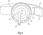
FIG. 4 is a view from below of the part of the dispenser shown inFIGS. 2 and 3 ; -
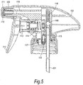
FIG. 5 is a quasi-sectional view of the part of the dispenser ofFIGS. 2 to 4 ; and -
FIG. 6 is a cross-sectional view of a portion of the dispenser ofFIGS. 2 to 5 showing the pressure-relief valve and the filter. -
FIG. 1 shows an exploded view of part of a known spray dispenser, as described inGB2391862 spray dispenser 1 comprises a flexible,inner vessel 6 in the form of a bag of a plastics material, formed with a convex bottom 7. Theinner vessel 6 has aneck region 5 in which the plastics material is welded to acollar 8, thus forming anannular weld 10 around the circumference of thecollar 8. A bung 12 is inserted into thecollar 8, thus forming a seal between bung and collar. A dip tube (shown as dotted line 9 inFIG. 1 ) is inserted into thevessel 6 via an aperture inbung 12, there being a seal formed between the dip tube 9 and the bung 12 due to diameter of the dip tube and the resilient nature of the bung. Theinner vessel 6 is provided with liquid (not shown) to be dispensed therefrom. Theinner vessel 6 is supported by an outer container in the form of a substantially rigid, generally cylindrical plastics bottle 2. The plastics bottle 2 abuts anannular lip 14 provided oncollar 8, therefore providing support to theinner vessel 6. The plastics bottle 2 is provided with anaperture 16 which facilitates the passage of air into the plastics bottle and into the space surrounding theinner vessel 6. - The dip tube 9 is associated with a trigger assembly (not shown). The trigger assembly used in the prior art device conforms in general to known trigger-actuated pressure pump arrangements. Actuation of the trigger assembly creates a differential in pressure which draws liquid along the dip tube and dispenses it as a spray. The arrangement of the bung and trigger arrangement ensures that any exhaust air or back pressure does not result in ambient air being drawn into the collapsible container. This inhibits contamination of the contents of the
vessel 6 by external contaminants. Because theinner vessel 6 collapses as liquid is dispensed, little or no back pressure exists in the flexible inner vessel.Aperture 16 prevents a partial vacuum being created between the interior wall of plastics bottle 2 and thevessel 6 as thevessel 6 collapses. - An example of a dispenser in accordance with the present invention will now be described with reference to
FIGS. 2 to 6 . The dispenser comprises a collapsible inner vessel (not shown) similar to that described above in relation to the prior art and as described inGB2391862 GB2391862 GB2391862 - The dispenser of the present invention comprises a dip tube (101) which extends from the bottom of the collapsible container (not shown) into a dispenser head (102). The dip tube (101) passes through cap (106) via an aperture (not shown) in a plate (103). The dip tube (101) is in sealing engagement with the plate (103) at the aperture (not shown) so as to inhibit passage of air into the container of liquid. The dip tube (101) is in fluid communication with dispenser channel (118). Dispenser channel (118) is provided with a ball valve (108), the operation of which will be described below. Dispenser channel (118) is in fluid communication with dispenser channel (119) which has a nozzle (109) at one end. Nozzle (109) comprises a nozzle aperture (110) for the spray dispensing of fluid and a spray control member (111). The spray control member (111) is mounted relative to the nozzle aperture (110) so that said member is operable to control the spray emitted from the dispenser, as is well-known to those skilled in the art. The spray dispenser further comprises a trigger (112) which is associated with a piston (113). A spring (114) biases the piston and trigger into a forward position.
- Liquid is dispensed from the dispenser essentially as described above in relation to the prior art dispenser. Pulling the trigger (112) causes liquid to be pumped from the dispenser as a spray. On releasing the trigger, the
spring 114 urges thepiston 113 into the forward position. This urges liquid up the dip tube (101) ready to be dispensed on the next spray stroke. The ball valve (108) operates so as to permit fluid flow up through the dip tube (101) into the dispenser head (102) for dispensing, but inhibits ingress of contaminants into the container via the dip tube (101). - The arrangement of the dip tube (101) and sealing member (107) is slightly different from that shown above in
FIG. 1 in relation to the prior art. The sealing member (107) comprises an annular washer which, in use, engages with the annular, uppermost surface of the neck of the bottle (not shown) to produce a seal. - The arrangement and operation of the pressure-relief valve and filter are now described. A venting aperture (104) is provided in plate (103). The venting aperture (104) is in gas flow communication with the pressure-relief valve (115) and filter (105), with the filter being in a gas flow path between the venting aperture (104) and the pressure-relief valve (115). The filter (105) is located in a filter housing (116) to facilitate ease of handling. The filter is a membrane of hydrophobic material (Gore(R) membrane, W.L. Gore and Associates, Newark, USA), with 0.2 micron pores therein. The filter housing (116) is located in a space formed in the valve housing (117). Such an arrangement facilitates ease of placement of the filter relative to the valve. The
pressure relief valve 115 is a duck-bill valve which is effectively trapped in place by twoparts valve housing 117. The operation of the pressure-relief valve 115 will now be explained briefly. The pressure-relief valve 115 comprises two elasticallydeformable lips lips valve aperture 122, thus relieving the pressure. The one-way valve 115 therefore permits egress of gas associated with the over-pressure and naturally closes in the absence of over-pressure, therefore inhibiting ingress of air and contaminants into the container. The duckbill valve is made from an elastomer which prevents backflow leakage when minimal backpressure is applied. Furthermore, the elastomer is resilient to gamma radiation which is used to sterilise the container and its contents. The duckbill valve also has the advantage that it can be installed easily into a hole and sealed. Those skilled in the art will realise that the properties of the valve (e.g. the pressure differential at which the valve opens to release pressure and the backpressure at which the valve closes) may be readily optimised by changing the thickness of the elastomer, the shape of the valve and the elastomer from which the valve is made. - The filter 105 provides further protection against ingress of contaminants, and also allows passage therethrough of vapour generated by an overpressure but the filter prevents egress of liquid from the container through the filter. The filter is advantageously sited in a flow path between the valve and the contents of the vessel. Whilst it is possible to site the valve in a flow path between the filter and the contents of the vessel, this is not so desirable because the filter may be prone to clogging, which may inhibit egress of vapour in the event of overpressure.
- Those skilled in the art will realise that the present invention is not limited to the type of dispenser mentioned above (i.e. one which comprises a collapsible container sealed to the dispensing mechanism).
- Those skilled in the art will also realise that the present invention is not limited to the particular type of valve shown in the example above. For example, a spring-biased pressure relief valve or a reed valve may be used.
- It will be apparent to those skilled in the art that an actuator other than a trigger may be used. For example, a button or the like may be used.
- Where in the foregoing description, integers or elements are mentioned which have known, obvious or foreseeable equivalents, then such equivalents are herein incorporated as if individually set forth. Reference should be made to the claims for determining the true scope of the present invention, which should be construed so as to encompass any such equivalents. It will also be appreciated by the reader that integers or features of the invention that are described as preferable, advantageous, convenient or the like are optional and do not limit the scope of the independent claims.
Claims (12)
- A dispenser for dispensing liquid, the dispenser comprising:a container for holding the liquid to be dispensed; anda dispensing assembly for extracting liquid from the container, the dispensing assembly comprising:a mechanism for creating a pressure differential for dispensing the liquid;a pressure-relief valve constructed to release excessive pressure in the container, wherein the pressure-relief valve is selected from the group consisting of a swing valve, a ball check valve, and a duckbill valve, the pressure-relief valve being closed in the absence of excessive pressure in the container to prevent air and contaminants from entering the container;a filter housing removably coupled with the dispensing assembly; anda filter arranged in the filter housing to permit exit of gas from the container through the filter and through the pressure-relief valve, the filter inhibiting passage of liquid from the container through the filter, wherein:the filter is in a gas flow path between the interior of the container and the pressure-relief valve, orthe pressure-relief valve is in a gas flow path between the interior of the container and the filter.
- The dispenser of claim 1, wherein the container comprises a collapsible liquid-containment portion.
- The dispenser of claim 1 or 2, wherein the collapsible liquid-containment portion is constructed to collapse when liquid is dispensed from the container.
- The dispenser of claims 1 to 3, wherein the dispenser comprises a housing for enclosing the container.
- The dispenser of claims 1 to 4, wherein the container comprises a seal-forming surface comprising a collar.
- The dispenser of claims 1 to 5, wherein the collar is more rigid than the liquid-containing portion.
- The dispenser of claims 1 to 6, wherein the dispensing assembly comprises a sealing member that forms a seal against the seal-forming surface of the container.
- The dispenser of claims 1 to 7, wherein the dispenser is closed with a closure that prevents access to the container.
- The dispenser of claims 1 to 8, wherein the filter comprises hydrophobic membrane.
- The dispenser of claims 1 to 9, wherein the filter has a pore size of 10 microns or smaller.
- The dispenser of claims 1 to 10, wherein the filter has a pore size of 5 microns or smaller.
- The dispenser of claims 1 to 11, wherein the valve is a duckbill valve.
Priority Applications (6)
| Application Number | Priority Date | Filing Date | Title |
|---|---|---|---|
| SM20210309T SMT202100309T1 (en) | 2009-10-19 | 2010-10-19 | Dispenser |
| EP18213218.3A EP3495048B1 (en) | 2009-10-19 | 2010-10-19 | Spray dispenser |
| SI201032070T SI3320979T1 (en) | 2009-10-19 | 2010-10-19 | Dispenser |
| RS20210551A RS61938B1 (en) | 2009-10-19 | 2010-10-19 | Dispenser |
| PL17205262T PL3320979T3 (en) | 2009-10-19 | 2010-10-19 | DISPENSER |
| HRP20210755TT HRP20210755T1 (en) | 2009-10-19 | 2021-05-12 | DISTRIBUTOR |
Applications Claiming Priority (3)
| Application Number | Priority Date | Filing Date | Title |
|---|---|---|---|
| GB0918296.5A GB2474520B (en) | 2009-10-19 | 2009-10-19 | Spray dispenser |
| EP10777084.4A EP2490821B1 (en) | 2009-10-19 | 2010-10-19 | Spray dispenser |
| PCT/GB2010/051761 WO2011048411A1 (en) | 2009-10-19 | 2010-10-19 | Spray dispenser |
Related Parent Applications (1)
| Application Number | Title | Priority Date | Filing Date |
|---|---|---|---|
| EP10777084.4A Division EP2490821B1 (en) | 2009-10-19 | 2010-10-19 | Spray dispenser |
Related Child Applications (2)
| Application Number | Title | Priority Date | Filing Date |
|---|---|---|---|
| EP18213218.3A Division-Into EP3495048B1 (en) | 2009-10-19 | 2010-10-19 | Spray dispenser |
| EP18213218.3A Division EP3495048B1 (en) | 2009-10-19 | 2010-10-19 | Spray dispenser |
Publications (2)
| Publication Number | Publication Date |
|---|---|
| EP3320979A1 true EP3320979A1 (en) | 2018-05-16 |
| EP3320979B1 EP3320979B1 (en) | 2021-03-24 |
Family
ID=41462572
Family Applications (3)
| Application Number | Title | Priority Date | Filing Date |
|---|---|---|---|
| EP17205262.3A Active EP3320979B1 (en) | 2009-10-19 | 2010-10-19 | Dispenser |
| EP18213218.3A Active EP3495048B1 (en) | 2009-10-19 | 2010-10-19 | Spray dispenser |
| EP10777084.4A Active EP2490821B1 (en) | 2009-10-19 | 2010-10-19 | Spray dispenser |
Family Applications After (2)
| Application Number | Title | Priority Date | Filing Date |
|---|---|---|---|
| EP18213218.3A Active EP3495048B1 (en) | 2009-10-19 | 2010-10-19 | Spray dispenser |
| EP10777084.4A Active EP2490821B1 (en) | 2009-10-19 | 2010-10-19 | Spray dispenser |
Country Status (20)
| Country | Link |
|---|---|
| US (6) | US9211557B2 (en) |
| EP (3) | EP3320979B1 (en) |
| JP (1) | JP5889194B2 (en) |
| CN (1) | CN102665927B (en) |
| AU (1) | AU2010309527C1 (en) |
| CY (2) | CY1120263T1 (en) |
| DK (2) | DK2490821T3 (en) |
| ES (3) | ES2981554T3 (en) |
| GB (1) | GB2474520B (en) |
| HR (2) | HRP20180429T1 (en) |
| HU (2) | HUE054138T2 (en) |
| LT (2) | LT2490821T (en) |
| MY (2) | MY191493A (en) |
| NO (1) | NO2490821T3 (en) |
| PL (3) | PL2490821T3 (en) |
| PT (2) | PT2490821T (en) |
| RS (2) | RS61938B1 (en) |
| SI (2) | SI2490821T1 (en) |
| SM (2) | SMT201800207T1 (en) |
| WO (1) | WO2011048411A1 (en) |
Families Citing this family (23)
| Publication number | Priority date | Publication date | Assignee | Title |
|---|---|---|---|---|
| GB2474520B (en) | 2009-10-19 | 2015-08-26 | London & General Packaging Ltd | Spray dispenser |
| IT1401659B1 (en) * | 2010-09-16 | 2013-08-02 | Guala Dispensing Spa | DISTRIBUTION DEVICE FOR LIQUIDS |
| FR2976981B1 (en) * | 2011-06-27 | 2013-07-05 | Promens Sa | SYSTEM FOR CLOSING A LOW PRESSURE DISTRIBUTION DEVICE OF A PASTY LIQUID PRODUCT |
| US9950302B1 (en) | 2014-01-13 | 2018-04-24 | Crossford International, Llc | Stand-alone chemical dispenser |
| DE202014001720U1 (en) * | 2014-02-27 | 2015-03-02 | Gerhard Brugger | donor |
| USD750333S1 (en) | 2014-12-23 | 2016-02-23 | Crossford International, Llc | Chemical cleaning apparatus |
| US9815680B2 (en) * | 2015-10-13 | 2017-11-14 | Harald George Tomesch | Wine dispenser that preserves wine quality by reducing oxidation of contained wine when the dispenser is partially full |
| US9533331B1 (en) | 2015-10-28 | 2017-01-03 | Crossford International, Llc | Hand-held solid chemical applicator |
| CN107457104B (en) * | 2016-06-06 | 2023-07-14 | 丁要武 | Anti-overflow liquid emulsion pump |
| DE102017114161A1 (en) * | 2017-06-26 | 2018-12-27 | Lcm Gmbh | Method and device for spraying a liquid onto a plate-shaped workpiece |
| EP3427839B1 (en) * | 2017-07-13 | 2020-12-02 | Aptar Radolfzell GmbH | Liquid dispenser with ventilated bottle and applicator head for same |
| US10358270B1 (en) | 2018-05-31 | 2019-07-23 | Camelbak Products, Llc | Closure assemblies and drink containers including the same |
| USD864658S1 (en) | 2018-05-31 | 2019-10-29 | Camelbak Products, Llc | Beverage container closure |
| US10532862B2 (en) | 2018-06-19 | 2020-01-14 | Camelbak Products, Llc | Closure assemblies with distinct dispensing modes and drink containers including the same |
| USD881639S1 (en) | 2018-06-19 | 2020-04-21 | Camelbak Products, Llc | Beverage container closure |
| FR3097451B1 (en) * | 2019-06-21 | 2021-10-01 | Michel Camilleri | DISPOSABLE MICROPOROUS VENT BUCKET |
| US11219910B2 (en) * | 2019-09-10 | 2022-01-11 | Silgan Dispensing Systems Corporation | Trigger sprayer with improved venting system and methods of using the same |
| EP3821987B1 (en) * | 2019-11-15 | 2022-09-28 | Aptar Radolfzell GmbH | Fluid dispenser with bottle ventilation |
| GB202011946D0 (en) * | 2020-07-31 | 2020-09-16 | Obrist Closures Switzerland | Valve |
| CN112138889B (en) * | 2020-08-05 | 2021-10-26 | 养生堂(安吉)化妆品有限公司 | Sprayer and maintenance method thereof |
| WO2022112889A1 (en) * | 2020-11-24 | 2022-06-02 | Guala Dispensing S.P.A. | Trigger dispensing device |
| US12502683B2 (en) | 2022-07-26 | 2025-12-23 | Shanghai Keto Tech Co., Ltd. | Liquid dispenser |
| CN218282196U (en) * | 2022-07-29 | 2023-01-13 | 广州沫和车制造有限公司 | Quick butt joint fluid reservoir and leak protection foam watering can |
Citations (3)
| Publication number | Priority date | Publication date | Assignee | Title |
|---|---|---|---|---|
| GB1563749A (en) * | 1976-10-20 | 1980-03-26 | Oreal | Atomizing dispenser |
| GB2106877A (en) * | 1981-08-17 | 1983-04-20 | Eugene Meierhoefer | Sterile solution delivery and venting device |
| DE102004050679A1 (en) * | 2004-10-13 | 2006-04-20 | Ing. Erich Pfeiffer Gmbh | metering |
Family Cites Families (47)
| Publication number | Priority date | Publication date | Assignee | Title |
|---|---|---|---|---|
| US4093124A (en) * | 1976-07-26 | 1978-06-06 | L'oreal | Atomizer with air inlet valve |
| AU622426B2 (en) | 1987-12-11 | 1992-04-09 | Abbott Laboratories | Assay using template-dependent nucleic acid probe reorganization |
| US5183184A (en) * | 1988-10-07 | 1993-02-02 | Ryder International Corporation | Liquid dispenser nozzle assembly |
| US4934545A (en) * | 1989-01-19 | 1990-06-19 | Abbott Laboratories | Closure with microbial filter |
| US4930667A (en) * | 1989-01-23 | 1990-06-05 | Steiner Company, Inc. | Breathing device for soap dispenser |
| US5074440A (en) * | 1990-07-16 | 1991-12-24 | Alcon Laboratories, Inc. | Container for dispensing preservative-free preparations |
| US5373972A (en) * | 1991-11-15 | 1994-12-20 | Jsp Partners, L.P. | Preservative-free sterile fluid dispensing system |
| US5310094A (en) | 1991-11-15 | 1994-05-10 | Jsp Partners, L.P. | Preservative free sterile fluid dispensing system |
| JP2583171Y2 (en) * | 1992-10-13 | 1998-10-15 | 株式会社吉野工業所 | Trigger type liquid ejector |
| DE4321927C2 (en) * | 1993-07-01 | 1998-07-09 | Sartorius Gmbh | Filter unit with degassing device |
| US5398846A (en) * | 1993-08-20 | 1995-03-21 | S. C. Johnson & Son, Inc. | Assembly for simultaneous dispensing of multiple fluids |
| US6123900A (en) | 1993-10-28 | 2000-09-26 | Vellutato; Arthur L. | Method of sterilization |
| JP3572712B2 (en) | 1995-03-15 | 2004-10-06 | 東洋製罐株式会社 | Discharge mode switching device for pump dispenser |
| US5584409A (en) * | 1995-09-18 | 1996-12-17 | Chemberlen; Christopher H. | One direction ventilation valves |
| US5605257A (en) * | 1996-03-04 | 1997-02-25 | Beard; Walter C. | Sterile liquid squeeze-bottle-type dispenser |
| DE19610457A1 (en) * | 1996-03-16 | 1997-09-18 | Pfeiffer Erich Gmbh & Co Kg | Discharge device for media |
| CN1222100A (en) * | 1996-04-12 | 1999-07-07 | 普罗格特-甘布尔公司 | Naturally vented pump-pressed dispensing device |
| US5752629A (en) * | 1996-04-12 | 1998-05-19 | The Procter & Gamble Company | Passive venting for pump dispensing device |
| GB2333129A (en) * | 1998-09-15 | 1999-07-14 | Thomas David White | Spray dispenser with collapsible container |
| US6073812A (en) * | 1999-01-25 | 2000-06-13 | Steris Inc. | Filtered venting system for liquid containers which are susceptible to contamination from external bioburden |
| US6095377A (en) * | 1999-03-26 | 2000-08-01 | Calmar Inc. | Liquid dispensing pump |
| CA2351150C (en) * | 2001-06-21 | 2006-07-11 | 1361215 Ontario Inc. | Pressure sensitive one-way valve |
| CN1283365C (en) * | 2001-09-21 | 2006-11-08 | 艾里希普费弗工程师有限公司 | Dosing device with a medium container and a pump mechanism for the container |
| WO2003026804A1 (en) * | 2001-09-21 | 2003-04-03 | Ing. Erich Pfeiffer Gmbh | Dosing device with a medium reservoir and a pump device |
| US6766816B2 (en) * | 2001-10-03 | 2004-07-27 | Hunter Group, Inc. | Collapsible dispensing system |
| JP2003266073A (en) * | 2002-03-13 | 2003-09-24 | Sanyo Electric Co Ltd | Electrolyzed water generator |
| GB2391862C (en) | 2002-08-13 | 2007-01-11 | Shield Medicare Ltd | Spray dispenser assembly and vessel therefor |
| US6837400B2 (en) * | 2003-03-07 | 2005-01-04 | Nalge Nunc International Corporation | Solvent identification bottle with adjustable dispensing feature |
| US20050095283A1 (en) | 2003-09-16 | 2005-05-05 | Aphios Corporation | Compositions and methods for topically treating diseases |
| DE102004044344A1 (en) * | 2004-09-09 | 2006-03-30 | Ing. Erich Pfeiffer Gmbh | metering |
| BRPI0516150A (en) * | 2004-09-27 | 2008-08-26 | Medical Instill Tech Inc | dispenser to release a substance |
| DE102004050977A1 (en) * | 2004-10-14 | 2006-04-20 | Ing. Erich Pfeiffer Gmbh | Dosing device for at least one medium |
| ATE383205T1 (en) * | 2005-02-22 | 2008-01-15 | Pfeiffer Erich Gmbh & Co Kg | DISPENSER FOR MEDIA AND ASSEMBLY METHOD THEREOF |
| EP1779933A1 (en) * | 2005-10-26 | 2007-05-02 | The Procter and Gamble Company | Dispenser for a liquid |
| GB2436350A (en) | 2006-03-22 | 2007-09-26 | Shield Medicare Ltd | Multi compartment dispenser with gas cartridge activator and dispensing inhibitor |
| ITBO20060856A1 (en) * | 2006-12-15 | 2008-06-16 | Aroma System Srl | FLAT UNIDIRECTIONAL BREATHER VALVE. |
| ITRM20070275A1 (en) * | 2007-05-17 | 2008-11-18 | Federighi Federigo | MULTIDOSE DISPENSER BOTTLE FOR PRESERVATIVE-FREE LIQUID PREPARATIONS. |
| US20090169693A1 (en) * | 2007-12-27 | 2009-07-02 | Hoffman Karl K | Interior-mountable pressure relief valve |
| FR2929249B1 (en) * | 2008-03-27 | 2012-02-17 | Rexam Pharma La Verpilliere | DEVICE FOR DISPENSING LIQUID CONTAINED IN A RESERVOIR |
| DE102008034244A1 (en) * | 2008-07-23 | 2010-03-04 | Brückner, Henry | Dosing pump e.g. piston pump, for use in liquid dispenser for dosing of e.g. soap, is arranged below cartridge, where air intake is arranged above liquid level, and upper end of standpipe and ventilation valve are arranged outside of liquid |
| FR2937019B1 (en) * | 2008-10-15 | 2012-06-08 | Rexam Pharma La Verpilliere | LIQUID DISPENSING DEVICE WITH SEALING BODY HAVING AN ELASTOMERIC PART |
| JP5531013B2 (en) * | 2009-05-22 | 2014-06-25 | 大塚製薬株式会社 | Eye drops container |
| FR2950036B1 (en) * | 2009-09-11 | 2011-12-16 | Rexam Pharma La Verpilliere | DEVICE FOR DISTRIBUTING LIQUID |
| FR2950037B1 (en) * | 2009-09-11 | 2011-12-16 | Rexam Pharma La Verpilliere | DEVICE FOR DISTRIBUTING LIQUID |
| GB2474520B (en) | 2009-10-19 | 2015-08-26 | London & General Packaging Ltd | Spray dispenser |
| FR2964089B1 (en) * | 2010-08-26 | 2014-01-10 | Airlessystems | FLUID PRODUCT DISPENSER. |
| US9833798B2 (en) * | 2014-03-10 | 2017-12-05 | Matthew Tait Phillips | Dispenser |
-
2009
- 2009-10-19 GB GB0918296.5A patent/GB2474520B/en active Active
-
2010
- 2010-10-19 SM SM20180207T patent/SMT201800207T1/en unknown
- 2010-10-19 PT PT107770844T patent/PT2490821T/en unknown
- 2010-10-19 NO NO10777084A patent/NO2490821T3/no unknown
- 2010-10-19 EP EP17205262.3A patent/EP3320979B1/en active Active
- 2010-10-19 JP JP2012534776A patent/JP5889194B2/en active Active
- 2010-10-19 RS RS20210551A patent/RS61938B1/en unknown
- 2010-10-19 ES ES18213218T patent/ES2981554T3/en active Active
- 2010-10-19 SM SM20210309T patent/SMT202100309T1/en unknown
- 2010-10-19 EP EP18213218.3A patent/EP3495048B1/en active Active
- 2010-10-19 PL PL10777084T patent/PL2490821T3/en unknown
- 2010-10-19 ES ES17205262T patent/ES2873673T3/en active Active
- 2010-10-19 PL PL17205262T patent/PL3320979T3/en unknown
- 2010-10-19 MY MYPI2018000300A patent/MY191493A/en unknown
- 2010-10-19 EP EP10777084.4A patent/EP2490821B1/en active Active
- 2010-10-19 LT LTEP10777084.4T patent/LT2490821T/en unknown
- 2010-10-19 HU HUE17205262A patent/HUE054138T2/en unknown
- 2010-10-19 MY MYPI2012001722A patent/MY164984A/en unknown
- 2010-10-19 HU HUE10777084A patent/HUE037445T2/en unknown
- 2010-10-19 HR HRP20180429TT patent/HRP20180429T1/en unknown
- 2010-10-19 WO PCT/GB2010/051761 patent/WO2011048411A1/en not_active Ceased
- 2010-10-19 PL PL18213218.3T patent/PL3495048T3/en unknown
- 2010-10-19 CN CN201080047057.7A patent/CN102665927B/en active Active
- 2010-10-19 RS RS20180307A patent/RS57181B1/en unknown
- 2010-10-19 DK DK10777084.4T patent/DK2490821T3/en active
- 2010-10-19 US US13/502,954 patent/US9211557B2/en active Active
- 2010-10-19 PT PT172052623T patent/PT3320979T/en unknown
- 2010-10-19 SI SI201031652T patent/SI2490821T1/en unknown
- 2010-10-19 DK DK17205262.3T patent/DK3320979T3/en active
- 2010-10-19 ES ES10777084.4T patent/ES2662531T3/en active Active
- 2010-10-19 AU AU2010309527A patent/AU2010309527C1/en active Active
- 2010-10-19 LT LTEP17205262.3T patent/LT3320979T/en unknown
- 2010-10-19 SI SI201032070T patent/SI3320979T1/en unknown
-
2015
- 2015-11-12 US US14/939,810 patent/US9649648B2/en active Active
-
2017
- 2017-04-03 US US15/477,875 patent/US10556247B2/en active Active
-
2018
- 2018-03-12 CY CY20181100296T patent/CY1120263T1/en unknown
-
2020
- 2020-01-06 US US16/734,917 patent/US11192129B2/en active Active
-
2021
- 2021-05-11 CY CY20211100398T patent/CY1124165T1/en unknown
- 2021-05-12 HR HRP20210755TT patent/HRP20210755T1/en unknown
- 2021-11-02 US US17/517,486 patent/US11745196B2/en active Active
-
2023
- 2023-07-17 US US18/353,311 patent/US12390823B2/en active Active
Patent Citations (3)
| Publication number | Priority date | Publication date | Assignee | Title |
|---|---|---|---|---|
| GB1563749A (en) * | 1976-10-20 | 1980-03-26 | Oreal | Atomizing dispenser |
| GB2106877A (en) * | 1981-08-17 | 1983-04-20 | Eugene Meierhoefer | Sterile solution delivery and venting device |
| DE102004050679A1 (en) * | 2004-10-13 | 2006-04-20 | Ing. Erich Pfeiffer Gmbh | metering |
Also Published As
Similar Documents
| Publication | Publication Date | Title |
|---|---|---|
| US12390823B2 (en) | Dispenser | |
| KR101560582B1 (en) | Device with co-molded closure, one-way valve and variable-volume storage chamber, and related method | |
| JPH05500937A (en) | Containers for dispensing preservative-free preparations | |
| KR102077139B1 (en) | Device having a manual pump for packaging and dispensing fluid products | |
| KR960701624A (en) | Preservative-FREE STERILE FLUID DISPENSING SYSTEM | |
| ZA200302496B (en) | Fluid dispensing closure. | |
| BR0212718B1 (en) | dosing device with a media reservoir as well as with a pumping device. | |
| US10919676B2 (en) | Lid with ventilation system | |
| GB2202836A (en) | Dispensing container closure | |
| US8567647B2 (en) | Multifunctional seal device for a valve for a drinking receptacle | |
| WO2013153356A1 (en) | Liquid dispensing system | |
| WO2006063360A2 (en) | Container and valve assembly for storing and dispensing substances, and related method | |
| ES2526807T3 (en) | Dispenser featuring a variable volume storage chamber and an unidirectional valve assembly that can be used to dispense creams and other substances | |
| KR0153460B1 (en) | System for Dispensing Chemical Sterilizers from Reservoir |
Legal Events
| Date | Code | Title | Description |
|---|---|---|---|
| PUAI | Public reference made under article 153(3) epc to a published international application that has entered the european phase |
Free format text: ORIGINAL CODE: 0009012 |
|
| STAA | Information on the status of an ep patent application or granted ep patent |
Free format text: STATUS: THE APPLICATION HAS BEEN PUBLISHED |
|
| AC | Divisional application: reference to earlier application |
Ref document number: 2490821 Country of ref document: EP Kind code of ref document: P |
|
| AK | Designated contracting states |
Kind code of ref document: A1 Designated state(s): AL AT BE BG CH CY CZ DE DK EE ES FI FR GB GR HR HU IE IS IT LI LT LU LV MC MK MT NL NO PL PT RO RS SE SI SK SM TR |
|
| RAP1 | Party data changed (applicant data changed or rights of an application transferred) |
Owner name: ECOLAB USA INC. |
|
| STAA | Information on the status of an ep patent application or granted ep patent |
Free format text: STATUS: REQUEST FOR EXAMINATION WAS MADE |
|
| 17P | Request for examination filed |
Effective date: 20181113 |
|
| RBV | Designated contracting states (corrected) |
Designated state(s): AL AT BE BG CH CY CZ DE DK EE ES FI FR GB GR HR HU IE IS IT LI LT LU LV MC MK MT NL NO PL PT RO RS SE SI SK SM TR |
|
| STAA | Information on the status of an ep patent application or granted ep patent |
Free format text: STATUS: EXAMINATION IS IN PROGRESS |
|
| 17Q | First examination report despatched |
Effective date: 20190308 |
|
| GRAP | Despatch of communication of intention to grant a patent |
Free format text: ORIGINAL CODE: EPIDOSNIGR1 |
|
| STAA | Information on the status of an ep patent application or granted ep patent |
Free format text: STATUS: GRANT OF PATENT IS INTENDED |
|
| INTG | Intention to grant announced |
Effective date: 20201021 |
|
| GRAS | Grant fee paid |
Free format text: ORIGINAL CODE: EPIDOSNIGR3 |
|
| GRAA | (expected) grant |
Free format text: ORIGINAL CODE: 0009210 |
|
| STAA | Information on the status of an ep patent application or granted ep patent |
Free format text: STATUS: THE PATENT HAS BEEN GRANTED |
|
| AC | Divisional application: reference to earlier application |
Ref document number: 2490821 Country of ref document: EP Kind code of ref document: P |
|
| AK | Designated contracting states |
Kind code of ref document: B1 Designated state(s): AL AT BE BG CH CY CZ DE DK EE ES FI FR GB GR HR HU IE IS IT LI LT LU LV MC MK MT NL NO PL PT RO RS SE SI SK SM TR |
|
| REG | Reference to a national code |
Ref country code: GB Ref legal event code: FG4D |
|
| REG | Reference to a national code |
Ref country code: CH Ref legal event code: EP |
|
| REG | Reference to a national code |
Ref country code: DE Ref legal event code: R096 Ref document number: 602010066668 Country of ref document: DE |
|
| REG | Reference to a national code |
Ref country code: IE Ref legal event code: FG4D |
|
| REG | Reference to a national code |
Ref country code: AT Ref legal event code: REF Ref document number: 1373962 Country of ref document: AT Kind code of ref document: T Effective date: 20210415 |
|
| REG | Reference to a national code |
Ref country code: DK Ref legal event code: T3 Effective date: 20210429 |
|
| REG | Reference to a national code |
Ref country code: HR Ref legal event code: TUEP Ref document number: P20210755T Country of ref document: HR |
|
| REG | Reference to a national code |
Ref country code: RO Ref legal event code: EPE |
|
| REG | Reference to a national code |
Ref country code: SE Ref legal event code: TRGR |
|
| REG | Reference to a national code |
Ref country code: FI Ref legal event code: FGE |
|
| REG | Reference to a national code |
Ref country code: PT Ref legal event code: SC4A Ref document number: 3320979 Country of ref document: PT Date of ref document: 20210524 Kind code of ref document: T Free format text: AVAILABILITY OF NATIONAL TRANSLATION Effective date: 20210517 |
|
| REG | Reference to a national code |
Ref country code: NL Ref legal event code: FP |
|
| REG | Reference to a national code |
Ref country code: HR Ref legal event code: T1PR Ref document number: P20210755 Country of ref document: HR |
|
| REG | Reference to a national code |
Ref country code: GR Ref legal event code: EP Ref document number: 20210401197 Country of ref document: GR Effective date: 20210614 |
|
| REG | Reference to a national code |
Ref country code: NO Ref legal event code: T2 Effective date: 20210324 |
|
| REG | Reference to a national code |
Ref country code: EE Ref legal event code: FG4A Ref document number: E020830 Country of ref document: EE Effective date: 20210510 |
|
| REG | Reference to a national code |
Ref country code: SK Ref legal event code: T3 Ref document number: E 37331 Country of ref document: SK |
|
| REG | Reference to a national code |
Ref country code: HU Ref legal event code: AG4A Ref document number: E054138 Country of ref document: HU |
|
| REG | Reference to a national code |
Ref country code: ES Ref legal event code: FG2A Ref document number: 2873673 Country of ref document: ES Kind code of ref document: T3 Effective date: 20211103 |
|
| REG | Reference to a national code |
Ref country code: HR Ref legal event code: ODRP Ref document number: P20210755 Country of ref document: HR Payment date: 20211014 Year of fee payment: 12 |
|
| REG | Reference to a national code |
Ref country code: DE Ref legal event code: R097 Ref document number: 602010066668 Country of ref document: DE |
|
| PLBE | No opposition filed within time limit |
Free format text: ORIGINAL CODE: 0009261 |
|
| STAA | Information on the status of an ep patent application or granted ep patent |
Free format text: STATUS: NO OPPOSITION FILED WITHIN TIME LIMIT |
|
| 26N | No opposition filed |
Effective date: 20220104 |
|
| REG | Reference to a national code |
Ref country code: HR Ref legal event code: ODRP Ref document number: P20210755 Country of ref document: HR Payment date: 20221019 Year of fee payment: 13 |
|
| REG | Reference to a national code |
Ref country code: AT Ref legal event code: UEP Ref document number: 1373962 Country of ref document: AT Kind code of ref document: T Effective date: 20210324 |
|
| PGFP | Annual fee paid to national office [announced via postgrant information from national office to epo] |
Ref country code: ES Payment date: 20221109 Year of fee payment: 13 |
|
| REG | Reference to a national code |
Ref country code: HR Ref legal event code: ODRP Ref document number: P20210755 Country of ref document: HR Payment date: 20230904 Year of fee payment: 14 |
|
| REG | Reference to a national code |
Ref country code: HR Ref legal event code: ODRP Ref document number: P20210755 Country of ref document: HR Payment date: 20240902 Year of fee payment: 15 |
|
| REG | Reference to a national code |
Ref country code: ES Ref legal event code: FD2A Effective date: 20241204 |
|
| PG25 | Lapsed in a contracting state [announced via postgrant information from national office to epo] |
Ref country code: ES Free format text: LAPSE BECAUSE OF NON-PAYMENT OF DUE FEES Effective date: 20231020 |
|
| PG25 | Lapsed in a contracting state [announced via postgrant information from national office to epo] |
Ref country code: ES Free format text: LAPSE BECAUSE OF NON-PAYMENT OF DUE FEES Effective date: 20231020 |
|
| PGFP | Annual fee paid to national office [announced via postgrant information from national office to epo] |
Ref country code: LT Payment date: 20250919 Year of fee payment: 16 |
|
| PGFP | Annual fee paid to national office [announced via postgrant information from national office to epo] |
Ref country code: GR Payment date: 20250911 Year of fee payment: 16 |
|
| PGFP | Annual fee paid to national office [announced via postgrant information from national office to epo] |
Ref country code: NL Payment date: 20250912 Year of fee payment: 16 Ref country code: PL Payment date: 20250808 Year of fee payment: 16 Ref country code: IT Payment date: 20250922 Year of fee payment: 16 |
|
| PGFP | Annual fee paid to national office [announced via postgrant information from national office to epo] |
Ref country code: BE Payment date: 20250917 Year of fee payment: 16 Ref country code: BG Payment date: 20250815 Year of fee payment: 16 Ref country code: GB Payment date: 20250828 Year of fee payment: 16 |
|
| PGFP | Annual fee paid to national office [announced via postgrant information from national office to epo] |
Ref country code: HR Payment date: 20250901 Year of fee payment: 16 |
|
| PGFP | Annual fee paid to national office [announced via postgrant information from national office to epo] |
Ref country code: FR Payment date: 20250808 Year of fee payment: 16 |
|
| PGFP | Annual fee paid to national office [announced via postgrant information from national office to epo] |
Ref country code: SE Payment date: 20250812 Year of fee payment: 16 |
|
| PGFP | Annual fee paid to national office [announced via postgrant information from national office to epo] |
Ref country code: IE Payment date: 20250812 Year of fee payment: 16 Ref country code: EE Payment date: 20250909 Year of fee payment: 16 Ref country code: RS Payment date: 20250924 Year of fee payment: 16 |
|
| PGFP | Annual fee paid to national office [announced via postgrant information from national office to epo] |
Ref country code: RO Payment date: 20250922 Year of fee payment: 16 |
|
| REG | Reference to a national code |
Ref country code: HR Ref legal event code: ODRP Ref document number: P20210755 Country of ref document: HR Payment date: 20250901 Year of fee payment: 16 |
|
| PGFP | Annual fee paid to national office [announced via postgrant information from national office to epo] |
Ref country code: SK Payment date: 20250912 Year of fee payment: 16 |
|
| PGFP | Annual fee paid to national office [announced via postgrant information from national office to epo] |
Ref country code: LV Payment date: 20250819 Year of fee payment: 16 |
|
| PGFP | Annual fee paid to national office [announced via postgrant information from national office to epo] |
Ref country code: SI Payment date: 20250827 Year of fee payment: 16 |
|
| REG | Reference to a national code |
Ref country code: CH Ref legal event code: U11 Free format text: ST27 STATUS EVENT CODE: U-0-0-U10-U11 (AS PROVIDED BY THE NATIONAL OFFICE) Effective date: 20251101 |
|
| PGFP | Annual fee paid to national office [announced via postgrant information from national office to epo] |
Ref country code: MK Payment date: 20250821 Year of fee payment: 16 |
|
| PGFP | Annual fee paid to national office [announced via postgrant information from national office to epo] |
Ref country code: HU Payment date: 20250915 Year of fee payment: 16 |
|
| PGFP | Annual fee paid to national office [announced via postgrant information from national office to epo] |
Ref country code: LU Payment date: 20251016 Year of fee payment: 16 |
|
| PGFP | Annual fee paid to national office [announced via postgrant information from national office to epo] |
Ref country code: PT Payment date: 20251020 Year of fee payment: 16 |
|
| PGFP | Annual fee paid to national office [announced via postgrant information from national office to epo] |
Ref country code: IS Payment date: 20251010 Year of fee payment: 16 Ref country code: DE Payment date: 20250827 Year of fee payment: 16 |
|
| PGFP | Annual fee paid to national office [announced via postgrant information from national office to epo] |
Ref country code: NO Payment date: 20251009 Year of fee payment: 16 Ref country code: MC Payment date: 20251002 Year of fee payment: 16 |
|
| PGFP | Annual fee paid to national office [announced via postgrant information from national office to epo] |
Ref country code: SM Payment date: 20251030 Year of fee payment: 16 Ref country code: AT Payment date: 20250925 Year of fee payment: 16 |
|
| PGFP | Annual fee paid to national office [announced via postgrant information from national office to epo] |
Ref country code: FI Payment date: 20251014 Year of fee payment: 16 Ref country code: DK Payment date: 20251014 Year of fee payment: 16 |
|
| PGFP | Annual fee paid to national office [announced via postgrant information from national office to epo] |
Ref country code: TR Payment date: 20251009 Year of fee payment: 16 Ref country code: AL Payment date: 20251008 Year of fee payment: 16 |
|
| PGFP | Annual fee paid to national office [announced via postgrant information from national office to epo] |
Ref country code: CH Payment date: 20251101 Year of fee payment: 16 |
|
| PGFP | Annual fee paid to national office [announced via postgrant information from national office to epo] |
Ref country code: CY Payment date: 20250919 Year of fee payment: 16 Ref country code: CZ Payment date: 20251006 Year of fee payment: 16 |
|
| PGFP | Annual fee paid to national office [announced via postgrant information from national office to epo] |
Ref country code: MT Payment date: 20251020 Year of fee payment: 16 |