EP3320970A1 - Carrier for synthesis gas production catalyst and production method therefor, synthesis gas production catalyst and production method therefor, and synthesis gas production method - Google Patents
Carrier for synthesis gas production catalyst and production method therefor, synthesis gas production catalyst and production method therefor, and synthesis gas production method Download PDFInfo
- Publication number
- EP3320970A1 EP3320970A1 EP17793820.6A EP17793820A EP3320970A1 EP 3320970 A1 EP3320970 A1 EP 3320970A1 EP 17793820 A EP17793820 A EP 17793820A EP 3320970 A1 EP3320970 A1 EP 3320970A1
- Authority
- EP
- European Patent Office
- Prior art keywords
- catalyst
- carrier
- synthesis gas
- magnesium oxide
- mgo
- Prior art date
- Legal status (The legal status is an assumption and is not a legal conclusion. Google has not performed a legal analysis and makes no representation as to the accuracy of the status listed.)
- Granted
Links
Images

Classifications
-
- B—PERFORMING OPERATIONS; TRANSPORTING
- B01—PHYSICAL OR CHEMICAL PROCESSES OR APPARATUS IN GENERAL
- B01J—CHEMICAL OR PHYSICAL PROCESSES, e.g. CATALYSIS OR COLLOID CHEMISTRY; THEIR RELEVANT APPARATUS
- B01J21/00—Catalysts comprising the elements, oxides, or hydroxides of magnesium, boron, aluminium, carbon, silicon, titanium, zirconium, or hafnium
- B01J21/10—Magnesium; Oxides or hydroxides thereof
-
- B—PERFORMING OPERATIONS; TRANSPORTING
- B01—PHYSICAL OR CHEMICAL PROCESSES OR APPARATUS IN GENERAL
- B01J—CHEMICAL OR PHYSICAL PROCESSES, e.g. CATALYSIS OR COLLOID CHEMISTRY; THEIR RELEVANT APPARATUS
- B01J37/00—Processes, in general, for preparing catalysts; Processes, in general, for activation of catalysts
- B01J37/02—Impregnation, coating or precipitation
- B01J37/0201—Impregnation
- B01J37/0207—Pretreatment of the support
-
- B—PERFORMING OPERATIONS; TRANSPORTING
- B01—PHYSICAL OR CHEMICAL PROCESSES OR APPARATUS IN GENERAL
- B01J—CHEMICAL OR PHYSICAL PROCESSES, e.g. CATALYSIS OR COLLOID CHEMISTRY; THEIR RELEVANT APPARATUS
- B01J23/00—Catalysts comprising metals or metal oxides or hydroxides, not provided for in group B01J21/00
- B01J23/02—Catalysts comprising metals or metal oxides or hydroxides, not provided for in group B01J21/00 of the alkali- or alkaline earth metals or beryllium
-
- B—PERFORMING OPERATIONS; TRANSPORTING
- B01—PHYSICAL OR CHEMICAL PROCESSES OR APPARATUS IN GENERAL
- B01J—CHEMICAL OR PHYSICAL PROCESSES, e.g. CATALYSIS OR COLLOID CHEMISTRY; THEIR RELEVANT APPARATUS
- B01J23/00—Catalysts comprising metals or metal oxides or hydroxides, not provided for in group B01J21/00
- B01J23/38—Catalysts comprising metals or metal oxides or hydroxides, not provided for in group B01J21/00 of noble metals
- B01J23/40—Catalysts comprising metals or metal oxides or hydroxides, not provided for in group B01J21/00 of noble metals of the platinum group metals
- B01J23/46—Ruthenium, rhodium, osmium or iridium
- B01J23/462—Ruthenium
-
- B—PERFORMING OPERATIONS; TRANSPORTING
- B01—PHYSICAL OR CHEMICAL PROCESSES OR APPARATUS IN GENERAL
- B01J—CHEMICAL OR PHYSICAL PROCESSES, e.g. CATALYSIS OR COLLOID CHEMISTRY; THEIR RELEVANT APPARATUS
- B01J23/00—Catalysts comprising metals or metal oxides or hydroxides, not provided for in group B01J21/00
- B01J23/38—Catalysts comprising metals or metal oxides or hydroxides, not provided for in group B01J21/00 of noble metals
- B01J23/40—Catalysts comprising metals or metal oxides or hydroxides, not provided for in group B01J21/00 of noble metals of the platinum group metals
- B01J23/46—Ruthenium, rhodium, osmium or iridium
- B01J23/464—Rhodium
-
- B—PERFORMING OPERATIONS; TRANSPORTING
- B01—PHYSICAL OR CHEMICAL PROCESSES OR APPARATUS IN GENERAL
- B01J—CHEMICAL OR PHYSICAL PROCESSES, e.g. CATALYSIS OR COLLOID CHEMISTRY; THEIR RELEVANT APPARATUS
- B01J23/00—Catalysts comprising metals or metal oxides or hydroxides, not provided for in group B01J21/00
- B01J23/38—Catalysts comprising metals or metal oxides or hydroxides, not provided for in group B01J21/00 of noble metals
- B01J23/54—Catalysts comprising metals or metal oxides or hydroxides, not provided for in group B01J21/00 of noble metals combined with metals, oxides or hydroxides provided for in groups B01J23/02 - B01J23/36
- B01J23/56—Platinum group metals
- B01J23/58—Platinum group metals with alkali- or alkaline earth metals
-
- B—PERFORMING OPERATIONS; TRANSPORTING
- B01—PHYSICAL OR CHEMICAL PROCESSES OR APPARATUS IN GENERAL
- B01J—CHEMICAL OR PHYSICAL PROCESSES, e.g. CATALYSIS OR COLLOID CHEMISTRY; THEIR RELEVANT APPARATUS
- B01J35/00—Catalysts, in general, characterised by their form or physical properties
- B01J35/30—Catalysts, in general, characterised by their form or physical properties characterised by their physical properties
- B01J35/396—Distribution of the active metal ingredient
-
- B—PERFORMING OPERATIONS; TRANSPORTING
- B01—PHYSICAL OR CHEMICAL PROCESSES OR APPARATUS IN GENERAL
- B01J—CHEMICAL OR PHYSICAL PROCESSES, e.g. CATALYSIS OR COLLOID CHEMISTRY; THEIR RELEVANT APPARATUS
- B01J35/00—Catalysts, in general, characterised by their form or physical properties
- B01J35/60—Catalysts, in general, characterised by their form or physical properties characterised by their surface properties or porosity
- B01J35/61—Surface area
- B01J35/612—Surface area less than 10 m2/g
-
- B—PERFORMING OPERATIONS; TRANSPORTING
- B01—PHYSICAL OR CHEMICAL PROCESSES OR APPARATUS IN GENERAL
- B01J—CHEMICAL OR PHYSICAL PROCESSES, e.g. CATALYSIS OR COLLOID CHEMISTRY; THEIR RELEVANT APPARATUS
- B01J37/00—Processes, in general, for preparing catalysts; Processes, in general, for activation of catalysts
- B01J37/02—Impregnation, coating or precipitation
- B01J37/0201—Impregnation
-
- B—PERFORMING OPERATIONS; TRANSPORTING
- B01—PHYSICAL OR CHEMICAL PROCESSES OR APPARATUS IN GENERAL
- B01J—CHEMICAL OR PHYSICAL PROCESSES, e.g. CATALYSIS OR COLLOID CHEMISTRY; THEIR RELEVANT APPARATUS
- B01J37/00—Processes, in general, for preparing catalysts; Processes, in general, for activation of catalysts
- B01J37/02—Impregnation, coating or precipitation
- B01J37/0215—Coating
- B01J37/0221—Coating of particles
-
- B—PERFORMING OPERATIONS; TRANSPORTING
- B01—PHYSICAL OR CHEMICAL PROCESSES OR APPARATUS IN GENERAL
- B01J—CHEMICAL OR PHYSICAL PROCESSES, e.g. CATALYSIS OR COLLOID CHEMISTRY; THEIR RELEVANT APPARATUS
- B01J37/00—Processes, in general, for preparing catalysts; Processes, in general, for activation of catalysts
- B01J37/08—Heat treatment
-
- C—CHEMISTRY; METALLURGY
- C01—INORGANIC CHEMISTRY
- C01B—NON-METALLIC ELEMENTS; COMPOUNDS THEREOF; METALLOIDS OR COMPOUNDS THEREOF NOT COVERED BY SUBCLASS C01C
- C01B3/00—Hydrogen; Gaseous mixtures containing hydrogen; Separation of hydrogen from mixtures containing it; Purification of hydrogen; Reversible storage of hydrogen
- C01B3/02—Production of hydrogen; Production of gaseous mixtures containing hydrogen
- C01B3/32—Production of hydrogen; Production of gaseous mixtures containing hydrogen by reaction of gaseous or liquid organic compounds with gasifying agents, e.g. water, carbon dioxide or air
- C01B3/34—Production of hydrogen; Production of gaseous mixtures containing hydrogen by reaction of gaseous or liquid organic compounds with gasifying agents, e.g. water, carbon dioxide or air by reaction of hydrocarbons with gasifying agents
- C01B3/38—Production of hydrogen; Production of gaseous mixtures containing hydrogen by reaction of gaseous or liquid organic compounds with gasifying agents, e.g. water, carbon dioxide or air by reaction of hydrocarbons with gasifying agents using catalysts
- C01B3/40—Production of hydrogen; Production of gaseous mixtures containing hydrogen by reaction of gaseous or liquid organic compounds with gasifying agents, e.g. water, carbon dioxide or air by reaction of hydrocarbons with gasifying agents using catalysts characterised by the catalyst
-
- C—CHEMISTRY; METALLURGY
- C01—INORGANIC CHEMISTRY
- C01B—NON-METALLIC ELEMENTS; COMPOUNDS THEREOF; METALLOIDS OR COMPOUNDS THEREOF NOT COVERED BY SUBCLASS C01C
- C01B32/00—Carbon; Compounds thereof
- C01B32/40—Carbon monoxide
-
- B—PERFORMING OPERATIONS; TRANSPORTING
- B01—PHYSICAL OR CHEMICAL PROCESSES OR APPARATUS IN GENERAL
- B01J—CHEMICAL OR PHYSICAL PROCESSES, e.g. CATALYSIS OR COLLOID CHEMISTRY; THEIR RELEVANT APPARATUS
- B01J2235/00—Indexing scheme associated with group B01J35/00, related to the analysis techniques used to determine the catalysts form or properties
-
- B—PERFORMING OPERATIONS; TRANSPORTING
- B01—PHYSICAL OR CHEMICAL PROCESSES OR APPARATUS IN GENERAL
- B01J—CHEMICAL OR PHYSICAL PROCESSES, e.g. CATALYSIS OR COLLOID CHEMISTRY; THEIR RELEVANT APPARATUS
- B01J2235/00—Indexing scheme associated with group B01J35/00, related to the analysis techniques used to determine the catalysts form or properties
- B01J2235/30—Scanning electron microscopy; Transmission electron microscopy
-
- C—CHEMISTRY; METALLURGY
- C01—INORGANIC CHEMISTRY
- C01B—NON-METALLIC ELEMENTS; COMPOUNDS THEREOF; METALLOIDS OR COMPOUNDS THEREOF NOT COVERED BY SUBCLASS C01C
- C01B2203/00—Integrated processes for the production of hydrogen or synthesis gas
- C01B2203/02—Processes for making hydrogen or synthesis gas
- C01B2203/0205—Processes for making hydrogen or synthesis gas containing a reforming step
- C01B2203/0227—Processes for making hydrogen or synthesis gas containing a reforming step containing a catalytic reforming step
- C01B2203/0233—Processes for making hydrogen or synthesis gas containing a reforming step containing a catalytic reforming step the reforming step being a steam reforming step
-
- C—CHEMISTRY; METALLURGY
- C01—INORGANIC CHEMISTRY
- C01B—NON-METALLIC ELEMENTS; COMPOUNDS THEREOF; METALLOIDS OR COMPOUNDS THEREOF NOT COVERED BY SUBCLASS C01C
- C01B2203/00—Integrated processes for the production of hydrogen or synthesis gas
- C01B2203/02—Processes for making hydrogen or synthesis gas
- C01B2203/0205—Processes for making hydrogen or synthesis gas containing a reforming step
- C01B2203/0227—Processes for making hydrogen or synthesis gas containing a reforming step containing a catalytic reforming step
- C01B2203/0238—Processes for making hydrogen or synthesis gas containing a reforming step containing a catalytic reforming step the reforming step being a carbon dioxide reforming step
-
- C—CHEMISTRY; METALLURGY
- C01—INORGANIC CHEMISTRY
- C01B—NON-METALLIC ELEMENTS; COMPOUNDS THEREOF; METALLOIDS OR COMPOUNDS THEREOF NOT COVERED BY SUBCLASS C01C
- C01B2203/00—Integrated processes for the production of hydrogen or synthesis gas
- C01B2203/10—Catalysts for performing the hydrogen forming reactions
- C01B2203/1041—Composition of the catalyst
- C01B2203/1047—Group VIII metal catalysts
- C01B2203/1064—Platinum group metal catalysts
-
- C—CHEMISTRY; METALLURGY
- C01—INORGANIC CHEMISTRY
- C01B—NON-METALLIC ELEMENTS; COMPOUNDS THEREOF; METALLOIDS OR COMPOUNDS THEREOF NOT COVERED BY SUBCLASS C01C
- C01B2203/00—Integrated processes for the production of hydrogen or synthesis gas
- C01B2203/10—Catalysts for performing the hydrogen forming reactions
- C01B2203/1041—Composition of the catalyst
- C01B2203/1082—Composition of support materials
-
- C—CHEMISTRY; METALLURGY
- C01—INORGANIC CHEMISTRY
- C01B—NON-METALLIC ELEMENTS; COMPOUNDS THEREOF; METALLOIDS OR COMPOUNDS THEREOF NOT COVERED BY SUBCLASS C01C
- C01B2203/00—Integrated processes for the production of hydrogen or synthesis gas
- C01B2203/12—Feeding the process for making hydrogen or synthesis gas
- C01B2203/1205—Composition of the feed
- C01B2203/1211—Organic compounds or organic mixtures used in the process for making hydrogen or synthesis gas
- C01B2203/1235—Hydrocarbons
- C01B2203/1241—Natural gas or methane
-
- Y—GENERAL TAGGING OF NEW TECHNOLOGICAL DEVELOPMENTS; GENERAL TAGGING OF CROSS-SECTIONAL TECHNOLOGIES SPANNING OVER SEVERAL SECTIONS OF THE IPC; TECHNICAL SUBJECTS COVERED BY FORMER USPC CROSS-REFERENCE ART COLLECTIONS [XRACs] AND DIGESTS
- Y02—TECHNOLOGIES OR APPLICATIONS FOR MITIGATION OR ADAPTATION AGAINST CLIMATE CHANGE
- Y02P—CLIMATE CHANGE MITIGATION TECHNOLOGIES IN THE PRODUCTION OR PROCESSING OF GOODS
- Y02P20/00—Technologies relating to chemical industry
- Y02P20/50—Improvements relating to the production of bulk chemicals
- Y02P20/52—Improvements relating to the production of bulk chemicals using catalysts, e.g. selective catalysts
Definitions
- the present invention relates to a carrier for a synthesis gas production catalyst to be used for producing synthesis gas, a method of manufacturing such a carrier, a synthesis gas production catalyst, a method of manufacturing such a catalyst and a synthesis gas production method.
- Synthesis gases containing carbon monoxide and hydrogen as principal ingredients are being widely utilized as source materials for producing dimethyl ether, methanol, Fischer-Tropsch oil, acetic acid, diphenymethane diisocyanate, methyl methacrylate and so on.
- Techniques for producing such synthesis gases include, for example, carbon dioxide reforming of causing methane-containing light hydrocarbons and carbon dioxide to react with each other in the presence of a catalyst, steam reforming of causing light hydrocarbons containing methane etc. and steam to react with each other in the presence of a catalyst and carbon dioxide/steam reforming of causing light hydrocarbons containing methane etc., carbon dioxide and steam to react with one another in the presence of a catalyst.
- Carbon dioxide reforming and carbon dioxide/steam reforming are accompanied by a problem of causing a side reaction of carbon deposition to take place due to the source materials of light hydrocarbons and the reforming product of carbon monoxide.
- a phenomenon of catalyst poisoning occurs as carbon deposits on the catalyst to damage the catalytic activity and reduce the reaction rate. With either of these techniques, therefore, it is difficult to efficiently produce synthesis gas on a stable basis for a long duration of time. Additionally, carbon deposition can cause a rise of pressure difference and blockage to occur in the reforming reactor.
- a carbon dioxide reforming catalyst prepared by causing a carrier made of at least one or more of alkaline earth metal oxides and aluminum oxide to carry a ruthenium compound (see PTL 1 listed below), a carbon dioxide reforming catalyst prepared by causing a carrier made of an oxide of Groups II through IV metals or an oxide of lanthanoid metals or a carrier made of an alumina complex containing an oxide of such metals to carry rhodium (see PTL 2 listed below) and a synthesis gas production catalyst prepared by causing a carrier made of a metal oxide to carry at least a catalyst metal selected from rhodium, ruthenium, iridium, palladium and platinum and showing a specific surface area of not greater than 25 m 2 /g, an electronegativity of the metal ions in the carrier metal oxide of not greater than 13.0 and a catalyst metal carrying rate between 0.0005 and 0.1 mol% relative to the carrier metal oxide in terms of metal (see PTL 1 listed below), a carbon dioxide reforming catalyst
- the ratio of the source gas and the produced synthesis gas changes as a function of the abundance ratio of carbon dioxide to hydrocarbons, or CO 2 /C, and that of steam to hydrocarbons, or H 2 O/C, in the source gas.
- FIG. 1 shows the relationship between the abundance ratio (molar ratio) of carbon dioxide (CO 2 ) and steam (H 2 O) to carbon (C) and the ratio (volume ratio) of the source gas to the produced synthesis gas. From the viewpoint of synthesis efficiency, it is desirable to conduct a reforming operation with a CO 2 /C ratio and a H 2 O/C ratio that minimize the ratio of the source gas to the produced synthesis gas. This is because such an arrangement can provide advantages of downsizing the reformer apparatus and reducing the running cost (the quantity of the source gas) among others.
- the object of the present invention is to provide a carrier for a synthesis gas production catalyst that can suppress carbon depositions and operate to efficiently produce synthesis gas on a stable basis for a long duration of time, a method of manufacturing such a carrier, a synthesis gas production catalyst, a method of manufacturing such a catalyst and a synthesis gas production method using such a synthesis gas production catalyst.
- the inventors of the present invention found that the above object can be achieved by using a carrier for a synthesis gas production catalyst that contains magnesium oxide grains and calcium oxide existing on the surfaces of the magnesium oxide grains and shows a calcium oxide content between 0.005 mass% and 1.5 mass% in terms of Ca to complete the present invention.
- a carrier for a synthesis gas production catalyst according to the present invention is to be used for producing synthesis gas containing carbon monoxide and hydrogen from source gas containing methane-containing light hydrocarbons and carbon dioxide and characterized in that the carrier contains magnesium oxide grains and calcium oxide existing on the surfaces of the magnesium oxide grains and shows a calcium oxide content between 0.005 mass% and 1.5 mass% in terms of Ca.
- the calcium oxide exists on the surfaces of the magnesium oxide grains by 0.05 mg-Ca/m 2 -MgO to 150 mg-Ca/m 2 -MgO in terms of Ca.
- the value expressed by the unit of "mg-Ca/m 2 -MgO" represents the quantity as expressed in terms of mg of the existing calcium per unit surface area (1 m 2 ) of the magnesium oxide grains comprised in the carrier for the synthesis gas production catalyst, which is equal to the value obtained by dividing the calcium content (mg/g) in the carrier by the specific surface area (m 2 /g) of the carrier.
- the calcium oxide exists within 10% of the depth from the surface of the carrier for the synthesis gas production catalyst.
- the calcium oxide exists in a region of which depth is within 10% of the maximum depth (the maximum length between the center of gravity and the surface) in each of the magnesium oxide grains comprised in the carrier for the synthesis gas production catalyst.
- the magnesium oxide grains have a calcium oxide-containing layer formed on the surfaces thereof.
- a method of manufacturing a carrier for a synthesis gas production catalyst according to the present invention is a method for manufacturing such a carrier for a synthesis gas production catalyst to be used for producing synthesis gas containing carbon monoxide and hydrogen from source gas containing methane-containing light hydrocarbons and carbon dioxide, characterized in that a carrier for a synthesis gas production catalyst containing magnesium oxide grains and calcium oxide existing on the surfaces of the magnesium oxide grains and showings a calcium oxide content between 0.005 mass% and 1.5 mass% in terms of Ca is obtained by baking calcium oxide-containing source magnesium oxide particles at not lower than 1,000oC, causing the source magnesium oxide particles to agglomerate to form magnesium oxide grains and causing calcium oxide to precipitate on the surfaces of the magnesium oxide grains.
- carbon is added to the source magnesium oxide particles within the range between 1 mass% and 5 mass% relative to the source magnesium oxide particles and subsequently the source magnesium oxide particles are baked.
- the calcium oxide exists on the surfaces of the magnesium oxide grains within the range between 0.05 mg-Ca/m 2 -MgO and 150 mg-Ca/m 2 -MgO in terms of Ca in the carrier for the synthesis gas production catalyst.
- the calcium oxide exists within 10% of the depth from the surface of the carrier for the synthesis gas production catalyst.
- a synthesis gas production catalyst according to the present invention is characterized in that at least either one of the metals of ruthenium and rhodium is carried on the carrier for the synthesis gas production catalyst according to the present invention as defined above.
- the metal is carried by the carrier within the range between 200 mass ppm and 2,000 mass ppm relative to the synthesis gas production catalyst in terms of metal.
- the metal exists in the vicinity of the calcium oxide on the surfaces of the magnesium oxide grains.
- the metal exists within 10% of the depth from the surface of the synthesis gas production catalyst.
- the specific surface area of the synthesis gas production catalyst is between 0.1 m 2 /g and 1.0 m 2 /g.
- the magnesium oxide grains may have a calcium oxide-containing layer containing calcium oxide and a metal-containing layer containing the above-identified metal on the surfaces thereof.
- Metal particles containing the above-identified metal may exist on the surfaces of the magnesium oxide grains.
- a method of manufacturing a synthesis gas production catalyst according to the present invention is characterized in that the carrier for the synthesis gas production catalyst according to the present invention as defined above is caused to carry at least either one of the metals of ruthenium or rhodium by using an aqueous solution of the metal.
- the carrier is caused to carry the metal by spraying the aqueous solution of the metal onto the carrier for the synthesis gas production catalyst.
- a method of producing synthesis gas according to the present invention is characterized in that synthesis gas containing carbon monoxide and hydrogen is produced from source gas containing methane-containing light hydrocarbons and carbon dioxide in the presence of the synthesis gas production catalyst according to the present invention as defined above.
- the source gas is caused to flow to a catalyst layer filled with the synthesis gas production catalyst so as to make the abundance ratio of carbon dioxide to light hydrocarbons in the source gas, or CO 2 /C (CO 2 representing the number of moles of carbon dioxide molecules, C representing the number of moles of carbon atoms derived from light hydrocarbons), to be found within the range between 0.4 and 1.0, the gas temperature at the outlet of the catalyst layer to be found between 700 and 900oC, the gas pressure at the outlet of the catalyst layer to be found between 1.5 MPaG and 3.0 MPaG and the gas hourly space velocity GHSV to be found between 500/hour and 5,000/hour.
- CO 2 /C CO 2 representing the number of moles of carbon dioxide molecules, C representing the number of moles of carbon atoms derived from light hydrocarbons
- the source gas may additionally contain steam.
- Carbon deposition can remarkably be suppressed in reforming operations such as carbon dioxide reforming operations and carbon dioxide/steam reforming operations by conducting the reforming operation in the presence of a synthesis gas production catalyst using a carrier for a synthesis gas production catalyst according to the present invention so as to make it possible to efficiently produce synthesis gas on a stable basis for a long duration of time.
- a carrier for a synthesis gas production catalyst according to the present invention is a carrier to be used for producing synthesis gas containing carbon monoxide and hydrogen from source gas containing methane-containing light hydrocarbons and carbon dioxide.
- a carrier for a synthesis gas production catalyst according to the present invention contains magnesium oxide grains and calcium oxide existing on the surfaces of the magnesium oxide grains and shows a calcium oxide content between 0.005 mass% and 1.5 mass% in terms of Ca.
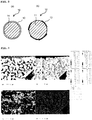
- FIG. 2 is a schematic illustration of exemplar cross-sectional views of magnesium oxide grains comprised in a carrier for a synthesis gas production catalyst according to the present invention.
- a plurality of source magnesium oxide particles may be agglomerated and fused to show a globular form (a) or two source magnesium oxide particles may be put together to show a peanut shell-like form having a center part 51 and two opposite end parts 52 having a diameter greater than the center part 51 (b).
- magnesium oxide grains need to be used for the purpose of the present invention.
- the advantages of the present invention cannot be obtained by using oxide of some other metal such as zirconium oxide(ZrO 2 ) or alumina (Al 2 O 3 ).
- the mode of existence of calcium oxide (CaO) on the surfaces of magnesium oxide (MgO) grains is not subjected to any particular limitations.
- the entire surface or part of the surface of magnesium oxide grain may be covered by a calcium oxide-containing layer.
- the calcium oxide-containing layer formed on the surface of magnesium oxide grain may contain magnesium oxide.
- calcium oxide may be unevenly and locally distributed on the surface of magnesium oxide grain. More specifically, for example, calcium oxide may exist in one or more than one recesses on the surface of magnesium oxide grain.
- FIG. 3 is a schematic illustration of different forms of existence of calcium oxide on the surface of magnesium oxide grain comprised in a carrier for a synthesis gas production catalyst according to the present invention. As shown in FIG.
- a carrier 10 for a synthesis gas production catalyst according to the present invention may be such that a calcium oxide-containing layer 2 is formed on the entire surface of magnesium oxide grain 11 (a) or a calcium oxide layer 13 is formed on part of the surface of magnesium oxide grain 11 (b).
- a calcium oxide layer may locally exist in one or more than one recesses on the surface of magnesium oxide grain.
- a carrier for a synthesis gas production catalyst contains magnesium oxide grains and calcium oxide existing on the surfaces of the magnesium oxide grains.
- the content of calcium oxide existing on the surfaces of the magnesium oxide grains is between 0.005 mass% and 1.5 mass%, preferably between 0.3 mass% and 1.4 mass% in terms of Ca.
- carbon deposition can remarkably be suppressed in reforming operations such as carbon dioxide reforming operations and carbon dioxide/steam reforming operations to make it possible to efficiently produce synthesis gas on a stable basis for a long duration of time.
- the content of calcium oxide existing on the surfaces of the magnesium oxide grains in terms of Ca is less than 0.005 mass%, carbon deposition can easily take place on the surface of the catalyst.
- the content of calcium oxide existing on the surfaces of the magnesium oxide grains in terms of Ca is more than 1.5 mass%, the catalyst shows a poor catalytic activity to make it impossible to obtain the advantages of the present invention.
- the content of calcium oxide existing on the surfaces of the magnesium oxide grains in terms of Ca can be determined by a technique as described below. Namely, the overall content of calcium oxide existing in the magnesium oxide grains in terms of Ca can be determined by dissolving a sample (of the carrier for the synthesis gas catalyst) in aqua regia and observing it by means of an ICP emission spectrometer. At this time, the quantity of Ca quantitatively determined by means of the ICP emission spectrometer can be used as the content of calcium oxide existing on the surfaces of the magnesium oxide grains in terms of Ca by analyzing the distribution of Ca existing in the magnesium oxide grains by EPMA (electron probe microanalysis) and verifying that no Ca exists in the inside of the magnesium oxide grains and substantially all the Ca exists on the surfaces of the magnesium oxide grains also by EPMA.
- EPMA electron probe microanalysis
- calcium oxide exists on the surfaces of the magnesium oxide grains by 0.05 mg-Ca/m 2 -MgO to 150 mg-Ca/m 2 -MgO in terms of Ca.
- the content of calcium oxide existing on the surfaces of the magnesium oxide grains in terms of Ca can be determined by dividing the quantity of calcium oxide existing on the surfaces of the magnesium oxide grains per 1 g of magnesium oxide grains in terms of Ca (unit: mg-Ca/g) by the specific surface area of the carrier for the synthesis gas production catalyst (unit: m 2 /g)
- calcium oxide exists within 10% of the depth from the surface of the carrier 10 for the synthesis gas production catalyst.
- the expression of "within 10% of the depth from the surface of the carrier for the synthesis gas production catalyst” as used herein refers to a region of which depth is within 10% of the maximum depth (the maximum length between the center of gravity and the surface) in each of the magnesium oxide grains comprised in the carrier for the synthesis gas production catalyst, as stated above.
- the above expression refers to a depth from the surface of not more than r 1 /10 toward the center of gravity of the grain.
- the size, or the diameter, of magnesium oxide grain comprised in the carrier for the synthesis gas production catalyst is typically maximally between 0.1 and 10 ⁇ m, although the size is by no means subjected to any particular limitations.
- the thickness of the calcium oxide-containing layer is typically between 5 and 70 nm.
- the carrier for the synthesis gas production catalyst may typically be ring-shaped, multi-hole-shaped, tablet-shaped or pellet-shaped.
- a carrier for a synthesis gas production catalyst according to the present invention can be manufactured, for example, by baking calcium oxide-containing source magnesium oxide powder (particles) at not lower than 1,000oC, causing the source magnesium oxide particles to agglomerate to form magnesium oxide grains and also causing calcium oxide to precipitate on the surfaces of the magnesium oxide grains.
- Calcium oxide-containing source magnesium oxide particles are employed for the above-described manufacturing method.
- the content of calcium oxide contained in the source magnesium oxide particles is between 0.005 mass% and 1.5 mass%, preferably between 0.3 mass% and 1.4 mass%.
- the expression of "calcium oxide-containing source magnesium oxide particles” refers to that the source magnesium oxide particles to be used as source material uniformly contain calcium oxide in the inside thereof within the range between 0.005 mass% and 1.5 mass%.
- highly pure magnesium oxide such as normally commercially available magnesium oxide contains calcium oxide only to a lesser extent so that such magnesium oxide cannot be used as source magnesium oxide particles for the purpose of the present invention.
- calcium oxide-containing source magnesium oxide particles as described above are molded so as to show a desired profile as a carrier for a catalyst, which may typically be ring-shaped, multi-hole-shaped, tablet-shaped or pellet-shaped.
- a lubricant such as carbon may be added to them.
- carbon is preferably added to the source magnesium oxide particles within the range between 1 mass% and 5 mass%.
- a carrier for a synthesis gas production catalyst according to the present invention can be manufactured by baking the calcium oxide-containing source magnesium oxide particles, which may have been molded to show a desired profile if necessary, at not lower than 1,000oC, causing the source magnesium oxide particles to agglomerate to form magnesium oxide grains and also causing calcium oxide to precipitate on the surfaces of the magnesium oxide grains 11.
- source magnesium oxide particles are baked under specific conditions, which will be described hereinafter, the source magnesium oxide particles are caused to agglomerate to form magnesium oxide grains. Additionally, as the source magnesium oxide particles are baked under the specific conditions, the calcium oxide existing in the inside of the source magnesium oxide particles are forced to come out and precipitate on the surfaces of the magnesium oxide grains. Then, the calcium oxide eventually forms a calcium oxide-containing layer on the surfaces of the magnesium oxide grains or comes to locally exist in recesses on the surfaces of the magnesium oxide grains.
- the source magnesium oxide particles contain calcium oxide only to a small extent, calcium oxide precipitates only insufficiently on the surfaces of the grains to make it impossible to obtain the advantage of the present invention of suppressing carbon deposition.
- the baking temperature needs to be not lower than 1,000oC.
- the baking temperature is lower than the above-identified temperature level, calcium oxide existing in the insides of the source magnesium oxide particles would not come out to precipitate on the surfaces of the magnesium oxide grains to make it impossible to obtain the advantages of the present invention.
- the baking temperature is not higher than 1,400oC.
- a carrier for a synthesis gas production catalyst according to the present invention can be manufactured by a method other than the above-described one. More specifically, Ca-added type Mg(OH) 2 particles are obtained by boiling high purity magnesium oxide (for example, MgO containing CaO by not more than 0.01 mass% in terms of Ca and showing a purity of not less than 99.9 mass%) at temperature between 60 and 80oC, while agitating it, and at the same time dropping aqueous solution of Ca(OH) 2 and agitating it. Ca-added type Mg(OH) 2 particles obtained in this way substantially uniformly contain CaO in the inside thereof.
- high purity magnesium oxide for example, MgO containing CaO by not more than 0.01 mass% in terms of Ca and showing a purity of not less than 99.9 mass
- a carrier for a synthesis gas production catalyst according to the present invention can be manufactured by baking the obtained Ca-added type Mg(OH) 2 particles, if necessary adding a lubricant and molding the particles thereto, at temperature not lower than 1,000oC and preferably not higher than 1,400oC so as to cause the Ca-added type Mg(OH) 2 particles to agglomerate and turn into magnesium oxide grains and, at the same time to cause calcium oxide to precipitate on the surfaces of the magnesium oxide grains just as in the instance of using the above-described manufacturing method according to the present invention.
- Neither of the above-described manufacturing methods basically involves any operation of adding calcium oxide to the source magnesium oxide particles.
- the source magnesium oxide particles or the Ca-added type Mg(OH) 2 particles agglomerate or not, if calcium oxide precipitates on the surfaces of the produced magnesium oxide grains or not and when and to what extent such agglomeration and precipitation take place vary depending on the conditions under which the source magnesium oxide particles, the Ca-added type Mg(OH) 2 particles or the molded body thereof is baked.
- the above conditions include the calcium oxide content of the source magnesium oxide particles, the Ca-added type Mo(OH) particles, the baking temperature, the baking atmosphere, the baking time, the type and the rate of addition of the additive or each of the additives including the lubricant and the size and the shape of the molded body to be baked, if such a molded body is used, of the source magnesium oxide particles or the Ca-added type Mg(OH) 2 particles.
- the above-identified baking conditions need to be adjusted in an coordinated manner for the purpose of forming magnesium oxide grains by causing the source magnesium oxide particles or the Ca-added type Mg(OH) 2 to agglomerate and also causing calcium oxide to precipitate on the surfaces of the magnesium oxide grains to form calcium oxide-containing layers on the surfaces of the magnesium oxide grains.
- a synthesis gas production catalyst according to the present invention is at least either of the metals of ruthenium (Ru) and Rhodium (Rh) that is carried by a carrier for a synthesis gas production catalyst according to the present invention as defined above.
- the metal to be carried by a carrier needs to be at least either Ru or Rh.
- the advantages of the present invention cannot be obtained by causing any other metal such as Ni, Ir or Os to be carried by a carrier.
- the rate at which either Ru or Rh is carried by a carrier for the purpose of the present invention is preferably between 200 mass ppm and 2,000 mass ppm relative to the carrier for a synthesis gas production catalyst in terms of metal.
- both Ru and Rh are to be carried by a carrier, they are preferably carried in combination at a rate between 200 mass ppm and 2,000 mass ppm.
- the rate at which Ru or Rh is carried by a carrier can be determined by means of an ICP emission spectrometer. More specifically, it can be quantified by dissolving a sample of the catalyst in aqua regia and irradiating it with light of a predetermined measurement wavelength.
- the specific surface area of a synthesis gas production catalyst according to the present invention is between 0.1 m 2 /g and 1.0 m 2 /g.
- the specific surface area refers to the BET specific surface area determined by means of the BET adsorption isotherm on the basis of the rate of nitrogen gas adsorption.
- a specific surface area can be determined by means of a specific surface area measurement device (e.g., "AUTOSORB-1": tradename, available from Yuasa Ionics) for multi-point measurement using liquid nitrogen.
- Ru and/or Rh to be carried by a synthesis gas production catalyst preferably exist within 10% of the depth from the surface of the synthesis gas production catalyst.
- the expression of "within 10% of the depth from the surface of the synthesis gas production catalyst” when the largest distance between the center of gravity and the surface of the synthesis gas production catalyst is expressed as radius r 2 , the above expression refers to a position separated from the surface by not more than r 2 /10 toward the center of gravity as in the above-described case of a carrier for a synthesis gas production catalyst.
- Ru and/or Rh preferably exist in the vicinity of calcium oxide on the surfaces of the magnesium oxide grains.
- a metal-containing layer containing at least either Ru or Rh may cover the entire surface or part of the surface of magnesium oxide grain.
- metal particles containing Ru and/or Rh may simply exist on the surface of magnesium oxide grain.
- Ru and/or Rh may be unevenly and locally distributed on the surface of magnesium oxide grain.
- Ru and/or Rh may exist in one or more than one recesses on the surface of a magnesium oxide grain or Ru and/or Rh may exist in the form of a layer or grains so as to cover at least part of the calcium oxide layer.
- Ru and/or Rh existing in the form of a layer or grains and calcium oxide existing in the form of a layer or grains may be located side by side.
- a metal-containing layer may be formed on or under a calcium oxide layer or, alternatively, a metal layer and a calcium oxide layer may be located side by side.
- the size, or the diameter, of magnesium oxide grains comprised in a synthesis gas production catalyst is typically maximally between 1 and 10 ⁇ m.
- the thickness of a calcium oxide-containing layer is typically between 5 and 70 ⁇ m and the thickness of a metal-containing layer is also typically between 5 and 70 ⁇ m.
- Methods that can be used for causing a carrier for a synthesis gas production catalyst to carry at least either of the metals of Ru and Rh include a method of using aqueous solution of at least either of the metals of Ru and Rh and spraying the aqueous solution onto a carrier for a synthesis gas production catalyst.
- Aqueous solution of at least either of the metals of Ru and Rh can be obtained by dissolving a source metal material such as nitrate, chloride or some other inorganic salt of Ru and/or Rh or acetate or some other organic salt of Ru and/or Rh into water.
- the amount of such aqueous solution to be sprayed is preferably 1.0 to 1.3 times of the mass of water that a carrier for a synthesis gas production catalyst can absorb.
- the amount of water that a carrier for a synthesis gas production catalyst can absorb can be determined by an incipient-wetness method. With such a method, pure water is dropped onto a carrier for a synthesis gas production catalyst by a small quantity at a time by means of a micropipette or a burette and the amount of pure water dropped until the catalyst surface becomes wet is measured.
- At least either of the metals of Ru and Rh can be made to be carried by a carrier for a synthesis gas production catalyst according to the present invention by means of an impregnation method of adding a salt of the metal or aqueous solution of the salt to a dispersion obtained by dispersing a carrier for a synthesis gas production catalyst in water and mixing them.
- a synthesis gas production catalyst can be obtained by drying and baking a carrier for a synthesis gas production catalyst that is made to carry Ru and/or Rh.
- the drying and baking conditions are not subjected to any particular limitations. However, the drying temperature is typically between 50 and 150oC and the drying time is typically between 1 and 3 hours, while the baking temperature is typically between 300 and 500oC and the baking time is typically between 1 and 5 hours.
- a synthesis gas production catalyst, or a carrier for a synthesis gas production catalyst after having been made to carry Ru and/or Rh thereon and then dried and baked, is subsequently brought into contact with hydrogen and nitrogen at temperature not lower than 350oC with a hydrogen to nitrogen molar ratio (hydrogen/nitrogen) between 1 and 10.
- the catalyst may be brought into contact with hydrogen and steam at temperature not lower than 350oC with a hydrogen to steam molar ratio (hydrogen/steam) between 1 and 10.
- a reduction treatment dechlorination treatment
- synthesis gas containing carbon monoxide and hydrogen is produced from source gas containing methane-containing light hydrocarbons and carbon dioxide (along with steam) in the presence of a synthesis gas production catalyst according to the present invention as defined above.
- a synthesis gas production catalyst according to the present invention can remarkably suppress the rate at which carbon deposits. Therefore, it is now possible to efficiently conduct carbon dioxide reforming operations and carbon dioxide/steam reforming operations on a stable basis for a long duration of time. For instance, the initial efficiency of such a reforming operation can be maintained after conducting a carbon dioxide reforming operation or a carbon dioxide/steam reforming operation for not less than 700 hours.
- Light hydrocarbons that can be used for the purpose of the present invention are hydrocarbons having one to six carbon atoms in a molecule such as methane and ethane.
- natural gas containing methane as principal component can suitably be used for the purpose of the present invention.
- the reaction for producing synthesis gas containing carbon monoxide and hydrogen from source gas containing methane-containing light hydrocarbons and carbon dioxide is typically expressed by the chemical formula (1) shown below.
- the chemical formula (1) shown below typically represents an instance where methane is used as light hydrocarbon. CH 4 + CO 2 ⁇ 2H 2 + 2CO (1)
- a carbon dioxide reforming operation can be conducted by means of any of various contact systems including fixed bed systems, fluidized bed systems, suspension type systems and moving bed systems.
- synthesis gas containing hydrogen and carbon monoxide can be produced by driving source gas containing methane-containing light hydrocarbons and carbon dioxide to pass through a reactor installed in a heating furnace and having a catalyst layer filled with a catalyst.
- reaction conditions are not subjected to any particular limitations, typically the use of gas temperature between 700 and 900oC at the catalyst layer outlet, gas pressure between 1.5 MPaG and 3.0 MPaG at the catalyst layer outlet and a gas hourly space velocity GHSV between 500/hour and 5,000/hour is preferable.
- synthesis gas can be produced with the above-identified CO 2 /C range without large carbon deposition so that carbon dioxide reforming operations can efficiently be conducted on a stable basis for a long duration of time.
- source gas containing steam in addition to methane-containing light hydrocarbons and carbon dioxide may be used for the purpose of the present invention.
- carbon dioxide/steam reforming operations may be conducted for the purpose of the present invention.
- synthesis gas can be produced by way of both a carbon dioxide reforming reaction and a steam reforming reaction.
- the reaction that takes place in a steam reforming operation is typically expressed by the chemical formula (2) shown below.
- the chemical formula (2) shown below typically represents an instance where methane is used as light hydrocarbon.
- Carbon dioxide reforming and steam reforming differ from each other particularly in terms of the H 2 to CO ratio in the obtained synthesis gas. Therefore, it is possible to obtain synthesis gas that contains H 2 and Co at a desired ratio by adjusting the carbon dioxide to steam ratio.
- source gas containing methane-containing light hydrocarbons, carbon dioxide and steam it is desirable to drive source gas to flow in such a way that the abundance ratio of steam to light hydrocarbons H 2 O/C (where H 2 O represents the number of moles of steam and C represents the number of moles of carbon atoms derived from hydrocarbons) in the source gas is found within the range between 0.1 and 3.0.
- H 2 O represents the number of moles of steam
- C represents the number of moles of carbon atoms derived from hydrocarbons
- an inactivated synthesis gas production catalyst is to be employed unlike the above-described activated synthesis gas production catalyst, such a synthesis gas production catalyst is brought to contact with hydrogen and nitrogen under conditions including a hydrogen to nitrogen molar ratio (hydrogen/nitrogen) between 1 and 10 and temperature not lower than 350oC or such a synthesis gas production catalyst is brought to contact with hydrogen and steam under conditions including a hydrogen to steam molar ratio (hydrogen/steam) between 1 and 10 and temperature not lower than 350oC and subsequently the synthesis gas production catalyst is brought to contact with source gas.
- hydrogen to nitrogen molar ratio hydrogen/nitrogen
- steam hydrogen to steam molar ratio
- the obtained catalyst carrier was then analyzed by means of ICP emission analysis (to be also referred to simply as "ICP" hereinafter) to find that the catalyst carrier contained CaO by 0.3 wt% in terms of Ca.
- ICP ICP emission analysis
- the MgO grains comprised in the obtained catalyst carrier were remarkably larger than the source magnesium oxide particles. Therefore, it may be safe to say that the source MgO particles agglomerated to form MgO grains and the CaO contained in the source magnesium oxide particles precipitated on the surfaces of the MgO grains.
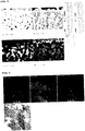
- Example 4 is a schematic illustration of some of the results of the EPMA analysis of cross sections of the carrier for the synthesis gas production catalyst in Example 1.
- Table 1 shows the results of quantification of each element obtained by an EPMA analysis conducted on the obtained catalyst carrier as expressed in terms of mol%. Note that analysis points P1 through P10 are the respective points indicated by arrows in FIG. 4 .
- the obtained catalyst was in the form of spherical grains and peanut shell-like grains. Additionally, each catalyst carrier grains was such that part of the surface of the MgO grain was covered by a layer that contained CaO (CaO-containing layer) and CaO also existed in recesses on the surfaces of MgO grains. Additionally, the CaO existed within 10% of the depth from the catalyst surface.
- the quantity of calcium oxide on the surface of an MgO grain per unit area of the surface was determined in terms of Ca (mg-Ca/m 2 -MgO) (to be also referred to as "the abundance of CaO on the surface of an MgO grain" hereinafter) to find that it was 30 mg-Ca/m 2 -MgO in terms of Ca.
- aqueous solution of ruthenium nitrosyl nitrate containing Ru by 0.5 wt% was sprayed onto the obtained catalyst carrier at a rate of 0.15 cc per 1.0 g of the catalyst carrier (1.0 times of the water absorption of the catalyst carrier) to obtain a Ru-carrying catalyst carrier.
- the obtained Ru-carrying catalyst carrier was dried in an oven arranged in the open air at 120oC for 2.5 hours and subsequently baked in an electric furnace arranged in the open air at 400oC for 2.0 hours to obtain a catalyst final product.
- the obtained catalyst contained Ru at a rate of 750 wtppm relative to the catalyst and its BET specific surface area was 0.10 m 2 /g.
- the obtained catalyst was subjected to an EPMA analysis.
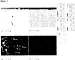
- FIG. 5 shows some of the results of the EPMA analysis conducted on the catalyst.
- Table 2 shows the result of quantification of each element obtained by the EPMA analysis conducted on the obtained catalyst as expressed in terms of mol%. Note that the analysis points P1 through P11 are the respective points indicated by arrows in FIG. 5 .
- Ru was carried on the surfaces of the catalyst grains of the obtained catalyst. Ru existed within 10% of the depth from the catalyst surface. The fact that the positions of Ru substantially agreed with the positions of Ca evidenced that CaO existed in the vicinity of Ru. Note that all the Ru and CaO contained in the catalyst carrier existed on the surfaces of MgO grains.
- Ca was contained in the center part of peanut shell-like grain only by a very small amount (see analysis points P3 and P10) and Ca was mostly contained in the opposite end parts thereof (see analysis points P1, P2, P4 through P9 and P11).
- FIG. 6 is a schematic illustration of some of the results of the element mapping by EDX of the synthesis gas production catalyst.
- the upper row shows Ca, Mg and Ru from left.
- the lower one is a TEM photograph.
- MgO powder that contained CaO in the inside by 0.3 wt% in terms of Ca and showed a purity of not less than 98.7 wt% was mixed with 3.0 wt% carbon, which operated as lubricant relative to the MgO powder, and the mixture was used to form a cylindrical pellet having a diameter of 1/4 inches.
- the formed pellet was baked at 1,180oC in air for 3 hours to obtain the catalyst carrier of this example.
- the obtained catalyst carrier was then analyzed by means of ICP to find that the catalyst carrier contained CaO by 0.3 wt% in terms of Ca.
- the catalyst carrier contained CaO by 0.3 wt% in terms of Ca.
- the MgO grains comprised in the obtained catalyst carrier were remarkably larger than the source magnesium oxide particles. Therefore, it may be safe to say that the source MgO particles agglomerated to form MgO grains and the CaO contained in the source MgO particles precipitated on the surfaces of the MgO grains.
- the obtained catalyst carrier was granular as in Example 1 and part of MgO grain was covered by a CaO-containing layer while CaO also existed in recesses on the surfaces of MgO grains. Additionally, CaO was found within 10% of the depth from the surface of the catalyst carrier. The abundance of CaO on the surface of an MgO grain was determined to find that it was 30 mg-Ca/m 2 -MgO in terms of Ca. Ca was contained in the center part of peanut shell-like grain only by a very small amount and Ca was mostly contained in the opposite end parts thereof.
- RuCl 3 ruthenium chloride hydrate
- the obtained Ru-carrying catalyst carrier was dried in an oven arranged in the open air at 120oC for 2.5 hours and subsequently baked in an electric furnace arranged in the open air at 400oC for 2.0 hours to obtain a catalyst final product.
- the obtained catalyst contained Ru at a rate of 900 wtppm relative to the catalyst and its BET specific surface area was 0.10 m 2 /g.
- the obtained catalyst was subjected to an EPMA analysis as in Example 1 to find that Ru was carried on the surfaces of the catalyst grains. Ru existed within 10% of the depth from the catalyst surface. Additionally, CaO existed in the vicinity of Ru.
- Example 2 50 cc of the catalyst prepared in Example 2 was filled in a reactor similar to the one used in Example 1 and a CO 2 reforming test of methane was conducted.
- the catalyst was vertically divided into 4 pieces and drawn out to find that the carbon/catalyst ratios of the pieces were sequentially from above 0.25 wt%, 0.1 wt%, 0.1 wt% and 0.04 wt%. Additionally, the catalyst that had been treated under the above-described treatment conditions of Reaction Example 2 was analyzed as in the instance of Example 1 to confirm that granular Ru existed on the catalyst surface.
- MgO powder that contained CaO in the inside by 0.3 wt% in terms of Ca and showed a purity of not less than 98.7 wt% was mixed with 3.0 wt% carbon, which operated as lubricant relative to the MgO powder, and the mixture was used to form a cylindrical pellet having a diameter of 1/4 inches.
- the formed pellet was baked at 1,180oC in air for 3 hours to obtain the catalyst carrier of this example.
- the obtained catalyst carrier was then analyzed by means of ICP to find that the catalyst carrier contained CaO by 0.3 wt% in terms of Ca.
- the catalyst carrier contained CaO by 0.3 wt% in terms of Ca.
- the MgO grains comprised in the obtained catalyst carrier were remarkably larger than the source magnesium oxide particles. Therefore, it may be safe to say that the source MgO particles agglomerated to form MgO grains and the CaO contained in the source MgO grains precipitated on the surfaces of the MgO grains.
- the obtained catalyst carrier was granular as in Example 1 and part of the surface of MgO grain was covered by a CaO-containing layer while CaO also existed in recesses on the surfaces of MgO grains. Additionally, CaO was found within 10% of the depth from the surface of the catalyst carrier. The abundance of CaO on the surface of an MgO grain was determined to find that it was 30 mg-Ca/m 2 -MgO in terms of Ca. Ca was contained in the center part of peanut shell-like grain only by a very small amount and Ca was mostly contained in the opposite end parts thereof.
- aqueous solution of ruthenium nitrate containing Ru by 0.17 wt% was sprayed onto the obtained catalyst carrier at a rate of 0.18 cc per 1.0 g of the catalyst carrier (1.2 times of the water absorption of the catalyst carrier) to obtain a Ru-carrying catalyst carrier.
- the obtained Ru-carrying catalyst carrier was dried in an oven arranged in the open air at 120oC for 2.5 hours and subsequently baked in an electric furnace arranged in the open air at 400oC for 2.0 hours to obtain a catalyst final product.
- the obtained catalyst contained Ru at a rate of 300 wtppm relative to the catalyst and its BET specific surface area was 0.10 m 2 /g.
- the obtained catalyst was subjected to an EPMA analysis as in Example 1 to find that Ru was carried on the surfaces of the catalyst grains. Ru existed within 10% of the depth from the catalyst surface. Additionally, CaO existed in the vicinity of Ru.
- Example 3 50 cc of the catalyst prepared in Example 3 was filled in a reactor similar to the one used in Example 1 and a H 2 O/CO 2 reforming test of methane was conducted.
- the catalyst was vertically divided into 4 pieces and drawn out to find that the carbon/catalyst ratios of the pieces were sequentially from above 0.2 wt%, 0.05 wt%, 0.03 wt% and 0.02 wt%. Additionally, the catalyst that had been treated under the above-described treatment conditions of Reaction Example 3 was analyzed as in Example 1 to confirm that granular Ru existed on the catalyst surface.
- MgO powder that contained CaO in the inside by 0.3 wt% in terms of Ca and showed a purity of not less than 98.7 wt% was mixed with 3.0 wt% carbon, which operated as lubricant relative to the MgO powder, and the mixture was used to form a cylindrical pellet having a diameter of 1/4 inches.
- the formed pellet was baked at 1,150oC in air for 3 hours to obtain the catalyst carrier of this example.
- the obtained catalyst carrier was then analyzed by means of ICP to find that the catalyst carrier contained CaO by 0.3 wt% in terms of Ca.
- the catalyst carrier contained CaO by 0.3 wt% in terms of Ca.
- the MgO grains comprised in the obtained catalyst carrier were remarkably larger than the source magnesium oxide particles. Therefore, it may be safe to say that the source MgO particles agglomerated to form MgO grains and the CaO contained in the source MgO particles precipitated on the surfaces of the MgO grains.
- the obtained catalyst carrier was granular as in Example 1 and part of the surface of MgO grain was covered by a CaO-containing layer while CaO also existed in recesses on the surfaces of MgO grains. Additionally, CaO was found within 10% of the depth from the surface of the catalyst carrier. The abundance of CaO on the surface of MgO grain was determined to find that it was 25 mg-Ca/m 2 -MgO in terms of Ca. Ca was contained in the center part of peanut shell-like grain only by a very small amount and Ca was mostly contained in the opposite end parts thereof.
- aqueous solution of rhodium acetate containing Ru (Rh(CH 3 COO) 3 ) by 0.3 wt% was sprayed onto the obtained catalyst carrier at a rate of 0.15 cc per 1.0 g of the catalyst carrier (1.0 times of the water absorption of the catalyst carrier) to obtain a Ru-carrying catalyst carrier.
- Rh-carrying catalyst carrier was dried in an oven arranged in the open air at 120oC for 2.5 hours and subsequently baked in an electric furnace arranged in the open air at 650oC for 2.0 hours to obtain a catalyst final product.
- the obtained catalyst contained Rh at a rate of 450 wtppm relative to the catalyst and its BET specific surface area was 0.12 m 2 /g.
- the obtained catalyst was subjected to an EPMA analysis as in Example 1 to find that Ru was carried on the surfaces of the catalyst grains. Ru existed within 10% of the depth from the catalyst surface. Additionally, CaO existed in the vicinity of Rh.
- Example 4 50 cc of the catalyst prepared in Example 4 was filled in a reactor similar to the one used in Example 1 and a CO 2 reforming test of methane was conducted.
- the catalyst was vertically divided into 4 pieces and drawn out to find that the carbon contents of the pieces were sequentially from above 0.15 wt%, 0.1 wt%, 0.05 wt% and 0.03 wt%.
- the catalyst that had been treated under the above-described treatment conditions of Reaction Example 4 was analyzed as in Example 1 to confirm that granular Ru existed on the catalyst surface.
- MgO powder that contained CaO in the inside by 0.3 wt% in terms of Ca and showed a purity of not less than 98.7 wt% was mixed with 3.0 wt% carbon, which operated as lubricant relative to the MgO powder, and the mixture was used to form a cylindrical pellet having a diameter of 1/4 inches.
- the formed pellet was baked at 1,200oC in air for 3 hours to obtain the catalyst carrier of this example.
- the obtained catalyst carrier was then analyzed by means of ICP to find that the catalyst carrier contained CaO by 0.3 wt% in terms of Ca.
- the catalyst carrier contained CaO by 0.3 wt% in terms of Ca.
- the MgO grains comprised in the obtained catalyst carrier were remarkably larger than the source magnesium oxide particles. Therefore, it may be safe to say that the source MgO particles agglomerated to form MgO grains and the CaO contained in the source MgO particles precipitated on the surfaces of the MgO grains.
- the obtained Ru-carrying catalyst carrier was dried in an oven arranged in the open air at 120oC for 2.5 hours and subsequently baked in an electric furnace arranged in the open air at 400oC for 2.0 hours to obtain a catalyst final product.
- the obtained catalyst contained Ru at a rate of 1,100 wtppm relative to the catalyst and its BET specific surface area was 0.08 m 2 /g.
- the obtained catalyst was subjected to an EPMA analysis as in Example 1 to find that Ru was carried on the surfaces of the catalyst grains. Ru existed within 10% of the depth from the catalyst surface. Additionally, CaO existed in the vicinity of Ru.
- Example 5 50 cc of the catalyst prepared in Example 5 was filled in a reactor similar to the one used in Example 1 and a CO 2 reforming test of methane was conducted.
- the catalyst was vertically divided into 4 pieces and drawn out to find that the carbon contents of the pieces were sequentially from above 0.15 wt%, 0.04 wt%, 0.03 wt% and 0.01 wt%.
- the catalyst that had been treated under the above-described treatment conditions of Reaction Example 5 was analyzed as in the instance of Example 1 to confirm that granular Ru existed on the catalyst surface.
- MgO powder that contained CaO in the inside by 0.3 wt% in terms of Ca and showed a purity of not less than 98.7 wt% was mixed with 3.0 wt% carbon, which operated as lubricant relative to the MgO powder, and the mixture was used to form a cylindrical pellet having a diameter of 1/4 inches.
- the formed pellet was baked at 1,130oC in air for 3 hours to obtain the catalyst carrier of this example.
- the obtained catalyst carrier was then analyzed by means of ICP to find that the catalyst carrier contained CaO by 0.3 wt% in terms of Ca.
- the catalyst carrier contained CaO by 0.3 wt% in terms of Ca.
- the MgO grains comprised in the obtained catalyst carrier were remarkably larger than the source magnesium oxide particles. Therefore, it may be safe to say that the source MgO particles agglomerated to form MgO grains and the CaO contained in the source MgO particles precipitated on the surfaces of the MgO grains.
- the obtained catalyst carrier was granular as in Example 1 and part of the surface of MgO grain was covered by a CaO-containing layer while CaO also existed in recesses on the surfaces of MgO grains. Additionally, CaO was found within 10% of the depth from the surface of the catalyst carrier. The abundance of CaO on the surface of MgO grain was determined to find that it was 20 mg-Ca/m 2 -MgO in terms of Ca. Ca was contained in the center part of peanut shell-like grain only by a very small amount and Ca was mostly contained in the opposite end parts thereof.
- aqueous solution of ruthenium nitrate containing Ru by 0.6 wt% was sprayed onto the obtained catalyst carrier by 0.18 g (1.2 times of the water absorption of the catalyst carrier) to obtain a Ru-carrying catalyst carrier.
- the obtained Ru-carrying catalyst carrier was dried in an oven arranged in the open air at 120oC for 2.5 hours and subsequently baked in an electric furnace arranged in the open air at 400oC for 2.0 hours to obtain a catalyst final product.
- the obtained catalyst contained Ru at a rate of 780 wtppm relative to the catalyst and its BET specific surface area was 0.15 m 2 /g.
- the obtained catalyst was subjected to an EPMA analysis as in Example 1 to find that Ru was carried on the surfaces of the catalyst grains. Ru existed within 10% of the depth from the catalyst surface. Additionally, CaO existed in the vicinity of Ru.
- Example 6 50 cc of the catalyst prepared in Example 6 was filled in a reactor similar to the one used in Example 1 and an H 2 O/CO 2 reforming test of methane was conducted.
- the catalyst was vertically divided into 4 pieces and drawn out to find that the carbon contents of the pieces were sequentially from above 0.11 wt%, 0.05 wt%, 0.03 wt% and 0.01 wt%. Additionally, the catalyst that had been treated under the above-described treatment conditions of Reaction Example 6 was analyzed as in the instance of Example 1 to confirm that granular Ru existed on the catalyst surface.
- Ca-added type Mg(OH) 2 particles were obtained by simultaneously dropping aqueous solution of Ca(OH) 2 and agitating the mixture. Then, the added type product was mixed with 3.0 wt% carbon, which operated as lubricant relative to the added type product, and a cylindrical pellet having a diameter of 1/4 inches was formed from the mixture. The formed pellet was additionally baked at 1,180oC in the air for 3 hours to obtain a catalyst carrier.
- the obtained catalyst carrier was then analyzed by means of ICP as in Example 1 to find that the catalyst carrier contained CaO by 0.5 wt% in terms of Ca.
- the catalyst carrier contained CaO by 0.5 wt% in terms of Ca.
- the MgO grains comprised in the obtained catalyst carrier were remarkably larger than the Ca-added type Mg(OH) 2 particles. Therefore, it may be safe to say that the Ca-added type Mg(OH) 2 particles agglomerated to form MgO grains and the CaO contained in the Ca-added type Mg(OH) 2 particles precipitated on the surfaces of the MgO grains.
- the obtained catalyst carrier was granular as in Example 1 and part of the surface of MgO grain was covered by a CaO-containing layer while CaO also existed in recesses on the surfaces of MgO grains. Additionally, CaO was found within 10% of the depth from the surface of the catalyst carrier. The abundance of CaO on the surface of MgO grain was determined to find that it was 50 mg-Ca/m 2 -MgO in terms of Ca. Ca was contained in the center part of peanut shell-like grain only by a very small amount and Ca was mostly contained in the opposite end parts thereof.
- aqueous solution of ruthenium nitrate that contained Ru by 0.8 wt% was sprayed onto the obtained catalyst carrier at a rate of 0.15 cc per 1.0 g of the catalyst carrier (1.0 times of the water absorption of the catalyst carrier) to obtain a Ru-carrying catalyst carrier.
- the obtained Ru-carrying catalyst carrier was dried in an oven arranged in the open air at 120oC for 2.5 hours and subsequently baked in an electric furnace arranged in the open air at 400oC for 2.0 hours to obtain a catalyst final product.
- the obtained catalyst contained Ru at a rate of 1,000 wtppm relative to the catalyst and its BET specific surface area was 0.10 m 2 /g.
- the obtained catalyst was subjected to an EPMA analysis as in Example 1 to find that Ru was carried on the surfaces of the catalyst grains. Ru existed within 10% of the depth from the catalyst surface. Additionally, CaO existed in the vicinity of Ru.
- Example 7 50 cc of the catalyst prepared in Example 7 was filled in a reactor similar to the one used in Example 1 and an H 2 O/CO 2 reforming test of methane was conducted.
- the catalyst was vertically divided into 4 pieces and drawn out to find that the carbon contents of the pieces were sequentially from above 0.15 wt%, 0.08 wt%, 0.05 wt% and 0.01 wt%. Additionally, the catalyst that had been treated under the above-described treatment conditions of Reaction Example 7 was analyzed as in the instance of Example 1 to confirm that granular Ru existed on the catalyst surface.
- Ca-added type Mg(OH) 2 particles were obtained by simultaneously dropping aqueous solution of Ca(OH) 2 and agitating the mixture. Then, the added type product was mixed with 3.0 wt% carbon, which operated as lubricant relative to the added type product, and a pellet having a diameter of 1/4 inches was formed from the mixture. The formed pellet was additionally baked at 1,180oC in the air for 3 hours to obtain a catalyst carrier.
- the obtained catalyst carrier was then analyzed by means of ICP as in Example 1 to find that the catalyst carrier contained CaO by 1.4 wt% in terms of Ca.
- the catalyst carrier contained CaO by 1.4 wt% in terms of Ca.
- the MgO grains comprised in the obtained catalyst carrier were remarkably larger than the Ca-added type Mg(OH) 2 particles. Therefore, it may be safe to say that the Ca-added type Mg(OH) 2 particles agglomerated to form MgO grains and the CaO contained in the Ca-added type Mg(OH) 2 particles precipitated on the surfaces of the MgO grains.
- the obtained catalyst carrier was granular as in Example 1 and part of the surface of MgO grain was covered by a CaO-containing layer while CaO also existed in recesses on the surfaces of MgO grains. Additionally, CaO was found within 10% of the depth from the surface of the catalyst carrier. The abundance of CaO on the surface of MgO grain was determined to find that it was 140 mg-Ca/m 2 -MgO in terms of Ca. Ca was contained in the center part of peanut shell-like grain only by a very small amount and Ca was mostly contained in the opposite end parts thereof.
- aqueous solution of ruthenium nitrate that contained Ru by 0.7 wt% was sprayed onto the obtained catalyst carrier at a rate of 0.15 cc per 1.0 g of the catalyst carrier (1.0 times of the water absorption of the catalyst carrier) to obtain a Ru-carrying catalyst carrier.
- the obtained Ru-carrying catalyst carrier was dried in an oven arranged in the open air at 120oC for 2.5 hours and subsequently baked in an electric furnace arranged in the open air at 400oC for 2.0 hours to obtain a catalyst final product.
- the obtained catalyst contained Ru at a rate of 910 wtppm relative to the catalyst and its BET specific surface area was 0.10 m 2 /g.
- the obtained catalyst was subjected to an EPMA analysis as in Example 1 to find that Ru was carried on the surfaces of the catalyst grains. Ru existed within 10% of the depth from the catalyst surface. Additionally, CaO existed in the vicinity of Ru.
- Example 8 50 cc of the catalyst prepared in Example 8 was filled in a reactor similar to the one used in Example 1 and an H 2 O/CO 2 reforming test of methane was conducted.
- the catalyst was vertically divided into 4 pieces and drawn out to find that the carbon contents of the pieces were sequentially from above 0.21 wt%, 0.15 wt%, 0.08 wt% and 0.01 wt%. Additionally, the catalyst that had been treated under the above-described treatment conditions of Reaction Example 8 was analyzed as in the instance of Example 1 to confirm that granular Ru existed on the catalyst surface.
- MgO powder that contained CaO in the inside by 0.3 wt% in terms of Ca and showed a purity of not less than 98.7 wt% was mixed with 3.0 wt% carbon, which operated as lubricant relative to the MgO powder, and the mixture was used to form a cylindrical pellet having a diameter of 1/4 inches.
- the formed pellet was baked at 1,150 9 C in air for 3 hours to obtain the catalyst carrier of this example.
- the obtained catalyst carrier was then analyzed by means of ICP as in Example 1 to find that the catalyst carrier contained CaO by 0.3 wt% in terms of Ca.
- the catalyst carrier contained CaO by 0.3 wt% in terms of Ca.
- the MgO grains comprised in the obtained catalyst carrier were remarkably larger than the source magnesium oxide grains. Therefore, it may be safe to say that the source MgO grains agglomerated to form MgO grains and the CaO contained in the source MgO grains precipitated on the surfaces of the MgO grains.
- the obtained catalyst carrier was granular as in Example 1 and part of the surface of MgO grain was covered by a CaO-containing layer while CaO also existed in recesses on the surfaces of MgO grains. Additionally, CaO was found within 10% of the depth from the surface of the catalyst carrier. The abundance of CaO on the surface of MgO grain was determined to find that it was 25 mg-Ca/m 2 -MgO in terms of Ca. Ca was contained in the center part of peanut shell-like grain only by a very small amount and Ca was mostly contained in the opposite end parts thereof.
- aqueous solution of rhodium acetate containing Rh by 0.81 wt% was sprayed onto the obtained catalyst carrier by 0.17 cc (1.1 times of the water absorption of the catalyst carrier) relative to 1.0 g of the catalyst carrier to obtain a Rh-carrying catalyst carrier.
- Rh-carrying catalyst carrier was dried in an oven arranged in the open air at 120oC for 2.5 hours and subsequently baked in an electric furnace arranged in the open air at 650oC for 2.0 hours to obtain a catalyst final product.
- the obtained catalyst contained Rh at a rate of 1,350 wtppm relative to the catalyst and its BET specific surface area was 0.12 m 2 /g.
- the obtained catalyst was subjected to an EPMA analysis as in Example 1 to find that Rh was carried on the surfaces of the catalyst grains. Rh existed within 10% of the depth from the catalyst surface. Additionally, CaO existed in the vicinity of Rh.
- Example 9 50 cc of the catalyst prepared in Example 9 was filled in a reactor similar to the one used in Example 1 and an H 2 O/CO 2 reforming test of methane was conducted.
- the catalyst was vertically divided into 4 pieces and drawn out to find that the carbon contents of the pieces were sequentially from above 0.15 wt%, 0.07 wt%, 0.05 wt% and 0.01 wt%. Additionally, the catalyst that had been treated under the above-described treatment conditions of Reaction Example 9 was analyzed as in the instance of Example 1 to confirm that granular Rh existed on the catalyst surface.
- Ca-added type Mg(OH) 2 particles were obtained by simultaneously dropping aqueous solution of Ca(OH) 2 and agitating the mixture. Then, the added type product was mixed with 3.0 wt% carbon, which operated as lubricant relative to the added type product, and a pellet having a diameter of 1/4 inches was formed from the mixture. The formed pellet was additionally baked at 1,180oC for 3 hours in the air to obtain a catalyst carrier.
- the obtained catalyst carrier was then analyzed by means of ICP as in Example 1 to find that the catalyst carrier contained CaO by 0.01 wt% in terms of Ca.
- the catalyst carrier contained CaO by 0.01 wt% in terms of Ca.
- the MgO grains comprised in the obtained catalyst carrier were remarkably larger than the Ca-added type Mg(OH) 2 particles. Therefore, it may be safe to say that the Ca-added type Mg(OH) 2 particles agglomerated to form MgO grains and the CaO contained in the Ca-added type Mg(OH) 2 particles precipitated on the surfaces of the MgO grains.
- the obtained catalyst carrier was granular as in Example 1 and part of the surface of MgO grain was covered by a CaO-containing layer while CaO also existed in recesses on the surfaces of MgO grains. Additionally, CaO was found within 10% of the depth from the surface of the catalyst carrier. The abundance of CaO on the surface of MgO grain was determined to find that it was 1 mg-Ca/m 2 -MgO in terms of Ca. Ca was contained in the center part of peanut shell-like grain only by a very small amount and Ca was mostly contained in the opposite end parts thereof.
- aqueous solution of ruthenium nitrate that contained Ru by 0.6 wt% was sprayed onto the obtained catalyst carrier at a rate of 0.15 cc per 1.0 g of the catalyst carrier (1.0 times of the water absorption of the catalyst carrier) to obtain a Ru-carrying catalyst carrier.
- the obtained Ru-carrying catalyst carrier was dried in an oven arranged in the open air at 120oC for 2.5 hours and subsequently baked in an electric furnace arranged in the open air at 400oC for 2.0 hours to obtain a catalyst final product.
- the obtained catalyst contained Ru at a rate of 780 wtppm relative to the catalyst and its BET specific surface area was 0.10 m 2 /g.
- the obtained catalyst was subjected to an EPMA analysis as in Example 1 to find that Ru was carried on the surfaces of the catalyst grains. Ru existed within 10% of the depth from the catalyst surface. Additionally, CaO existed in the vicinity of Ru.
- Example 10 50 cc of the catalyst prepared in Example 10 was filled in a reactor similar to the one used in Example 1 and an H 2 O/CO 2 reforming test of methane was conducted.
- the catalyst was vertically divided into 4 pieces and drawn out to find that the carbon contents of the pieces were sequentially from above 0.28 wt%, 0.17 wt%, 0.09 wt% and 0.01 wt%. Additionally, the catalyst that had been treated under the above-described treatment conditions of Reaction Example 10 was analyzed as in the instance of Example 1 to confirm that granular Ru existed on the catalyst surface.
- MgO powder that contained CaO in the inside by 0.3 wt% in terms of Ca and showed a purity of not less than 98.7 wt% was mixed with 3.0 wt% carbon, which operated as lubricant relative to the MgO powder, and the mixture was used to form a cylindrical pellet having a diameter of 1/4 inches.
- the formed pellet was baked at 1,110oC in air for 3 hours to obtain the catalyst carrier of this comparative example.
- the obtained catalyst carrier was then analyzed by means of ICP as in Example 1 to find that the catalyst carrier contained CaO by 0.3wt% in terms of Ca.
- the catalyst carrier contained CaO by 0.3wt% in terms of Ca.
- the MgO grains comprised in the obtained catalyst carrier were remarkably larger than the source magnesium oxide particles. Therefore, it may be safe to say that the source MgO particles agglomerated to form MgO grains and the CaO contained in the source MgO particles precipitated on the surfaces of the MgO grains.
- the obtained catalyst carrier was granular as in Example 1 and part of the surface of MgO grain was covered by a CaO-containing layer while CaO also existed in recesses on the surfaces of MgO grains. Additionally, CaO was found within 10% of the depth from the surface of the catalyst carrier. The abundance of CaO on the surface of MgO grain was determined to find that it was 15 mg-Ca/m 2 -MgO in terms of Ca. Ca was contained in the center part of peanut shell-like grain only by a very small amount and Ca was mostly contained in the opposite end parts thereof.
- Ni-carrying catalyst carrier aqueous solution of nickel nitrate hydrate containing Ni by 8.0 wt% was sprayed onto the obtained catalyst carrier by 0.15 cc (1.0 times of the water absorption of the catalyst carrier) relative to 1.0 g of the catalyst carrier to obtain a Ni-carrying catalyst carrier.
- Ni-carrying catalyst carrier was dried in an oven arranged in the open air at 120oC for 2.5 hours and subsequently baked in an electric furnace arranged in the open air at 650oC for 2.0 hours to obtain a catalyst final product.
- the obtained catalyst contained Ni at a rate of 10,000 wtppm relative to the catalyst and its BET specific surface area was 0.20 m 2 /g.
- the obtained catalyst was subjected to an EPMA analysis as in Example 1 to find that Ni was carried on the surfaces of the catalyst grains. Ca and Ni existed within 10% of the depth from the catalyst surface.
- MgO powder that contained CaO in the inside by 0.3 wt% in terms of Ca and showed a purity of not less than 98.7 wt% was mixed with 3.0 wt% carbon, which operated as lubricant relative to the MgO powder, and the mixture was used to form a cylindrical pellet having a diameter of 1/4 inches.
- the formed pellet was baked at 600oC in air for 3 hours to obtain the catalyst carrier of this comparative example.
- the obtained catalyst carrier was then analyzed by means of ICP as in Example 1 to find that the catalyst carrier contained CaO by 0.3 wt% in terms of Ca.
- FIG. 7 shows some of the results of an EPMA analysis for the section of the catalyst carrier. As shown in FIG. 7 , the obtained catalyst carrier was granular and Cao was uniformly distributed in the inside of MgO grains but precipitation of CaO on the surfaces of MgO grains could not be confirmed. In other words, no CaO existed on the surfaces of MgO grains of this catalyst carrier.
- Rh-carrying catalyst carrier was dried in an oven arranged in the open air at 120oC for 2.5 hours and subsequently baked in an electric furnace arranged in the open air at 950oC for 2.0 hours to obtain a catalyst final product.
- the obtained catalyst contained Rh at a rate of 15,000 wtppm relative to the catalyst and its BET specific surface area was 32.0 m 2 /g.
- the obtained catalyst was subjected to an EPMA analysis as in Example 1 to find that Rh was carried on the surfaces of the catalyst grains. Rh existed within 10% of the depth from the catalyst surface. Ca was uniformly distributed in the inside of MgO grains and no precipitation of Ca on the surfaces of the grains was confirmed. No CaO-containing layer existed on the surfaces. Rh did not exist in the vicinity of Ca.
- the catalyst was vertically divided into 4 pieces and drawn out to find that the carbon contents of the pieces were sequentially from above 3.2 wt%, 2.3 wt%, 2.2 wt% and 2.1 wt%. Additionally, the catalyst that had been treated under the above-described treatment conditions of Comparative Reaction Example 2 was analyzed as in the instance of Example 1 to confirm that Rh particles existed on the catalyst surface.
- MgO powder that contained CaO in the inside by 0.3 wt% in terms of Ca and showed a purity of 98.7 wt% was mixed with 3.0 wt% carbon, which operated as lubricant relative to the MgO powder and the mixture was used to form a cylindrical pellet having a diameter of 1/4 inches.
- the formed pellet was baked at 1,110oC in air for 3 hours to obtain the catalyst carrier of this comparative example.
- the obtained catalyst carrier was then analyzed by means of ICP as in Example 1 to find that the catalyst carrier contained CaO by 0.3 wt% in terms of Ca.
- the catalyst carrier contained CaO by 0.3 wt% in terms of Ca.
- the MgO grains comprised in the obtained catalyst carrier were remarkably larger than the source magnesium oxide particles. Therefore, it may be safe to say that the source MgO particles agglomerated to form MgO grains and the CaO contained in the source MgO particles precipitated on the surfaces of the MgO grains.
- the obtained catalyst carrier was granular as in Example 1 and part of the surface of MgO grain was covered by a CaO-containing layer while CaO also existed in recesses on the surfaces of MgO grains. Additionally, CaO was found within 10% of the depth from the surface of the catalyst carrier. The abundance of CaO on the surface of MgO grain was determined to find that it was 15 mg-Ca/m 2 -MgO in terms of Ca. Ca was contained in the center part of peanut shell-like grain only by a very small amount and Ca was mostly contained in the opposite end parts thereof.
- the obtained Ir-carrying catalyst carrier was dried in an oven arranged in the open air at 120oC for 2.5 hours and subsequently baked in an electric furnace arranged in the open air at 650oC for 2.0 hours to obtain a catalyst final product.
- the obtained catalyst contained Ir at a rate of 3,500 wtppm relative to the catalyst and its BET specific surface area was 0.20 m 2 /g.
- the obtained catalyst was subjected to an EPMA analysis as in Example 1 to find that Ir was carried on the surfaces of the catalyst grains. Ca and Ir existed within 10% of the depth from the catalyst surface.
- the catalyst was vertically divided into 4 pieces and drawn out to find that the carbon contents of the pieces were sequentially from above 0.8 wt%, 0.5 wt%, 0.3 wt% and 0.4 wt%. Additionally, the catalyst that had been treated under the above-described treatment conditions of Comparative Reaction Example 3 was analyzed as in the instance of Example 1 to confirm that Ir particles existed on the catalyst surface.
- MgO powder that contained CaO in the inside by 0.3 wt% in terms of Ca and showed a purity of not less than 98.7 wt% was mixed with 3.0 wt% carbon, which operated as lubricant relative to the MgO powder, and the mixture was used to form a cylindrical pellet having a diameter of 1/4 inches.
- the formed pellet was baked at 1,110oC in air for 3 hours to obtain the catalyst carrier of this comparative example.
- the obtained catalyst carrier was then analyzed by means of ICP as in Example 1 to find that the catalyst carrier contained CaO by 0.3 wt% in terms of Ca.
- the catalyst carrier contained CaO by 0.3 wt% in terms of Ca.
- the MgO grains comprised in the obtained catalyst carrier were remarkably larger than the source magnesium oxide particles. Therefore, it may be safe to say that the source MgO particles agglomerated to form MgO grains and the CaO contained in the source MgO particles precipitated on the surfaces of the MgO grains.
- the obtained catalyst carrier was granular as in Example 1 and part of the surface of MgO grain was covered by a CaO-containing layer while CaO also existed in recesses on the surfaces of MgO grains. Additionally, CaO was found within 10% of the depth from the surface of the catalyst carrier. The abundance of CaO on the surface of MgO particle was determined to find that it was 15 mg-Ca/m 2 -MgO in terms of Ca. Ca was contained in the center part of peanut shell-like grain only by a very small amount and Ca was mostly contained in the opposite end parts thereof.
- the obtained Os-carrying catalyst carrier was dried in an oven arranged in the open air at 120oC for 2.5 hours and subsequently baked in an electric furnace arranged in the open air at 650oC for 2.0 hours to obtain a catalyst final product.
- the obtained catalyst contained Os at a rate of 3,500 wtppm relative to the catalyst and its BET specific surface area was 0.20 m 2 /g.
- the obtained catalyst was subjected to an EPMA analysis as in Example 1 to find that Os was carried on the surfaces of the catalyst grains. Ca and Os existed within 10% of the depth from the catalyst surface.
- the catalyst was vertically divided into 4 pieces and drawn out to find that the carbon contents of the pieces were sequentially from above 28.7 wt%, 12.3 wt%, 8.5 wt% and 7.8 wt%. Additionally, the catalyst that had been treated under the above-described treatment conditions of Comparative Reaction Example 4 was analyzed as in the instance of Example 1 to confirm that Os particles existed on the catalyst surface.
- a commercially available silica alumina compact whose CaO content was not more than 0.01 wt% in terms of Ca was baked in air at 950oC for 3 hours to obtain a catalyst carrier.
- the obtained catalyst carrier was then analyzed by means of ICP as in Example 1 to find that the catalyst carrier contained CaO by not more than 0.01 wt% in terms of Ca. No Ca existed on the surface of the obtained catalyst carrier.
- Rh-carrying catalyst carrier was dried in an oven arranged in the open air at 120oC for 2.5 hours and subsequently baked in an electric furnace arranged in the open air at 950oC for 2.0 hours to obtain a catalyst final product.
- the obtained catalyst contained Rh at a rate of 850 wtppm relative to the catalyst and its BET specific surface area was 24.0 m 2 /g.
- the obtained catalyst was subjected to an EPMA analysis as in Example 1 to find that no Ca existed in the vicinity of Rh.
- the catalyst was vertically divided into 4 pieces and drawn out to find that the carbon contents of the pieces were sequentially from above 1.8 wt%, 1.3 wt%, 0.8 wt% and 0.5 wt%. Additionally, the catalyst that had been treated under the above-described treatment conditions of Comparative Reaction Example 5 was analyzed as in the instance of Example 1 to confirm that Ru particles existed on the catalyst surface.
- a commercially available ZnO compact whose CaO content was not more than 0.01 wt% in terms of Ca was baked in air at 950oC for 3 hours to obtain a catalyst carrier.
- the obtained catalyst carrier was then analyzed by means of ICP as in Example 1 to find that the catalyst carrier contained CaO by not more than 0.01 wt% in terms of Ca. No Ca existed on the surface of the obtained catalyst carrier.
- Rh-carrying catalyst carrier ZnO aqueous solution of rhodium acetate containing Rh by 0.37 wt% was sprayed onto the obtained catalyst carrier by 0.37 cc (1.0 times of the water absorption of the catalyst carrier) relative to 1.0 g of the catalyst carrier to obtain an Rh-carrying catalyst carrier ZnO.
- Rh-carrying catalyst carrier ZnO aqueous solution of rhodium acetate containing Rh by 0.37 wt%
- Rh-carrying catalyst carrier ZnO was dried in an oven arranged in the open air at 120oC for 2.5 hours and subsequently baked in an electric furnace arranged in the open air at 950oC for 2.0 hours to obtain a catalyst final product.
- the obtained catalyst contained Rh at a rate of 900 wtppm relative to the catalyst and its BET specific surface area was 1.50 m 2 /g.
- the obtained catalyst was subjected to an EPMA analysis as in Example 1 to find that no Ca existed in the vicinity of Rh.
- the catalyst was vertically divided into 4 pieces and drawn out to find that the carbon contents of the pieces were sequentially from above 5.5 wt%, 5.1 wt%, 3.2 wt% and 2.1 wt%. Additionally, the catalyst that had been treated under the above-described treatment conditions of Comparative Reaction Example 6 was analyzed as in the instance of Example 1 to confirm that Rh particles existed on the catalyst surface.
- a commercially available CaO compact was baked in air at 950oC for 3 hours to obtain a catalyst carrier.
- the obtained catalyst carrier was then analyzed by means of ICP as in Example 1 to find that CaO was the single constituent of the obtained catalyst carrier.
- Rh-carrying catalyst carrier aqueous solution of rhodium acetate containing Rh by 0.3 wt% was sprayed onto the obtained catalyst carrier by 0.25 cc (1.1 times of the water absorption of the catalyst carrier) relative to 1.0 g of the catalyst carrier to obtain an Rh-carrying catalyst carrier.
- Rh-carrying catalyst carrier was dried in an oven arranged in the open air at 120oC for 2.5 hours and subsequently baked in an electric furnace arranged in the open air at 950oC for 2.0 hours to obtain a catalyst final product.
- the obtained catalyst contained Rh at a rate of 780 wtppm relative to the catalyst and its BET specific surface area was 8.90 m 2 /g.
- the obtained catalyst was subjected to an EPMA analysis as in Example 1 to find that Rh was carried on the surface of the CaO carrier.
- the catalyst was vertically divided into 4 pieces and drawn out to find that the carbon contents of the pieces were sequentially from above 17.4 wt%, 10.3 wt%, 5.1 wt% and 4.7 wt%. Additionally, the catalyst that had been treated under the above-described treatment conditions of Comparative Reaction Example 7 was analyzed as in the instance of Example 1 to confirm that Rh particles existed on the catalyst surface.
- a commercially available ZrO 2 compact whose CaO content was not more than 0.01 wt% in terms of Ca was baked in air at 950oC for 3 hours to obtain a catalyst carrier.
- the obtained catalyst carrier was then analyzed by means of ICP as in Example 1 to find that the catalyst carrier contained CaO by not more than 0.01 wt% in terms of Ca. No Ca existed on the surface of the obtained catalyst carrier.
- Rh-carrying catalyst carrier aqueous solution of rhodium acetate containing Rh by 0.28 wt% was sprayed onto the obtained catalyst carrier by 0.22 cc (1.2 times of the water absorption of the catalyst carrier) relative to 1.0 g of the catalyst carrier to obtain an Rh-carrying catalyst carrier.
- Rh-carrying catalyst carrier was dried in an oven arranged in the open air at 120oC for 2.5 hours and subsequently baked in an electric furnace arranged in the open air at 950oC for 2.0 hours to obtain a catalyst final product.
- the obtained catalyst contained Rh at a rate of 900 wtppm relative to the catalyst and its BET specific surface area was 4.20 m 2 /g.
- the obtained catalyst was subjected to an EPMA analysis as in Example 1 to confirm that granular Ru existed on the catalyst surface.
- the catalyst was vertically divided into 4 pieces and drawn out to find that the carbon contents of the pieces were sequentially from above 1.5 wt%, 2.3 wt%, 3.2 wt% and 3.2 wt%. Additionally, the catalyst that had been treated under the above-described treatment conditions of Comparative Reaction Example 8 was analyzed as in the instance of Example 1 to confirm that Rh particles existed on the catalyst surface.
- a commercially available Al 2 O 3 compact whose CaO content was not more than 0.01 wt% in terms of Ca was baked in air at 950oC for 3 hours to obtain a catalyst carrier.
- the obtained catalyst carrier was then analyzed by means of ICP as in Example 1 to find that the catalyst carrier contained CaO by not more than 0.01 wt% in terms of Ca. No Ca existed on the surface of the obtained catalyst carrier.
- Rh-carrying catalyst carrier aqueous solution of rhodium acetate containing Rh by 0.16 wt% was sprayed onto the obtained catalyst carrier by 0.75 cc (1.0 times of the water absorption of the catalyst carrier) relative to 1.0 g of the catalyst carrier to obtain an Rh-carrying catalyst carrier.
- Rh-carrying catalyst carrier was dried in an oven arranged in the open air at 120oC for 2.5 hours and subsequently baked in an electric furnace arranged in the open air at 950oC for 2.0 hours to obtain a catalyst final product.
- the obtained catalyst contained Rh at a rate of 1,200 wtppm relative to the catalyst and its BET specific surface area was 110.0 m 2 /g.
- the obtained catalyst was subjected to an EPMA analysis as in Example 1 to find that Ca did not exist selectively in the vicinity of Rh.
- the catalyst was vertically divided into 4 pieces and drawn out to find that the carbon contents of the pieces were sequentially from above 16.1 wt%, 10.3 wt%, 5.2 wt% and 4.8 wt%. Additionally, the catalyst that had been treated under the above-described treatment conditions of Comparative Reaction Example 9 was analyzed as in the instance of Example 1 to confirm that Rh particles existed on the catalyst surface.
- MgO powder that contained CaO by not more than 0.001 wt% in terms of Ca and showed a purity of not less than 99.9 wt% was mixed with 3.0 wt% carbon, which operated as lubricant relative to MgO powder, and the mixture was used to form a cylindrical pellet having a diameter of 1/4 inches.
- the formed pellet was baked at 1,110oC in air for 3 hours to obtain the catalyst carrier of this comparative example.
- the obtained catalyst carrier was then analyzed by means of ICP as in Example 1 to find that the catalyst carrier contained CaO by not more than 0.001 wt% in terms of Ca and its BET specific surface area was 0.2 m 2 /g. No precipitation of CaO was confirmed on the surface of the catalyst carrier and no CaO existed on the catalyst carrier surface.
- Rh-carrying catalyst carrier aqueous solution of rhodium acetate containing Rh by 0.73 wt% was sprayed onto the obtained catalyst carrier by 0.18 cc (a mass of 1.2 times of the water absorption of the catalyst carrier) relative to 1.0 g of the catalyst carrier to obtain an Rh-carrying catalyst carrier.
- Rh-carrying catalyst carrier was dried in an oven arranged in the open air at 120oC for 2.5 hours and subsequently baked in an electric furnace arranged in the open air at 950oC for 2.0 hours to obtain a catalyst final product.
- the obtained catalyst contained Rh at a rate of 1,300 wtppm relative to the catalyst and its BET specific surface area was 0.20 m 2 /g.
- the obtained catalyst was subjected to an EPMA analysis as in Example 1 to find that no Ca existed in the vicinity of Rh.
- the catalyst was vertically divided into 4 pieces and drawn out to find that the carbon contents of the pieces were sequentially from above 6.5 wt%, 3.5 wt%, 3.2 wt% and 2.4 wt%. Additionally, the catalyst was analyzed as in the instance of Example 1 to confirm that Rh particles existed on the catalyst surface.
- MgO powder that contained CaO by not more than 0.001 wt% in terms of Ca and showed a purity of not less than 99.9 wt% was mixed with 3.0 wt% carbon, which operated as lubricant relative to the MgO powder, and the mixture was used to form a cylindrical pellet having a diameter of 1/4 inches.
- the formed pellet was baked at 1,110oC in air for 3 hours to obtain the catalyst carrier of this comparative example.
- Rh-carrying catalyst carrier aqueous solution of rhodium acetate containing Rh by 0.87 wt% was sprayed onto the obtained catalyst carrier by 0.15 cc (1.0 times of the water absorption of the catalyst carrier) relative to 1.0 g of the catalyst carrier to obtain an Rh-carrying catalyst carrier.
- Rh-carrying catalyst carrier was dried in an oven arranged in the open air at 120oC for 2.5 hours and additionally aqueous solution of chloroplatinic acid containing Pt by 0.5 wt% was sprayed by 0.15 cc (1.0 times of the water absorption of the catalyst carrier) relative to 1.0 g of the carrier to obtain a catalyst carrier carrying both Rh and Pt.
- the obtained catalyst carrier that carried both Rh and Pt was baked in an electric furnace arranged in the open air at 950oC for 2.0 hours to obtain a catalyst final product.
- the obtained catalyst contained Rh and Pt at respective rates of 1,300 wtppm and 750 wtppm relative to the catalyst and its BET specific surface area was 0.20 m 2 /g.
- the obtained catalyst was subjected to an EPMA analysis as in Example 1 to find that no Ca existed in the vicinity of Rh and Pt.
- the catalyst was vertically divided into 4 pieces and drawn out to find that the carbon contents of the pieces were sequentially from above 1.6 wt%, 2.3 wt%, 3.2 wt% and 2.7 wt%. Additionally, the catalyst that had been treated under the above-described treatment conditions of Comparative Reaction Example 11 was analyzed as in the instance of Example 1 to confirm that Rh particles existed on the catalyst surface.
- the obtained catalyst carrier was then analyzed by means of ICP as in Example 1 to find that the catalyst carrier contained La by 1.5 wt% and also contained CaO by not more than 0.001 wt% in terms of Ca. No precipitation of CaO on the surface of the obtained catalyst carrier was confirmed. In other words, No CaO existed on the surface of the catalyst carrier.
- Rh-carrying catalyst carrier was dried in an oven arranged in the open air at 120oC for 2.5 hours and baked in an electric furnace arranged in the open air at 950oC for 2.0 hours to obtain a catalyst final product.
- the obtained catalyst contained Rh at a rate of 1,300 wtppm relative to the catalyst and its BET specific surface area was 0.20 m 2 /g.
- the obtained catalyst was subjected to an EPMA analysis as in Example 1 to find that neither Ca nor La existed in the vicinity of Rh.
- the catalyst was vertically divided into 4 pieces and drawn out to find that the carbon contents of the pieces were sequentially from above 7.2 wt%, 5.1 wt%, 2.1 wt% and 1.2 wt%. Additionally, the catalyst that had been treated under the above-described treatment conditions of Comparative Reaction Example 12 was analyzed as in the instance of Example 1 to confirm that Rh particles existed on the catalyst surface.
- MgO powder that contained CaO by not more than 0.001 wt% in terms of Ca and showed a purity of not less than 99.9 wt% was boiled at 1,000oC and agitated to cause it to turn into Mg(OH) 2
- aqueous solution of Ca (OH) 2 was dropped onto the reaction system and the mixture solution was agitated to obtain Ca-added type Mg(OH) 2 particles.
- the formed pellet was further baked in air at 1,180oC for 3 hours to obtain a catalyst carrier.
- the obtained catalyst carrier was then analyzed by means of ICP as in Example 1 to find that the catalyst carrier contained CaO by 1.8 wt%.
- the catalyst carrier contained CaO by 1.8 wt%.
- the MgO grains comprised in the obtained catalyst carrier were remarkably larger than the Ca-added type Mg(OH) 2 particles. Therefore, it may be safe to say that the Ca-added type Mg(OH) 2 particles agglomerated to form MgO grains and the CaO contained in the Ca-added type Mg(OH) 2 particles precipitated on the surfaces of the MgO grains.
- the obtained catalyst carrier was granular as in Example 1 and part of the surface of MgO grain was covered by a CaO-containing layer while CaO existed in recesses on the surfaces of MgO grains. Additionally, CaO was found within 10% of the depth from the surface of the catalyst carrier. The abundance of CaO on the surface of MgO grain was determined to find that it was 180 mg-Ca/m 2 -MgO in terms of Ca. Ca was contained in the center part of peanut shell-like grain only by a very small amount and Ca was mostly contained in the opposite end parts thereof.
- Rh-carrying catalyst carrier was dried in an oven arranged in the open air at 120oC for 2.5 hours and baked in an electric furnace arranged in the open air at 950oC for 2.0 hours to obtain a catalyst final product.
- the catalyst was vertically divided into 4 pieces and drawn out to find that the carbon contents of the pieces were sequentially from above 0.6 wt%, 0.4 wt%, 0.1 wt% and 0.05 wt%. Additionally, the catalyst that had been treated under the above-described treatment conditions of Comparative Reaction Example 13 was analyzed as in the instance of Example 1 to confirm that Rh particles existed on the catalyst surface.
- MgO powder that contained CaO by not more than 0.001 wt% in terms of Ca and showed a purity of not less than 99.9 wt% was boiled at 100oC and agitated to cause it to turn into Mg(OH) 2
- aqueous solution of Ca (OH) 2 was dropped onto the reaction system and the mixture solution was agitated to obtain Ca-added type Mg(OH) 2 particles.
- the formed pellet was further baked in air at 1,060oC for 3 hours to obtain a catalyst carrier.
- the obtained catalyst carrier was granular as in Example 1 and part of the surface of MgO grain was covered by a CaO-containing layer while CaO existed in recesses on the surfaces of MgO grains. Additionally, CaO was found within 10% of the depth from the surface of the catalyst carrier.
- the abundance of CaO on the surface of MgO grain was determined to find that it was 0.02 mg-Ca/m 2 -MgO in terms of Ca.
- Ca was contained in the center part of peanut shell-like grain only by a very small amount and Ca was mostly contained in the opposite end parts thereof.
- the obtained Ru-carrying catalyst carrier was dried in an oven arranged in the open air at 120oC for 2.5 hours and subsequently baked in an electric furnace arranged in the open air at 400oC for 2.0 hours to obtain a catalyst final product.
- the obtained catalyst contained Ru at a rate of 910 wtppm relative to the catalyst and its BET specific surface area was 0.50 m 2 /g.
- the obtained catalyst was subjected to an EPMA analysis as in Example 1 to find that Ru was carried on the surfaces of the catalyst grains. Ru existed within 10% of the depth from the catalyst surface. Besides, CaO existed in the vicinity of Ru.
- the catalyst was vertically divided into 4 pieces and drawn out to find that the carbon contents of the pieces were sequentially from above 0.5 wt%, 0.5 wt%, 0.1 wt% and 0.05 wt%. Additionally, the catalyst that had been treated under the above-described treatment conditions of Comparative Reaction Example 14 was analyzed as in the instance of Example 1 to confirm that Rh particles existed on the catalyst surface.
- Table 3 shows the conditions under which the catalyst carriers of Examples 1 through 10 and Comparative Examples 1 through 14 were prepared and also the properties of the obtained carriers and those of the obtained catalysts.
- Table 4 shows the conditions and the results of the reforming tests of Reaction Examples 1 through 10 and Comparative Reaction Examples 1 through 14.
- the carbon depositions were remarkably small in the CO 2 reforming reactions using the catalysts of Examples 1 through 10 of the present inventions. Additionally, in each of Examples 1 through 10, the initial methane conversion was maintained after a long ventilation time. In other words, the catalyst operated efficiently for producing synthesis gas on a stable basis for a long duration of time.
- Example 1 MgO 0.3 3 1180 0.3 30 Ru Ru nitrosyl nitrate H 2 O spray 120 2.5 2 400 air 0.5 750 0.10
- Example 2 MgO 0.3 3 1180 0.3 30 Ru Ru chloride H 2 O spray 120 2.5 2 400 air 0.55 900 0.10
- Example 3 MgO 0.3 3 1180 0.3 30 Ru Ru nitrate H 2 O spray 120 2.5 2 400 air 0.17 300 0.10
- Example 4 MgO 0.3 3 1150 0.3 25 Rh Rh acetate H 2 O spray 120 2.5 2 650 air 0.3 450 0.12
- Example 5 MgO 0.3 3 1200 0.3 37.5 Ru Ru nitrosyl nitrate H 2 O spray 120 2.5 2 400 air 0.85 1100 0.08
- Example 6 MgO 0.3 3 1130 0.3 20 Ru Ru nitrate H 2 O spray 120 2.5 2 400 air 0.6 780 0.15
- Example 7 MgO 0.5 *1 3 1180 0.5 50 Ru Ru nitrate H 2 O spray 120 2.5 2 400 air
- Example 5 850 2,500 1960 1/1/0 54.8 53.5 54.8 700 0.15 0.04 0.03 0.01 Reaction ex 6
- Example 6 880 2,500 1960 0.4/1/1 66.7 66.7 66.7 13000 0.11 0.05 0.03 0.01 Reaction ex 7
- Example 7 880 2,500 1960 0.4/1/1 66.7 66.7 66.7 13000 0.15 0.08 0.05 0.01 Reaction ex 8
- Example 9 880 2,500 1960 0.4/1/1 66.7 66.7 66.7 8000 0.15 0.07 0.05 0.01 Reaction
Landscapes
- Chemical & Material Sciences (AREA)
- Chemical Kinetics & Catalysis (AREA)
- Organic Chemistry (AREA)
- Engineering & Computer Science (AREA)
- Materials Engineering (AREA)
- Inorganic Chemistry (AREA)
- Health & Medical Sciences (AREA)
- General Health & Medical Sciences (AREA)
- Combustion & Propulsion (AREA)
- Physics & Mathematics (AREA)
- Thermal Sciences (AREA)
- Catalysts (AREA)
- Hydrogen, Water And Hydrids (AREA)
Abstract
Description
- The present invention relates to a carrier for a synthesis gas production catalyst to be used for producing synthesis gas, a method of manufacturing such a carrier, a synthesis gas production catalyst, a method of manufacturing such a catalyst and a synthesis gas production method.
- Synthesis gases containing carbon monoxide and hydrogen as principal ingredients are being widely utilized as source materials for producing dimethyl ether, methanol, Fischer-Tropsch oil, acetic acid, diphenymethane diisocyanate, methyl methacrylate and so on. Techniques for producing such synthesis gases include, for example, carbon dioxide reforming of causing methane-containing light hydrocarbons and carbon dioxide to react with each other in the presence of a catalyst, steam reforming of causing light hydrocarbons containing methane etc. and steam to react with each other in the presence of a catalyst and carbon dioxide/steam reforming of causing light hydrocarbons containing methane etc., carbon dioxide and steam to react with one another in the presence of a catalyst.
- Carbon dioxide reforming and carbon dioxide/steam reforming are accompanied by a problem of causing a side reaction of carbon deposition to take place due to the source materials of light hydrocarbons and the reforming product of carbon monoxide. A phenomenon of catalyst poisoning occurs as carbon deposits on the catalyst to damage the catalytic activity and reduce the reaction rate. With either of these techniques, therefore, it is difficult to efficiently produce synthesis gas on a stable basis for a long duration of time. Additionally, carbon deposition can cause a rise of pressure difference and blockage to occur in the reforming reactor.
- To cope with the problem of carbon deposition, there have been disclosed a carbon dioxide reforming catalyst prepared by causing a carrier made of at least one or more of alkaline earth metal oxides and aluminum oxide to carry a ruthenium compound (see
PTL 1 listed below), a carbon dioxide reforming catalyst prepared by causing a carrier made of an oxide of Groups II through IV metals or an oxide of lanthanoid metals or a carrier made of an alumina complex containing an oxide of such metals to carry rhodium (seePTL 2 listed below) and a synthesis gas production catalyst prepared by causing a carrier made of a metal oxide to carry at least a catalyst metal selected from rhodium, ruthenium, iridium, palladium and platinum and showing a specific surface area of not greater than 25 m2/g, an electronegativity of the metal ions in the carrier metal oxide of not greater than 13.0 and a catalyst metal carrying rate between 0.0005 and 0.1 mol% relative to the carrier metal oxide in terms of metal (see PTL 3). - However, there is still a demand for catalysts that can further suppress carbon deposition and operate to efficiently produce synthesis gas on a stable basis for a long duration of time.
- Additionally, with carbon dioxide/steam reforming, the ratio of the source gas and the produced synthesis gas changes as a function of the abundance ratio of carbon dioxide to hydrocarbons, or CO2/C, and that of steam to hydrocarbons, or H2O/C, in the source gas.
FIG. 1 shows the relationship between the abundance ratio (molar ratio) of carbon dioxide (CO2) and steam (H2O) to carbon (C) and the ratio (volume ratio) of the source gas to the produced synthesis gas. From the viewpoint of synthesis efficiency, it is desirable to conduct a reforming operation with a CO2/C ratio and a H2O/C ratio that minimize the ratio of the source gas to the produced synthesis gas. This is because such an arrangement can provide advantages of downsizing the reformer apparatus and reducing the running cost (the quantity of the source gas) among others. - However, with a CO2/C ratio and an H2O/C ratio that minimize the ratio of the source gas to the produced synthesis gas, carbon can deposit on the catalyst surface to a large extent to make it difficult to effectively conduct carbon dioxide/steam reforming operations.
-
- PTL 1: Japanese Patent Application Laid-Open No.
06-279003 - PTL 2: Japanese Patent Application Laid-Open No.
09-168740 - PTL 3: Japanese Patent No.
3,345,782 - In view of the above-identified problems, therefore, the object of the present invention is to provide a carrier for a synthesis gas production catalyst that can suppress carbon depositions and operate to efficiently produce synthesis gas on a stable basis for a long duration of time, a method of manufacturing such a carrier, a synthesis gas production catalyst, a method of manufacturing such a catalyst and a synthesis gas production method using such a synthesis gas production catalyst.
- As a result of intensive research efforts, the inventors of the present invention found that the above object can be achieved by using a carrier for a synthesis gas production catalyst that contains magnesium oxide grains and calcium oxide existing on the surfaces of the magnesium oxide grains and shows a calcium oxide content between 0.005 mass% and 1.5 mass% in terms of Ca to complete the present invention.
- A carrier for a synthesis gas production catalyst according to the present invention is to be used for producing synthesis gas containing carbon monoxide and hydrogen from source gas containing methane-containing light hydrocarbons and carbon dioxide and characterized in that the carrier contains magnesium oxide grains and calcium oxide existing on the surfaces of the magnesium oxide grains and shows a calcium oxide content between 0.005 mass% and 1.5 mass% in terms of Ca.
- Preferably, the calcium oxide exists on the surfaces of the magnesium oxide grains by 0.05 mg-Ca/m2-MgO to 150 mg-Ca/m2-MgO in terms of Ca. Note that the value expressed by the unit of "mg-Ca/m2-MgO" represents the quantity as expressed in terms of mg of the existing calcium per unit surface area (1 m2) of the magnesium oxide grains comprised in the carrier for the synthesis gas production catalyst, which is equal to the value obtained by dividing the calcium content (mg/g) in the carrier by the specific surface area (m2/g) of the carrier.
- Preferably, the calcium oxide exists within 10% of the depth from the surface of the carrier for the synthesis gas production catalyst. In other words, preferably, the calcium oxide exists in a region of which depth is within 10% of the maximum depth (the maximum length between the center of gravity and the surface) in each of the magnesium oxide grains comprised in the carrier for the synthesis gas production catalyst.
- Preferably, the magnesium oxide grains have a calcium oxide-containing layer formed on the surfaces thereof.
- A method of manufacturing a carrier for a synthesis gas production catalyst according to the present invention is a method for manufacturing such a carrier for a synthesis gas production catalyst to be used for producing synthesis gas containing carbon monoxide and hydrogen from source gas containing methane-containing light hydrocarbons and carbon dioxide, characterized in that a carrier for a synthesis gas production catalyst containing magnesium oxide grains and calcium oxide existing on the surfaces of the magnesium oxide grains and showings a calcium oxide content between 0.005 mass% and 1.5 mass% in terms of Ca is obtained by baking calcium oxide-containing source magnesium oxide particles at not lower than 1,000ºC, causing the source magnesium oxide particles to agglomerate to form magnesium oxide grains and causing calcium oxide to precipitate on the surfaces of the magnesium oxide grains.
- Preferably, carbon is added to the source magnesium oxide particles within the range between 1 mass% and 5 mass% relative to the source magnesium oxide particles and subsequently the source magnesium oxide particles are baked.
- Preferably, the calcium oxide exists on the surfaces of the magnesium oxide grains within the range between 0.05 mg-Ca/m2-MgO and 150 mg-Ca/m2-MgO in terms of Ca in the carrier for the synthesis gas production catalyst.
- Preferably, in a carrier for a synthesis gas production catalyst as defined above, the calcium oxide exists within 10% of the depth from the surface of the carrier for the synthesis gas production catalyst.
- A synthesis gas production catalyst according to the present invention is characterized in that at least either one of the metals of ruthenium and rhodium is carried on the carrier for the synthesis gas production catalyst according to the present invention as defined above.
- Preferably, the metal is carried by the carrier within the range between 200 mass ppm and 2,000 mass ppm relative to the synthesis gas production catalyst in terms of metal.
- Preferably, the metal exists in the vicinity of the calcium oxide on the surfaces of the magnesium oxide grains.
- Preferably, the metal exists within 10% of the depth from the surface of the synthesis gas production catalyst.
- Preferably, the specific surface area of the synthesis gas production catalyst is between 0.1 m2/g and 1.0 m2/g.
- The magnesium oxide grains may have a calcium oxide-containing layer containing calcium oxide and a metal-containing layer containing the above-identified metal on the surfaces thereof.
- Metal particles containing the above-identified metal may exist on the surfaces of the magnesium oxide grains.
- A method of manufacturing a synthesis gas production catalyst according to the present invention is characterized in that the carrier for the synthesis gas production catalyst according to the present invention as defined above is caused to carry at least either one of the metals of ruthenium or rhodium by using an aqueous solution of the metal.
- Preferably, the carrier is caused to carry the metal by spraying the aqueous solution of the metal onto the carrier for the synthesis gas production catalyst.
- A method of producing synthesis gas according to the present invention is characterized in that synthesis gas containing carbon monoxide and hydrogen is produced from source gas containing methane-containing light hydrocarbons and carbon dioxide in the presence of the synthesis gas production catalyst according to the present invention as defined above.
- Preferably, the source gas is caused to flow to a catalyst layer filled with the synthesis gas production catalyst so as to make the abundance ratio of carbon dioxide to light hydrocarbons in the source gas, or CO2/C (CO2 representing the number of moles of carbon dioxide molecules, C representing the number of moles of carbon atoms derived from light hydrocarbons), to be found within the range between 0.4 and 1.0, the gas temperature at the outlet of the catalyst layer to be found between 700 and 900ºC, the gas pressure at the outlet of the catalyst layer to be found between 1.5 MPaG and 3.0 MPaG and the gas hourly space velocity GHSV to be found between 500/hour and 5,000/hour.
- The source gas may additionally contain steam.
- Carbon deposition can remarkably be suppressed in reforming operations such as carbon dioxide reforming operations and carbon dioxide/steam reforming operations by conducting the reforming operation in the presence of a synthesis gas production catalyst using a carrier for a synthesis gas production catalyst according to the present invention so as to make it possible to efficiently produce synthesis gas on a stable basis for a long duration of time.
-
-
FIG. 1 is a graph showing the relationship between the abundance ratio (molar ratio) of carbon dioxide or steam to carbon and the ratio (volume ratio) of the source gas to the produced synthesis gas for carbon dioxide/steam reforming. -
FIG. 2 is a schematic illustration of exemplar cross-sectional views of magnesium oxide grains comprised in a carrier for a synthesis gas production catalyst according to the present invention. -
FIG. 3 is a schematic illustration of calcium oxide existing on the surfaces of magnesium oxide grains comprised in a carrier for a synthesis gas production catalyst according to the present invention. -
FIG. 4 is a set of images showing the results of the EPMA analysis of the carrier for the synthesis gas production catalyst in Example 1. -
FIG. 5 is a set of images showing the results of the EPMA analysis of the synthesis gas production catalyst in Example 1. -
FIG. 6 is a set of images showing the results of the element mapping by EDX of the synthesis gas production catalyst after the reduction treatment in Example 1. -
FIG. 7 is a set of images showing the results of the EPMA analysis of the synthesis gas production catalyst in Comparative Example 2. - A carrier for a synthesis gas production catalyst according to the present invention is a carrier to be used for producing synthesis gas containing carbon monoxide and hydrogen from source gas containing methane-containing light hydrocarbons and carbon dioxide. A carrier for a synthesis gas production catalyst according to the present invention contains magnesium oxide grains and calcium oxide existing on the surfaces of the magnesium oxide grains and shows a calcium oxide content between 0.005 mass% and 1.5 mass% in terms of Ca.
- The form of magnesium oxide grains to be used for the purpose of the present invention is not subjected to any particular limitations. In other words, magnesium oxide grains may exist as separate individual particles or a plurality of particles may be agglomerated for use.
FIG. 2 is a schematic illustration of exemplar cross-sectional views of magnesium oxide grains comprised in a carrier for a synthesis gas production catalyst according to the present invention. As shown inFIG. 2 , a plurality of source magnesium oxide particles may be agglomerated and fused to show a globular form (a) or two source magnesium oxide particles may be put together to show a peanut shell-like form having acenter part 51 and twoopposite end parts 52 having a diameter greater than the center part 51 (b). Alternatively, three source magnesium oxide particles may be put together (c). Note here that magnesium oxide grains need to be used for the purpose of the present invention. In other words, the advantages of the present invention cannot be obtained by using oxide of some other metal such as zirconium oxide(ZrO2) or alumina (Al2O3). - For the purpose of the present invention, the mode of existence of calcium oxide (CaO) on the surfaces of magnesium oxide (MgO) grains is not subjected to any particular limitations. For example, the entire surface or part of the surface of magnesium oxide grain may be covered by a calcium oxide-containing layer. Note that the calcium oxide-containing layer formed on the surface of magnesium oxide grain may contain magnesium oxide. Alternatively, calcium oxide may be unevenly and locally distributed on the surface of magnesium oxide grain. More specifically, for example, calcium oxide may exist in one or more than one recesses on the surface of magnesium oxide grain.
FIG. 3 is a schematic illustration of different forms of existence of calcium oxide on the surface of magnesium oxide grain comprised in a carrier for a synthesis gas production catalyst according to the present invention. As shown inFIG. 3 , acarrier 10 for a synthesis gas production catalyst according to the present invention may be such that a calcium oxide-containinglayer 2 is formed on the entire surface of magnesium oxide grain 11 (a) or acalcium oxide layer 13 is formed on part of the surface of magnesium oxide grain 11 (b). Alternatively, a calcium oxide layer may locally exist in one or more than one recesses on the surface of magnesium oxide grain. - As described above, a carrier for a synthesis gas production catalyst according to the present invention contains magnesium oxide grains and calcium oxide existing on the surfaces of the magnesium oxide grains. The content of calcium oxide existing on the surfaces of the magnesium oxide grains is between 0.005 mass% and 1.5 mass%, preferably between 0.3 mass% and 1.4 mass% in terms of Ca. With such an arrangement, carbon deposition can remarkably be suppressed in reforming operations such as carbon dioxide reforming operations and carbon dioxide/steam reforming operations to make it possible to efficiently produce synthesis gas on a stable basis for a long duration of time. When the content of calcium oxide existing on the surfaces of the magnesium oxide grains in terms of Ca is less than 0.005 mass%, carbon deposition can easily take place on the surface of the catalyst. When, on the other hand, the content of calcium oxide existing on the surfaces of the magnesium oxide grains in terms of Ca is more than 1.5 mass%, the catalyst shows a poor catalytic activity to make it impossible to obtain the advantages of the present invention.
- The content of calcium oxide existing on the surfaces of the magnesium oxide grains in terms of Ca can be determined by a technique as described below. Namely, the overall content of calcium oxide existing in the magnesium oxide grains in terms of Ca can be determined by dissolving a sample (of the carrier for the synthesis gas catalyst) in aqua regia and observing it by means of an ICP emission spectrometer. At this time, the quantity of Ca quantitatively determined by means of the ICP emission spectrometer can be used as the content of calcium oxide existing on the surfaces of the magnesium oxide grains in terms of Ca by analyzing the distribution of Ca existing in the magnesium oxide grains by EPMA (electron probe microanalysis) and verifying that no Ca exists in the inside of the magnesium oxide grains and substantially all the Ca exists on the surfaces of the magnesium oxide grains also by EPMA.
- Preferably, in a carrier for a synthesis gas production catalyst according to the present invention, calcium oxide exists on the surfaces of the magnesium oxide grains by 0.05 mg-Ca/m2-MgO to 150 mg-Ca/m2-MgO in terms of Ca. As described earlier, the content of calcium oxide existing on the surfaces of the magnesium oxide grains in terms of Ca (mg-Ca/m2-MgO) can be determined by dividing the quantity of calcium oxide existing on the surfaces of the magnesium oxide grains per 1 g of magnesium oxide grains in terms of Ca (unit: mg-Ca/g) by the specific surface area of the carrier for the synthesis gas production catalyst (unit: m2/g)
- Preferably, calcium oxide exists within 10% of the depth from the surface of the
carrier 10 for the synthesis gas production catalyst. The expression of "within 10% of the depth from the surface of the carrier for the synthesis gas production catalyst" as used herein refers to a region of which depth is within 10% of the maximum depth (the maximum length between the center of gravity and the surface) in each of the magnesium oxide grains comprised in the carrier for the synthesis gas production catalyst, as stated above. To be more accurate, when the largest distance between the center of gravity and the surface of a magnesium oxide grain comprised in the carrier for the synthesis gas production catalyst is expressed as the radius of the grain, or r1, the above expression refers to a depth from the surface of not more than r1/10 toward the center of gravity of the grain. - The size, or the diameter, of magnesium oxide grain comprised in the carrier for the synthesis gas production catalyst is typically maximally between 0.1 and 10 µm, although the size is by no means subjected to any particular limitations. The thickness of the calcium oxide-containing layer is typically between 5 and 70 nm.
- The carrier for the synthesis gas production catalyst may typically be ring-shaped, multi-hole-shaped, tablet-shaped or pellet-shaped.
- A carrier for a synthesis gas production catalyst according to the present invention can be manufactured, for example, by baking calcium oxide-containing source magnesium oxide powder (particles) at not lower than 1,000ºC, causing the source magnesium oxide particles to agglomerate to form magnesium oxide grains and also causing calcium oxide to precipitate on the surfaces of the magnesium oxide grains.
- Calcium oxide-containing source magnesium oxide particles are employed for the above-described manufacturing method. The content of calcium oxide contained in the source magnesium oxide particles is between 0.005 mass% and 1.5 mass%, preferably between 0.3 mass% and 1.4 mass%. The expression of "calcium oxide-containing source magnesium oxide particles" refers to that the source magnesium oxide particles to be used as source material uniformly contain calcium oxide in the inside thereof within the range between 0.005 mass% and 1.5 mass%. In other words, highly pure magnesium oxide such as normally commercially available magnesium oxide contains calcium oxide only to a lesser extent so that such magnesium oxide cannot be used as source magnesium oxide particles for the purpose of the present invention.
- If necessary, calcium oxide-containing source magnesium oxide particles as described above are molded so as to show a desired profile as a carrier for a catalyst, which may typically be ring-shaped, multi-hole-shaped, tablet-shaped or pellet-shaped.
- When the calcium oxide-containing source magnesium oxide particles are molded to show a desired profile, a lubricant such as carbon may be added to them. For example, carbon is preferably added to the source magnesium oxide particles within the range between 1 mass% and 5 mass%.
- A carrier for a synthesis gas production catalyst according to the present invention can be manufactured by baking the calcium oxide-containing source magnesium oxide particles, which may have been molded to show a desired profile if necessary, at not lower than 1,000ºC, causing the source magnesium oxide particles to agglomerate to form magnesium oxide grains and also causing calcium oxide to precipitate on the surfaces of the
magnesium oxide grains 11. - As source magnesium oxide particles are baked under specific conditions, which will be described hereinafter, the source magnesium oxide particles are caused to agglomerate to form magnesium oxide grains. Additionally, as the source magnesium oxide particles are baked under the specific conditions, the calcium oxide existing in the inside of the source magnesium oxide particles are forced to come out and precipitate on the surfaces of the magnesium oxide grains. Then, the calcium oxide eventually forms a calcium oxide-containing layer on the surfaces of the magnesium oxide grains or comes to locally exist in recesses on the surfaces of the magnesium oxide grains.
- When the source magnesium oxide particles contain calcium oxide only to a small extent, calcium oxide precipitates only insufficiently on the surfaces of the grains to make it impossible to obtain the advantage of the present invention of suppressing carbon deposition.
- Additionally, note that the baking temperature needs to be not lower than 1,000ºC. When the baking temperature is lower than the above-identified temperature level, calcium oxide existing in the insides of the source magnesium oxide particles would not come out to precipitate on the surfaces of the magnesium oxide grains to make it impossible to obtain the advantages of the present invention. Preferably, the baking temperature is not higher than 1,400ºC.
- A carrier for a synthesis gas production catalyst according to the present invention can be manufactured by a method other than the above-described one. More specifically, Ca-added type Mg(OH)2 particles are obtained by boiling high purity magnesium oxide (for example, MgO containing CaO by not more than 0.01 mass% in terms of Ca and showing a purity of not less than 99.9 mass%) at temperature between 60 and 80ºC, while agitating it, and at the same time dropping aqueous solution of Ca(OH)2 and agitating it. Ca-added type Mg(OH)2 particles obtained in this way substantially uniformly contain CaO in the inside thereof. Then, a carrier for a synthesis gas production catalyst according to the present invention can be manufactured by baking the obtained Ca-added type Mg(OH)2 particles, if necessary adding a lubricant and molding the particles thereto, at temperature not lower than 1,000ºC and preferably not higher than 1,400ºC so as to cause the Ca-added type Mg(OH)2 particles to agglomerate and turn into magnesium oxide grains and, at the same time to cause calcium oxide to precipitate on the surfaces of the magnesium oxide grains just as in the instance of using the above-described manufacturing method according to the present invention.
- Neither of the above-described manufacturing methods basically involves any operation of adding calcium oxide to the source magnesium oxide particles.
- Note here that if the source magnesium oxide particles or the Ca-added type Mg(OH)2 particles agglomerate or not, if calcium oxide precipitates on the surfaces of the produced magnesium oxide grains or not and when and to what extent such agglomeration and precipitation take place vary depending on the conditions under which the source magnesium oxide particles, the Ca-added type Mg(OH)2 particles or the molded body thereof is baked. More specifically, the above conditions include the calcium oxide content of the source magnesium oxide particles, the Ca-added type Mo(OH) particles, the baking temperature, the baking atmosphere, the baking time, the type and the rate of addition of the additive or each of the additives including the lubricant and the size and the shape of the molded body to be baked, if such a molded body is used, of the source magnesium oxide particles or the Ca-added type Mg(OH)2 particles. Therefore, the above-identified baking conditions need to be adjusted in an coordinated manner for the purpose of forming magnesium oxide grains by causing the source magnesium oxide particles or the Ca-added type Mg(OH)2 to agglomerate and also causing calcium oxide to precipitate on the surfaces of the magnesium oxide grains to form calcium oxide-containing layers on the surfaces of the magnesium oxide grains.
- A synthesis gas production catalyst according to the present invention is at least either of the metals of ruthenium (Ru) and Rhodium (Rh) that is carried by a carrier for a synthesis gas production catalyst according to the present invention as defined above. In other words, for a synthesis gas production catalyst according to the present invention, the metal to be carried by a carrier needs to be at least either Ru or Rh. Differently stated, the advantages of the present invention cannot be obtained by causing any other metal such as Ni, Ir or Os to be carried by a carrier.
- The rate at which either Ru or Rh is carried by a carrier for the purpose of the present invention is preferably between 200 mass ppm and 2,000 mass ppm relative to the carrier for a synthesis gas production catalyst in terms of metal. When both Ru and Rh are to be carried by a carrier, they are preferably carried in combination at a rate between 200 mass ppm and 2,000 mass ppm. The rate at which Ru or Rh is carried by a carrier can be determined by means of an ICP emission spectrometer. More specifically, it can be quantified by dissolving a sample of the catalyst in aqua regia and irradiating it with light of a predetermined measurement wavelength.
- Preferably, the specific surface area of a synthesis gas production catalyst according to the present invention is between 0.1 m2/g and 1.0 m2/g. For the purpose of the present invention, "the specific surface area" refers to the BET specific surface area determined by means of the BET adsorption isotherm on the basis of the rate of nitrogen gas adsorption. For instance, such a specific surface area can be determined by means of a specific surface area measurement device (e.g., "AUTOSORB-1": tradename, available from Yuasa Ionics) for multi-point measurement using liquid nitrogen.
- Ru and/or Rh to be carried by a synthesis gas production catalyst preferably exist within 10% of the depth from the surface of the synthesis gas production catalyst. As for the expression of "within 10% of the depth from the surface of the synthesis gas production catalyst", when the largest distance between the center of gravity and the surface of the synthesis gas production catalyst is expressed as radius r2, the above expression refers to a position separated from the surface by not more than r2/10 toward the center of gravity as in the above-described case of a carrier for a synthesis gas production catalyst.
- For the purpose of the present invention, the mode of existence of Ru and/or Rh to be carried by a carrier for a synthesis gas production catalyst according to the present invention is not subjected to any particular limitations. Ru and/or Rh preferably exist in the vicinity of calcium oxide on the surfaces of the magnesium oxide grains. Like the calcium oxide layer, a metal-containing layer containing at least either Ru or Rh may cover the entire surface or part of the surface of magnesium oxide grain. Alternatively, metal particles containing Ru and/or Rh may simply exist on the surface of magnesium oxide grain. Furthermore, Ru and/or Rh may be unevenly and locally distributed on the surface of magnesium oxide grain. More specifically, for example, Ru and/or Rh may exist in one or more than one recesses on the surface of a magnesium oxide grain or Ru and/or Rh may exist in the form of a layer or grains so as to cover at least part of the calcium oxide layer. Alternatively, Ru and/or Rh existing in the form of a layer or grains and calcium oxide existing in the form of a layer or grains may be located side by side. For example, a metal-containing layer may be formed on or under a calcium oxide layer or, alternatively, a metal layer and a calcium oxide layer may be located side by side.
- The size, or the diameter, of magnesium oxide grains comprised in a synthesis gas production catalyst is typically maximally between 1 and 10 µm. For the purpose of the present invention, the thickness of a calcium oxide-containing layer is typically between 5 and 70 µm and the thickness of a metal-containing layer is also typically between 5 and 70 µm.
- Methods that can be used for causing a carrier for a synthesis gas production catalyst to carry at least either of the metals of Ru and Rh include a method of using aqueous solution of at least either of the metals of Ru and Rh and spraying the aqueous solution onto a carrier for a synthesis gas production catalyst. Aqueous solution of at least either of the metals of Ru and Rh can be obtained by dissolving a source metal material such as nitrate, chloride or some other inorganic salt of Ru and/or Rh or acetate or some other organic salt of Ru and/or Rh into water. The amount of such aqueous solution to be sprayed is preferably 1.0 to 1.3 times of the mass of water that a carrier for a synthesis gas production catalyst can absorb. Note that the amount of water that a carrier for a synthesis gas production catalyst can absorb can be determined by an incipient-wetness method. With such a method, pure water is dropped onto a carrier for a synthesis gas production catalyst by a small quantity at a time by means of a micropipette or a burette and the amount of pure water dropped until the catalyst surface becomes wet is measured.
- Alternatively, at least either of the metals of Ru and Rh can be made to be carried by a carrier for a synthesis gas production catalyst according to the present invention by means of an impregnation method of adding a salt of the metal or aqueous solution of the salt to a dispersion obtained by dispersing a carrier for a synthesis gas production catalyst in water and mixing them.
- A synthesis gas production catalyst can be obtained by drying and baking a carrier for a synthesis gas production catalyst that is made to carry Ru and/or Rh. The drying and baking conditions are not subjected to any particular limitations. However, the drying temperature is typically between 50 and 150ºC and the drying time is typically between 1 and 3 hours, while the baking temperature is typically between 300 and 500ºC and the baking time is typically between 1 and 5 hours.
- A synthesis gas production catalyst, or a carrier for a synthesis gas production catalyst after having been made to carry Ru and/or Rh thereon and then dried and baked, is subsequently brought into contact with hydrogen and nitrogen at temperature not lower than 350ºC with a hydrogen to nitrogen molar ratio (hydrogen/nitrogen) between 1 and 10. Alternatively, the catalyst may be brought into contact with hydrogen and steam at temperature not lower than 350ºC with a hydrogen to steam molar ratio (hydrogen/steam) between 1 and 10. Then, as a result, a reduction treatment (dechlorination treatment) is executed to obtain an activated synthesis gas production catalyst.
- With a synthesis gas production method according to the present invention, synthesis gas containing carbon monoxide and hydrogen is produced from source gas containing methane-containing light hydrocarbons and carbon dioxide (along with steam) in the presence of a synthesis gas production catalyst according to the present invention as defined above. A synthesis gas production catalyst according to the present invention can remarkably suppress the rate at which carbon deposits. Therefore, it is now possible to efficiently conduct carbon dioxide reforming operations and carbon dioxide/steam reforming operations on a stable basis for a long duration of time. For instance, the initial efficiency of such a reforming operation can be maintained after conducting a carbon dioxide reforming operation or a carbon dioxide/steam reforming operation for not less than 700 hours.
- Light hydrocarbons that can be used for the purpose of the present invention are hydrocarbons having one to six carbon atoms in a molecule such as methane and ethane. For example, natural gas containing methane as principal component can suitably be used for the purpose of the present invention.
- The reaction for producing synthesis gas containing carbon monoxide and hydrogen from source gas containing methane-containing light hydrocarbons and carbon dioxide (carbon dioxide reforming) is typically expressed by the chemical formula (1) shown below. The chemical formula (1) shown below typically represents an instance where methane is used as light hydrocarbon.
CH4 + CO2 → 2H2 + 2CO (1)
- A carbon dioxide reforming operation can be conducted by means of any of various contact systems including fixed bed systems, fluidized bed systems, suspension type systems and moving bed systems. For example, synthesis gas containing hydrogen and carbon monoxide can be produced by driving source gas containing methane-containing light hydrocarbons and carbon dioxide to pass through a reactor installed in a heating furnace and having a catalyst layer filled with a catalyst.
- While the reaction conditions are not subjected to any particular limitations, typically the use of gas temperature between 700 and 900ºC at the catalyst layer outlet, gas pressure between 1.5 MPaG and 3.0 MPaG at the catalyst layer outlet and a gas hourly space velocity GHSV between 500/hour and 5,000/hour is preferable.
- Preferably, source gas is made to flow in such a way that the abundance ratio of carbon dioxide to methane-containing light hydrocarbons, or CO2/C (where CO2 represents the number of moles of carbon dioxide molecules and C represents the number of moles of carbon atoms derived from hydrocarbons), is found within the range between 0.4 and 1.0. As source gas is made to react within the above-defined CO2/C range, the ratio of source gas/generated synthesis gas (volume ratio) shows a small value so that synthesis gas can be highly efficiently produced. With conventional techniques, the problem of large carbon deposition occurs when synthesis gas is produced with the above-identified CO2/C range. However, a synthesis gas production catalyst according to the present invention can remarkably suppress carbon deposition. In other words, with a synthesis gas production catalyst according to the present invention, synthesis gas can be produced with the above-identified CO2/C range without large carbon deposition so that carbon dioxide reforming operations can efficiently be conducted on a stable basis for a long duration of time.
- Alternatively, source gas containing steam in addition to methane-containing light hydrocarbons and carbon dioxide may be used for the purpose of the present invention. In other words, carbon dioxide/steam reforming operations may be conducted for the purpose of the present invention. With such an arrangement, synthesis gas can be produced by way of both a carbon dioxide reforming reaction and a steam reforming reaction. The reaction that takes place in a steam reforming operation is typically expressed by the chemical formula (2) shown below. The chemical formula (2) shown below typically represents an instance where methane is used as light hydrocarbon. Carbon dioxide reforming and steam reforming differ from each other particularly in terms of the H2 to CO ratio in the obtained synthesis gas. Therefore, it is possible to obtain synthesis gas that contains H2 and Co at a desired ratio by adjusting the carbon dioxide to steam ratio. When source gas containing methane-containing light hydrocarbons, carbon dioxide and steam is used, it is desirable to drive source gas to flow in such a way that the abundance ratio of steam to light hydrocarbons H2O/C (where H2O represents the number of moles of steam and C represents the number of moles of carbon atoms derived from hydrocarbons) in the source gas is found within the range between 0.1 and 3.0.
CH4 + H2O → 3H2 + CO (2)
- When an inactivated synthesis gas production catalyst is to be employed unlike the above-described activated synthesis gas production catalyst, such a synthesis gas production catalyst is brought to contact with hydrogen and nitrogen under conditions including a hydrogen to nitrogen molar ratio (hydrogen/nitrogen) between 1 and 10 and temperature not lower than 350ºC or such a synthesis gas production catalyst is brought to contact with hydrogen and steam under conditions including a hydrogen to steam molar ratio (hydrogen/steam) between 1 and 10 and temperature not lower than 350ºC and subsequently the synthesis gas production catalyst is brought to contact with source gas.
- Now, the present invention will be described further by way of examples for the purpose of easy understanding of the invention. Note, however, that the examples by no means limit the scope of the present invention. Also note that, while in the following description, units of "wt%" and "wtppm" are employed for representing concentrations or contents of ingredients, values expressed with these units are the same as values expressed with "mass%" and "mass ppm".
- Magnesium oxide powder (MgO) that contained calcium oxide (CaO) in the inside by 0.3 wt% in terms of Ca and showed a purity of 98.7 wt% (source magnesium oxide particles) was mixed with 3.0 wt% carbon as lubricant relative to the MgO powder and the mixture was used to form a cylindrical pellet having a diameter of 1/4 inches. The formed pellet was baked at 1,180ºC in air for 3h (three hours) to obtain the catalyst carrier of this example.
- The obtained catalyst carrier was then analyzed by means of ICP emission analysis (to be also referred to simply as "ICP" hereinafter) to find that the catalyst carrier contained CaO by 0.3 wt% in terms of Ca. As a result of an EPMA analysis, it was confirmed that no Ca existed in the inside of the catalyst carrier and Ca existed only on the surfaces of MgO grains. Additionally, the MgO grains comprised in the obtained catalyst carrier were remarkably larger than the source magnesium oxide particles. Therefore, it may be safe to say that the source MgO particles agglomerated to form MgO grains and the CaO contained in the source magnesium oxide particles precipitated on the surfaces of the MgO grains.
FIG. 4 is a schematic illustration of some of the results of the EPMA analysis of cross sections of the carrier for the synthesis gas production catalyst in Example 1. Table 1 below shows the results of quantification of each element obtained by an EPMA analysis conducted on the obtained catalyst carrier as expressed in terms of mol%. Note that analysis points P1 through P10 are the respective points indicated by arrows inFIG. 4 . - As shown in
FIG. 4 , the obtained catalyst was in the form of spherical grains and peanut shell-like grains. Additionally, each catalyst carrier grains was such that part of the surface of the MgO grain was covered by a layer that contained CaO (CaO-containing layer) and CaO also existed in recesses on the surfaces of MgO grains. Additionally, the CaO existed within 10% of the depth from the catalyst surface. The quantity of calcium oxide on the surface of an MgO grain per unit area of the surface was determined in terms of Ca (mg-Ca/m2-MgO) (to be also referred to as "the abundance of CaO on the surface of an MgO grain" hereinafter) to find that it was 30 mg-Ca/m2-MgO in terms of Ca. As shown inFIG. 4 and Table 1, Ca was contained in the center part of peanut shell-like grain only by a very small amount (see analysis points P1 and P9) and Ca was mostly contained in the opposite end parts thereof (see analysis points P2 through P8 and P10).[Table 1] Analysis point Mg Ca Ru O Si P1 51.2 tr - 48.7 tr P2 57.2 0.2 - 42.5 0.2 P3 41.0 6.3 - 16.0 6.8 P4 39.0 4.6 - 50.7 5.8 P5 50.2 1.6 - 47.9 0.3 P6 48.2 1.2 - 50.5 0.2 P7 54.1 0.1 - 45.8 tr P8 57.6 0.6 - 41.8 - P9 52.0 tr - 47.9 tr P10 52.2 1.0 - 46.6 0.2 - Then, aqueous solution of ruthenium nitrosyl nitrate containing Ru by 0.5 wt% was sprayed onto the obtained catalyst carrier at a rate of 0.15 cc per 1.0 g of the catalyst carrier (1.0 times of the water absorption of the catalyst carrier) to obtain a Ru-carrying catalyst carrier.
- Thereafter, the obtained Ru-carrying catalyst carrier was dried in an oven arranged in the open air at 120ºC for 2.5 hours and subsequently baked in an electric furnace arranged in the open air at 400ºC for 2.0 hours to obtain a catalyst final product.
- The obtained catalyst contained Ru at a rate of 750 wtppm relative to the catalyst and its BET specific surface area was 0.10 m2/g. Just like the catalyst carrier, the obtained catalyst was subjected to an EPMA analysis.
FIG. 5 shows some of the results of the EPMA analysis conducted on the catalyst. Table 2 shows the result of quantification of each element obtained by the EPMA analysis conducted on the obtained catalyst as expressed in terms of mol%. Note that the analysis points P1 through P11 are the respective points indicated by arrows inFIG. 5 . - As shown in
FIG. 5 , Ru was carried on the surfaces of the catalyst grains of the obtained catalyst. Ru existed within 10% of the depth from the catalyst surface. The fact that the positions of Ru substantially agreed with the positions of Ca evidenced that CaO existed in the vicinity of Ru. Note that all the Ru and CaO contained in the catalyst carrier existed on the surfaces of MgO grains. - As shown in
FIG. 5 and Table 2, Ca was contained in the center part of peanut shell-like grain only by a very small amount (see analysis points P3 and P10) and Ca was mostly contained in the opposite end parts thereof (see analysis points P1, P2, P4 through P9 and P11).[Table 2] Analysis point Mg Ca Ru O P1 29.3 16.6 0.1 54.0 P2 37.4 11.4 0.1 51.2 P3 49.2 tr tr 50.8 P4 54.1 0.8 0.3 44.8 P5 27.1 13.9 0.1 59.0 P6 39.6 6.2 0.1 54.2 P7 25.3 16.0 0.1 58.6 P8 30.1 10.6 0.2 59.2 P9 45.4 6.0 0.1 48.5 P10 51.0 tr tr 49.0 P11 17.1 1.5 0.0 51.4 - 50 cc of the catalyst prepared in Example 1 was filled in the catalyst layer of a reactor and an H2O/CO2 reforming test of methane was conducted. Note that the reactor was so designed that source gas was to be introduced from above of the catalyst layer and the source gas introduced into the catalyst layer was forced to come down and pass through the catalyst layer.
- More specifically, to begin with, a reduction treatment (activation of the catalyst) was conducted by preliminarily causing mixture gas showing a molar ratio of H2 to H2O of (H2/H2O = 1/0) to flow through the catalyst layer at 500ºC for 1 hour so as to make it contact with the catalyst. Thereafter, source gas of CH4:CO2:H2O (molar ratio) = 1:2.5:1.5 was treated under the conditions of gas pressure at the outlet of the catalyst layer of 1471 kPaG, gas temperature at the outlet of the catalyst layer of 850ºC and GHSV = 2,500/hour using methane as reference.
- As a result of the test, the CH4 conversion 5 hours after the start of the reaction was 92.5% (CH4 equilibrium conversion = 92.5% under the experiment conditions) and the CH4 conversion after 1,500 hours from the start of the reaction was 92.5%. After 1,500 hours from the start of the reaction, catalyst was vertically divided into 4 pieces and drawn out to find that carbon had deposited on the catalyst and carbon/catalyst ratios of the pieces were sequentially from above 0.2 wt% (Top), 0.15 wt% (Md1), 0.1 wt% (Md2) and 0.1 wt (Btm). The CH4 conversion is defined by the formula shown below.

- A: number of moles of CH4 in source gas
- B: number of moles of CH4 in reaction product (gas discharged from catalyst layer)
- Additionally, an S-TEM analysis was conducted on the catalyst treated under the reduction conditions as described under Reaction Example 1 (catalyst before source gas was made to flow therethrough).
FIG. 6 is a schematic illustration of some of the results of the element mapping by EDX of the synthesis gas production catalyst. InFIG. 6 , the upper row shows Ca, Mg and Ru from left. The lower one is a TEM photograph. - As a result, it was confirmed that granular Ru existed on the catalyst surface. Additionally, as shown in
FIG. 6 , it was confirmed that Ru existed in the vicinity of Ca. - MgO powder that contained CaO in the inside by 0.3 wt% in terms of Ca and showed a purity of not less than 98.7 wt% was mixed with 3.0 wt% carbon, which operated as lubricant relative to the MgO powder, and the mixture was used to form a cylindrical pellet having a diameter of 1/4 inches. The formed pellet was baked at 1,180ºC in air for 3 hours to obtain the catalyst carrier of this example.
- The obtained catalyst carrier was then analyzed by means of ICP to find that the catalyst carrier contained CaO by 0.3 wt% in terms of Ca. As a result of an EPMA analysis, it was confirmed that no Ca existed in the inside of the catalyst carrier and Ca existed only on the surfaces of MgO grains. Additionally, the MgO grains comprised in the obtained catalyst carrier were remarkably larger than the source magnesium oxide particles. Therefore, it may be safe to say that the source MgO particles agglomerated to form MgO grains and the CaO contained in the source MgO particles precipitated on the surfaces of the MgO grains. The obtained catalyst carrier was granular as in Example 1 and part of MgO grain was covered by a CaO-containing layer while CaO also existed in recesses on the surfaces of MgO grains. Additionally, CaO was found within 10% of the depth from the surface of the catalyst carrier. The abundance of CaO on the surface of an MgO grain was determined to find that it was 30 mg-Ca/m2-MgO in terms of Ca. Ca was contained in the center part of peanut shell-like grain only by a very small amount and Ca was mostly contained in the opposite end parts thereof.
- Then, aqueous solution of ruthenium chloride hydrate (RuCl3) containing Ru by 0.55 wt% was sprayed onto the obtained catalyst carrier at a rate of 0.17 cc per 1.0 g of the catalyst carrier (1.1 times of the water absorption of the catalyst carrier) to obtain a Ru-carrying catalyst carrier.
- Thereafter, the obtained Ru-carrying catalyst carrier was dried in an oven arranged in the open air at 120ºC for 2.5 hours and subsequently baked in an electric furnace arranged in the open air at 400ºC for 2.0 hours to obtain a catalyst final product.
- The obtained catalyst contained Ru at a rate of 900 wtppm relative to the catalyst and its BET specific surface area was 0.10 m2/g. The obtained catalyst was subjected to an EPMA analysis as in Example 1 to find that Ru was carried on the surfaces of the catalyst grains. Ru existed within 10% of the depth from the catalyst surface. Additionally, CaO existed in the vicinity of Ru.
- 50 cc of the catalyst prepared in Example 2 was filled in a reactor similar to the one used in Example 1 and a CO2 reforming test of methane was conducted.
- More specifically, to begin with, a reduction treatment was conducted by preliminarily causing mixture gas showing a molar ratio of H2 to H2O of (H2/H2O = 1/3) to flow through the catalyst layer at 500ºC for 1 hour so as to make it contact with the catalyst. Thereafter, source gas of CH4:CO2:H2O (molar ratio) = 1:1:0 was treated under the conditions of gas pressure at the outlet of the catalyst layer of 1960 kPaG, gas temperature at the outlet of the catalyst layer of 850ºC and GHSV = 2,500/hour using methane as reference.
- As a result of the test, the CH4 conversion 5 hours after the start of the reaction was 54.8% (CH4 equilibrium conversion = 54.8% under the experiment conditions) and the CH4 conversion 1,100 hours after the start of the reaction was 53.1%. As in the case of Example 1, 1,100 hours after the start of the reaction, the catalyst was vertically divided into 4 pieces and drawn out to find that the carbon/catalyst ratios of the pieces were sequentially from above 0.25 wt%, 0.1 wt%, 0.1 wt% and 0.04 wt%. Additionally, the catalyst that had been treated under the above-described treatment conditions of Reaction Example 2 was analyzed as in the instance of Example 1 to confirm that granular Ru existed on the catalyst surface.
- MgO powder that contained CaO in the inside by 0.3 wt% in terms of Ca and showed a purity of not less than 98.7 wt% was mixed with 3.0 wt% carbon, which operated as lubricant relative to the MgO powder, and the mixture was used to form a cylindrical pellet having a diameter of 1/4 inches. The formed pellet was baked at 1,180ºC in air for 3 hours to obtain the catalyst carrier of this example.
- The obtained catalyst carrier was then analyzed by means of ICP to find that the catalyst carrier contained CaO by 0.3 wt% in terms of Ca. As a result of an EPMA analysis, it was confirmed that no Ca existed in the inside of the catalyst carrier and Ca existed only on the surfaces of MgO grains. Additionally, the MgO grains comprised in the obtained catalyst carrier were remarkably larger than the source magnesium oxide particles. Therefore, it may be safe to say that the source MgO particles agglomerated to form MgO grains and the CaO contained in the source MgO grains precipitated on the surfaces of the MgO grains. The obtained catalyst carrier was granular as in Example 1 and part of the surface of MgO grain was covered by a CaO-containing layer while CaO also existed in recesses on the surfaces of MgO grains. Additionally, CaO was found within 10% of the depth from the surface of the catalyst carrier. The abundance of CaO on the surface of an MgO grain was determined to find that it was 30 mg-Ca/m2-MgO in terms of Ca. Ca was contained in the center part of peanut shell-like grain only by a very small amount and Ca was mostly contained in the opposite end parts thereof.
- Then, aqueous solution of ruthenium nitrate containing Ru by 0.17 wt% was sprayed onto the obtained catalyst carrier at a rate of 0.18 cc per 1.0 g of the catalyst carrier (1.2 times of the water absorption of the catalyst carrier) to obtain a Ru-carrying catalyst carrier.
- Thereafter, the obtained Ru-carrying catalyst carrier was dried in an oven arranged in the open air at 120ºC for 2.5 hours and subsequently baked in an electric furnace arranged in the open air at 400ºC for 2.0 hours to obtain a catalyst final product.
- The obtained catalyst contained Ru at a rate of 300 wtppm relative to the catalyst and its BET specific surface area was 0.10 m2/g. The obtained catalyst was subjected to an EPMA analysis as in Example 1 to find that Ru was carried on the surfaces of the catalyst grains. Ru existed within 10% of the depth from the catalyst surface. Additionally, CaO existed in the vicinity of Ru.
- 50 cc of the catalyst prepared in Example 3 was filled in a reactor similar to the one used in Example 1 and a H2O/CO2 reforming test of methane was conducted.
- More specifically, to begin with, a reduction treatment was conducted by preliminarily causing mixture gas showing a molar ratio of H2 to H2O of (H2/H2O = 1/6) to flow through the catalyst layer at 500ºC for 1 hour so as to make it contact with the catalyst. Thereafter, source gas of CH4:CO2:H2O (molar ratio) = 1:3:0.3 was treated under the conditions of gas pressure at the outlet of the catalyst layer of 1471 kPaG, gas temperature at the outlet of the catalyst layer of 900ºC and GHSV = 2,500/hour using methane as reference.
- As a result of the test, the CH4 conversion 5 hours after the start of the reaction was 97.0% (CH4 equilibrium conversion = 97/0% under the experiment conditions) and the CH4 conversion 15,000 hours after the start of the reaction was 97.0%. As in the case of Example 1, 15,000 hours after the start of the reaction, the catalyst was vertically divided into 4 pieces and drawn out to find that the carbon/catalyst ratios of the pieces were sequentially from above 0.2 wt%, 0.05 wt%, 0.03 wt% and 0.02 wt%. Additionally, the catalyst that had been treated under the above-described treatment conditions of Reaction Example 3 was analyzed as in Example 1 to confirm that granular Ru existed on the catalyst surface.
- MgO powder that contained CaO in the inside by 0.3 wt% in terms of Ca and showed a purity of not less than 98.7 wt% was mixed with 3.0 wt% carbon, which operated as lubricant relative to the MgO powder, and the mixture was used to form a cylindrical pellet having a diameter of 1/4 inches. The formed pellet was baked at 1,150ºC in air for 3 hours to obtain the catalyst carrier of this example.
- The obtained catalyst carrier was then analyzed by means of ICP to find that the catalyst carrier contained CaO by 0.3 wt% in terms of Ca. As a result of an EPMA analysis, it was confirmed that no Ca existed in the inside of the catalyst carrier and Ca existed only on the surfaces of MgO grains. Additionally, the MgO grains comprised in the obtained catalyst carrier were remarkably larger than the source magnesium oxide particles. Therefore, it may be safe to say that the source MgO particles agglomerated to form MgO grains and the CaO contained in the source MgO particles precipitated on the surfaces of the MgO grains. The obtained catalyst carrier was granular as in Example 1 and part of the surface of MgO grain was covered by a CaO-containing layer while CaO also existed in recesses on the surfaces of MgO grains. Additionally, CaO was found within 10% of the depth from the surface of the catalyst carrier. The abundance of CaO on the surface of MgO grain was determined to find that it was 25 mg-Ca/m2-MgO in terms of Ca. Ca was contained in the center part of peanut shell-like grain only by a very small amount and Ca was mostly contained in the opposite end parts thereof.
- Then, aqueous solution of rhodium acetate containing Ru (Rh(CH3COO)3) by 0.3 wt% was sprayed onto the obtained catalyst carrier at a rate of 0.15 cc per 1.0 g of the catalyst carrier (1.0 times of the water absorption of the catalyst carrier) to obtain a Ru-carrying catalyst carrier.
- Thereafter, the obtained Rh-carrying catalyst carrier was dried in an oven arranged in the open air at 120ºC for 2.5 hours and subsequently baked in an electric furnace arranged in the open air at 650ºC for 2.0 hours to obtain a catalyst final product.
- The obtained catalyst contained Rh at a rate of 450 wtppm relative to the catalyst and its BET specific surface area was 0.12 m2/g. The obtained catalyst was subjected to an EPMA analysis as in Example 1 to find that Ru was carried on the surfaces of the catalyst grains. Ru existed within 10% of the depth from the catalyst surface. Additionally, CaO existed in the vicinity of Rh.
- 50 cc of the catalyst prepared in Example 4 was filled in a reactor similar to the one used in Example 1 and a CO2 reforming test of methane was conducted.
- More specifically, to begin with, a reduction treatment was conducted by preliminarily causing mixture gas showing a molar ratio of H2 to H2O of (H2/H2O = 1/6) to flow through the catalyst layer at 500ºC for 1 hour so as to make it contact with the catalyst. Thereafter, source gas of CH4:CO2:H2O (molar ratio) = 1:1:0 was treated under the conditions of gas pressure at the outlet of the catalyst layer of 1960 kPaG, gas temperature at the outlet of the catalyst layer of 850ºC and GHSV = 2,500/hour using methane as reference.
- As a result of the test, the CH4 conversion 5 hours after the start of the reaction was 54.8% (CH4 equilibrium conversion = 54.8% under the experiment conditions) and the CH4 conversion 300 hours after the start of the reaction was 54.8% while the CH4 conversion 800 hours after the start of the reaction was 52.3%. As in the case of Example 1, 800 hours after the start of the reaction, the catalyst was vertically divided into 4 pieces and drawn out to find that the carbon contents of the pieces were sequentially from above 0.15 wt%, 0.1 wt%, 0.05 wt% and 0.03 wt%. Additionally, the catalyst that had been treated under the above-described treatment conditions of Reaction Example 4 was analyzed as in Example 1 to confirm that granular Ru existed on the catalyst surface.
- MgO powder that contained CaO in the inside by 0.3 wt% in terms of Ca and showed a purity of not less than 98.7 wt% was mixed with 3.0 wt% carbon, which operated as lubricant relative to the MgO powder, and the mixture was used to form a cylindrical pellet having a diameter of 1/4 inches. The formed pellet was baked at 1,200ºC in air for 3 hours to obtain the catalyst carrier of this example.
- The obtained catalyst carrier was then analyzed by means of ICP to find that the catalyst carrier contained CaO by 0.3 wt% in terms of Ca. As a result of an EPMA analysis, it was confirmed that no Ca existed in the inside of the catalyst carrier and Ca existed only on the surfaces of MgO grains. Additionally, the MgO grains comprised in the obtained catalyst carrier were remarkably larger than the source magnesium oxide particles. Therefore, it may be safe to say that the source MgO particles agglomerated to form MgO grains and the CaO contained in the source MgO particles precipitated on the surfaces of the MgO grains. The obtained catalyst carrier was granular as in Example 1 and part of the surface of MgO grain was covered by a CaO-containing layer while CaO also existed in recesses on the surfaces of MgO grains. Additionally, CaO was found within 10% of the depth from the surface of the catalyst carrier. The abundance of CaO on the surface of MgO grain was determined to find that it was 37.5 mg-Ca/m2-MgO in terms of Ca. Ca was contained in the center part of peanut shell-like grain only by a very small amount and Ca was mostly contained in the opposite end parts thereof.
- Then, aqueous solution of ruthenium nitrosyl nitrate containing Ru by 0.85 wt% was sprayed onto the obtained catalyst carrier by 0.13 g (1.0 times of the water absorption of the catalyst carrier) to obtain a Ru-carrying catalyst carrier.
- Thereafter, the obtained Ru-carrying catalyst carrier was dried in an oven arranged in the open air at 120ºC for 2.5 hours and subsequently baked in an electric furnace arranged in the open air at 400ºC for 2.0 hours to obtain a catalyst final product.
- The obtained catalyst contained Ru at a rate of 1,100 wtppm relative to the catalyst and its BET specific surface area was 0.08 m2/g. The obtained catalyst was subjected to an EPMA analysis as in Example 1 to find that Ru was carried on the surfaces of the catalyst grains. Ru existed within 10% of the depth from the catalyst surface. Additionally, CaO existed in the vicinity of Ru.
- 50 cc of the catalyst prepared in Example 5 was filled in a reactor similar to the one used in Example 1 and a CO2 reforming test of methane was conducted.
- More specifically, to begin with, a reduction treatment was conducted by preliminarily causing mixture gas showing a molar ratio of H2 to H2O of (H2/H2O = 1/3) to flow through the catalyst layer at 500ºC for 1 hour so as to make it contact with the catalyst. Thereafter, source gas of CH4:CO2:H2O (molar ratio) = 1:1:0 was treated under the conditions of gas pressure at the outlet of the catalyst layer of 1960 kPaG, gas temperature at the outlet of the catalyst layer of 880ºC and GHSV = 2,500/hour using methane as reference.
- As a result of the test, the CH4 conversion 5 hours after the start of the reaction was 54.8% (CH4 equilibrium conversion = 54.8% under the experiment conditions) and the CH4 conversion 300 hours after the start of the reaction was 54.8% while the CH4 conversion 700 hours after the start of the reaction was 53.5%. As in the case of Example 1, 700 hours after the start of the reaction, the catalyst was vertically divided into 4 pieces and drawn out to find that the carbon contents of the pieces were sequentially from above 0.15 wt%, 0.04 wt%, 0.03 wt% and 0.01 wt%. Additionally, the catalyst that had been treated under the above-described treatment conditions of Reaction Example 5 was analyzed as in the instance of Example 1 to confirm that granular Ru existed on the catalyst surface.
- MgO powder that contained CaO in the inside by 0.3 wt% in terms of Ca and showed a purity of not less than 98.7 wt% was mixed with 3.0 wt% carbon, which operated as lubricant relative to the MgO powder, and the mixture was used to form a cylindrical pellet having a diameter of 1/4 inches. The formed pellet was baked at 1,130ºC in air for 3 hours to obtain the catalyst carrier of this example.
- The obtained catalyst carrier was then analyzed by means of ICP to find that the catalyst carrier contained CaO by 0.3 wt% in terms of Ca. As a result of an EPMA analysis, it was confirmed that no Ca existed in the inside of the catalyst carrier and Ca existed only on the surfaces of MgO grains. Additionally, the MgO grains comprised in the obtained catalyst carrier were remarkably larger than the source magnesium oxide particles. Therefore, it may be safe to say that the source MgO particles agglomerated to form MgO grains and the CaO contained in the source MgO particles precipitated on the surfaces of the MgO grains. The obtained catalyst carrier was granular as in Example 1 and part of the surface of MgO grain was covered by a CaO-containing layer while CaO also existed in recesses on the surfaces of MgO grains. Additionally, CaO was found within 10% of the depth from the surface of the catalyst carrier. The abundance of CaO on the surface of MgO grain was determined to find that it was 20 mg-Ca/m2-MgO in terms of Ca. Ca was contained in the center part of peanut shell-like grain only by a very small amount and Ca was mostly contained in the opposite end parts thereof.
- Then, aqueous solution of ruthenium nitrate containing Ru by 0.6 wt% was sprayed onto the obtained catalyst carrier by 0.18 g (1.2 times of the water absorption of the catalyst carrier) to obtain a Ru-carrying catalyst carrier.
- Thereafter, the obtained Ru-carrying catalyst carrier was dried in an oven arranged in the open air at 120ºC for 2.5 hours and subsequently baked in an electric furnace arranged in the open air at 400ºC for 2.0 hours to obtain a catalyst final product.
- The obtained catalyst contained Ru at a rate of 780 wtppm relative to the catalyst and its BET specific surface area was 0.15 m2/g. The obtained catalyst was subjected to an EPMA analysis as in Example 1 to find that Ru was carried on the surfaces of the catalyst grains. Ru existed within 10% of the depth from the catalyst surface. Additionally, CaO existed in the vicinity of Ru.
- 50 cc of the catalyst prepared in Example 6 was filled in a reactor similar to the one used in Example 1 and an H2O/CO2 reforming test of methane was conducted.
- More specifically, to begin with, a reduction treatment was conducted by preliminarily causing mixture gas showing a molar ratio of H2 to H2O of (H2/H2O = 1/2) to flow through the catalyst layer at 500ºC for 1 hour so as to make it contact with the catalyst. Thereafter, source gas of CH4:CO2:H2O (molar ratio) = 1:0.4:1 was treated under the conditions of gas pressure at the outlet of the catalyst layer of 1960 kPaG, gas temperature at the outlet of the catalyst layer of 880ºC and GHSV = 2,500/hour using methane as reference.
- As a result of the test, the CH4 conversion 5 hours after the start of the reaction was 66.7% (CH4 equilibrium conversion = 66.7% under the experiment conditions) and the CH4 conversion 13,000 hours after the start of the reaction was 66.7%. As in the case of Example 1, 13,000 hours after the start of the reaction, the catalyst was vertically divided into 4 pieces and drawn out to find that the carbon contents of the pieces were sequentially from above 0.11 wt%, 0.05 wt%, 0.03 wt% and 0.01 wt%. Additionally, the catalyst that had been treated under the above-described treatment conditions of Reaction Example 6 was analyzed as in the instance of Example 1 to confirm that granular Ru existed on the catalyst surface.
- During an operation of boiling and agitating MgO powder containing CaO at a content of not more than 0.001 wt% in terms of Ca and showing a purity of not less than 99.9 wt% to produce Mg(OH)2, Ca-added type Mg(OH)2 particles were obtained by simultaneously dropping aqueous solution of Ca(OH)2 and agitating the mixture. Then, the added type product was mixed with 3.0 wt% carbon, which operated as lubricant relative to the added type product, and a cylindrical pellet having a diameter of 1/4 inches was formed from the mixture. The formed pellet was additionally baked at 1,180ºC in the air for 3 hours to obtain a catalyst carrier.
- The obtained catalyst carrier was then analyzed by means of ICP as in Example 1 to find that the catalyst carrier contained CaO by 0.5 wt% in terms of Ca. As a result of an EPMA analysis, it was confirmed that no Ca existed in the inside of the catalyst carrier and Ca existed only on the surfaces of MgO grains. Additionally, the MgO grains comprised in the obtained catalyst carrier were remarkably larger than the Ca-added type Mg(OH)2 particles. Therefore, it may be safe to say that the Ca-added type Mg(OH)2 particles agglomerated to form MgO grains and the CaO contained in the Ca-added type Mg(OH)2 particles precipitated on the surfaces of the MgO grains. The obtained catalyst carrier was granular as in Example 1 and part of the surface of MgO grain was covered by a CaO-containing layer while CaO also existed in recesses on the surfaces of MgO grains. Additionally, CaO was found within 10% of the depth from the surface of the catalyst carrier. The abundance of CaO on the surface of MgO grain was determined to find that it was 50 mg-Ca/m2-MgO in terms of Ca. Ca was contained in the center part of peanut shell-like grain only by a very small amount and Ca was mostly contained in the opposite end parts thereof.
- Then, aqueous solution of ruthenium nitrate that contained Ru by 0.8 wt% was sprayed onto the obtained catalyst carrier at a rate of 0.15 cc per 1.0 g of the catalyst carrier (1.0 times of the water absorption of the catalyst carrier) to obtain a Ru-carrying catalyst carrier.
- Thereafter, the obtained Ru-carrying catalyst carrier was dried in an oven arranged in the open air at 120ºC for 2.5 hours and subsequently baked in an electric furnace arranged in the open air at 400ºC for 2.0 hours to obtain a catalyst final product.
- The obtained catalyst contained Ru at a rate of 1,000 wtppm relative to the catalyst and its BET specific surface area was 0.10 m2/g. The obtained catalyst was subjected to an EPMA analysis as in Example 1 to find that Ru was carried on the surfaces of the catalyst grains. Ru existed within 10% of the depth from the catalyst surface. Additionally, CaO existed in the vicinity of Ru.
- 50 cc of the catalyst prepared in Example 7 was filled in a reactor similar to the one used in Example 1 and an H2O/CO2 reforming test of methane was conducted.
- More specifically, to begin with, a reduction treatment was conducted by preliminarily causing mixture gas showing a molar ratio of H2 to H2O of (H2/H2O = 1/2) to flow through the catalyst layer at 500ºC for 1 hour so as to make it contact with the catalyst. Thereafter, source gas of CH4:CO2:H2O (molar ratio) = 1:0.4:1 was treated under the conditions of gas pressure at the outlet of the catalyst layer of 1960 kPaG, gas temperature at the outlet of the catalyst layer of 880ºC and GHSV = 2,500/hour using methane as reference.
- As a result of the test, the CH4 conversion 5 hours after the start of the reaction was 66.7% (CH4 equilibrium conversion = 66.7% under the experiment conditions) and the CH4 conversion 13,000 hours after the start of the reaction was 66.7%. As in the case of Example 1, after the elapse of 13,000 hours, the catalyst was vertically divided into 4 pieces and drawn out to find that the carbon contents of the pieces were sequentially from above 0.15 wt%, 0.08 wt%, 0.05 wt% and 0.01 wt%. Additionally, the catalyst that had been treated under the above-described treatment conditions of Reaction Example 7 was analyzed as in the instance of Example 1 to confirm that granular Ru existed on the catalyst surface.
- During an operation of boiling and agitating MgO powder containing CaO at a content of not more than 0.001 wt% in terms of Ca and showing a purity of not less than 99.9 wt% to produce Mg(OH)2, Ca-added type Mg(OH)2 particles were obtained by simultaneously dropping aqueous solution of Ca(OH)2 and agitating the mixture. Then, the added type product was mixed with 3.0 wt% carbon, which operated as lubricant relative to the added type product, and a pellet having a diameter of 1/4 inches was formed from the mixture. The formed pellet was additionally baked at 1,180ºC in the air for 3 hours to obtain a catalyst carrier.
- The obtained catalyst carrier was then analyzed by means of ICP as in Example 1 to find that the catalyst carrier contained CaO by 1.4 wt% in terms of Ca. As a result of an EPMA analysis, it was confirmed that no Ca existed in the inside of the catalyst carrier and Ca existed only on the surfaces of MgO grains. Additionally, the MgO grains comprised in the obtained catalyst carrier were remarkably larger than the Ca-added type Mg(OH)2 particles. Therefore, it may be safe to say that the Ca-added type Mg(OH)2 particles agglomerated to form MgO grains and the CaO contained in the Ca-added type Mg(OH)2 particles precipitated on the surfaces of the MgO grains. The obtained catalyst carrier was granular as in Example 1 and part of the surface of MgO grain was covered by a CaO-containing layer while CaO also existed in recesses on the surfaces of MgO grains. Additionally, CaO was found within 10% of the depth from the surface of the catalyst carrier. The abundance of CaO on the surface of MgO grain was determined to find that it was 140 mg-Ca/m2-MgO in terms of Ca. Ca was contained in the center part of peanut shell-like grain only by a very small amount and Ca was mostly contained in the opposite end parts thereof.
- Then, aqueous solution of ruthenium nitrate that contained Ru by 0.7 wt% was sprayed onto the obtained catalyst carrier at a rate of 0.15 cc per 1.0 g of the catalyst carrier (1.0 times of the water absorption of the catalyst carrier) to obtain a Ru-carrying catalyst carrier.
- Thereafter, the obtained Ru-carrying catalyst carrier was dried in an oven arranged in the open air at 120ºC for 2.5 hours and subsequently baked in an electric furnace arranged in the open air at 400ºC for 2.0 hours to obtain a catalyst final product.
- The obtained catalyst contained Ru at a rate of 910 wtppm relative to the catalyst and its BET specific surface area was 0.10 m2/g. The obtained catalyst was subjected to an EPMA analysis as in Example 1 to find that Ru was carried on the surfaces of the catalyst grains. Ru existed within 10% of the depth from the catalyst surface. Additionally, CaO existed in the vicinity of Ru.
- 50 cc of the catalyst prepared in Example 8 was filled in a reactor similar to the one used in Example 1 and an H2O/CO2 reforming test of methane was conducted.
- More specifically, to begin with, a reduction treatment was conducted by preliminarily causing mixture gas showing a molar ratio of H2 to H2O of (H2/H2O = 1/1) to flow through the catalyst layer at 500ºC for 1 hour so as to make it contact with the catalyst. Thereafter, source gas of CH4:CO2:H2O (molar ratio) = 1:0.4:1 was treated under the conditions of gas pressure at the outlet of the catalyst layer of 1960 kPaG, gas temperature at the outlet of the catalyst layer of 880ºC and GHSV = 2,500/hour using methane as reference.
- As a result of the test, the CH4 conversion 5 hours after the start of the reaction was 66.7% (CH4 equilibrium conversion = 66.7% under the experiment conditions) and the CH4 conversion 9,000 hours after the start of the reaction was 66.7%. As in the case of Example 1, after the elapse of 9,000 hours, the catalyst was vertically divided into 4 pieces and drawn out to find that the carbon contents of the pieces were sequentially from above 0.21 wt%, 0.15 wt%, 0.08 wt% and 0.01 wt%. Additionally, the catalyst that had been treated under the above-described treatment conditions of Reaction Example 8 was analyzed as in the instance of Example 1 to confirm that granular Ru existed on the catalyst surface.
- MgO powder that contained CaO in the inside by 0.3 wt% in terms of Ca and showed a purity of not less than 98.7 wt% was mixed with 3.0 wt% carbon, which operated as lubricant relative to the MgO powder, and the mixture was used to form a cylindrical pellet having a diameter of 1/4 inches. The formed pellet was baked at 1,1509C in air for 3 hours to obtain the catalyst carrier of this example.
- The obtained catalyst carrier was then analyzed by means of ICP as in Example 1 to find that the catalyst carrier contained CaO by 0.3 wt% in terms of Ca. As a result of an EPMA analysis, it was confirmed that no Ca existed in the inside of the catalyst carrier and Ca existed only on the surfaces of MgO grains. Additionally, the MgO grains comprised in the obtained catalyst carrier were remarkably larger than the source magnesium oxide grains. Therefore, it may be safe to say that the source MgO grains agglomerated to form MgO grains and the CaO contained in the source MgO grains precipitated on the surfaces of the MgO grains. The obtained catalyst carrier was granular as in Example 1 and part of the surface of MgO grain was covered by a CaO-containing layer while CaO also existed in recesses on the surfaces of MgO grains. Additionally, CaO was found within 10% of the depth from the surface of the catalyst carrier. The abundance of CaO on the surface of MgO grain was determined to find that it was 25 mg-Ca/m2-MgO in terms of Ca. Ca was contained in the center part of peanut shell-like grain only by a very small amount and Ca was mostly contained in the opposite end parts thereof.
- Then, aqueous solution of rhodium acetate containing Rh by 0.81 wt% was sprayed onto the obtained catalyst carrier by 0.17 cc (1.1 times of the water absorption of the catalyst carrier) relative to 1.0 g of the catalyst carrier to obtain a Rh-carrying catalyst carrier.
- Thereafter, the obtained Rh-carrying catalyst carrier was dried in an oven arranged in the open air at 120ºC for 2.5 hours and subsequently baked in an electric furnace arranged in the open air at 650ºC for 2.0 hours to obtain a catalyst final product.
- The obtained catalyst contained Rh at a rate of 1,350 wtppm relative to the catalyst and its BET specific surface area was 0.12 m2/g. The obtained catalyst was subjected to an EPMA analysis as in Example 1 to find that Rh was carried on the surfaces of the catalyst grains. Rh existed within 10% of the depth from the catalyst surface. Additionally, CaO existed in the vicinity of Rh.
- 50 cc of the catalyst prepared in Example 9 was filled in a reactor similar to the one used in Example 1 and an H2O/CO2 reforming test of methane was conducted.
- More specifically, to begin with, a reduction treatment was conducted by preliminarily causing mixture gas showing a molar ratio of H2 to H2O of (H2/H2O = 1/0) to flow through the catalyst layer at 500ºC for 1 hour so as to make it contact with the catalyst. Thereafter, source gas of CH4:CO2:H2O (molar ratio) = 1:0.4:1 was treated under the conditions of gas pressure of 1960 kPaG, gas temperature of 880ºC and GHSV = 2,500/hour using methane as reference.
- As a result of the test, the CH4 conversion 5 hours after the start of the reaction was 66.7% (CH4 equilibrium conversion = 66.7% under the experiment conditions) and the CH4 conversion 8,000 hours after the start of the reaction was 66.7%. As in the case of Example 1, 8,000 hours after the start of the reaction, the catalyst was vertically divided into 4 pieces and drawn out to find that the carbon contents of the pieces were sequentially from above 0.15 wt%, 0.07 wt%, 0.05 wt% and 0.01 wt%. Additionally, the catalyst that had been treated under the above-described treatment conditions of Reaction Example 9 was analyzed as in the instance of Example 1 to confirm that granular Rh existed on the catalyst surface.
- During an operation of boiling and agitating MgO powder containing CaO at a content of not more than 0.001 wt% in terms of Ca and showing a purity of not less than 99.9 wt% to produce Mg(OH)2, Ca-added type Mg(OH)2 particles were obtained by simultaneously dropping aqueous solution of Ca(OH)2 and agitating the mixture. Then, the added type product was mixed with 3.0 wt% carbon, which operated as lubricant relative to the added type product, and a pellet having a diameter of 1/4 inches was formed from the mixture. The formed pellet was additionally baked at 1,180ºC for 3 hours in the air to obtain a catalyst carrier.
- The obtained catalyst carrier was then analyzed by means of ICP as in Example 1 to find that the catalyst carrier contained CaO by 0.01 wt% in terms of Ca. As a result of an EPMA analysis, it was confirmed that no Ca existed in the inside of the catalyst carrier and Ca existed only on the surfaces of MgO grains. Additionally, the MgO grains comprised in the obtained catalyst carrier were remarkably larger than the Ca-added type Mg(OH)2 particles. Therefore, it may be safe to say that the Ca-added type Mg(OH)2 particles agglomerated to form MgO grains and the CaO contained in the Ca-added type Mg(OH)2 particles precipitated on the surfaces of the MgO grains. The obtained catalyst carrier was granular as in Example 1 and part of the surface of MgO grain was covered by a CaO-containing layer while CaO also existed in recesses on the surfaces of MgO grains. Additionally, CaO was found within 10% of the depth from the surface of the catalyst carrier. The abundance of CaO on the surface of MgO grain was determined to find that it was 1 mg-Ca/m2-MgO in terms of Ca. Ca was contained in the center part of peanut shell-like grain only by a very small amount and Ca was mostly contained in the opposite end parts thereof.
- Then, aqueous solution of ruthenium nitrate that contained Ru by 0.6 wt% was sprayed onto the obtained catalyst carrier at a rate of 0.15 cc per 1.0 g of the catalyst carrier (1.0 times of the water absorption of the catalyst carrier) to obtain a Ru-carrying catalyst carrier.
- Thereafter, the obtained Ru-carrying catalyst carrier was dried in an oven arranged in the open air at 120ºC for 2.5 hours and subsequently baked in an electric furnace arranged in the open air at 400ºC for 2.0 hours to obtain a catalyst final product.
- The obtained catalyst contained Ru at a rate of 780 wtppm relative to the catalyst and its BET specific surface area was 0.10 m2/g. The obtained catalyst was subjected to an EPMA analysis as in Example 1 to find that Ru was carried on the surfaces of the catalyst grains. Ru existed within 10% of the depth from the catalyst surface. Additionally, CaO existed in the vicinity of Ru.
- 50 cc of the catalyst prepared in Example 10 was filled in a reactor similar to the one used in Example 1 and an H2O/CO2 reforming test of methane was conducted.
- More specifically, to begin with, a reduction treatment was conducted by preliminarily causing mixture gas showing a molar ratio of H2 to H2O of (H2/H2O = 1/1) to flow through the catalyst layer at 500ºC for 1 hour so as to make it contact with the catalyst. Thereafter, source gas of CH4:CO2:H2O (molar ratio) = 1:0.4:1 was treated under the conditions of gas pressure at the outlet of the catalyst layer of 1960 kPaG, gas temperature at the outlet of the catalyst layer of 880ºC and GHSV = 2,500/hour using methane as reference.
- As a result of the test, the CH4 conversion 5 hours after the start of the reaction was 66.7% (CH4 equilibrium conversion=66.7% under the experiment conditions) and the CH4 conversion 5,000 hours after the start of the reaction was 66.7%. As in the case of Example 1, after the elapse of 5,000 hours, the catalyst was vertically divided into 4 pieces and drawn out to find that the carbon contents of the pieces were sequentially from above 0.28 wt%, 0.17 wt%, 0.09 wt% and 0.01 wt%. Additionally, the catalyst that had been treated under the above-described treatment conditions of Reaction Example 10 was analyzed as in the instance of Example 1 to confirm that granular Ru existed on the catalyst surface.
- MgO powder that contained CaO in the inside by 0.3 wt% in terms of Ca and showed a purity of not less than 98.7 wt% was mixed with 3.0 wt% carbon, which operated as lubricant relative to the MgO powder, and the mixture was used to form a cylindrical pellet having a diameter of 1/4 inches. The formed pellet was baked at 1,110ºC in air for 3 hours to obtain the catalyst carrier of this comparative example.
- The obtained catalyst carrier was then analyzed by means of ICP as in Example 1 to find that the catalyst carrier contained CaO by 0.3wt% in terms of Ca. As a result of an EPMA analysis, it was confirmed that no Ca existed in the inside of the catalyst carrier and Ca existed only on the surfaces of MgO grains. Additionally, the MgO grains comprised in the obtained catalyst carrier were remarkably larger than the source magnesium oxide particles. Therefore, it may be safe to say that the source MgO particles agglomerated to form MgO grains and the CaO contained in the source MgO particles precipitated on the surfaces of the MgO grains. The obtained catalyst carrier was granular as in Example 1 and part of the surface of MgO grain was covered by a CaO-containing layer while CaO also existed in recesses on the surfaces of MgO grains. Additionally, CaO was found within 10% of the depth from the surface of the catalyst carrier. The abundance of CaO on the surface of MgO grain was determined to find that it was 15 mg-Ca/m2-MgO in terms of Ca. Ca was contained in the center part of peanut shell-like grain only by a very small amount and Ca was mostly contained in the opposite end parts thereof.
- Then, aqueous solution of nickel nitrate hydrate containing Ni by 8.0 wt% was sprayed onto the obtained catalyst carrier by 0.15 cc (1.0 times of the water absorption of the catalyst carrier) relative to 1.0 g of the catalyst carrier to obtain a Ni-carrying catalyst carrier.
- Thereafter, the obtained Ni-carrying catalyst carrier was dried in an oven arranged in the open air at 120ºC for 2.5 hours and subsequently baked in an electric furnace arranged in the open air at 650ºC for 2.0 hours to obtain a catalyst final product.
- The obtained catalyst contained Ni at a rate of 10,000 wtppm relative to the catalyst and its BET specific surface area was 0.20 m2/g. The obtained catalyst was subjected to an EPMA analysis as in Example 1 to find that Ni was carried on the surfaces of the catalyst grains. Ca and Ni existed within 10% of the depth from the catalyst surface.
- 50 cc of the catalyst prepared in Comparative Example 1 was filled in a reactor similar to the one used in Example 1 and a CO2 reforming test of methane was conducted.
- More specifically, to begin with, a reduction treatment was conducted by preliminarily causing mixture gas showing a molar ratio of H2 to H2O of (H2/H2O = 1/1) to flow through the catalyst layer at 500ºC for 1 hour so as to make it contact with the catalyst. Thereafter, source gas of CH4:CO2:H2O (molar ratio) = 1:1:0 was treated under the conditions of gas pressure at the outlet of the catalyst layer of 1960 kPaG, gas temperature at the outlet of the catalyst layer of 880ºC and GHSV = 2,500/hour using methane as reference.
- As a result of the test, the CH4 conversion 5 hours after the start of the reaction was 15.3% (CH4 equilibrium conversion = 54.8% under the experiment conditions). As in the case of Example 1, 5 hours after the start of the reaction, the catalyst was vertically divided into 4 pieces and drawn out to find that the carbon contents of the pieces were sequentially from above 3.1 wt%, 2.3 wt%, 3.3 wt% and 2.8 wt%. Additionally, the catalyst that had been treated under the above-described treatment conditions of Comparative Reaction Example 1 was analyzed as in the instance of Example 1 to confirm that large Ni grains existed on the catalyst surface.
- MgO powder that contained CaO in the inside by 0.3 wt% in terms of Ca and showed a purity of not less than 98.7 wt% was mixed with 3.0 wt% carbon, which operated as lubricant relative to the MgO powder, and the mixture was used to form a cylindrical pellet having a diameter of 1/4 inches. The formed pellet was baked at 600ºC in air for 3 hours to obtain the catalyst carrier of this comparative example.
- The obtained catalyst carrier was then analyzed by means of ICP as in Example 1 to find that the catalyst carrier contained CaO by 0.3 wt% in terms of Ca.
FIG. 7 shows some of the results of an EPMA analysis for the section of the catalyst carrier. As shown inFIG. 7 , the obtained catalyst carrier was granular and Cao was uniformly distributed in the inside of MgO grains but precipitation of CaO on the surfaces of MgO grains could not be confirmed. In other words, no CaO existed on the surfaces of MgO grains of this catalyst carrier. - Then, aqueous solution of rhodium acetate containing Rh by 3.9 wt% was sprayed onto the obtained catalyst carrier by 0.39 cc (1.1 times of the water absorption of the catalyst carrier) relative to 1.0 g of the catalyst carrier to obtain an Rh-carrying catalyst carrier.
- Thereafter, the obtained Rh-carrying catalyst carrier was dried in an oven arranged in the open air at 120ºC for 2.5 hours and subsequently baked in an electric furnace arranged in the open air at 950ºC for 2.0 hours to obtain a catalyst final product.
- The obtained catalyst contained Rh at a rate of 15,000 wtppm relative to the catalyst and its BET specific surface area was 32.0 m2/g. The obtained catalyst was subjected to an EPMA analysis as in Example 1 to find that Rh was carried on the surfaces of the catalyst grains. Rh existed within 10% of the depth from the catalyst surface. Ca was uniformly distributed in the inside of MgO grains and no precipitation of Ca on the surfaces of the grains was confirmed. No CaO-containing layer existed on the surfaces. Rh did not exist in the vicinity of Ca.
- 50 cc of the catalyst prepared in Comparative Example 2 was filled in a reactor similar to the one used in Example 1 and a CO2 reforming test of methane was conducted.
- More specifically, to begin with, a reduction treatment was conducted by preliminarily causing mixture gas showing a molar ratio of H2 to H2O of (H2/H2O = 1/3) to flow through the catalyst layer at 500ºC for 1 hour so as to make it contact with the catalyst. Thereafter, source gas of CH4:CO2:H2O (molar ratio) = 1:1:0 was treated under the conditions of gas pressure at the outlet of the catalyst layer of 1960 kPaG, gas temperature at the outlet of the catalyst layer of 880ºC and GHSV = 2,500/hour using methane as reference. The CH4 conversion 5 hours after the start of the reaction was 54.8% (CH4 equilibrium conversion = 54.8% under the experiment conditions) and the CH4 conversion 30 hours after the start of the reaction was 47.3%. As in the case of Example 1, 30 hours after the start of the reaction, the catalyst was vertically divided into 4 pieces and drawn out to find that the carbon contents of the pieces were sequentially from above 3.2 wt%, 2.3 wt%, 2.2 wt% and 2.1 wt%. Additionally, the catalyst that had been treated under the above-described treatment conditions of Comparative Reaction Example 2 was analyzed as in the instance of Example 1 to confirm that Rh particles existed on the catalyst surface.
- MgO powder that contained CaO in the inside by 0.3 wt% in terms of Ca and showed a purity of 98.7 wt% was mixed with 3.0 wt% carbon, which operated as lubricant relative to the MgO powder and the mixture was used to form a cylindrical pellet having a diameter of 1/4 inches. The formed pellet was baked at 1,110ºC in air for 3 hours to obtain the catalyst carrier of this comparative example.
- The obtained catalyst carrier was then analyzed by means of ICP as in Example 1 to find that the catalyst carrier contained CaO by 0.3 wt% in terms of Ca. As a result of an EPMA analysis, it was confirmed that no Ca existed in the inside of the catalyst carrier and Ca existed only on the surfaces of MgO grains. Additionally, the MgO grains comprised in the obtained catalyst carrier were remarkably larger than the source magnesium oxide particles. Therefore, it may be safe to say that the source MgO particles agglomerated to form MgO grains and the CaO contained in the source MgO particles precipitated on the surfaces of the MgO grains. The obtained catalyst carrier was granular as in Example 1 and part of the surface of MgO grain was covered by a CaO-containing layer while CaO also existed in recesses on the surfaces of MgO grains. Additionally, CaO was found within 10% of the depth from the surface of the catalyst carrier. The abundance of CaO on the surface of MgO grain was determined to find that it was 15 mg-Ca/m2-MgO in terms of Ca. Ca was contained in the center part of peanut shell-like grain only by a very small amount and Ca was mostly contained in the opposite end parts thereof.
- Then, aqueous solution of iridium chloride containing Ir by 2.7 wt% was sprayed onto the obtained catalyst carrier by 0.15 cc (1.0 times of the water absorption of the catalyst carrier) relative to 1.0 g of the catalyst carrier to obtain an Ir-carrying catalyst carrier.
- Thereafter, the obtained Ir-carrying catalyst carrier was dried in an oven arranged in the open air at 120ºC for 2.5 hours and subsequently baked in an electric furnace arranged in the open air at 650ºC for 2.0 hours to obtain a catalyst final product.
- The obtained catalyst contained Ir at a rate of 3,500 wtppm relative to the catalyst and its BET specific surface area was 0.20 m2/g. The obtained catalyst was subjected to an EPMA analysis as in Example 1 to find that Ir was carried on the surfaces of the catalyst grains. Ca and Ir existed within 10% of the depth from the catalyst surface.
- 50 cc of the catalyst prepared in Comparative Example 3 was filled in a reactor similar to the one used in Example 1 and a CO2 reforming test of methane was conducted.
- More specifically, to begin with, a reduction treatment was conducted by preliminarily causing mixture gas showing a molar ratio of H2 to H2O of (H2/H2O = 1/1) to flow through the catalyst layer at 500°C for 1 hour so as to make it contact with the catalyst. Thereafter, source gas of CH4:CO2:H2O (molar ratio) = 1:1:0 was treated under the conditions of gas pressure at the outlet of the catalyst layer of 1960 kPaG, gas temperature at the outlet of the catalyst layer of 880ºC and GHSV = 2,500/hour using methane as reference. The CH4 conversion 5 hours after the start of the reaction was 45.3% (CH4 equilibrium conversion = 54.8% under the experiment conditions) and the CH4 conversion 50 hours after the start of the reaction was 38.2%. As in the case of Example 1, 50 hours after the start of the reaction, the catalyst was vertically divided into 4 pieces and drawn out to find that the carbon contents of the pieces were sequentially from above 0.8 wt%, 0.5 wt%, 0.3 wt% and 0.4 wt%. Additionally, the catalyst that had been treated under the above-described treatment conditions of Comparative Reaction Example 3 was analyzed as in the instance of Example 1 to confirm that Ir particles existed on the catalyst surface.
- MgO powder that contained CaO in the inside by 0.3 wt% in terms of Ca and showed a purity of not less than 98.7 wt% was mixed with 3.0 wt% carbon, which operated as lubricant relative to the MgO powder, and the mixture was used to form a cylindrical pellet having a diameter of 1/4 inches. The formed pellet was baked at 1,110ºC in air for 3 hours to obtain the catalyst carrier of this comparative example.
- The obtained catalyst carrier was then analyzed by means of ICP as in Example 1 to find that the catalyst carrier contained CaO by 0.3 wt% in terms of Ca. As a result of an EPMA analysis, it was confirmed that no Ca existed in the inside of the catalyst carrier and Ca existed only on the surfaces of MgO grains. Additionally, the MgO grains comprised in the obtained catalyst carrier were remarkably larger than the source magnesium oxide particles. Therefore, it may be safe to say that the source MgO particles agglomerated to form MgO grains and the CaO contained in the source MgO particles precipitated on the surfaces of the MgO grains. The obtained catalyst carrier was granular as in Example 1 and part of the surface of MgO grain was covered by a CaO-containing layer while CaO also existed in recesses on the surfaces of MgO grains. Additionally, CaO was found within 10% of the depth from the surface of the catalyst carrier. The abundance of CaO on the surface of MgO particle was determined to find that it was 15 mg-Ca/m2-MgO in terms of Ca. Ca was contained in the center part of peanut shell-like grain only by a very small amount and Ca was mostly contained in the opposite end parts thereof.
- Then, aqueous solution of osmium oxide containing Os by 1.6 wt% was sprayed onto the obtained catalyst carrier by 0.15 cc (1.0 times of the water absorption of the catalyst carrier) relative to 1.0 g of the catalyst carrier to obtain an Os-carrying catalyst carrier.
- Thereafter, the obtained Os-carrying catalyst carrier was dried in an oven arranged in the open air at 120ºC for 2.5 hours and subsequently baked in an electric furnace arranged in the open air at 650ºC for 2.0 hours to obtain a catalyst final product.
- The obtained catalyst contained Os at a rate of 3,500 wtppm relative to the catalyst and its BET specific surface area was 0.20 m2/g. The obtained catalyst was subjected to an EPMA analysis as in Example 1 to find that Os was carried on the surfaces of the catalyst grains. Ca and Os existed within 10% of the depth from the catalyst surface.
- 50 cc of the catalyst prepared in Comparative Example 4 was filled in a reactor similar to the one used in Example 1 and a CO2 reforming test of methane was conducted.
- More specifically, to begin with, a reduction treatment was conducted by preliminarily causing mixture gas showing a molar ratio of H2 to H2O of (H2/H2O = 1/6) to flow through the catalyst layer at 500°C for 1 hour so as to make it contact with the catalyst. Thereafter, source gas of CH4:CO2:H2O (molar ratio) = 1:1:0 was treated under the conditions of gas pressure at the outlet of the catalyst layer of 1960 kPaG, gas temperature at the outlet of the catalyst layer of 880ºC and GHSV = 2,500/hour using methane as reference.
- As a result, the CH4 conversion 5 hours after the start of the reaction was 6.3% (CH4 equilibrium conversion = 54.8% under the experiment conditions) and the CH4 conversion 20 hours after the start of the reaction was 3.5%. As in the case of Example 1, 20 hours after the start of the reaction, the catalyst was vertically divided into 4 pieces and drawn out to find that the carbon contents of the pieces were sequentially from above 28.7 wt%, 12.3 wt%, 8.5 wt% and 7.8 wt%. Additionally, the catalyst that had been treated under the above-described treatment conditions of Comparative Reaction Example 4 was analyzed as in the instance of Example 1 to confirm that Os particles existed on the catalyst surface.
- A commercially available silica alumina compact whose CaO content was not more than 0.01 wt% in terms of Ca was baked in air at 950ºC for 3 hours to obtain a catalyst carrier.
- The obtained catalyst carrier was then analyzed by means of ICP as in Example 1 to find that the catalyst carrier contained CaO by not more than 0.01 wt% in terms of Ca. No Ca existed on the surface of the obtained catalyst carrier.
- Then, aqueous solution of rhodium acetate containing Rh by 0.48 wt% was sprayed onto the obtained catalyst carrier by 0.58 cc (1.2 times of the water absorption of the catalyst carrier) relative to 1.0 g of the catalyst carrier to obtain an Rh-carrying silica alumina catalyst carrier.
- Thereafter, the obtained Rh-carrying catalyst carrier was dried in an oven arranged in the open air at 120ºC for 2.5 hours and subsequently baked in an electric furnace arranged in the open air at 950ºC for 2.0 hours to obtain a catalyst final product.
- The obtained catalyst contained Rh at a rate of 850 wtppm relative to the catalyst and its BET specific surface area was 24.0 m2/g. The obtained catalyst was subjected to an EPMA analysis as in Example 1 to find that no Ca existed in the vicinity of Rh.
- 50 cc of the catalyst prepared in Comparative Example 5 was filled in a reactor similar to the one used in Example 1 and a CO2 reforming test of methane was conducted.
- More specifically, to begin with, a reduction treatment was conducted by preliminarily causing mixture gas showing a molar ratio of H2 to H2O of (H2/H2O = 1/0) to flow through the catalyst layer at 500ºC for 1 hour so as to make it contact with the catalyst. Thereafter, source gas of CH4:CO2:H2O (molar ratio) = 1:1:0 was treated under the conditions of gas pressure at the outlet of the catalyst layer of 1960 kPaG, gas temperature at the outlet of the catalyst layer of 880ºC and GHSV = 2,500/hour using methane as reference. The CH4 conversion 5 hours after the start of the reaction was 35.3% (CH4 equilibrium conversion = 54.8% under the experiment conditions) and the CH4 conversion 20 hours after the start of the reaction was 28.2%. As in the case of Example 1, 20 hours after the start of the reaction, the catalyst was vertically divided into 4 pieces and drawn out to find that the carbon contents of the pieces were sequentially from above 1.8 wt%, 1.3 wt%, 0.8 wt% and 0.5 wt%. Additionally, the catalyst that had been treated under the above-described treatment conditions of Comparative Reaction Example 5 was analyzed as in the instance of Example 1 to confirm that Ru particles existed on the catalyst surface.
- A commercially available ZnO compact whose CaO content was not more than 0.01 wt% in terms of Ca was baked in air at 950ºC for 3 hours to obtain a catalyst carrier.
- The obtained catalyst carrier was then analyzed by means of ICP as in Example 1 to find that the catalyst carrier contained CaO by not more than 0.01 wt% in terms of Ca. No Ca existed on the surface of the obtained catalyst carrier.
- Then, aqueous solution of rhodium acetate containing Rh by 0.37 wt% was sprayed onto the obtained catalyst carrier by 0.37 cc (1.0 times of the water absorption of the catalyst carrier) relative to 1.0 g of the catalyst carrier to obtain an Rh-carrying catalyst carrier ZnO. As a result of a measurement conducted on the obtained Rh-carrying catalyst carrier, it was found that its BET specific surface was 1.5 m2/g. Additionally, the obtained Rh-carrying catalyst carrier was subjected to an EPMA analysis as in Example 1 to find that Ca was not unevenly distributed on the surface of the catalyst carrier.
- Thereafter, the obtained Rh-carrying catalyst carrier ZnO was dried in an oven arranged in the open air at 120ºC for 2.5 hours and subsequently baked in an electric furnace arranged in the open air at 950ºC for 2.0 hours to obtain a catalyst final product.
- The obtained catalyst contained Rh at a rate of 900 wtppm relative to the catalyst and its BET specific surface area was 1.50 m2/g. The obtained catalyst was subjected to an EPMA analysis as in Example 1 to find that no Ca existed in the vicinity of Rh.
- 50 cc of the catalyst prepared in Comparative Example 6 was filled in a reactor similar to the one used in Example 1 and a CO2 reforming test of methane was conducted.
- More specifically, to begin with, a reduction treatment was conducted by preliminarily causing mixture gas showing a molar ratio of H2 to H2O of (H2/H2O = 1/2) to flow through the catalyst layer at 500ºC for 1 hour so as to make it contact with the catalyst. Thereafter, source gas of CH4:CO2:H2O (molar ratio) = 1:1:0 was treated under the conditions of gas pressure at the outlet of the catalyst layer of 1960 kPaG, gas temperature at the outlet of the catalyst layer of 880ºC and GHSV = 2,500/hour using methane as reference. The CH4 conversion 5 hours after the start of the reaction was 15.8% (CH4 equilibrium conversion = 54.8% under the experiment conditions) and the CH4 conversion 40 hours after the start of the reaction was 10.2%. As in the case of Example 1, 40 hours after the start of the reaction, the catalyst was vertically divided into 4 pieces and drawn out to find that the carbon contents of the pieces were sequentially from above 5.5 wt%, 5.1 wt%, 3.2 wt% and 2.1 wt%. Additionally, the catalyst that had been treated under the above-described treatment conditions of Comparative Reaction Example 6 was analyzed as in the instance of Example 1 to confirm that Rh particles existed on the catalyst surface.
- A commercially available CaO compact was baked in air at 950ºC for 3 hours to obtain a catalyst carrier. The obtained catalyst carrier was then analyzed by means of ICP as in Example 1 to find that CaO was the single constituent of the obtained catalyst carrier.
- Then, aqueous solution of rhodium acetate containing Rh by 0.3 wt% was sprayed onto the obtained catalyst carrier by 0.25 cc (1.1 times of the water absorption of the catalyst carrier) relative to 1.0 g of the catalyst carrier to obtain an Rh-carrying catalyst carrier.
- Thereafter, the obtained Rh-carrying catalyst carrier was dried in an oven arranged in the open air at 120ºC for 2.5 hours and subsequently baked in an electric furnace arranged in the open air at 950ºC for 2.0 hours to obtain a catalyst final product.
- The obtained catalyst contained Rh at a rate of 780 wtppm relative to the catalyst and its BET specific surface area was 8.90 m2/g. The obtained catalyst was subjected to an EPMA analysis as in Example 1 to find that Rh was carried on the surface of the CaO carrier.
- 50 cc of the catalyst prepared in Comparative Example 7 was filled in a reactor similar to the one used in Example 1 and a CO2 reforming test of methane was conducted.
- More specifically, to begin with, a reduction treatment was conducted by preliminarily causing mixture gas showing a molar ratio of H2 to H2O of (H2/H2O = 1/5) to flow through the catalyst layer at 500ºC for 1 hour so as to make it contact with the catalyst. Thereafter, source gas of CH4:CO2:H2O (molar ratio) = 1:1:0 was treated under the conditions of gas pressure at the outlet of the catalyst layer of 1960 kPaG, gas temperature at the outlet of the catalyst layer of 880ºC and GHSV = 2,500/hour using methane as reference. The CH4 conversion 5 hours after the start of the reaction was 25.3% (CH4 equilibrium conversion = 54.8% under the experiment conditions) and the CH4 conversion 70 hours after the start of the reaction was 18.2%. As in the case of Example 1, 70 hours after the start of the reaction, the catalyst was vertically divided into 4 pieces and drawn out to find that the carbon contents of the pieces were sequentially from above 17.4 wt%, 10.3 wt%, 5.1 wt% and 4.7 wt%. Additionally, the catalyst that had been treated under the above-described treatment conditions of Comparative Reaction Example 7 was analyzed as in the instance of Example 1 to confirm that Rh particles existed on the catalyst surface.
- A commercially available ZrO2 compact whose CaO content was not more than 0.01 wt% in terms of Ca was baked in air at 950ºC for 3 hours to obtain a catalyst carrier.
- The obtained catalyst carrier was then analyzed by means of ICP as in Example 1 to find that the catalyst carrier contained CaO by not more than 0.01 wt% in terms of Ca. No Ca existed on the surface of the obtained catalyst carrier.
- Then, aqueous solution of rhodium acetate containing Rh by 0.28 wt% was sprayed onto the obtained catalyst carrier by 0.22 cc (1.2 times of the water absorption of the catalyst carrier) relative to 1.0 g of the catalyst carrier to obtain an Rh-carrying catalyst carrier.
- Thereafter, the obtained Rh-carrying catalyst carrier was dried in an oven arranged in the open air at 120ºC for 2.5 hours and subsequently baked in an electric furnace arranged in the open air at 950ºC for 2.0 hours to obtain a catalyst final product.
- The obtained catalyst contained Rh at a rate of 900 wtppm relative to the catalyst and its BET specific surface area was 4.20 m2/g. The obtained catalyst was subjected to an EPMA analysis as in Example 1 to confirm that granular Ru existed on the catalyst surface.
- 50 cc of the catalyst prepared in Comparative Example 8 was filled in a reactor similar to the one used in Example 1 and a CO2 reforming test of methane was conducted.
- More specifically, to begin with, a reduction treatment was conducted by preliminarily causing mixture gas showing a molar ratio of H2 to H2O of (H2/H2O = 1/3) to flow through the catalyst layer at 500°C for 1 hour so as to make it contact with the catalyst. Thereafter, source gas of CH4:CO2:H2O (molar ratio) = 1:1:0 was treated under the conditions of gas pressure at the outlet of the catalyst layer of 1960kPaG, gas temperature at the outlet of the catalyst layer of 880ºC and GHSV = 2,500/hour using methane as reference. The CH4 conversion 5 hours after the start of the reaction was 37.8% (CH4 equilibrium conversion=54.8% under the experiment conditions) and the CH4 conversion 10 hours after the start of the reaction was 30.2%. As in the case of Example, 10 hours after the start of the reaction, the catalyst was vertically divided into 4 pieces and drawn out to find that the carbon contents of the pieces were sequentially from above 1.5 wt%, 2.3 wt%, 3.2 wt% and 3.2 wt%. Additionally, the catalyst that had been treated under the above-described treatment conditions of Comparative Reaction Example 8 was analyzed as in the instance of Example 1 to confirm that Rh particles existed on the catalyst surface.
- A commercially available Al2O3 compact whose CaO content was not more than 0.01 wt% in terms of Ca was baked in air at 950ºC for 3 hours to obtain a catalyst carrier.
- The obtained catalyst carrier was then analyzed by means of ICP as in Example 1 to find that the catalyst carrier contained CaO by not more than 0.01 wt% in terms of Ca. No Ca existed on the surface of the obtained catalyst carrier.
- Then, aqueous solution of rhodium acetate containing Rh by 0.16 wt% was sprayed onto the obtained catalyst carrier by 0.75 cc (1.0 times of the water absorption of the catalyst carrier) relative to 1.0 g of the catalyst carrier to obtain an Rh-carrying catalyst carrier.
- Thereafter, the obtained Rh-carrying catalyst carrier was dried in an oven arranged in the open air at 120ºC for 2.5 hours and subsequently baked in an electric furnace arranged in the open air at 950ºC for 2.0 hours to obtain a catalyst final product.
- The obtained catalyst contained Rh at a rate of 1,200 wtppm relative to the catalyst and its BET specific surface area was 110.0 m2/g. The obtained catalyst was subjected to an EPMA analysis as in Example 1 to find that Ca did not exist selectively in the vicinity of Rh.
- 50 cc of the catalyst prepared in Comparative Example 9 was filled in a reactor similar to the one used in Example 1 and a CO2 reforming test of methane was conducted.
- More specifically, to begin with, a reduction treatment was conducted by preliminarily causing mixture gas showing a molar ratio of H2 to H2O of (H2/H2O = 1/1) to flow through the catalyst layer at 500ºC for 1 hour so as to make it contact with the catalyst. Thereafter, source gas of CH4:CO2:H2O (molar ratio) = 1:1:0 was treated under the conditions of gas pressure at the outlet of the catalyst layer of 1960 kPaG, gas temperature at the outlet of the catalyst layer of 880ºC and GHSV = 2,500/hour using methane as reference. The CH4 conversion 5 hours after the start of the reaction was 54.8% (CH4 equilibrium conversion = 54.8% under the experiment conditions) and the CH4 conversion 50 hours after the start of the reaction was 51.2%. As in the case of Example 1, 50 hours after the start of the reaction, the catalyst was vertically divided into 4 pieces and drawn out to find that the carbon contents of the pieces were sequentially from above 16.1 wt%, 10.3 wt%, 5.2 wt% and 4.8 wt%. Additionally, the catalyst that had been treated under the above-described treatment conditions of Comparative Reaction Example 9 was analyzed as in the instance of Example 1 to confirm that Rh particles existed on the catalyst surface.
- MgO powder that contained CaO by not more than 0.001 wt% in terms of Ca and showed a purity of not less than 99.9 wt% was mixed with 3.0 wt% carbon, which operated as lubricant relative to MgO powder, and the mixture was used to form a cylindrical pellet having a diameter of 1/4 inches. The formed pellet was baked at 1,110ºC in air for 3 hours to obtain the catalyst carrier of this comparative example.
- The obtained catalyst carrier was then analyzed by means of ICP as in Example 1 to find that the catalyst carrier contained CaO by not more than 0.001 wt% in terms of Ca and its BET specific surface area was 0.2 m2/g. No precipitation of CaO was confirmed on the surface of the catalyst carrier and no CaO existed on the catalyst carrier surface.
- Then, aqueous solution of rhodium acetate containing Rh by 0.73 wt% was sprayed onto the obtained catalyst carrier by 0.18 cc (a mass of 1.2 times of the water absorption of the catalyst carrier) relative to 1.0 g of the catalyst carrier to obtain an Rh-carrying catalyst carrier.
- Thereafter, the obtained Rh-carrying catalyst carrier was dried in an oven arranged in the open air at 120ºC for 2.5 hours and subsequently baked in an electric furnace arranged in the open air at 950ºC for 2.0 hours to obtain a catalyst final product.
- The obtained catalyst contained Rh at a rate of 1,300 wtppm relative to the catalyst and its BET specific surface area was 0.20 m2/g. The obtained catalyst was subjected to an EPMA analysis as in Example 1 to find that no Ca existed in the vicinity of Rh.
- 50 cc of the catalyst prepared in Comparative Example 10 was filled in a reactor similar to the one used in Example 1 and a CO2 reforming test of methane was conducted.
- More specifically, to begin with, a reduction treatment was conducted by preliminarily causing mixture gas showing a molar ratio of H2 to H2O of (H2/H2O = 1/3) to flow through the catalyst layer at 500ºC for 1 hour so as to make it contact with the catalyst. Thereafter, source gas of CH4:CO2:H2O (molar ratio) = 1:1:0 was treated under the conditions of gas pressure at the outlet of the catalyst layer of 1960 kPaG, gas temperature at the outlet of the catalyst layer of 880ºC and GHSV = 2,500/hour using methane as reference.
- As a result, the CH4 conversion 5 hours after the start of the reaction was 54.8% (CH4 equilibrium conversion = 54.8% under the experiment conditions) and the CH4 conversion 70 hours after the start of the reaction was 52.3%. As in the case of Example 1, 70 hours after the start of the reaction, the catalyst was vertically divided into 4 pieces and drawn out to find that the carbon contents of the pieces were sequentially from above 6.5 wt%, 3.5 wt%, 3.2 wt% and 2.4 wt%. Additionally, the catalyst was analyzed as in the instance of Example 1 to confirm that Rh particles existed on the catalyst surface.
- MgO powder that contained CaO by not more than 0.001 wt% in terms of Ca and showed a purity of not less than 99.9 wt% was mixed with 3.0 wt% carbon, which operated as lubricant relative to the MgO powder, and the mixture was used to form a cylindrical pellet having a diameter of 1/4 inches. The formed pellet was baked at 1,110ºC in air for 3 hours to obtain the catalyst carrier of this comparative example.
- The obtained catalyst carrier was then analyzed by means of ICP as in Example 1 to find that the catalyst carrier contained CaO by not more than 0.001 wt% in terms of Ca. No precipitation of CaO on the surface of the obtained catalyst carrier was confirmed. In other words, No CaO existed on the surface of the catalyst carrier.
- Then, aqueous solution of rhodium acetate containing Rh by 0.87 wt% was sprayed onto the obtained catalyst carrier by 0.15 cc (1.0 times of the water absorption of the catalyst carrier) relative to 1.0 g of the catalyst carrier to obtain an Rh-carrying catalyst carrier.
- Thereafter, the obtained Rh-carrying catalyst carrier was dried in an oven arranged in the open air at 120ºC for 2.5 hours and additionally aqueous solution of chloroplatinic acid containing Pt by 0.5 wt% was sprayed by 0.15 cc (1.0 times of the water absorption of the catalyst carrier) relative to 1.0 g of the carrier to obtain a catalyst carrier carrying both Rh and Pt.
- The obtained catalyst carrier that carried both Rh and Pt was baked in an electric furnace arranged in the open air at 950ºC for 2.0 hours to obtain a catalyst final product.
- The obtained catalyst contained Rh and Pt at respective rates of 1,300 wtppm and 750 wtppm relative to the catalyst and its BET specific surface area was 0.20 m2/g. The obtained catalyst was subjected to an EPMA analysis as in Example 1 to find that no Ca existed in the vicinity of Rh and Pt.
- 50 cc of the catalyst prepared in Comparative Example 11 was filled in a reactor similar to the one used in Example 1 and a CO2 reforming test of methane was conducted.
- More specifically, to begin with, a reduction treatment was conducted by preliminarily causing mixture gas showing a molar ratio of H2 to H2O of (H2/H2O = 1/3) to flow through the catalyst layer at 500°C for 1 hour so as to make it contact with the catalyst. Thereafter, source gas of CH4:CO2:H2O (molar ratio) = 1:1:0 was treated under the conditions of gas pressure at the outlet of the catalyst layer of 1960 kPaG, gas temperature at the outlet of the catalyst layer of 880ºC and GHSV = 2,500/hour using methane as reference. The CH4 conversion 5 hours after the start of the reaction was 54.8% (CH4 equilibrium conversion = 54.8% under the experiment conditions) and the CH4 conversion 15 hours after the start of the reaction was 54.8%. As in the case of Example 1, 15 hours after the start of the reaction, the catalyst was vertically divided into 4 pieces and drawn out to find that the carbon contents of the pieces were sequentially from above 1.6 wt%, 2.3 wt%, 3.2 wt% and 2.7 wt%. Additionally, the catalyst that had been treated under the above-described treatment conditions of Comparative Reaction Example 11 was analyzed as in the instance of Example 1 to confirm that Rh particles existed on the catalyst surface.
- MgO powder that contained CaO by not more than 0.001 wt% in terms of Ca and showed a purity of not less than 99.9 wt% was mixed with 3.0 wt% carbon, which operated as lubricant relative to the MgO powder, and the mixture was used to form a cylindrical pellet having a diameter of 1/4 inches. Aqueous solution of lanthanum nitrate containing La by 5.1 wt% was sprayed onto the formed pellet to cause the pellet to carry La and the pellet was baked at 1,110ºC in air for 3 hours to obtain the catalyst carrier of this comparative example.
- The obtained catalyst carrier was then analyzed by means of ICP as in Example 1 to find that the catalyst carrier contained La by 1.5 wt% and also contained CaO by not more than 0.001 wt% in terms of Ca. No precipitation of CaO on the surface of the obtained catalyst carrier was confirmed. In other words, No CaO existed on the surface of the catalyst carrier.
- Then, aqueous solution of rhodium acetate containing Rh by 0.67 wt% was sprayed onto the obtained catalyst carrier by 0.20 cc (1.3 times of the water absorption of the catalyst carrier) relative to 1.0 g of the catalyst carrier to obtain an Rh-carrying catalyst carrier.
- Thereafter, the obtained Rh-carrying catalyst carrier was dried in an oven arranged in the open air at 120ºC for 2.5 hours and baked in an electric furnace arranged in the open air at 950ºC for 2.0 hours to obtain a catalyst final product.
- The obtained catalyst contained Rh at a rate of 1,300 wtppm relative to the catalyst and its BET specific surface area was 0.20 m2/g. The obtained catalyst was subjected to an EPMA analysis as in Example 1 to find that neither Ca nor La existed in the vicinity of Rh.
- 50 cc of the catalyst prepared in Comparative Example 12 was filled in a reactor similar to the one used in Example 1 and a CO2 reforming test of methane was conducted.
- More specifically, to begin with, a reduction treatment was conducted by preliminarily causing mixture gas showing a molar ratio of H2 to H2O of (H2/H2O = 1/0) to flow through the catalyst layer at 500ºC for 1 hour so as to make it contact with the catalyst. Thereafter, source gas of CH4:CO2:H2O (molar ratio) = 1:1:0 was treated under the conditions of gas pressure at the outlet of the catalyst layer of 1960 kPaG, gas temperature at the outlet of the catalyst layer of 880ºC and GHSV = 2,500/hour using methane as reference. The CH4 conversion 5 hours after the start of the reaction was 54.8% (CH4 equilibrium conversion = 54.8% under the experiment conditions) and the CH4 conversion 50 hours after the start of the reaction was 54.8%. As in the case of Example 1, 50 hours after the start of the reaction, the catalyst was vertically divided into 4 pieces and drawn out to find that the carbon contents of the pieces were sequentially from above 7.2 wt%, 5.1 wt%, 2.1 wt% and 1.2 wt%. Additionally, the catalyst that had been treated under the above-described treatment conditions of Comparative Reaction Example 12 was analyzed as in the instance of Example 1 to confirm that Rh particles existed on the catalyst surface.
- While MgO powder that contained CaO by not more than 0.001 wt% in terms of Ca and showed a purity of not less than 99.9 wt% was boiled at 1,000ºC and agitated to cause it to turn into Mg(OH)2, aqueous solution of Ca (OH)2 was dropped onto the reaction system and the mixture solution was agitated to obtain Ca-added type Mg(OH)2 particles. Then, 3.0 wt% carbon, which operated as lubricant, was mixed with the added type particles and a cylindrical pellet having a diameter of 1/4 inches was formed therefrom. The formed pellet was further baked in air at 1,180ºC for 3 hours to obtain a catalyst carrier.
- The obtained catalyst carrier was then analyzed by means of ICP as in Example 1 to find that the catalyst carrier contained CaO by 1.8 wt%. As a result of an EPMA analysis, it was confirmed that no Ca existed in the inside of the catalyst carrier and Ca existed only on the surfaces of MgO grains. Additionally, the MgO grains comprised in the obtained catalyst carrier were remarkably larger than the Ca-added type Mg(OH)2 particles. Therefore, it may be safe to say that the Ca-added type Mg(OH)2 particles agglomerated to form MgO grains and the CaO contained in the Ca-added type Mg(OH)2 particles precipitated on the surfaces of the MgO grains. The obtained catalyst carrier was granular as in Example 1 and part of the surface of MgO grain was covered by a CaO-containing layer while CaO existed in recesses on the surfaces of MgO grains. Additionally, CaO was found within 10% of the depth from the surface of the catalyst carrier. The abundance of CaO on the surface of MgO grain was determined to find that it was 180 mg-Ca/m2-MgO in terms of Ca. Ca was contained in the center part of peanut shell-like grain only by a very small amount and Ca was mostly contained in the opposite end parts thereof.
- Then, aqueous solution of rhodium acetate containing Rh by 0.87 wt% was sprayed onto the obtained catalyst carrier by 0.15 cc (1.0 times of the water absorption of the catalyst carrier) relative to 1.0 g of the catalyst carrier to obtain an Rh-carrying catalyst carrier.
- Thereafter, the obtained Rh-carrying catalyst carrier was dried in an oven arranged in the open air at 120ºC for 2.5 hours and baked in an electric furnace arranged in the open air at 950ºC for 2.0 hours to obtain a catalyst final product.
- The obtained catalyst contained Rh at a rate of 1,300 wtppm relative to the catalyst and its BET specific surface area was 0.10 m2/g. The obtained catalyst was subjected to an EPMA analysis as in Example 1 to find that Rh was carried on the surfaces of the catalyst grains. Rh existed within 10% of the depth from the catalyst surface. Besides, CaO existed in the vicinity of Rh. The abundance of CaO on the surface of MgO grain was determined to find that it was 180 mg-Ca/m2-MgO in terms of Ca. Ru and CaO contained in the catalyst carrier all existed on the surfaces of MgO grains. Ca was contained in the center part of peanut shell-like grain only by a very small amount and Ca was mostly contained in the opposite end parts thereof.
- 50 cc of the catalyst prepared in Comparative Example 13 was filled in a reactor similar to the one used in Example 1 and a CO2 reforming test of methane was conducted.
- More specifically, to begin with, a reduction treatment was conducted by preliminarily causing mixture gas showing a molar ratio of H2 to H2O of (H2/H2O = 1/0) to flow through the catalyst layer at 500ºC for 1 hour so as to make it contact with the catalyst. Thereafter, source gas of CH4:CO2:H2O (molar ratio) = 1:1:0 was treated under the conditions of gas pressure at the outlet of the catalyst layer of 1960 kPaG, gas temperature at the outlet of the catalyst layer of 880ºC and GHSV = 2,500/hour using methane as reference. The CH4 conversion 5 hours after the start of the reaction was 53.9% (CH4 equilibrium conversion = 54.8% under the experiment conditions) and the CH4 conversion 50 hours after the start of the reaction was 53.1%. As in the case of Example 1, 50 hours after the start of the reaction, the catalyst was vertically divided into 4 pieces and drawn out to find that the carbon contents of the pieces were sequentially from above 0.6 wt%, 0.4 wt%, 0.1 wt% and 0.05 wt%. Additionally, the catalyst that had been treated under the above-described treatment conditions of Comparative Reaction Example 13 was analyzed as in the instance of Example 1 to confirm that Rh particles existed on the catalyst surface.
- While MgO powder that contained CaO by not more than 0.001 wt% in terms of Ca and showed a purity of not less than 99.9 wt% was boiled at 100ºC and agitated to cause it to turn into Mg(OH)2, aqueous solution of Ca (OH)2 was dropped onto the reaction system and the mixture solution was agitated to obtain Ca-added type Mg(OH)2 particles. Then, 3.0 wt% carbon, which operated as lubricant, was added to the added type particles and a pellet having a diameter of 1/4 inches was formed therefrom. The formed pellet was further baked in air at 1,060ºC for 3 hours to obtain a catalyst carrier.
- The obtained catalyst carrier was then analyzed by means of ICP as in Example 1 to find that the catalyst carrier contained CaO by 0.001 wt% in terms of Ca. As a result of an EPMA analysis, it was confirmed that no Ca existed in the inside of the catalyst carrier and Ca existed only on the surfaces of MgO grains. Additionally, the MgO grains comprised in the obtained catalyst carrier were remarkably larger than the Ca-added type Mg(OH)2 particles. Therefore, it may be safe to say that the Ca-added type Mg(OH)2 particles agglomerated to form MgO grains and the CaO contained in the Ca-added type Mg(OH)2 particles precipitated on the surfaces of the MgO grains. The obtained catalyst carrier was granular as in Example 1 and part of the surface of MgO grain was covered by a CaO-containing layer while CaO existed in recesses on the surfaces of MgO grains. Additionally, CaO was found within 10% of the depth from the surface of the catalyst carrier.
- The abundance of CaO on the surface of MgO grain was determined to find that it was 0.02 mg-Ca/m2-MgO in terms of Ca. Ca was contained in the center part of peanut shell-like grain only by a very small amount and Ca was mostly contained in the opposite end parts thereof.
- Then, aqueous solution of ruthenium nitrate containing Rh by 0.7 wt% was sprayed onto the obtained catalyst carrier by 0.15 cc (1.0 times of the water absorption of the catalyst carrier) relative to 1.0 g of the catalyst carrier to obtain an Ru-carrying catalyst carrier.
- Thereafter, the obtained Ru-carrying catalyst carrier was dried in an oven arranged in the open air at 120ºC for 2.5 hours and subsequently baked in an electric furnace arranged in the open air at 400ºC for 2.0 hours to obtain a catalyst final product.
- The obtained catalyst contained Ru at a rate of 910 wtppm relative to the catalyst and its BET specific surface area was 0.50 m2/g. The obtained catalyst was subjected to an EPMA analysis as in Example 1 to find that Ru was carried on the surfaces of the catalyst grains. Ru existed within 10% of the depth from the catalyst surface. Besides, CaO existed in the vicinity of Ru.
- 50 cc of the catalyst prepared in Comparative Example 14 was filled in a reactor similar to the one used in Example 1 and a CO2 reforming test of methane was conducted.
- More specifically, to begin with, a reduction treatment was conducted by preliminarily causing mixture gas showing a molar ratio of H2 to H2O of (H2/H2O = 1/0) to flow through the catalyst layer at 500ºC for 1 hour so as to make it contact with the catalyst. Thereafter, source gas of CH4:CO2:H2O (molar ratio) = 1:1:0 was treated under the conditions of gas pressure at the outlet of the catalyst layer of 1960 kPaG, gas temperature at the outlet of the catalyst layer of 880ºC and GHSV = 2,500/hour using methane as reference. The CH4 conversion 5 hours after the start of the reaction was 53.9% (CH4 equilibrium conversion = 54.8% under the experiment conditions) and the CH4 conversion 50 hours after the start of the reaction was 53.3%. As in the case of Example 1, 50 hours after the start of the reaction, the catalyst was vertically divided into 4 pieces and drawn out to find that the carbon contents of the pieces were sequentially from above 0.5 wt%, 0.5 wt%, 0.1 wt% and 0.05 wt%. Additionally, the catalyst that had been treated under the above-described treatment conditions of Comparative Reaction Example 14 was analyzed as in the instance of Example 1 to confirm that Rh particles existed on the catalyst surface.
- Table 3 shows the conditions under which the catalyst carriers of Examples 1 through 10 and Comparative Examples 1 through 14 were prepared and also the properties of the obtained carriers and those of the obtained catalysts. Table 4 shows the conditions and the results of the reforming tests of Reaction Examples 1 through 10 and Comparative Reaction Examples 1 through 14.
- As shown in Tables 3 and 4, the carbon depositions were remarkably small in the CO2 reforming reactions using the catalysts of Examples 1 through 10 of the present inventions. Additionally, in each of Examples 1 through 10, the initial methane conversion was maintained after a long ventilation time. In other words, the catalyst operated efficiently for producing synthesis gas on a stable basis for a long duration of time.
- To the contrary, carbon deposited remarkably in a short period of time in Comparative Examples 1, 3 and 4 where neither Rh nor Ru was caused to be carried, in Comparative Example 2 where the baking temperature was low and CaO did not precipitate on the surfaces of MgO grains, in Comparative Examples 5 through 9 where the carriers did not contain MgO and in Comparative Examples 10 through 14 where the CaO contents were out of the range defined for the purpose of the present invention. Additionally, the conversions of Comparative Examples 1 and 3 through 8 were lower than those of Examples 1 through 10.
Table 3 Carrier Catalyst carrier metal *2 wt% baking time hr baking temp °C *3 wt% *4 mg-Ca/ m2-MgO carrier metal metal source carrier solution carrying method drying temp °C drying time hr baking time hr baking temp °C gas used aqueours solution conc wt%. catalyst metal conc wtppm catalyst spec. surf. area m2/g Example 1 MgO 0.3 3 1180 0.3 30 Ru Ru nitrosyl nitrate H2O spray 120 2.5 2 400 air 0.5 750 0.10 Example 2 MgO 0.3 3 1180 0.3 30 Ru Ru chloride H2O spray 120 2.5 2 400 air 0.55 900 0.10 Example 3 MgO 0.3 3 1180 0.3 30 Ru Ru nitrate H2O spray 120 2.5 2 400 air 0.17 300 0.10 Example 4 MgO 0.3 3 1150 0.3 25 Rh Rh acetate H2O spray 120 2.5 2 650 air 0.3 450 0.12 Example 5 MgO 0.3 3 1200 0.3 37.5 Ru Ru nitrosyl nitrate H2O spray 120 2.5 2 400 air 0.85 1100 0.08 Example 6 MgO 0.3 3 1130 0.3 20 Ru Ru nitrate H2O spray 120 2.5 2 400 air 0.6 780 0.15 Example 7 MgO 0.5 *1 3 1180 0.5 50 Ru Ru nitrate H2O spray 120 2.5 2 400 air 0.8 1000 0.10 Example 8 MgO 1.4 *1 3 1180 1.4 140 Ru Ru nitrate H2O spray 120 2.5 2 400 air 0.7 910 0.10 Example 9 MgO 0.3 3 1150 0.3 25 Rh Rh acetate H2O spray 120 2.5 2 650 air 0.81 1350 0.12 Example 10 MgO 0.01 *1 3 1180 0.01 Ru Ru nitrate H2O spray 120 2.5 2 400 air 0.6 780 0.10 Comp ex 1 MgO 0.3 3 1100 0.3 15 Ni Ni nitrate H2O spray 120 2.5 2 650 air 8.0 10000 0.20 Comp ex 2 MgO 0.3 3 600 0.3 0 Rh Rh acetate H2O spray 120 2.5 2 950 air 3.9 15000 32.0 Comp ex 3 MgO 0.3 3 1100 0.3 15 Ir Ir chloride H2O spray 120 2.5 2 650 air 2.7 3500 0.20 Comp ex 4 MgO 0.3 3 1100 0.3 15 Os Os oxide H2O spray 120 2.5 2 650 air 1.6 3500 0.20 Comp ex 5 SiO2/ Al2O3 0.01≥ 3 950 0.01≥ 0 Rh Rh acetate H2O spray 120 2.5 2 950 air 0.48 850 24.0 Comp ex 6 ZnO 0.01≥ 3 950 0.01≥ 0 Rh Rh acetate H2O spray 120 2.5 2 950 air 0.37 900 1.50 Comp ex 7 CaO 100 3 950 100 - Rh Rh acetate H2O spray 120 2.5 2 950 air 0.3 780 8.90 Comp ex 8 ZrO2 0.01≥ 3 950 0.01≥ 0 Rh Rh acetate H2O spray 120 2.5 2 950 air 0.28 900 4.20 Comp ex 9 Al2O3 0.01≥ 3 950 0.01≥ 0 Rh Rh acetate H2O spray 120 2.5 2 950 air 0.16 1200 1100 Comp ex 10 MgO 0.001≥ 3 1100 0.001≥ 0 Rh Rh acetate H2O spray 120 2.5 2 950 air 0.73 1300 0.20 Comp ex 11 MgO 0.001≥ 3 1100 0.001≥ 0 Rh/Pt Rh acetate chloroplatinic acid H2O spray 120 2.5 2 950 air 0.87 0.5 1300 750 0.20 Comp ex 12 MgO 0.001≥ 3 1100 0.001≥ (La=1.5) 1.5) 0 Rh Rhacetate H2O spray 120 2.5 2 950 air 0.67 1300 0.20 Comp ex 13 MgO 1.8 *1 3 1180 1.8 180 Rh Rh acetate H2O spray 120 2.5 2 950 air 0.87 1300 0.10 Comp ex 14 MgO 0.001 *1 3 1060 0.001 0.02 Ru Ru nitrate H2O spray 120 2.5 2 400 air 0.7 910 0.50 *1: Content of CaO contained in obtained Ca-added Mg(OH)2 grains *2: CaO content in source MgO (in terms of Ca) *3: CaO content in carrier (in terms of Ca), *4: CaO concentration per unit surface area of MgO grains (in terms of Ca) Table 4 Catalyst Reaction temp °C GHSV 1/hr Reaction pressure kPaG CO2/CH4/ H2O mol CH4 conversion *1 % CH4 conversion *2 % CH4 equilibrium conversion % Gas passage time hrs C Top wt% C Mdt wt% C Md2 wt% C Btm wt% Reaction ex 1 Example 1 850 2,500 1471 2.5/1/1.5 92.5 92.5 92.5 1500 0.2. 0.15 0.1 0.1 Reaction ex 2 Example 2 850 2,500 1960 1/1/0 54.8 53.1 54.8 1100 0.25 0.1 0.1 0.04 Reaction ex 3 Example 3 900 2,500 1471 3/1/0.3 97.0 97.0 97.0 15000 0.2 0.05 0.03 0.02 Reaction ex 4 Example 4 850 2,500 1960 1/1/0 54.8 52.3 54.8 800 0.15 0.1 0.05 0.03 Reaction ex 5 Example 5 880 2,500 1960 1/1/0 54.8 53.5 54.8 700 0.15 0.04 0.03 0.01 Reaction ex 6 Example 6 880 2,500 1960 0.4/1/1 66.7 66.7 66.7 13000 0.11 0.05 0.03 0.01 Reaction ex 7 Example 7 880 2,500 1960 0.4/1/1 66.7 66.7 66.7 13000 0.15 0.08 0.05 0.01 Reaction ex 8 Example 8 880 2,500 1960 0.4/1/1 66.7 66.7 66.7 9000 0.21 0.15 0.08 0.01 Reaction ex 9 Example 9 880 2,500 1960 0.4/1/1 66.7 66.7 66.7 8000 0.15 0.07 0.05 0.01 Reaction ex 10 Example 10 880 2,500 1960 0.4/1/1 66.7 66.7 66.7 5000 0.28 0.17 0.09 0.01 Comp reac ex 1 Comp ex 1 880 2,500 1960 1/1/0 15.3 - 54.8 5 3.1 2.3 3.3 2.8 Comp reac ex 2 Comp ex 2 880 2,500 1960 1/1/0 54.8 47.3 54.8 30 3.2 2.3 2.2 2.1 Comp reac ex 3 Comp ex 3 880 2,500 1960 1/1/0 45.3 38.2 54.8 50 0.8 0.5 0.3 0.4 Comp reac ex 4 Comp ex 4 880 2,500 1960 1/1/0 6.3 3.5 54.8 20 28.7 12.3 8.5 7.8 Comp reac ex 5 Comp ex 5 880 2,500 1960 1/1/0 35.3 28.2 54.8 20 1.8 1.3 0.8 0.5 Comp reac ex 6 Comp ex 6 880 2,500 1960 1/1/0 15.8 10.2 54.8 40 5.5 5.1 3.2 2.1 Comp reac ex 7 Comp ex 7 880 2,500 1960 1/1/0 25.3 18.2 54.8 70 17.4 10.3 5.1 4.7 Comp reac ex 8 Comp ex 8 880 2,500 1960 1/1/0 37.8 30.2 54.8 10 1.5 2.3 3.2 3.2 Comp reac ex 9 Comp ex 9 880 2,500 1960 1/1/0 54.8 51.2 54.8 50 16.1 10.3 5.2 4.8 Comp reac ex 10 Comp ex 10 880 2,500 1960 1/1/0 54.8 52.3 54.8 70 6.5 3.5 3.2 2.4 Comp reac ex 11 Comp ex 11 880 2,500 1960 1/1/0 54.8 54.8 54.8 15 1.6 2.3 3.2 2.7 Comp reac ex 12 Comp ex 12 880 2,500 1960 1/1/0 54.8 54.8 54.8 50 7.2 5.1 2.1 1.2 Comp reac ex 13 Comp ex 13 880 2,500 1960 1/1/0 53.9 53.1 54.8 50 0.6 0.4 0.1 0.05 Comp reac ex 14 Comp ex 14 880 2,500 1960 1/1/0 53.9 53.3 54.8 50 0.5 0.5 0.1 0.05 *1: CH4 conversion 5 hours after start of reaction *2: CH4 conversion after elapse of time described in column "gas passage time" - This application claims the benefit of Japanese Patent Application No.
2016-116202, filed June 10, 2016 -
- 10: carrier for synthesis gas production catalyst
- 11: magnesium oxide grain
- 12, 13: calcium oxide-containing layer
Claims (20)
- A carrier for a synthesis gas production catalyst to be used for producing synthesis gas containing carbon monoxide and hydrogen from source gas containing methane-containing light hydrocarbons and carbon dioxide, characterized in that the carrier contains magnesium oxide grains and calcium oxide existing on the surfaces of the magnesium oxide grains and shows a calcium oxide content between 0.005 mass% and 1.5 mass% in terms of Ca.
- The carrier according to claim 1, characterized in that the calcium oxide exists on the surfaces of the magnesium oxide grains by 0.05 mg-Ca/m2-MgO to 150 mg-Ca/m2-MgO in terms of Ca.
- The carrier according to claim 1 or 2, characterized in that the calcium oxide exists within 10% of the depth from the surface of the carrier for the synthesis gas production catalyst.
- A carrier according to any one of claims 1 through 3, characterized in that the magnesium oxide grains have a calcium oxide-containing layer formed on the surfaces thereof.
- A method of manufacturing a carrier for a synthesis gas production catalyst to be used for producing synthesis gas containing carbon monoxide and hydrogen from source gas containing methane-containing light hydrocarbons and carbon dioxide, characterized in that a carrier for a synthesis gas production catalyst containing magnesium oxide grains and calcium oxide existing on the surfaces of the magnesium oxide grains and showings a calcium oxide content between 0.005 mass% and 1.5 mass% in terms of Ca is obtained by baking calcium oxide-containing source magnesium oxide particles at not lower than 1,000ºC, causing the source magnesium oxide particles to agglomerate to form magnesium oxide grains and causing calcium oxide to precipitate on the surfaces of the magnesium oxide grains.
- The method according to claim 5, characterized by adding carbon to the source magnesium oxide grains within a range between 1 mass% and 5 mass% relative to the source magnesium oxide particles and subsequently baking the source magnesium oxide particles.
- The method according to claim 5 or 6, characterized in that the calcium oxide exists on the surfaces of the magnesium oxide grains within a range between 0.05 mg-Ca/m2-MgO and 150 mg-Ca/m2-MgO in terms of Ca in the carrier for the synthesis gas production catalyst.
- The method according to any one of claims 5 through 7, characterized in that the calcium oxide exists within 10% of the depth from the surface of the carrier for the synthesis gas production catalyst.
- A synthesis gas production catalyst, characterized in that at least either one of the metals of ruthenium and rhodium is carried on a carrier for a synthesis gas production catalyst according to any one of claims 1 through 4.
- The catalyst according to claim 9, characterized in that the metal is carried by the carrier within a range between 200 mass ppm and 2,000 mass ppm relative to the synthesis gas production catalyst in terms of metal.
- The catalyst according to claim 9 or 10, characterized in that the metal exists in the vicinity of the calcium oxide on the surfaces of the magnesium oxide grains.
- The catalyst according to any one of claims 9 through 11, characterized in that the metal exists within 10% of the depth from the surface of the synthesis gas production catalyst.
- The catalyst according to any one of claims 9 through 12, characterized in that the specific surface area of the synthesis gas production catalyst is between 0.1 m2/g and 1.0 m2/g.
- The catalyst according to any one of claims 9 through 13, characterized in that the magnesium oxide grains have a calcium oxide-containing layer containing calcium oxide and a metal-containing layer containing the above-identified metal on the surfaces thereof.
- The catalyst according to any one of claims 9 through 14, characterized in that metal particles containing the above-identified metal exist on the surfaces of the magnesium oxide grains.
- A method of manufacturing a synthesis gas production catalyst, characterized in that a carrier for a synthesis gas production catalyst according to any one of claims 1 through 4 is caused to carry at least either one of the metals of ruthenium or rhodium by using an aqueous solution of the metal.
- The method according to claim 16, characterized in that the carrier is caused to carry the metal by spraying the aqueous solution of the metal onto the carrier for the synthesis gas production catalyst.
- A method of producing synthesis gas containing carbon monoxide and hydrogen characterized in that synthesis gas containing carbon monoxide and hydrogen is produced from source gas containing methane-containing light hydrocarbons and carbon dioxide in the presence of a synthesis gas production catalyst according to any one of claims 9 through 15.
- The method according to claim 18, characterized in that the source gas is caused to flow to a catalyst layer filled with the synthesis gas production catalyst so as to make the abundance ratio of carbon dioxide to light hydrocarbons in the source gas, or CO2/C (CO2 representing the number of moles of carbon dioxide molecules, C representing the number of moles of carbon atoms derived from light hydrocarbons) to be found within a range between 0.4 and 1.0, the gas temperature at the outlet of the catalyst layer to be found between 700 and 900ºC, the gas pressure at the outlet of the catalyst layer to be found between 1.5 MPaG and 3.0 MPaG and the gas hourly space velocity GHSV to be found between 500/hour and 5,000/hour.
- The method according to claim 18 or 19, characterized in that the source gas additionally contains steam.
Applications Claiming Priority (2)
| Application Number | Priority Date | Filing Date | Title |
|---|---|---|---|
| JP2016116202A JP6131370B1 (en) | 2016-06-10 | 2016-06-10 | Syngas production catalyst carrier and production method thereof, synthesis gas production catalyst and production method thereof, and synthesis gas production method |
| PCT/JP2017/020835 WO2017213090A1 (en) | 2016-06-10 | 2017-06-05 | Carrier for synthesis gas production catalyst and production method therefor, synthesis gas production catalyst and production method therefor, and synthesis gas production method |
Publications (3)
| Publication Number | Publication Date |
|---|---|
| EP3320970A1 true EP3320970A1 (en) | 2018-05-16 |
| EP3320970A4 EP3320970A4 (en) | 2018-06-13 |
| EP3320970B1 EP3320970B1 (en) | 2022-01-19 |
Family
ID=58714720
Family Applications (1)
| Application Number | Title | Priority Date | Filing Date |
|---|---|---|---|
| EP17793820.6A Active EP3320970B1 (en) | 2016-06-10 | 2017-06-05 | Synthesis gas production catalyst and production method therefor |
Country Status (11)
| Country | Link |
|---|---|
| US (1) | US10376864B2 (en) |
| EP (1) | EP3320970B1 (en) |
| JP (1) | JP6131370B1 (en) |
| KR (1) | KR102207675B1 (en) |
| CN (1) | CN107847911B (en) |
| BR (1) | BR112018000269B1 (en) |
| DK (1) | DK3320970T3 (en) |
| ES (1) | ES2905562T3 (en) |
| MY (1) | MY183696A (en) |
| TW (1) | TWI650174B (en) |
| WO (1) | WO2017213090A1 (en) |
Families Citing this family (4)
| Publication number | Priority date | Publication date | Assignee | Title |
|---|---|---|---|---|
| JP2017217630A (en) * | 2016-06-10 | 2017-12-14 | 千代田化工建設株式会社 | Magnesia catalyst carrier and method for producing the same |
| JP6131370B1 (en) * | 2016-06-10 | 2017-05-17 | 千代田化工建設株式会社 | Syngas production catalyst carrier and production method thereof, synthesis gas production catalyst and production method thereof, and synthesis gas production method |
| CN113213614B (en) * | 2021-02-09 | 2021-11-23 | 南京理工大学 | Water body purification system and purification method |
| KR102768685B1 (en) * | 2022-03-22 | 2025-02-18 | 한국과학기술연구원 | Manufacturing method of syngas using carbon swing adsorption |
Family Cites Families (23)
| Publication number | Priority date | Publication date | Assignee | Title |
|---|---|---|---|---|
| JP3413234B2 (en) | 1993-03-24 | 2003-06-03 | 東ソー株式会社 | Synthesis gas production method |
| JP3761947B2 (en) * | 1995-11-08 | 2006-03-29 | 石油資源開発株式会社 | Catalyst composition for producing synthesis gas and method for producing synthesis gas using the same |
| JP3638358B2 (en) | 1995-12-20 | 2005-04-13 | 財団法人石油産業活性化センター | Carbon dioxide reforming catalyst and reforming method using the same |
| DE69825884D1 (en) | 1997-04-11 | 2004-09-30 | Chiyoda Chem Eng Construct Co | METHOD FOR PRODUCING SYNTHESIS GAS BY means of OUTOTHERM REFORMING |
| JP4226685B2 (en) * | 1997-04-11 | 2009-02-18 | 千代田化工建設株式会社 | Method for producing hydrogen |
| ATE273238T1 (en) * | 1997-04-11 | 2004-08-15 | Chiyoda Chem Eng Construct Co | CATALYST FOR PRODUCING SYNTHESIS GAS AND METHOD FOR PRODUCING CARBON MONOXIDE |
| MY128194A (en) * | 1997-04-11 | 2007-01-31 | Chiyoda Corp | Process for the production of synthesis gas |
| JP4163302B2 (en) | 1998-07-28 | 2008-10-08 | 千代田化工建設株式会社 | Method for preparing hydrocarbon reforming catalyst and magnesium oxide molded body for forming catalyst carrier |
| JP4163292B2 (en) | 1998-07-28 | 2008-10-08 | 千代田化工建設株式会社 | Hydrocarbon reforming catalyst and reforming method |
| EP1138383B1 (en) * | 1998-11-26 | 2005-03-16 | Idemitsu Kosan Company Limited | Method for oxidising carbon monoxide contained in hydrogen |
| US6713374B2 (en) * | 1999-07-30 | 2004-03-30 | Formfactor, Inc. | Interconnect assemblies and methods |
| JP4528059B2 (en) | 2004-08-24 | 2010-08-18 | 千代田化工建設株式会社 | Synthesis gas production catalyst, synthesis gas production catalyst preparation method, and synthesis gas production method |
| FR2879478B1 (en) * | 2004-12-17 | 2007-10-26 | Inst Francais Du Petrole | COBALT CATALYST FOR THE FISHER-TROPSCH SYNTHESIS |
| DE102005029200A1 (en) * | 2005-06-22 | 2006-12-28 | Basf Ag | Shell catalyst, useful e.g. for hydrogenating organic compound, comprises ruthenium alone or in combination with a transition metal, applied to a carrier containing silicon dioxide |
| JP2008136907A (en) | 2006-11-30 | 2008-06-19 | Tanaka Kikinzoku Kogyo Kk | Catalyst for synthesis gas production |
| JP4719181B2 (en) * | 2007-05-09 | 2011-07-06 | 新日本製鐵株式会社 | Hydrocarbon reforming catalyst |
| JP5009109B2 (en) * | 2007-09-13 | 2012-08-22 | 関西電力株式会社 | Hydrocarbon partial oxidation catalyst and method and apparatus for producing hydrogen-containing gas using the same |
| WO2009048083A1 (en) * | 2007-10-11 | 2009-04-16 | Japan Petroleum Exploration Co., Ltd. | Catalyst for hydrocarbon reforming and process for producing synthesis gas with the same |
| JP4639247B2 (en) * | 2008-07-23 | 2011-02-23 | 石油資源開発株式会社 | Hydrocarbon reforming catalyst, process for producing the same, and process for producing synthesis gas using the same |
| US8471075B2 (en) * | 2008-07-31 | 2013-06-25 | Celanese International Corporation | Processes for making ethanol from acetic acid |
| CN104353457B (en) * | 2008-09-02 | 2017-05-24 | 日产自动车株式会社 | Exhaust gas purifying catalyst and method for manufacturing the same |
| US9180433B2 (en) * | 2013-03-14 | 2015-11-10 | Honeywell International, Inc. | Catalysts for 2-chloro-1,1,1,2-tetrafluoropropane dehydrochlorination |
| JP6131370B1 (en) * | 2016-06-10 | 2017-05-17 | 千代田化工建設株式会社 | Syngas production catalyst carrier and production method thereof, synthesis gas production catalyst and production method thereof, and synthesis gas production method |
-
2016
- 2016-06-10 JP JP2016116202A patent/JP6131370B1/en active Active
-
2017
- 2017-06-05 EP EP17793820.6A patent/EP3320970B1/en active Active
- 2017-06-05 WO PCT/JP2017/020835 patent/WO2017213090A1/en not_active Ceased
- 2017-06-05 KR KR1020197000405A patent/KR102207675B1/en active Active
- 2017-06-05 BR BR112018000269-0A patent/BR112018000269B1/en active IP Right Grant
- 2017-06-05 MY MYPI2018002401A patent/MY183696A/en unknown
- 2017-06-05 US US15/755,901 patent/US10376864B2/en active Active
- 2017-06-05 DK DK17793820.6T patent/DK3320970T3/en active
- 2017-06-05 CN CN201780002255.3A patent/CN107847911B/en active Active
- 2017-06-05 ES ES17793820T patent/ES2905562T3/en active Active
- 2017-06-08 TW TW106119124A patent/TWI650174B/en active
Also Published As
| Publication number | Publication date |
|---|---|
| KR20190017887A (en) | 2019-02-20 |
| WO2017213090A1 (en) | 2017-12-14 |
| TWI650174B (en) | 2019-02-11 |
| ES2905562T3 (en) | 2022-04-11 |
| CN107847911A (en) | 2018-03-27 |
| EP3320970B1 (en) | 2022-01-19 |
| US20190030515A1 (en) | 2019-01-31 |
| JP6131370B1 (en) | 2017-05-17 |
| DK3320970T3 (en) | 2022-01-31 |
| EP3320970A4 (en) | 2018-06-13 |
| JP2017217629A (en) | 2017-12-14 |
| US10376864B2 (en) | 2019-08-13 |
| CN107847911B (en) | 2019-08-16 |
| MY183696A (en) | 2021-03-08 |
| TW201815468A (en) | 2018-05-01 |
| KR102207675B1 (en) | 2021-01-25 |
| BR112018000269B1 (en) | 2022-07-19 |
| BR112018000269A2 (en) | 2018-09-04 |
Similar Documents
| Publication | Publication Date | Title |
|---|---|---|
| Sharifi et al. | Syngas production via dry reforming of CH4 over Co-and Cu-promoted Ni/Al2O3–ZrO2 nanocatalysts synthesized via sequential impregnation and sol–gel methods | |
| Cha et al. | Highly monodisperse sub-nanometer and nanometer Ru particles confined in alkali-exchanged zeolite Y for ammonia decomposition | |
| Santos et al. | Oxidation of CO, ethanol and toluene over TiO2 supported noble metal catalysts | |
| Osman et al. | Enhanced catalytic activity of Ni on η-Al2O3 and ZSM-5 on addition of ceria zirconia for the partial oxidation of methane | |
| Shinde et al. | Catalytic performance of highly dispersed Ni/TiO 2 for dry and steam reforming of methane | |
| Sandoval et al. | Gold nanoparticles: Support effects for the WGS reaction | |
| Bradford et al. | The role of metal–support interactions in CO2 reforming of CH4 | |
| Mebrahtu et al. | Deactivation mechanism of hydrotalcite-derived Ni–AlO x catalysts during low-temperature CO 2 methanation via Ni-hydroxide formation and the role of Fe in limiting this effect | |
| US9511351B2 (en) | Catalysts for use in steam reforming processes | |
| Zacharska et al. | Support effect for nanosized Au catalysts in hydrogen production from formic acid decomposition | |
| Sajjadi et al. | Sol–gel synthesis of Ni–Co/Al2O3–MgO–ZrO2 nanocatalyst used in hydrogen production via reforming of CH4/CO2 greenhouse gases | |
| EP3320970B1 (en) | Synthesis gas production catalyst and production method therefor | |
| WO2004060556A1 (en) | Water gas shift catalyst | |
| Marques et al. | Selective CO oxidation in the presence of H2 over Pt and Pt-Sn catalysts supported on niobia | |
| Min et al. | Long-term stable catalyst for dry reforming of Methane: Ni-Nanocluster embedded in silica | |
| Jardim et al. | Superior performance of multi-wall carbon nanotubes as support of Pt-based catalysts for the preferential CO oxidation: Effect of ceria addition | |
| Otroshchenko et al. | NiO and ZrO2-based catalysts in the reaction of complete methane oxidation | |
| Zain et al. | Development of highly selective In2O3/ZrO2 catalyst for hydrogenation of CO2 to methanol: An insight into the catalyst preparation method | |
| EP4327937A1 (en) | Molded body of carbon dioxide methanation catalyst and method for producing the same | |
| Phuong et al. | Effect of V2O5 promoter on characteristics and performance of NiO/CeO2 catalyst in methane bi-reforming | |
| Dal Santo et al. | Supported Rh catalysts for methane partial oxidation prepared by OM-CVD of Rh (acac)(CO) 2 | |
| Bake et al. | Partial oxidation of methanol over Au/CeO 2–ZrO 2 and Au/CeO 2–ZrO 2–TiO 2 catalysts | |
| Wang et al. | Effect of microwave calcination on catalytic properties of Pt/MgAl (Sn) Ox catalyst in cyclohexane dehydrogenation to cyclohexene | |
| EP3456411A1 (en) | Catalyst, preparation method therefor and application thereof in preparation of syngas | |
| WO2017213093A1 (en) | Magnesia-based catalyst carrier, and production method therefor |
Legal Events
| Date | Code | Title | Description |
|---|---|---|---|
| STAA | Information on the status of an ep patent application or granted ep patent |
Free format text: STATUS: UNKNOWN |
|
| STAA | Information on the status of an ep patent application or granted ep patent |
Free format text: STATUS: THE INTERNATIONAL PUBLICATION HAS BEEN MADE |
|
| PUAI | Public reference made under article 153(3) epc to a published international application that has entered the european phase |
Free format text: ORIGINAL CODE: 0009012 |
|
| STAA | Information on the status of an ep patent application or granted ep patent |
Free format text: STATUS: REQUEST FOR EXAMINATION WAS MADE |
|
| 17P | Request for examination filed |
Effective date: 20171114 |
|
| AK | Designated contracting states |
Kind code of ref document: A1 Designated state(s): AL AT BE BG CH CY CZ DE DK EE ES FI FR GB GR HR HU IE IS IT LI LT LU LV MC MK MT NL NO PL PT RO RS SE SI SK SM TR |
|
| AX | Request for extension of the european patent |
Extension state: BA ME |
|
| A4 | Supplementary search report drawn up and despatched |
Effective date: 20180511 |
|
| RIC1 | Information provided on ipc code assigned before grant |
Ipc: C01B 32/40 20170101ALI20180504BHEP Ipc: B01J 23/02 20060101AFI20180504BHEP Ipc: B01J 23/58 20060101ALI20180504BHEP Ipc: C01B 3/40 20060101ALI20180504BHEP Ipc: B01J 32/00 20060101ALI20180504BHEP Ipc: B01J 37/08 20060101ALI20180504BHEP |
|
| STAA | Information on the status of an ep patent application or granted ep patent |
Free format text: STATUS: EXAMINATION IS IN PROGRESS |
|
| 17Q | First examination report despatched |
Effective date: 20190226 |
|
| DAV | Request for validation of the european patent (deleted) | ||
| DAX | Request for extension of the european patent (deleted) | ||
| GRAP | Despatch of communication of intention to grant a patent |
Free format text: ORIGINAL CODE: EPIDOSNIGR1 |
|
| STAA | Information on the status of an ep patent application or granted ep patent |
Free format text: STATUS: GRANT OF PATENT IS INTENDED |
|
| INTG | Intention to grant announced |
Effective date: 20210914 |
|
| GRAS | Grant fee paid |
Free format text: ORIGINAL CODE: EPIDOSNIGR3 |
|
| GRAA | (expected) grant |
Free format text: ORIGINAL CODE: 0009210 |
|
| STAA | Information on the status of an ep patent application or granted ep patent |
Free format text: STATUS: THE PATENT HAS BEEN GRANTED |
|
| AK | Designated contracting states |
Kind code of ref document: B1 Designated state(s): AL AT BE BG CH CY CZ DE DK EE ES FI FR GB GR HR HU IE IS IT LI LT LU LV MC MK MT NL NO PL PT RO RS SE SI SK SM TR |
|
| REG | Reference to a national code |
Ref country code: GB Ref legal event code: FG4D |
|
| REG | Reference to a national code |
Ref country code: DK Ref legal event code: T3 Effective date: 20220124 Ref country code: CH Ref legal event code: EP |
|
| REG | Reference to a national code |
Ref country code: DE Ref legal event code: R096 Ref document number: 602017052536 Country of ref document: DE |
|
| REG | Reference to a national code |
Ref country code: AT Ref legal event code: REF Ref document number: 1463465 Country of ref document: AT Kind code of ref document: T Effective date: 20220215 |
|
| REG | Reference to a national code |
Ref country code: NL Ref legal event code: FP Ref country code: IE Ref legal event code: FG4D |
|
| REG | Reference to a national code |
Ref country code: ES Ref legal event code: FG2A Ref document number: 2905562 Country of ref document: ES Kind code of ref document: T3 Effective date: 20220411 |
|
| REG | Reference to a national code |
Ref country code: LT Ref legal event code: MG9D |
|
| REG | Reference to a national code |
Ref country code: NO Ref legal event code: T2 Effective date: 20220119 |
|
| REG | Reference to a national code |
Ref country code: AT Ref legal event code: MK05 Ref document number: 1463465 Country of ref document: AT Kind code of ref document: T Effective date: 20220119 |
|
| PG25 | Lapsed in a contracting state [announced via postgrant information from national office to epo] |
Ref country code: SE Free format text: LAPSE BECAUSE OF FAILURE TO SUBMIT A TRANSLATION OF THE DESCRIPTION OR TO PAY THE FEE WITHIN THE PRESCRIBED TIME-LIMIT Effective date: 20220119 Ref country code: RS Free format text: LAPSE BECAUSE OF FAILURE TO SUBMIT A TRANSLATION OF THE DESCRIPTION OR TO PAY THE FEE WITHIN THE PRESCRIBED TIME-LIMIT Effective date: 20220119 Ref country code: PT Free format text: LAPSE BECAUSE OF FAILURE TO SUBMIT A TRANSLATION OF THE DESCRIPTION OR TO PAY THE FEE WITHIN THE PRESCRIBED TIME-LIMIT Effective date: 20220519 Ref country code: LT Free format text: LAPSE BECAUSE OF FAILURE TO SUBMIT A TRANSLATION OF THE DESCRIPTION OR TO PAY THE FEE WITHIN THE PRESCRIBED TIME-LIMIT Effective date: 20220119 Ref country code: HR Free format text: LAPSE BECAUSE OF FAILURE TO SUBMIT A TRANSLATION OF THE DESCRIPTION OR TO PAY THE FEE WITHIN THE PRESCRIBED TIME-LIMIT Effective date: 20220119 Ref country code: BG Free format text: LAPSE BECAUSE OF FAILURE TO SUBMIT A TRANSLATION OF THE DESCRIPTION OR TO PAY THE FEE WITHIN THE PRESCRIBED TIME-LIMIT Effective date: 20220419 |
|
| PG25 | Lapsed in a contracting state [announced via postgrant information from national office to epo] |
Ref country code: PL Free format text: LAPSE BECAUSE OF FAILURE TO SUBMIT A TRANSLATION OF THE DESCRIPTION OR TO PAY THE FEE WITHIN THE PRESCRIBED TIME-LIMIT Effective date: 20220119 Ref country code: LV Free format text: LAPSE BECAUSE OF FAILURE TO SUBMIT A TRANSLATION OF THE DESCRIPTION OR TO PAY THE FEE WITHIN THE PRESCRIBED TIME-LIMIT Effective date: 20220119 Ref country code: GR Free format text: LAPSE BECAUSE OF FAILURE TO SUBMIT A TRANSLATION OF THE DESCRIPTION OR TO PAY THE FEE WITHIN THE PRESCRIBED TIME-LIMIT Effective date: 20220420 Ref country code: FI Free format text: LAPSE BECAUSE OF FAILURE TO SUBMIT A TRANSLATION OF THE DESCRIPTION OR TO PAY THE FEE WITHIN THE PRESCRIBED TIME-LIMIT Effective date: 20220119 Ref country code: AT Free format text: LAPSE BECAUSE OF FAILURE TO SUBMIT A TRANSLATION OF THE DESCRIPTION OR TO PAY THE FEE WITHIN THE PRESCRIBED TIME-LIMIT Effective date: 20220119 |
|
| PG25 | Lapsed in a contracting state [announced via postgrant information from national office to epo] |
Ref country code: IS Free format text: LAPSE BECAUSE OF FAILURE TO SUBMIT A TRANSLATION OF THE DESCRIPTION OR TO PAY THE FEE WITHIN THE PRESCRIBED TIME-LIMIT Effective date: 20220519 |
|
| REG | Reference to a national code |
Ref country code: DE Ref legal event code: R097 Ref document number: 602017052536 Country of ref document: DE |
|
| PG25 | Lapsed in a contracting state [announced via postgrant information from national office to epo] |
Ref country code: SM Free format text: LAPSE BECAUSE OF FAILURE TO SUBMIT A TRANSLATION OF THE DESCRIPTION OR TO PAY THE FEE WITHIN THE PRESCRIBED TIME-LIMIT Effective date: 20220119 Ref country code: SK Free format text: LAPSE BECAUSE OF FAILURE TO SUBMIT A TRANSLATION OF THE DESCRIPTION OR TO PAY THE FEE WITHIN THE PRESCRIBED TIME-LIMIT Effective date: 20220119 Ref country code: RO Free format text: LAPSE BECAUSE OF FAILURE TO SUBMIT A TRANSLATION OF THE DESCRIPTION OR TO PAY THE FEE WITHIN THE PRESCRIBED TIME-LIMIT Effective date: 20220119 Ref country code: EE Free format text: LAPSE BECAUSE OF FAILURE TO SUBMIT A TRANSLATION OF THE DESCRIPTION OR TO PAY THE FEE WITHIN THE PRESCRIBED TIME-LIMIT Effective date: 20220119 Ref country code: CZ Free format text: LAPSE BECAUSE OF FAILURE TO SUBMIT A TRANSLATION OF THE DESCRIPTION OR TO PAY THE FEE WITHIN THE PRESCRIBED TIME-LIMIT Effective date: 20220119 |
|
| PLBE | No opposition filed within time limit |
Free format text: ORIGINAL CODE: 0009261 |
|
| STAA | Information on the status of an ep patent application or granted ep patent |
Free format text: STATUS: NO OPPOSITION FILED WITHIN TIME LIMIT |
|
| PG25 | Lapsed in a contracting state [announced via postgrant information from national office to epo] |
Ref country code: AL Free format text: LAPSE BECAUSE OF FAILURE TO SUBMIT A TRANSLATION OF THE DESCRIPTION OR TO PAY THE FEE WITHIN THE PRESCRIBED TIME-LIMIT Effective date: 20220119 |
|
| 26N | No opposition filed |
Effective date: 20221020 |
|
| PG25 | Lapsed in a contracting state [announced via postgrant information from national office to epo] |
Ref country code: MC Free format text: LAPSE BECAUSE OF FAILURE TO SUBMIT A TRANSLATION OF THE DESCRIPTION OR TO PAY THE FEE WITHIN THE PRESCRIBED TIME-LIMIT Effective date: 20220119 |
|
| REG | Reference to a national code |
Ref country code: CH Ref legal event code: PL |
|
| REG | Reference to a national code |
Ref country code: BE Ref legal event code: MM Effective date: 20220630 |
|
| PG25 | Lapsed in a contracting state [announced via postgrant information from national office to epo] |
Ref country code: SI Free format text: LAPSE BECAUSE OF FAILURE TO SUBMIT A TRANSLATION OF THE DESCRIPTION OR TO PAY THE FEE WITHIN THE PRESCRIBED TIME-LIMIT Effective date: 20220119 |
|
| PG25 | Lapsed in a contracting state [announced via postgrant information from national office to epo] |
Ref country code: LU Free format text: LAPSE BECAUSE OF NON-PAYMENT OF DUE FEES Effective date: 20220605 Ref country code: LI Free format text: LAPSE BECAUSE OF NON-PAYMENT OF DUE FEES Effective date: 20220630 Ref country code: IE Free format text: LAPSE BECAUSE OF NON-PAYMENT OF DUE FEES Effective date: 20220605 Ref country code: CH Free format text: LAPSE BECAUSE OF NON-PAYMENT OF DUE FEES Effective date: 20220630 |
|
| PG25 | Lapsed in a contracting state [announced via postgrant information from national office to epo] |
Ref country code: BE Free format text: LAPSE BECAUSE OF NON-PAYMENT OF DUE FEES Effective date: 20220630 |
|
| PG25 | Lapsed in a contracting state [announced via postgrant information from national office to epo] |
Ref country code: HU Free format text: LAPSE BECAUSE OF FAILURE TO SUBMIT A TRANSLATION OF THE DESCRIPTION OR TO PAY THE FEE WITHIN THE PRESCRIBED TIME-LIMIT; INVALID AB INITIO Effective date: 20170605 |
|
| PG25 | Lapsed in a contracting state [announced via postgrant information from national office to epo] |
Ref country code: MK Free format text: LAPSE BECAUSE OF FAILURE TO SUBMIT A TRANSLATION OF THE DESCRIPTION OR TO PAY THE FEE WITHIN THE PRESCRIBED TIME-LIMIT Effective date: 20220119 Ref country code: CY Free format text: LAPSE BECAUSE OF FAILURE TO SUBMIT A TRANSLATION OF THE DESCRIPTION OR TO PAY THE FEE WITHIN THE PRESCRIBED TIME-LIMIT Effective date: 20220119 |
|
| PG25 | Lapsed in a contracting state [announced via postgrant information from national office to epo] |
Ref country code: MT Free format text: LAPSE BECAUSE OF FAILURE TO SUBMIT A TRANSLATION OF THE DESCRIPTION OR TO PAY THE FEE WITHIN THE PRESCRIBED TIME-LIMIT Effective date: 20220119 |
|
| PGFP | Annual fee paid to national office [announced via postgrant information from national office to epo] |
Ref country code: NL Payment date: 20250516 Year of fee payment: 9 |
|
| PGFP | Annual fee paid to national office [announced via postgrant information from national office to epo] |
Ref country code: DE Payment date: 20250429 Year of fee payment: 9 |
|
| PGFP | Annual fee paid to national office [announced via postgrant information from national office to epo] |
Ref country code: GB Payment date: 20250501 Year of fee payment: 9 Ref country code: DK Payment date: 20250618 Year of fee payment: 9 |
|
| PGFP | Annual fee paid to national office [announced via postgrant information from national office to epo] |
Ref country code: NO Payment date: 20250610 Year of fee payment: 9 |
|
| PGFP | Annual fee paid to national office [announced via postgrant information from national office to epo] |
Ref country code: IT Payment date: 20250522 Year of fee payment: 9 |
|
| PGFP | Annual fee paid to national office [announced via postgrant information from national office to epo] |
Ref country code: FR Payment date: 20250508 Year of fee payment: 9 |
|
| PGFP | Annual fee paid to national office [announced via postgrant information from national office to epo] |
Ref country code: ES Payment date: 20250701 Year of fee payment: 9 |
|
| PG25 | Lapsed in a contracting state [announced via postgrant information from national office to epo] |
Ref country code: TR Free format text: LAPSE BECAUSE OF FAILURE TO SUBMIT A TRANSLATION OF THE DESCRIPTION OR TO PAY THE FEE WITHIN THE PRESCRIBED TIME-LIMIT Effective date: 20220119 |