EP3320968A1 - Hydrogen storage carbon material - Google Patents
Hydrogen storage carbon material Download PDFInfo
- Publication number
- EP3320968A1 EP3320968A1 EP16824215.4A EP16824215A EP3320968A1 EP 3320968 A1 EP3320968 A1 EP 3320968A1 EP 16824215 A EP16824215 A EP 16824215A EP 3320968 A1 EP3320968 A1 EP 3320968A1
- Authority
- EP
- European Patent Office
- Prior art keywords
- carbon material
- hydrogen storage
- carbon
- less
- hydrogen
- Prior art date
- Legal status (The legal status is an assumption and is not a legal conclusion. Google has not performed a legal analysis and makes no representation as to the accuracy of the status listed.)
- Pending
Links
Images

Classifications
-
- C—CHEMISTRY; METALLURGY
- C01—INORGANIC CHEMISTRY
- C01B—NON-METALLIC ELEMENTS; COMPOUNDS THEREOF; METALLOIDS OR COMPOUNDS THEREOF NOT COVERED BY SUBCLASS C01C
- C01B3/00—Hydrogen; Gaseous mixtures containing hydrogen; Separation of hydrogen from mixtures containing it; Purification of hydrogen; Reversible storage of hydrogen
- C01B3/0005—Reversible storage of hydrogen, e.g. by hydrogen getters or electrodes
- C01B3/001—Reversible storage of hydrogen, e.g. by hydrogen getters or electrodes characterised by the uptaking media; Treatment thereof
- C01B3/0018—Inorganic elements or compounds, e.g. oxides, nitrides, borohydrides or zeolites; Solutions thereof
- C01B3/0021—Elemental carbon, e.g. active carbon, carbon nanotubes or fullerenes
-
- B—PERFORMING OPERATIONS; TRANSPORTING
- B01—PHYSICAL OR CHEMICAL PROCESSES OR APPARATUS IN GENERAL
- B01J—CHEMICAL OR PHYSICAL PROCESSES, e.g. CATALYSIS OR COLLOID CHEMISTRY; THEIR RELEVANT APPARATUS
- B01J20/00—Solid sorbent compositions or filter aid compositions; Sorbents for chromatography; Processes for preparing, regenerating or reactivating thereof
- B01J20/02—Solid sorbent compositions or filter aid compositions; Sorbents for chromatography; Processes for preparing, regenerating or reactivating thereof comprising inorganic material
- B01J20/20—Solid sorbent compositions or filter aid compositions; Sorbents for chromatography; Processes for preparing, regenerating or reactivating thereof comprising inorganic material comprising free carbon; comprising carbon obtained by carbonising processes
-
- B—PERFORMING OPERATIONS; TRANSPORTING
- B01—PHYSICAL OR CHEMICAL PROCESSES OR APPARATUS IN GENERAL
- B01J—CHEMICAL OR PHYSICAL PROCESSES, e.g. CATALYSIS OR COLLOID CHEMISTRY; THEIR RELEVANT APPARATUS
- B01J20/00—Solid sorbent compositions or filter aid compositions; Sorbents for chromatography; Processes for preparing, regenerating or reactivating thereof
- B01J20/28—Solid sorbent compositions or filter aid compositions; Sorbents for chromatography; Processes for preparing, regenerating or reactivating thereof characterised by their form or physical properties
-
- B—PERFORMING OPERATIONS; TRANSPORTING
- B01—PHYSICAL OR CHEMICAL PROCESSES OR APPARATUS IN GENERAL
- B01J—CHEMICAL OR PHYSICAL PROCESSES, e.g. CATALYSIS OR COLLOID CHEMISTRY; THEIR RELEVANT APPARATUS
- B01J20/00—Solid sorbent compositions or filter aid compositions; Sorbents for chromatography; Processes for preparing, regenerating or reactivating thereof
- B01J20/28—Solid sorbent compositions or filter aid compositions; Sorbents for chromatography; Processes for preparing, regenerating or reactivating thereof characterised by their form or physical properties
- B01J20/28002—Solid sorbent compositions or filter aid compositions; Sorbents for chromatography; Processes for preparing, regenerating or reactivating thereof characterised by their form or physical properties characterised by their physical properties
- B01J20/28011—Other properties, e.g. density, crush strength
-
- B—PERFORMING OPERATIONS; TRANSPORTING
- B01—PHYSICAL OR CHEMICAL PROCESSES OR APPARATUS IN GENERAL
- B01J—CHEMICAL OR PHYSICAL PROCESSES, e.g. CATALYSIS OR COLLOID CHEMISTRY; THEIR RELEVANT APPARATUS
- B01J20/00—Solid sorbent compositions or filter aid compositions; Sorbents for chromatography; Processes for preparing, regenerating or reactivating thereof
- B01J20/28—Solid sorbent compositions or filter aid compositions; Sorbents for chromatography; Processes for preparing, regenerating or reactivating thereof characterised by their form or physical properties
- B01J20/28054—Solid sorbent compositions or filter aid compositions; Sorbents for chromatography; Processes for preparing, regenerating or reactivating thereof characterised by their form or physical properties characterised by their surface properties or porosity
- B01J20/28069—Pore volume, e.g. total pore volume, mesopore volume, micropore volume
- B01J20/28071—Pore volume, e.g. total pore volume, mesopore volume, micropore volume being less than 0.5 ml/g
-
- C—CHEMISTRY; METALLURGY
- C01—INORGANIC CHEMISTRY
- C01B—NON-METALLIC ELEMENTS; COMPOUNDS THEREOF; METALLOIDS OR COMPOUNDS THEREOF NOT COVERED BY SUBCLASS C01C
- C01B3/00—Hydrogen; Gaseous mixtures containing hydrogen; Separation of hydrogen from mixtures containing it; Purification of hydrogen; Reversible storage of hydrogen
-
- C—CHEMISTRY; METALLURGY
- C01—INORGANIC CHEMISTRY
- C01B—NON-METALLIC ELEMENTS; COMPOUNDS THEREOF; METALLOIDS OR COMPOUNDS THEREOF NOT COVERED BY SUBCLASS C01C
- C01B32/00—Carbon; Compounds thereof
-
- C—CHEMISTRY; METALLURGY
- C01—INORGANIC CHEMISTRY
- C01B—NON-METALLIC ELEMENTS; COMPOUNDS THEREOF; METALLOIDS OR COMPOUNDS THEREOF NOT COVERED BY SUBCLASS C01C
- C01B32/00—Carbon; Compounds thereof
- C01B32/30—Active carbon
- C01B32/312—Preparation
- C01B32/318—Preparation characterised by the starting materials
-
- C—CHEMISTRY; METALLURGY
- C01—INORGANIC CHEMISTRY
- C01B—NON-METALLIC ELEMENTS; COMPOUNDS THEREOF; METALLOIDS OR COMPOUNDS THEREOF NOT COVERED BY SUBCLASS C01C
- C01B32/00—Carbon; Compounds thereof
- C01B32/30—Active carbon
- C01B32/312—Preparation
- C01B32/336—Preparation characterised by gaseous activating agents
-
- G—PHYSICS
- G01—MEASURING; TESTING
- G01N—INVESTIGATING OR ANALYSING MATERIALS BY DETERMINING THEIR CHEMICAL OR PHYSICAL PROPERTIES
- G01N24/00—Investigating or analyzing materials by the use of nuclear magnetic resonance, electron paramagnetic resonance or other spin effects
- G01N24/08—Investigating or analyzing materials by the use of nuclear magnetic resonance, electron paramagnetic resonance or other spin effects by using nuclear magnetic resonance
-
- C—CHEMISTRY; METALLURGY
- C01—INORGANIC CHEMISTRY
- C01P—INDEXING SCHEME RELATING TO STRUCTURAL AND PHYSICAL ASPECTS OF SOLID INORGANIC COMPOUNDS
- C01P2002/00—Crystal-structural characteristics
- C01P2002/60—Compounds characterised by their crystallite size
-
- C—CHEMISTRY; METALLURGY
- C01—INORGANIC CHEMISTRY
- C01P—INDEXING SCHEME RELATING TO STRUCTURAL AND PHYSICAL ASPECTS OF SOLID INORGANIC COMPOUNDS
- C01P2002/00—Crystal-structural characteristics
- C01P2002/70—Crystal-structural characteristics defined by measured X-ray, neutron or electron diffraction data
- C01P2002/72—Crystal-structural characteristics defined by measured X-ray, neutron or electron diffraction data by d-values or two theta-values, e.g. as X-ray diagram
-
- C—CHEMISTRY; METALLURGY
- C01—INORGANIC CHEMISTRY
- C01P—INDEXING SCHEME RELATING TO STRUCTURAL AND PHYSICAL ASPECTS OF SOLID INORGANIC COMPOUNDS
- C01P2006/00—Physical properties of inorganic compounds
- C01P2006/10—Solid density
-
- C—CHEMISTRY; METALLURGY
- C01—INORGANIC CHEMISTRY
- C01P—INDEXING SCHEME RELATING TO STRUCTURAL AND PHYSICAL ASPECTS OF SOLID INORGANIC COMPOUNDS
- C01P2006/00—Physical properties of inorganic compounds
- C01P2006/12—Surface area
-
- C—CHEMISTRY; METALLURGY
- C01—INORGANIC CHEMISTRY
- C01P—INDEXING SCHEME RELATING TO STRUCTURAL AND PHYSICAL ASPECTS OF SOLID INORGANIC COMPOUNDS
- C01P2006/00—Physical properties of inorganic compounds
- C01P2006/14—Pore volume
-
- C—CHEMISTRY; METALLURGY
- C01—INORGANIC CHEMISTRY
- C01P—INDEXING SCHEME RELATING TO STRUCTURAL AND PHYSICAL ASPECTS OF SOLID INORGANIC COMPOUNDS
- C01P2006/00—Physical properties of inorganic compounds
- C01P2006/16—Pore diameter
-
- C—CHEMISTRY; METALLURGY
- C01—INORGANIC CHEMISTRY
- C01P—INDEXING SCHEME RELATING TO STRUCTURAL AND PHYSICAL ASPECTS OF SOLID INORGANIC COMPOUNDS
- C01P2006/00—Physical properties of inorganic compounds
- C01P2006/16—Pore diameter
- C01P2006/17—Pore diameter distribution
-
- Y—GENERAL TAGGING OF NEW TECHNOLOGICAL DEVELOPMENTS; GENERAL TAGGING OF CROSS-SECTIONAL TECHNOLOGIES SPANNING OVER SEVERAL SECTIONS OF THE IPC; TECHNICAL SUBJECTS COVERED BY FORMER USPC CROSS-REFERENCE ART COLLECTIONS [XRACs] AND DIGESTS
- Y02—TECHNOLOGIES OR APPLICATIONS FOR MITIGATION OR ADAPTATION AGAINST CLIMATE CHANGE
- Y02E—REDUCTION OF GREENHOUSE GAS [GHG] EMISSIONS, RELATED TO ENERGY GENERATION, TRANSMISSION OR DISTRIBUTION
- Y02E60/00—Enabling technologies; Technologies with a potential or indirect contribution to GHG emissions mitigation
- Y02E60/30—Hydrogen technology
- Y02E60/32—Hydrogen storage
Definitions
- the present invention relates to a hydrogen storage carbon material.
- Hydrogen is drawing attention as a clean energy source that does not generate carbon dioxide even whenburnt.
- a method of storing and transporting hydrogen has been investigated.
- As the method of storing and transporting hydrogen a method involving using a high-pressure gas cylinder is generally used.
- the gas cylinder is heavy.
- storage efficiency per unit volume of the gas cylinder has a practical limit, and a significant increase in storage efficiency cannot be expected.
- Patent Literature 1 discloses a porous carbon material in which a volume of pores each having a diameter of 1 nm or less is more than 0.2 cm 3 /g, and in which a ratio of the volume of the pores each having a diameter of 1 nm or less to a total pore volume is 85% or more.
- the related-art carbon material did not necessarily have a carbon structure suited for hydrogen storage.
- the present invention has been made in view of the above-mentioned problem, and one of the objects of the present invention is to provide a hydrogen storage carbon material having a carbon structure suited for hydrogen storage, and a production method thereof.
- a hydrogen storage carbon material includes a carbon structure which has a ratio of an ultramicropore volume to a micropore volume of 60% or more, and in which stored hydrogen exhibits, in 1 H-NMR measurement, a second peak at a position corresponding to a chemical shift of from -2 ppm to -20 ppm with respect to a first peak attributed to gaseous hydrogen.
- the hydrogen storage carbonmaterial having a carbon structure suited for hydrogen storage is provided.
- the hydrogen storage carbon material may be free of a metal inside.
- the carbon structure may have an average crystallite size La in an a-axis direction of 1.00 nm or more and 2.50 nm or less.
- the micropore volume may be 0.19 cm 3 /g or more and 0.40 cm 3 /g or less.
- the hydrogen storage carbon material may have a true density of 1.40 g/cm 3 or more and 3.00 g/cm 3 or less.
- the hydrogen storage carbon material may have a carbon structure exhibiting a peak having a peak top position of 18.0° or more and 25.0° or less in powder X-ray diffraction.
- the hydrogen storage carbon material having a carbon structure suited for hydrogen storage and the production method thereof are provided.
- Ahydrogen storage carbonmaterial according to this embodiment includes a carbon structure which has a ratio of an ultramicropore volume to a micropore volume of 60% or more, and in which stored hydrogen exhibits, in 1 H-NMR measurement, a second peak at a position corresponding to a chemical shift of from -2 ppm to -20 ppm with respect to a first peak attributed to gaseous hydrogen.
- the carbon material of the present invention is a carbon material having hydrogen storage capacity. That is, the carbon material of the present invention is preferably applied to various apparatus and systems each utilizing hydrogen as a fuel. Therefore, this embodiment encompasses a use of the carbon material of the present invention in hydrogen storage, and a method of using the carbon material of the present invention for hydrogen storage.
- Hydrogen storage with the carbon material of the present invention is performed by, for example, bringing hydrogen to be used as a fuel into contact with the carbon material of the present invention at high pressure to cause the carbonmaterial of the present invention to store the hydrogen.
- the hydrogen may be released from the carbon material of the present invention storing the hydrogen by decreasing the pressure of the hydrogen.
- the carbon structure of the carbon material of the present invention contains micropores, and the micropores include ultramicropores.
- the micropores are pores each having a pore diameter of 2 nm or less (for example, a pore diameter measured by carbon dioxide adsorption of 0.48 nm or more and 2 nm or less) .
- the ultramicropores are pores each having a pore diameter of 0.7 nm or less (for example, a pore diameter measured by carbon dioxide adsorption of 0.48 nm or more and 0.7 nm or less).
- the carbon material of the present invention has such ultramicropores that the ratio of their ultramicropore volume to the micropore volume is 60% or more (60% or more and 100% or less) . That is, in the carbon material of the present invention, the ultramicropores account for a relatively large ratio in the micropores.
- the ratio of the ultramicropore volume to the micropore volume in the carbon material of the present invention is preferably 65% or more (65% or more and 100% or less), particularly preferably 70% or more (70% or more and 100% or less).
- the carbon material of the present invention further has the carbon structure in which stored hydrogen shows, in 1 H-NMR measurement, the second peak at a position corresponding to a chemical shift of from -2 ppm to -20 ppm with respect to the first peak attributed to gaseous hydrogen.
- an NMR spectrum obtained by 1 H-NMR measurement of the carbon material of the present invention storing hydrogen contains the first peak attributed to gaseous hydrogen, and the second peak at a position shifted from the position of the first peak to a high magnetic field side by from 2 ppm to 20 ppm.
- the second peak peculiar to the hydrogen adsorbed on the carbon material of the present invention which is different from that of gaseous hydrogen (hydrogen gas), appears at a position corresponding to a chemical shift in the specific range.
- the chemical shift of the second peak of the carbon material of the present invention may be, for example, from -3 ppm to -15 ppm, from -3 ppm to -12 ppm, from -4 ppm to -12 ppm, or from -4 ppm to -10 ppm.
- the carbon material of the present invention has the peculiar carbon structure suited for hydrogen storage, which contains the ultramicropores at a high ratio, and in which stored hydrogen exhibits a chemical shift in the specific range. That is, the carbon material of the present invention has, at a high ratio, such ultramicropores that stored hydrogen exhibits a chemical shift in the specific range.
- the carbon material of the present invention is produced by a method including heating a raw material containing an organic compound while increasing its temperature at a temperature increase rate of less than 50°C/h, and carbonizing the raw material at a temperature of 300°C or more and 2,000°C or less.
- the organic compound contained in the raw material for the carbonization is not particularly limited as long as the organic compound can be carbonized (can be used as a carbon source), and an organic low-molecular-weight compound and/or an organic high-molecular-weight compound are/is used. Of those, an organic high-molecular-weight material is preferably used.
- the organic high-molecular-weight compound is not particularly limited, and there may be used, for example, one or more kinds selected from a group consisting of a phenolic resin, polyacrylonitrile, polyvinylpyridine, a chelate resin, cellulose, carboxymethyl cellulose, polyvinyl alcohol, polyacrylic acid, polymethyl acrylate, polymethyl methacrylate, polyfurfurylalcohol, afuranresin, a phenol formaldehyde resin, polyimidazole, a melamine resin, an epoxy resin, pitch, lignite, polyvinylidene chloride, polycarbodiimide, lignin, anthracite, biomass, a protein, humic acid, polysulfone, polyaminobismaleimide, polyimide, polyaniline, polypyrrole, and an ionomer.
- a phenolic resin polyacrylonitrile
- polyvinylpyridine a chelate resin
- cellulose carboxy
- the carbonization is performed by heating the raw material and keeping the raw material at a predetermined temperature (carbonization temperature) at which the organic compound contained in the raw material is carbonized.
- the carbonization temperature is not particularly limited as long as the carbonization temperature is a temperature at which the organic compound contained in the raw material is carbonized.
- the carbonization temperature may be, for example, 300°C or more and 2,000°C or less, more than 600°C and less than 1,500°C, or 700°C or more and 1,400°C or less.
- a period of time for which the raw material is kept at the carbonization temperature is not particularly limited as long as the organic compound contained in the raw material is carbonized at the temperature.
- the period of time may be, for example, 5 minutes or more and 24 hours or less.
- the carbonization is preferably performed under a stream of an inert gas, for example, nitrogen.
- a relatively small temperature increase rate of less than 50°C/h is employed.
- the heating to the carbonization temperature may be performed at a temperature increase rate of less than 50°C/h
- the carbonization temperature is more than 1,000°C
- the heating to at least 1, 000°C may be performed at a temperature increase rate of less than 50°C/h.
- the temperature increase rate may be, for example, 45°C/h or less. More specifically, the temperature increase rate may be, for example, 20°C/h or more and less than 50°C/h, 20°C/h or more and 45°C/h or less, or 30°C/h or more and 45°C/h or less.
- the raw material may be: heated while its temperature is increased at a temperature increase rate of less than 50°C/h; and carbonized at a temperature of more than 600°C and less than 1,500°C, or may be: heated while its temperature is increased at a temperature increase rate of less than 50°C/h; and carbonized at a temperature of 700°C or more and 1, 400°C or less.
- the carbon material of the present invention having the carbon structure suited for hydrogen storage as described above is efficiently produced.
- the carbon material of the present invention may be free of a metal in the inside thereof. That is, in this case, the carbon material of the present invention is produced by a method including heating a raw material containing an organic compound and no metal while increasing its temperature at a temperature increase rate of less than 50°C/h, and carbonizing the rawmaterial at a temperature of 300°C or more and 2,000°C or less.
- the carbon material of the present invention may have a micropore volume of 0.19 cm 3 /g or more and 0.40 cm 3 /g or less.
- the micropore volume of the carbon material of the present invention may be, for example, 0.20 cm 3 /g or more and 0.30 cm 3 /g or less.
- the carbon material of the present invention may have an ultramicropore volume of 0.12 cm 3 /g or more and 0.39 cm 3 /g or less.
- the ultramicropore volume of the carbon material of the present invention may be, for example, 0.12 cm 3 /g or more and 0.36 cm 3 /g or less, or 0.12 cm 3 /g or more and 0.29 cm 3 /g or less.
- the carbon structure of the carbon material of the present invention may have an average crystallite size La (average La) in an a-axis direction of 1.00 nm or more and 2.50 nm or less.
- the average La of the carbon material of the present invention may be, for example, 1.10 nm or more and 2.40 nm or less, or 1.30 nm or more and 2.00 nm or less.
- the average La corresponds to a diameter of a circle in a case where a plane formed by the two-dimensional spreading of a carbon network plane included in the carbon structure is approximated to the circle, and the average La indicates the degree of the spread of the plane.
- the carbon structure of the carbon material of the present invention has a relatively small spread of the carbon network plane in the a-axis direction, and includes many edge surfaces formed by frequent disconnection of the carbon network plane.
- the carbon structure of the carbon material of the present invention may have an average crystallite size Lc (average Lc) in a c-axis direction of 0.20 nm or more and 0.65 nm or less.
- the average Lc of the carbon material of the present invention may be, for example, 0.30 nm or more and 0.60 nm or less, or 0.35 nm or more and 0.45 nm or less.
- the average Lc indicates the thickness in the c-axis direction of a group of carbon network planes stacked parallel to each other included in the carbon structure.
- the carbon material of the present invention has a carbon structure in which a stacking structure in the c-axis direction is developed.
- the carbon material of the present invention has a carbon structure in which the stacking number of carbon network planes is larger.
- the carbon structure of the carbon material of the present invention may have an average (002) interlayer space d 002 (average interlayer space d 002 ) of 0.35 nm or more and 0.50 nm or less.
- the average interlayer space d 002 of the carbon material of the present invention may be, for example, 0.37 nm or more and 0.45 nm or less, or 0.40 nm or more and 0.42 nm or less.
- the average interlayer space d 002 is an average distance between carbon (002) planes forming the carbon structure.
- the carbonmaterial of the present invention may have a specific surface area, determined by carbon dioxide adsorption, of 20 m 2 /g or more and 1,000 m 2 /g or less.
- the specific surface area of the carbon material of the present invention may be, for example, 200 m 2 /g or more and 900 m 2 /g or less, or 560 m 2 /g or more and 800 m 2 /g or less.
- the carbon material of the present invention may have a bulk density of 0.60 g/cm 3 or more and 3.00 g/cm 3 or less.
- the bulk density of the carbon material of the present invention may be, for example, 0.70 g/cm 3 or more and 1.50 g/cm 3 or less, or 0.72 g/cm 3 or more and 0.90 g/cm 3 or less.
- the carbon material of the present invention may have a true density of 1.40 g/cm 3 or more and 3.00 g/cm 3 or less.
- the true density of the carbon material of the present invention may be, for example, 1.50 g/cm 3 or more and 2.50 g/cm 3 or less, or 2.10 g/cm 3 or more and 2.25 g/cm 3 or less.
- the carbon material of the present invention may have a carbon structure exhibiting a peak having a peak top position of 18.0° or more and 25.0° or less in powder X-ray diffraction. That is, when the carbon material of the present invention is subjected to powder X-ray diffraction, a peak having a peak top position of 18.0° or more and 25.0° or less is observed in the diffraction angle 2 ⁇ range of from 18° or more to 26° or less.
- the peak top position may be, for example, 19.0° or more and 25.0° or less, or 21.0° or more and 23.0° or less.
- the carbonmaterial of the present invention may have a hydrogen storage amount, measured at 298 K and a hydrogen pressure of 10 MPa by a method in conformity with JIS H 7201, of 0.05 wt% or more.
- the hydrogen storage amount of the carbon material of the present invention may be, for example, 0.30 wt% or more, or 0.33 wt% or more.
- the carbonmaterial of the present invention mayhave a hydrogen storage amount per unit surface area, calculated by dividing the above-mentioned hydrogen storage amount by the above-mentioned specific surface area, of 0.40 ⁇ 10 -5 g/m 2 or more.
- the hydrogen storage amount per unit surface area of the carbon material of the present invention may be, for example, 0.46 ⁇ 10 -5 g/m 2 or more, or 0.53 ⁇ 10 -5 g/m 2 or more.
- the carbonmaterial of the present invention may have a hydrogen storage amount per unit volume, calculated by dividing the above-mentioned hydrogen storage amount by the above-mentioned bulk density, of 0. 50 mg/cm 3 or more.
- the hydrogen storage amount per unit volume of the carbon material of the present invention based on the bulk density may be, for example, 1.00 mg/cm 3 or more, or 2.80 mg/cm 3 or more.
- the carbonmaterial of the present invention mayhave a hydrogen storage amount per unit volume, calculated by dividing the above-mentioned hydrogen storage amount by the above-mentioned true density, of 1.00 mg/cm 3 or more.
- the hydrogen storage amount per unit volume of the carbon material of the present invention based on the true density may be, for example, 5.00 mg/cm 3 or more, or 8.20 mg/cm 3 or more.
- Example 1 a hydrogen storage carbon material was produced by carbonizing a raw material containing an organic compound and being free of a metal. That is, beads each made of a phenolic resin (100 ⁇ m, manufactured by Gunei Chemical Industry Co., Ltd.) were heated under a vacuum to increase their temperature from room temperature to 800°C at a temperature increase rate of 48°C/h, and were then kept at a carbonization temperature of 800°C for 1 hour to be carbonized. After the carbonization, the temperature was lowered to room temperature by natural cooling. The obtained carbon material free of a metal in the inside thereof was used as a hydrogen storage carbon material according to Example 1. In Example 2, a hydrogen storage carbon material was produced in the same manner as in Example 1 described above except that the carbonization temperature was changed to 1,000°C.
- a phenolic resin 100 ⁇ m, manufactured by Gunei Chemical Industry Co., Ltd.
- Example 3 beads each made of a phenolic resin (100 ⁇ m, manufactured by Gunei Chemical Industry Co. , Ltd.) were heated under a vacuum to increase their temperature from room temperature to 1,000°C at a temperature increase rate of 48°C/h, and further increase their temperature from 1,000°C to 1,200°C at a temperature increase rate of 100°C/h, and were then kept at a carbonization temperature of 1,200°C for 1 hour to be carbonized. After the carbonization, the temperature was lowered to room temperature by natural cooling. The obtained carbon material free of a metal in the inside thereof was used as a hydrogen storage carbon material according to Example 3.
- a phenolic resin 100 ⁇ m, manufactured by Gunei Chemical Industry Co. , Ltd.
- Comparative Example 1 a hydrogen storage carbon material was produced in the same manner as in Example 1 described above except that the carbonization temperature was changed to 600°C.
- Comparative Example 2 a hydrogen storage carbon material was produced in the same manner as in Example 3 described above except that the carbonization temperature was changed to 1,500°C.
- Comparative Example 3 a hydrogen storage carbon material was produced in the same manner as in Example 3 described above except that the carbonization temperature was changed to 2,000°C.
- a hydrogen storage carbon material was produced by carbonizing a raw material containing an organic compound and a metal. That is, 10 g of a phenolic resin, 3.05 g of iron phthalocyanine, and acetone serving as a solvent were mixed, and the resultant solution was dried to provide a solid. The solid was heated under a nitrogen atmosphere to increase its temperature from room temperature to 800°C at a temperature increase rate of 10°C/min, and was then kept at a carbonization temperature of 800°C for 1 hour tobe carbonized. After the carbonization, the temperature was lowered to room temperature by natural cooling.
- the obtained carbon material was pulverized, and the carbon material pulverized and containing a metal (iron) inside was used as a hydrogen storage carbon material according to Comparative Example 4.
- Commercially available activated carbon (4H, manufactured by Tsurumi Coal Co., Ltd.) was used as a hydrogen storage carbon material according to Comparative Example 5.
- CO 2 adsorption and desorption measurement was performed at 273 K. That is, the specific surface area, micropore volume, and ultramicropore volume of each of the carbon materials obtained as described above were measured using a high-pressure gas adsorption amount-measuring apparatus (BELSORP-HP, BEL Japan, Inc.).
- a carbon material was kept at 300°C and a pressure of 1 Pa or less for 2 hours to remove moisture adsorbed on the carbon material. Then, adsorption measurement in the CO 2 gas pressure range of from 0 MPa to 3.45 MPa was performed. With the use of the resultant adsorption isotherm, the specific surface area of the carbon material was calculated by a BET method. Further, the volume of micropores (pores each having a size of 2 nm or less) of the carbon material, and the volume of its ultramicropores (pores each having a size of 0.7 nm or less) were calculated by the HK method.
- the HK method is a technique devised by Horvath and Kawazoe in order to determine the pore distribution of slit-shapedmicropores, is capable of calculating a pore diameter distribution from an adsorption isotherm, and is considered to be effective for analysis of micropores (" Method for the Caluculation of Effective Pore Size Distribution in Molecular Sieve Carbon", Geza Horvath and Kunitaro Kawazoe, J. Chem. Eng. Japan, 16, 470 (1983 )).
- R represents an ideal gas constant
- T represents an absolute temperature
- L represents Avogadro's number
- N s represents the number of atoms per unit surface area of an adsorbent
- a s represents the Lennard-Jones constant of an adsorbate
- N a represents the number of molecules per unit surface area of the adsorbate in an adsorbed state
- a a represents the Lennard-Jones constant for the adsorbate at zero interaction energy
- 1 represents the interlayer distance of a slit-shaped pore (pore diameter)
- d represents the sum of the diameter dA (nm) of an adsorbate molecule and the diameter da (nm) of an adsorbent molecule
- ⁇ represents a distance between an adsorbent surface and an adsorbate atom at zero interaction energy.
- a pore diameter was first determined, and then a relative pressure corresponding to the pore diameter was calculated.
- an adsorption amount at the relative pressure was calculated by linear interpolation of the adsorption data obtained by the above-mentioned CO 2 adsorption and desorption measurement, and the resultant adsorption amount was plotted against the pore diameter to derive an integral curve. Then, the integral curve was differentiated to determine a pore distribution curve. From the result, the volume of micropores (pores of 2 nm or less), and the volume of ultramicropores (pores of 0.7 nm or less) were calculated. For the analysis, data for a low-pressure region (relative pressure of 0.530 or less) was used.
- a weighed carbon material was gently placed in a dry graduated cylinder without being compressed. After that, the top surface of the powder layer was carefully leveled without being compressed, and its volume was read to the minimum scale unit to determine the bulk density (g/cm 3 ) of the carbon material.
- a true density was measured at 25 °C by a gas replacement method through the use of a dry automatic densimeter (AccuPyc II 1340, manufactured by Micromeritics Instrument Corporation) and He gas.
- a sample of a carbon material was placed in a concave portion of a glass sample plate, and was pressed with a slide glass.
- the sample was uniformly loaded into the concave portion so that its surface and a reference surface were flush with each other.
- the glass sample plate was fixed on a wide-angle X-ray diffraction sample stage so that the morphology of the loaded sample did not collapse.
- powder X diffraction measurement of each sample was performed using an X-ray diffraction apparatus (Rigaku RINT2100/PC, Rigaku Corporation) to measure a diffraction peak, and integration was performed five times.
- X-ray diffraction data to be analyzed was obtained.
- a voltage and a current applied to an X-ray tube were 50 kV and 300 mA, respectively, a sampling interval was 0.1° or 0.01°, a scanning rate was 1°/min, and a measurement angle range (2 ⁇ ) was from 5° to 90°.
- a CuK ⁇ ray was used as an incident X-ray. Then, on the basis of the resultant X-ray diffraction pattern, the position of the top of a diffraction peak appearing in the diffraction angle 2 ⁇ range of from 18° or more to 26° or less was identified.
- the procedure of the analysis method proposed by Diamond is basically formed of the following six steps: (1) the measurement of the eleven-band intensity of a sample; (2) the correction of a measured intensity; (3) the assumption of model network planes expected to exist in the sample; (4) the calculation of theoretical scattering intensities from the assumed model network planes; (5) the least-square fitting of the determined measured intensity with the theoretical scattering intensities; and (6) the calculation of the weight fractions of the model network planes and an average network plane size from the weights of the respective theoretical scattering intensities.
- the data to be analyzed was read, and was subjected to smoothing processing and absorption correction.
- the smoothing processing was performed with the number of smoothing points set to seven, and the absorption correction was performed using a theoretical absorption coefficient of 4.219.
- I the measured intensity
- w a mass fraction
- B a theoretical X-ray scattering intensity
- P a polarization factor
- v and s each represent a network plane model factor.
- the calculation of the theoretical scattering intensities requires, as the setting of initial conditions, the determination of a two-dimensional lattice constant a 0 and a Ruland coefficient, and the selection of the model network planes.
- the two-dimensional lattice constant is generally set to a value between the lattice constants of benzene and ideal graphite, i.e., from about 0.240 nm to about 0.24612 nm.
- the Ruland coefficient indicates the integration width of a function showing the pass band of the energy of the monochrometer used, and generally takes a value of from 0 to 1.
- model network planes were selected.
- the above-mentioned software can execute the calculation of a theoretical intensity using three kinds of model network planes, i.e., a benzene-coronene base model, a pyrene base model, and a mixed model.
- the benzene-coronene base model was used.
- the scattering intensity of a model network plane having a size of an odd-number multiple ( ⁇ 1, 3, 5 ⁇ 25, 27, 29) of the two-dimensional lattice constant a 0 that is, the size is from about 0.25 nm to about 7 nm
- the diffraction data from 5° to 40° obtained by the X-ray diffraction measurement was subjected to the diffraction line intensity correction and the background correction.
- a linear absorption coefficient ⁇ of carbon was set to 4.219
- a sample thickness t was set to 0.2 mm
- a divergence slit width ⁇ was set to 2/3°
- a goniometer radius R was set to 285 mm.
- the background correction was performed by a spline interpolation method with base points set to around 15° and around 35°.
- the Hirsch's method is a method proposed by Hirsch in 1954 in order to evaluate the average stacking number and stacking number distribution of carbon network planes in a sample having a relatively small network plane size, such as coal or pitch.
- a hydrogen storage amount at a hydrogen pressure of from 0 MPa to 11.5 MPa was measured at 298 K by a method in conformity to JIS H 7201.
- the obtained hydrogen storage amount (wt%) at a hydrogen pressure of 10 MPa was converted to a hydrogen storage amount (g) per 1 g of the carbon material, and the resultant value was divided by the bulk density or the true density to calculate a hydrogen storage amount per unit volume (mg/cm 3 ).
- a sample of a carbon material was placed in a high-pressure NMR sample tube made of quartz. Then, piping for evacuation and gas introduction, and a valve were attached thereto, followed by degassing treatment at a temperature of 573 K and a final pressure of 1 ⁇ 10 -4 torr for 24 hours. The sample after the degassing treatment was quickly placed in a probe while in the reduced-pressure state. Hydrogen was introduced thereinto to 3.5 MPa, and the resultant was subjected to measurement. 1 H-NMR measurement was performed using an FT-NMR apparatus having mounted thereon a high-pressure and temperature-variable probe (Apollo Pulse NMR Spectrometer, 38 MHz, manufactured by Tecmag Inc.).
- a 90° pulse method was adopted for a pulse sequence.
- a measurement temperature was set to 173 K.
- Hydrogen present on the plane of an aromatic ring shifts to the high magnetic field side, that is, a low ppm side due to the effect of the ring current of the aromatic ring.
- the amount of the shift corresponds to the degree of the development of a carbon network plane structure, and hydrogen stored in a carbon material surface having a developed carbon network plane structure or in pores shows a large shift. Therefore, the second peak was considered to be attributed to hydrogen adsorbed on the carbon material, and its peak shift amount was considered to change in a manner dependent on a change in structure of a storage site.
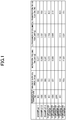
- FIG. 1 for eachof the carbonmaterials according to Examples 1 to 3 and Comparative Examples 1 to 5, the carbonization temperature (°C), the specific surface area (m 2 /g), the micropore volume (cm 3 /g), the ultramicropore volume (cm 3 /g), and the ratio (%) of the ultramicropore volume to the micropore volume are shown.
- the specific surface area and the pore volumes could not be appropriately measured. A possible reason for this is the possibility that the pore sizes were too small to be suited for the CO 2 adsorption and desorption measurement.
- the specific surface area measured by the BET method based on CO 2 gas adsorption was from 580 m 2 /g to 726 m 2 /g in Examples 1 to 3 where the carbonization temperature was from 800°C to 1,200°C, and was larger than that in Comparative Examples 1 to 3 where the carbonization temperatures were 600°C, 1,500°C, and 2,000°C.
- the ratio of the ultramicropore volume to the micropore volume in Examples 1 to 3 was from 70.6% to 91.7%, and was larger than that in Comparative Examples 1 to 5. That is, the micropores of each of the carbon materials according to Examples 1 to 3 included ultramicropores at a volume ratio of 70% or more and 95% or less.
- Ultramicropores each having a size of 0.7 nm or less are suited for hydrogen storage at normal temperature. Therefore, it was considered that each of the carbon materials according to Examples 1 to 3 having a large ratio of the ultramicropores had a carbon structure particularly suited for hydrogen storage.
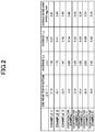
- the position of the top of the diffraction peak appearing in the diffraction angle 2 ⁇ range of from 18° to 26° obtained by the powder X-ray diffraction measurement was from 21.6° to 22.1° in Examples 1 to 3.
- the peak top positions in Comparative Examples 3 and 4 were 24.4° and 26.0°, respectively.
- a diffraction peak appearing at a diffraction angle 2 ⁇ of around 25° in X-ray diffraction is a peak derived from a carbon structure having high crystallinity.
- the XRD peak top position of each of the carbon materials according to Examples 1 to 3 was less than 25°, and hence the crystallinity of each of the carbon materials was considered tobe lower than those of the carbonmaterials according to Comparative Examples 3 and 4.
- the carbon materials according to Examples 1 to 3 each had an average La of from 1.49 nm to 1.90 nm. That is, the spread of the carbon network planes in the a-axis direction of each of the carbon materials according to Examples 1 to 3 was relatively small, and it was considered that a large number of edges were formed by disconnection of the carbon network planes.
- the carbon materials according to Examples 1 to 3 each had an average Lc of from 0.37 nm to 0.42 nm.
- the carbon material according to Comparative Example 1 obtained by the carbonization at 600°C had an average Lc of 0.34, which was smaller than those of Examples 1 to 3.
- the carbon materials according to Comparative Examples 2 and 3 obtained by the carbonization at 1,500°C or 2,000°C, and the carbon material according to Comparative Example 4 obtained by the carbonization of the raw material containing a metal each had an average Lc of from 0.50 nm to 0.69 nm, which was larger than those of Examples 1 to 3. That is, it was confirmed that the stacking structure of the carbon network planes of each of the carbon materials according to Examples 1 to 3 was more developed than that of Comparative Example 1, but was less developed than those of Comparative Examples 2 to 4.
- the carbon materials according to Examples 1 to 3 each had an average interlayer space d 002 of from 0.40nm to 0.41nm.
- the carbon material according to Comparative Example 1 obtained by the carbonization at 600°C had an average interlayer space d 002 of 0.49 nm, which was larger than those of Examples 1 to 3.
- the carbon materials according to Comparative Examples 2 and 3 obtained by the carbonization at 1,500°C or 2,000°C, and the carbon material according to Comparative Example 4 obtained by the carbonization of the raw material containing a metal each had an average interlayer space d 002 of from 0.34 nm to 0.39 nm, which was smaller than those of Examples 1 to 3.
- the activated carbon according to Comparative Example 5 had an average interlayer space d 002 of 0.36. That is, the average interlayer space d 002 of each of Comparative Examples 2 to 4 was comparable to that of the graphite crystal in Comparative Example 5, whereas the average interlayer space d 002 of each of Examples 1 to 3 was larger than those of the Comparative Examples 2 to 5.
- the average interlayer space d 002 of the carbon material according to Comparative Example 2 was even larger than those of the carbon materials according to Examples 1 to 3, and its crystallinity was considered to be lower.
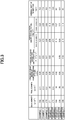
- the bulk density (g/cm 3 ), the true density (g/cm 3 ), the hydrogen storage amount at a hydrogen pressure of 10 MPa (wt%), the hydrogen storage amount per unit surface area ( ⁇ 10 -5 g/m 2 ), the hydrogen storage amount per unit volume based on the bulk density or the true density (mg/cm 3 ), and the chemical shift (ppm) of a peak in 1 H-NMR measurement are shown.
- the carbon materials according to Examples 1 to 3 each had a bulk density of from 0.73 g/cm 3 to 0.88 g/cm 3 and a true density of from 2.11 g/cm 3 to 2.21 g/cm 3 , which were larger than those of Comparative Examples 1 and 3 to 5.
- the carbon materials according to Examples 1 to 3 each had a hydrogen storage amount of from 0.39 wt% to 0.42 wt%, which was larger than those of the carbon materials according to Comparative Examples 1 to 5.
- the carbon materials according to Examples 1 to 3 each had a hydrogen storage amount per unit surface area of from 0.57 ⁇ 10 -5 g/m 2 to 0.67 ⁇ 10 -5 g/m 2 , which was larger than those of Comparative Examples 1, 4, and 5.
- the carbon materials according to Examples 1 to 3 each had a hydrogen storage amount per unit volume based on the bulk density of from 2. 85 mg/cm 3 to 3.70 mg/cm 3 , and a hydrogen storage amount per unit volume based on the true density of from 8.23 mg/cm 3 to 8.90 mg/cm 3 , which were both significantly larger than those of the carbon materials according to Comparative Examples 1 to 5.
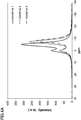
- FIG. 4A and FIG. 4B for the carbon materials according to Examples 1 to 3 and the carbon materials according to Comparative Examples 1 to 5, respectively, the NMR spectra obtained by the Fourier transform of signals in 1 H-NMR measurement are shown.
- the axis of abscissa represents a chemical shift (ppm)
- the axis of ordinate represents a signal intensity.
- the hydrogen introduced into each of the carbon materials according to Comparative Example 1 and Comparative Example 3 exhibited, in the NMR spectrum, a single peak (first peak) as in the case of hydrogen gas alone.
- the first peak had a relatively small shift from the reference frequency, and hence was considered to be attributed to gaseous hydrogen (hydrogen gas) present in voids in the sample.
- the hydrogen introduced into each of the carbon materials according to Examples 1 to 3 exhibited, in addition to the first peak, a second peak at a position shifted to the high magnetic field side with respect to the first peak.
- the secondpeak had a relatively large chemical shift and was dependent on the hydrogen storage amount per unit surface area, and hence was considered to be attributed to hydrogen adsorbed on the carbon material.
- Comparative Example 2 As shown in FIG. 4B , in Comparative Example 2 also, the second peak was shown in addition to the first peak. However, as described above, the carbon material according to Comparative Example 2 had a small specific surface area and a small ratio of ultramicropores compared to those of the carbon materials according to Examples 1 to 3, and was considered not to sufficiently have a carbon structure suited for hydrogen storage.
Landscapes
- Chemical & Material Sciences (AREA)
- Organic Chemistry (AREA)
- Inorganic Chemistry (AREA)
- Analytical Chemistry (AREA)
- Chemical Kinetics & Catalysis (AREA)
- Engineering & Computer Science (AREA)
- Physics & Mathematics (AREA)
- High Energy & Nuclear Physics (AREA)
- Materials Engineering (AREA)
- Combustion & Propulsion (AREA)
- Immunology (AREA)
- Pathology (AREA)
- General Physics & Mathematics (AREA)
- General Health & Medical Sciences (AREA)
- Biochemistry (AREA)
- Life Sciences & Earth Sciences (AREA)
- Health & Medical Sciences (AREA)
- Nanotechnology (AREA)
- Carbon And Carbon Compounds (AREA)
- Hydrogen, Water And Hydrids (AREA)
- Solid-Sorbent Or Filter-Aiding Compositions (AREA)
Abstract
Description
- The present invention relates to a hydrogen storage carbon material.
- Hydrogen is drawing attention as a clean energy source that does not generate carbon dioxide even whenburnt. In order to utilize hydrogen as a fuel, a method of storing and transporting hydrogen has been investigated. As the method of storing and transporting hydrogen, a method involving using a high-pressure gas cylinder is generally used. However, the gas cylinder is heavy. Inaddition, storage efficiency per unit volume of the gas cylinder has a practical limit, and a significant increase in storage efficiency cannot be expected.
- As a hydrogen storage method that replaces the gas cylinder, various materials have heretofore been investigated for hydrogen storage. For example, a method involving utilizing a hydrogen storage alloy has been known. However, the hydrogen storage alloy has a drawback in that the hydrogen storage alloy itself is heavy, and requires heat for releasing hydrogen. For these and other reasons, the range of application of the hydrogen storage alloy is limited. Therefore, there is a demand for development of a material that is more lightweight than the hydrogen storage alloy and that has high hydrogen storage capacity.
- In this regard,
Patent Literature 1 discloses a porous carbon material in which a volume of pores each having a diameter of 1 nm or less is more than 0.2 cm3/g, and in which a ratio of the volume of the pores each having a diameter of 1 nm or less to a total pore volume is 85% or more. - [Patent Literature 1]
JP 2009-249222 A - However, the related-art carbon material did not necessarily have a carbon structure suited for hydrogen storage.
- The present invention has been made in view of the above-mentioned problem, and one of the objects of the present invention is to provide a hydrogen storage carbon material having a carbon structure suited for hydrogen storage, and a production method thereof.
- In order to solve the above-mentioned problem, a hydrogen storage carbon material according to one embodiment of the present invention includes a carbon structure which has a ratio of an ultramicropore volume to a micropore volume of 60% or more, and in which stored hydrogen exhibits, in 1H-NMR measurement, a second peak at a position corresponding to a chemical shift of from -2 ppm to -20 ppm with respect to a first peak attributed to gaseous hydrogen. According to the one embodiment of the present invention, the hydrogen storage carbonmaterial having a carbon structure suited for hydrogen storage is provided.
- The hydrogen storage carbon material may be free of a metal inside. The carbon structure may have an average crystallite size La in an a-axis direction of 1.00 nm or more and 2.50 nm or less. The micropore volume may be 0.19 cm3/g or more and 0.40 cm3/g or less. The hydrogen storage carbon material may have a true density of 1.40 g/cm3 or more and 3.00 g/cm3 or less. The hydrogen storage carbon material may have a carbon structure exhibiting a peak having a peak top position of 18.0° or more and 25.0° or less in powder X-ray diffraction.
- According to the present invention, the hydrogen storage carbon material having a carbon structure suited for hydrogen storage and the production method thereof are provided.
-
-
FIG. 1 is a table which shows the results of evaluation of characteristics, such as an ultramicropore volume, of carbon materials in Examples according to one embodiment of the present invention. -
FIG. 2 is a table which shows the results of evaluation of characteristics, such as an average crystallite size La in an a-axis direction of a carbon structure, of carbon materials in Examples according to one embodiment of the present invention. -
FIG. 3 is a table which shows the results of evaluation of characteristics, such as a chemical shift in 1H-NMR measurement, in Examples according to one embodiment of the present invention. -
FIG. 4A is an explanatory diagram which shows examples of NMR spectra obtained by 1H-NMR measurement in Examples according to one embodiment of the present invention. -
FIG. 4B is an explanatory diagram which shows other examples of NMR spectra obtained by 1H-NMR measurement in Examples according to one embodiment of the present invention. - Now, an embodiment of the present invention will be described. The present invention is not limited to examples shown in this embodiment.
- Ahydrogen storage carbonmaterial according to this embodiment (hereinafter referred to as "carbon material of the present invention") includes a carbon structure which has a ratio of an ultramicropore volume to a micropore volume of 60% or more, and in which stored hydrogen exhibits, in 1H-NMR measurement, a second peak at a position corresponding to a chemical shift of from -2 ppm to -20 ppm with respect to a first peak attributed to gaseous hydrogen.
- The carbon material of the present invention is a carbon material having hydrogen storage capacity. That is, the carbon material of the present invention is preferably applied to various apparatus and systems each utilizing hydrogen as a fuel. Therefore, this embodiment encompasses a use of the carbon material of the present invention in hydrogen storage, and a method of using the carbon material of the present invention for hydrogen storage. Hydrogen storage with the carbon material of the present invention is performed by, for example, bringing hydrogen to be used as a fuel into contact with the carbon material of the present invention at high pressure to cause the carbonmaterial of the present invention to store the hydrogen. In addition, the hydrogen may be released from the carbon material of the present invention storing the hydrogen by decreasing the pressure of the hydrogen.
- The carbon structure of the carbon material of the present invention contains micropores, and the micropores include ultramicropores. The micropores are pores each having a pore diameter of 2 nm or less (for example, a pore diameter measured by carbon dioxide adsorption of 0.48 nm or more and 2 nm or less) . The ultramicropores are pores each having a pore diameter of 0.7 nm or less (for example, a pore diameter measured by carbon dioxide adsorption of 0.48 nm or more and 0.7 nm or less).
- The carbon material of the present invention has such ultramicropores that the ratio of their ultramicropore volume to the micropore volume is 60% or more (60% or more and 100% or less) . That is, in the carbon material of the present invention, the ultramicropores account for a relatively large ratio in the micropores.
- The ratio of the ultramicropore volume to the micropore volume in the carbon material of the present invention is preferably 65% or more (65% or more and 100% or less), particularly preferably 70% or more (70% or more and 100% or less).
- The carbon material of the present invention further has the carbon structure in which stored hydrogen shows, in 1H-NMR measurement, the second peak at a position corresponding to a chemical shift of from -2 ppm to -20 ppm with respect to the first peak attributed to gaseous hydrogen.
- That is, an NMR spectrum obtained by 1H-NMR measurement of the carbon material of the present invention storing hydrogen contains the first peak attributed to gaseous hydrogen, and the second peak at a position shifted from the position of the first peak to a high magnetic field side by from 2 ppm to 20 ppm.
- As described above, when the carbon material of the present invention storing hydrogen is subjected to 1H-NMR measurement, the second peak peculiar to the hydrogen adsorbed on the carbon material of the present invention, which is different from that of gaseous hydrogen (hydrogen gas), appears at a position corresponding to a chemical shift in the specific range.
- The chemical shift of the second peak of the carbon material of the present invention may be, for example, from -3 ppm to -15 ppm, from -3 ppm to -12 ppm, from -4 ppm to -12 ppm, or from -4 ppm to -10 ppm.
- As described above, the carbon material of the present invention has the peculiar carbon structure suited for hydrogen storage, which contains the ultramicropores at a high ratio, and in which stored hydrogen exhibits a chemical shift in the specific range. That is, the carbon material of the present invention has, at a high ratio, such ultramicropores that stored hydrogen exhibits a chemical shift in the specific range.
- The carbon material of the present invention is produced by a method including heating a raw material containing an organic compound while increasing its temperature at a temperature increase rate of less than 50°C/h, and carbonizing the raw material at a temperature of 300°C or more and 2,000°C or less.
- The organic compound contained in the raw material for the carbonization is not particularly limited as long as the organic compound can be carbonized (can be used as a carbon source), and an organic low-molecular-weight compound and/or an organic high-molecular-weight compound are/is used. Of those, an organic high-molecular-weight material is preferably used.
- The organic high-molecular-weight compound is not particularly limited, and there may be used, for example, one or more kinds selected from a group consisting of a phenolic resin, polyacrylonitrile, polyvinylpyridine, a chelate resin, cellulose, carboxymethyl cellulose, polyvinyl alcohol, polyacrylic acid, polymethyl acrylate, polymethyl methacrylate, polyfurfurylalcohol, afuranresin, a phenol formaldehyde resin, polyimidazole, a melamine resin, an epoxy resin, pitch, lignite, polyvinylidene chloride, polycarbodiimide, lignin, anthracite, biomass, a protein, humic acid, polysulfone, polyaminobismaleimide, polyimide, polyaniline, polypyrrole, and an ionomer.
- The carbonization is performed by heating the raw material and keeping the raw material at a predetermined temperature (carbonization temperature) at which the organic compound contained in the raw material is carbonized. The carbonization temperature is not particularly limited as long as the carbonization temperature is a temperature at which the organic compound contained in the raw material is carbonized. The carbonization temperature may be, for example, 300°C or more and 2,000°C or less, more than 600°C and less than 1,500°C, or 700°C or more and 1,400°C or less.
- A period of time for which the raw material is kept at the carbonization temperature is not particularly limited as long as the organic compound contained in the raw material is carbonized at the temperature. The period of time may be, for example, 5 minutes or more and 24 hours or less. The carbonization is preferably performed under a stream of an inert gas, for example, nitrogen.
- In the carbonization in the production of the carbon material of the present invention, a relatively small temperature increase rate of less than 50°C/h is employed. Specifically, for example, when the carbonization temperature is 1, 000°C or less, the heating to the carbonization temperature may be performed at a temperature increase rate of less than 50°C/h, and when the carbonization temperature is more than 1,000°C, the heating to at least 1, 000°C may be performed at a temperature increase rate of less than 50°C/h.
- The temperature increase rate may be, for example, 45°C/h or less. More specifically, the temperature increase rate may be, for example, 20°C/h or more and less than 50°C/h, 20°C/h or more and 45°C/h or less, or 30°C/h or more and 45°C/h or less.
- In the production of the carbon material of the present invention, a relatively high carbonization temperature and a relatively small temperature increase rate are preferably adopted. That is, in the production of the carbon material of the present invention, for example, the raw material may be: heated while its temperature is increased at a temperature increase rate of less than 50°C/h; and carbonized at a temperature of more than 600°C and less than 1,500°C, or may be: heated while its temperature is increased at a temperature increase rate of less than 50°C/h; and carbonized at a temperature of 700°C or more and 1, 400°C or less.
- When the carbonization is performed while the heating is performed at such small temperature increase rate, the carbon material of the present invention having the carbon structure suited for hydrogen storage as described above is efficiently produced.
- The carbon material of the present invention may be free of a metal in the inside thereof. That is, in this case, the carbon material of the present invention is produced by a method including heating a raw material containing an organic compound and no metal while increasing its temperature at a temperature increase rate of less than 50°C/h, and carbonizing the rawmaterial at a temperature of 300°C or more and 2,000°C or less.
- The carbon material of the present invention may have a micropore volume of 0.19 cm3/g or more and 0.40 cm3/g or less. In this case, the micropore volume of the carbon material of the present invention may be, for example, 0.20 cm3/g or more and 0.30 cm3/g or less.
- The carbon material of the present invention may have an ultramicropore volume of 0.12 cm3/g or more and 0.39 cm3/g or less. In this case, the ultramicropore volume of the carbon material of the present invention may be, for example, 0.12 cm3/g or more and 0.36 cm3/g or less, or 0.12 cm3/g or more and 0.29 cm3/g or less.
- The carbon structure of the carbon material of the present invention may have an average crystallite size La (average La) in an a-axis direction of 1.00 nm or more and 2.50 nm or less. In this case, the average La of the carbon material of the present invention may be, for example, 1.10 nm or more and 2.40 nm or less, or 1.30 nm or more and 2.00 nm or less.
- The average La corresponds to a diameter of a circle in a case where a plane formed by the two-dimensional spreading of a carbon network plane included in the carbon structure is approximated to the circle, and the average La indicates the degree of the spread of the plane. When the average La falls within any one of the above-mentioned ranges, the carbon structure of the carbon material of the present invention has a relatively small spread of the carbon network plane in the a-axis direction, and includes many edge surfaces formed by frequent disconnection of the carbon network plane.
- The carbon structure of the carbon material of the present invention may have an average crystallite size Lc (average Lc) in a c-axis direction of 0.20 nm or more and 0.65 nm or less. In this case, the average Lc of the carbon material of the present invention may be, for example, 0.30 nm or more and 0.60 nm or less, or 0.35 nm or more and 0.45 nm or less.
- The average Lc indicates the thickness in the c-axis direction of a group of carbon network planes stacked parallel to each other included in the carbon structure. When the average Lc falls within the above-mentioned range, the carbon material of the present invention has a carbon structure in which a stacking structure in the c-axis direction is developed. As the average Lc increases, the carbon material of the present invention has a carbon structure in which the stacking number of carbon network planes is larger.
- The carbon structure of the carbon material of the present invention may have an average (002) interlayer space d002 (average interlayer space d002) of 0.35 nm or more and 0.50 nm or less. In this case, the average interlayer space d002 of the carbon material of the present invention may be, for example, 0.37 nm or more and 0.45 nm or less, or 0.40 nm or more and 0.42 nm or less. The average interlayer space d002 is an average distance between carbon (002) planes forming the carbon structure.
- The carbonmaterial of the present invention may have a specific surface area, determined by carbon dioxide adsorption, of 20 m2/g or more and 1,000 m2/g or less. In this case, the specific surface area of the carbon material of the present invention may be, for example, 200 m2/g or more and 900 m2/g or less, or 560 m2/g or more and 800 m2/g or less.
- The carbon material of the present invention may have a bulk density of 0.60 g/cm3 or more and 3.00 g/cm3 or less. In this case, the bulk density of the carbon material of the present invention may be, for example, 0.70 g/cm3 or more and 1.50 g/cm3 or less, or 0.72 g/cm3 or more and 0.90 g/cm3 or less.
- The carbon material of the present invention may have a true density of 1.40 g/cm3 or more and 3.00 g/cm3 or less. In this case, the true density of the carbon material of the present invention may be, for example, 1.50 g/cm3 or more and 2.50 g/cm3 or less, or 2.10 g/cm3 or more and 2.25 g/cm3 or less.
- The carbon material of the present invention may have a carbon structure exhibiting a peak having a peak top position of 18.0° or more and 25.0° or less in powder X-ray diffraction. That is, when the carbon material of the present invention is subjected to powder X-ray diffraction, a peak having a peak top position of 18.0° or more and 25.0° or less is observed in the diffraction angle 2θ range of from 18° or more to 26° or less. The peak top position may be, for example, 19.0° or more and 25.0° or less, or 21.0° or more and 23.0° or less.
- The carbonmaterial of the present inventionmay have a hydrogen storage amount, measured at 298 K and a hydrogen pressure of 10 MPa by a method in conformity with JIS H 7201, of 0.05 wt% or more. Specifically, the hydrogen storage amount of the carbon material of the present invention may be, for example, 0.30 wt% or more, or 0.33 wt% or more.
- The carbonmaterial of the present inventionmayhave a hydrogen storage amount per unit surface area, calculated by dividing the above-mentioned hydrogen storage amount by the above-mentioned specific surface area, of 0.40×10⁻⁵ g/m2 or more. Specifically, the hydrogen storage amount per unit surface area of the carbon material of the present invention may be, for example, 0.46×10⁻⁵ g/m2 or more, or 0.53×10⁻⁵ g/m2 or more.
- The carbonmaterial of the present invention may have a hydrogen storage amount per unit volume, calculated by dividing the above-mentioned hydrogen storage amount by the above-mentioned bulk density, of 0. 50 mg/cm3 or more. Specifically, the hydrogen storage amount per unit volume of the carbon material of the present invention based on the bulk density may be, for example, 1.00 mg/cm3 or more, or 2.80 mg/cm3 or more.
- The carbonmaterial of the present inventionmayhave a hydrogen storage amount per unit volume, calculated by dividing the above-mentioned hydrogen storage amount by the above-mentioned true density, of 1.00 mg/cm3 or more. Specifically, the hydrogen storage amount per unit volume of the carbon material of the present invention based on the true density may be, for example, 5.00 mg/cm3 or more, or 8.20 mg/cm3 or more.
- Next, specific Examples according to this embodiment will be described.
- In Example 1, a hydrogen storage carbon material was produced by carbonizing a raw material containing an organic compound and being free of a metal. That is, beads each made of a phenolic resin (100 µm, manufactured by Gunei Chemical Industry Co., Ltd.) were heated under a vacuum to increase their temperature from room temperature to 800°C at a temperature increase rate of 48°C/h, and were then kept at a carbonization temperature of 800°C for 1 hour to be carbonized. After the carbonization, the temperature was lowered to room temperature by natural cooling. The obtained carbon material free of a metal in the inside thereof was used as a hydrogen storage carbon material according to Example 1. In Example 2, a hydrogen storage carbon material was produced in the same manner as in Example 1 described above except that the carbonization temperature was changed to 1,000°C.
- In Example 3, beads each made of a phenolic resin (100 µm, manufactured by Gunei Chemical Industry Co. , Ltd.) were heated under a vacuum to increase their temperature from room temperature to 1,000°C at a temperature increase rate of 48°C/h, and further increase their temperature from 1,000°C to 1,200°C at a temperature increase rate of 100°C/h, and were then kept at a carbonization temperature of 1,200°C for 1 hour to be carbonized. After the carbonization, the temperature was lowered to room temperature by natural cooling. The obtained carbon material free of a metal in the inside thereof was used as a hydrogen storage carbon material according to Example 3.
- In Comparative Example 1, a hydrogen storage carbon material was produced in the same manner as in Example 1 described above except that the carbonization temperature was changed to 600°C. In Comparative Example 2, a hydrogen storage carbon material was produced in the same manner as in Example 3 described above except that the carbonization temperature was changed to 1,500°C. In Comparative Example 3, a hydrogen storage carbon material was produced in the same manner as in Example 3 described above except that the carbonization temperature was changed to 2,000°C.
- In Comparative Example 4, a hydrogen storage carbon material was produced by carbonizing a raw material containing an organic compound and a metal. That is, 10 g of a phenolic resin, 3.05 g of iron phthalocyanine, and acetone serving as a solvent were mixed, and the resultant solution was dried to provide a solid. The solid was heated under a nitrogen atmosphere to increase its temperature from room temperature to 800°C at a temperature increase rate of 10°C/min, and was then kept at a carbonization temperature of 800°C for 1 hour tobe carbonized. After the carbonization, the temperature was lowered to room temperature by natural cooling. The obtained carbon material was pulverized, and the carbon material pulverized and containing a metal (iron) inside was used as a hydrogen storage carbon material according to Comparative Example 4. Commercially available activated carbon (4H, manufactured by Tsurumi Coal Co., Ltd.) was used as a hydrogen storage carbon material according to Comparative Example 5.
- CO2 adsorption and desorption measurement was performed at 273 K. That is, the specific surface area, micropore volume, and ultramicropore volume of each of the carbon materials obtained as described above were measured using a high-pressure gas adsorption amount-measuring apparatus (BELSORP-HP, BEL Japan, Inc.).
- Specifically, first, 1 g of a carbon material was kept at 300°C and a pressure of 1 Pa or less for 2 hours to remove moisture adsorbed on the carbon material. Then, adsorption measurement in the CO2 gas pressure range of from 0 MPa to 3.45 MPa was performed. With the use of the resultant adsorption isotherm, the specific surface area of the carbon material was calculated by a BET method. Further, the volume of micropores (pores each having a size of 2 nm or less) of the carbon material, and the volume of its ultramicropores (pores each having a size of 0.7 nm or less) were calculated by the HK method.
- The HK method is a technique devised by Horvath and Kawazoe in order to determine the pore distribution of slit-shapedmicropores, is capable of calculating a pore diameter distribution from an adsorption isotherm, and is considered to be effective for analysis of micropores ("Method for the Caluculation of Effective Pore Size Distribution in Molecular Sieve Carbon", Geza Horvath and Kunitaro Kawazoe, J. Chem. Eng. Japan, 16, 470 (1983)). Horvath and Kawazoe determined a change in free energy in a case in which a gap between graphite layers or a slit-shaped pore was filled with gas molecules, and expressed a relationship between a relative pressure and a distance between the graphite layers (slit-shaped pore) by the following equation:

- In the equation, R represents an ideal gas constant, T represents an absolute temperature, L represents Avogadro's number, Ns represents the number of atoms per unit surface area of an adsorbent, As represents the Lennard-Jones constant of an adsorbate, Na represents the number of molecules per unit surface area of the adsorbate in an adsorbed state, Aa represents the Lennard-Jones constant for the adsorbate at zero interaction energy, 1 represents the interlayer distance of a slit-shaped pore (pore diameter), d represents the sum of the diameter dA (nm) of an adsorbate molecule and the diameter da (nm) of an adsorbent molecule, and σ represents a distance between an adsorbent surface and an adsorbate atom at zero interaction energy.
- In analysis using analysis software included with the above-mentioned high-pressure gas adsorption amount-measuring apparatus analysis, a pore diameter was first determined, and then a relative pressure corresponding to the pore diameter was calculated. Next, an adsorption amount at the relative pressure was calculated by linear interpolation of the adsorption data obtained by the above-mentioned CO2 adsorption and desorption measurement, and the resultant adsorption amount was plotted against the pore diameter to derive an integral curve. Then, the integral curve was differentiated to determine a pore distribution curve. From the result, the volume of micropores (pores of 2 nm or less), and the volume of ultramicropores (pores of 0.7 nm or less) were calculated. For the analysis, data for a low-pressure region (relative pressure of 0.530 or less) was used.
- A weighed carbon material was gently placed in a dry graduated cylinder without being compressed. After that, the top surface of the powder layer was carefully leveled without being compressed, and its volume was read to the minimum scale unit to determine the bulk density (g/cm3) of the carbon material.
- A true density was measured at 25 °C by a gas replacement method through the use of a dry automatic densimeter (AccuPyc II 1340, manufactured by Micromeritics Instrument Corporation) and He gas.
- First, a sample of a carbon material was placed in a concave portion of a glass sample plate, and was pressed with a slide glass. Thus, the sample was uniformly loaded into the concave portion so that its surface and a reference surface were flush with each other. Then, the glass sample plate was fixed on a wide-angle X-ray diffraction sample stage so that the morphology of the loaded sample did not collapse. Then, powder X diffraction measurement of each sample was performed using an X-ray diffraction apparatus (Rigaku RINT2100/PC, Rigaku Corporation) to measure a diffraction peak, and integration was performed five times. Thus, X-ray diffraction data to be analyzed was obtained. A voltage and a current applied to an X-ray tube were 50 kV and 300 mA, respectively, a sampling interval was 0.1° or 0.01°, a scanning rate was 1°/min, and a measurement angle range (2θ) was from 5° to 90°. In addition, a CuKα ray was used as an incident X-ray. Then, on the basis of the resultant X-ray diffraction pattern, the position of the top of a diffraction peak appearing in the diffraction angle 2θ range of from 18° or more to 26° or less was identified.
- On the basis of the X-ray diffraction data obtained by the powder X-ray diffraction described above, evaluation for a crystallite size La was performed. That is, the average La and an La distribution were analyzed by using Diamond's method. For this analysis, software for analysis (Carbon Analyzer D series, Hiroyuki Fujimoto) installed in a computer was used. The data to be analyzed was limited to the eleven-band intensity of a carbon material measured using a CuKα ray as an X-ray source and using a counter graphite monochrometer. The maximum analyzable network plane size was about 7 nm.
- The procedure of the analysis method proposed by Diamond is basically formed of the following six steps: (1) the measurement of the eleven-band intensity of a sample; (2) the correction of a measured intensity; (3) the assumption of model network planes expected to exist in the sample; (4) the calculation of theoretical scattering intensities from the assumed model network planes; (5) the least-square fitting of the determined measured intensity with the theoretical scattering intensities; and (6) the calculation of the weight fractions of the model network planes and an average network plane size from the weights of the respective theoretical scattering intensities. In view of the foregoing, first, the data to be analyzed was read, and was subjected to smoothing processing and absorption correction. The smoothing processing was performed with the number of smoothing points set to seven, and the absorption correction was performed using a theoretical absorption coefficient of 4.219.
- Next, the theoretical scattering intensities were calculated. The following equation (I) was used as a calculation equation. In the equation (I), I represents the measured intensity, w represents a mass fraction, B represents a theoretical X-ray scattering intensity, P represents a polarization factor, and v and s each represent a network plane model factor.

- In this case, all parameters can be represented as a function of n (see Hiroyuki Fujimoto, Carbon, 192 (2000) 125-129). The calculation of the theoretical scattering intensities requires, as the setting of initial conditions, the determination of a two-dimensional lattice constant a0 and a Ruland coefficient, and the selection of the model network planes. The two-dimensional lattice constant is generally set to a value between the lattice constants of benzene and ideal graphite, i.e., from about 0.240 nm to about 0.24612 nm. The Ruland coefficient indicates the integration width of a function showing the pass band of the energy of the monochrometer used, and generally takes a value of from 0 to 1. In this analysis, 0.24412 nm, a value close to the lattice constant of a general carbon material, was selected as the initially set value of the two-dimensional lattice constant a0, and 0.05 was selected as the initially set value of the Ruland coefficient.
- Next, the model network planes were selected. The above-mentioned software can execute the calculation of a theoretical intensity using three kinds of model network planes, i.e., a benzene-coronene base model, a pyrene base model, and a mixed model. In this regard, in this analysis, the benzene-coronene base model was used. In the case of this model, the scattering intensity of a model network plane having a size of an odd-number multiple (×1, 3, 5 ··· 25, 27, 29) of the two-dimensional lattice constant a0 (that is, the size is from about 0.25 nm to about 7 nm) can be calculated.
- All selection conditions were determined as described above, and the theoretical scattering intensities were calculated. After the completion of the calculation, repeated calculation by the least-square method based on the following equation (II) was performed 1,000 times, and a measured profile and a theoretical profile were fitted with each other with a fitting angle range 2θ set to from 60° to 100°. After the completion of the fitting, the display of the computer displayed a fitting result, a network plane size distribution, and an average network plane size.

- In addition, on the basis of the X-ray diffraction data obtained by the powder X-ray diffraction described above, evaluation for the stacking structure of carbon network planes in a carbon structure was performed. That is, an average Lc, the stacking number of carbon network planes and the distribution thereof, and an average interlayer space d002 were analyzed using the above-mentioned software for analysis (Carbon Analyzer D series, Hiroyuki Fujimoto) installed in a computer.
- In a calculation process using the software, the following five steps were performed: (1) the intensity correction of a diffraction line; (2) the correction of a background; (3) the calculation of a Patterson function; (4) the evaluation of validity by inverse Fourier transform; and (5) the calculation of the average Lc, an average stacking number, the stacking number distribution, and the average interlayer space d002 using the Patterson function.
- First, the diffraction data from 5° to 40° obtained by the X-ray diffraction measurement was subjected to the diffraction line intensity correction and the background correction. In the diffraction line intensity correction, a linear absorption coefficient µ of carbon was set to 4.219, a sample thickness t was set to 0.2 mm, a divergence slit width β was set to 2/3°, and a goniometer radius R was set to 285 mm. The background correction was performed by a spline interpolation method with base points set to around 15° and around 35°.
- Then, to the corrected data, Hirsch's method was applied in the diffraction angle range of from 5° to 40° to calculate the Patterson function. Further, the resultant Patterson function was subjected to the inverse Fourier transform to reconstruct a diffraction pattern. Thus, the validity of the Patterson function was evaluated. The Hirsch's method is a method proposed by Hirsch in 1954 in order to evaluate the average stacking number and stacking number distribution of carbon network planes in a sample having a relatively small network plane size, such as coal or pitch.
- The remaining calculation process was performed using the thus calculated Patterson function in accordance with the standard procedure of the software. Thus, the average Lc, the average stacking number, the stacking number distribution, and the average interlayer space d002 were calculated.
- A hydrogen storage amount at a hydrogen pressure of from 0 MPa to 11.5 MPa was measured at 298 K by a method in conformity to JIS H 7201. In addition, the obtained hydrogen storage amount (wt%) at a hydrogen pressure of 10 MPa was converted to a hydrogen storage amount (g) per 1 g of the carbon material, and the resultant value was divided by the bulk density or the true density to calculate a hydrogen storage amount per unit volume (mg/cm3).
- A sample of a carbon material was placed in a high-pressure NMR sample tube made of quartz. Then, piping for evacuation and gas introduction, and a valve were attached thereto, followed by degassing treatment at a temperature of 573 K and a final pressure of 1×10⁻⁴ torr for 24 hours. The sample after the degassing treatment was quickly placed in a probe while in the reduced-pressure state. Hydrogen was introduced thereinto to 3.5 MPa, and the resultant was subjected to measurement. 1H-NMR measurement was performed using an FT-NMR apparatus having mounted thereon a high-pressure and temperature-variable probe (Apollo Pulse NMR Spectrometer, 38 MHz, manufactured by Tecmag Inc.). A 90° pulse method was adopted for a pulse sequence. A measurement temperature was set to 173 K. The position of a peak (first peak) attributed to gaseous hydrogen (hydrogen gas: gas-phase hydrogen present between sample particles), which increased when the sample of the carbon material was loaded in an amount corresponding to a half of the high-pressure NMR sample tube made of quartz, was used as a reference (0 ppm), and the chemical shift of a peak (second peak) shifted to a high magnetic field side with respect to the first peak was evaluated. Hydrogen present on the plane of an aromatic ring shifts to the high magnetic field side, that is, a low ppm side due to the effect of the ring current of the aromatic ring. The amount of the shift corresponds to the degree of the development of a carbon network plane structure, and hydrogen stored in a carbon material surface having a developed carbon network plane structure or in pores shows a large shift. Therefore, the second peak was considered to be attributed to hydrogen adsorbed on the carbon material, and its peak shift amount was considered to change in a manner dependent on a change in structure of a storage site.
- In
FIG. 1 , for eachof the carbonmaterials according to Examples 1 to 3 and Comparative Examples 1 to 5, the carbonization temperature (°C), the specific surface area (m2/g), the micropore volume (cm3/g), the ultramicropore volume (cm3/g), and the ratio (%) of the ultramicropore volume to the micropore volume are shown. For the carbon material according to Comparative Example 3, the specific surface area and the pore volumes could not be appropriately measured. A possible reason for this is the possibility that the pore sizes were too small to be suited for the CO2 adsorption and desorption measurement. - As shown in
FIG. 1 , the specific surface area measured by the BET method based on CO2 gas adsorption was from 580 m2/g to 726 m2/g in Examples 1 to 3 where the carbonization temperature was from 800°C to 1,200°C, and was larger than that in Comparative Examples 1 to 3 where the carbonization temperatures were 600°C, 1,500°C, and 2,000°C. - In addition, the ratio of the ultramicropore volume to the micropore volume in Examples 1 to 3 was from 70.6% to 91.7%, and was larger than that in Comparative Examples 1 to 5. That is, the micropores of each of the carbon materials according to Examples 1 to 3 included ultramicropores at a volume ratio of 70% or more and 95% or less.
- Ultramicropores each having a size of 0.7 nm or less are suited for hydrogen storage at normal temperature. Therefore, it was considered that each of the carbon materials according to Examples 1 to 3 having a large ratio of the ultramicropores had a carbon structure particularly suited for hydrogen storage.
- In
FIG. 2 , for each of the carbonmaterials according to Examples 1 to 3 and Comparative Examples 1 to 5, the XRD peak top position (2θ/°), the average La (nm), the average Lc (nm), and the average interlayer space d002 (nm) are shown. - As shown in
FIG. 2 , the position of the top of the diffraction peak appearing in the diffraction angle 2θ range of from 18° to 26° obtained by the powder X-ray diffraction measurement (XRD peak top position) was from 21.6° to 22.1° in Examples 1 to 3. In contrast, the peak top positions in Comparative Examples 3 and 4 were 24.4° and 26.0°, respectively. - In this regard, a diffraction peak appearing at a diffraction angle 2θ of around 25° in X-ray diffraction is a peak derived from a carbon structure having high crystallinity. In this regard, as described above, the XRD peak top position of each of the carbon materials according to Examples 1 to 3 was less than 25°, and hence the crystallinity of each of the carbon materials was considered tobe lower than those of the carbonmaterials according to Comparative Examples 3 and 4.
- The carbon materials according to Examples 1 to 3 each had an average La of from 1.49 nm to 1.90 nm. That is, the spread of the carbon network planes in the a-axis direction of each of the carbon materials according to Examples 1 to 3 was relatively small, and it was considered that a large number of edges were formed by disconnection of the carbon network planes.
- The carbon materials according to Examples 1 to 3 each had an average Lc of from 0.37 nm to 0.42 nm. In contrast, the carbon material according to Comparative Example 1 obtained by the carbonization at 600°C had an average Lc of 0.34, which was smaller than those of Examples 1 to 3.
- The carbon materials according to Comparative Examples 2 and 3 obtained by the carbonization at 1,500°C or 2,000°C, and the carbon material according to Comparative Example 4 obtained by the carbonization of the raw material containing a metal each had an average Lc of from 0.50 nm to 0.69 nm, which was larger than those of Examples 1 to 3. That is, it was confirmed that the stacking structure of the carbon network planes of each of the carbon materials according to Examples 1 to 3 was more developed than that of Comparative Example 1, but was less developed than those of Comparative Examples 2 to 4.
- The carbon materials according to Examples 1 to 3 each had an average interlayer space d002 of from 0.40nm to 0.41nm. In contrast, the carbon material according to Comparative Example 1 obtained by the carbonization at 600°C had an average interlayer space d002 of 0.49 nm, which was larger than those of Examples 1 to 3.
- The carbon materials according to Comparative Examples 2 and 3 obtained by the carbonization at 1,500°C or 2,000°C, and the carbon material according to Comparative Example 4 obtained by the carbonization of the raw material containing a metal each had an average interlayer space d002 of from 0.34 nm to 0.39 nm, which was smaller than those of Examples 1 to 3.
- The activated carbon according to Comparative Example 5 had an average interlayer space d002 of 0.36. That is, the average interlayer space d002 of each of Comparative Examples 2 to 4 was comparable to that of the graphite crystal in Comparative Example 5, whereas the average interlayer space d002 of each of Examples 1 to 3 was larger than those of the Comparative Examples 2 to 5. The average interlayer space d002 of the carbon material according to Comparative Example 2 was even larger than those of the carbon materials according to Examples 1 to 3, and its crystallinity was considered to be lower.
- In
FIG. 3 , for each of the carbonmaterials according to Examples 1 to 3 and Comparative Examples 1 to 5, the bulk density (g/cm3), the true density (g/cm3), the hydrogen storage amount at a hydrogen pressure of 10 MPa (wt%), the hydrogen storage amount per unit surface area (×10-5 g/m2), the hydrogen storage amount per unit volume based on the bulk density or the true density (mg/cm3), and the chemical shift (ppm) of a peak in 1H-NMR measurement are shown. - As shown in
FIG. 3 , the carbon materials according to Examples 1 to 3 each had a bulk density of from 0.73 g/cm3 to 0.88 g/cm3 and a true density of from 2.11 g/cm3 to 2.21 g/cm3, which were larger than those of Comparative Examples 1 and 3 to 5. The carbon materials according to Examples 1 to 3 each had a hydrogen storage amount of from 0.39 wt% to 0.42 wt%, which was larger than those of the carbon materials according to Comparative Examples 1 to 5. - The carbon materials according to Examples 1 to 3 each had a hydrogen storage amount per unit surface area of from 0.57×10⁻⁵ g/m2 to 0.67×10⁻⁵ g/m2, which was larger than those of Comparative Examples 1, 4, and 5. The carbon materials according to Examples 1 to 3 each had a hydrogen storage amount per unit volume based on the bulk density of from 2. 85 mg/cm3 to 3.70 mg/cm3, and a hydrogen storage amount per unit volume based on the true density of from 8.23 mg/cm3 to 8.90 mg/cm3, which were both significantly larger than those of the carbon materials according to Comparative Examples 1 to 5.
- In
FIG. 4A andFIG. 4B , for the carbon materials according to Examples 1 to 3 and the carbon materials according to Comparative Examples 1 to 5, respectively, the NMR spectra obtained by the Fourier transform of signals in 1H-NMR measurement are shown. In each ofFIG. 4A andFIG. 4B , the axis of abscissa represents a chemical shift (ppm), and the axis of ordinate represents a signal intensity. - As shown in
FIG. 4B , the hydrogen introduced into each of the carbon materials according to Comparative Example 1 and Comparative Example 3 exhibited, in the NMR spectrum, a single peak (first peak) as in the case of hydrogen gas alone. The first peak had a relatively small shift from the reference frequency, and hence was considered to be attributed to gaseous hydrogen (hydrogen gas) present in voids in the sample. - Meanwhile, as shown in
FIG. 4A , the hydrogen introduced into each of the carbon materials according to Examples 1 to 3 exhibited, in addition to the first peak, a second peak at a position shifted to the high magnetic field side with respect to the first peak. The secondpeakhad a relatively large chemical shift and was dependent on the hydrogen storage amount per unit surface area, and hence was considered to be attributed to hydrogen adsorbed on the carbon material. - As shown in
FIG. 4B , in Comparative Example 2 also, the second peak was shown in addition to the first peak. However, as described above, the carbon material according to Comparative Example 2 had a small specific surface area and a small ratio of ultramicropores compared to those of the carbon materials according to Examples 1 to 3, and was considered not to sufficiently have a carbon structure suited for hydrogen storage. - In view of the foregoing, as one reason that the carbon materials according to Examples 1 to 3 each exhibited high hydrogen storage capacity, it was considered that the carbon materials each had a peculiar carbon structure suited for hydrogen storage.
Claims (6)
- A hydrogen storage carbon material, comprising a carbon structure which has a ratio of an ultramicropore volume to a micropore volume of 60% or more, and in which stored hydrogen exhibits, in 1H-NMR measurement, a second peak at a position corresponding to a chemical shift of from -2 ppm to -20 ppm with respect to a first peak attributed to gaseous hydrogen.
- The hydrogen storage carbon material according to claim 1, wherein the hydrogen storage carbon material is free of a metal inside.
- The hydrogen storage carbon material according to claim 1 or 2, wherein the carbon structure has an average crystallite size La in an a-axis direction of 1.00 nm or more and 2.50 nm or less.
- The hydrogen storage carbon material according to any one of claims 1 to 3, wherein the micropore volume is 0.19 cm3/g or more and 0.40 cm3/g or less.
- The hydrogen storage carbon material according to any one of claims 1 to 4, wherein the hydrogen storage carbon material has a true density of 1.40 g/cm3 or more and 3.00 g/cm3 or less.
- The hydrogen storage carbon material according to any one of claims 1 to 5, wherein the carbon structure exhibits a peak having a peak top position of 18.0° or more and 25.0° or less in powder X-ray diffraction.
Applications Claiming Priority (2)
| Application Number | Priority Date | Filing Date | Title |
|---|---|---|---|
| JP2015138774A JP6572033B2 (en) | 2015-07-10 | 2015-07-10 | Hydrogen storage carbon material |
| PCT/JP2016/068187 WO2017010235A1 (en) | 2015-07-10 | 2016-06-17 | Hydrogen storage carbon material |
Publications (2)
| Publication Number | Publication Date |
|---|---|
| EP3320968A1 true EP3320968A1 (en) | 2018-05-16 |
| EP3320968A4 EP3320968A4 (en) | 2019-01-16 |
Family
ID=57756977
Family Applications (1)
| Application Number | Title | Priority Date | Filing Date |
|---|---|---|---|
| EP16824215.4A Pending EP3320968A4 (en) | 2015-07-10 | 2016-06-17 | CARBONACEOUS STORAGE SUBSTANCE OF HYDROGEN |
Country Status (5)
| Country | Link |
|---|---|
| US (1) | US10392249B2 (en) |
| EP (1) | EP3320968A4 (en) |
| JP (1) | JP6572033B2 (en) |
| CN (1) | CN107709230B (en) |
| WO (1) | WO2017010235A1 (en) |
Families Citing this family (1)
| Publication number | Priority date | Publication date | Assignee | Title |
|---|---|---|---|---|
| CN108565401B (en) * | 2018-05-18 | 2020-12-15 | 国家能源投资集团有限责任公司 | Amorphous carbon material and preparation method and use |
Family Cites Families (25)
| Publication number | Priority date | Publication date | Assignee | Title |
|---|---|---|---|---|
| US5614460A (en) * | 1995-08-23 | 1997-03-25 | Syracuse University | Microporous carbons for fuel gas storage |
| US6294501B1 (en) * | 1998-03-09 | 2001-09-25 | Alliedsignal Inc. | Special adsorbent for carbon dioxide acquisition on mars |
| US6670304B2 (en) | 1998-03-09 | 2003-12-30 | Honeywell International Inc. | Enhanced functionalized carbon molecular sieves for simultaneous CO2 and water removal from air |
| WO2000011688A1 (en) * | 1998-08-25 | 2000-03-02 | Kanebo, Limited | Electrode material and method for producing the same |
| US20050260118A1 (en) * | 2004-05-20 | 2005-11-24 | Yunfeng Lu | Mesoporous carbon films and methods of preparation thereof |
| JP2006335596A (en) * | 2005-06-01 | 2006-12-14 | Tohoku Univ | A convenient method for the synthesis of ordered large surface area microporous carbon |
| AU2007239058A1 (en) * | 2006-02-15 | 2007-10-25 | Rudyard Lyle Istvan | Mesoporous activated carbons |
| MX2009004951A (en) * | 2006-11-08 | 2009-07-27 | Univ Missouri | High surface area carbon and process for its production. |
| BRPI0718811B1 (en) * | 2006-11-15 | 2020-05-19 | Basf Se | double layer capacitance fixture |
| US8657923B2 (en) * | 2008-02-26 | 2014-02-25 | Nissan Motor Co., Ltd. | Microporous carbon material, manufacturing method thereof, and hydrogen storage method using microporous carbon material |
| JP2009249222A (en) * | 2008-04-04 | 2009-10-29 | Tokuyama Corp | Porous carbon material |
| WO2009149540A1 (en) * | 2008-06-10 | 2009-12-17 | National Research Council Of Canada | Controllable synthesis of porous carbon spheres, and electrochemical applications thereof |
| PL2448748T3 (en) * | 2009-07-01 | 2024-11-25 | Basf Mobile Emissions Catalysts Llc | Ultrapure synthetic carbon materials |
| WO2011084994A1 (en) * | 2010-01-05 | 2011-07-14 | Sigma-Aldrich Co. | Carbon molecular sieve for hydrogen storage and adsorption of other light gases |
| TWI400195B (en) * | 2010-01-08 | 2013-07-01 | Iner Aec Executive Yuan | Method for making hydrogen storage structure |
| JP4890623B2 (en) * | 2010-02-26 | 2012-03-07 | 国立大学法人群馬大学 | Hydrogen storage carbon material |
| WO2011112992A1 (en) * | 2010-03-12 | 2011-09-15 | Energ2, Inc. | Mesoporous carbon materials comprising bifunctional catalysts |
| WO2012045002A1 (en) * | 2010-09-30 | 2012-04-05 | Energ2 Technologies, Inc. | Enhanced packing of energy storage particles |
| JP2013112572A (en) * | 2011-11-29 | 2013-06-10 | Nagaoka Univ Of Technology | Hydrogen occlusion method, and hydrogen occluding material |
| US9597656B2 (en) * | 2012-01-11 | 2017-03-21 | William Marsh Rice University | Porous carbon materials for CO2 separation in natural gas |
| US9409777B2 (en) * | 2012-02-09 | 2016-08-09 | Basf Se | Preparation of polymeric resins and carbon materials |
| JP5683536B2 (en) * | 2012-06-08 | 2015-03-11 | 株式会社豊田自動織機 | Electric compressor |
| KR101438433B1 (en) * | 2012-10-09 | 2014-09-12 | 고려대학교 산학협력단 | Mesoporous carbon structures and preparation method thereof |
| WO2014077714A1 (en) | 2012-11-16 | 2014-05-22 | Politechnika Poznańska | Production of activated carbon from tobacco leaves by simultaneous carbonization and self-activation and the activated carbon thus obtained |
| US10147950B2 (en) * | 2015-08-28 | 2018-12-04 | Group 14 Technologies, Inc. | Materials with extremely durable intercalation of lithium and manufacturing methods thereof |
-
2015
- 2015-07-10 JP JP2015138774A patent/JP6572033B2/en active Active
-
2016
- 2016-06-17 CN CN201680037567.3A patent/CN107709230B/en active Active
- 2016-06-17 US US15/735,777 patent/US10392249B2/en active Active
- 2016-06-17 EP EP16824215.4A patent/EP3320968A4/en active Pending
- 2016-06-17 WO PCT/JP2016/068187 patent/WO2017010235A1/en not_active Ceased
Also Published As
| Publication number | Publication date |
|---|---|
| WO2017010235A1 (en) | 2017-01-19 |
| EP3320968A4 (en) | 2019-01-16 |
| JP2017019693A (en) | 2017-01-26 |
| US20180179057A1 (en) | 2018-06-28 |
| US10392249B2 (en) | 2019-08-27 |
| JP6572033B2 (en) | 2019-09-04 |
| CN107709230B (en) | 2021-05-04 |
| CN107709230A (en) | 2018-02-16 |
Similar Documents
| Publication | Publication Date | Title |
|---|---|---|
| Zhang et al. | Fundamentals of hydrogen storage in nanoporous materials | |
| Furukawa et al. | Independent verification of the saturation hydrogen uptake in MOF-177 and establishment of a benchmark for hydrogen adsorption in metal–organic frameworks | |
| Antoniou et al. | Methane storage in zeolite-like carbon materials | |
| Tan et al. | Quantum mechanical predictions to elucidate the anisotropic elastic properties of zeolitic imidazolate frameworks: ZIF-4 vs. ZIF-zni | |
| Kaneko et al. | Origin of superhigh surface area and microcrystalline graphitic structures of activated carbons | |
| Hofmann et al. | Small-angle x-ray diffraction of Kr in mesoporous silica: Effects of microporosity and surface roughness | |
| Furuya et al. | Interaction of hydrogen with carbon coils at low temperature | |
| Shiryaev et al. | Microporosity and nanostructure of activated carbons: characterization by X-ray diffraction and scattering, Raman spectroscopy and transmission electron microscopy | |
| Roberts et al. | The characterisation of slow-heated inertinite-and vitrinite-rich coals from the South African coalfields | |
| Rodrigues et al. | Microstructural evolution of high temperature treated anthracites of different rank | |
| Zetterström et al. | Reverse Monte Carlo studies of nanoporous carbon from TiC | |
| Gálvez et al. | Trapping and adsorption of CO2 in amorphous ice: A FTIR study | |
| Beebe et al. | Heats of adsorption of polar molecules on carbon surfaces. I. Sulfur dioxide | |
| Collings et al. | The interaction of carbon monoxide with model astrophysical surfaces | |
| Helmich et al. | Characterization of microporous activated carbons using molecular probe method | |
| US10392249B2 (en) | Hydrogen storage carbon material | |
| Koppel et al. | In situ observation of pressure modulated reversible structural changes in the graphitic domains of carbide-derived carbons | |
| Shahrak et al. | Synthesis, gas adsorption and reliable pore size estimation of zeolitic imidazolate framework-7 using CO2 and water adsorption | |
| Islam et al. | Improved CO2 capture capacity of waste sawmill dust derived activated carbon employing novel high-pressure CO2 activation | |
| Nguyen et al. | Porosity, powder X-Ray diffraction patterns, skeletal density, and thermal stability of NIST zeolitic reference materials RM 8850, RM 8851, and RM 8852 | |
| Trepte et al. | Theoretical and experimental investigations of 129 Xe NMR chemical shift isotherms in metal–organic frameworks | |
| Omi et al. | High-pressure 129 Xe NMR study of supercritical xenon confined in the mesopores of FSM-16 | |
| Floquet et al. | Confined water in mesoporous MCM-41 and nanoporous AlPO4-5: structure and dynamics | |
| Sato et al. | Surface fractal dimensional change of microporous carbon fibers with partial graphitization | |
| Kanamaru et al. | Pore-size control of soft mesoporous carbon by hot pressing |
Legal Events
| Date | Code | Title | Description |
|---|---|---|---|
| STAA | Information on the status of an ep patent application or granted ep patent |
Free format text: STATUS: THE INTERNATIONAL PUBLICATION HAS BEEN MADE |
|
| PUAI | Public reference made under article 153(3) epc to a published international application that has entered the european phase |
Free format text: ORIGINAL CODE: 0009012 |
|
| STAA | Information on the status of an ep patent application or granted ep patent |
Free format text: STATUS: REQUEST FOR EXAMINATION WAS MADE |
|
| 17P | Request for examination filed |
Effective date: 20180208 |
|
| AK | Designated contracting states |
Kind code of ref document: A1 Designated state(s): AL AT BE BG CH CY CZ DE DK EE ES FI FR GB GR HR HU IE IS IT LI LT LU LV MC MK MT NL NO PL PT RO RS SE SI SK SM TR |
|
| AX | Request for extension of the european patent |
Extension state: BA ME |
|
| DAV | Request for validation of the european patent (deleted) | ||
| DAX | Request for extension of the european patent (deleted) | ||
| A4 | Supplementary search report drawn up and despatched |
Effective date: 20181219 |
|
| RIC1 | Information provided on ipc code assigned before grant |
Ipc: C01B 32/336 20170101ALI20181213BHEP Ipc: C01B 32/318 20170101ALI20181213BHEP Ipc: C01B 32/00 20170101ALI20181213BHEP Ipc: C01B 3/00 20060101ALI20181213BHEP Ipc: B01J 20/28 20060101ALI20181213BHEP Ipc: B01J 20/20 20060101AFI20181213BHEP Ipc: G01N 24/08 20060101ALI20181213BHEP |
|
| STAA | Information on the status of an ep patent application or granted ep patent |
Free format text: STATUS: EXAMINATION IS IN PROGRESS |
|
| 17Q | First examination report despatched |
Effective date: 20200903 |