EP3320863B1 - Rotatable hemoclip for repeatable opening and closing for the gastrointestinal tract with electrocoagulation - Google Patents
Rotatable hemoclip for repeatable opening and closing for the gastrointestinal tract with electrocoagulation Download PDFInfo
- Publication number
- EP3320863B1 EP3320863B1 EP17201288.2A EP17201288A EP3320863B1 EP 3320863 B1 EP3320863 B1 EP 3320863B1 EP 17201288 A EP17201288 A EP 17201288A EP 3320863 B1 EP3320863 B1 EP 3320863B1
- Authority
- EP
- European Patent Office
- Prior art keywords
- assembly
- tube
- tightening
- connecting rod
- wall
- Prior art date
- Legal status (The legal status is an assumption and is not a legal conclusion. Google has not performed a legal analysis and makes no representation as to the accuracy of the status listed.)
- Active
Links
Images


Classifications
-
- A—HUMAN NECESSITIES
- A61—MEDICAL OR VETERINARY SCIENCE; HYGIENE
- A61B—DIAGNOSIS; SURGERY; IDENTIFICATION
- A61B17/00—Surgical instruments, devices or methods
- A61B17/12—Surgical instruments, devices or methods for ligaturing or otherwise compressing tubular parts of the body, e.g. blood vessels or umbilical cord
- A61B17/122—Clamps or clips, e.g. for the umbilical cord
-
- A—HUMAN NECESSITIES
- A61—MEDICAL OR VETERINARY SCIENCE; HYGIENE
- A61B—DIAGNOSIS; SURGERY; IDENTIFICATION
- A61B17/00—Surgical instruments, devices or methods
- A61B17/12—Surgical instruments, devices or methods for ligaturing or otherwise compressing tubular parts of the body, e.g. blood vessels or umbilical cord
- A61B17/128—Surgical instruments, devices or methods for ligaturing or otherwise compressing tubular parts of the body, e.g. blood vessels or umbilical cord for applying or removing clamps or clips
-
- A—HUMAN NECESSITIES
- A61—MEDICAL OR VETERINARY SCIENCE; HYGIENE
- A61B—DIAGNOSIS; SURGERY; IDENTIFICATION
- A61B17/00—Surgical instruments, devices or methods
- A61B17/12—Surgical instruments, devices or methods for ligaturing or otherwise compressing tubular parts of the body, e.g. blood vessels or umbilical cord
- A61B17/128—Surgical instruments, devices or methods for ligaturing or otherwise compressing tubular parts of the body, e.g. blood vessels or umbilical cord for applying or removing clamps or clips
- A61B17/1285—Surgical instruments, devices or methods for ligaturing or otherwise compressing tubular parts of the body, e.g. blood vessels or umbilical cord for applying or removing clamps or clips for minimally invasive surgery
-
- A—HUMAN NECESSITIES
- A61—MEDICAL OR VETERINARY SCIENCE; HYGIENE
- A61B—DIAGNOSIS; SURGERY; IDENTIFICATION
- A61B18/00—Surgical instruments, devices or methods for transferring non-mechanical forms of energy to or from the body
- A61B18/04—Surgical instruments, devices or methods for transferring non-mechanical forms of energy to or from the body by heating
- A61B18/12—Surgical instruments, devices or methods for transferring non-mechanical forms of energy to or from the body by heating by passing a current through the tissue to be heated, e.g. high-frequency current
-
- A—HUMAN NECESSITIES
- A61—MEDICAL OR VETERINARY SCIENCE; HYGIENE
- A61B—DIAGNOSIS; SURGERY; IDENTIFICATION
- A61B18/00—Surgical instruments, devices or methods for transferring non-mechanical forms of energy to or from the body
- A61B18/04—Surgical instruments, devices or methods for transferring non-mechanical forms of energy to or from the body by heating
- A61B18/12—Surgical instruments, devices or methods for transferring non-mechanical forms of energy to or from the body by heating by passing a current through the tissue to be heated, e.g. high-frequency current
- A61B18/14—Probes or electrodes therefor
- A61B18/1442—Probes having pivoting end effectors, e.g. forceps
-
- A—HUMAN NECESSITIES
- A61—MEDICAL OR VETERINARY SCIENCE; HYGIENE
- A61B—DIAGNOSIS; SURGERY; IDENTIFICATION
- A61B18/00—Surgical instruments, devices or methods for transferring non-mechanical forms of energy to or from the body
- A61B18/04—Surgical instruments, devices or methods for transferring non-mechanical forms of energy to or from the body by heating
- A61B18/12—Surgical instruments, devices or methods for transferring non-mechanical forms of energy to or from the body by heating by passing a current through the tissue to be heated, e.g. high-frequency current
- A61B18/14—Probes or electrodes therefor
- A61B18/1482—Probes or electrodes therefor having a long rigid shaft for accessing the inner body transcutaneously in minimal invasive surgery, e.g. laparoscopy
-
- A—HUMAN NECESSITIES
- A61—MEDICAL OR VETERINARY SCIENCE; HYGIENE
- A61B—DIAGNOSIS; SURGERY; IDENTIFICATION
- A61B17/00—Surgical instruments, devices or methods
- A61B17/00234—Surgical instruments, devices or methods for minimally invasive surgery
- A61B2017/00353—Surgical instruments, devices or methods for minimally invasive surgery one mechanical instrument performing multiple functions, e.g. cutting and grasping
-
- A—HUMAN NECESSITIES
- A61—MEDICAL OR VETERINARY SCIENCE; HYGIENE
- A61B—DIAGNOSIS; SURGERY; IDENTIFICATION
- A61B17/00—Surgical instruments, devices or methods
- A61B2017/0042—Surgical instruments, devices or methods with special provisions for gripping
- A61B2017/00438—Surgical instruments, devices or methods with special provisions for gripping connectable to a finger
-
- A—HUMAN NECESSITIES
- A61—MEDICAL OR VETERINARY SCIENCE; HYGIENE
- A61B—DIAGNOSIS; SURGERY; IDENTIFICATION
- A61B17/00—Surgical instruments, devices or methods
- A61B2017/0046—Surgical instruments, devices or methods with a releasable handle; with handle and operating part separable
- A61B2017/00469—Surgical instruments, devices or methods with a releasable handle; with handle and operating part separable for insertion of instruments, e.g. guide wire, optical fibre
-
- A—HUMAN NECESSITIES
- A61—MEDICAL OR VETERINARY SCIENCE; HYGIENE
- A61B—DIAGNOSIS; SURGERY; IDENTIFICATION
- A61B17/00—Surgical instruments, devices or methods
- A61B2017/00477—Coupling
-
- A—HUMAN NECESSITIES
- A61—MEDICAL OR VETERINARY SCIENCE; HYGIENE
- A61B—DIAGNOSIS; SURGERY; IDENTIFICATION
- A61B17/00—Surgical instruments, devices or methods
- A61B17/0057—Implements for plugging an opening in the wall of a hollow or tubular organ, e.g. for sealing a vessel puncture or closing a cardiac septal defect
- A61B2017/00575—Implements for plugging an opening in the wall of a hollow or tubular organ, e.g. for sealing a vessel puncture or closing a cardiac septal defect for closure at remote site, e.g. closing atrial septum defects
- A61B2017/00584—Clips
-
- A—HUMAN NECESSITIES
- A61—MEDICAL OR VETERINARY SCIENCE; HYGIENE
- A61B—DIAGNOSIS; SURGERY; IDENTIFICATION
- A61B17/00—Surgical instruments, devices or methods
- A61B17/12—Surgical instruments, devices or methods for ligaturing or otherwise compressing tubular parts of the body, e.g. blood vessels or umbilical cord
- A61B2017/12004—Surgical instruments, devices or methods for ligaturing or otherwise compressing tubular parts of the body, e.g. blood vessels or umbilical cord for haemostasis, for prevention of bleeding
-
- A—HUMAN NECESSITIES
- A61—MEDICAL OR VETERINARY SCIENCE; HYGIENE
- A61B—DIAGNOSIS; SURGERY; IDENTIFICATION
- A61B18/00—Surgical instruments, devices or methods for transferring non-mechanical forms of energy to or from the body
- A61B2018/00053—Mechanical features of the instrument of device
- A61B2018/00059—Material properties
- A61B2018/00071—Electrical conductivity
- A61B2018/00083—Electrical conductivity low, i.e. electrically insulating
-
- A—HUMAN NECESSITIES
- A61—MEDICAL OR VETERINARY SCIENCE; HYGIENE
- A61B—DIAGNOSIS; SURGERY; IDENTIFICATION
- A61B18/00—Surgical instruments, devices or methods for transferring non-mechanical forms of energy to or from the body
- A61B2018/00315—Surgical instruments, devices or methods for transferring non-mechanical forms of energy to or from the body for treatment of particular body parts
- A61B2018/00345—Vascular system
- A61B2018/00404—Blood vessels other than those in or around the heart
-
- A—HUMAN NECESSITIES
- A61—MEDICAL OR VETERINARY SCIENCE; HYGIENE
- A61B—DIAGNOSIS; SURGERY; IDENTIFICATION
- A61B18/00—Surgical instruments, devices or methods for transferring non-mechanical forms of energy to or from the body
- A61B2018/00315—Surgical instruments, devices or methods for transferring non-mechanical forms of energy to or from the body for treatment of particular body parts
- A61B2018/00482—Digestive system
-
- A—HUMAN NECESSITIES
- A61—MEDICAL OR VETERINARY SCIENCE; HYGIENE
- A61B—DIAGNOSIS; SURGERY; IDENTIFICATION
- A61B18/00—Surgical instruments, devices or methods for transferring non-mechanical forms of energy to or from the body
- A61B2018/00571—Surgical instruments, devices or methods for transferring non-mechanical forms of energy to or from the body for achieving a particular surgical effect
- A61B2018/00589—Coagulation
-
- A—HUMAN NECESSITIES
- A61—MEDICAL OR VETERINARY SCIENCE; HYGIENE
- A61B—DIAGNOSIS; SURGERY; IDENTIFICATION
- A61B18/00—Surgical instruments, devices or methods for transferring non-mechanical forms of energy to or from the body
- A61B2018/00571—Surgical instruments, devices or methods for transferring non-mechanical forms of energy to or from the body for achieving a particular surgical effect
- A61B2018/00595—Cauterization
-
- A—HUMAN NECESSITIES
- A61—MEDICAL OR VETERINARY SCIENCE; HYGIENE
- A61B—DIAGNOSIS; SURGERY; IDENTIFICATION
- A61B18/00—Surgical instruments, devices or methods for transferring non-mechanical forms of energy to or from the body
- A61B2018/0091—Handpieces of the surgical instrument or device
- A61B2018/00916—Handpieces of the surgical instrument or device with means for switching or controlling the main function of the instrument or device
- A61B2018/0094—Types of switches or controllers
- A61B2018/00952—Types of switches or controllers rotatable
-
- A—HUMAN NECESSITIES
- A61—MEDICAL OR VETERINARY SCIENCE; HYGIENE
- A61B—DIAGNOSIS; SURGERY; IDENTIFICATION
- A61B18/00—Surgical instruments, devices or methods for transferring non-mechanical forms of energy to or from the body
- A61B18/04—Surgical instruments, devices or methods for transferring non-mechanical forms of energy to or from the body by heating
- A61B18/12—Surgical instruments, devices or methods for transferring non-mechanical forms of energy to or from the body by heating by passing a current through the tissue to be heated, e.g. high-frequency current
- A61B18/14—Probes or electrodes therefor
- A61B2018/1475—Electrodes retractable in or deployable from a housing
Definitions
- the present invention relates to the field of medical instrument technology, and more particularly to an open-close-repeatable rotatable hemoclip for the gastrointestinal tract with electrocoagulation.
- hemostasis clips have become one of the most widely used hemostasis methods for critically ill patients due to the advantages of small trauma, fast hemostasis speed, low incidence of rebleeding, less complications and exact effect etc.
- the hemostatic mechanism of the existing metal hemoclip is the same as that of the surgical blood vessel ligation or suture, and is a physical and mechanical method. Under the mechanical force generated when the hemoclip is closed, the surrounding tissues and the bleeding blood vessel are ligated at the same time, so as to close the bleeding blood vessel to block the blood flow and realize the purpose of hemostasis.
- This method is suitable for the hemostasis treatment of non-variceal active bleeding and visible residual lesions of blood vessel, and has been recognized by the doctors and patients.
- the hemoclip can also close the mucosa of the gastrointestinal tract to promote wound healing.
- the hemoclip is not effective for the irregular bleeding and fine bleeding points on the surface of gastrointestinal tract, and the cost thereof is high for a large-scale use, which increases the patient's medical expenses.
- an electrocoagulation hemostasis is applied to the irregular bleeding points on the surface through high frequency electric power introduced by the endoscopic high-frequency surgical instruments, and a function of marking before the operation of gastrointestinal mucosa dissection is fulfilled.
- the high-frequency surgical instruments do not have the function of clamping and closing, the massive hemorrhage of blood vessel cannot be closed, so that a reoperation is required. Therefore, the operation time is extended and patients suffer more.
- patent application publications DE 10011292 A1 , WO 96/14020 A1 , CN 204909551 U and WO 2008/073567 A1 are relevant references known in the field of art.
- the device as disclosed in DE 10011292 A1 has a sleeve that is inserted in an endoscope and a self-opening clamp that can be pulled in and out of the tip of the sleeve.
- a control wire connected to the clamp fits in the sleeves and can be moved along the sleeve axis.
- the clamp is closed by a closing component that engages the proximal end of the clamp.
- a control unit is releasably connected to the closing component and moves axially in the sleeve.
- the control wire can be moved in the distal direction with respect to the sleeve, to move the clamp out of the sleeve and open it.
- the control element When the clamp fastening arrangement is engaged with the clamp, the control element can be moved in the distal direction to close the clamp.
- the clamp and the clamp fastening arrangement can be released from the control wire and the control element.
- the clamp fastening arrangement is formed so that the clamp can be supplied with high frequency electric current.
- CN 204909551 U provides a rotatable hemostasis is pressed from both sides, it includes clip, conveyer and coupling assembling, the clip includes a pair of clamping piece and can close up the clamping piece and the partial pipe that tightens up wherein of incorporating in, handle portion that the conveyer includes the spring pipe, be connected with spring pipe rear end, run through in spring intraduct and coilable dabber, the preceding tip and a pair of clamping piece of dabber are connected, and the dabber rear end is connected with handle portion, coupling assembling's front end with tighten up the rear end rotatable coupling who manages, coupling assembling's the rear end and the spring union coupling of conveyer, the handle portion and the dabber of conveyer pass through the rotation of coupling assembling drive clip, and coupling assembling can be out of shape when receiving predetermined pulling force or destruction makes the clip released.
- Adopt the utility model discloses a rotatable hemostasis is pressed from both sides in the use, can rotate angle of adjustment in a flexible way, makes the angle of can be the rapidly accurate adjustment clip of doctor and focus, and better pressing from both sides the focus is closed, saves the operation time reduction risk of performing the operation.
- WO 2008/073567 A1 discloses a hemostatic clip assembly comprising at least one hemostatic clip, a first one of the at least one hemostatic clips having a tissue clamp movable between a tissue receiving configuration and a tissue clamping configuration and a deployment mechanism deploying a distal most one of the clips onto target tissue and a cautery apparatus applying energy to the distal most one of the clips to cauterize the target tissue.
- the present invention aims to provide an open-close-repeatable rotatable hemoclip for the gastrointestinal tract with electrocoagulation to solve the drawbacks of the prior art.
- the hemoclip of the present invention can be easily rotated inside the human body according to various angles so as to conform to the doctor's operating habits.
- a high frequency electrical power can be introduced for an electrocoagulation hemostasis.
- spraying bleeding occurs, with the function of clamping hemostasis of the hemoclip, after successful positioning, the metal clips are released by pulling the handle assembly and close the bleeding point and wound.
- the electrocoagulation function can be used to mark the lesion region and the incision region to prevent influences on other healthy tissues.
- the hemoclips of the present invention are easy to operate, which shortens operation time, and reduces the pain and the medical costs of the patients.
- An open-close-repeatable rotatable hemoclip for the gastrointestinal tract with electrocoagulation includes a clamping assembly, a tightening assembly, an insulating outer tube assembly and a handle assembly.
- the clamping assembly includes two oppositely arranged metal clips 1.
- the insulating outer tube assembly includes an electric cutting wire 8, a guide tube 11 and a spring hose 9.
- a tail portion of the electric cutting wire 8 is arranged inside the guide tube 11.
- An outer wall of the tail portion of the electric cutting wire 8 closely contacts an inner wall of the guide tube 11.
- the electric cutting wire 8 is arranged inside the spring hose 9.
- a front end of the electric cutting wire 8 is connected to a rear end of the connecting rod 4.
- a front end of the spring hose 9 is connected to a rear end of the fixing base 6.
- the handle assembly includes a thumb ring 16, a handle 15, a slide ring 14, a rotary wheel 10, an electrode 13 and an electrode holder 12.
- the thumb ring 16 is arranged at a rear end of the handle 15.
- the slide ring 14 is arranged on the handle 15.
- the rotary wheel 10 is arranged at a front portion of the handle 15.
- the electrode holder 12 is arranged inside the slide ring 14.
- the electrode 13 is arranged inside the electrode holder 12.
- the electrode holder 12 and the electrode 13 are provided with matching threads, and the threads on the electrode 13 are screwed into the electrode holder 12.
- a rear end of the spring hose 9 is connected to a front end of the handle 15.
- the guide tube 11 deeply extends into the handle 15 and the electrode holder 12.
- the guide tube 11 and the rotary wheel 10 are relatively fixed in the radial direction and relatively slidably connected in the axial direction. Also, the guide tube 11 is tightly pressed by the electrode 13.
- the guide tube 11 is driven to rotate with respect to the handle 15 by rotating the rotary wheel 10 so as to realize a rotation of the metal clips 1.
- the slide ring 14 slides back and forth on the handle 15 to drive the guide tube 11 to move back and forth, so as to drive the clamping assembly to reciprocate in the tightening tube 11.
- the metal clips 1 are opened or closed, accordingly. When a predetermined tensile force is exerted, the connecting rod 4 and the movable pin 3 are separated, so as to drive a separation of the releasing piece 7 and the tightening tube 5.
- the tail end of each metal clip 1 is fixed in a preset slot of the tightening tube 5.
- the metal clips 1 are closed and self-locked to realize a release of the metal clips 1.
- the tightening tube 5, the fixing base 6, the spring hose 9, the releasing piece 7, the metal clips 1, the movable pin 3, the connecting rod 4, the electric cutting wire 8 and the guide tube 11 are all made of a metal material.
- An inner wall and an outer wall of the tightening tube 5, an inner wall and an outer wall of the fixing base 6, and an outer wall of the spring hose 9 are all provided with an insulating coating.
- the inner wall and the outer wall of the tightening tube 5 and the fixing base 6 are covered with the insulating coating through a brushing process or a baking process etc.
- the outer wall of the spring hose 9 is plastic-coated with a layer of insulating coating through the plastic coating process.
- the insulating coating includes insulating polymer materials such as polytetrafluoroethylene, fluorinated ethylene-propylene, ethylene-tetrafluoroethylene copolymer, polyvinylidene fluoride or silicone rubber etc.
- the insulating coating can prevent the lower half portion, except for the metal clip 1, from burning tissues by mistake, thereby avoiding or reducing touching other healthy tissues during the electrocoagulation.
- each metal clip 1 is provided with a bent part 1a to avoid a wobble of the clamping assembly.
- a head end 1b of each metal clip 1 has a quarter-spherical shape and is provided with a tooth-shaped part, and tooth-shaped parts of metal clips 1 are engaged with each other.
- a front portion of the metal clip 1 is gradually widened from front to back.
- a curved part 1c is arranged between the front portion and a rear portion of the metal clip 1 to increase the strength of the metal clip 1.
- the rear portion of the metal clip 1 is a large arc, and the strength and elasticity are increased due to the arc structure.
- the rear portion of the metal clip 1 is provided with a hole.
- the metal clip 1 is connected to the movable pin 3 through the hole.
- a front end of the connecting rod 4 is provided with a locking slot 4b, and both sides of the locking slot 4b are provided with a pin hole 4a.
- the locking slot 4b is connected to the movable pin 3 through the pin holes 4a.
- the two metal clips 1 are fixed in the locking slot 4b to ensure a relative fixation when the metal clips 1 are opened repeatedly.
- a lower portion of a front end of the connecting rod 4 is provided with a step 4c.
- a rear end of the connecting rod 4 is provided with a counter bore 4d.
- a front end of the electric cutting wire 8 is connected within the counter bore 4d through welding.
- the overall releasing piece 7 has a cylindrical shape, which can reduce the friction force during the rotation.
- a head end 7a of the releasing piece 7 consists of two projecting steps. The two projecting steps are hung on an opening of the tightening tube 5.
- An axial outer diameter of a front portion of the releasing piece 7 is matched with an inner diameter of the tail portion of the tightening tube 5 to realize a relative fixation in the axial direction and a relative rotary connection in the radial direction.
- a rear portion 7b of the releasing piece 7 is provided with a step shaft, and the step shaft is matched with a step hole in the fixing base 6 to realize the relative fixation in the axial direction and the relative rotary connection in the radial direction to avoid a disengagement toward the head of the metal clip.
- the head end 7a of the releasing piece 7 is driven by the connecting rod 4 to separate from the tightening tube 5.
- the front portion of the releasing piece 7 and the tail portion of the tightening tube 5 are relatively fixed in the axial direction and relatively rotatably connected in the radial direction.
- the rear portion 7b of the releasing piece 7 and the fixing base 6 are relatively fixed in the axial direction and relatively rotatably connected in the radial direction.
- the releasing piece 7 overlaps with the tail portion of the tightening tube 5 and the fixing base 6, to form a combination of which internal parts and external parts cooperate with each other, so as to achieve the function of rotation.
- the overall retention length is reduced to about 12.5mm, so that the retention length inside the human body is shortened.
- one end of the high-frequency cable 19 is inserted into the electrode 13, and the other end of the high-frequency cable is connected to a high-frequency electrotome.
- the lesion region is determined by the marks 18 according to the actual demand of the operation to help the doctor to determine the size of the lesion and the surgical method.
- the voltage is adjusted according to the actual situation to realize a coagulation of blood on the exudation points.
- the bleeding point 17 can be closed by means of the closing function of metal clips 1.
- the function of repeatable opening and closing of the metal clips 1 is realized by pushing and pulling the slide ring 14.
- the bleeding point 17 is pre-clamped, and after the bleeding point 17 is confirmed, the metal clip 1 is released, so that the bleeding point 17 and wound are closed. By doing so, the operation time is shortened, the patients can suffer less and medical costs are reduced.
Landscapes
- Health & Medical Sciences (AREA)
- Surgery (AREA)
- Life Sciences & Earth Sciences (AREA)
- Engineering & Computer Science (AREA)
- Biomedical Technology (AREA)
- Public Health (AREA)
- Nuclear Medicine, Radiotherapy & Molecular Imaging (AREA)
- Veterinary Medicine (AREA)
- General Health & Medical Sciences (AREA)
- Heart & Thoracic Surgery (AREA)
- Medical Informatics (AREA)
- Molecular Biology (AREA)
- Animal Behavior & Ethology (AREA)
- Reproductive Health (AREA)
- Vascular Medicine (AREA)
- Physics & Mathematics (AREA)
- Otolaryngology (AREA)
- Plasma & Fusion (AREA)
- Surgical Instruments (AREA)
Description
- The present invention relates to the field of medical instrument technology, and more particularly to an open-close-repeatable rotatable hemoclip for the gastrointestinal tract with electrocoagulation.
- Conventional endoscopic hemostasis clips have become one of the most widely used hemostasis methods for critically ill patients due to the advantages of small trauma, fast hemostasis speed, low incidence of rebleeding, less complications and exact effect etc. The hemostatic mechanism of the existing metal hemoclip is the same as that of the surgical blood vessel ligation or suture, and is a physical and mechanical method. Under the mechanical force generated when the hemoclip is closed, the surrounding tissues and the bleeding blood vessel are ligated at the same time, so as to close the bleeding blood vessel to block the blood flow and realize the purpose of hemostasis. This method is suitable for the hemostasis treatment of non-variceal active bleeding and visible residual lesions of blood vessel, and has been recognized by the doctors and patients. The hemoclip can also close the mucosa of the gastrointestinal tract to promote wound healing. However, the hemoclip is not effective for the irregular bleeding and fine bleeding points on the surface of gastrointestinal tract, and the cost thereof is high for a large-scale use, which increases the patient's medical expenses. Generally, an electrocoagulation hemostasis is applied to the irregular bleeding points on the surface through high frequency electric power introduced by the endoscopic high-frequency surgical instruments, and a function of marking before the operation of gastrointestinal mucosa dissection is fulfilled. However, since the high-frequency surgical instruments do not have the function of clamping and closing, the massive hemorrhage of blood vessel cannot be closed, so that a reoperation is required. Therefore, the operation time is extended and patients suffer more. Further, patent application publications
DE 10011292 A1 ,WO 96/14020 A1 CN 204909551 U andWO 2008/073567 A1 are relevant references known in the field of art. - The device as disclosed in
DE 10011292 A1 has a sleeve that is inserted in an endoscope and a self-opening clamp that can be pulled in and out of the tip of the sleeve. A control wire connected to the clamp fits in the sleeves and can be moved along the sleeve axis. The clamp is closed by a closing component that engages the proximal end of the clamp. A control unit is releasably connected to the closing component and moves axially in the sleeve. The control wire can be moved in the distal direction with respect to the sleeve, to move the clamp out of the sleeve and open it. When the clamp fastening arrangement is engaged with the clamp, the control element can be moved in the distal direction to close the clamp. The clamp and the clamp fastening arrangement can be released from the control wire and the control element. The clamp fastening arrangement is formed so that the clamp can be supplied with high frequency electric current. -
CN 204909551 U provides a rotatable hemostasis is pressed from both sides, it includes clip, conveyer and coupling assembling, the clip includes a pair of clamping piece and can close up the clamping piece and the partial pipe that tightens up wherein of incorporating in, handle portion that the conveyer includes the spring pipe, be connected with spring pipe rear end, run through in spring intraduct and coilable dabber, the preceding tip and a pair of clamping piece of dabber are connected, and the dabber rear end is connected with handle portion, coupling assembling's front end with tighten up the rear end rotatable coupling who manages, coupling assembling's the rear end and the spring union coupling of conveyer, the handle portion and the dabber of conveyer pass through the rotation of coupling assembling drive clip, and coupling assembling can be out of shape when receiving predetermined pulling force or destruction makes the clip released. Adopt the utility model discloses a rotatable hemostasis is pressed from both sides in the use, can rotate angle of adjustment in a flexible way, makes the angle of can be the rapidly accurate adjustment clip of doctor and focus, and better pressing from both sides the focus is closed, saves the operation time reduction risk of performing the operation. -
WO 2008/073567 A1 discloses a hemostatic clip assembly comprising at least one hemostatic clip, a first one of the at least one hemostatic clips having a tissue clamp movable between a tissue receiving configuration and a tissue clamping configuration and a deployment mechanism deploying a distal most one of the clips onto target tissue and a cautery apparatus applying energy to the distal most one of the clips to cauterize the target tissue. - The present invention aims to provide an open-close-repeatable rotatable hemoclip for the gastrointestinal tract with electrocoagulation to solve the drawbacks of the prior art.
- The technical solutions of the present invention are disclosed in the appended
independent claim 1. Preferred embodiments are disclosed in claims 2-5. - The advantages of the present invention are as follows.
- The hemoclip of the present invention can be easily rotated inside the human body according to various angles so as to conform to the doctor's operating habits. When flaky and irregular bleeding occurs, a high frequency electrical power can be introduced for an electrocoagulation hemostasis. When spraying bleeding occurs, with the function of clamping hemostasis of the hemoclip, after successful positioning, the metal clips are released by pulling the handle assembly and close the bleeding point and wound. When the operative region needs to be determined before the operation, the electrocoagulation function can be used to mark the lesion region and the incision region to prevent influences on other healthy tissues. The hemoclips of the present invention are easy to operate, which shortens operation time, and reduces the pain and the medical costs of the patients.
-
-
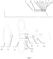
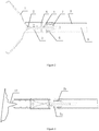
Figure 1 is a structural schematic diagram of the hemoclip of the present invention. -
Figure 2 is a schematic diagram showing an opening state of the metal clip. -
Figure 3 is a schematic diagram showing a closing state of the metal clip. -
Figure 4 is a schematic diagram showing releasing and self-locking of the metal clip. -
Figure 5 is a structural schematic diagram of the metal clip. -
Figure 6 is a structural schematic diagram of the connecting rod. -
Figure 7 is a structural schematic diagram of the releasing piece. -
Figure 8 is a structural schematic diagram of the tightening assembly. -
Figure 9 is a schematic diagram showing the electrocoagulation when electric power is supplied and the marking of the hemoclip of the present invention. -
Figure 10 is a schematic diagram showing the structure of the handle assembly when electric power is supplied. - The present invention will be further described with reference to the embodiments and the drawings hereinafter. The following embodiments are merely intended to illustrate the present invention, rather than limit the implementation scope of the present invention.
- An open-close-repeatable rotatable hemoclip for the gastrointestinal tract with electrocoagulation, as shown in
Figures 1-4 , includes a clamping assembly, a tightening assembly, an insulating outer tube assembly and a handle assembly. - The clamping assembly includes two oppositely arranged
metal clips 1. - The tightening assembly includes a
tightening tube 5, a connectingrod 4, a releasingpiece 7 and afixing base 6. Afixing pin 2 is arranged inside a front portion of the tighteningtube 5. Two symmetrical openings are arranged on a wall of a middle-lower portion of the tighteningtube 5. A wall of a portion in front of the two symmetrical openings is respectively pre-provided with a slot matched with a tail end of eachmetal clip 1. In the tighteningtube 5, the rear portions of the twometal clips 1 are connected to the connectingrod 4 through amovable pin 3. A front portion of the releasingpiece 7 and a rear portion of the tighteningtube 5 are relatively fixed in an axial direction, and relatively rotatably connected in a radial direction. A rear portion of the releasingpiece 7 and thefixing base 6 are relatively fixed in the axial direction, and relatively rotatably connected in the radial direction. The connectingrod 4 passes through thetightening tube 5 and the releasingpiece 7, successively. - The insulating outer tube assembly includes an
electric cutting wire 8, aguide tube 11 and aspring hose 9. A tail portion of theelectric cutting wire 8 is arranged inside theguide tube 11. An outer wall of the tail portion of theelectric cutting wire 8 closely contacts an inner wall of theguide tube 11. Theelectric cutting wire 8 is arranged inside thespring hose 9. A front end of theelectric cutting wire 8 is connected to a rear end of the connectingrod 4. A front end of thespring hose 9 is connected to a rear end of thefixing base 6. - The handle assembly includes a
thumb ring 16, ahandle 15, aslide ring 14, arotary wheel 10, anelectrode 13 and anelectrode holder 12. Thethumb ring 16 is arranged at a rear end of thehandle 15. Theslide ring 14 is arranged on thehandle 15. Therotary wheel 10 is arranged at a front portion of thehandle 15. Theelectrode holder 12 is arranged inside theslide ring 14. Theelectrode 13 is arranged inside theelectrode holder 12. Theelectrode holder 12 and theelectrode 13 are provided with matching threads, and the threads on theelectrode 13 are screwed into theelectrode holder 12. A rear end of thespring hose 9 is connected to a front end of thehandle 15. Theguide tube 11 deeply extends into thehandle 15 and theelectrode holder 12. Theguide tube 11 and therotary wheel 10 are relatively fixed in the radial direction and relatively slidably connected in the axial direction. Also, theguide tube 11 is tightly pressed by theelectrode 13. - The
guide tube 11 is driven to rotate with respect to thehandle 15 by rotating therotary wheel 10 so as to realize a rotation of the metal clips 1. Theslide ring 14 slides back and forth on thehandle 15 to drive theguide tube 11 to move back and forth, so as to drive the clamping assembly to reciprocate in the tighteningtube 11. The metal clips 1 are opened or closed, accordingly. When a predetermined tensile force is exerted, the connectingrod 4 and themovable pin 3 are separated, so as to drive a separation of the releasingpiece 7 and the tighteningtube 5. The tail end of eachmetal clip 1 is fixed in a preset slot of the tighteningtube 5. The metal clips 1 are closed and self-locked to realize a release of the metal clips 1. - The tightening
tube 5, the fixingbase 6, thespring hose 9, the releasingpiece 7, themetal clips 1, themovable pin 3, the connectingrod 4, theelectric cutting wire 8 and theguide tube 11 are all made of a metal material. An inner wall and an outer wall of the tighteningtube 5, an inner wall and an outer wall of the fixingbase 6, and an outer wall of thespring hose 9 are all provided with an insulating coating. The inner wall and the outer wall of the tighteningtube 5 and the fixingbase 6 are covered with the insulating coating through a brushing process or a baking process etc. The outer wall of thespring hose 9 is plastic-coated with a layer of insulating coating through the plastic coating process. The insulating coating includes insulating polymer materials such as polytetrafluoroethylene, fluorinated ethylene-propylene, ethylene-tetrafluoroethylene copolymer, polyvinylidene fluoride or silicone rubber etc. When the electric power is introduced, the insulating coating can prevent the lower half portion, except for themetal clip 1, from burning tissues by mistake, thereby avoiding or reducing touching other healthy tissues during the electrocoagulation. - As shown in
Figure 5 , the tail end of eachmetal clip 1 is provided with a bent part 1a to avoid a wobble of the clamping assembly. Ahead end 1b of eachmetal clip 1 has a quarter-spherical shape and is provided with a tooth-shaped part, and tooth-shaped parts ofmetal clips 1 are engaged with each other. A front portion of themetal clip 1 is gradually widened from front to back. A curved part 1c is arranged between the front portion and a rear portion of themetal clip 1 to increase the strength of themetal clip 1. The rear portion of themetal clip 1 is a large arc, and the strength and elasticity are increased due to the arc structure. Also, the rear portion of themetal clip 1 is provided with a hole. Themetal clip 1 is connected to themovable pin 3 through the hole. When the product is closed and passes through the endoscope, the head portion has a hemisphere shape, so as to pass through the channel of the endoscope easily and avoid damage to the product. - As shown in
Figure 6 , a front end of the connectingrod 4 is provided with alocking slot 4b, and both sides of thelocking slot 4b are provided with apin hole 4a. Thelocking slot 4b is connected to themovable pin 3 through thepin holes 4a. The twometal clips 1 are fixed in thelocking slot 4b to ensure a relative fixation when themetal clips 1 are opened repeatedly. A lower portion of a front end of the connectingrod 4 is provided with astep 4c. A rear end of the connectingrod 4 is provided with acounter bore 4d. A front end of theelectric cutting wire 8 is connected within the counter bore 4d through welding. When a predetermined tensile force is exerted, thepin hole 4a of the connectingrod 4 is broken and the connectingrod 4 is separated from themovable pin 3. While the connectingrod 4 is being retracted, a disengagement of the releasingpiece 7 and the tighteningtube 5 is driven by thestep 4c, so as to release themetal clips 1 and realize the intention of hemostasis. - As shown in
Figure 7 , the overall releasingpiece 7 has a cylindrical shape, which can reduce the friction force during the rotation. Ahead end 7a of the releasingpiece 7 consists of two projecting steps. The two projecting steps are hung on an opening of the tighteningtube 5. An axial outer diameter of a front portion of the releasingpiece 7 is matched with an inner diameter of the tail portion of the tighteningtube 5 to realize a relative fixation in the axial direction and a relative rotary connection in the radial direction. Arear portion 7b of the releasingpiece 7 is provided with a step shaft, and the step shaft is matched with a step hole in the fixingbase 6 to realize the relative fixation in the axial direction and the relative rotary connection in the radial direction to avoid a disengagement toward the head of the metal clip. When a predetermined tensile force is exerted, thehead end 7a of the releasingpiece 7 is driven by the connectingrod 4 to separate from the tighteningtube 5. - As shown in
Figure 8 , the front portion of the releasingpiece 7 and the tail portion of the tighteningtube 5 are relatively fixed in the axial direction and relatively rotatably connected in the radial direction. Therear portion 7b of the releasingpiece 7 and the fixingbase 6 are relatively fixed in the axial direction and relatively rotatably connected in the radial direction. The releasingpiece 7 overlaps with the tail portion of the tighteningtube 5 and the fixingbase 6, to form a combination of which internal parts and external parts cooperate with each other, so as to achieve the function of rotation. The overall retention length is reduced to about 12.5mm, so that the retention length inside the human body is shortened. - As shown in
Figures 9 and10 , when the marking and the electrocoagulation are required, one end of the high-frequency cable 19 is inserted into theelectrode 13, and the other end of the high-frequency cable is connected to a high-frequency electrotome. The lesion region is determined by themarks 18 according to the actual demand of the operation to help the doctor to determine the size of the lesion and the surgical method. During the implementation process, if an exudation of blood occurs, the voltage is adjusted according to the actual situation to realize a coagulation of blood on the exudation points. After the electrocoagulation is completed, if a large blood vessel is found to be bleeding, thebleeding point 17 can be closed by means of the closing function of metal clips 1. The function of repeatable opening and closing of themetal clips 1 is realized by pushing and pulling theslide ring 14. Thebleeding point 17 is pre-clamped, and after thebleeding point 17 is confirmed, themetal clip 1 is released, so that thebleeding point 17 and wound are closed. By doing so, the operation time is shortened, the patients can suffer less and medical costs are reduced.
Claims (5)
- A rotatable hemoclip assembly for the gastrointestinal tract with electrocoagulation, comprising:a clamping assembly;a tightening assembly;an insulating outer tube assembly, anda handle assembly;wherein, the clamping assembly is rotatable, can be opened and closed repeatedly and is releasable under actions of the handle assembly, the insulating outer tube assembly and the tightening assembly;the clamping assembly includes two oppositely arranged metal clips (1);the tightening assembly includes a tightening tube (5), a connecting rod (4), a releasing piece (7) and a fixing base (6);wherein, a fixing pin (2) is arranged inside a distal portion of the tightening tube (5);wherein two symmetrical openings are arranged on a wall in a proximal portion of the tightening tube;a wall of a portion distal to the two symmetrical openings is respectively pre-provided with a slot matched with a proximal end of each metal clip;in the tightening tube (5), proximal portions of the two metal clips (1) are connected to the connecting rod (4) through a movable pin (3);wherein the overall releasing piece (7) has a cylindrical shape;a distal portion (7a) of the releasing piece (7) includes two projecting steps;the two projecting steps are configured to engage with an opening of the tightening tube (5);an axial outer diameter of the distal portion (7a) of the releasing piece (7) matches with an inner diameter of a proximal portion of the tightening tube (5) and the distal portion (7a) of the releasing piece (7) and the proximal portion of the tightening tube (5) are configured to be fixed with respect to each other in the axial direction and are rotatably connected with respect to each other in a radial direction;a proximal portion (7b) of the releasing piece (7) is provided with a step shaft;the step shaft is matched with a step hole in the fixing base (6) and is configured to fix the proximal portion (7b) of the releasing piece (7) with respect to the fixing base (6) in the axial direction and is rotatably connected with respect to the fixing base (6) in the radial direction; andwhen a predetermined tensile force is exerted, the distal portion (7a) of the releasing piece (7) is configured to be driven by the connecting rod (4) to separate from the tightening tube (5);a distal part of the connecting rod (4) is disposed inside the tightening tube (5) and a proximal part of the connecting rod (4) is disposed inside the releasing piece (7), successively;the insulating outer tube assembly includes spring hose (9);a distal end of the spring hose (9) is connected to a proximal end of the fixing base (6); the handle assembly includes a thumb ring (16), a handle (15), a slide ring (14), and a rotary wheel (10); wherein, the thumb ring (16) is arranged at a proximal end of the handle (15); the slide ring (14) is arranged on the handle (15);the rotary wheel (10) is arranged at a distal end of the handle (15);a proximal end of the spring hose (9) is connected to the distal end of the handle (15);the metal clips (1) are configured to be opened or closed when the clamping assembly reciprocates; the connecting rod (4) and the movable pin (3) are configured to be separated when a predetermined tensile force is exerted a proximal end of each metal clip (1) is fixedly provided in a pre-set slot of the tightening tube (5); the metal clips (1) are configured to be closed and self-locked to realize a release of the metal clips (1); proximal ends of the two oppositely arranged metal clips (1) are provided with a bent part;the distal end of each metal clip (1) has a quarter-spherical shape; the distal end of each metal clip (1) is provided with a tooth-shaped part, and tooth-shaped parts of the metal clips (1) are engaged with each other;a distal portion of each metal clip (1) is gradually widened from a distal proximal direction;a curved part is arranged between the distal portion and a proximal portion of each metal clip (1);the proximal portion of each metal clip (1) is an arc;the proximal portion of each metal clip (1) is provided with a hole; and each metal clip (1) is connected to the movable pin (3) through the hole;characterized in that,the insulating outer tube assembly further includes an electric cutting wire (8);the electric cutting wire (8) is arranged inside the spring hose (9);a distal portion of the electric cutting wire (8) is connected to a proximal end of the connecting rod (4);and in that the rotatable hemoclip assembly further comprises an electrode (13) and an electrode holder (12) arranged inside the handle assembly;the electrode (13) is electrically connected to the clamping assembly through the insulating outer tube assembly and the tightening assembly;the insulating outer tube assembly further includes a guide tube (11);wherein, a proximal portion of the electric cutting wire (8) is arranged inside the guide tube (11);an outer wall of the proximal portion of the electric cutting wire (8) contacts an inner wall of the guide tube (11);the electrode holder (12) is arranged inside the slide ring (14);the electrode (13) is arranged inside the electrode holder (12);a proximal part of the guide tube (11) is disposed into the handle (15) and the electrode holder (12);the guide tube (11) and the rotary wheel (10) are fixed with respect to each other in the radial direction and the guide tube (11) is configured to rotate with respect to the handle by rotating the rotary wheel (10); and the guide tube (11) and the rotary wheel (10) are slidably connected with respect to each other in the axial direction;the guide tube (11) is tightly pressed by the electrode (13);the guide tube (11) is configured to rotate with respect to the handle (15) by rotating the rotary wheel (10) so as to realize a rotation of the metal clips (1);the slide ring (14) slides back and forth on the handle (15) to drive the guide tube (11) to move back and forth, so as to drive the clamping assembly to reciprocate in the tightening tube (5);the tightening tube (5), the fixing base (6), the spring hose (9), the releasing piece (7), the metal clips (1), the movable pin (3), the connecting rod (4), the electric cutting wire (8) and the guide tube (11) are made of a metal material; andan inner wall and an outer wall of the tightening tube (5), an inner wall and an outer wall of the fixing base (6), and an outer wall of the spring hose (9) are all provided with an insulating coating.
- The rotatable hemoclip assembly for the gastrointestinal tract with electrocoagulation of claim 1, wherein the electrode holder (12) and the electrode (13) are provided with matching threads, and the threads on the electrode (13) are screwed into the electrode holder (12).
- The rotatable hemoclip assembly for the gastrointestinal tract with electrocoagulation of claim 1, wherein
a distal end of the connecting rod (4) is provided with a locking slot (4b), and both sides of the locking slot (4b) are provided with a pin hole (4a); the locking slot (4b) is connected to the movable pin (3) through the pin hole (4a); the two metal clips (1) are fixed in the locking slot (4b);
a distal portion of the distal end of the connecting rod (4) is provided with a step (4c); the proximal end of the connecting rod (4) is provided with a counter bore (4d); the distal end of the electric cutting wire (8) is connected within the counter bore (4d); the pin hole (4a) of the connecting rod (4) is configured to be broken and the connecting rod (4) is configured to be separated from the movable pin (3) under the effect of the predetermined tensile force. - The rotatable hemoclip assembly for the gastrointestinal tract with electrocoagulation of claim 1, wherein
the inner wall and the outer wall of the tightening tube (5) and the inner wall and the outer wall of the fixing base (6) are covered with the insulating coating through a brushing process or a baking process; and
the outer wall of the spring hose (9) is plastic-coated with a layer of insulating coating through the plastic coating process. - The open-close-repeatable rotatable hemoclip assembly for the gastrointestinal tract with electrocoagulation of claim 4, wherein
the insulating coating is selected from the group consisting of polytetrafluoroethylene, fluorinated ethylene-propylene, ethylene-tetrafluoroethylene copolymer, polyvinylidene fluoride and silicone rubber.
Applications Claiming Priority (2)
| Application Number | Priority Date | Filing Date | Title |
|---|---|---|---|
| CN201611004338.XA CN106473805B (en) | 2016-11-15 | 2016-11-15 | Digestive tract hemostatic clamp with electrification and repeated opening and closing and rotating functions |
| CN201611004337.5A CN106491176A (en) | 2016-11-15 | 2016-11-15 | One kind is rotatable to be repeated to be opened and closed hemostatic clamp |
Publications (2)
| Publication Number | Publication Date |
|---|---|
| EP3320863A1 EP3320863A1 (en) | 2018-05-16 |
| EP3320863B1 true EP3320863B1 (en) | 2021-03-31 |
Family
ID=60413056
Family Applications (1)
| Application Number | Title | Priority Date | Filing Date |
|---|---|---|---|
| EP17201288.2A Active EP3320863B1 (en) | 2016-11-15 | 2017-11-13 | Rotatable hemoclip for repeatable opening and closing for the gastrointestinal tract with electrocoagulation |
Country Status (2)
| Country | Link |
|---|---|
| US (1) | US10610234B2 (en) |
| EP (1) | EP3320863B1 (en) |
Families Citing this family (10)
| Publication number | Priority date | Publication date | Assignee | Title |
|---|---|---|---|---|
| CN108969043B (en) * | 2018-08-17 | 2024-05-28 | 刘建强 | Releasable alimentary canal incision closure device |
| EP3876814A4 (en) * | 2018-11-08 | 2022-08-17 | Cedars-Sinai Medical Center | A novel tool for hemostasis and tissue approximation |
| US12490991B2 (en) | 2020-05-08 | 2025-12-09 | Cedars-Sinai Medical Center | Systems and methods for hemoclip deployment |
| CN111904484B (en) * | 2020-08-31 | 2024-07-30 | 江苏康宏医疗科技有限公司 | Soft tissue clamp reducing round wire spring tube capable of being rotated and repeatedly opened and closed |
| CN114680992B (en) * | 2020-12-25 | 2025-03-18 | 常州乐奥医疗科技股份有限公司 | Clip assembly for hemostatic clip and hemostatic clip |
| CN112826586B (en) * | 2021-03-10 | 2022-03-22 | 西安医学院第二附属医院 | Electrocoagulation forceps for gynecological and obstetrical operations |
| CN113907870B (en) * | 2021-11-06 | 2023-08-15 | 嘉兴市中医医院 | Hemostatic auxiliary electrocoagulation biopsy forceps |
| CN114431952B (en) * | 2022-01-23 | 2023-05-16 | 吉林大学第一医院 | Multifunctional clinical hemostat for hepatobiliary and pancreatic surgery |
| CN115944347B (en) * | 2023-01-04 | 2026-04-24 | 浙江首鼎医学科技有限公司 | A hemostatic clip with a split structure |
| CN120203702B (en) * | 2025-05-28 | 2025-08-19 | 四川大学华西医院 | Inferior vena cava root blood vessel dissection separating forceps for liver surgery |
Citations (1)
| Publication number | Priority date | Publication date | Assignee | Title |
|---|---|---|---|---|
| CN204909551U (en) * | 2015-07-28 | 2015-12-30 | 杭州安杰思医学科技有限公司 | Rotatable hemostasis is pressed from both sides |
Family Cites Families (10)
| Publication number | Priority date | Publication date | Assignee | Title |
|---|---|---|---|---|
| CA2103773C (en) | 1992-08-19 | 1998-11-03 | David T. Green | Handle for endoscopic surgical instruments and jaw structure |
| DE4323584A1 (en) * | 1993-07-14 | 1995-01-19 | Delma Elektro Med App | Detachable medical instrument |
| DE69517153T2 (en) * | 1994-11-02 | 2001-02-01 | Olympus Optical Co., Ltd. | INSTRUMENT WORKING WITH ENDOSCOPE |
| DE19512640C2 (en) * | 1995-04-05 | 1997-01-30 | Winter & Ibe Olympus | Surgical endoscope instrument with HF working electrode |
| JP2000254143A (en) | 1999-03-08 | 2000-09-19 | Asahi Optical Co Ltd | Endoscope hemostatic clip device |
| US6793664B2 (en) * | 2000-06-19 | 2004-09-21 | Image-Guided Neurologics | System and method of minimally-invasive exovascular aneurysm treatment |
| JP3989170B2 (en) * | 2000-10-05 | 2007-10-10 | オリンパス株式会社 | High frequency treatment tool |
| JP3934458B2 (en) * | 2002-04-09 | 2007-06-20 | ペンタックス株式会社 | Bipolar high-frequency hemostatic forceps for endoscope |
| JP4137931B2 (en) * | 2005-10-28 | 2008-08-20 | オリンパスメディカルシステムズ株式会社 | Endoscopic treatment tool |
| US8585716B2 (en) * | 2006-12-13 | 2013-11-19 | Boston Scientific Scimed, Inc. | Apparatus for applying hemostatic clips |
-
2017
- 2017-11-13 US US15/810,155 patent/US10610234B2/en active Active
- 2017-11-13 EP EP17201288.2A patent/EP3320863B1/en active Active
Patent Citations (1)
| Publication number | Priority date | Publication date | Assignee | Title |
|---|---|---|---|---|
| CN204909551U (en) * | 2015-07-28 | 2015-12-30 | 杭州安杰思医学科技有限公司 | Rotatable hemostasis is pressed from both sides |
Also Published As
| Publication number | Publication date |
|---|---|
| EP3320863A1 (en) | 2018-05-16 |
| US20180132855A1 (en) | 2018-05-17 |
| US10610234B2 (en) | 2020-04-07 |
Similar Documents
| Publication | Publication Date | Title |
|---|---|---|
| US10610234B2 (en) | Open-close-repeatable rotatable hemoclip for the gastrointestinal tract with electrocoagulation | |
| JP7496158B2 (en) | Electrosurgical Cutting Instruments | |
| KR101283717B1 (en) | Treatment instrument for endoscope | |
| US11324544B2 (en) | Medical instrument | |
| JP5563485B2 (en) | Polyp removal device and method of use | |
| EP3081174B1 (en) | Hemostatic clip | |
| AU2019260152B2 (en) | Multifunctional high-frequency electric knife | |
| CN106473805B (en) | Digestive tract hemostatic clamp with electrification and repeated opening and closing and rotating functions | |
| US20090131933A1 (en) | Bipolar forceps | |
| US20090131932A1 (en) | Bipolar forceps having a cutting element | |
| JPH11192205A (en) | Drainage tube indwelling device for endoscope | |
| CN106572883A (en) | Electrodes for surgical instruments and methods of use | |
| CN206443757U (en) | A kind of alimentary canal hemostatic clamp that folding and rotation are repeated with coagulation | |
| JP2007117405A (en) | Endoscopic treatment tool | |
| JP7732673B2 (en) | Electrosurgical cutting instruments | |
| CN108992140A (en) | Scissor electric knife under a kind of multi-functional endoscope | |
| JP2003220074A (en) | Medical apparatus | |
| US10548626B2 (en) | Endoscopic tissue manipulation tool | |
| CN109893239A (en) | The surgical device and system based on energy removed convenient for tissue | |
| CN121987326A (en) | Multifunctional puncture suspension instrument | |
| HK1261009A1 (en) | A multifunctional high-frequency electrosurgical cutting knife |
Legal Events
| Date | Code | Title | Description |
|---|---|---|---|
| PUAI | Public reference made under article 153(3) epc to a published international application that has entered the european phase |
Free format text: ORIGINAL CODE: 0009012 |
|
| STAA | Information on the status of an ep patent application or granted ep patent |
Free format text: STATUS: REQUEST FOR EXAMINATION WAS MADE |
|
| 17P | Request for examination filed |
Effective date: 20171113 |
|
| AK | Designated contracting states |
Kind code of ref document: A1 Designated state(s): AL AT BE BG CH CY CZ DE DK EE ES FI FR GB GR HR HU IE IS IT LI LT LU LV MC MK MT NL NO PL PT RO RS SE SI SK SM TR |
|
| AX | Request for extension of the european patent |
Extension state: BA ME |
|
| STAA | Information on the status of an ep patent application or granted ep patent |
Free format text: STATUS: EXAMINATION IS IN PROGRESS |
|
| 17Q | First examination report despatched |
Effective date: 20191002 |
|
| GRAP | Despatch of communication of intention to grant a patent |
Free format text: ORIGINAL CODE: EPIDOSNIGR1 |
|
| STAA | Information on the status of an ep patent application or granted ep patent |
Free format text: STATUS: GRANT OF PATENT IS INTENDED |
|
| RIC1 | Information provided on ipc code assigned before grant |
Ipc: A61B 18/00 20060101ALN20201028BHEP Ipc: A61B 17/12 20060101ALN20201028BHEP Ipc: A61B 18/12 20060101ALI20201028BHEP Ipc: A61B 17/122 20060101AFI20201028BHEP Ipc: A61B 17/128 20060101ALI20201028BHEP Ipc: A61B 18/14 20060101ALI20201028BHEP Ipc: A61B 17/00 20060101ALN20201028BHEP |
|
| INTG | Intention to grant announced |
Effective date: 20201125 |
|
| RAP1 | Party data changed (applicant data changed or rights of an application transferred) |
Owner name: ZHEJIANG CHUANGXIANG MEDICAL TECHNOLOGY CO., LTD. |
|
| GRAS | Grant fee paid |
Free format text: ORIGINAL CODE: EPIDOSNIGR3 |
|
| GRAA | (expected) grant |
Free format text: ORIGINAL CODE: 0009210 |
|
| STAA | Information on the status of an ep patent application or granted ep patent |
Free format text: STATUS: THE PATENT HAS BEEN GRANTED |
|
| AK | Designated contracting states |
Kind code of ref document: B1 Designated state(s): AL AT BE BG CH CY CZ DE DK EE ES FI FR GB GR HR HU IE IS IT LI LT LU LV MC MK MT NL NO PL PT RO RS SE SI SK SM TR |
|
| REG | Reference to a national code |
Ref country code: GB Ref legal event code: FG4D Ref country code: CH Ref legal event code: EP |
|
| REG | Reference to a national code |
Ref country code: AT Ref legal event code: REF Ref document number: 1376051 Country of ref document: AT Kind code of ref document: T Effective date: 20210415 |
|
| REG | Reference to a national code |
Ref country code: DE Ref legal event code: R096 Ref document number: 602017035584 Country of ref document: DE |
|
| REG | Reference to a national code |
Ref country code: IE Ref legal event code: FG4D |
|
| REG | Reference to a national code |
Ref country code: LT Ref legal event code: MG9D |
|
| PG25 | Lapsed in a contracting state [announced via postgrant information from national office to epo] |
Ref country code: BG Free format text: LAPSE BECAUSE OF FAILURE TO SUBMIT A TRANSLATION OF THE DESCRIPTION OR TO PAY THE FEE WITHIN THE PRESCRIBED TIME-LIMIT Effective date: 20210630 Ref country code: NO Free format text: LAPSE BECAUSE OF FAILURE TO SUBMIT A TRANSLATION OF THE DESCRIPTION OR TO PAY THE FEE WITHIN THE PRESCRIBED TIME-LIMIT Effective date: 20210630 Ref country code: FI Free format text: LAPSE BECAUSE OF FAILURE TO SUBMIT A TRANSLATION OF THE DESCRIPTION OR TO PAY THE FEE WITHIN THE PRESCRIBED TIME-LIMIT Effective date: 20210331 Ref country code: HR Free format text: LAPSE BECAUSE OF FAILURE TO SUBMIT A TRANSLATION OF THE DESCRIPTION OR TO PAY THE FEE WITHIN THE PRESCRIBED TIME-LIMIT Effective date: 20210331 |
|
| PG25 | Lapsed in a contracting state [announced via postgrant information from national office to epo] |
Ref country code: RS Free format text: LAPSE BECAUSE OF FAILURE TO SUBMIT A TRANSLATION OF THE DESCRIPTION OR TO PAY THE FEE WITHIN THE PRESCRIBED TIME-LIMIT Effective date: 20210331 Ref country code: LV Free format text: LAPSE BECAUSE OF FAILURE TO SUBMIT A TRANSLATION OF THE DESCRIPTION OR TO PAY THE FEE WITHIN THE PRESCRIBED TIME-LIMIT Effective date: 20210331 Ref country code: SE Free format text: LAPSE BECAUSE OF FAILURE TO SUBMIT A TRANSLATION OF THE DESCRIPTION OR TO PAY THE FEE WITHIN THE PRESCRIBED TIME-LIMIT Effective date: 20210331 |
|
| REG | Reference to a national code |
Ref country code: NL Ref legal event code: MP Effective date: 20210331 |
|
| REG | Reference to a national code |
Ref country code: AT Ref legal event code: MK05 Ref document number: 1376051 Country of ref document: AT Kind code of ref document: T Effective date: 20210331 |
|
| PG25 | Lapsed in a contracting state [announced via postgrant information from national office to epo] |
Ref country code: CZ Free format text: LAPSE BECAUSE OF FAILURE TO SUBMIT A TRANSLATION OF THE DESCRIPTION OR TO PAY THE FEE WITHIN THE PRESCRIBED TIME-LIMIT Effective date: 20210331 Ref country code: EE Free format text: LAPSE BECAUSE OF FAILURE TO SUBMIT A TRANSLATION OF THE DESCRIPTION OR TO PAY THE FEE WITHIN THE PRESCRIBED TIME-LIMIT Effective date: 20210331 Ref country code: LT Free format text: LAPSE BECAUSE OF FAILURE TO SUBMIT A TRANSLATION OF THE DESCRIPTION OR TO PAY THE FEE WITHIN THE PRESCRIBED TIME-LIMIT Effective date: 20210331 Ref country code: SM Free format text: LAPSE BECAUSE OF FAILURE TO SUBMIT A TRANSLATION OF THE DESCRIPTION OR TO PAY THE FEE WITHIN THE PRESCRIBED TIME-LIMIT Effective date: 20210331 Ref country code: NL Free format text: LAPSE BECAUSE OF FAILURE TO SUBMIT A TRANSLATION OF THE DESCRIPTION OR TO PAY THE FEE WITHIN THE PRESCRIBED TIME-LIMIT Effective date: 20210331 Ref country code: AT Free format text: LAPSE BECAUSE OF FAILURE TO SUBMIT A TRANSLATION OF THE DESCRIPTION OR TO PAY THE FEE WITHIN THE PRESCRIBED TIME-LIMIT Effective date: 20210331 |
|
| PG25 | Lapsed in a contracting state [announced via postgrant information from national office to epo] |
Ref country code: IS Free format text: LAPSE BECAUSE OF FAILURE TO SUBMIT A TRANSLATION OF THE DESCRIPTION OR TO PAY THE FEE WITHIN THE PRESCRIBED TIME-LIMIT Effective date: 20210731 Ref country code: PT Free format text: LAPSE BECAUSE OF FAILURE TO SUBMIT A TRANSLATION OF THE DESCRIPTION OR TO PAY THE FEE WITHIN THE PRESCRIBED TIME-LIMIT Effective date: 20210802 Ref country code: PL Free format text: LAPSE BECAUSE OF FAILURE TO SUBMIT A TRANSLATION OF THE DESCRIPTION OR TO PAY THE FEE WITHIN THE PRESCRIBED TIME-LIMIT Effective date: 20210331 Ref country code: RO Free format text: LAPSE BECAUSE OF FAILURE TO SUBMIT A TRANSLATION OF THE DESCRIPTION OR TO PAY THE FEE WITHIN THE PRESCRIBED TIME-LIMIT Effective date: 20210331 Ref country code: SK Free format text: LAPSE BECAUSE OF FAILURE TO SUBMIT A TRANSLATION OF THE DESCRIPTION OR TO PAY THE FEE WITHIN THE PRESCRIBED TIME-LIMIT Effective date: 20210331 |
|
| REG | Reference to a national code |
Ref country code: DE Ref legal event code: R097 Ref document number: 602017035584 Country of ref document: DE |
|
| PG25 | Lapsed in a contracting state [announced via postgrant information from national office to epo] |
Ref country code: ES Free format text: LAPSE BECAUSE OF FAILURE TO SUBMIT A TRANSLATION OF THE DESCRIPTION OR TO PAY THE FEE WITHIN THE PRESCRIBED TIME-LIMIT Effective date: 20210331 Ref country code: DK Free format text: LAPSE BECAUSE OF FAILURE TO SUBMIT A TRANSLATION OF THE DESCRIPTION OR TO PAY THE FEE WITHIN THE PRESCRIBED TIME-LIMIT Effective date: 20210331 Ref country code: AL Free format text: LAPSE BECAUSE OF FAILURE TO SUBMIT A TRANSLATION OF THE DESCRIPTION OR TO PAY THE FEE WITHIN THE PRESCRIBED TIME-LIMIT Effective date: 20210331 |
|
| PLBE | No opposition filed within time limit |
Free format text: ORIGINAL CODE: 0009261 |
|
| STAA | Information on the status of an ep patent application or granted ep patent |
Free format text: STATUS: NO OPPOSITION FILED WITHIN TIME LIMIT |
|
| 26N | No opposition filed |
Effective date: 20220104 |
|
| PG25 | Lapsed in a contracting state [announced via postgrant information from national office to epo] |
Ref country code: IS Free format text: LAPSE BECAUSE OF FAILURE TO SUBMIT A TRANSLATION OF THE DESCRIPTION OR TO PAY THE FEE WITHIN THE PRESCRIBED TIME-LIMIT Effective date: 20210731 |
|
| PG25 | Lapsed in a contracting state [announced via postgrant information from national office to epo] |
Ref country code: MC Free format text: LAPSE BECAUSE OF FAILURE TO SUBMIT A TRANSLATION OF THE DESCRIPTION OR TO PAY THE FEE WITHIN THE PRESCRIBED TIME-LIMIT Effective date: 20210331 |
|
| REG | Reference to a national code |
Ref country code: CH Ref legal event code: PL |
|
| PG25 | Lapsed in a contracting state [announced via postgrant information from national office to epo] |
Ref country code: LU Free format text: LAPSE BECAUSE OF NON-PAYMENT OF DUE FEES Effective date: 20211113 Ref country code: IT Free format text: LAPSE BECAUSE OF FAILURE TO SUBMIT A TRANSLATION OF THE DESCRIPTION OR TO PAY THE FEE WITHIN THE PRESCRIBED TIME-LIMIT Effective date: 20210331 Ref country code: BE Free format text: LAPSE BECAUSE OF NON-PAYMENT OF DUE FEES Effective date: 20211130 |
|
| REG | Reference to a national code |
Ref country code: BE Ref legal event code: MM Effective date: 20211130 |
|
| PG25 | Lapsed in a contracting state [announced via postgrant information from national office to epo] |
Ref country code: IE Free format text: LAPSE BECAUSE OF NON-PAYMENT OF DUE FEES Effective date: 20211113 |
|
| PG25 | Lapsed in a contracting state [announced via postgrant information from national office to epo] |
Ref country code: HU Free format text: LAPSE BECAUSE OF FAILURE TO SUBMIT A TRANSLATION OF THE DESCRIPTION OR TO PAY THE FEE WITHIN THE PRESCRIBED TIME-LIMIT; INVALID AB INITIO Effective date: 20171113 |
|
| PG25 | Lapsed in a contracting state [announced via postgrant information from national office to epo] |
Ref country code: CY Free format text: LAPSE BECAUSE OF FAILURE TO SUBMIT A TRANSLATION OF THE DESCRIPTION OR TO PAY THE FEE WITHIN THE PRESCRIBED TIME-LIMIT Effective date: 20210331 |
|
| PG25 | Lapsed in a contracting state [announced via postgrant information from national office to epo] |
Ref country code: LI Free format text: LAPSE BECAUSE OF NON-PAYMENT OF DUE FEES Effective date: 20220701 Ref country code: GR Free format text: LAPSE BECAUSE OF FAILURE TO SUBMIT A TRANSLATION OF THE DESCRIPTION OR TO PAY THE FEE WITHIN THE PRESCRIBED TIME-LIMIT Effective date: 20210331 Ref country code: CH Free format text: LAPSE BECAUSE OF NON-PAYMENT OF DUE FEES Effective date: 20220701 |
|
| PG25 | Lapsed in a contracting state [announced via postgrant information from national office to epo] |
Ref country code: MK Free format text: LAPSE BECAUSE OF FAILURE TO SUBMIT A TRANSLATION OF THE DESCRIPTION OR TO PAY THE FEE WITHIN THE PRESCRIBED TIME-LIMIT Effective date: 20210331 |
|
| PG25 | Lapsed in a contracting state [announced via postgrant information from national office to epo] |
Ref country code: TR Free format text: LAPSE BECAUSE OF FAILURE TO SUBMIT A TRANSLATION OF THE DESCRIPTION OR TO PAY THE FEE WITHIN THE PRESCRIBED TIME-LIMIT Effective date: 20210331 |
|
| PG25 | Lapsed in a contracting state [announced via postgrant information from national office to epo] |
Ref country code: MT Free format text: LAPSE BECAUSE OF FAILURE TO SUBMIT A TRANSLATION OF THE DESCRIPTION OR TO PAY THE FEE WITHIN THE PRESCRIBED TIME-LIMIT Effective date: 20210331 |
|
| PGFP | Annual fee paid to national office [announced via postgrant information from national office to epo] |
Ref country code: DE Payment date: 20251117 Year of fee payment: 9 |
|
| PGFP | Annual fee paid to national office [announced via postgrant information from national office to epo] |
Ref country code: GB Payment date: 20251126 Year of fee payment: 9 |
|
| PGFP | Annual fee paid to national office [announced via postgrant information from national office to epo] |
Ref country code: FR Payment date: 20251127 Year of fee payment: 9 |