EP3320520B1 - Apparatus, system and method for assisting in providing a diagnosis of a medical condition of a mammal brain as well a computer readable medium comprising a program for carrying out the method - Google Patents
Apparatus, system and method for assisting in providing a diagnosis of a medical condition of a mammal brain as well a computer readable medium comprising a program for carrying out the method Download PDFInfo
- Publication number
- EP3320520B1 EP3320520B1 EP16751029.6A EP16751029A EP3320520B1 EP 3320520 B1 EP3320520 B1 EP 3320520B1 EP 16751029 A EP16751029 A EP 16751029A EP 3320520 B1 EP3320520 B1 EP 3320520B1
- Authority
- EP
- European Patent Office
- Prior art keywords
- value
- brain
- pair
- indicative
- determined
- Prior art date
- Legal status (The legal status is an assumption and is not a legal conclusion. Google has not performed a legal analysis and makes no representation as to the accuracy of the status listed.)
- Active
Links
Images






Classifications
-
- A—HUMAN NECESSITIES
- A61—MEDICAL OR VETERINARY SCIENCE; HYGIENE
- A61B—DIAGNOSIS; SURGERY; IDENTIFICATION
- A61B5/00—Measuring for diagnostic purposes; Identification of persons
- A61B5/74—Details of notification to user or communication with user or patient; User input means
- A61B5/742—Details of notification to user or communication with user or patient; User input means using visual displays
- A61B5/7435—Displaying user selection data, e.g. icons in a graphical user interface
-
- G—PHYSICS
- G06—COMPUTING OR CALCULATING; COUNTING
- G06T—IMAGE DATA PROCESSING OR GENERATION, IN GENERAL
- G06T7/00—Image analysis
- G06T7/0002—Inspection of images, e.g. flaw detection
- G06T7/0012—Biomedical image inspection
-
- A—HUMAN NECESSITIES
- A61—MEDICAL OR VETERINARY SCIENCE; HYGIENE
- A61B—DIAGNOSIS; SURGERY; IDENTIFICATION
- A61B5/00—Measuring for diagnostic purposes; Identification of persons
- A61B5/0033—Features or image-related aspects of imaging apparatus, e.g. for MRI, optical tomography or impedance tomography apparatus; Arrangements of imaging apparatus in a room
- A61B5/004—Features or image-related aspects of imaging apparatus, e.g. for MRI, optical tomography or impedance tomography apparatus; Arrangements of imaging apparatus in a room adapted for image acquisition of a particular organ or body part
- A61B5/0042—Features or image-related aspects of imaging apparatus, e.g. for MRI, optical tomography or impedance tomography apparatus; Arrangements of imaging apparatus in a room adapted for image acquisition of a particular organ or body part for the brain
-
- A—HUMAN NECESSITIES
- A61—MEDICAL OR VETERINARY SCIENCE; HYGIENE
- A61B—DIAGNOSIS; SURGERY; IDENTIFICATION
- A61B6/00—Apparatus or devices for radiation diagnosis; Apparatus or devices for radiation diagnosis combined with radiation therapy equipment
- A61B6/02—Arrangements for diagnosis sequentially in different planes; Stereoscopic radiation diagnosis
- A61B6/03—Computed tomography [CT]
- A61B6/032—Transmission computed tomography [CT]
-
- A—HUMAN NECESSITIES
- A61—MEDICAL OR VETERINARY SCIENCE; HYGIENE
- A61B—DIAGNOSIS; SURGERY; IDENTIFICATION
- A61B6/00—Apparatus or devices for radiation diagnosis; Apparatus or devices for radiation diagnosis combined with radiation therapy equipment
- A61B6/46—Arrangements for interfacing with the operator or the patient
- A61B6/461—Displaying means of special interest
- A61B6/463—Displaying means of special interest characterised by displaying multiple images or images and diagnostic data on one display
-
- A—HUMAN NECESSITIES
- A61—MEDICAL OR VETERINARY SCIENCE; HYGIENE
- A61B—DIAGNOSIS; SURGERY; IDENTIFICATION
- A61B6/00—Apparatus or devices for radiation diagnosis; Apparatus or devices for radiation diagnosis combined with radiation therapy equipment
- A61B6/46—Arrangements for interfacing with the operator or the patient
- A61B6/461—Displaying means of special interest
- A61B6/465—Displaying means of special interest adapted to display user selection data, e.g. graphical user interface, icons or menus
-
- G—PHYSICS
- G06—COMPUTING OR CALCULATING; COUNTING
- G06T—IMAGE DATA PROCESSING OR GENERATION, IN GENERAL
- G06T7/00—Image analysis
- G06T7/0002—Inspection of images, e.g. flaw detection
- G06T7/0012—Biomedical image inspection
- G06T7/0014—Biomedical image inspection using an image reference approach
-
- G—PHYSICS
- G06—COMPUTING OR CALCULATING; COUNTING
- G06T—IMAGE DATA PROCESSING OR GENERATION, IN GENERAL
- G06T7/00—Image analysis
- G06T7/60—Analysis of geometric attributes
- G06T7/68—Analysis of geometric attributes of symmetry
-
- G—PHYSICS
- G06—COMPUTING OR CALCULATING; COUNTING
- G06T—IMAGE DATA PROCESSING OR GENERATION, IN GENERAL
- G06T11/00—Two-dimensional [2D] image generation
- G06T11/20—Drawing from basic elements
- G06T11/26—Drawing of charts or graphs
-
- G—PHYSICS
- G06—COMPUTING OR CALCULATING; COUNTING
- G06T—IMAGE DATA PROCESSING OR GENERATION, IN GENERAL
- G06T2207/00—Indexing scheme for image analysis or image enhancement
- G06T2207/10—Image acquisition modality
- G06T2207/10072—Tomographic images
- G06T2207/10081—Computed x-ray tomography [CT]
-
- G—PHYSICS
- G06—COMPUTING OR CALCULATING; COUNTING
- G06T—IMAGE DATA PROCESSING OR GENERATION, IN GENERAL
- G06T2207/00—Indexing scheme for image analysis or image enhancement
- G06T2207/10—Image acquisition modality
- G06T2207/10072—Tomographic images
- G06T2207/10088—Magnetic resonance imaging [MRI]
-
- G—PHYSICS
- G06—COMPUTING OR CALCULATING; COUNTING
- G06T—IMAGE DATA PROCESSING OR GENERATION, IN GENERAL
- G06T2207/00—Indexing scheme for image analysis or image enhancement
- G06T2207/20—Special algorithmic details
- G06T2207/20076—Probabilistic image processing
-
- G—PHYSICS
- G06—COMPUTING OR CALCULATING; COUNTING
- G06T—IMAGE DATA PROCESSING OR GENERATION, IN GENERAL
- G06T2207/00—Indexing scheme for image analysis or image enhancement
- G06T2207/20—Special algorithmic details
- G06T2207/20081—Training; Learning
-
- G—PHYSICS
- G06—COMPUTING OR CALCULATING; COUNTING
- G06T—IMAGE DATA PROCESSING OR GENERATION, IN GENERAL
- G06T2207/00—Indexing scheme for image analysis or image enhancement
- G06T2207/30—Subject of image; Context of image processing
- G06T2207/30004—Biomedical image processing
- G06T2207/30016—Brain
Definitions
- WO2008069762 discloses a method for identifying a pathological region within a scan.
- the scan may be of any kind in which there is difference of intensity between normal and pathological regions. It particularly relates to a method for identifying brain scan slices that may include an acute ischemic stroke region, a method for distinguishing a brain hemisphere having the stroke region, and systems and software for performing the methods.
- the method analyses the intensity distribution of pixel values obtained as a result from the scan by a procedure including the following steps.
- the value P b +20 - P b is denoted the "bright band difference", referring to the intensity difference between the top and bottom end of the "bright band” of the histogram and the value P d +20 - P d is denoted the “dark band difference” referring to the intensity difference between the top and bottom end of the "dark band” of the histogram.
- the difference obtained between the value of the parameter for the left hemisphere and the right hemisphere in a same slice are used as an indication of the presence of a pathological condition.
- WO 2011/142725 A1 discloses the analysis of brain functionality by comparing intensity distributions between brain hemispheres. Apart from intensity distributions, other characteristics include numerical parameters indicative of the characteristics of a body region such as percentiles and percentile ratios indicative for said intensity distributions.
- It is a still further object of the present invention to provided a computer accessible medium comprising a computer program with instructions for causing a programmable computer to execute each of the steps of the improved method.
- an apparatus for assisting in providing a diagnosis of a medical condition of a mammal brain, the brain having a first and a second part.
- the apparatus includes an input facility, a conversion facility, and an output device.
- the apparatus is configured and arranged such that in an operational mode of the apparatus the input facility receives at least one pair of values and at least one pair of reference values.
- the at least one pair of values includes:
- the at least one pair of reference values includes:
- the conversion facility determines a third value, indicating the cumulative probability of said first value according to said first reference data and a fourth value, indicating the cumulative probability of said second value according to said second reference data.
- the output device generates a human accessible output signal which is indicative for a substantially monotonically increasing function of a difference between the third and the fourth value.
- the separate device may be coupled with a scanning device, such as an MRI scanner arranged in the neighborhood of the separate device that is equipped with image analysis means to provide the first value and the second value of the at least one pair of values by analysis of image data obtained with the scanning device.
- a scanning device with image analysis means may also have been used to gather the first and second reference data and have a storage space for storing this reference data to be provided to the separate device.
- a system according to claim 12 comprises an apparatus according to the first embodiment and that further comprises one or more of a scanning device with image analysis functionality for determining the first value and the second value; and a storage facility for storing and providing said first and said second reference data.
- a method according to claim 13 for assisting a medical professional in providing a diagnosis of a medical condition of a mammal brain, the brain having a first and a second part.
- the at least one pair of values includes:
- the first and the second part are the left and the right hemisphere of the brain. Nevertheless the parts from which the portions to be compared are selected may also be other parts. Also the comparison may involve a combination of mutually corresponding portions from the left and the right hemisphere of the brain and a mutually corresponding portions from a pair of otherwise defined parts of the brain.
- the inventive apparatus and method facilitates a medical specialist in establishing a diagnosis of a subject.
- AD Alzheimer disease
- FDD fronto-temporal dementia
- Atrophy of the frontal and temporal regions in case of fronto-temporal dementia (FTD) often occurs asymmetrically.
- Corticobasal Degeneration tends to occur in an asymmetric manner.
- Lewy Body dementia typically is visible as a substantially symmetric atrophy.
- FIG. 1 schematically shows an apparatus 10 for assisting in providing a diagnosis of a brain characteristic of a mammal brain.
- the apparatus 10 includes an input facility 12, a conversion facility 14L, 14R, and an output device 16.
- the apparatus is configured and arranged such that in an operational mode of the apparatus the input facility 12 receives a pair of values VL,VR and a pair of reference values VRL, VRR.
- a portion of the left part of the brain may comprise one of the left frontal lobe, left parietal lobe, left occipital lobe, left temporal lobe, left limbic lobe, and left hippocampus.
- the cortex can be sub-divided into 49 "parcellation units" (PUs), which are mutually bounded by a sulcus, i.e. a depression or fissure between the folds of cortical grey matter (gyri).
- PUs parcellation units
- a corresponding portion of the right part of the brain is that part which is symmetrically arranged with respect to the portion of the left part of the brain that is considered.
- the corresponding portion of the left frontal lobe is the right frontal lobe.
- a brain characteristic may be any feature which can describe (phenotype) the brain. Examples are
- the pair of reference values includes first and second reference data.
- the first reference data VRL indicates a cumulative distribution of the first value for the portion, e.g. for the left frontal lobe, in a reference population.
- the second reference data VRR indicates a cumulative distribution of the second value for the corresponding portion, e.g. the right frontal lobe, in the reference population.
- the conversion facility 14L, 14R determines a third value VPL that indicates the cumulative probability of the first value VL according to the first reference data VRL.
- the conversion facility 14L, 14R further determines a fourth value VPR that indicates the cumulative probability of the second value VR according to the second reference data VRR.
- the output device 16 generates a human accessible output signal SH which is indicative for a substantially monotonically increasing function of a difference between the third and the fourth value VPL, VPR.
- the apparatus 10 is part of a system 50, which further comprises one or more of:
- the conversion facility 14L, 14R may be a single facility that applies the conversion to both the first value VL and the second value VR.
- the scanning device 52L, 52R with image analysis functionality may be a single facility and the a storage facility 54L, 54R may be a single facility.
- FIG. 2 schematically shows a method for assisting in providing a diagnosis of a medical condition of a mammal brain, the brain having a left and a right part.
- a first step S1 of the method of FIG. 2 at least one pair of values VL,VR as well as at least one pair of reference values VRL,VRR is received.
- the at least one pair of values includes a first value VL indicative of a brain characteristic of a portion of the left part of the brain for a point in time and a second value VR indicative of a brain characteristic of a corresponding portion of the right part of the brain for that point in time.
- the at least one pair of reference values includes first reference data VRL indicative for a cumulative distribution of the value for said portion in a reference population and second reference VRR data indicative for a cumulative distribution of the second value for the corresponding portion in the reference population.
- a third step S3 is performed, wherein a human accessible output signal SH is generated that is indicative for a substantially monotonically increasing function of a difference between the third and the fourth value.
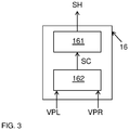
- FIG. 3 shows part of an embodiment of the apparatus.
- the output device 16 comprises a display unit 161 and a control unit 162 that generates control signals SC for the display unit.
- the image rendered by the output device 16 provides, in a single overview, information on the extent of asymmetry for various brain characteristics in terms of their distribution known from the reference population. This can be used as objective, quantitative information to support the diagnosis of a wide range of neurological diseases as is set out in more detail below.
- the values VL, VR, VPL, VPR indicate a volume of a particular brain portion.
- FIG. 4 shows two further icons ICw1 and ICw2.
- ICw1 indicates the cumulative probability of a value determined for the combined volume of the grey and white matter tissue, according to reference data indicating the distribution of that value for a reference population.
- ICw2 indicates the cumulative probability of a value determined for the whole brain white matter lesion volume, according to reference data indicating the distribution of that value for a reference population.
- MRI images were obtained from each of the 5000 reference subjects as shown in step S1 using a1.5 T MRI system (General Electric Healthcare, Milwaukee, Wisconsin).
- the brain characteristic value for the corresponding particular portion of the right brain hemisphere.
- the particular portions considered in this case are the mutually corresponding left and right frontal lobe, left and right temporal lobe, left and right parietal lobe, left and right occipital lobe, and the left and right hippocampus.
- the comparison is made for "whole brain tissue" (grey and white matter volume) and the whole brain white matter lesion volume.
- the lower and upper boundary of the boxes respectively indicates the percentiles 25 and 75.
- the whiskers indicate the percentiles corresponding to 1.5 times the interquartile range (IQR).
- the medical specialist observes that the third and the fourth values the frontal lobes are very low i.e. 10% and 25% as compared to the reference group. In view of the low value indicated for both sides the suspicion that the person suffers from Mild Cognitive Impairment is reinforced.
Landscapes
- Engineering & Computer Science (AREA)
- Health & Medical Sciences (AREA)
- Life Sciences & Earth Sciences (AREA)
- Physics & Mathematics (AREA)
- Medical Informatics (AREA)
- Nuclear Medicine, Radiotherapy & Molecular Imaging (AREA)
- General Health & Medical Sciences (AREA)
- Radiology & Medical Imaging (AREA)
- Theoretical Computer Science (AREA)
- Public Health (AREA)
- Molecular Biology (AREA)
- Veterinary Medicine (AREA)
- Animal Behavior & Ethology (AREA)
- Surgery (AREA)
- Pathology (AREA)
- Biophysics (AREA)
- Biomedical Technology (AREA)
- Heart & Thoracic Surgery (AREA)
- Computer Vision & Pattern Recognition (AREA)
- General Physics & Mathematics (AREA)
- High Energy & Nuclear Physics (AREA)
- Optics & Photonics (AREA)
- Human Computer Interaction (AREA)
- Quality & Reliability (AREA)
- Geometry (AREA)
- Neurology (AREA)
- Pulmonology (AREA)
- Magnetic Resonance Imaging Apparatus (AREA)
Description
-
WO2008069762 discloses a method for identifying a pathological region within a scan. The scan may be of any kind in which there is difference of intensity between normal and pathological regions. It particularly relates to a method for identifying brain scan slices that may include an acute ischemic stroke region, a method for distinguishing a brain hemisphere having the stroke region, and systems and software for performing the methods. The method analyses the intensity distribution of pixel values obtained as a result from the scan by a procedure including the following steps. - First the intensity distribution of each slice is determined, therewith obtaining a histogram specifying the frequency with which a certain pixel intensity occurs. Next percentile values are determined, i.e. indicating the pixel intensity below which a given percentage of all measured pixel intensities fall in the obtained histogram. A single parameter R is extracted from these percentile values by the following expression:

- Whereas the known method may provide acceptable results for the type of pathological condition as considered in the above-cited
WO2008069762 , other pathological conditions may be less clearly visible, such as in early stages of dementia. - It is noted that
WO 2011/142725 A1 discloses the analysis of brain functionality by comparing intensity distributions between brain hemispheres. Apart from intensity distributions, other characteristics include numerical parameters indicative of the characteristics of a body region such as percentiles and percentile ratios indicative for said intensity distributions. - It is further noted that Yoon et al. in "Quantitative analysis of groups-specific brain tissue probability map for schizophrenic patients", discloses group-specific brain tissue probability maps derived from healthy control subjects and schizophrenic patients. This article is published in NeuroImage 26 (2005), pp 502-512.
- It is an object of the present invention to provide an improved apparatus for assisting a medical professional in providing a diagnosis of a medical condition of a mammal brain.
- It is a further object of the present invention to provide an improved system including the improved apparatus for assisting a medical professional in providing a diagnosis of a medical condition of a mammal brain.
- It is a still further object of the present invention to provide an improved method for assisting a medical professional in providing a diagnosis of a medical condition of a mammal brain.
- It is a still further object of the present invention to provided a computer accessible medium comprising a computer program with instructions for causing a programmable computer to execute each of the steps of the improved method.
- In accordance with the first-mentioned object, as a first embodiment an apparatus according to claim 1 is provided for assisting in providing a diagnosis of a medical condition of a mammal brain, the brain having a first and a second part. The apparatus includes an input facility, a conversion facility, and an output device. The apparatus is configured and arranged such that in an operational mode of the apparatus the input facility receives at least one pair of values and at least one pair of reference values.
- The at least one pair of values includes:
- -- a first value indicative of a brain characteristic of a portion of the first part of the brain for a point in time;
- -- a second value indicative of a medical brain characteristic of a corresponding portion of the second part of the brain for said point in time.
- The at least one pair of reference values includes:
- -- first reference data indicative for a cumulative distribution of said first value for said portion in a reference population; and
- -- second reference data indicative for a cumulative distribution of said second value for said corresponding portion in said reference population.
- The conversion facility determines a third value, indicating the cumulative probability of said first value according to said first reference data and a fourth value, indicating the cumulative probability of said second value according to said second reference data. The output device generates a human accessible output signal which is indicative for a substantially monotonically increasing function of a difference between the third and the fourth value.
- The inventors recognized that the human accessible output signal as generated by the apparatus as provided herewith enables the medical professional to earlier recognize a medical disorder of the brain with more confidence.
- The apparatus may be provided as a separate device. The separate device may receive the first value and the second value, as well as the first and second reference data from another location, e.g. by an internet connection.
- Alternatively, the separate device may be coupled with a scanning device, such as an MRI scanner arranged in the neighborhood of the separate device that is equipped with image analysis means to provide the first value and the second value of the at least one pair of values by analysis of image data obtained with the scanning device. Such a scanning device with image analysis means may also have been used to gather the first and second reference data and have a storage space for storing this reference data to be provided to the separate device.
- Alternatively, storage space for storing reference data may be provided at a remote location, and the reference data may (also) be provided by image analysis of image data obtained from other scanning devices, such as a CT-scanner.
- In accordance with the above-mentioned objects, as a second embodiment a system according to
claim 12 is provided that comprises an apparatus according to the first embodiment and that further comprises one or more of a scanning device with image analysis functionality for determining the first value and the second value; and a storage facility for storing and providing said first and said second reference data. - In accordance with the above-mentioned objects, as a third embodiment a method according to claim 13 is provided for assisting a medical professional in providing a diagnosis of a medical condition of a mammal brain, the brain having a first and a second part.
- The method according to this third embodiment includes:
receiving at least one pair of values and at least one pair of reference values. - The at least one pair of values includes:
- -- a first value indicative of a brain characteristic of a portion of the first part of the brain for a point in time;
- -- a second value indicative of a brain characteristic of a corresponding portion of the second part of the brain for said point in time.
- The at least one pair of reference values includes:
- -- first reference data indicative for a cumulative distribution of said first value for said portion in a reference population; and
- -- second reference data indicative for a cumulative distribution of said second value for said corresponding portion in said reference population.
- Having received the at least one pair of values and the at least one pair of reference values, the method proceeds by:
- determining a third value, indicating the cumulative probability of said first value according to said first reference data and a fourth value, indicating the cumulative probability of said second value according to said second reference data, and
- generating a human accessible output signal which is indicative for a substantially monotonically increasing function of a difference between the third and the fourth value.
- In accordance with the above-mentioned objects, as a fourth embodiment according to claim 14 a computer accessible medium comprising a computer program with instructions for causing a programmable computer is provided to execute each of the steps of the method according to the third embodiment..
- In an embodiment, the first and the second part are the left and the right hemisphere of the brain. Nevertheless the parts from which the portions to be compared are selected may also be other parts. Also the comparison may involve a combination of mutually corresponding portions from the left and the right hemisphere of the brain and a mutually corresponding portions from a pair of otherwise defined parts of the brain.
- The inventive apparatus and method facilitates a medical specialist in establishing a diagnosis of a subject. For example, Alzheimer disease (AD) tends to a generally symmetric atrophy in multiple parts of the brain, in particular the temporal, parietal and hippocampi areas. Atrophy of the frontal and temporal regions in case of fronto-temporal dementia (FTD) often occurs asymmetrically. Also Corticobasal Degeneration tends to occur in an asymmetric manner. On the other hand Lewy Body dementia typically is visible as a substantially symmetric atrophy.
- These and other aspect are described in more detail with reference to the drawings. Mutually corresponding parts are indicated therein with the same reference.
- In the drawings:
-
FIG. 1 schematically shows an apparatus for assisting in providing a diagnosis of a brain characteristic of a mammal brain, -
FIG. 2 schematically shows a method for assisting in providing a diagnosis of a medical condition of a mammal brain, -
FIG. 3 shows part of an embodiment of the apparatus ofFIG. 1 , -
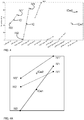
FIG. 4 illustrates an operational state of the embodiment of the apparatus ofFIGs. 1 and3 , -
FIG. 4A illustrates an operational state of an alternative embodiment of the apparatus ofFIGs. 1 and3 , -
FIG. 5 shows statistic data obtained from groups of subjects having various mental impairments, -
FIG. 6 illustrates another operational state of the embodiment of the apparatus ofFIGs. 1 and3 , -
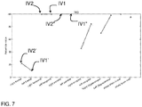
FIG. 7 illustrates again another operational state of the embodiment of the apparatus ofFIGs. 1 and3 , -
FIG. 8 illustrates an operational state of another embodiment of the apparatus ofFIGs. 1 and3 , -
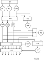
FIG. 9 illustrates in more detail an exemplary method of preparing reference data, -
FIG. 10 illustrates in more detail a method of preparing data for use in diagnosis of an individual. -
FIG. 1 schematically shows anapparatus 10 for assisting in providing a diagnosis of a brain characteristic of a mammal brain. Theapparatus 10 includes aninput facility 12, aconversion facility output device 16. The apparatus is configured and arranged such that in an operational mode of the apparatus theinput facility 12 receives a pair of values VL,VR and a pair of reference values VRL, VRR. The pair of values includes a first value VL indicative of a brain characteristic of a portion of a first part of the brain, here the left hemisphere (also denoted as left part) for a point in time and a second value VR indicative of a brain characteristic of a corresponding portion of a second part of the brain, here the right hemisphere (also denoted as right part) for that point in time. - In this connection it is noted that a portion of the left part of the brain may comprise one of the left frontal lobe, left parietal lobe, left occipital lobe, left temporal lobe, left limbic lobe, and left hippocampus. Still further more specific neuroanatomical regions can be identified in the brain. For example the cortex can be sub-divided into 49 "parcellation units" (PUs), which are mutually bounded by a sulcus, i.e. a depression or fissure between the folds of cortical grey matter (gyri). A corresponding portion of the right part of the brain is that part which is symmetrically arranged with respect to the portion of the left part of the brain that is considered. E.g. the corresponding portion of the left frontal lobe is the right frontal lobe.
- A brain characteristic may be any feature which can describe (phenotype) the brain. Examples are
- brain morphology [1,2,5,6,7]. This may include characteristics for volume and shape description of brain tissues, brain lobes and individual neurostructures (e.g. hippocampus)
- brain function [11]. This includes for example resting state fMRI measurements, functional MR measurements, and brain perfusion, e.g. as determined by arterial spin labeling (ASL)),
- brain connectivity [8,9,10]. Characteristics indicative for brain connectivity are for example diffusion measures such as fractional anisotropy and mean diffusivity, per region or tract, and
- brain pathology [3,4]. Examples are white matter integrity, e.g. in terms of white matter lesions, microbleeds, enlarged Virchow and Robin spaces etc. in certain regions.
- Literature further discussing these characteristics and corresponding measurement methods is specified by the bracketed number in the list of references attached herewith..
- The pair of reference values includes first and second reference data. The first reference data VRL indicates a cumulative distribution of the first value for the portion, e.g. for the left frontal lobe, in a reference population. The second reference data VRR indicates a cumulative distribution of the second value for the corresponding portion, e.g. the right frontal lobe, in the reference population. The
conversion facility conversion facility output device 16 generates a human accessible output signal SH which is indicative for a substantially monotonically increasing function of a difference between the third and the fourth value VPL, VPR. - In the embodiment shown, the
apparatus 10 is part of asystem 50, which further comprises one or more of: - a
scanning device - a
storage facility - Although some elements of the system are shown as separate parts they may implemented in practice as a single part. For example the
conversion facility scanning device storage facility -
FIG. 2 schematically shows a method for assisting in providing a diagnosis of a medical condition of a mammal brain, the brain having a left and a right part. - In a first step S1 of the method of
FIG. 2 , at least one pair of values VL,VR as well as at least one pair of reference values VRL,VRR is received.
The at least one pair of values includes a first value VL indicative of a brain characteristic of a portion of the left part of the brain for a point in time and a second value VR indicative of a brain characteristic of a corresponding portion of the right part of the brain for that point in time. - The at least one pair of reference values includes first reference data VRL indicative for a cumulative distribution of the value for said portion in a reference population and second reference VRR data indicative for a cumulative distribution of the second value for the corresponding portion in the reference population.
- The method may include a step S01 of establishing the at least one pair of values VL, VR, for example using a scanning device, such as an MRI device or a CT-scanner for obtaining three dimensional image data and using image analysis tools to derive the pair of values from the obtained three dimensional image data. The three dimensional image data may be represented as pixels in a series of two-dimensional images, or as voxels in a single three dimensional image. The three dimensional image data may be stored, for example in a compressed format. Alternatively the image data may be deleted after the at least one pair of values VL, VR is derived from the image data.
- Alternatively, this data may be already available on a data carrier and be retrieved in step S1 for example using a wired or wireless data-connection. Typically the reference data VRL, VRR will already be obtained is step S02 in earlier investigations and be available on a data carrier, so that it can be retrieved therefrom using a wired or wireless data-connection. Certain embodiments can be contemplated wherein the reference data is locally obtained.
- For example the method could be performed by a scanning device capable to obtain three dimensional image data that is equipped with image analysis tools for generating the reference data from the three dimensional image data as input for step S02.
- As indicated above, the at least one pair of reference values includes reference data indicative for a cumulative distribution of the values in a reference population. The distribution of each value for the reference population may be indicated in various ways.
- According to a first approach the cumulative distribution of a value of a brain characteristic of portion of a reference population may be indicated by a set of percentile values. Therein each percentile value Px specifies that for a particular percentage of the reference population a value of said brain characteristic lower than said percentile value is determined. E.g. 50% of the reference population has a value for said brain characteristic lower than P50 and 10% of the reference population has a value for said brain characteristic lower than P10.
- Alternatively, it may be contemplated to specify the reference distribution in other terms. For example if it is known that brain characteristic of the reference population is always distributed according to a particular type of distribution, it is sufficient to know the values of the parameters of the distribution and the percentile values can subsequently be calculated using these parameter values. For example if the reference distribution is known to be a cumulative normal distribution it is sufficient to provide a mean and a standard deviation of that normal distribution. For some type of distributions, e.g. a Poisson distribution, a single parameter is sufficient for this purpose.
- In step S2 a third value VPL is determined, that indicates the cumulative probability of the first value VL according to the first reference data VRL. Also a fourth value VPR is determined, that indicates the cumulative probability of the second value VR according to said second reference data VRR. E.g. the third value VPL indicates the percentage of the reference population having a value for the brain characteristic of a portion of the brain less than the value VL. Likewise the fourth value VPR indicates the percentage of the reference population having a value for the brain characteristic of a portion of the brain less than the value VR. It will be understood that instead of percentage another, equivalent indicator can be used. E.g. instead of a percentage, a fraction can be indicated. Still alternatively, the third value or the fourth value may respectively indicate the percentage or the fraction of the reference population for which a value higher than the measured value VL or VR was found.
- It is noted that the third and the fourth value VPL, VPR do not need to exactly indicate the respective fractions or percentages. For example using a set of ten percentile values P10, P20, ...,P100, a percentage x may be selected from the corresponding
values 10, 20,..., 100 as the third or the fourth value. E.g. if the value VL is less than P30, but greater than P20, the correspondingvalue 30 is returned as the value VPL. - Using the data obtained in the second step S2, a third step S3 is performed, wherein a human accessible output signal SH is generated that is indicative for a substantially monotonically increasing function of a difference between the third and the fourth value.
- In the embodiment shown in
FIG. 1 , the apparatus comprises a programmable computer and a computeraccessible medium 30 is provided that comprises a computer program with instructions for causing the programmable computer to execute the steps as specified. Alternatively the steps as specified may be executed by dedicated hardware, in which case it is not necessary to provide instructions. In again another embodiment some components may be provided as dedicated hardware, while other components are programmable. -
FIG. 3 shows part of an embodiment of the apparatus. In the embodiment shown therein theoutput device 16 comprises adisplay unit 161 and acontrol unit 162 that generates control signals SC for the display unit. -
FIG. 4 illustrates an operational state of the embodiment of the apparatus ofFIGs. 1 and3 . Therein the control unit 162 (seefigure 3 ) causes the display unit 161 (seefigure 3 )to display an icon IC, for example a line, having a first vertex IV1 which is determined by the third value VPL and a second vertex IV2 which is determined by the fourth value VPR. - In the embodiment of
FIG. 4 , thecontrol unit 162 causes thedisplay unit 161 to display a plurality of icons IC, IC'. In addition to the icon IC, which is associated with the left and right temporal lobes, for example a further icon IC' is displayed, which is associated with the left and right frontal lobes. - As the third value VPL indicates the cumulative probability of the first value VL in accordance with the first reference data and the fourth value VPR indicates the cumulative probability of the second value VR according to the second reference data (VRR), the icon IC has a size that is indicative for a substantially monotonically increasing function of a difference between the third and the fourth value VPL, VPR. In other words, the
output device 16 therewith generates a human accessible output signal (SH) which is indicative for a substantially monotonically increasing function of a difference between the third and the fourth value VPL, VPR. This applies similarly to other icons displayed in this embodiment, e.g. the icon IC'. Therewith, the image rendered by theoutput device 16 provides, in a single overview, information on the extent of asymmetry for various brain characteristics in terms of their distribution known from the reference population. This can be used as objective, quantitative information to support the diagnosis of a wide range of neurological diseases as is set out in more detail below. The values VL, VR, VPL, VPR indicate a volume of a particular brain portion. In additionFIG. 4 shows two further icons ICw1 and ICw2. ICw1 indicates the cumulative probability of a value determined for the combined volume of the grey and white matter tissue, according to reference data indicating the distribution of that value for a reference population. ICw2 indicates the cumulative probability of a value determined for the whole brain white matter lesion volume, according to reference data indicating the distribution of that value for a reference population. - In the embodiment illustrated with
FIG. 4 the plurality of icons are IC, IC' are arranged in mutually distinct spatial regions. In this case the spatial regions are arranged next to each other in a horizontal direction. Accordingly, the icons can be identified by their position on the display. -
FIG. 4A illustrates an operational state of an alternative embodiment of the apparatus ofFIGs. 1 and3 . In this embodiment the icons share a common spatial region. This enables an even better comparison between the various portions of the brain. In the embodiment shown the individual icons IV1, IV2, IV1', IV2', IV1" , IV2" , ICw1, ICw2 can be identified by their labels. By way of examples the icons IV1, IV2, IV1', IV2'and IV1" , IV2" can also be recognized by their appearance, here as a solid line, a dashed line and a dotted line. Icons ICw1, ICw2 are shown as a dark dot and a light dot. Alternatively or additionally, the different icons may be displayed in mutually different colors. - It has been found that the human accessible output signal SH obtained in this way is strongly indicative for the presences of certain mental disorders. By way of example
FIG. 5 shows statistic data obtained from groups of subjects having Alzheimer disease (AD), mild cognitive impairment (MCI) and fronto-temporal dementia (FTD). The diagnosis of these subjects is based on expert consensus review of clinical, laboratory and nuclear imaging data in combination with visual inspection of brain MRI images. -
FIG. 9 schematically illustrates how reference data was obtained from a healthy reference group of 5000 participants who were non-demented at time of MRI, as was part of the study exclusion criteria De Leeuw et al., Neurol Neurosurg Psychiatry. 2001 Jan;70(1):9-14., Ikram et al., Eur J Epidemiol. 2011 Oct;26(10):811-24. Epub 2011Oct 16, and Hofman et al., Eur J Epidemiol. 1991 Jul;7(4):403-22. - MRI images were obtained from each of the 5000 reference subjects as shown in step S1 using a1.5 T MRI system (General Electric Healthcare, Milwaukee, Wisconsin). The imaging protocol included a T1-weighted 3-dimensional fast radiofrequency spoiled gradient recalled acquisition in steady state with an inversion recovery prepulse sequence (TR = 13.8 milliseconds, TE = 2.8 milliseconds, inversion time = 400 milliseconds, FOV = 25 x 17.5 cm2, matrix = 416 x 256 [interpolated to 512 x 512], flip angle = 20°, NEX = 1, bandwidth [BW] = 12.50 kHz, 96 slices with a thickness = 1.6 mm zero-padded in the frequency domain to 0.8 mm, interpolated voxel size = 0.5 x 0.5 x 0.8 = 0.2 mm3), a proton density (PD)-weighted sequence (TR = 12 300 milliseconds, TE = 17.3 milliseconds, FOV = 25 x 17.5 cm2, matrix = 416 x 256, NEX = 1, BW = 17.86 kHz, 90 slices with slice thickness = 1.6 mm), and a fluid-attenuated inversion recovery (FLAIR) sequence (TR = 8000 milliseconds, TE = 120 milliseconds, inversion time = 2000 milliseconds, FOV = 25 x 25 cm2, matrix = 320 x 224, NEX = 1, BW = 31.25 kHz, 64 slices with slice thickness = 2.5 mm). All slices were contiguous.
- The MRI brain images of type T1, PD, and FLAIR so obtained were uploaded to a Linux workstation. Segmentation of brain tissue into gray matter (GM), white matter (WM), white matter lesions (WML) and cerebrospinal fluid (CSF) was performed using an automated algorithm as described by Cocosco et al. Med Image Anal 7 (4), 513-527 and Vrooman et al. Neuroimage. 2007 Aug 1;37(1):71-81. Epub 2007 May 21, with an extension for WML segmentation developed by de Boer et al. Neuroimage. 2009 May 1;45(4):1151-61.
- In short, in step S2, the T1, PD and FLAIR MRI images were registered and segmented in GM, WM and CSF using an automatically trained K-nearest-neighbor (Knn) classifier. Automatic training was achieved by non-rigid registration of GM, WM and CSF probability atlases, providing subject-specific training samples for subsequent Knn-classification.
- After Knn classification, the GM segmentation result was used in step S3 to perform automated thresholding on the FLAIR images to segment WML. Segmentation results were multiplied by the voxel dimensions to obtain WM, GM, WML and CSF volumes in ml for the whole brain. Whole brain volume WB was calculated in step S4 by adding WM, GM and WML volumes. Intracranial volume IV was calculated in step S5 by adding WM, GM, WML and CSF volumes.
- Hippocampal volumes were determined using FreeSurfer, i.e. a brain imaging software package developed by the Athinoula A. Martinos Center for Biomedical Imaging at Massachusetts General Hospital for analyzing magnetic resonance imaging (MRI) scan data. Also other methods can be used to determine the reference data for the hippocampal volume reference data provided that the same method is used to determine hippocampal volume data of the individual to be compared with the reference data.
- A brain atlas MAP was prepared by outlining brain regions on brain MRI images of 12 healthy individuals using anatomical landmarks provided by Bokde et al, Brain Res Brain Res Protoc. 2005 Apr; 14(3): 135-45.. All resulting anatomical atlases were non-rigidly registered, to the brain MRI images of the subject under investigation with the Elastix toolkit, See Klein et al. IEEE Trans Med Imaging. 2010 Jan;29(1):196-205. The eventual subject-tailored anatomical atlas MAP was obtained by merging the 12 anatomical atlases, using majority voting for the definitive label of each voxel. The definitive anatomical atlas MAP was used in step S6 to mask the original segmentation results, from which volumes V1,...Vn, for each brain lobe were calculated. All resulting volumes were divided by intracranial IV volume in step S7, to obtain relative volumes v1,..,vn..
- In step S8, age- and sex specific percentile curves were generated p1,...,pn for each quantified parameter (whole brain volume, lobar brain volumes, hippocampal volumes and WML volume) from the data obtained in step and further using the bibliographical data BD of the reference subjects. Step S8 was performed with an algorithm based on the LMS method (Cole et al., 1992).
- In short, the LMS method estimates the box-cox power transformation (λ), mean (µ) and coefficient of variation (o) for the appropriate volume at each value of the covariate age. From these parameters, percentile lines can be estimated for the appropriate age range.
- In a similar manner the relative volume data v1, ..., vn is obtained from individuals to be diagnosed, as schematically indicated in
FIG. 10 . Therewith each step Sk corresponds to a step Sk-10 inFIG. 9 . I.e. steps S11 to S17 inFIG. 10 correspond to steps S1 to S7 ofFIG. 9 respectively. The relative volume data v1, ..., vn therewith obtained serves as the values VL, VR indicative of a brain characteristic of a brain portion of the individual for a point in time. - The percentile lines p1,...,pn so obtained in step S8 of
FIG. 9 serve as the reference data VRL, VRR indicative for a cumulative distribution of the values VL, VR in a reference population. - An overview of statistical data of 42 individuals having a diagnosis of a cognitive impairment is provided in the following table. Therein the size N of each of these groups mild cognitive impairment (MCI), Alzheimer disease (AD), fronto-temporal dementia (FTD) is indicated between brackets. The table further indicates for each of these groups mean and standard deviation (SD) of the age of the subjects, the ratio between the genders, the average duration of time expired since the diagnosis. The table further indicates the values assessed by a minimal mental state examination (MMSE). The indication includes the median value as well as the interquartile range (IQR).
Table 1: Overview of statistical data for 42 individuals having a cognitive impairment. MCI (N=6) AD (N=21) FTD (N=15) Total (N=42) Age 63.2 (8.5) 66.1 (8.5) 60.0 (6.5) 63.5 (8.1) Mean (SD) Gender 2:4 12:9 9:6 23:19 M;F Duration (yrs) 1.1 (1.8-3.6) 2.1 (1.1-3.3) 2.1 (1.5-3.0) 2.1 (1.3-3.2) mean (SD) MMSE 25.5 (23.0-26.8) 24.0 (22.0-25.0) 25.5 (22.5-29.0) 24.5 (22.3-27.0) median, IQR -
FIG. 5 shows for each of these groups of subjects how the brain characteristic value for a particular portion of the left brain hemisphere is distributed in comparison to the reference distribution for that value for the same particular portion of the left brain hemisphere obtained from the healthy reference group of 5000 participants. - Likewise this comparison is shown for the brain characteristic value for the corresponding particular portion of the right brain hemisphere. The particular portions considered in this case are the mutually corresponding left and right frontal lobe, left and right temporal lobe, left and right parietal lobe, left and right occipital lobe, and the left and right hippocampus. In addition the comparison is made for "whole brain tissue" (grey and white matter volume) and the whole brain white matter lesion volume. In
FIG. 5 , the lower and upper boundary of the boxes respectively indicates the percentiles 25 and 75. The whiskers indicate the percentiles corresponding to 1.5 times the interquartile range (IQR). - By way of example it can be seen that the data obtained for group AD for the right frontal lobe the median value corresponds to P10 of the reference distribution. Furthermore the range of values between P25 and P75 of the distribution obtained for this group corresponds to the range P05 to P47 of the reference group.
- Returning now to the example of
FIG. 4 , it will be appreciated that the human accessible output signal SH as being provided therein shows a remarkable asymmetry. In particular the vertex IV1 of the signal SH indicates that the third value VPL = 85, indicating the cumulative probability of the first value according to the first reference data is relatively high. Contrary thereto, the vertex IV2 of the signal SH indicates that the fourth value VPR = 0 for the cumulative probability of the second value according to the second reference data is relatively low for the temporal lobes. - The medical specialist would tend to consider the diagnosis frontal temporal dementia as a possible explanation for this particular signal SH. This possible diagnosis is further supported by the observation pertaining to the frontal lobes. For the left frontal lobe, the vertex IV1' of the signal SH indicates that the third value VPL = 70, i.e. the cumulative probability of the first value according to the first reference data is relatively high. Contrary thereto, for the right frontal lobe the vertex IV2' of the signal SH indicates that the fourth value VPR = 0 i.e. the cumulative probability of the second value according to the second reference data is relatively low.
- As another example,
FIG. 6 shows the human accessible output signal SH as generated by the present method for another person. In this case the vertices IV1, IV2 of the human accessible output signal SH for the temporal lobes show that the third value VPL and the fourth value VPR both are very low, i.e. about 5% and 10% respectively. I.e. a substantial atrophy as compared with the reference population is indicated for both temporal lobes.
The same is determined for each of the other parts of the brain. In particular human accessible output signal SH' indicates by vertices IV1', IV2', that also a substantial symmetric atrophy occurred, in the hippocampi. Also a symmetric atrophy in the parietal lobes would support this diagnosis, in particular for younger Alzheimer patients. By taking into account the age of the reference population in generating the first and second reference data a more reliable diagnosis can be given. On the one hand avoiding that normal atrophy occurring with elderly erroneously results in the diagnosis of Alzheimer. On the other hand it is avoided that a certain degree of atrophy which as such be normal for an older person would not be recognized as a indication of Alzheimer when diagnosing a younger person. - As a further example,
FIG. 8 shows the human accessible output signal SH as generated by the present method for again another person. It will be appreciated in the example shown that the human accessible output signal SH indicates that both the third value VPL and the fourth value VPR as determined for the temporal lobes is extremely high, i.e. about 100%. This provides an indication for an impairment other than Alzheimer or fronto-temporal dementia. The medical specialist may in that connection consider the diagnosis MCI as this is an further important class of mental disorders occurring with the elderly. To verify this, the medical specialist may observe further human accessible output signals, such as a signal indicating a substantially monotonically increasing function of a difference between the third and the fourth value for the frontal lobes. In that case the medical specialist observes that the third and the fourth values the frontal lobes are very low i.e. 10% and 25% as compared to the reference group. In view of the low value indicated for both sides the suspicion that the person suffers from Mild Cognitive Impairment is reinforced. -
FIG. 8 shows operation of a further embodiment. In particular, in the embodiment shown, the output device generates a first and a second human accessible output signal which each are indicative for a substantially monotonically increasing function of a difference between a third and a fourth value. In particular the output device generates the first and the second human accessible output signal for the frontal lobes and the temporal lobes respectively. - To that end the output device generates an image of a rectangle. Its horizontal side extends over a trajectory determined by the third value VPL and the fourth value VPR for the frontal lobes. More in particular the horizontal side extends from a first coordinate indicating the lowest one to a second coordinate indicating the highest one of this third value VPL and this fourth value VPR. The vertical side of the rectangle extends over a trajectory determined by the third value VPL and the fourth value VPR for the temporal lobes. More in particular the vertical side extends from a first coordinate indicating the lowest one to a second coordinate indicating the highest one of this third value VPL and this fourth value VPR.
- It will be understood that during normal operation, the
output device 16 only shows a human accessible output signals SH, SH' as determined for a particular person for which a diagnosis has to be made. For illustrative purposes,FIG. 8 shows the human accessible output signals SH, SH' that would be generated by the apparatus for each of the three cases presented with reference toFIG. 4 ,6 and7 respectively. From this combined view it is immediately clear that the rectangle that is rendered by theoutput device 16 based on the combination of human accessible output signals SH, SH' is strongly indicative for the type of mental disorder. - Particularly notifiable is the rectangle denoted as FTD, which is rendered on the basis of the same data as used for
FIG. 4 . In this case the first human accessible output signal SH indicates a substantial difference between the third and the fourth value for the frontal lobes. The second human accessible output signal SH' indicates a substantial difference between the third and the fourth value for the temporal lobes. Therewith the generally asymmetric nature of the atrophy occurring with fronto temporal dementia is clearly visualized by theoutput device 16 as a rectangle having a large area. - As a further example, the rectangle denoted as AD, is shown, which is rendered on the basis of the same data as used for
FIG. 6 . In this case the first human accessible output signal SH indicates that the third and the fourth value for the frontal lobes are both extremely low. The second human accessible output signal SH' indicates further that the third and the fourth value for the temporal lobes are extremely low. Therewith the generally symmetric nature of the atrophy occurring with Alzheimer disease in multiple parts of the brain is clearly visualized by theoutput device 16 as a small rectangle in the lower left part of the image. - As a still further example, the rectangle denoted as MCI, is shown, which is rendered on the basis of the same data as used for
FIG. 7 . In this case the first human accessible output signal SH indicates that the third and the fourth value for the frontal lobes are both extremely low. Contrary thereto, the second human accessible output signal SH' indicates that the third and the fourth value for the temporal lobes are extremely high. Therewith the generally symmetric nature of the atrophy occurring with mild cognitive impairment in selected parts of the brain is clearly visualized by theoutput device 16 as a small rectangle in the upper left part of the image. -
- [1] de Boer R, Vrooman HA, Ikram MA, Vernooij MW, Breteler MMB, van der Lugt A, Niessen WJ. Accuracy and reproducibility study of automatic MRI brain tissue segmentation methods. NeuroImage. 2010;51(3):1047-56.
- [2] Vrooman HA, Cocosco CA, van der Lijn F, Stokking R, Ikram MA, Vernooij MW, Breteler MMB, Niessen WJ. Multi-spectral brain tissue segmentation using automatically trained k-Nearest-Neighbor classification. NeuroImage. 2007;37(1):71-81.
- [3] de Boer R, Vrooman HA, van der Lijn F, Vernooij MW, Ikram MA, van der Lugt A, Breteler MMB, Niessen WJ. White matter lesion extension to automatic brain tissue segmentation on MRI. NeuroImage. 2009;45(4):1151-61.
- [4] Van der Lijn F, Verhaaren BFJ, Ikram MA, Klein S, De Bruijne M, Vrooman HA, Vernooij MW, Hammers A, Rueckert D, Van der Lugt A, Breteler MMB, Niessen WJ. Automated measurement of local white matter lesion volume. NeuroImage. 2012;59(4):3901-8.
- [5] Van Der Lijn F, De Bruijne M, Klein S, Den Heijer T, Hoogendam YY, Van Der Lugt A, Breteler MMB, Niessen WJ. Automated brain structure segmentation based on atlas registration and appearance models. IEEE Transactions on Medical Imaging. 2012;31(2):276-86.
- [6] van der Lijn F, den Heijer T, Breteler MMB, Niessen WJ. Hippocampus segmentation in MR images using atlas registration, voxel classification, and graph cuts. NeuroImage. 2008;43(4):708-20.
- [7] Achterberg HC, van der Lijn F, den Heijer T, Vernooij MW, Ikram MA, Niessen WJ, de Bruijne M. Hippocampal shape is predictive for the development of dementia in a normal, elderly population. Human Brain Mapping. 2014;35(5):2359-71.
- [8] de Groot M, Ikram MA, Akoudad S, Krestin GP, Hofman A, van der Lugt A, et al. Tract-specific white matter degeneration in aging. The Rotterdam Study. Alzheimer's and Dementia. 2014.
- [9] De Groot M, Vernooij MW, Klein S, Ikram MA, Vos FM, Smith SM, Niessen WJ, Andersson JLR. Improving alignment in Tract-based spatial statistics: Evaluation and optimization of image registration. NeuroImage. 2013;76:400-11.
- [10] de Boer R, Schaap M, van der Lijn F, Vrooman HA, de Groot M, van der Lugt A, Ikram MA, Vernooij MW, Breteler MMB, Niessen WJ. Statistical analysis of minimum cost path based structural brain connectivity. NeuroImage. 2011;55(2):557-65.
- [11] Bron EE, Steketee RM, Houston GC, Oliver RA, Achterberg HC, Loog M, van Swieten JC, Hammers A, Niessen WJ, Smits M, Klein S. Diagnostic classification of arterial spin labeling and structural MRI in presenile early stage dementia. Human Brain Mapping. 2014.
Claims (14)
- An apparatus for assisting in providing a diagnosis of a medical condition of a mammal brain, the brain having a first and a second part, the apparatus including an input facility, a conversion facility, and an output device comprising a display unit for generating an output signal, the apparatus being configured and arranged such that in an operational mode of the apparatus the input facility receives from a scanning device with image analysis functionality at least one pair of values determined by the image analysis functionality, and receives from a storage facility at least one pair of reference values, the at least one pair of values including:-- a first value indicative of a brain characteristic of a portion of the first part of the brain for a point in time;-- a second value indicative of a brain characteristic of a corresponding portion of the second part of the brain for said point in time;the at least one pair of reference values including:-- first reference data indicative for a cumulative distribution of said first value for said portion in a reference population; and-- second reference data indicative for a cumulative distribution of said second value for said corresponding portion in said reference population;wherein the conversion facility determines a third value, indicating the cumulative probability of said first value according to said first reference data and a fourth value, indicating the cumulative probability of said second value according to said second reference data, and wherein the display unit generates as the output signal a output signal that is indicative for a monotonically increasing function of a difference between the third and the fourth value.
- The apparatus according to claim 1, wherein the first part is the left hemisphere of the brain and the second part is the right hemisphere of the brain.
- The apparatus according to claim 1 or 2, wherein the output device comprises a control unit for said display unit.
- The apparatus according to claim 3, wherein in an operational state of the apparatus said control unit causes said display unit to display an icon having a first vertex which is determined by the third value and a second vertex which is determined by the fourth value.
- The apparatus according to claim 4, wherein in an operational state of the apparatus said control unit causes said display unit to display a plurality of icons having a respective pair of a first vertex and a second vertex, each respective pair of vertices of each icon being associated with a respective portion of the first part of the brain and its corresponding portion of the second part of the brain, the first vertex being determined by the third value for said portion and the second vertex being determined by the fourth value for said portion.
- The apparatus according to claim 4, wherein in an operational state of the apparatus said control unit causes said display unit to display a rectangle, with first sides and second sides transverse to said first sides, which first sides extend over a trajectory determined by the third value determined by a first portion of the first part of the brain and the fourth value determined for the portion corresponding to said first portion in the second part of the brain, which second sides extend over a trajectory determined by the third value determined by a second portion of the first part of the brain and the fourth value determined for the portion corresponding to said second portion in the second part of the brain,
- The apparatus according to claim 6, wherein the horizontal side extends from a first coordinate to a second coordinate, the first and the second coordinate respectively indicating the lowest one and the highest one of the third value VPL for said first portion and the fourth value VPR for said portion corresponding to the first portion, and wherein the vertical side extends from a third coordinate to a fourth coordinate, the third and the fourth coordinate respectively indicating the lowest one and the highest one of the third value VPL for said second portion and the fourth value VPR for said portion corresponding to the second portion.
- The apparatus according to claim 3, wherein in an operational state of the apparatus said control unit causes said display unit to display a virtual image of the human brain and indicating therein said portion with a color and/or brightness as determined by said third value and said corresponding portion with a color and/or brightness as determined by said fourth value.
- The apparatus according to one of the previous claims, wherein in an operational state of the apparatus the at least one pair of values is obtained from at least a first and a second pair of a first value and second value, the first and the second pair of values being obtained at mutually different points in time, wherein the conversion facility determines for each of said mutually different points in time a pair of a third value and a fourth value associated with the first and the second pair of values obtained for said mutually different points in time, and wherein the output device generates a first human accessible output signal which is indicative for a monotonically increasing function of a difference between the third and the fourth value of said at least a first pair of the third and the fourth value and a second human accessible output signal which is indicative for a monotonically increasing function of a difference between the third and the fourth value of said at least a second pair of the third and the fourth value.
- The apparatus according to claim 9, wherein the output device simultaneously generates the first human accessible output signal and the second human accessible output signal.
- The apparatus according to claim 9, wherein the output device sequentially generates the first human accessible output signal and the second human accessible output signal in an order corresponding to the order in time in which the first and the second pair of a first value and second value were obtained and separated by a time interval that is smaller than the time interval between said mutually different points in time.
- A system comprising an apparatus according to one of the claims 1 to 11, and further comprising one or more of:- a scanning device equipped with image analysis tools for determining the first value and the second value; and- a storage facility for storing and providing said first and said second reference data.
- A method for assisting in providing a diagnosis of a medical condition of a mammal brain, the brain having a first and a right part, the method including - receiving from a scanning device with image analysis functionality at least one pair of values determined by the image analysis functionality, and receiving from a storage facility at least one pair of reference values, the at least one pair of values including:-- a first value indicative of a brain characteristic of a portion of the first part of the brain for a point in time;-- a second value indicative of a brain characteristic of a corresponding portion of the right part of the brain for said point in time;the at least one pair of reference values including:-- first reference data indicative for a cumulative distribution of said first value for said portion in a reference population; and-- second reference data indicative for a cumulative distribution of said second value for said corresponding portion in said reference population;- determining a third value, indicating the cumulative probability of said first value according to said first reference data and a fourth value, , indicating the cumulative probability of said second value according to said second reference data, and- displaying an output signal which is indicative for a monotonically increasing function of a difference between the third and the fourth value.
- A computer accessible medium comprising a computer program with instructions for causing a programmable computer to execute each of the steps of the method of claim 13.
Applications Claiming Priority (2)
| Application Number | Priority Date | Filing Date | Title |
|---|---|---|---|
| PCT/NL2015/050505 WO2017010864A1 (en) | 2015-07-10 | 2015-07-10 | Apparatus, system and method for assisting in providing a diagnosis of a medical condition of a mammal brain as well a computer readable medium comprising a program for carrying out the method |
| PCT/NL2016/050499 WO2017010873A1 (en) | 2015-07-10 | 2016-07-08 | Apparatus, system and method for assisting in providing a diagnosis of a medical condition of a mammal brain as well a computer readable medium comprising a program for carrying out the method |
Publications (2)
| Publication Number | Publication Date |
|---|---|
| EP3320520A1 EP3320520A1 (en) | 2018-05-16 |
| EP3320520B1 true EP3320520B1 (en) | 2019-09-04 |
Family
ID=53801137
Family Applications (1)
| Application Number | Title | Priority Date | Filing Date |
|---|---|---|---|
| EP16751029.6A Active EP3320520B1 (en) | 2015-07-10 | 2016-07-08 | Apparatus, system and method for assisting in providing a diagnosis of a medical condition of a mammal brain as well a computer readable medium comprising a program for carrying out the method |
Country Status (4)
| Country | Link |
|---|---|
| US (1) | US10772573B2 (en) |
| EP (1) | EP3320520B1 (en) |
| ES (1) | ES2759803T3 (en) |
| WO (2) | WO2017010864A1 (en) |
Families Citing this family (3)
| Publication number | Priority date | Publication date | Assignee | Title |
|---|---|---|---|---|
| EP4040445A4 (en) * | 2019-09-30 | 2023-10-25 | Rainbow Inc. | Method, program, and device for evaluating state of motor function |
| AU2021440013A1 (en) * | 2021-04-09 | 2023-10-26 | Wellumio Limited | Perfusion measurement with low field nmr |
| WO2023048557A1 (en) * | 2021-09-27 | 2023-03-30 | Genting Taurx Diagnostic Centre Sdn Bhd | Determining an indication as to whether a patient has a neurocognitive disease |
Family Cites Families (2)
| Publication number | Priority date | Publication date | Assignee | Title |
|---|---|---|---|---|
| EP2629264A1 (en) | 2006-12-06 | 2013-08-21 | Agency for Science, Technology And Research | Identifying in which brain hemisphere a pathological region is located |
| WO2011142725A1 (en) * | 2010-05-14 | 2011-11-17 | Agency For Science, Technology And Research | Method and device for processing a computed tomography measurement result |
-
2015
- 2015-07-10 WO PCT/NL2015/050505 patent/WO2017010864A1/en not_active Ceased
-
2016
- 2016-07-08 US US15/743,209 patent/US10772573B2/en not_active Expired - Fee Related
- 2016-07-08 ES ES16751029T patent/ES2759803T3/en active Active
- 2016-07-08 EP EP16751029.6A patent/EP3320520B1/en active Active
- 2016-07-08 WO PCT/NL2016/050499 patent/WO2017010873A1/en not_active Ceased
Non-Patent Citations (1)
| Title |
|---|
| None * |
Also Published As
| Publication number | Publication date |
|---|---|
| EP3320520A1 (en) | 2018-05-16 |
| WO2017010864A1 (en) | 2017-01-19 |
| US10772573B2 (en) | 2020-09-15 |
| US20180206800A1 (en) | 2018-07-26 |
| ES2759803T3 (en) | 2020-05-12 |
| WO2017010873A1 (en) | 2017-01-19 |
Similar Documents
| Publication | Publication Date | Title |
|---|---|---|
| JP5699936B2 (en) | Method, apparatus and program for operating medical image processing apparatus | |
| den Heijer et al. | Structural and diffusion MRI measures of the hippocampus and memory performance | |
| Colliot et al. | Individual voxel-based analysis of gray matter in focal cortical dysplasia | |
| US8280482B2 (en) | Method and apparatus for evaluating regional changes in three-dimensional tomographic images | |
| US20030009098A1 (en) | Histogram segmentation of FLAIR images | |
| US20110046451A1 (en) | Method and automated system for assisting in the prognosis of alzheimer's disease, and method for training such a system | |
| CN109997200A (en) | Stroke diagnosis and method for prediction of prognosis and system | |
| EP2747658B1 (en) | Method to compute and present brain amyloid in gray matter | |
| WO2011163391A2 (en) | Atlas-based analysis for image-based anatomic and functional data of organism | |
| US20140226882A1 (en) | Simultaneous segmentation and grading of structures for state determination | |
| Sederevičius et al. | Reliability and sensitivity of two whole-brain segmentation approaches included in FreeSurfer–ASEG and SAMSEG | |
| US11403755B2 (en) | Medical information display apparatus, medical information display method, and medical information display program | |
| US20150356733A1 (en) | Medical image processing | |
| JP2014042684A (en) | Medical image processing device, and program | |
| US11219402B2 (en) | Systems and methods for producing imaging biomarkers indicative of a neurological disease state using gray matter suppressions via double inversion-recovery magnetic resonance imaging | |
| US10772573B2 (en) | Apparatus, system and method for assisting in providing a diagnosis of a medical condition of a mammal brain as well a computer readable medium comprising a program for carrying out the method | |
| Goodkin et al. | FLAIR-only joint volumetric analysis of brain lesions and atrophy in clinically isolated syndrome (CIS) suggestive of multiple sclerosis | |
| Griffanti et al. | Adapting UK Biobank imaging for use in a routine memory clinic setting: The Oxford Brain Health Clinic | |
| Wang et al. | Semi-automatic segmentation of the fetal brain from magnetic resonance imaging | |
| EP3983994B1 (en) | A method for measuring tracer uptake in cerebral tissue by analyzing images acquired by positron emission tomography (pet) | |
| Okawa et al. | Comparison of qualitative and fully automated quantitative tools for classifying severity of white matter hyperintensity | |
| CN117974584A (en) | Brain image analysis method, system and computer storage medium | |
| KR20210024853A (en) | Diagnosis Method and System of Idiopathic Normal Pressure Hydrocephalus Using Imaging Diagnostic Equipment | |
| KR20160007406A (en) | Method and apparatus for displaying pathological changes in an examination object based on 3d data records | |
| Kitzberger et al. | Automatic Disentanglement of Motion in Fetal Low Field MRI Scans |
Legal Events
| Date | Code | Title | Description |
|---|---|---|---|
| STAA | Information on the status of an ep patent application or granted ep patent |
Free format text: STATUS: THE INTERNATIONAL PUBLICATION HAS BEEN MADE |
|
| PUAI | Public reference made under article 153(3) epc to a published international application that has entered the european phase |
Free format text: ORIGINAL CODE: 0009012 |
|
| STAA | Information on the status of an ep patent application or granted ep patent |
Free format text: STATUS: REQUEST FOR EXAMINATION WAS MADE |
|
| 17P | Request for examination filed |
Effective date: 20180202 |
|
| AK | Designated contracting states |
Kind code of ref document: A1 Designated state(s): AL AT BE BG CH CY CZ DE DK EE ES FI FR GB GR HR HU IE IS IT LI LT LU LV MC MK MT NL NO PL PT RO RS SE SI SK SM TR |
|
| AX | Request for extension of the european patent |
Extension state: BA ME |
|
| DAV | Request for validation of the european patent (deleted) | ||
| DAX | Request for extension of the european patent (deleted) | ||
| GRAP | Despatch of communication of intention to grant a patent |
Free format text: ORIGINAL CODE: EPIDOSNIGR1 |
|
| STAA | Information on the status of an ep patent application or granted ep patent |
Free format text: STATUS: GRANT OF PATENT IS INTENDED |
|
| INTG | Intention to grant announced |
Effective date: 20190322 |
|
| INTG | Intention to grant announced |
Effective date: 20190322 |
|
| GRAS | Grant fee paid |
Free format text: ORIGINAL CODE: EPIDOSNIGR3 |
|
| GRAA | (expected) grant |
Free format text: ORIGINAL CODE: 0009210 |
|
| STAA | Information on the status of an ep patent application or granted ep patent |
Free format text: STATUS: THE PATENT HAS BEEN GRANTED |
|
| AK | Designated contracting states |
Kind code of ref document: B1 Designated state(s): AL AT BE BG CH CY CZ DE DK EE ES FI FR GB GR HR HU IE IS IT LI LT LU LV MC MK MT NL NO PL PT RO RS SE SI SK SM TR |
|
| REG | Reference to a national code |
Ref country code: GB Ref legal event code: FG4D |
|
| REG | Reference to a national code |
Ref country code: CH Ref legal event code: EP |
|
| REG | Reference to a national code |
Ref country code: AT Ref legal event code: REF Ref document number: 1176446 Country of ref document: AT Kind code of ref document: T Effective date: 20190915 |
|
| REG | Reference to a national code |
Ref country code: DE Ref legal event code: R096 Ref document number: 602016020007 Country of ref document: DE |
|
| REG | Reference to a national code |
Ref country code: IE Ref legal event code: FG4D |
|
| REG | Reference to a national code |
Ref country code: NL Ref legal event code: FP |
|
| REG | Reference to a national code |
Ref country code: LT Ref legal event code: MG4D |
|
| PG25 | Lapsed in a contracting state [announced via postgrant information from national office to epo] |
Ref country code: SE Free format text: LAPSE BECAUSE OF FAILURE TO SUBMIT A TRANSLATION OF THE DESCRIPTION OR TO PAY THE FEE WITHIN THE PRESCRIBED TIME-LIMIT Effective date: 20190904 Ref country code: BG Free format text: LAPSE BECAUSE OF FAILURE TO SUBMIT A TRANSLATION OF THE DESCRIPTION OR TO PAY THE FEE WITHIN THE PRESCRIBED TIME-LIMIT Effective date: 20191204 Ref country code: NO Free format text: LAPSE BECAUSE OF FAILURE TO SUBMIT A TRANSLATION OF THE DESCRIPTION OR TO PAY THE FEE WITHIN THE PRESCRIBED TIME-LIMIT Effective date: 20191204 Ref country code: HR Free format text: LAPSE BECAUSE OF FAILURE TO SUBMIT A TRANSLATION OF THE DESCRIPTION OR TO PAY THE FEE WITHIN THE PRESCRIBED TIME-LIMIT Effective date: 20190904 Ref country code: FI Free format text: LAPSE BECAUSE OF FAILURE TO SUBMIT A TRANSLATION OF THE DESCRIPTION OR TO PAY THE FEE WITHIN THE PRESCRIBED TIME-LIMIT Effective date: 20190904 Ref country code: LT Free format text: LAPSE BECAUSE OF FAILURE TO SUBMIT A TRANSLATION OF THE DESCRIPTION OR TO PAY THE FEE WITHIN THE PRESCRIBED TIME-LIMIT Effective date: 20190904 |
|
| PG25 | Lapsed in a contracting state [announced via postgrant information from national office to epo] |
Ref country code: LV Free format text: LAPSE BECAUSE OF FAILURE TO SUBMIT A TRANSLATION OF THE DESCRIPTION OR TO PAY THE FEE WITHIN THE PRESCRIBED TIME-LIMIT Effective date: 20190904 Ref country code: RS Free format text: LAPSE BECAUSE OF FAILURE TO SUBMIT A TRANSLATION OF THE DESCRIPTION OR TO PAY THE FEE WITHIN THE PRESCRIBED TIME-LIMIT Effective date: 20190904 Ref country code: GR Free format text: LAPSE BECAUSE OF FAILURE TO SUBMIT A TRANSLATION OF THE DESCRIPTION OR TO PAY THE FEE WITHIN THE PRESCRIBED TIME-LIMIT Effective date: 20191205 Ref country code: AL Free format text: LAPSE BECAUSE OF FAILURE TO SUBMIT A TRANSLATION OF THE DESCRIPTION OR TO PAY THE FEE WITHIN THE PRESCRIBED TIME-LIMIT Effective date: 20190904 |
|
| REG | Reference to a national code |
Ref country code: AT Ref legal event code: MK05 Ref document number: 1176446 Country of ref document: AT Kind code of ref document: T Effective date: 20190904 |
|
| PG25 | Lapsed in a contracting state [announced via postgrant information from national office to epo] |
Ref country code: PL Free format text: LAPSE BECAUSE OF FAILURE TO SUBMIT A TRANSLATION OF THE DESCRIPTION OR TO PAY THE FEE WITHIN THE PRESCRIBED TIME-LIMIT Effective date: 20190904 Ref country code: PT Free format text: LAPSE BECAUSE OF FAILURE TO SUBMIT A TRANSLATION OF THE DESCRIPTION OR TO PAY THE FEE WITHIN THE PRESCRIBED TIME-LIMIT Effective date: 20200106 Ref country code: RO Free format text: LAPSE BECAUSE OF FAILURE TO SUBMIT A TRANSLATION OF THE DESCRIPTION OR TO PAY THE FEE WITHIN THE PRESCRIBED TIME-LIMIT Effective date: 20190904 Ref country code: EE Free format text: LAPSE BECAUSE OF FAILURE TO SUBMIT A TRANSLATION OF THE DESCRIPTION OR TO PAY THE FEE WITHIN THE PRESCRIBED TIME-LIMIT Effective date: 20190904 Ref country code: AT Free format text: LAPSE BECAUSE OF FAILURE TO SUBMIT A TRANSLATION OF THE DESCRIPTION OR TO PAY THE FEE WITHIN THE PRESCRIBED TIME-LIMIT Effective date: 20190904 |
|
| REG | Reference to a national code |
Ref country code: ES Ref legal event code: FG2A Ref document number: 2759803 Country of ref document: ES Kind code of ref document: T3 Effective date: 20200512 |
|
| PG25 | Lapsed in a contracting state [announced via postgrant information from national office to epo] |
Ref country code: IS Free format text: LAPSE BECAUSE OF FAILURE TO SUBMIT A TRANSLATION OF THE DESCRIPTION OR TO PAY THE FEE WITHIN THE PRESCRIBED TIME-LIMIT Effective date: 20200224 Ref country code: SM Free format text: LAPSE BECAUSE OF FAILURE TO SUBMIT A TRANSLATION OF THE DESCRIPTION OR TO PAY THE FEE WITHIN THE PRESCRIBED TIME-LIMIT Effective date: 20190904 Ref country code: CZ Free format text: LAPSE BECAUSE OF FAILURE TO SUBMIT A TRANSLATION OF THE DESCRIPTION OR TO PAY THE FEE WITHIN THE PRESCRIBED TIME-LIMIT Effective date: 20190904 Ref country code: SK Free format text: LAPSE BECAUSE OF FAILURE TO SUBMIT A TRANSLATION OF THE DESCRIPTION OR TO PAY THE FEE WITHIN THE PRESCRIBED TIME-LIMIT Effective date: 20190904 |
|
| REG | Reference to a national code |
Ref country code: DE Ref legal event code: R097 Ref document number: 602016020007 Country of ref document: DE |
|
| PLBE | No opposition filed within time limit |
Free format text: ORIGINAL CODE: 0009261 |
|
| STAA | Information on the status of an ep patent application or granted ep patent |
Free format text: STATUS: NO OPPOSITION FILED WITHIN TIME LIMIT |
|
| PG2D | Information on lapse in contracting state deleted |
Ref country code: IS |
|
| PG25 | Lapsed in a contracting state [announced via postgrant information from national office to epo] |
Ref country code: DK Free format text: LAPSE BECAUSE OF FAILURE TO SUBMIT A TRANSLATION OF THE DESCRIPTION OR TO PAY THE FEE WITHIN THE PRESCRIBED TIME-LIMIT Effective date: 20190904 Ref country code: IS Free format text: LAPSE BECAUSE OF FAILURE TO SUBMIT A TRANSLATION OF THE DESCRIPTION OR TO PAY THE FEE WITHIN THE PRESCRIBED TIME-LIMIT Effective date: 20200105 |
|
| 26N | No opposition filed |
Effective date: 20200605 |
|
| PG25 | Lapsed in a contracting state [announced via postgrant information from national office to epo] |
Ref country code: SI Free format text: LAPSE BECAUSE OF FAILURE TO SUBMIT A TRANSLATION OF THE DESCRIPTION OR TO PAY THE FEE WITHIN THE PRESCRIBED TIME-LIMIT Effective date: 20190904 |
|
| REG | Reference to a national code |
Ref country code: DE Ref legal event code: R119 Ref document number: 602016020007 Country of ref document: DE |
|
| PG25 | Lapsed in a contracting state [announced via postgrant information from national office to epo] |
Ref country code: MC Free format text: LAPSE BECAUSE OF FAILURE TO SUBMIT A TRANSLATION OF THE DESCRIPTION OR TO PAY THE FEE WITHIN THE PRESCRIBED TIME-LIMIT Effective date: 20190904 |
|
| REG | Reference to a national code |
Ref country code: CH Ref legal event code: PL |
|
| REG | Reference to a national code |
Ref country code: NL Ref legal event code: MM Effective date: 20200801 |
|
| GBPC | Gb: european patent ceased through non-payment of renewal fee |
Effective date: 20200708 |
|
| REG | Reference to a national code |
Ref country code: BE Ref legal event code: MM Effective date: 20200731 |
|
| PG25 | Lapsed in a contracting state [announced via postgrant information from national office to epo] |
Ref country code: LU Free format text: LAPSE BECAUSE OF NON-PAYMENT OF DUE FEES Effective date: 20200708 Ref country code: LI Free format text: LAPSE BECAUSE OF NON-PAYMENT OF DUE FEES Effective date: 20200731 Ref country code: CH Free format text: LAPSE BECAUSE OF NON-PAYMENT OF DUE FEES Effective date: 20200731 Ref country code: FR Free format text: LAPSE BECAUSE OF NON-PAYMENT OF DUE FEES Effective date: 20200731 Ref country code: GB Free format text: LAPSE BECAUSE OF NON-PAYMENT OF DUE FEES Effective date: 20200708 |
|
| PG25 | Lapsed in a contracting state [announced via postgrant information from national office to epo] |
Ref country code: DE Free format text: LAPSE BECAUSE OF NON-PAYMENT OF DUE FEES Effective date: 20210202 Ref country code: BE Free format text: LAPSE BECAUSE OF NON-PAYMENT OF DUE FEES Effective date: 20200731 |
|
| PG25 | Lapsed in a contracting state [announced via postgrant information from national office to epo] |
Ref country code: NL Free format text: LAPSE BECAUSE OF NON-PAYMENT OF DUE FEES Effective date: 20200801 |
|
| PG25 | Lapsed in a contracting state [announced via postgrant information from national office to epo] |
Ref country code: IE Free format text: LAPSE BECAUSE OF NON-PAYMENT OF DUE FEES Effective date: 20200708 |
|
| PG25 | Lapsed in a contracting state [announced via postgrant information from national office to epo] |
Ref country code: IT Free format text: LAPSE BECAUSE OF NON-PAYMENT OF DUE FEES Effective date: 20200708 |
|
| REG | Reference to a national code |
Ref country code: ES Ref legal event code: FD2A Effective date: 20211129 |
|
| PG25 | Lapsed in a contracting state [announced via postgrant information from national office to epo] |
Ref country code: ES Free format text: LAPSE BECAUSE OF NON-PAYMENT OF DUE FEES Effective date: 20200709 |
|
| PG25 | Lapsed in a contracting state [announced via postgrant information from national office to epo] |
Ref country code: TR Free format text: LAPSE BECAUSE OF FAILURE TO SUBMIT A TRANSLATION OF THE DESCRIPTION OR TO PAY THE FEE WITHIN THE PRESCRIBED TIME-LIMIT Effective date: 20190904 Ref country code: MT Free format text: LAPSE BECAUSE OF FAILURE TO SUBMIT A TRANSLATION OF THE DESCRIPTION OR TO PAY THE FEE WITHIN THE PRESCRIBED TIME-LIMIT Effective date: 20190904 Ref country code: CY Free format text: LAPSE BECAUSE OF FAILURE TO SUBMIT A TRANSLATION OF THE DESCRIPTION OR TO PAY THE FEE WITHIN THE PRESCRIBED TIME-LIMIT Effective date: 20190904 |
|
| PG25 | Lapsed in a contracting state [announced via postgrant information from national office to epo] |
Ref country code: MK Free format text: LAPSE BECAUSE OF FAILURE TO SUBMIT A TRANSLATION OF THE DESCRIPTION OR TO PAY THE FEE WITHIN THE PRESCRIBED TIME-LIMIT Effective date: 20190904 |