EP3319789B1 - Method for producing a fiber laminate component of an airplane - Google Patents
Method for producing a fiber laminate component of an airplane Download PDFInfo
- Publication number
- EP3319789B1 EP3319789B1 EP16736114.6A EP16736114A EP3319789B1 EP 3319789 B1 EP3319789 B1 EP 3319789B1 EP 16736114 A EP16736114 A EP 16736114A EP 3319789 B1 EP3319789 B1 EP 3319789B1
- Authority
- EP
- European Patent Office
- Prior art keywords
- layer
- fiber
- end effector
- gripping
- deposition surface
- Prior art date
- Legal status (The legal status is an assumption and is not a legal conclusion. Google has not performed a legal analysis and makes no representation as to the accuracy of the status listed.)
- Active
Links
Images
Classifications
-
- B—PERFORMING OPERATIONS; TRANSPORTING
- B29—WORKING OF PLASTICS; WORKING OF SUBSTANCES IN A PLASTIC STATE IN GENERAL
- B29C—SHAPING OR JOINING OF PLASTICS; SHAPING OF MATERIAL IN A PLASTIC STATE, NOT OTHERWISE PROVIDED FOR; AFTER-TREATMENT OF THE SHAPED PRODUCTS, e.g. REPAIRING
- B29C70/00—Shaping composites, i.e. plastics material comprising reinforcements, fillers or preformed parts, e.g. inserts
- B29C70/02—Shaping composites, i.e. plastics material comprising reinforcements, fillers or preformed parts, e.g. inserts comprising combinations of reinforcements, e.g. non-specified reinforcements, fibrous reinforcing inserts and fillers, e.g. particulate fillers, incorporated in matrix material, forming one or more layers and with or without non-reinforced or non-filled layers
- B29C70/021—Combinations of fibrous reinforcement and non-fibrous material
- B29C70/023—Combinations of fibrous reinforcement and non-fibrous material with reinforcing inserts
-
- B—PERFORMING OPERATIONS; TRANSPORTING
- B25—HAND TOOLS; PORTABLE POWER-DRIVEN TOOLS; MANIPULATORS
- B25J—MANIPULATORS; CHAMBERS PROVIDED WITH MANIPULATION DEVICES
- B25J15/00—Gripping heads and other end effectors
- B25J15/06—Gripping heads and other end effectors with vacuum or magnetic holding means
- B25J15/0616—Gripping heads and other end effectors with vacuum or magnetic holding means with vacuum
-
- B—PERFORMING OPERATIONS; TRANSPORTING
- B29—WORKING OF PLASTICS; WORKING OF SUBSTANCES IN A PLASTIC STATE IN GENERAL
- B29C—SHAPING OR JOINING OF PLASTICS; SHAPING OF MATERIAL IN A PLASTIC STATE, NOT OTHERWISE PROVIDED FOR; AFTER-TREATMENT OF THE SHAPED PRODUCTS, e.g. REPAIRING
- B29C31/00—Handling, e.g. feeding of the material to be shaped, storage of plastics material before moulding; Automation, i.e. automated handling lines in plastics processing plants, e.g. using manipulators or robots
- B29C31/04—Feeding of the material to be moulded, e.g. into a mould cavity
- B29C31/08—Feeding of the material to be moulded, e.g. into a mould cavity of preforms to be moulded, e.g. tablets, fibre reinforced preforms, extruded ribbons, tubes or profiles; Manipulating means specially adapted for feeding preforms, e.g. supports conveyors
-
- B—PERFORMING OPERATIONS; TRANSPORTING
- B29—WORKING OF PLASTICS; WORKING OF SUBSTANCES IN A PLASTIC STATE IN GENERAL
- B29C—SHAPING OR JOINING OF PLASTICS; SHAPING OF MATERIAL IN A PLASTIC STATE, NOT OTHERWISE PROVIDED FOR; AFTER-TREATMENT OF THE SHAPED PRODUCTS, e.g. REPAIRING
- B29C31/00—Handling, e.g. feeding of the material to be shaped, storage of plastics material before moulding; Automation, i.e. automated handling lines in plastics processing plants, e.g. using manipulators or robots
- B29C31/04—Feeding of the material to be moulded, e.g. into a mould cavity
- B29C31/08—Feeding of the material to be moulded, e.g. into a mould cavity of preforms to be moulded, e.g. tablets, fibre reinforced preforms, extruded ribbons, tubes or profiles; Manipulating means specially adapted for feeding preforms, e.g. supports conveyors
- B29C31/085—Feeding of the material to be moulded, e.g. into a mould cavity of preforms to be moulded, e.g. tablets, fibre reinforced preforms, extruded ribbons, tubes or profiles; Manipulating means specially adapted for feeding preforms, e.g. supports conveyors combined with positioning the preforms according to predetermined patterns, e.g. positioning extruded preforms on conveyors
-
- B—PERFORMING OPERATIONS; TRANSPORTING
- B29—WORKING OF PLASTICS; WORKING OF SUBSTANCES IN A PLASTIC STATE IN GENERAL
- B29C—SHAPING OR JOINING OF PLASTICS; SHAPING OF MATERIAL IN A PLASTIC STATE, NOT OTHERWISE PROVIDED FOR; AFTER-TREATMENT OF THE SHAPED PRODUCTS, e.g. REPAIRING
- B29C43/00—Compression moulding, i.e. applying external pressure to flow the moulding material; Apparatus therefor
- B29C43/02—Compression moulding, i.e. applying external pressure to flow the moulding material; Apparatus therefor of articles of definite length, i.e. discrete articles
- B29C43/20—Making multilayered or multicoloured articles
-
- B—PERFORMING OPERATIONS; TRANSPORTING
- B29—WORKING OF PLASTICS; WORKING OF SUBSTANCES IN A PLASTIC STATE IN GENERAL
- B29C—SHAPING OR JOINING OF PLASTICS; SHAPING OF MATERIAL IN A PLASTIC STATE, NOT OTHERWISE PROVIDED FOR; AFTER-TREATMENT OF THE SHAPED PRODUCTS, e.g. REPAIRING
- B29C70/00—Shaping composites, i.e. plastics material comprising reinforcements, fillers or preformed parts, e.g. inserts
- B29C70/04—Shaping composites, i.e. plastics material comprising reinforcements, fillers or preformed parts, e.g. inserts comprising reinforcements only, e.g. self-reinforcing plastics
- B29C70/28—Shaping operations therefor
- B29C70/30—Shaping by lay-up, i.e. applying fibres, tape or broadsheet on a mould, former or core; Shaping by spray-up, i.e. spraying of fibres on a mould, former or core
- B29C70/38—Automated lay-up, e.g. using robots, laying filaments according to predetermined patterns
-
- B—PERFORMING OPERATIONS; TRANSPORTING
- B29—WORKING OF PLASTICS; WORKING OF SUBSTANCES IN A PLASTIC STATE IN GENERAL
- B29C—SHAPING OR JOINING OF PLASTICS; SHAPING OF MATERIAL IN A PLASTIC STATE, NOT OTHERWISE PROVIDED FOR; AFTER-TREATMENT OF THE SHAPED PRODUCTS, e.g. REPAIRING
- B29C70/00—Shaping composites, i.e. plastics material comprising reinforcements, fillers or preformed parts, e.g. inserts
- B29C70/04—Shaping composites, i.e. plastics material comprising reinforcements, fillers or preformed parts, e.g. inserts comprising reinforcements only, e.g. self-reinforcing plastics
- B29C70/28—Shaping operations therefor
- B29C70/54—Component parts, details or accessories; Auxiliary operations, e.g. feeding or storage of prepregs or SMC after impregnation or during ageing
- B29C70/541—Positioning reinforcements in a mould, e.g. using clamping means for the reinforcement
-
- B—PERFORMING OPERATIONS; TRANSPORTING
- B32—LAYERED PRODUCTS
- B32B—LAYERED PRODUCTS, i.e. PRODUCTS BUILT-UP OF STRATA OF FLAT OR NON-FLAT, e.g. CELLULAR OR HONEYCOMB, FORM
- B32B1/00—Layered products having a non-planar shape
-
- B—PERFORMING OPERATIONS; TRANSPORTING
- B32—LAYERED PRODUCTS
- B32B—LAYERED PRODUCTS, i.e. PRODUCTS BUILT-UP OF STRATA OF FLAT OR NON-FLAT, e.g. CELLULAR OR HONEYCOMB, FORM
- B32B15/00—Layered products comprising a layer of metal
- B32B15/04—Layered products comprising a layer of metal comprising metal as the main or only constituent of a layer, which is next to another layer of the same or of a different material
-
- B—PERFORMING OPERATIONS; TRANSPORTING
- B32—LAYERED PRODUCTS
- B32B—LAYERED PRODUCTS, i.e. PRODUCTS BUILT-UP OF STRATA OF FLAT OR NON-FLAT, e.g. CELLULAR OR HONEYCOMB, FORM
- B32B15/00—Layered products comprising a layer of metal
- B32B15/14—Layered products comprising a layer of metal next to a fibrous or filamentary layer
-
- B—PERFORMING OPERATIONS; TRANSPORTING
- B32—LAYERED PRODUCTS
- B32B—LAYERED PRODUCTS, i.e. PRODUCTS BUILT-UP OF STRATA OF FLAT OR NON-FLAT, e.g. CELLULAR OR HONEYCOMB, FORM
- B32B15/00—Layered products comprising a layer of metal
- B32B15/20—Layered products comprising a layer of metal comprising aluminium or copper
-
- B—PERFORMING OPERATIONS; TRANSPORTING
- B32—LAYERED PRODUCTS
- B32B—LAYERED PRODUCTS, i.e. PRODUCTS BUILT-UP OF STRATA OF FLAT OR NON-FLAT, e.g. CELLULAR OR HONEYCOMB, FORM
- B32B37/00—Methods or apparatus for laminating, e.g. by curing or by ultrasonic bonding
- B32B37/14—Methods or apparatus for laminating, e.g. by curing or by ultrasonic bonding characterised by the properties of the layers
- B32B37/16—Methods or apparatus for laminating, e.g. by curing or by ultrasonic bonding characterised by the properties of the layers with all layers existing as coherent layers before laminating
- B32B37/18—Methods or apparatus for laminating, e.g. by curing or by ultrasonic bonding characterised by the properties of the layers with all layers existing as coherent layers before laminating involving the assembly of discrete sheets or panels only
- B32B37/182—Methods or apparatus for laminating, e.g. by curing or by ultrasonic bonding characterised by the properties of the layers with all layers existing as coherent layers before laminating involving the assembly of discrete sheets or panels only one or more of the layers being plastic
-
- B—PERFORMING OPERATIONS; TRANSPORTING
- B32—LAYERED PRODUCTS
- B32B—LAYERED PRODUCTS, i.e. PRODUCTS BUILT-UP OF STRATA OF FLAT OR NON-FLAT, e.g. CELLULAR OR HONEYCOMB, FORM
- B32B38/00—Ancillary operations in connection with laminating processes
- B32B38/18—Handling of layers or the laminate
- B32B38/1858—Handling of layers or the laminate using vacuum
-
- B—PERFORMING OPERATIONS; TRANSPORTING
- B32—LAYERED PRODUCTS
- B32B—LAYERED PRODUCTS, i.e. PRODUCTS BUILT-UP OF STRATA OF FLAT OR NON-FLAT, e.g. CELLULAR OR HONEYCOMB, FORM
- B32B38/00—Ancillary operations in connection with laminating processes
- B32B38/18—Handling of layers or the laminate
- B32B38/1866—Handling of layers or the laminate conforming the layers or laminate to a convex or concave profile
-
- B—PERFORMING OPERATIONS; TRANSPORTING
- B32—LAYERED PRODUCTS
- B32B—LAYERED PRODUCTS, i.e. PRODUCTS BUILT-UP OF STRATA OF FLAT OR NON-FLAT, e.g. CELLULAR OR HONEYCOMB, FORM
- B32B5/00—Layered products characterised by the non- homogeneity or physical structure, i.e. comprising a fibrous, filamentary, particulate or foam layer; Layered products characterised by having a layer differing constitutionally or physically in different parts
- B32B5/02—Layered products characterised by the non- homogeneity or physical structure, i.e. comprising a fibrous, filamentary, particulate or foam layer; Layered products characterised by having a layer differing constitutionally or physically in different parts characterised by structural features of a fibrous or filamentary layer
-
- B—PERFORMING OPERATIONS; TRANSPORTING
- B32—LAYERED PRODUCTS
- B32B—LAYERED PRODUCTS, i.e. PRODUCTS BUILT-UP OF STRATA OF FLAT OR NON-FLAT, e.g. CELLULAR OR HONEYCOMB, FORM
- B32B7/00—Layered products characterised by the relation between layers; Layered products characterised by the relative orientation of features between layers, or by the relative values of a measurable parameter between layers, i.e. products comprising layers having different physical, chemical or physicochemical properties; Layered products characterised by the interconnection of layers
- B32B7/04—Interconnection of layers
- B32B7/12—Interconnection of layers using interposed adhesives or interposed materials with bonding properties
-
- B—PERFORMING OPERATIONS; TRANSPORTING
- B25—HAND TOOLS; PORTABLE POWER-DRIVEN TOOLS; MANIPULATORS
- B25J—MANIPULATORS; CHAMBERS PROVIDED WITH MANIPULATION DEVICES
- B25J15/00—Gripping heads and other end effectors
- B25J15/06—Gripping heads and other end effectors with vacuum or magnetic holding means
- B25J15/0616—Gripping heads and other end effectors with vacuum or magnetic holding means with vacuum
- B25J15/0625—Gripping heads and other end effectors with vacuum or magnetic holding means with vacuum provided with a valve
-
- B—PERFORMING OPERATIONS; TRANSPORTING
- B29—WORKING OF PLASTICS; WORKING OF SUBSTANCES IN A PLASTIC STATE IN GENERAL
- B29K—INDEXING SCHEME ASSOCIATED WITH SUBCLASSES B29B, B29C OR B29D, RELATING TO MOULDING MATERIALS OR TO MATERIALS FOR MOULDS, REINFORCEMENTS, FILLERS OR PREFORMED PARTS, e.g. INSERTS
- B29K2277/00—Use of PA, i.e. polyamides, e.g. polyesteramides or derivatives thereof, as reinforcement
- B29K2277/10—Aromatic polyamides [Polyaramides] or derivatives thereof
-
- B—PERFORMING OPERATIONS; TRANSPORTING
- B29—WORKING OF PLASTICS; WORKING OF SUBSTANCES IN A PLASTIC STATE IN GENERAL
- B29K—INDEXING SCHEME ASSOCIATED WITH SUBCLASSES B29B, B29C OR B29D, RELATING TO MOULDING MATERIALS OR TO MATERIALS FOR MOULDS, REINFORCEMENTS, FILLERS OR PREFORMED PARTS, e.g. INSERTS
- B29K2309/00—Use of inorganic materials not provided for in groups B29K2303/00 - B29K2307/00, as reinforcement
- B29K2309/08—Glass
-
- B—PERFORMING OPERATIONS; TRANSPORTING
- B29—WORKING OF PLASTICS; WORKING OF SUBSTANCES IN A PLASTIC STATE IN GENERAL
- B29K—INDEXING SCHEME ASSOCIATED WITH SUBCLASSES B29B, B29C OR B29D, RELATING TO MOULDING MATERIALS OR TO MATERIALS FOR MOULDS, REINFORCEMENTS, FILLERS OR PREFORMED PARTS, e.g. INSERTS
- B29K2705/00—Use of metals, their alloys or their compounds, for preformed parts, e.g. for inserts
-
- B—PERFORMING OPERATIONS; TRANSPORTING
- B29—WORKING OF PLASTICS; WORKING OF SUBSTANCES IN A PLASTIC STATE IN GENERAL
- B29L—INDEXING SCHEME ASSOCIATED WITH SUBCLASS B29C, RELATING TO PARTICULAR ARTICLES
- B29L2031/00—Other particular articles
- B29L2031/30—Vehicles, e.g. ships or aircraft, or body parts thereof
- B29L2031/3076—Aircrafts
-
- B—PERFORMING OPERATIONS; TRANSPORTING
- B32—LAYERED PRODUCTS
- B32B—LAYERED PRODUCTS, i.e. PRODUCTS BUILT-UP OF STRATA OF FLAT OR NON-FLAT, e.g. CELLULAR OR HONEYCOMB, FORM
- B32B38/00—Ancillary operations in connection with laminating processes
- B32B38/18—Handling of layers or the laminate
- B32B2038/1891—Using a robot for handling the layers
-
- B—PERFORMING OPERATIONS; TRANSPORTING
- B32—LAYERED PRODUCTS
- B32B—LAYERED PRODUCTS, i.e. PRODUCTS BUILT-UP OF STRATA OF FLAT OR NON-FLAT, e.g. CELLULAR OR HONEYCOMB, FORM
- B32B2255/00—Coating on the layer surface
- B32B2255/06—Coating on the layer surface on metal layer
-
- B—PERFORMING OPERATIONS; TRANSPORTING
- B32—LAYERED PRODUCTS
- B32B—LAYERED PRODUCTS, i.e. PRODUCTS BUILT-UP OF STRATA OF FLAT OR NON-FLAT, e.g. CELLULAR OR HONEYCOMB, FORM
- B32B2260/00—Layered product comprising an impregnated, embedded, or bonded layer wherein the layer comprises an impregnation, embedding, or binder material
- B32B2260/02—Composition of the impregnated, bonded or embedded layer
- B32B2260/021—Fibrous or filamentary layer
-
- B—PERFORMING OPERATIONS; TRANSPORTING
- B32—LAYERED PRODUCTS
- B32B—LAYERED PRODUCTS, i.e. PRODUCTS BUILT-UP OF STRATA OF FLAT OR NON-FLAT, e.g. CELLULAR OR HONEYCOMB, FORM
- B32B2260/00—Layered product comprising an impregnated, embedded, or bonded layer wherein the layer comprises an impregnation, embedding, or binder material
- B32B2260/02—Composition of the impregnated, bonded or embedded layer
- B32B2260/021—Fibrous or filamentary layer
- B32B2260/023—Two or more layers
-
- B—PERFORMING OPERATIONS; TRANSPORTING
- B32—LAYERED PRODUCTS
- B32B—LAYERED PRODUCTS, i.e. PRODUCTS BUILT-UP OF STRATA OF FLAT OR NON-FLAT, e.g. CELLULAR OR HONEYCOMB, FORM
- B32B2260/00—Layered product comprising an impregnated, embedded, or bonded layer wherein the layer comprises an impregnation, embedding, or binder material
- B32B2260/04—Impregnation, embedding, or binder material
- B32B2260/046—Synthetic resin
-
- B—PERFORMING OPERATIONS; TRANSPORTING
- B32—LAYERED PRODUCTS
- B32B—LAYERED PRODUCTS, i.e. PRODUCTS BUILT-UP OF STRATA OF FLAT OR NON-FLAT, e.g. CELLULAR OR HONEYCOMB, FORM
- B32B2262/00—Composition or structural features of fibres which form a fibrous or filamentary layer or are present as additives
- B32B2262/02—Synthetic macromolecular fibres
- B32B2262/0261—Polyamide fibres
- B32B2262/0269—Aromatic polyamide fibres
-
- B—PERFORMING OPERATIONS; TRANSPORTING
- B32—LAYERED PRODUCTS
- B32B—LAYERED PRODUCTS, i.e. PRODUCTS BUILT-UP OF STRATA OF FLAT OR NON-FLAT, e.g. CELLULAR OR HONEYCOMB, FORM
- B32B2262/00—Composition or structural features of fibres which form a fibrous or filamentary layer or are present as additives
- B32B2262/10—Inorganic fibres
- B32B2262/101—Glass fibres
-
- B—PERFORMING OPERATIONS; TRANSPORTING
- B32—LAYERED PRODUCTS
- B32B—LAYERED PRODUCTS, i.e. PRODUCTS BUILT-UP OF STRATA OF FLAT OR NON-FLAT, e.g. CELLULAR OR HONEYCOMB, FORM
- B32B2262/00—Composition or structural features of fibres which form a fibrous or filamentary layer or are present as additives
- B32B2262/10—Inorganic fibres
- B32B2262/106—Carbon fibres, e.g. graphite fibres
-
- B—PERFORMING OPERATIONS; TRANSPORTING
- B32—LAYERED PRODUCTS
- B32B—LAYERED PRODUCTS, i.e. PRODUCTS BUILT-UP OF STRATA OF FLAT OR NON-FLAT, e.g. CELLULAR OR HONEYCOMB, FORM
- B32B2305/00—Condition, form or state of the layers or laminate
- B32B2305/07—Parts immersed or impregnated in a matrix
- B32B2305/076—Prepregs
-
- B—PERFORMING OPERATIONS; TRANSPORTING
- B32—LAYERED PRODUCTS
- B32B—LAYERED PRODUCTS, i.e. PRODUCTS BUILT-UP OF STRATA OF FLAT OR NON-FLAT, e.g. CELLULAR OR HONEYCOMB, FORM
- B32B2305/00—Condition, form or state of the layers or laminate
- B32B2305/77—Uncured, e.g. green
-
- B—PERFORMING OPERATIONS; TRANSPORTING
- B32—LAYERED PRODUCTS
- B32B—LAYERED PRODUCTS, i.e. PRODUCTS BUILT-UP OF STRATA OF FLAT OR NON-FLAT, e.g. CELLULAR OR HONEYCOMB, FORM
- B32B2307/00—Properties of the layers or laminate
- B32B2307/70—Other properties
- B32B2307/714—Inert, i.e. inert to chemical degradation, corrosion
-
- B—PERFORMING OPERATIONS; TRANSPORTING
- B32—LAYERED PRODUCTS
- B32B—LAYERED PRODUCTS, i.e. PRODUCTS BUILT-UP OF STRATA OF FLAT OR NON-FLAT, e.g. CELLULAR OR HONEYCOMB, FORM
- B32B2307/00—Properties of the layers or laminate
- B32B2307/70—Other properties
- B32B2307/732—Dimensional properties
-
- B—PERFORMING OPERATIONS; TRANSPORTING
- B32—LAYERED PRODUCTS
- B32B—LAYERED PRODUCTS, i.e. PRODUCTS BUILT-UP OF STRATA OF FLAT OR NON-FLAT, e.g. CELLULAR OR HONEYCOMB, FORM
- B32B2311/00—Metals, their alloys or their compounds
-
- B—PERFORMING OPERATIONS; TRANSPORTING
- B32—LAYERED PRODUCTS
- B32B—LAYERED PRODUCTS, i.e. PRODUCTS BUILT-UP OF STRATA OF FLAT OR NON-FLAT, e.g. CELLULAR OR HONEYCOMB, FORM
- B32B2315/00—Other materials containing non-metallic inorganic compounds not provided for in groups B32B2311/00 - B32B2313/04
- B32B2315/08—Glass
-
- B—PERFORMING OPERATIONS; TRANSPORTING
- B32—LAYERED PRODUCTS
- B32B—LAYERED PRODUCTS, i.e. PRODUCTS BUILT-UP OF STRATA OF FLAT OR NON-FLAT, e.g. CELLULAR OR HONEYCOMB, FORM
- B32B2377/00—Polyamides
-
- B—PERFORMING OPERATIONS; TRANSPORTING
- B32—LAYERED PRODUCTS
- B32B—LAYERED PRODUCTS, i.e. PRODUCTS BUILT-UP OF STRATA OF FLAT OR NON-FLAT, e.g. CELLULAR OR HONEYCOMB, FORM
- B32B2605/00—Vehicles
- B32B2605/18—Aircraft
-
- B—PERFORMING OPERATIONS; TRANSPORTING
- B32—LAYERED PRODUCTS
- B32B—LAYERED PRODUCTS, i.e. PRODUCTS BUILT-UP OF STRATA OF FLAT OR NON-FLAT, e.g. CELLULAR OR HONEYCOMB, FORM
- B32B2607/00—Walls, panels
Definitions
- the invention is directed to a method for producing a Fiber Metal Laminate component of an airplane according to the general part of claim 1 as well as to a manipulator system according to claim 16.
- Fiber Metal Laminate The material class of Fiber Metal Laminate (FML) has increasingly been applied for the realization of airplane components, in particular of structural airplane components. The reason for this is that with Fiber Metal Laminates extraordinary mechanical properties may be achieved with extremely lightweight design.
- a Fiber Metal Laminate comprises metal layers and fiber layers stacked onto each other and bound by a normally thermoset resin.
- the manufacturing process of Fiber Metal Laminate components of an airplane is complex as the layers to be stacked onto each other are flexible at least as far as the fiber layers are concerned. Due to the flexibility of the layers it is challenging to achieve stable handling processes during stacking up the layers onto each other. Another challenge is to prevent the generation of cavities, when one layer is stacked onto another layer.
- US 2012 330453 A1 discloses an automated ply layup system using a robot and an end effector for selecting plies from a kit and placing the plies at predetermined locations on a tool.
- the known method ( DE 10 2012 000 508 A1 ), which is the starting point of the invention, relies on a manipulator system with one end effector for handling the metal layers and with a second end effector for handling the fiber layers. With this manipulator system the respective layers are being stacked onto each other in a mould in a stacking sequence.
- Each stacking cycle comprises picking up a layer from a supply stack, transporting the layer to the mould, placement of the layer at a deposition surface in the mould and depositing the so placed layer onto the deposition surface.
- the layers are being fixed to the mould by electrostatic charging.
- the idea underlying the invention is to adapt the form of the layer to be stacked to the form of the mould, before the respective layer is being deposited. With this it is possible that a flat contact is achieved between the surface of the layer and the surface of the deposition surface. With such contact the buildup of cavities may be prevented or at least effectively be reduced.
- the layer to be stacked is being deformed by the end effector as to adapt the form of the layer to the form of the deposition surface. It has been found that the above noted deforming of the layer may be achieved by the end effector itself. This is especially advantageous as no additional tool is necessary for deforming and also as no additional handling step is necessary for adapting the form of the layer to the deposition surface.
- the invention provides improved gripping of the layer to be stacked via a gripping arrangement. It is particularly preferred that the gripping arrangement at least partly provided a floating grip of the layer along its surface such that during the proposed deformation of the layer no undesired mechanical tension is building up within the layer.
- Especially preferred embodiments are directed to deforming the respective layer with low mechanical complexity.
- the idea behind the invention is to pick up and deform the respective layer via one and the same end effector.
- a further preferred embodiment allows an air pocked free deposition of the respective layer as a completely flat contact may be established between the surface of the layer and the deposition surface.
- the form of the layer before its deposition at least slightly deviates from the form of the deposition surface. This may prevent the build up of friction between the layer and the deposition surface during placement of the layer into the mould. Such friction may again lead to the build up of the undesired cavities between the layers.
- the manipulator system for performing the proposed method is claimed as such. Reference is made to all explanations even regarding the proposed method, as far as those explanations are suitable to describe the manipulator system.
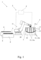
- the manufacturing system 1 shown in the drawings serves for producing a Fiber Metal Laminate component of an airplane.
- such component is part of a structural component of an airplane, in particular part of a fuselage or wing of an airplane.
- the component is part of the outer skin of the fuselage.
- the component is accordingly of half shell shape.
- the manufacturing system 1 comprises a manipulator system 2 with an end effector 3 and a control 4 assigned to the manipulator system 2.
- the control 4 is an electronic control which controls not only the movement of the manipulator system 2 but also the actions of the end effector 3.
- the manufacturing system 1 here and preferably is structured as a robot cell.
- the kind of layers 5, 6 and the stacking sequence depends on the kind of Fiber Metal Laminate material, the resulting component shall be made off.
- the metal layer 5 may be any kind of metal sheet
- the fiber layer 6 may be any kind of fiber sheet, which may be of dry fiber material or preimpregnated fiber material, also known as prepreg.
- the Fiber Metal Laminate component is a so called GLARE ® material (Glass Laminate Aluminium Reinforced Epoxy).
- the metal layer 5 is at least partly an aluminium layer. Other metal materials such as titanium may be applied as well.
- the outer layers of the Fiber Metal Laminate component are metal layers 5.
- the thickness of the metal layers is below 1,0 mm, preferably between 0,2 mm and 0,5 mm, further preferably between 0,3 mm and 0,4 mm. For prevention of corrosion it is anodized. In order to provide good bonding characteristics it is further coated with an appropriate primer.
- the fiber layer 6 may be of prepreg fiber material or dry fiber material, which during manufacturing is in any case unhardened. It may comprise different kind of fibers such as glass fibers, aramid fibers or the like.
- adhesive tape layers can be handled and deposited between two metal layers 5 or between two fiber layers 6 or a fiber layer 6 and a metal layer 5.
- an adhesive tape layer is positioned in the overlapping region in between the two metal layers 5. The adhesive tape layer can provide a sealing between the respective two layers.
- Each stacking cycle comprises picking up a metal layer 5 or a fiber layer 6 or an adhesive tape layer from a respective supply stack 8 according to the respective stacking sequence.
- two supply stacks 8, 9 are provided.
- Both types of layers 5, 6 can also be supplied on one supply stack.
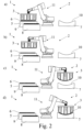
- Whether the metal layer 5 is being picked up from the supply stack 8 or a fiber layer 6 is being picked up from supply stack 9 depends on the stacking sequence which largely depends on the layer structure of the Fiber Metal Laminate component to be manufactured. The picking up of the respective layer is shown in Fig. 2a .
- the picked up a layer 5, 6 is being transported to the mould as shown in Fig. 2b .
- the transportation of the layer 5, 6 is followed the placement of the layer 5, 6 at a deposition surface 10 in the mould 7 according to the stacking sequence which again is followed by depositing the so placed layer 5, 6 onto the deposition surface 10, as shown in Fig. 2d .
- the deposition surface 10 may be the surface of the mould 7 or the surface of the respective layer 5, 6 that has been stacked in the previous stacking cycle. Accordingly the exact location of the deposition surface 10 depends on the stacking sequence. In any case the form of the deposition surface 10 is largely defined by the form of the mould 7.
- the mould 7, respectively the deposition surface 10 may have a convex and/or a concave form.
- the mould 7, respectively the deposition surface 10 may have both convex as well as concave sections, for example when fiber metal laminate components for the airplane sections between the fuselage and the wing are to be produced.
- the layer 5, 6 to be stacked is being deformed by the end effector 3 as to adapt the form of the layer 5, 6 to the form of the deposition surface 10.
- the deposition surface is of concave form, to which the layer 5, 6 is being adapted by the end effector 3.
- the step of deforming the respective layer 5, 6 may take place at any time between picking up the layer 5, 6 and depositing the layer 5, 6.
- the deforming step is being performed while the manipulator system 2 is being moved, in particular during the transporting step.
- it may be advantageous to stop the movement of the manipulator system 2 for the deforming step for example in order to achieve a higher accuracy in deforming.
- the advantages of providing a deforming step has been explained in the general part of the specification. The possibility of preventing cavities between layers 5, 6 becomes especially apparent when looking at Fig. 2c , d.
- the manipulator system 2 it is generally possible for the manipulator system 2 to comprise more than one end effector 3, for example if certain process steps are to be performed in parallel. All explanations given for the one shown end effector 3 are fully applicable to a manipulator system 2 with two or more than two end effectors 3.
- the manipulator system 2 shown in the drawings comprises a manipulator 11, which is being driven by the control 4.
- the manipulator 11 is a robot with sequential axes. It may also be a robot with any kind of other kinematic, for example the kinematic of a portal robot.
- the manipulator 11 may as well be a construction which is tailored to the manufacturing process explained above.
- the end effector 3 preferably comprises a gripping arrangement 12 for gripping the layer 5, 6 during pick up.
- the gripping arrangement 12 includes here and preferably a number of gripping elements 13 which each provide a localized gripping interaction with the respective layer 5, 6.
- the gripping arrangement 12 defines a gripping plane 14, along which the gripping interaction with the respective layer 5, 6 is possible.
- the gripping elements 13 are distributed across the gripping plane 14 of the gripping arrangement 12.
- the gripping arrangement 12 is being activated by the control 4.
- the activation of the gripping arrangement 12 does not only include turning on and off a gripping interaction but also adjusting operating parameters of the end effector 3 as will be noted below.
- the gripping elements 13 are distributed across the gripping plane 14, the gripping elements 13 are being activated separately or in groups by the control 4. With this it is possible to selectively activate the gripping elements 13, for example in order to prevent unused gripping elements 13 to undesirably interact with already deposited layers 5, 6. It is possible to handle layers 5, 6 smaller than the outline of the gripping arrangement 12.
- the gripping arrangement 12 comprises at least one gripping element 13a, here and preferably a number of gripping elements 13a, of a first type and at least one gripping element 13b, here and preferably a number of gripping elements 13b, of a second type.
- the gripping element 13a of the first type provided a floating grip of the layer 5, 6 along its surface such that the gripping forces only act perpendicular to the surface of the layer 5, 6 and are only minimal in the direction along the surface of the layer 5, 6.
- the gripping element 13b of the second type provides a stiff grip of the layer 5, 6.
- at least two gripping elements 13b of the second type are necessary, which are located at a certain distance to each other. With this distance it is possible for the gripping arrangement to provide a support of the layer 5, 6 also in view of possible rotation of the layer 5, 6.
- the gripping elements 13 of the gripping arrangement 12 There are various possibilities possible for realizing the gripping elements 13 of the gripping arrangement 12. Examples are pincer grippers, needle grippers, freezing grippers or the like.
- the gripping elements are suction gripping elements.
- the gripping elements 13a of the first type are Bemulli suction gripping elements, while the gripping elements 13b of the second type are Venturi suction gripping elements.
- the application of suction gripping elements is presently advantageous as damaging of the layers 5, 6 may effectively prevented, as is of particular importance for airplane components.
- the end effector 3 comprises a deformable carrier arrangement 15, which the gripping arrangement 12 is located on.
- the carrier arrangement comprises bendable carrier strips 16 which the gripping elements 13 are located on.
- the end effector 3 also comprises an actuator arrangement 17 for actuator based deforming of the carrier arrangement 15.
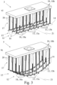
- the actuator arrangement 17 is being driven by the control 4. This becomes a parent from a comparison of Fig. 3a and Fig. 3b .
- Fig. 3 also shows that the actuator arrangement 17 comprises at least two actuators 18, here and preferably a number of actuators 18, that are driven by the control 4.
- the actuators 18 of the actuator arrangement 17 are linear actuators, that are driven by the control 4 respectively.
- the actuators 18 are partly of the type of a pneumatic muscle and partly of the type of a pneumatic piston drive.
- the actuator arrangement 17 comprises at least two actuators 18 of different type.
- the actuators 18 of the type of a pneumatic muscle are denominated with reference number 18a, while the actuators 18 of the type of a pneumatic piston drive are denominated with reference number 18b.
- the actuators 18a of the first type exact pulling forces may be introduced into the carrier arrangement 15, at the same time providing a certain elasticity.
- actuators 18b of the second type pulling forces and pushing forces may be introduced into the carrier arrangement 15, such that the actuators 18b of the second kind provide supporting points for the forces generated by the actuators 18a of the first kind.
- actuators 18a, 18b interacting with each other a high flexibility and at the same time accuracy in deformation of the carrier arrangement 1 and their risk of the gripped layer 5, 6 is possible.
- actuators 18 of different type are especially advantageous as the actuators 18 are each acting on the carrier arrangement 15, here on the carrier strips 16, mainly in a perpendicular direction with respect to the gripping plane 14, which the carrier strips 16 are aligned to.
- the actuators 18 are arranged in one or more rows and are attached to an interface arrangement 19 at their respective one ends and to the carrier arrangement 15, here the carrier strips 16, on their respective other ends.
- At least one of the actuators 18 is provided with a return spring 20 that may be a coil spring aligned to the longitudinal extension of the linear actuator 18.
- the application of the shown gripping arrangement 12 for the proposed manipulator system 2 allows an extraordinary amount of flexibility. This is particularly true because depending from driving the above noted actuators 18 by the control 4 the carrier arrangement 15 may be brought into different forms. This includes convex forms, concave forms and combinations of those. Also the degree of deformation of the carrier arrangement 15 and therewith of the respective layer 5, 6 may be changed on a continuous scale. As the deformation may be achieved actuator based as noted above, it is possible with no effort to change the deformation at any time during production, in particular between two stacking cycles.
- An advantage of the proposed method and the proposed manipulator system 2 is the fact that it is possible to provide the layers 5, 6 to be stacked as flat precut layers in the respective supply stack 8, 9.
- the outlines of the respective layers 5, 6 may vary to each other.
- the outlines of the precut metal layers 5 and the precut fiber layers 6 may vary to each other.
- the end effector 3 handles layers 5, 6 of different width and/or length during the production of the fiber metal laminate component.
- the width and/or the length of the metal layers 5 in comparison to the width, respectively the length of the fiber layers 6, may vary during the production of one fiber metal laminate component from one stacking cycle to the next stacking cycle.
- the surface area of the fiber layers 6 is smaller than the surface area of the metal layers 5. Additionally or alternatively the surface area of different metal layers 5 or different fiber layers 6 may vary from one stacking cycle to the next stacking cycle.
- Another adaption of an operating parameter is that during deforming the layer 5, 6 to be stacked, different gripping elements 13 are being activated by the control 4 depending on the layer 5, 6 being a metal layer 5 or a fiber layer 6. According to the invention it is well possible to activate the gripping elements 13 separately or in groups by the control 4. In particular it is preferred that during transporting and/or deforming of the fiber layers 6 a different number of gripping elements are activated then during transporting and/or forming of the metal layers 5, 6. It may also be pointed out that the surfaces of the layers 5, 6 to be stacked are normally smaller than the surface of the mould 7. Accordingly stacking of the layers 5, 6 means building up a tile structure across the mould surface.
- Fiber Metal Laminate structure The particular advantage of a Fiber Metal Laminate structure is that specific mechanical properties may be set, which mechanical properties may depend on the direction of force introduced into the structure. This may be achieved simply by placing the fiber layers 6 in specific orientations.
- the fibers are oriented homogeneously.
- all fibers are basically aligned to one direction.
- Depositing at least two fiber layers 5, 6 onto each other in different fiber orientations may, however, also be advantageous if the fiber layer 6 is of the type of knitted fabrics of interlaced fabrics or the like. It is preferred that at least one fiber layer 6 is stacked onto another fiber layer 6 such that the fiber orientations of the two layers 6 are offset to each other by 90°. In the manufacturing process this means that the first fiber layer 6 is deposited at a first angle and that the second fiber layer 6 is deposited at a second angle, while the first angle and the second angle are not identical. Preferably, the difference between the two angles is above 10°, preferably above 45°, further preferably 45° and especially preferably 90°.
- the complete ranges of angles for depositing the layers 5, 6 may be realized by the proposed manipulator system 2 simply by turning the end effector 3 via the manipulator 11 accordingly.
- the fiber layer 5 and the metal layer 6 are being deformed in at least two faxsian dimensions. It may even be possible that the fiber layer 5 and the metal layer 6 are being deformed in three faxsian dimensions.
- the fiber layer 5 and the metal layer 6 are being deformed by bending around at least one bending axis, which bending axis is roughly indicated in Fig. 3 .
- the bending axis 21 is arranged basically parallel to the surface of the respective layer 5, 6 and there is basically parallel to the gripping plane 14, as may be taken from Fig. 3 as well.
- the placement of the layer 5, 6 to be stacked, which precedes depositing the layer 5, 6 onto the deposition surface 10 may be performed in various advantageous ways.
- the placement of the layer 5, 6 to be stacked goes along with a layer 5, 6 contacting the deposition surface 10 along a contact line or a contact point.
- the contact line or the contact point is a single contact line or a single contact point. With this, depending on the form of the mould 7, the build up of cavities may be prevented.
- the placement of the layer 5, 6 to be stacked goes along with the layer 5, 6 evenly contacting the full deposition surface. This is shown in Fig. 2 .
- the flat contact between the surface of the layer 5, 6 and the deposition surface 10 prevents the build up of cavities.
- the placement of the layer 5, 6 to be stacked goes along with the layer 5, 6 floating directly above the position surface 10.
- the layer 5, 6 is vaguely dropped onto the deposition surface 10. Due to the very short dropping distance and the above noted adaption of the form of the layer 5, 6 to the form of the deposition surface 10, also with this alternative the build up of cavities is prevented.
- the proposed deforming of the respective layer may be performed in various ways, which may be advantageous depending on the form of the mould 7.
- the deformation of the layer 5, 6 to be stacked by the end effector 3 before its deposition is performed such that the form of the layer 5, 6 is identical to the form of the deposition surface. This is shown in Fig. 2 .
- the deformation of the layer 5, 6 to be stacked by the end effector 3 before its deposition is performed such that the form of the layer 5, 6 at least slightly deviates from the form of the deposition surface 10. This may be advantageous if any friction shall be prevented during the placement of the layer 5, 6 at the deposition surface 10.
- a convex deposition surface 10 this is realized that the deformation of the layer 5, 6 is performed such that the layer 5, 6 is less convex than the deposition surface 10.
- a concave deposition surface 10 ( Fig. 1 ) this may be done by deformation of the layer 5, 6 such that the surface of the layer 5, 6 is more concave than the deposition surface 10.
- this principle may be applied accordingly.
- the stacked up arrangement is preferably being compressed in order to i. a. further reduce possible cavities.
- the stacked up arrangement is then preferably transferred into an autoclave, in which it is being heated under pressure, activating the matrix of the fiber layers 6 as far as those fiber layers 6 are of prepreg material.
- This heat treatment is being performed for 3 to 10 hours under a high pressure of about 10 bar. Subsequent heat or pressure treatments may follow according to the layer material applied. It may be pointed out that if the fiber layers 6 are of dry fiber material they might be impregnated after each placement or the matrix material might be applied to the fiber layers 6 before the autoclave.
- the manipulator system 2 for performing the proposed method is claimed as such.
- the manipulator system 2 comprises an end effector 3 and is controllable by the control 4. All explanations given with respect to the proposed method are fully applicable to the proposed manipulator system 2.
Landscapes
- Engineering & Computer Science (AREA)
- Mechanical Engineering (AREA)
- Robotics (AREA)
- Chemical & Material Sciences (AREA)
- Composite Materials (AREA)
- Moulding By Coating Moulds (AREA)
- Laminated Bodies (AREA)
Description
- The invention is directed to a method for producing a Fiber Metal Laminate component of an airplane according to the general part of
claim 1 as well as to a manipulator system according toclaim 16. - The material class of Fiber Metal Laminate (FML) has increasingly been applied for the realization of airplane components, in particular of structural airplane components. The reason for this is that with Fiber Metal Laminates extraordinary mechanical properties may be achieved with extremely lightweight design. A Fiber Metal Laminate comprises metal layers and fiber layers stacked onto each other and bound by a normally thermoset resin.
- The manufacturing process of Fiber Metal Laminate components of an airplane is complex as the layers to be stacked onto each other are flexible at least as far as the fiber layers are concerned. Due to the flexibility of the layers it is challenging to achieve stable handling processes during stacking up the layers onto each other. Another challenge is to prevent the generation of cavities, when one layer is stacked onto another layer.
- For the reasons noted above the manufacturing process is largely performed manually.
- However, approaches have been made to introduce an automated manufacturing process for Fiber Metal Laminate components of an airplane.
-
US 2012 330453 A1 discloses an automated ply layup system using a robot and an end effector for selecting plies from a kit and placing the plies at predetermined locations on a tool. - The known method (
DE 10 2012 000 508 A1 ), which is the starting point of the invention, relies on a manipulator system with one end effector for handling the metal layers and with a second end effector for handling the fiber layers. With this manipulator system the respective layers are being stacked onto each other in a mould in a stacking sequence. Each stacking cycle comprises picking up a layer from a supply stack, transporting the layer to the mould, placement of the layer at a deposition surface in the mould and depositing the so placed layer onto the deposition surface. - In order to prevent a building up of cavities during stacking up the layers, the layers are being fixed to the mould by electrostatic charging.
- While the known method generally allows automatic manufacturing of Fiber Metal Laminate components of an airplane, the backdraw of this approach is the high complexity of the resulting manufacturing system and as a result the high costs involved with setting up such a manufacturing system.
- It is the objective of the invention to improve the known method as to achieve a stable automated manufacturing process with a manufacturing system of low complexity.
- The above noted objective is achieved for a method according to the general part of
claim 1 by the features of the characterizing part ofclaim 1. - The idea underlying the invention is to adapt the form of the layer to be stacked to the form of the mould, before the respective layer is being deposited. With this it is possible that a flat contact is achieved between the surface of the layer and the surface of the deposition surface. With such contact the buildup of cavities may be prevented or at least effectively be reduced.
- In detail it is proposed that after being picked up from the supply stack and before being deposited onto the position surface the layer to be stacked is being deformed by the end effector as to adapt the form of the layer to the form of the deposition surface. It has been found that the above noted deforming of the layer may be achieved by the end effector itself. This is especially advantageous as no additional tool is necessary for deforming and also as no additional handling step is necessary for adapting the form of the layer to the deposition surface.
- The invention provides improved gripping of the layer to be stacked via a gripping arrangement. It is particularly preferred that the gripping arrangement at least partly provided a floating grip of the layer along its surface such that during the proposed deformation of the layer no undesired mechanical tension is building up within the layer.
- Especially preferred embodiments are directed to deforming the respective layer with low mechanical complexity.
- The idea behind the invention is to pick up and deform the respective layer via one and the same end effector.
- It has been found that especially when using suction gripping elements for the gripping arrangement it is well possible to even use one and the same gripping element to grip a metal layer as well as a fiber layer. Opposite to what is taught in the state of the art it is now possible to handle metal layers and fiber layers with one and the same end effector, such that the respective end effector may be applied in a particularly effective way.
- A further preferred embodiment allows an air pocked free deposition of the respective layer as a completely flat contact may be established between the surface of the layer and the deposition surface.
- However, depending on the design of the mould it may be advantageous that the form of the layer before its deposition at least slightly deviates from the form of the deposition surface. This may prevent the build up of friction between the layer and the deposition surface during placement of the layer into the mould. Such friction may again lead to the build up of the undesired cavities between the layers.
- According to
claim 16, the manipulator system for performing the proposed method is claimed as such. Reference is made to all explanations even regarding the proposed method, as far as those explanations are suitable to describe the manipulator system. - In the following the invention will be described based on an example with reference to the drawings. In the drawings show
- Fig. 1
- a proposed manufacturing system for performing the proposed method,
- Fig. 2
- various steps of the proposed method a) picking up a layer, b) transporting the layer, c) transporting and deforming the layer and d) placement of the layer before its deposition and
- Fig. 3
- the end effector of the manipulator system of
Fig. 1 in its demounted state, a) in a configuration according toFig. 2a and 2b and b) in a configuration according toFig. 2c and 2d . - The
manufacturing system 1 shown in the drawings serves for producing a Fiber Metal Laminate component of an airplane. Preferably, such component is part of a structural component of an airplane, in particular part of a fuselage or wing of an airplane. Here and preferably the component is part of the outer skin of the fuselage. The component is accordingly of half shell shape. - The
manufacturing system 1 comprises amanipulator system 2 with anend effector 3 and acontrol 4 assigned to themanipulator system 2. Thecontrol 4 is an electronic control which controls not only the movement of themanipulator system 2 but also the actions of theend effector 3. Themanufacturing system 1 here and preferably is structured as a robot cell. - During manufacturing at least one
metal layer 5 and at least oneunhardened fiber layer 6 are being stacked onto each other in amould 7 by themanipulator system 2 in a stacking sequence. The kind oflayers metal layer 5 may be any kind of metal sheet, thefiber layer 6 may be any kind of fiber sheet, which may be of dry fiber material or preimpregnated fiber material, also known as prepreg. - It is especially preferred that the Fiber Metal Laminate component is a so called GLARE® material (Glass Laminate Aluminium Reinforced Epoxy). Here the
metal layer 5 is at least partly an aluminium layer. Other metal materials such as titanium may be applied as well. Normally the outer layers of the Fiber Metal Laminate component aremetal layers 5. The thickness of the metal layers is below 1,0 mm, preferably between 0,2 mm and 0,5 mm, further preferably between 0,3 mm and 0,4 mm. For prevention of corrosion it is anodized. In order to provide good bonding characteristics it is further coated with an appropriate primer. - The
fiber layer 6 may be of prepreg fiber material or dry fiber material, which during manufacturing is in any case unhardened. It may comprise different kind of fibers such as glass fibers, aramid fibers or the like. - Additionally to the handling of
metal layers 5 orfiber layers 6 also adhesive tape layers can be handled and deposited between twometal layers 5 or between twofiber layers 6 or afiber layer 6 and ametal layer 5. Preferably, if twometal layers 5 are deposited onto each other partly overlapping, an adhesive tape layer is positioned in the overlapping region in between the twometal layers 5. The adhesive tape layer can provide a sealing between the respective two layers. - Each stacking cycle comprises picking up a
metal layer 5 or afiber layer 6 or an adhesive tape layer from arespective supply stack 8 according to the respective stacking sequence. Here and preferably, twosupply stacks supply stack 8 for providing themetal layer 5 and onesupply stack 9 providing thefiber layer 6. Both types oflayers metal layer 5 is being picked up from thesupply stack 8 or afiber layer 6 is being picked up fromsupply stack 9 depends on the stacking sequence which largely depends on the layer structure of the Fiber Metal Laminate component to be manufactured. The picking up of the respective layer is shown inFig. 2a . - Subsequently within the stacking cycle the picked up a
layer Fig. 2b . The transportation of thelayer layer deposition surface 10 in themould 7 according to the stacking sequence which again is followed by depositing the so placedlayer deposition surface 10, as shown inFig. 2d . Thedeposition surface 10 may be the surface of themould 7 or the surface of therespective layer deposition surface 10 depends on the stacking sequence. In any case the form of thedeposition surface 10 is largely defined by the form of themould 7. - Depending on the fiber metal laminate components to be produced the
mould 7, respectively thedeposition surface 10, may have a convex and/or a concave form. Themould 7, respectively thedeposition surface 10, may have both convex as well as concave sections, for example when fiber metal laminate components for the airplane sections between the fuselage and the wing are to be produced. - It is of particular importance for the invention that after being picked up from the
supply stack deposition surface 10 thelayer end effector 3 as to adapt the form of thelayer deposition surface 10. This is shown inFig. 2c . Here the deposition surface is of concave form, to which thelayer end effector 3. - It may be pointed out that the step of deforming the
respective layer layer layer manipulator system 2 is being moved, in particular during the transporting step. However, it may be advantageous to stop the movement of themanipulator system 2 for the deforming step, for example in order to achieve a higher accuracy in deforming. The advantages of providing a deforming step has been explained in the general part of the specification. The possibility of preventing cavities betweenlayers Fig. 2c , d. - It is generally possible for the
manipulator system 2 to comprise more than oneend effector 3, for example if certain process steps are to be performed in parallel. All explanations given for the one shownend effector 3 are fully applicable to amanipulator system 2 with two or more than twoend effectors 3. - The
manipulator system 2 shown in the drawings comprises amanipulator 11, which is being driven by thecontrol 4. Here and preferably themanipulator 11 is a robot with sequential axes. It may also be a robot with any kind of other kinematic, for example the kinematic of a portal robot. Themanipulator 11 may as well be a construction which is tailored to the manufacturing process explained above. - The
end effector 3 preferably comprises agripping arrangement 12 for gripping thelayer arrangement 12 includes here and preferably a number of gripping elements 13 which each provide a localized gripping interaction with therespective layer arrangement 12 defines a grippingplane 14, along which the gripping interaction with therespective layer plane 14 of thegripping arrangement 12. - The gripping
arrangement 12 is being activated by thecontrol 4. The activation of thegripping arrangement 12 does not only include turning on and off a gripping interaction but also adjusting operating parameters of theend effector 3 as will be noted below. - It is of particular importance that while the gripping elements 13 are distributed across the gripping
plane 14, the gripping elements 13 are being activated separately or in groups by thecontrol 4. With this it is possible to selectively activate the gripping elements 13, for example in order to prevent unused gripping elements 13 to undesirably interact with already depositedlayers layers gripping arrangement 12. - As may be seen from
Fig. 3 the grippingarrangement 12 comprises at least one gripping element 13a, here and preferably a number of gripping elements 13a, of a first type and at least one gripping element 13b, here and preferably a number of gripping elements 13b, of a second type. This generally provides an increase of flexibility of thegripping arrangement 12, as different gripping characteristics may be set by thecontrol 4. In the preferred embodiment shown inFig. 3 the gripping element 13a of the first type provided a floating grip of thelayer layer layer layer gripping arrangement 12 during deformation such that undesired attention within thelayer layer layer layer layer layer - There are various possibilities possible for realizing the gripping elements 13 of the
gripping arrangement 12. Examples are pincer grippers, needle grippers, freezing grippers or the like. Here and preferably however, the gripping elements are suction gripping elements. In particular, the gripping elements 13a of the first type are Bemulli suction gripping elements, while the gripping elements 13b of the second type are Venturi suction gripping elements. The application of suction gripping elements is presently advantageous as damaging of thelayers - As noted above the deformation of the
layer end effector 3 itself. For this theend effector 3 comprises adeformable carrier arrangement 15, which thegripping arrangement 12 is located on. Here and preferably the carrier arrangement comprises bendable carrier strips 16 which the gripping elements 13 are located on. - The
end effector 3 also comprises anactuator arrangement 17 for actuator based deforming of thecarrier arrangement 15. For deforming the grippedlayer actuator arrangement 17 is being driven by thecontrol 4. This becomes a parent from a comparison ofFig. 3a and Fig. 3b . -
Fig. 3 also shows that theactuator arrangement 17 comprises at least two actuators 18, here and preferably a number of actuators 18, that are driven by thecontrol 4. - The realization of the
actuator arrangement 17 is possible in various advantageous ways. Here and preferably the actuators 18 of theactuator arrangement 17 are linear actuators, that are driven by thecontrol 4 respectively. Here and preferably the actuators 18 are partly of the type of a pneumatic muscle and partly of the type of a pneumatic piston drive. Accordingly theactuator arrangement 17 comprises at least two actuators 18 of different type. The actuators 18 of the type of a pneumatic muscle are denominated with reference number 18a, while the actuators 18 of the type of a pneumatic piston drive are denominated with reference number 18b. With the actuators 18a of the first type, exact pulling forces may be introduced into thecarrier arrangement 15, at the same time providing a certain elasticity. With the actuators 18b of the second type pulling forces and pushing forces may be introduced into thecarrier arrangement 15, such that the actuators 18b of the second kind provide supporting points for the forces generated by the actuators 18a of the first kind. With this combination of actuators 18a, 18b interacting with each other a high flexibility and at the same time accuracy in deformation of thecarrier arrangement 1 and their risk of the grippedlayer - Regarding the detailed construction shown in
Fig. 3 the above noted application of actuators 18 of different type is especially advantageous as the actuators 18 are each acting on thecarrier arrangement 15, here on the carrier strips 16, mainly in a perpendicular direction with respect to the grippingplane 14, which the carrier strips 16 are aligned to. The actuators 18 are arranged in one or more rows and are attached to aninterface arrangement 19 at their respective one ends and to thecarrier arrangement 15, here the carrier strips 16, on their respective other ends. At least one of the actuators 18 is provided with areturn spring 20 that may be a coil spring aligned to the longitudinal extension of the linear actuator 18. - Further constructional details regarding the
gripping arrangement 12 may be taken fromUS 2014/0199153 A1 , which goes back on the applicant. - The application of the shown gripping
arrangement 12 for the proposedmanipulator system 2 allows an extraordinary amount of flexibility. This is particularly true because depending from driving the above noted actuators 18 by thecontrol 4 thecarrier arrangement 15 may be brought into different forms. This includes convex forms, concave forms and combinations of those. Also the degree of deformation of thecarrier arrangement 15 and therewith of therespective layer - As a consequence, it is possible to change the
mould 7 for the production of one Fiber Metal Laminate component to anothermould 7 for the production of another Fiber Metal Laminate component with a different geometry of themould 7. This may be done without having to adapt themanipulator system 2 mechanically. In order to produce different Fiber Metal Laminate components changes have only to be made in and/or by thecontrol 4. In particular thecontrol 4 changes the drive movement of the manipulator and/or the drive movement of the actuators 18 and/or the operating parameters of thegripping arrangement 12. - An advantage of the proposed method and the proposed
manipulator system 2 is the fact that it is possible to provide thelayers respective supply stack layers end effector 3 it is not necessary to have thelayers supply stack layers respective layers precut metal layers 5 and theprecut fiber layers 6 may vary to each other. Preferably, theend effector 3 handles layers 5, 6 of different width and/or length during the production of the fiber metal laminate component. The width and/or the length of themetal layers 5 in comparison to the width, respectively the length of the fiber layers 6, may vary during the production of one fiber metal laminate component from one stacking cycle to the next stacking cycle. Preferably, the surface area of the fiber layers 6 is smaller than the surface area of the metal layers 5. Additionally or alternatively the surface area ofdifferent metal layers 5 ordifferent fiber layers 6 may vary from one stacking cycle to the next stacking cycle. - An increase of effectiveness is also achieved by the fact that at least one
metal layer 5 and at least onefiber layer 6, here and preferably allmetal layers 5 and allfiber layers 6, are each being picked up and deformed via one and thesame end effector 3. Accordingly it has been found that generally it is not necessary to havedifferent end effectors 3 for the different layers of the Fiber Metal Laminate component. This is particular true for those layers of above noted GLARE® materials. During manufacturing it is possible to optimize various operating parameters by thecontrol 4. Here and preferably at least one operating parameter of theend effector 3 is being adapted by thecontrol 4 depending on thelayer layer control 4. Another adaption of an operating parameter is that during deforming thelayer control 4 depending on thelayer metal layer 5 or afiber layer 6. According to the invention it is well possible to activate the gripping elements 13 separately or in groups by thecontrol 4. In particular it is preferred that during transporting and/or deforming of the fiber layers 6 a different number of gripping elements are activated then during transporting and/or forming of themetal layers layers mould 7. Accordingly stacking of thelayers - The particular advantage of a Fiber Metal Laminate structure is that specific mechanical properties may be set, which mechanical properties may depend on the direction of force introduced into the structure. This may be achieved simply by placing the fiber layers 6 in specific orientations.
- Preferably, within the fiber layers 6 the fibers are oriented homogeneously. Preferably all fibers are basically aligned to one direction. With this it is easily possible to define the above noted mechanical properties by depositing at least two
fiber layers 6 onto each other in different fiber orientations. - Depositing at least two
fiber layers fiber layer 6 is of the type of knitted fabrics of interlaced fabrics or the like. It is preferred that at least onefiber layer 6 is stacked onto anotherfiber layer 6 such that the fiber orientations of the twolayers 6 are offset to each other by 90°. In the manufacturing process this means that thefirst fiber layer 6 is deposited at a first angle and that thesecond fiber layer 6 is deposited at a second angle, while the first angle and the second angle are not identical. Preferably, the difference between the two angles is above 10°, preferably above 45°, further preferably 45° and especially preferably 90°. The complete ranges of angles for
depositing thelayers manipulator system 2 simply by turning theend effector 3 via themanipulator 11 accordingly. - There may be a different freedom in deformation of the
layers fiber layer 5 and themetal layer 6 are being deformed in at least two kartesian dimensions. It may even be possible that thefiber layer 5 and themetal layer 6 are being deformed in three kartesian dimensions. Here and preferably thefiber layer 5 and themetal layer 6 are being deformed by bending around at least one bending axis, which bending axis is roughly indicated inFig. 3 . Further preferably the bendingaxis 21 is arranged basically parallel to the surface of therespective layer plane 14, as may be taken fromFig. 3 as well. - The placement of the
layer layer deposition surface 10 may be performed in various advantageous ways. In a first preferred embodiment the placement of thelayer layer deposition surface 10 along a contact line or a contact point. Preferably the contact line or the contact point is a single contact line or a single contact point. With this, depending on the form of themould 7, the build up of cavities may be prevented. As an alternative, the placement of thelayer layer Fig. 2 . As the manufacturing system shown in the drawings provides a high accuracy in positioning of theend effector 3, the flat contact between the surface of thelayer deposition surface 10 prevents the build up of cavities. As another alternative the placement of thelayer layer position surface 10. Thelayer deposition surface 10. Due to the very short dropping distance and the above noted adaption of the form of thelayer deposition surface 10, also with this alternative the build up of cavities is prevented. - The proposed deforming of the respective layer may be performed in various ways, which may be advantageous depending on the form of the
mould 7. - In a first preferred embodiment the deformation of the
layer end effector 3 before its deposition is performed such that the form of thelayer Fig. 2 . - It may also be advantageous that the deformation of the
layer end effector 3 before its deposition is performed such that the form of thelayer deposition surface 10. This may be advantageous if any friction shall be prevented during the placement of thelayer deposition surface 10. In case of aconvex deposition surface 10 this is realized that the deformation of thelayer layer deposition surface 10. In case of a concave deposition surface 10 (Fig. 1 ) this may be done by deformation of thelayer layer deposition surface 10. For other designs of themould 7 this principle may be applied accordingly. - After the above noted stacking of the
layers mould 7 the stacked up arrangement is then preferably transferred into an autoclave, in which it is being heated under pressure, activating the matrix of the fiber layers 6 as far as thosefiber layers 6 are of prepreg material. This heat treatment is being performed for 3 to 10 hours under a high pressure of about 10 bar. Subsequent heat or pressure treatments may follow according to the layer material applied. It may be pointed out that if the fiber layers 6 are of dry fiber material they might be impregnated after each placement or the matrix material might be applied to the fiber layers 6 before the autoclave. - According to a second teaching, which is of independent importance, the
manipulator system 2 for performing the proposed method is claimed as such. As noted above, themanipulator system 2 comprises anend effector 3 and is controllable by thecontrol 4. All explanations given with respect to the proposed method are fully applicable to the proposedmanipulator system 2.
Claims (16)
- Method for producing a Fiber Metal Laminate component of an airplane, using a manipulator system (2) with an end effector (3) and a control (4) assigned to the manipulator system (2), wherein at least one metal layer (5) and at least one unhardened fiber layer (6) are being stacked onto each other in a mould (7) by the manipulator system (2) in a stacking sequence, wherein each stacking cycle comprises picking up a metal layer (5) or a fiber layer (6) from a respective supply stack (8, 9) according to the stacking sequence, transporting the layer (5, 6) to the mould (7), placement of the layer (5, 6) at a deposition surface in the mould (7) according to the stacking sequence and depositing the so placed layer (5, 6) onto the deposition surface (10),
characterized in
that after being picked up from the supply stack (8, 9) and before being deposited onto the deposition surface (10), the layer (5, 6) to be stacked is being deformed by the end effector (3) as to adapt the form of the layer (5, 6) to the form of the deposition surface (10) and that at least one metal layer (5) and at least one fiber layer (6) are each being picked up and deformed via one and the same end effector (3) and in that the end effector (3) comprises a number of gripping elements (13) for gripping the layer (5, 6) during pick up, wherein the gripping elements (13) are being activated separately or in groups by the control (4). - Method according to claim 1, characterized in that the manipulator system (2) comprises a manipulator (11), preferably a robot with sequential axes or a portal robot, which manipulator (11) is being driven by the control (4).
- Method according to claim 1 or 2, characterized in that number of gripping elements (13) comprises at least one gripping element (13a) of a first type and at least one gripping element (13b) of a second type.
- Method according to claim 3, characterized in that the gripping element (13a) of the first type provides a floating grip of the layer (5, 6) along its surface and that the gripping element (13b) of the second type provides a stiff grip of the layer (5, 6).
- Method according to claim 3 or 4, characterized in that the gripping elements (13) are suction gripping elements, preferably, that at least one of the gripping elements (13a) is of the type of Bernoulli suction gripping element, and/or, that at least one of the gripping elements (13b) is of the type of Venturi suction gripping element.
- Method according to any one of claims 3 to 5, characterized in that the end effector (3) comprises a deformable carrier arrangement (15), that the gripping arrangement (12) is located on the carrier arrangement (15), that the end effector (3) also comprises an actuator arrangement (17) for actuator based deforming of the carrier arrangement (15) and that for deforming the gripped layer (8, 9) the actuator arrangement (17) is being driven by the control (4), preferably, that the actuator arrangement (17) comprises at least two actuators (18), preferably at least two linear actuators (18), that are driven by the control (4), in particular of the type of a pneumatic muscle (18a) and/or of the type of a pneumatic piston drive (18b), preferably, that the actuator arrangement (17) comprises at least two actuators (18) of different type.
- Method according to any one of the preceding claims, characterized in that the layers (5, 6) to be stacked are provided as flat precut layers (5, 6) in the supply stack (8, 9).
- Method according to any one of claims 3 to 7, characterized in that the gripping elements (13) are being activated separately or in groups by the control (4) in such a way, that unused gripping elements 13 are prevented to undesirably interact with already deposited layers 5, 6 and layers 5, 6 smaller than the outline of the gripping arrangement 12 may be handled.
- Method according to any one of the preceding claims, characterized in that at least one operating parameter of the end effector (3) is being adapted by the control (4) depending of the layer (5, 6) being a metal layer (5) or a fiber layer (6).
- Method according to any one of claims 3 to 9, characterized in that during deforming the layer (5, 6) to be stacked, different gripping elements (13) are being activated by the control (4) depending of the layer (5, 6) being a metal layer (5) or a fiber layer (6).
- Method according to any one of the preceding claims, characterized in that within the fiber layers (6) the fibers are oriented homogeneously, preferably, that all fibers are basically aligned to one direction, and/or, that at least two fiber layers are being deposited onto each other in different fiber orientations.
- Method according to any one of the preceding claims, characterized in that the fiber layer (6) and the metal layer (5) are being deformed in at least two cartesian dimensions, preferably, that the fiber layer (6) and the metal layer (5) are being deformed in three cartesian dimensions, and/or, that the fiber layer (6) and the metal layer (5) are being deformed by bending around at least one bending axis (21), preferably, that the at least one bending axis (21) is arranged basically parallel to the surface of the respective layer (5, 6).
- Method according to any one of the preceding claims, characterized in that the placement of the layer (5, 6) to be stacked goes along with the layer (5, 6) contacting the deposition surface (10) along a contact line or a contact point, or, that the placement of the layer (5, 6) to be stacked goes along with the layer (5, 6) evenly contacting the full deposition surface (10), or, that the placement of the layer (5, 6) to be stacked goes along with the layer (5, 6) floating directly above the deposition surface (10).
- Method according to any one of the preceding claims, characterized in that the deformation of the layer (5, 6) to be stacked by the end effector (3) before its deposition is performed such that the form of the layer (5, 6) is identical to the form of the deposition surface (10).
- Method according to any one of the preceding claims, characterized in that the deformation of the layer (5, 6) to be stacked by the end effector (5) before its deposition is performed such that the form of the layer (5, 6) at least slightly deviates from the form of the deposition surface (10), preferably, that the deformation of the layer (5, 6) to be stacked by the end effector (3) before its deposition is performed such that in case of a convex deposition surface (10) the layer (5, 6) is less convex than the deposition surface (10) and that in case of a concave deposition surface (10) the surface of the layer (5, 6) is more concave than the deposition surface (10).
- Manipulator system for performing the method according to any one of the preceding claims,the manipulator system (2) comprising an end effector (3) and a control (4) assigned to the manipulator system (2),the control (4) being an electronic control which controls not only the movement of the manipulator system (2) but also the actions of the end effector (3),the manipulator system being configured to perform the method according to any one of the preceding claims,wherein the end effector (3) comprises a number of gripping elements (13) for gripping a layer (5, 6) during pick up, wherein the gripping elements (13) are being activated separately or in groups by the control (4).
Applications Claiming Priority (2)
| Application Number | Priority Date | Filing Date | Title |
|---|---|---|---|
| DE102015009177.8A DE102015009177A1 (en) | 2015-07-09 | 2015-07-09 | Method for producing a fiber-metal laminate component of an aircraft |
| PCT/EP2016/065929 WO2017005770A1 (en) | 2015-07-09 | 2016-07-06 | Method for producing a fiber laminate component of an airplane |
Publications (2)
| Publication Number | Publication Date |
|---|---|
| EP3319789A1 EP3319789A1 (en) | 2018-05-16 |
| EP3319789B1 true EP3319789B1 (en) | 2024-12-25 |
Family
ID=56368964
Family Applications (1)
| Application Number | Title | Priority Date | Filing Date |
|---|---|---|---|
| EP16736114.6A Active EP3319789B1 (en) | 2015-07-09 | 2016-07-06 | Method for producing a fiber laminate component of an airplane |
Country Status (8)
| Country | Link |
|---|---|
| US (1) | US11453179B2 (en) |
| EP (1) | EP3319789B1 (en) |
| CN (1) | CN107921716B (en) |
| DE (1) | DE102015009177A1 (en) |
| DK (1) | DK3319789T3 (en) |
| ES (1) | ES3014450T3 (en) |
| RU (1) | RU2752348C2 (en) |
| WO (1) | WO2017005770A1 (en) |
Families Citing this family (27)
| Publication number | Priority date | Publication date | Assignee | Title |
|---|---|---|---|---|
| DE102015009177A1 (en) | 2015-07-09 | 2017-01-12 | Broetje-Automation Gmbh | Method for producing a fiber-metal laminate component of an aircraft |
| GB2543843B (en) * | 2015-10-31 | 2020-04-29 | Loop Tech Ltd | A system for handling flexible materials |
| US10843387B2 (en) * | 2015-12-18 | 2020-11-24 | Teijin Limited | Method of manufacturing a press molding |
| MX2018008586A (en) * | 2016-01-12 | 2019-01-21 | Grabit Inc | METHODS AND SYSTEMS OF COMBINED NEGATIVE PRESSURE AND HANDLING BASED ON MANUFACTURING ELECTROADHESION. |
| DE102016011618A1 (en) | 2016-09-28 | 2018-03-29 | Broetje-Automation Gmbh | end effector |
| JP6821417B2 (en) | 2016-12-16 | 2021-01-27 | 芝浦機械株式会社 | Transfer device and transfer head |
| DE102016125674A1 (en) | 2016-12-23 | 2018-06-28 | Broetje-Automation Gmbh | end effector |
| DE102017203368B4 (en) * | 2017-03-02 | 2023-07-06 | Volkswagen Aktiengesellschaft | Method and device for stiffening metal components using a robot-guided application head |
| JP6856766B2 (en) * | 2017-03-22 | 2021-04-14 | サン−ゴバン グラス フランス | Equipment and methods for capturing, deforming and placing thin glass panes |
| US10843449B2 (en) | 2017-12-14 | 2020-11-24 | The Boeing Company | Method and apparatus for forming composite plies on contoured tool surfaces |
| US10926490B2 (en) * | 2018-04-09 | 2021-02-23 | The Boeing Company | Composite laminate forming apparatus and method therefor |
| AT521384B1 (en) * | 2018-09-20 | 2020-01-15 | Trumpf Maschinen Austria Gmbh & Co Kg | Automated vacuum gripper and method for securely gripping components |
| US12070850B1 (en) * | 2019-05-14 | 2024-08-27 | Amazon Technologies, Inc. | Multi-piston, vacuum gripper assembly |
| CN114423693B (en) * | 2019-06-03 | 2024-03-22 | 萨克米伊莫拉机械合作社合作公司 | Method and system for transferring articles of the ceramic processing industry |
| US12179445B2 (en) | 2019-09-12 | 2024-12-31 | Syddansk Universitet | End effector including resilient members between adjacent holding tools |
| DE102019130375B4 (en) * | 2019-11-11 | 2023-02-16 | Fipa Holding Gmbh | SUCTION CUP ASSEMBLY FOR HANDLING OBJECTS |
| JP2022095538A (en) | 2020-11-18 | 2022-06-28 | ザ・ボーイング・カンパニー | Composite preform assembly method and apparatus |
| NL2027397B1 (en) * | 2021-01-26 | 2022-08-17 | Boeing Co | Composite preform assembly method and apparatus |
| EP4000842B1 (en) | 2020-11-18 | 2025-01-01 | The Boeing Company | Composite preform assembly method and apparatus |
| JP2022187920A (en) * | 2021-06-08 | 2022-12-20 | パナソニックIpマネジメント株式会社 | Assembly system, control device and assembly method |
| CN113459635A (en) * | 2021-07-07 | 2021-10-01 | 北京机科国创轻量化科学研究院有限公司烟台分公司 | Automatic layering device and method for fiber reinforced metal laminate structural member |
| KR102685833B1 (en) * | 2022-03-14 | 2024-07-16 | 주식회사 성일 | A GRP water tank panel forming apparatus |
| CN115339129A (en) * | 2022-07-18 | 2022-11-15 | 曜福精工技术(江苏)有限公司 | End effector for paving and pasting composite material sheet and paving method |
| GB202212181D0 (en) * | 2022-08-22 | 2022-10-05 | Lm Wind Power As | Layup of pre-manufactured elements in a wind turbine blade part mold |
| CN116409044B (en) * | 2023-06-12 | 2023-08-29 | 成都市鸿侠科技有限责任公司 | Aluminum alloy honeycomb glue joint clamp capable of being clamped flexibly |
| CN117416069A (en) * | 2023-11-02 | 2024-01-19 | 常州碳科智能装备有限公司 | Array variable surface engine blade laying equipment and its laying process method |
| US20250162170A1 (en) * | 2023-11-17 | 2025-05-22 | The Boeing Company | Electrorheological Shape Retaining Membrane |
Citations (1)
| Publication number | Priority date | Publication date | Assignee | Title |
|---|---|---|---|---|
| US20120330453A1 (en) * | 2011-06-22 | 2012-12-27 | The Boeing Company | Automated ply layup system |
Family Cites Families (50)
| Publication number | Priority date | Publication date | Assignee | Title |
|---|---|---|---|---|
| US1279500A (en) | 1917-11-19 | 1918-09-24 | Louis H Berry | Automobile jack and lock. |
| US2729040A (en) | 1954-02-10 | 1956-01-03 | Boeing Co | Vacuum chuck jigs |
| US3367764A (en) | 1964-12-15 | 1968-02-06 | Pittsburgh Plate Glass Co | Glass sheet press shaping apparatus with means to adjust the pressing surface curvature |
| US3281107A (en) | 1965-12-15 | 1966-10-25 | Ohio Brass Co | Hydraulic support prop |
| US3734464A (en) | 1971-11-17 | 1973-05-22 | S Bushnell | Control system for multi-stage lift |
| US3865359A (en) | 1972-05-01 | 1975-02-11 | Dbm Industries Ltd | Vacuum apparatus |
| BE791606A (en) | 1972-07-10 | 1973-03-16 | Pilot Pen Co Ltd | PROCESS AND APPARATUS FOR SUCTION AND LIFTING THE UPPER LEAF FROM A PILE OF THIS TYPE |
| US4129328A (en) | 1977-06-20 | 1978-12-12 | Littell Edmund R | Plate handling apparatus with load deflection compensation |
| US4297118A (en) | 1980-03-18 | 1981-10-27 | Ppg Industries, Inc. | Controlling overheating of vacuum mold used to shape glass sheets |
| US4470835A (en) | 1982-11-15 | 1984-09-11 | Ppg Industries, Inc. | Shaping sheets of glass or other deformable material to a complicated curvature |
| US4527783A (en) | 1983-04-26 | 1985-07-09 | Grumman Aerospace Corporation | Universal contoured parts holding fixture |
| US4487623A (en) | 1983-07-18 | 1984-12-11 | Ppg Industries, Inc. | Method of and apparatus for removing sharply bent glass sheets from press bending molds |
| JPS6125778A (en) | 1984-07-09 | 1986-02-04 | 川崎重工業株式会社 | Variable type curved surface plate |
| US4579577A (en) | 1984-12-21 | 1986-04-01 | Ppg Industries, Inc. | Vacuum press mold construction |
| US4775290A (en) | 1986-03-03 | 1988-10-04 | Flow Systems, Inc. | Flexible vacuum gripper |
| DE3629968A1 (en) | 1986-09-03 | 1988-03-10 | Messerschmitt Boelkow Blohm | DEVICE FOR RECEIVING AND DEPOSITING CUTS |
| US4746348A (en) | 1986-12-29 | 1988-05-24 | Ppg Industries, Inc. | Horizontal press bending apparatus and method |
| US4741751A (en) | 1987-01-05 | 1988-05-03 | Ppg Industries, Inc. | Extended surface pressing mold and method of sheet shaping |
| US4806070A (en) | 1987-04-13 | 1989-02-21 | General Electric Company | Article transfer apparatus |
| US4822398A (en) | 1987-08-07 | 1989-04-18 | Mcmaster Harold | Glass bending and tempering apparatus |
| US4806140A (en) | 1987-12-21 | 1989-02-21 | Ppg Industries, Inc. | Adjustable press face |
| DE4210024A1 (en) | 1992-03-27 | 1993-09-30 | Krause Biagosch Gmbh | Separation device for stacked printing sheets for copier machine - uses lifting tool with suction feet incorporated in flexible suction plate with upwards curved side edges |
| US5556505A (en) | 1994-07-05 | 1996-09-17 | Ford Motor Company | Windshield assembly system |
| US5865089A (en) | 1997-09-19 | 1999-02-02 | Langer; John W. | Linear thruster |
| FR2791919B1 (en) * | 1999-04-12 | 2001-06-01 | Plastic Omnium Cie | METHOD FOR MAKING A REINFORCED PLASTIC PART BY OVERMOLDING A REINFORCING SHEET, DEVICE FOR IMPLEMENTING THIS PROCESS AND MANUFACTURING LINE COMPRISING THIS DEVICE |
| US6431623B1 (en) | 1999-06-11 | 2002-08-13 | Honeywell International Inc. | Vacuum device for peeling off thin sheets |
| CA2330612A1 (en) | 2000-12-29 | 2002-06-29 | Alain Bernier | Flexible actuator |
| US6467824B2 (en) | 2001-03-13 | 2002-10-22 | Data I/O Corporation | Floating seal pick and place system and unit therefor |
| DE20112633U1 (en) * | 2001-07-31 | 2002-02-21 | Festo AG & Co, 73734 Esslingen | Handling device, in particular for handling plates and foils |
| DE10152232B4 (en) | 2001-10-20 | 2005-02-17 | Daimlerchrysler Ag | Method and apparatus for automated handling of resin mats in the manufacture of SMC parts |
| US6666127B2 (en) | 2002-05-03 | 2003-12-23 | Muscle Tech Ltd. | Artificial muscle |
| US6868773B2 (en) | 2002-08-13 | 2005-03-22 | Electro Cam Corporation | Fluidic actuator |
| WO2004096083A2 (en) | 2003-04-24 | 2004-11-11 | Arizona Board Of Regents Acting On Behalf Of Arizona State University | Spring-over-muscle actuator |
| WO2004113015A2 (en) | 2003-06-20 | 2004-12-29 | Par Systems, Inc. | Flexible fixture |
| WO2005045259A1 (en) | 2003-11-10 | 2005-05-19 | Hitachi Medical Corporation | Fluid pressure actuator |
| US7134649B2 (en) | 2004-05-27 | 2006-11-14 | The Boeing Company | Conformal vacuum cup apparatus and method |
| US7464548B2 (en) | 2005-11-30 | 2008-12-16 | The Boeing Company | Shape memory alloy linear actuator |
| WO2007102216A1 (en) | 2006-03-08 | 2007-09-13 | Ibiden Co., Ltd. | Apparatus for introduction into degreasing oven and process for producing honeycomb structure |
| NL2000100C2 (en) * | 2006-06-13 | 2007-12-14 | Gtm Consulting B V | Laminate from metal sheets and plastic. |
| DE102006046624A1 (en) | 2006-09-29 | 2008-04-03 | Brötje-Automation GmbH | Method and transport device for transporting objects |
| US8127659B2 (en) | 2007-01-22 | 2012-03-06 | Panasonic Corporation | Compressible fluid pressure actuator driving mechanism and control apparatus thereof |
| DE102007003275B4 (en) | 2007-01-23 | 2013-11-28 | Airbus Operations Gmbh | Shell element as part of an aircraft fuselage |
| DE102008032574A1 (en) * | 2008-07-11 | 2010-01-14 | Brötje-Automation GmbH | Apparatus for use in the manufacture of fiber reinforced components |
| CN102905888B (en) * | 2009-12-18 | 2016-03-09 | 塞特克技术公司 | Give the method for material conductivity used in composite article manufacture and material thereof |
| RU100448U1 (en) * | 2010-08-11 | 2010-12-20 | Михаил Валерьевич Лифшиц | CONSOLE INDUSTRIAL ROBOT FOR PROCESSING SHEET MATERIALS |
| DE102011106214A1 (en) | 2011-06-07 | 2012-12-13 | Brötje-Automation GmbH | end effector |
| DE102012000508A1 (en) | 2012-01-13 | 2013-07-18 | BOB Engineering GmbH Automation und Produktentwicklung | Producing e.g. glass laminate aluminum reinforced epoxy component useful in aircraft construction, comprises arranging aluminum and prepreg webs alternating layers, where prepreg webs are fixed on the aluminum webs by electrostatic charge |
| US9375908B2 (en) * | 2013-05-03 | 2016-06-28 | The Boeing Company | Flexible material transfer devices, flexible vacuum compaction devices, flexible vacuum chucks, and systems and methods including the same |
| US9205558B1 (en) * | 2014-07-16 | 2015-12-08 | Google Inc. | Multiple suction cup control |
| DE102015009177A1 (en) | 2015-07-09 | 2017-01-12 | Broetje-Automation Gmbh | Method for producing a fiber-metal laminate component of an aircraft |
-
2015
- 2015-07-09 DE DE102015009177.8A patent/DE102015009177A1/en active Pending
-
2016
- 2016-07-06 DK DK16736114.6T patent/DK3319789T3/en active
- 2016-07-06 US US15/743,045 patent/US11453179B2/en active Active
- 2016-07-06 ES ES16736114T patent/ES3014450T3/en active Active
- 2016-07-06 RU RU2018104802A patent/RU2752348C2/en active
- 2016-07-06 EP EP16736114.6A patent/EP3319789B1/en active Active
- 2016-07-06 CN CN201680040641.7A patent/CN107921716B/en active Active
- 2016-07-06 WO PCT/EP2016/065929 patent/WO2017005770A1/en not_active Ceased
Patent Citations (1)
| Publication number | Priority date | Publication date | Assignee | Title |
|---|---|---|---|---|
| US20120330453A1 (en) * | 2011-06-22 | 2012-12-27 | The Boeing Company | Automated ply layup system |
Also Published As
| Publication number | Publication date |
|---|---|
| US11453179B2 (en) | 2022-09-27 |
| RU2018104802A (en) | 2019-08-09 |
| ES3014450T3 (en) | 2025-04-22 |
| DK3319789T3 (en) | 2025-03-17 |
| BR112018000154A2 (en) | 2018-09-11 |
| US20180304556A1 (en) | 2018-10-25 |
| DE102015009177A1 (en) | 2017-01-12 |
| EP3319789A1 (en) | 2018-05-16 |
| WO2017005770A1 (en) | 2017-01-12 |
| RU2018104802A3 (en) | 2019-10-29 |
| RU2752348C2 (en) | 2021-07-26 |
| CN107921716B (en) | 2022-03-01 |
| CN107921716A (en) | 2018-04-17 |
Similar Documents
| Publication | Publication Date | Title |
|---|---|---|
| US11453179B2 (en) | Method for producing a fiber metal laminate component of an airplane | |
| US9821474B2 (en) | End effector | |
| EP2660011B1 (en) | Gripping device for manipulating flexible elements | |
| JP7391498B2 (en) | End effector for conveying ply that has a tendency to sag and forming it with a mandrel. | |
| US11007729B2 (en) | Laying die, laying device and method for manufacturing a laying die | |
| EP3867047B1 (en) | System and methods of automated film removal | |
| DE102015107394B4 (en) | Effector, device and method for picking up, handling and/or depositing textile structures | |
| WO2016075424A1 (en) | Improvements to robotic arm end effectors and their use in the preparation and application of production materials | |
| US20160257428A1 (en) | Method of assembling components | |
| US9925670B2 (en) | Method for handling flexible mat-like workpieces | |
| AU2019200074B2 (en) | High resolution vacuum grippers that utilize bi-stable flow valves | |
| EP3970865A1 (en) | Sheet metal member forming method and sheet metal member forming device | |
| US12090715B2 (en) | Caul plates for preforms that undergo pick and placement | |
| Vistein et al. | Automated production of large fibre metal laminate aircraft structure parts | |
| BR112018000154B1 (en) | METHOD FOR THE PRODUCTION OF A FIBER AND METAL LAMINATE COMPONENT OF AN AIRPLANE | |
| US20160001537A1 (en) | Assembly system | |
| US20190337281A1 (en) | Apparatus for handling and locally fixing flat thermoplastic materials | |
| US20250073928A1 (en) | Gripping device and robot having the same | |
| ZHI | DESIGN OF A SOFT GRIPPER FOR PICK AND PLACE APPLICATION |
Legal Events
| Date | Code | Title | Description |
|---|---|---|---|
| STAA | Information on the status of an ep patent application or granted ep patent |
Free format text: STATUS: THE INTERNATIONAL PUBLICATION HAS BEEN MADE |
|
| PUAI | Public reference made under article 153(3) epc to a published international application that has entered the european phase |
Free format text: ORIGINAL CODE: 0009012 |
|
| STAA | Information on the status of an ep patent application or granted ep patent |
Free format text: STATUS: REQUEST FOR EXAMINATION WAS MADE |
|
| 17P | Request for examination filed |
Effective date: 20171220 |
|
| AK | Designated contracting states |
Kind code of ref document: A1 Designated state(s): AL AT BE BG CH CY CZ DE DK EE ES FI FR GB GR HR HU IE IS IT LI LT LU LV MC MK MT NL NO PL PT RO RS SE SI SK SM TR |
|
| AX | Request for extension of the european patent |
Extension state: BA ME |
|
| DAV | Request for validation of the european patent (deleted) | ||
| DAX | Request for extension of the european patent (deleted) | ||
| STAA | Information on the status of an ep patent application or granted ep patent |
Free format text: STATUS: EXAMINATION IS IN PROGRESS |
|
| 17Q | First examination report despatched |
Effective date: 20210512 |
|
| GRAP | Despatch of communication of intention to grant a patent |
Free format text: ORIGINAL CODE: EPIDOSNIGR1 |
|
| STAA | Information on the status of an ep patent application or granted ep patent |
Free format text: STATUS: GRANT OF PATENT IS INTENDED |
|
| INTG | Intention to grant announced |
Effective date: 20240430 |
|
| GRAJ | Information related to disapproval of communication of intention to grant by the applicant or resumption of examination proceedings by the epo deleted |
Free format text: ORIGINAL CODE: EPIDOSDIGR1 |
|
| STAA | Information on the status of an ep patent application or granted ep patent |
Free format text: STATUS: EXAMINATION IS IN PROGRESS |
|
| GRAP | Despatch of communication of intention to grant a patent |
Free format text: ORIGINAL CODE: EPIDOSNIGR1 |
|
| STAA | Information on the status of an ep patent application or granted ep patent |
Free format text: STATUS: GRANT OF PATENT IS INTENDED |
|
| INTC | Intention to grant announced (deleted) | ||
| INTG | Intention to grant announced |
Effective date: 20240927 |
|
| GRAS | Grant fee paid |
Free format text: ORIGINAL CODE: EPIDOSNIGR3 |
|
| GRAA | (expected) grant |
Free format text: ORIGINAL CODE: 0009210 |
|
| STAA | Information on the status of an ep patent application or granted ep patent |
Free format text: STATUS: THE PATENT HAS BEEN GRANTED |
|
| AK | Designated contracting states |
Kind code of ref document: B1 Designated state(s): AL AT BE BG CH CY CZ DE DK EE ES FI FR GB GR HR HU IE IS IT LI LT LU LV MC MK MT NL NO PL PT RO RS SE SI SK SM TR |
|
| REG | Reference to a national code |
Ref country code: GB Ref legal event code: FG4D |
|
| REG | Reference to a national code |
Ref country code: CH Ref legal event code: EP |
|
| REG | Reference to a national code |
Ref country code: DE Ref legal event code: R096 Ref document number: 602016090728 Country of ref document: DE |
|
| REG | Reference to a national code |
Ref country code: IE Ref legal event code: FG4D |
|
| REG | Reference to a national code |
Ref country code: NL Ref legal event code: FP |
|
| REG | Reference to a national code |
Ref country code: DK Ref legal event code: T3 Effective date: 20250311 |
|
| REG | Reference to a national code |
Ref country code: LT Ref legal event code: MG9D |
|
| PG25 | Lapsed in a contracting state [announced via postgrant information from national office to epo] |
Ref country code: FI Free format text: LAPSE BECAUSE OF FAILURE TO SUBMIT A TRANSLATION OF THE DESCRIPTION OR TO PAY THE FEE WITHIN THE PRESCRIBED TIME-LIMIT Effective date: 20241225 |
|
| PG25 | Lapsed in a contracting state [announced via postgrant information from national office to epo] |
Ref country code: BG Free format text: LAPSE BECAUSE OF FAILURE TO SUBMIT A TRANSLATION OF THE DESCRIPTION OR TO PAY THE FEE WITHIN THE PRESCRIBED TIME-LIMIT Effective date: 20241225 |
|
| REG | Reference to a national code |
Ref country code: ES Ref legal event code: FG2A Ref document number: 3014450 Country of ref document: ES Kind code of ref document: T3 Effective date: 20250422 |
|
| PG25 | Lapsed in a contracting state [announced via postgrant information from national office to epo] |
Ref country code: NO Free format text: LAPSE BECAUSE OF FAILURE TO SUBMIT A TRANSLATION OF THE DESCRIPTION OR TO PAY THE FEE WITHIN THE PRESCRIBED TIME-LIMIT Effective date: 20250325 |
|
| PG25 | Lapsed in a contracting state [announced via postgrant information from national office to epo] |
Ref country code: LV Free format text: LAPSE BECAUSE OF FAILURE TO SUBMIT A TRANSLATION OF THE DESCRIPTION OR TO PAY THE FEE WITHIN THE PRESCRIBED TIME-LIMIT Effective date: 20241225 Ref country code: GR Free format text: LAPSE BECAUSE OF FAILURE TO SUBMIT A TRANSLATION OF THE DESCRIPTION OR TO PAY THE FEE WITHIN THE PRESCRIBED TIME-LIMIT Effective date: 20250326 |
|
| PG25 | Lapsed in a contracting state [announced via postgrant information from national office to epo] |
Ref country code: RS Free format text: LAPSE BECAUSE OF FAILURE TO SUBMIT A TRANSLATION OF THE DESCRIPTION OR TO PAY THE FEE WITHIN THE PRESCRIBED TIME-LIMIT Effective date: 20250325 |
|
| REG | Reference to a national code |
Ref country code: AT Ref legal event code: MK05 Ref document number: 1753823 Country of ref document: AT Kind code of ref document: T Effective date: 20241225 |
|
| PG25 | Lapsed in a contracting state [announced via postgrant information from national office to epo] |
Ref country code: SM Free format text: LAPSE BECAUSE OF FAILURE TO SUBMIT A TRANSLATION OF THE DESCRIPTION OR TO PAY THE FEE WITHIN THE PRESCRIBED TIME-LIMIT Effective date: 20241225 |
|
| PG25 | Lapsed in a contracting state [announced via postgrant information from national office to epo] |
Ref country code: PL Free format text: LAPSE BECAUSE OF FAILURE TO SUBMIT A TRANSLATION OF THE DESCRIPTION OR TO PAY THE FEE WITHIN THE PRESCRIBED TIME-LIMIT Effective date: 20241225 |
|
| PG25 | Lapsed in a contracting state [announced via postgrant information from national office to epo] |
Ref country code: IS Free format text: LAPSE BECAUSE OF FAILURE TO SUBMIT A TRANSLATION OF THE DESCRIPTION OR TO PAY THE FEE WITHIN THE PRESCRIBED TIME-LIMIT Effective date: 20250425 |
|
| PG25 | Lapsed in a contracting state [announced via postgrant information from national office to epo] |
Ref country code: PT Free format text: LAPSE BECAUSE OF FAILURE TO SUBMIT A TRANSLATION OF THE DESCRIPTION OR TO PAY THE FEE WITHIN THE PRESCRIBED TIME-LIMIT Effective date: 20250428 |
|
| PG25 | Lapsed in a contracting state [announced via postgrant information from national office to epo] |
Ref country code: EE Free format text: LAPSE BECAUSE OF FAILURE TO SUBMIT A TRANSLATION OF THE DESCRIPTION OR TO PAY THE FEE WITHIN THE PRESCRIBED TIME-LIMIT Effective date: 20241225 |
|
| PG25 | Lapsed in a contracting state [announced via postgrant information from national office to epo] |
Ref country code: AT Free format text: LAPSE BECAUSE OF FAILURE TO SUBMIT A TRANSLATION OF THE DESCRIPTION OR TO PAY THE FEE WITHIN THE PRESCRIBED TIME-LIMIT Effective date: 20241225 Ref country code: RO Free format text: LAPSE BECAUSE OF FAILURE TO SUBMIT A TRANSLATION OF THE DESCRIPTION OR TO PAY THE FEE WITHIN THE PRESCRIBED TIME-LIMIT Effective date: 20241225 |
|
| PG25 | Lapsed in a contracting state [announced via postgrant information from national office to epo] |
Ref country code: SK Free format text: LAPSE BECAUSE OF FAILURE TO SUBMIT A TRANSLATION OF THE DESCRIPTION OR TO PAY THE FEE WITHIN THE PRESCRIBED TIME-LIMIT Effective date: 20241225 |
|
| PG25 | Lapsed in a contracting state [announced via postgrant information from national office to epo] |
Ref country code: CZ Free format text: LAPSE BECAUSE OF FAILURE TO SUBMIT A TRANSLATION OF THE DESCRIPTION OR TO PAY THE FEE WITHIN THE PRESCRIBED TIME-LIMIT Effective date: 20241225 |
|
| PG25 | Lapsed in a contracting state [announced via postgrant information from national office to epo] |
Ref country code: IT Free format text: LAPSE BECAUSE OF FAILURE TO SUBMIT A TRANSLATION OF THE DESCRIPTION OR TO PAY THE FEE WITHIN THE PRESCRIBED TIME-LIMIT Effective date: 20241225 |
|
| PGFP | Annual fee paid to national office [announced via postgrant information from national office to epo] |
Ref country code: NL Payment date: 20250721 Year of fee payment: 10 |
|
| PG25 | Lapsed in a contracting state [announced via postgrant information from national office to epo] |
Ref country code: SE Free format text: LAPSE BECAUSE OF FAILURE TO SUBMIT A TRANSLATION OF THE DESCRIPTION OR TO PAY THE FEE WITHIN THE PRESCRIBED TIME-LIMIT Effective date: 20241225 |
|
| REG | Reference to a national code |
Ref country code: DE Ref legal event code: R097 Ref document number: 602016090728 Country of ref document: DE |
|
| PGFP | Annual fee paid to national office [announced via postgrant information from national office to epo] |
Ref country code: ES Payment date: 20250826 Year of fee payment: 10 |
|
| PGFP | Annual fee paid to national office [announced via postgrant information from national office to epo] |
Ref country code: DK Payment date: 20250725 Year of fee payment: 10 Ref country code: DE Payment date: 20250723 Year of fee payment: 10 |
|
| PGFP | Annual fee paid to national office [announced via postgrant information from national office to epo] |
Ref country code: GB Payment date: 20250722 Year of fee payment: 10 |
|
| PLBE | No opposition filed within time limit |
Free format text: ORIGINAL CODE: 0009261 |
|
| STAA | Information on the status of an ep patent application or granted ep patent |
Free format text: STATUS: NO OPPOSITION FILED WITHIN TIME LIMIT |
|
| REG | Reference to a national code |
Ref country code: CH Ref legal event code: L10 Free format text: ST27 STATUS EVENT CODE: U-0-0-L10-L00 (AS PROVIDED BY THE NATIONAL OFFICE) Effective date: 20251105 |
|
| 26N | No opposition filed |
Effective date: 20250926 |
|
| REG | Reference to a national code |
Ref country code: CH Ref legal event code: H13 Free format text: ST27 STATUS EVENT CODE: U-0-0-H10-H13 (AS PROVIDED BY THE NATIONAL OFFICE) Effective date: 20260224 |
|
| PG25 | Lapsed in a contracting state [announced via postgrant information from national office to epo] |
Ref country code: LU Free format text: LAPSE BECAUSE OF NON-PAYMENT OF DUE FEES Effective date: 20250706 |
|
| REG | Reference to a national code |
Ref country code: BE Ref legal event code: MM Effective date: 20250731 |
|
| PG25 | Lapsed in a contracting state [announced via postgrant information from national office to epo] |
Ref country code: HR Free format text: LAPSE BECAUSE OF FAILURE TO SUBMIT A TRANSLATION OF THE DESCRIPTION OR TO PAY THE FEE WITHIN THE PRESCRIBED TIME-LIMIT Effective date: 20241225 |
|
| PG25 | Lapsed in a contracting state [announced via postgrant information from national office to epo] |
Ref country code: BE Free format text: LAPSE BECAUSE OF NON-PAYMENT OF DUE FEES Effective date: 20250731 |
|
| PG25 | Lapsed in a contracting state [announced via postgrant information from national office to epo] |
Ref country code: FR Free format text: LAPSE BECAUSE OF NON-PAYMENT OF DUE FEES Effective date: 20250731 |
|
| PG25 | Lapsed in a contracting state [announced via postgrant information from national office to epo] |
Ref country code: CH Free format text: LAPSE BECAUSE OF NON-PAYMENT OF DUE FEES Effective date: 20250731 |