EP3319684B1 - Medical tools for gaining access to extravascular spaces - Google Patents
Medical tools for gaining access to extravascular spaces Download PDFInfo
- Publication number
- EP3319684B1 EP3319684B1 EP16741761.7A EP16741761A EP3319684B1 EP 3319684 B1 EP3319684 B1 EP 3319684B1 EP 16741761 A EP16741761 A EP 16741761A EP 3319684 B1 EP3319684 B1 EP 3319684B1
- Authority
- EP
- European Patent Office
- Prior art keywords
- guide member
- tool
- tunneling
- handle
- tunneling member
- Prior art date
- Legal status (The legal status is an assumption and is not a legal conclusion. Google has not performed a legal analysis and makes no representation as to the accuracy of the status listed.)
- Active
Links
Images





Classifications
-
- A—HUMAN NECESSITIES
- A61—MEDICAL OR VETERINARY SCIENCE; HYGIENE
- A61B—DIAGNOSIS; SURGERY; IDENTIFICATION
- A61B17/00—Surgical instruments, devices or methods
- A61B17/32—Surgical cutting instruments
-
- A—HUMAN NECESSITIES
- A61—MEDICAL OR VETERINARY SCIENCE; HYGIENE
- A61B—DIAGNOSIS; SURGERY; IDENTIFICATION
- A61B17/00—Surgical instruments, devices or methods
- A61B17/34—Trocars; Puncturing needles
- A61B17/3468—Trocars; Puncturing needles for implanting or removing devices, e.g. prostheses, implants, seeds, wires
-
- A—HUMAN NECESSITIES
- A61—MEDICAL OR VETERINARY SCIENCE; HYGIENE
- A61B—DIAGNOSIS; SURGERY; IDENTIFICATION
- A61B17/00—Surgical instruments, devices or methods
- A61B17/34—Trocars; Puncturing needles
- A61B17/3415—Trocars; Puncturing needles for introducing tubes or catheters, e.g. gastrostomy tubes, drain catheters
-
- A—HUMAN NECESSITIES
- A61—MEDICAL OR VETERINARY SCIENCE; HYGIENE
- A61N—ELECTROTHERAPY; MAGNETOTHERAPY; RADIATION THERAPY; ULTRASOUND THERAPY
- A61N1/00—Electrotherapy; Circuits therefor
- A61N1/02—Details
- A61N1/04—Electrodes
- A61N1/05—Electrodes for implantation or insertion into the body, e.g. heart electrode
- A61N1/056—Transvascular endocardial electrode systems
- A61N1/0563—Transvascular endocardial electrode systems specially adapted for defibrillation or cardioversion
-
- A—HUMAN NECESSITIES
- A61—MEDICAL OR VETERINARY SCIENCE; HYGIENE
- A61N—ELECTROTHERAPY; MAGNETOTHERAPY; RADIATION THERAPY; ULTRASOUND THERAPY
- A61N1/00—Electrotherapy; Circuits therefor
- A61N1/18—Applying electric currents by contact electrodes
- A61N1/32—Applying electric currents by contact electrodes alternating or intermittent currents
- A61N1/36—Applying electric currents by contact electrodes alternating or intermittent currents for stimulation
- A61N1/372—Arrangements in connection with the implantation of stimulators
-
- A—HUMAN NECESSITIES
- A61—MEDICAL OR VETERINARY SCIENCE; HYGIENE
- A61B—DIAGNOSIS; SURGERY; IDENTIFICATION
- A61B17/00—Surgical instruments, devices or methods
- A61B17/00234—Surgical instruments, devices or methods for minimally invasive surgery
- A61B2017/00238—Type of minimally invasive operation
- A61B2017/00243—Type of minimally invasive operation cardiac
-
- A—HUMAN NECESSITIES
- A61—MEDICAL OR VETERINARY SCIENCE; HYGIENE
- A61B—DIAGNOSIS; SURGERY; IDENTIFICATION
- A61B17/00—Surgical instruments, devices or methods
- A61B2017/0042—Surgical instruments, devices or methods with special provisions for gripping
- A61B2017/00424—Surgical instruments, devices or methods with special provisions for gripping ergonomic, e.g. fitting in fist
-
- A—HUMAN NECESSITIES
- A61—MEDICAL OR VETERINARY SCIENCE; HYGIENE
- A61B—DIAGNOSIS; SURGERY; IDENTIFICATION
- A61B17/00—Surgical instruments, devices or methods
- A61B17/32—Surgical cutting instruments
- A61B2017/320044—Blunt dissectors
-
- A—HUMAN NECESSITIES
- A61—MEDICAL OR VETERINARY SCIENCE; HYGIENE
- A61B—DIAGNOSIS; SURGERY; IDENTIFICATION
- A61B17/00—Surgical instruments, devices or methods
- A61B17/32—Surgical cutting instruments
- A61B2017/320052—Guides for cutting instruments
-
- A—HUMAN NECESSITIES
- A61—MEDICAL OR VETERINARY SCIENCE; HYGIENE
- A61B—DIAGNOSIS; SURGERY; IDENTIFICATION
- A61B17/00—Surgical instruments, devices or methods
- A61B17/32—Surgical cutting instruments
- A61B2017/320056—Tunnelers
-
- A—HUMAN NECESSITIES
- A61—MEDICAL OR VETERINARY SCIENCE; HYGIENE
- A61B—DIAGNOSIS; SURGERY; IDENTIFICATION
- A61B90/00—Instruments, implements or accessories specially adapted for surgery or diagnosis and not covered by any of the groups A61B1/00 - A61B50/00, e.g. for luxation treatment or for protecting wound edges
- A61B90/08—Accessories or related features not otherwise provided for
- A61B2090/0807—Indication means
- A61B2090/0811—Indication means for the position of a particular part of an instrument with respect to the rest of the instrument, e.g. position of the anvil of a stapling instrument
-
- A—HUMAN NECESSITIES
- A61—MEDICAL OR VETERINARY SCIENCE; HYGIENE
- A61N—ELECTROTHERAPY; MAGNETOTHERAPY; RADIATION THERAPY; ULTRASOUND THERAPY
- A61N1/00—Electrotherapy; Circuits therefor
- A61N1/02—Details
- A61N1/04—Electrodes
- A61N1/05—Electrodes for implantation or insertion into the body, e.g. heart electrode
-
- A—HUMAN NECESSITIES
- A61—MEDICAL OR VETERINARY SCIENCE; HYGIENE
- A61N—ELECTROTHERAPY; MAGNETOTHERAPY; RADIATION THERAPY; ULTRASOUND THERAPY
- A61N1/00—Electrotherapy; Circuits therefor
- A61N1/02—Details
- A61N1/04—Electrodes
- A61N1/05—Electrodes for implantation or insertion into the body, e.g. heart electrode
- A61N1/0504—Subcutaneous electrodes
Definitions
- the present disclosure pertains to tools and associated methods for safely gaining access to extravascular spaces, and more particularly to those suited to safely gain access into a sub-sternal space for the positioning of a medical device therein.
- Implantable medical electrical leads included in systems that are known in the art for delivering cardiac therapy and/or for providing cardiac monitoring, are often implanted transvenously within a heart of a patient. But extravascular implant sites may be preferred, for example, in those patients where vascular access is difficult, or because transvenous leads can become fibrosed in the heart over time, which makes lead revision and extraction procedures challenging.
- US 2014/330208 A1 relates to systems and methods for implanting a medical electrical lead.
- this disclosure provides tools and implant techniques utilizing such tools to gain access and implant a lead within extravascular spaces.
- this disclosure provides a tool for creating a sub-sternal tunnel in a patient.
- the tool comprises a relatively straight guide member extending from a first end thereof to a second end thereof, a tunneling member extending from a first end thereof to a tip thereof, the tunneling member extending alongside and coplanar with the guide member, the first end of the tunneling member and the first end of the guide member being joined together, and a handle coupled to the guide member.
- handle for a tunneling tool comprises a guide member extending from a first end to a second end, an attachment feature configured to reversibly secure the handle to a first end of a tunneling member so that the secured tunneling member extends alongside and coplanar with the guide member, and a gripping portion located in proximity to the attachment feature and the first end of the guide member.
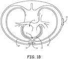
- FIGS 1A-B are schematics showing an exemplary extravascular implant of an exemplary system 10 that includes a pulse generator 14 and an implantable medical electrical lead 16 coupled thereto.
- Pulse generator 14 is shown implanted subcutaneously on the left mid-axillary of a patient 12, superficially of the patient's ribcage.
- Pulse generator 14 further includes a connector module by which lead 16 is electrically coupled to the electronics contained therein, for example, by electrical contacts contained within the connector module and a corresponding hermetically sealed feedthrough assembly, such as is known in the art.
- the conductive material of device housing may be employed as an electrode, for example, to provide the aforementioned therapy in conjunction with one or more pace/sense electrodes 22, 26 and/or a defibrillation electrode 24 of lead 16, which is shown implanted in a sub-sternal space 3, for example, within the loose connective tissue and/or sub-sternal musculature of the anterior mediastinum.
- Lead 16 may have any of a number of configurations. For example, lead 16 may include more or fewer pace/sense electrodes.
- lead 16 may include more than one defibrillation electrode 24 and/or have a defibrillation electrode that is formed of multiple segments. Examples of leads with multiple defibrillation electrodes and/or segments are described in commonly assigned, co-pending U.S. Patent Publication No. 2015/0306375 (Marshall et al. ), U.S. Patent Publication No. 2015/0306410 (Marshall et al. ) and U.S. Patent Publication No. 2016/0158567 (Marshall et al. ).
- the sub-sternal space 3 may be viewed as being bounded laterally by pleurae 39 that enclose the patient's lungs, posteriorly by the pericardial sac 15 that encloses the patient's heart 6, and anteriorly by the sternum 13.
- the anterior wall of the anterior mediastinum may also be formed by the transversus thoracis and one or more costal cartilages.
- FIG. 1A and 1B are described in the context of the distal portion of lead 16 being placed within the sub-sternal space 3, in other embodiments, the tools and implant techniques described herein may be used to implant a distal portion of the lead 16 at other locations outside the heart. In one example, the tools may be used to place the distal portion of lead 16 intra-pericardially via a percutaneous subxiphoid approach.
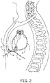
- FIG 2 is a schematic showing an access site A for making a passageway between a patient's diaphragm 19 and xiphoid process 20 of sternum 13, for example, to create a sub-sternal tunnel in which to position a medical device, such as medical electrical lead 16.
- a medical device such as medical electrical lead 16.
- an operator may open a passageway between diaphragmatic attachments 18 and diaphragm 19, for example, by blunt dissection, in which the operator may employ a tunneling tool, for example, the Medtronic® Model 6996T, to both create the passageway and then form a sub-sternal tunnel (e.g. along the dotted line of Figure 2 ).
- a tunneling tool for example, the Medtronic® Model 6996T
- tools and associated methods disclosed herein are configured to help an operator gain the desired sub-sternal access and create a space in which to position a medical device, such as medical electrical lead 16, in a more controlled fashion that mitigates the risk of injuring bodily organs.
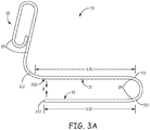
- Figure 3A is a plan view of a tool 30 for gaining sub-sternal access and creating a sub-sternal tunnel in a patient, according to some embodiments.
- Figure 3A illustrates tool 30 including a relatively straight guide member 31 and a tunneling member 32, which are joined together at first ends 311, 321 thereof.
- Guide member 31 is shown extending over a length L31, from first end 311 to a second end thereof 312.
- Tunneling member 32 is shown extending, in the same direction, over a length L32, from first end 321 to a blunt tip 322 thereof.
- Tool 30 also includes a handle 35, which is shown coupled to second end 312 of guide member 31.
- handle 35, guide member 31, and tunneling member 32 are all formed from a single rod 39, for example, a relatively rigid medical grade polymer rod or a medical grade metal rod.
- rod 39 may be formed of 300 series stainless steel having a circular cross-section, which may have a diameter in the range from approximately 0.1 inch (2.5 mm) to approximately 0.14 inch (3.5 mm), for example, approximately 0.12 inch (3.1 mm).
- blunt tip 322 of tunneling member 32 and second end 312 of guide member 31 are biased toward one another, as indicated by arrows B, for example, by an elasticity of rod 39.
- tool 30 may be formed from multiple components, wherein guide member 31 may be biased toward tunneling member 32, and/or tunneling member 32 may be biased toward guide member 31. Furthermore, one or both of guide member 31 and tunneling member 32 may have a non-circular cross-section, in some alternate embodiments.
- length L32 of tunneling member 32 is less than length L31 of guide member 31.
- the difference in lengths L31, L32 of guide member 31 and tunneling member 32 is useful to control an angle of entry through an incision site IS of a patient, for example, as illustrated in Figure 3B . Controlling the angle of entry can mitigate the risk of penetrating too far posterior and injuring sub-sternal structures or the chest cavity.
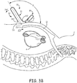
- Figure 3B is a schematic depicting tool 30 positioned for insertion through incision site IS and into a body of a patient. Incision site IS is located in proximity to xiphoid process 20 of sternum 13, for the above-described access to substernal space 3, between diaphragmatic attachments 18 and diaphragm 19 ( Figure 2 ).
- Figure 3B illustrates guide member 31 and tunneling member 32 of tool 30 oriented at an obtuse angle ⁇ relative to a superior extent of sternum 13 from incision site IS, so that guide member second end 312 will abut a location E, for example, an epidermal location, as the operator inserts blunt tip 322 of tunneling member 32 through incision site IS.
- the configuration of tool 30 forces the operator to rotate tunneling member 32 and guide member 31 in an inferior direction, per arrow INF, in order to insert tunneling member blunt tip 322 through incision site IS, thereby keeping the operator from pushing blunt tip 322 too deep or in a wrong direction.
- tunneling member length L32 may be approximately equal to guide member length L31, in which case, the operator need not orient tool 30 at obtuse angle ⁇ for second end 312 to abut location E, but rather approximately orthogonal to the superior extent of sternum 13 from xiphoid process 20, prior to rotating tool 30 in the inferior direction to insert blunt tip 322 through incision site IS.
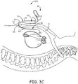
- Figure 3C shows the extent of guide member 31 aligned along sternum 13, outside the patient's body, to help the operator in advancing tunneling member 32, once tip 322 is inserted, in a proper superior direction, per arrow SUP, and thereby creating the sub-sternal tunnel.
- the bias of blunt tip 322 toward guide member 31 can cause blunt tip 322 to 'ride' adjacent an inside surface of sternum 13 during the superior advancement thereof as an additional aid to the operator.
- second end 312 of guide member 31 may in some instances be rounded such that it easily slides over the skin without poking while traversing in the superior direction.
- tool 30 may include an optional marker at a location 302 on guide member 31 that is approximately aligned with blunt tip 322 of tunneling member 32 to provide an indicator that the operator may reference relative to external landmarks of the patient's body to determine the position of tip 322 beneath sternum 13 and thus stop superior advancement at a desired sub-sternal location.
- tunneling member 32 and either all or just the marker of guide member 31 are radiopaque, and the operator uses fluoroscopy to monitor the relative locations of tunneling and guide members 32, 31 while advancing blunt tip 322 beneath sternum 13.
- Figure 3C shows tool 30 as part of a system 370 that also includes an introducer sheath 70, according to some embodiments, wherein sheath 70 includes a lumen (not shown).
- the lumen of sheath 70 includes a proximal opening located at a proximal end 71 of sheath 70, and a distal opening located at a distal end 72 of sheath, and is sized to receive passage of a medical device therethrough, for example, lead 16 ( Figures 1A-B ).
- Figure 3C illustrates introducer sheath 70 mounted on tool guide member 31, for example, having been mounted prior to insertion and advancement of tunneling member 32.
- sheath 70 is configured to slideably engage with guide member 31 and tunneling member 32, and has a flexibility to track around the bend of tool 30 that joins first ends 311, 321 of the guide and tunneling members 31, 32 together, so that, once the operator has advanced tunneling member 32, as shown, to create the sub-sternal tunnel, the operator can slide sheath 70 through incision site IS and along tunneling member 32 into the tunnel, while leaving sheath proximal end 71 external at incision site IS.
- sheath 70 within the sub-sternal tunnel
- the operator may pass a medical device, such as the above described lead 16, through the sheath lumen, via the proximal opening thereof at sheath proximal end 71.
- the operator then removes sheath 70 from the body, leaving lead 16 within the sub-sternal tunnel, for example, by slitting or splitting sheath 70 from around lead, according to some embodiments and methods.
- sheath 70 may include an open channel that extends alongside the lumen thereof and that allows for sheath 70 to slideably engage with tunneling member 32, from tunneling member first end 321 in proximity to incision site IS, after tunneling member 32 has created the sub-sternal tunnel.
- An example of an open channel sheath is described in detail in commonly assigned United States Patent Application No. 2015/0133953 .
- sheath 70 may be mounted on tunneling member 32 prior to the insertion of tunneling member tip 322 through incision site IS such that sheath 70 is maneuvered and advanced along with tunneling member 32 as the sub-sternal tunnel is created.
- sheath 70 may be inserted into the sub-sternal tunnel after tool 30 is removed from the patient's body, or the medical device may be inserted into the tunnel without need for any sheath.
- Figure 4A is a plan view of a tool 40, according to an alternate embodiment.
- Figure 4A illustrates tool 40, like tool 30, including a relatively straight guide member 41 and a tunneling member 42, which are joined together at first ends 411, 421 thereof, and wherein guide and tunneling members 41, 42 extend from respective first ends 411, 421 in the same direction, alongside and coplanar with one another.
- tunneling member 42 includes a blunt tip 422, a handle 45 joined to a second end 412 of guide member 41, and handle 45, guide member 41, and tunneling member 42 are all formed from a single rod 49.
- Rod 49 may, for example, be a medical grade stainless steel rod like rod 39 of tool 30, described above.
- blunt tip 422 of tunneling member 42 and second end 412 of guide member 41 are biased toward one another, as indicated by arrows B, for example, by an elasticity of rod 49.
- tool 40 may be formed from multiple components, wherein guide member 41 may be biased toward tunneling member 42, and/or tunneling member 42 may be biased toward guide member 41.
- guide member 41 and tunneling member 42 may have a non-circular cross-section in some alternate embodiments.
- tool 40 differs from tool 30 in that a length L42 of tunneling member 42, from first end 421 to tip 422, is greater than a length L41 of guide member 41, from first end 411 to second end 412.
- the second end 412 of guide member 41 is useful to control a depth of insertion of tunneling member 42 through incision site IS and into the patient's body, for example as described in conjunction with Figure 4B.
- Figure 4B is a schematic depicting tool 40 positioned for insertion through incision site IS.
- Figure 4B illustrates tool 40 oriented such that blunt tip 422 of tunneling member 42 is adjacent incision site IS, and guide and tunneling members 41, 42 are approximately orthogonal with respect to the superior extent of sternum 13 from xiphoid process 20.
- second end 412 of guide member 41 serves as a stop, by abutting a location E adjacent incision site IS. This stop can prevent the operator from inserting tip 422 any deeper than a depth D necessary to gain sub-sternal access, and thereby reduce the likelihood of any traumatic injury to bodily organs.
- tunneling member length L42 is greater than guide member length L41 by no more than depth D, according to some exemplary embodiments, wherein depth D may be between approximately 0.75 inch and approximately 2.25 inch, depending upon the size of the patient.
- the operator may rotate guide member 41 and tunneling member 42 together in the inferior direction, per arrow INF, before advancing tunneling member 42 in the superior direction, per arrow SUP, as is shown in Figure 4C .
- the initial orthogonal orientation of tool 40 which allows for insertion to depth D, is not necessary, and the operator, according to some alternate methods may initially orient tool at an obtuse angle similar to angle ⁇ of Figure 3B . Regardless of orientation, the configuration of tool 40 limits a maximum depth of insertion to reduce the likelihood of trauma while passing through the diaphragmatic attachments to access the substernal space.
- the extent of guide member 41, being aligned along sternum 13, outside the patient's body, can help the operator to advance tunneling member 42, once tip 422 is inserted, in a proper superior direction, per arrow SUP, to create the sub-sternal tunnel.
- the bias of blunt tip 422 toward guide member 41 can cause blunt tip 422 to 'ride' adjacent an inside surface of sternum 13 during the superior advancement thereof, as an additional aid to the operator.
- second end 412 of guide member 31 may in some instances be rounded such that it easily slides over the skin without poking while traversing in the superior direction.
- superior advancement of tunneling member 42 beneath sternum 13 may be stopped by the joined first ends 411, 421 of guide and tunneling members 41, 42 abutting incision site IS.
- the operator may employ fluoroscopy as described above in conjunction with Figure 3C .
- Figure 4C further illustrates a system 470 that includes introducer sheath 70 and tool 40, wherein an overall length of sheath 70 is less than length L42 of tunneling member 42, according to some embodiments.
- Figure 4C shows sheath 70 having been mounted on tunneling member 42 prior to insertion and advancement of tunneling member 42, such that sheath 70 passes into the sub-sternal tunnel as the tunneling is being created by tunneling member 42, according to some methods.
- the operator may withdraw tool 40 from the patient's body and leave introducer sheath in place to receive passage of a medical device therethrough and into the tunnel.
- any of the above-described alternative methods for positioning the sheath and/or medical device in the tunnel may be employed.
- Figure 5A is a plan view of another exemplary tunneling tool 100, which may be formed from an elongate rod 109.
- Rod 109 may be a medical grade stainless steel rod, for example, like rod 39 of tool 30 described above.
- Figure 5A illustrates tool 100 including a handle portion 105 and a tunneling member 120 terminated by a blunt tip 122.
- the configuration of tool 100 may substantially conform to that of the Medtronic® Model 6996T tunnel tool.
- tool 100 can be converted to one that also includes a guide member, for example, by joining parts 9A, 9B together around handle portion 105 and a first end 121 of tunneling member 120.
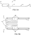
- Figure 5B is a plan view showing mating surfaces of parts 9A, 9B, wherein each includes a channel 91 configured to receive handle portion 105 and tunneling member first end 121 of tool 100.
- Channels 91 act as an attachment feature that secures parts 9A, 9B to tool 100 when mating features 93A, 93B of the opposing surfaces are brought together in confronting engagement for a snap fit around tool 100.
- parts 9A, 9B may include any other suitable type of attachment feature to secure tool 100 thereto, as well as any suitable type of mating features to secure parts 9A, 9B together around tool 100.
- Parts 9A, 9B may be formed, for example, by injection molding, from a relatively hard medical grade polymer.
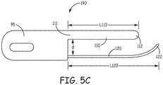
- Figure 5C is a plan view of tool 100 having thus been converted with parts 9A, 9B to a tool 190, wherein tool 190 includes a relatively straight guide member 110 extending from a first end 111 thereof to a second end 112 thereof, alongside tunneling member 120. Second end 112 of guide member 110 may in some instances have a curvature such that it should ride on the skin over the sternum without binding on the skin. For example, second end 112 may be rounded enough to easily slide over the skin without poking.
- Figure 5C illustrates a handle 95 of tool 190, which is formed by the portions of parts 9A, 9B surrounding handle portion 105 of tool 100.
- handle 95 has a looped gripping portion, for example, to receive fingers of a hand of an operator, but may have any other suitable configuration for gripping, such as is described for alternate tool embodiments herein, or known in the art.
- handle 95 is coupled to first end 111 of guide member 110 and to first end 121 of tunneling member 120, rather than being coupled only to guide member 110.
- the operator may orient tunneling member 120 in a similar fashion to that shown for tool 40 in Figure 4B to insert blunt tip 122 of tunneling member 120 through incision site IS.
- an implant system includes tool 190 and an introducer sheath, for example, similar to any of the embodiments of introducer sheath 70 described above. The sheath may be placed over tunneling member 120 either before or after accessing and tunneling through the sub-sternal space.
- Figures 6A-C are a plan view, a corresponding end view, and top view of a tool 50, according to some additional embodiments.
- Figures 6A-C illustrate tool 50 including a relatively straight guide member 51 and a tunneling member 52 that extend in the same direction from first ends 511, 521 thereof, alongside and coplanar with one another.
- a handle 55 of tool 50 is shown being coupled to first ends 511, 521 of guide and tunneling members 51, 52, and extending at an angle ⁇ with respect to the relatively straight extent of guide member 51, wherein angle ⁇ may be between approximately 150 degrees and 160 degrees, and is coplanar with guide and tunneling members 51, 52.
- Figures 6A-C further illustrate a length L52 of tunneling member 52, from first end 521 to a blunt tip 522 thereof, being greater than a length L51 of guide member 51, from first end 511 to a second end 512 thereof, but, with reference to Figure 6D , by no more than the above-described depth D of insertion so that guide member second end 512 will abut location E adjacent incision site IS when tip 522 reaches depth D.
- guide member length L51 may be approximately 6 inches (15.2 cm)
- tunneling member length L52 may be approximately 7 inches (17.8 cm).
- tunneling member length L52 may be approximately equal to, or less than guide member length L51.
- tunneling member 52 is formed from a medical grade metal rod, such as a series 300 stainless steel rod having a diameter in a range from approximately 0.1 inch (2.5 mm) to approximately 0.14 inch (3.5 mm), for example, approximately 0.122 inch (3 mm); and handle 55 and guide member 51 are each formed from a relatively hard medical grade polymer.
- tunneling member 52 may also be formed from a relatively hard medical grade polymer.
- Guide member 51 may have a diameter in a range from approximately 0.35 inch (9 mm) to approximately 0.4 inch (10 mm), for example, approximately 0.374 inch (9.5 mm).
- Handle 55 may be insert molded around first ends 511, 521 of guide and tunneling members 51, 52, or handle 55 and guide member 51 may be integrally formed, for example, by insert molding around first end 521 of tunneling member 52, or handle 55, guide member 51, and tunneling member 52 may each be separately formed and then assembled together.
- handle 55 has a bulbous contour, for example, with a maximum diameter DH in a range from approximately 1.5 inches to approximately 2.5 inches, for example, approximately 2 inches (51 mm), and length LH in a range from approximately 3 inches to approximately 3.5 inches, for example, approximately 3.25 inches (82.6 mm).
- the contour and angle ⁇ of handle 55 may provide for ergonomic handling of tool 50 that increases an ease of use for the operator, yet other contours and orientations of handle 55 are not outside the scope of the present invention.
- Figure 6D illustrates tool 50 oriented such that blunt tip 522 of tunneling member 52 is adjacent incision site IS, and guide and tunneling members 51, 52 are approximately orthogonal with respect to the superior extent of sternum 13 from xiphoid process 20.
- the operator may rotate guide member 51 and tunneling member 52 together in the inferior direction, per arrow INF, before advancing tunneling member 52 in the superior direction, per arrow SUP, as is shown in Figure 6E .
- tunneling member 52 has an elastic property and a pre-formed curvature that bias blunt tip 522 toward second end 512 of guide member 51.
- Figure 6A shows a gap g between blunt tip 522 and second end 512 of guide member 51, which may be in a range from approximately 0.2 inch to approximately 0.3 inch, for example, approximately 0.25 inch (6.4 mm), according to some embodiments, when tunneling member 52 is in the relaxed state (e.g. biased toward guide member 51 by the elastic property thereof). Gap g may be increased, for example, per arrow S of Figure 6D , when the operator inserts and begins to rotate tool 50 in the inferior direction, per arrow INF, to advance tunneling member 52 beneath sternum 13 in the superior direction, per arrow SUP.
- the bias of tunneling member 51 which seeks to restore gap g, causes blunt tip 522 to 'ride' adjacent the inside surface of sternum 13 during the superior advancement thereof.
- FIGS 6A and 6C also show guide member 51 divided into first and second sections 51A, 51B, which may be joined together by a hinge member 515.
- Hinge member 515 allows guide member second section 51B to rotate per arrow H, for example, providing additional clearance as the operator inserts and advances tunneling member 52.
- Hinge member 515 may be constructed in any suitable manner known to those skilled in the art.
- Some embodiments of hinge member 515 include a torsion spring, while others include a coiled spring member extending around a junction between first and second sections 51A, 51B.
- guide member 51 is not divided into sections 51A, 51B.
- the superior advancement of tunneling member 52 beneath sternum 13 may be stopped by the joined first ends 511, 521 of guide and tunneling members 51, 52 abutting incision site IS.
- a distance d between guide member 51 and tunneling member 52, in proximity to first ends 511, 521 thereof, is not sufficient for a size of a given patient (e.g., approximately equal to depth D of the patient)
- the operator may not be able to advance tunneling member 52 enough to create a sub-sternal tunnel of sufficient length to accommodate the medical device.
- tool 50 may include an adjustment mechanism to vary distance d.
- Figure 6A illustrates one type of adjustment mechanism that is formed by a threaded interface T that couples first end 521 of tunneling member 52 to handle 55.
- handle 55 may be rotated relative to guide member 51, to adjust distance d, per arrow A, thereby moving tunneling member 52 into multiple positions relative to guide member 51.
- handle 55 may incorporate any other suitable type of adjustment mechanism.
- a kit that includes an assortment of interchangeable tunneling members 52 having shanks S5 of different lengths.
- a kit may include an assortment of mating parts 9A, 9B of different sizes to vary distance d of tool 190 assembled from tool 100.
- tunneling member 52 may be radiopaque and guide member 51 may include a radiopaque marker 502 located in proximity to second end 512.
- Figures 6A-C further illustrate guide member 51 including an optional orientation feature 514, which has a fin-like configuration and is joined to second end 512 and extends away from, and coplanar with guide member 51 and tunneling member 52.
- feature 514 for any tilting, for example, per arrows t, as an indicator that tunneling member 52 has been inadvertently rotated so that curved tip 522 is directed away from the superior direction of the advancement of tunneling member 52. It should be noted that feature 514, in alternate embodiments, may be located in other positions along guide member 51, and/or take on other suitable configurations.
- Figure 7A is a plan view of a tool 80, according to some alternate embodiments.
- Figure 7A illustrates tool 80 including a relatively straight guide member 81 and a tunneling member 82 that extend in the same direction from first ends 811, 821 thereof, alongside and coplanar with one another.
- a length of tunneling member 82, from first end 821 to a blunt tip 822 thereof, is shown being approximately equal to a length of guide member from first end 811 to a second end 812 thereof.
- guide member 81 may be formed from a medical grade polymer, and may include an optional orientation fin 814.
- Figure 7A further illustrates a handle 85 of tool 80 being coupled to first ends 811, 821 of guide and tunneling members 81, 82.
- Handle 85 includes first and second finger recesses 853, 854, which are shown located in proximity to guide and tunneling member first ends 811, 821, and an adjustment mechanism 87, which is shown located in proximity to recesses 853, 854. Adjustment mechanism 87 is shown coupling first end 821 of tunneling member 82 to handle 85, wherein a first part 871 of mechanism 87 may be a column of protrusions or recesses configured to interlock with a second part 872 of mechanism 87, for example, a tab member secured to first end 821 of tunneling member 82.
- an operator may move second part 872 of adjustment mechanism 87 over first part 871, per arrow A, to lock tunneling member 82 at different positions relative to guide member 81, and thereby vary a distance d8 between guide member 81 and tunneling member 82, according to different sizes of patients (e.g., different depths D, as described above in conjunction with Figure 6E ).
- distance d8 may be varied by about 0.5 inch (12.7 mm), wherein a maximum distance d8 may be approximately 2.24 inch (57 mm).
- handle 85 may extend at an angle with respect to the relatively straight extent of guide member 81, which provides some clearance for an operator's hand while handling and manipulating tool 80, for example, as shown in the schematics of Figures 7B-C .
- Figure 7B shows the operator's hand gripping handle 85 such that a forefinger of the hand rests in first finger recess 853 of handle 85, and a thumb of the hand rests in second finger recess 854 of handle 85.
- the grip of Figure 7B may be one suitable for steering blunt tip 822 of tunneling member 82 into incision site IS as shown.
- Figure 7C shows the operator's hand gripping handle 85 such that the thumb extends alongside first recess 853 and the forefinger wraps around handle 85 alongside second recess 854.
- the grip of Figure 7C may one suitable for advancing the inserted tunneling member 82 in the superior direction to create a sub-sternal tunnel.
- handle 85 may be formed by a relatively hard plastic or metal body 852 over-molded with a relatively softer elastomer 851, to enhance gripping, and each recess 853, 854 may have a row of elastomer gripping nubs over-molded thereon.
- guide member 81 may be divided into first and second sections 81A, 81B, which may be joined together by a hinge member 815, for example, to provide additional clearance as the operator inserts and advances tunneling member 82, by allowing guide member second section 81B to rotate as shown in Figure 7C and by the dashed lines in Figure 7A .
- Hinge member 815 may be constructed in any suitable manner known to those skilled in the art. Some embodiments of hinge member 815 include a torsion spring, while others include a coiled spring member extending around a junction between first and second sections 81A, 81B.
- Figure 8A is a plan view of a tool 60, according to some embodiments; and Figure 8B is an enlarged detail of a portion of tool 60.
- Figure 8A illustrates tool 60 including a relatively straight guide member 61 and a tunneling member 62, wherein guide member 61 extends over a length from a first end 611 thereof to a second end 612 thereof, and tunneling member 62 extends over a length from a first end 621 thereof to a blunt tip 622 thereof.
- Members 61, 62 extend in the same direction from first ends 611, 621 thereof, alongside and coplanar with one another, and may have lengths and diameters similar to those of the corresponding members 51, 52 of tool 50.
- tunneling member length L62 may be approximately equal to, or less than guide member length L61.
- Guide member 61 may be formed from a medical grade polymer, and is shown including an optional orientation fin 614, for example, like guide members 51, 81 of tools 50, 80.
- Dashed lines in Figure 8A represent an optional metal rod embedded in guide member 61, for example, to lend stiffness and/or radiopacity.
- Figure 8A further illustrates a handle 65 of tool 50 coupled to first ends 611, 621 of guide and tunneling members 61, 62, wherein handle 65 may be formed form a relatively hard medical grade plastic, in some cases integrally formed with guide member 61.
- Handle 65 preferably has an oval cross-section (into the page), and is shown including an optional plurality of finger recesses 653 to conform to a hand of the operator. Dotted lines illustrate an alternate handle embodiment in which handle 65 is angled relative to the extent of guide member 61, for example, like handle 85 of tool 80, to provide some clearance for an operator's hand when handling tool 60 during the tunneling procedure.
- tool 60 further includes a spring-loaded coupling 625 between handle 65 and tunneling member first end 621, which is shrouded within a bulk of handle 65.
- Figure 8B illustrates coupling 625 including a spring mechanism 656 and a pivot member 658, wherein spring mechanism 656 is biased in a direction SB1 such that tunneling member 62, rotating around pivot member 658, is biased toward guide member 61, per arrow SB2.
- guide member second end 612 of tool 60 may abut location E adjacent incision site IS when an operator has inserted blunt tip 622 to depth D, and, as the operator begins to rotate the inserted tool 60 in the inferior direction, per arrow INF, to advance tunneling member 62 beneath sternum 13 in the superior direction, per arrow SUP, the operator may apply enough force against the spring bias of spring mechanism 656 to allow tunneling member 62 to spread apart from guide member 61, per arrow S ( Figure 8A ), but the spring bias of tool 60 can still be sufficient to keep blunt tip 622 riding along the inner surface of sternum 13 during the superior advancement thereof.
- tunneling member 62 is radiopaque
- guide member 61 includes a radiopaque member, for example, the rod described above (dashed lines in Figure 8A )
- the operator may employ fluoroscopy to monitor the relative locations of tunneling and guide members 62, 61, while advancing blunt tip 622 beneath sternum 13.
- the joined first and second ends 611, 621 of guide and tunneling members 61, 62 can serve to stop the superior advancement of blunt tip.
- Figures 8C-D are plan views of a variation of tool 60.
- Figures 8C-D illustrate a tool 600 including a relatively straight guide member 601 and a tunneling member 602 that extend alongside and coplanar with one another. Similar to guide and tunneling members 61, 62 of tool 60, guide member 601 extends from a first end 6011 thereof to a second end 6012 thereof, and tunneling member 602 extends from a first end 6021 thereof to a blunt tip 6022 thereof, both in the same direction.
- Figures 8C-D further illustrate a handle 605 of tool 600 coupled to first ends 6011, 6021 of guide and tunneling members 601, 602, wherein handle 605 includes an adjustment mechanism 607 that allows an operator to vary a distance d6 between guide member 601 and tunneling member 602, according to different sizes of patients (e.g., different depths D, as described above in conjunction with Figure 6E ).
- adjustment mechanism 607 includes a slot (shown with a dotted line) formed in handle 605 to receive a shank S6 of guide member 601, and a set screw 6076 for securing shank S6 in one of a plurality of positions, via one of a plurality of mating apertures 6016 formed in shank S6.
- Figure 8C shows set screw 6076 securing shank S6 (shown with dashed lines) to hold guide member 601 in a first position relative to tunneling member 602; and Figure 8D shows set screw 6076 securing shank S6 to hold guide member 601 in a second position relative to tunneling member 602, at which distance d6 is greater than when held at the first position.
- Handle 605 may incorporate any other suitable type of adjustment mechanism, according to some alternate embodiments.
- guide member 601 of tool 600 is shown divided into first and second sections 601A, 601B that are joined together by a hinge member 6015, for example, to provide additional clearance as the operator inserts and advances tunneling member 602, by allowing guide member second section 601B to rotate per arrow H6 ( Figure 8C ).
- Hinge member 6015 may be constructed in any suitable manner known to those skilled in the art, and/or described herein, and is shown including a coiled spring member extending thereabout to provide a spring-bias thereto.
- any or all of the above-described tools 50, 80, 60, 600 may be incorporated in a system that also includes an introducer sheath, for example, sheath 70 described above.
- the sheath is mounted on tunneling member 52, 82, 62, 602, prior to the insertion of blunt tip 522, 822, 622, 6022, and advanced along with tunneling member 52, 82, 62, 602 as it creates the sub-sternal tunnel.
- Figures 9A-B are plan views of a tool 90, according to some additional embodiments.
- Figures 9A-B illustrate tool 90 including a relatively straight guide member 91 and a tunneling member 92 that extend alongside and coplanar with one another, wherein guide member 91 extends from a first end 911 thereof to a second end 912 thereof, and tunneling member 92 extends from a first end 921 thereof to a blunt tip 922 thereof, both in the same direction.
- Tunneling member 92 is shown including a first section 92A that extends approximately parallel to guide member 91 and a second section 92B that has a pre-formed curvature biasing blunt tip 922 generally toward guide member 91.
- First section 92A being a major portion of the tunneling member 92, allows the operator to use guide member 91 as an external visual cue of the angle at which tunneling member 92 extends during the insertion thereof and tunneling therewith, while the curvature of tunneling member second section 92 can cause blunt tip 922 to 'ride' adjacent the inside surface of sternum 13 during the superior advancement thereof when tunneling.
- Figures 9A-B further illustrate a handle 950 of tool 90 being coupled to first ends 911, 921 of guide and tunneling members 91, 92, and including a looped gripping portion to accommodate various operator hand sizes, with finger recesses 953 formed therein.
- handle 950 also includes an adjustment mechanism 97 that allows an operator to vary a distance d9 between guide member 91 and tunneling member 92, in proximity to first ends 911, 921 thereof, for example, by sliding guide member 91 relative to tunneling member 92 along a yoke 951 of handle 950.
- Figure 9A shows guide member 91 held at a first position relative to tunneling member 92
- Figure 9B shows guide member 91 held at a second position relative to tunneling member 92, wherein distance d9 at the second position is less than that at the first position.
- Figure 9C is an enlarged detail view inside handle yoke 951 that illustrates adjustment mechanism 97 being formed by a shank S9 of guide member 91 mounted in sliding engagement within a slot 971 of yoke 951.
- a flat, or leaf spring member (shown with dashed lines) may be mounted to a face of shank S9 and interface with a confronting face of slot 971 to hold guide member 91 in place by preventing guide member 91 from freely sliding within slot 971, while allowing the operator to forcibly slide guide member 91 to various positions.
- shank S9 and yoke 951 that prevent the free sliding of guiding member 91 may be employed, for example, ratchet teeth or any other interlocking/detent-type interface.
- any other suitable coupling between guide member 91 and handle 950 which allows adjustment of distance d9, while maintaining the parallel orientation of guide member 91 relative to tunneling member first section 92A, is not outside the scope of the present disclosure.
- tool 90 also includes an extension tip 93 joined to second end 912 of guide member 91, wherein extension tip 93 is moveable from a retracted position (shown with dotted lines in Figure 9A ) alongside guide member 91 and between the first and second ends 911, 912 thereof, to an extended position, extending away from guide member second end 912.
- a pivot joint couples extension tip 93 to second end 912 of guide member 91, while, in alternate embodiments, extension tip 93 is coupled to guide member 91 in a telescoping arrangement.
- a free end 932 of extension tip 93 is approximately aligned with blunt tip 922 of tunneling member 92, for example, to help the operator understand the sub-sternal location of tip 922 while creating the sub-sternal tunnel.
- Figures 9A-B further illustrate tool 90 including an optional bubble level 914 that can help the operator monitor an orientation of tool with respect to the horizontal during the tunneling procedure.
- handle 950 of tool 90 includes an attachment feature configured to reversibly secure handle 950 to first end 921 of tunneling member 92 so that tunneling member 92 extends alongside and coplanar with guide member 91, as shown in Figures 9A-B .
- the attachment feature allows detachment of tunneling member 92 from handle 950, for example, to allow passage of the introducer sheath over tunneling member 92 and into the sub-sternal tunnel, so that the sheath does not need to be pre-loaded around member 92, in contrast to some instances described above for some other tool embodiments.
- Figures 9A-B illustrate a lever 952 of the attachment feature, which, when lifted, or rotated, per arrow R, allows the operator to slide tunneling member 92 out from a channel of handle 950.
- the attachment feature of handle 950 further includes a block 955 mounted within handle 950 and coupled to lever 952 via a dowel 956, wherein block 955 defines a portion 905 of the channel through which tunneling member 92 extends.
- Channel portion 905 when offset from, or misaligned with, a remainder of the channel, locks tunneling member 92 to handle 950, but, when lever 952 is rotated per arrow R, block 955 is moved to align channel portion 905 and thereby release tunneling member 92 from handle 950.
- Lever 952 may be formed from polycarbonate, and block 955 from stainless steel, PEI UltemTM or PEEK.
- a kit includes a plurality of handles having the above-described attachment feature for tunneling member 92 but not having the above described adjustment mechanism 97. Rather, each of the handles in the kit has a yoke, similar to yoke 951, for example, to which first end 911 of guide member 91 is attached, of a different size. Thus distance d9 is varied according to the size of the yoke of the handle selected from the kit for attachment to tunneling member 92.
- Figures 10A-B are plan views of another type of tool 900, according to some embodiments.
- Figures 10A-B illustrate tool 900 including a relatively straight guide member 901 and a tunneling member 902 that extend alongside and coplanar with one another, wherein guide member 901 extends from a first end 9011 thereof to a second end 9012 thereof, and tunneling member 902 extends from a first end 9021 thereof to a blunt tip 9022 thereof, both in the same direction.
- Tool 900 is also shown including a handle 905 coupled to first ends 9011, 9021 of guide and tunneling members 901, 902, and including a looped gripping portion with finger recesses 953 formed therein, like handle 95 of tool 90.
- Handle 905 of tool 900 may include the attachment feature described above for tool 90, which is configured to reversibly secure handle 905 to first end 9021 of tunneling member 902, and includes lever 952 operable to alternately release and secure tunneling member first end 9021.
- Figures 10A-B further illustrate tool 900 including an extension tip 903 joined to second end 9012 of guide member 901 by a pivot joint, wherein extension tip 903 is moveable, per arrow F, from a retracted position ( Figure 10A ) alongside guide member 901 and between the first and second ends 9011, 9012 thereof, to an extended position ( Figure 10B ) extending away from guide member second end 9012 and toward blunt tip 9022 of tunneling member 902.
- Figure 6D if the operator initially orients tool 900 in a similar fashion to that illustrated for tool 50, while inserting blunt tip 9022 of tunneling member 902 through incision site IS, the operator will likely have extension tip 903 in the retracted position until gaining sub-sternal access.
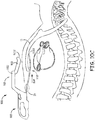
- extension tip 903 after gaining sub-sternal access, the operator may move tip 903 to the extended position at which a free end 9032 of tip 903 'rides' adjacent to the patient's epidermis as the operator advances tunneling member 902 in the superior direction, per arrow SUP, to create a sub-sternal tunnel.
- extension tip 903, once moved toward the extended position is free to move under its own weight toward tunneling member 902, thus, with reference back to Figure 10B , an angle ⁇ at which the extended extension tip 903 extends relative to guide member 901 is free to change according to the size of the patient.
- free end 9032 of extension tip 903 approximately indicates a location of the underlying blunt tip 922 of tunneling member 92, as a reference for the operator.
Landscapes
- Health & Medical Sciences (AREA)
- Life Sciences & Earth Sciences (AREA)
- Heart & Thoracic Surgery (AREA)
- Surgery (AREA)
- Biomedical Technology (AREA)
- Nuclear Medicine, Radiotherapy & Molecular Imaging (AREA)
- Animal Behavior & Ethology (AREA)
- General Health & Medical Sciences (AREA)
- Public Health (AREA)
- Veterinary Medicine (AREA)
- Engineering & Computer Science (AREA)
- Medical Informatics (AREA)
- Molecular Biology (AREA)
- Cardiology (AREA)
- Radiology & Medical Imaging (AREA)
- Pathology (AREA)
- Vascular Medicine (AREA)
- Gastroenterology & Hepatology (AREA)
- Prostheses (AREA)
- Surgical Instruments (AREA)
- Orthopedic Medicine & Surgery (AREA)
Description
- The present disclosure pertains to tools and associated methods for safely gaining access to extravascular spaces, and more particularly to those suited to safely gain access into a sub-sternal space for the positioning of a medical device therein.
- Implantable medical electrical leads, included in systems that are known in the art for delivering cardiac therapy and/or for providing cardiac monitoring, are often implanted transvenously within a heart of a patient. But extravascular implant sites may be preferred, for example, in those patients where vascular access is difficult, or because transvenous leads can become fibrosed in the heart over time, which makes lead revision and extraction procedures challenging.
US 2014/330208 A1 relates to systems and methods for implanting a medical electrical lead. - The present invention is defined by the appended claims.
- Aspects, embodiments or examples of the present disclosure which do not fall within the scope of the appended claims do not form part of the present invention.
- This disclosure provides tools and implant techniques utilizing such tools to gain access and implant a lead within extravascular spaces. In one example, this disclosure provides a tool for creating a sub-sternal tunnel in a patient. The tool comprises a relatively straight guide member extending from a first end thereof to a second end thereof, a tunneling member extending from a first end thereof to a tip thereof, the tunneling member extending alongside and coplanar with the guide member, the first end of the tunneling member and the first end of the guide member being joined together, and a handle coupled to the guide member.
- In another example, handle for a tunneling tool comprises a guide member extending from a first end to a second end, an attachment feature configured to reversibly secure the handle to a first end of a tunneling member so that the secured tunneling member extends alongside and coplanar with the guide member, and a gripping portion located in proximity to the attachment feature and the first end of the guide member.
- This summary is intended to provide an overview of the subject matter described in this disclosure. It is not intended to provide an exclusive or exhaustive explanation of the apparatus and methods described in detail within the accompanying drawings and description below. Further details of one or more examples are set forth in the accompanying drawings and the description below.
- The following drawings are illustrative of particular exemplary embodiments and do not limit the scope of the invention. The drawings are not to scale (unless so stated) and are intended for use in conjunction with the explanations in the following detailed description. Embodiments will hereinafter be described in conjunction with the appended drawings wherein like numerals denote like elements.
-
Figures 1A-B are schematics showing an exemplary extravascular implant. -
Figure 2 is a schematic for describing sub-sternal access. -
Figure 3A is a plan view of an example tool for tunneling within a patient. -
Figure 3B is a schematic depicting the tool ofFigure 3A positioned for insertion into a body of a patient. -
Figure 3C is a schematic depicting the tool ofFigure 3A , according to some embodiments and methods, advanced superiorly beneath a sternum of the patient. -
Figure 4A is a plan view of another example tool for tunneling within a patient. -
Figure 4B is a schematic depicting the tool ofFigure 4A positioned for insertion into the body of the patient. -
Figure 4C is a schematic depicting the tool ofFigure 4A , according to some embodiments and methods, advanced superiorly beneath a sternum of the patient. -
Figure 5A is a plan view of an exemplary tunneling tool that may be known to those skilled in the art. -
Figure 5B is a plan view of mating parts of a handle for the tunneling tool ofFigure 5A , according to some embodiments. -
Figure 5C is a plan view of the parts ofFigure 5B joined to the tool ofFigure 5A , according to some embodiments. -
Figures 6A-C are a plan view, a corresponding end view, and a top view of another type of tool, according to some additional embodiments. -
Figure 6D is a schematic depicting the tool ofFigures 6A-C positioned for insertion into the body of the patient. -
Figure 6E is a schematic depicting the tool ofFigures 6A-C , according to some embodiments and methods, advanced superiorly beneath a sternum of the patient. -
Figure 7A is a plan view of a tool, according to some alternate embodiments. -
Figures 7B-C are schematics depicting handling the tool ofFigure 7A , according to some methods. -
Figure 8A is a plan view of yet another type of tool, according to some embodiments. -
Figure 8B is an enlarged detail of a portion of the tool ofFigure 8A . -
Figures 8C-D are plan views of a variation of the tool shown inFigures 8A-B . -
Figures 9A-B are plan views of a tool, according to some additional embodiments. -
Figure 9C is an enlarged detail view of a portion of the tool shown inFigures 9A-B . -
Figures 10A-B are plan views of another type of tool, according to some embodiments. -
Figure 10C is a schematic depicting the tool ofFigures 10A-B , according to some embodiments and methods, advanced superiorly beneath a sternum of the patient. - The following detailed description is exemplary in nature and is not intended to limit, in any way, the scope, applicability, or configuration of the tools and techniques described in this disclosure. Rather, the following description provides practical examples, and those skilled in the art will recognize that some of the examples may have suitable alternatives.
-
Figures 1A-B are schematics showing an exemplary extravascular implant of anexemplary system 10 that includes apulse generator 14 and an implantable medicalelectrical lead 16 coupled thereto.Pulse generator 14 is shown implanted subcutaneously on the left mid-axillary of apatient 12, superficially of the patient's ribcage.Pulse generator 14, which may be configured to provide cardiac pacing and/or defibrillation therapy, includes a hermetically sealed housing in which the appropriate electronics and a power supply are contained, and which is formed from a conductive material, such as titanium, or from a combination of conductive and non-conductive materials.Pulse generator 14 further includes a connector module by whichlead 16 is electrically coupled to the electronics contained therein, for example, by electrical contacts contained within the connector module and a corresponding hermetically sealed feedthrough assembly, such as is known in the art. The conductive material of device housing may be employed as an electrode, for example, to provide the aforementioned therapy in conjunction with one or more pace/sense electrodes 22, 26 and/or a defibrillation electrode 24 oflead 16, which is shown implanted in asub-sternal space 3, for example, within the loose connective tissue and/or sub-sternal musculature of the anterior mediastinum.Lead 16 may have any of a number of configurations. For example,lead 16 may include more or fewer pace/sense electrodes. In another example,lead 16 may include more than one defibrillation electrode 24 and/or have a defibrillation electrode that is formed of multiple segments. Examples of leads with multiple defibrillation electrodes and/or segments are described in commonly assigned, co-pendingU.S. Patent Publication No. 2015/0306375 (Marshall et al. ),U.S. Patent Publication No. 2015/0306410 (Marshall et al. ) andU.S. Patent Publication No. 2016/0158567 (Marshall et al. ). With reference toFigure 1B , thesub-sternal space 3 may be viewed as being bounded laterally bypleurae 39 that enclose the patient's lungs, posteriorly by thepericardial sac 15 that encloses the patient'sheart 6, and anteriorly by thesternum 13. In some instances, the anterior wall of the anterior mediastinum may also be formed by the transversus thoracis and one or more costal cartilages. AlthoughFIG. 1A and1B are described in the context of the distal portion oflead 16 being placed within thesub-sternal space 3, in other embodiments, the tools and implant techniques described herein may be used to implant a distal portion of thelead 16 at other locations outside the heart. In one example, the tools may be used to place the distal portion oflead 16 intra-pericardially via a percutaneous subxiphoid approach. -
Figure 2 is a schematic showing an access site A for making a passageway between a patient'sdiaphragm 19 andxiphoid process 20 ofsternum 13, for example, to create a sub-sternal tunnel in which to position a medical device, such as medicalelectrical lead 16. After making a superficial incision, an operator, using tools and techniques known to those skilled in the art, may open a passageway betweendiaphragmatic attachments 18 anddiaphragm 19, for example, by blunt dissection, in which the operator may employ a tunneling tool, for example, the Medtronic® Model 6996T, to both create the passageway and then form a sub-sternal tunnel (e.g. along the dotted line ofFigure 2 ). However, because the bony structure of the sternum inhibits external palpation, the operator must take extra care, during the blunt dissection and/or tunneling, not to injure sub-sternal structures or the chest cavity, which could compromise thepleura 39 of the lungs or theheart 6. Thus, as indicated above, tools and associated methods disclosed herein are configured to help an operator gain the desired sub-sternal access and create a space in which to position a medical device, such as medicalelectrical lead 16, in a more controlled fashion that mitigates the risk of injuring bodily organs. -
Figure 3A is a plan view of atool 30 for gaining sub-sternal access and creating a sub-sternal tunnel in a patient, according to some embodiments.Figure 3A illustratestool 30 including a relativelystraight guide member 31 and a tunnelingmember 32, which are joined together at first ends 311, 321 thereof.Guide member 31 is shown extending over a length L31, fromfirst end 311 to asecond end thereof 312. Tunnelingmember 32 is shown extending, in the same direction, over a length L32, fromfirst end 321 to ablunt tip 322 thereof.Tool 30 also includes ahandle 35, which is shown coupled tosecond end 312 ofguide member 31. According to the illustrated embodiment, handle 35,guide member 31, and tunnelingmember 32 are all formed from asingle rod 39, for example, a relatively rigid medical grade polymer rod or a medical grade metal rod. In one example,rod 39 may be formed of 300 series stainless steel having a circular cross-section, which may have a diameter in the range from approximately 0.1 inch (2.5 mm) to approximately 0.14 inch (3.5 mm), for example, approximately 0.12 inch (3.1 mm). According to some embodiments,blunt tip 322 of tunnelingmember 32 andsecond end 312 ofguide member 31 are biased toward one another, as indicated by arrows B, for example, by an elasticity ofrod 39. In other examples,tool 30 may be formed from multiple components, whereinguide member 31 may be biased toward tunnelingmember 32, and/or tunnelingmember 32 may be biased towardguide member 31. Furthermore, one or both ofguide member 31 and tunnelingmember 32 may have a non-circular cross-section, in some alternate embodiments. - In the example of
Figure 3A , length L32 of tunnelingmember 32 is less than length L31 ofguide member 31. According to the illustrated embodiment, the difference in lengths L31, L32 ofguide member 31 and tunnelingmember 32 is useful to control an angle of entry through an incision site IS of a patient, for example, as illustrated inFigure 3B . Controlling the angle of entry can mitigate the risk of penetrating too far posterior and injuring sub-sternal structures or the chest cavity.Figure 3B is a schematic depictingtool 30 positioned for insertion through incision site IS and into a body of a patient. Incision site IS is located in proximity toxiphoid process 20 ofsternum 13, for the above-described access tosubsternal space 3, betweendiaphragmatic attachments 18 and diaphragm 19 (Figure 2 ). -
Figure 3B illustratesguide member 31 and tunnelingmember 32 oftool 30 oriented at an obtuse angle θ relative to a superior extent ofsternum 13 from incision site IS, so that guide membersecond end 312 will abut a location E, for example, an epidermal location, as the operator insertsblunt tip 322 of tunnelingmember 32 through incision site IS. With further reference toFigure 3B , the configuration oftool 30 forces the operator to rotate tunnelingmember 32 and guidemember 31 in an inferior direction, per arrow INF, in order to insert tunneling memberblunt tip 322 through incision site IS, thereby keeping the operator from pushingblunt tip 322 too deep or in a wrong direction. According to an alternative exemplary embodiment, tunneling member length L32 may be approximately equal to guide member length L31, in which case, the operator need not orienttool 30 at obtuse angle θ forsecond end 312 to abut location E, but rather approximately orthogonal to the superior extent ofsternum 13 fromxiphoid process 20, prior to rotatingtool 30 in the inferior direction to insertblunt tip 322 through incision site IS. - Furthermore,
Figure 3C shows the extent ofguide member 31 aligned alongsternum 13, outside the patient's body, to help the operator in advancingtunneling member 32, oncetip 322 is inserted, in a proper superior direction, per arrow SUP, and thereby creating the sub-sternal tunnel. According to some embodiments, the bias ofblunt tip 322 towardguide member 31 can causeblunt tip 322 to 'ride' adjacent an inside surface ofsternum 13 during the superior advancement thereof as an additional aid to the operator. Likewise,second end 312 ofguide member 31 may in some instances be rounded such that it easily slides over the skin without poking while traversing in the superior direction. With further reference toFigure 3C , superior advancement of tunnelingmember 32 beneathsternum 13 may be stopped when the joined first ends 311, 321 of guide andtunneling members Figure 3A ,tool 30 may include an optional marker at alocation 302 onguide member 31 that is approximately aligned withblunt tip 322 of tunnelingmember 32 to provide an indicator that the operator may reference relative to external landmarks of the patient's body to determine the position oftip 322 beneathsternum 13 and thus stop superior advancement at a desired sub-sternal location. However, according to some embodiments and methods,tunneling member 32 and either all or just the marker ofguide member 31 are radiopaque, and the operator uses fluoroscopy to monitor the relative locations of tunneling and guidemembers blunt tip 322 beneathsternum 13. -
Figure 3C showstool 30 as part of asystem 370 that also includes anintroducer sheath 70, according to some embodiments, whereinsheath 70 includes a lumen (not shown). The lumen ofsheath 70 includes a proximal opening located at aproximal end 71 ofsheath 70, and a distal opening located at adistal end 72 of sheath, and is sized to receive passage of a medical device therethrough, for example, lead 16 (Figures 1A-B ).Figure 3C illustratesintroducer sheath 70 mounted ontool guide member 31, for example, having been mounted prior to insertion and advancement of tunnelingmember 32. According to the illustrated embodiment,sheath 70 is configured to slideably engage withguide member 31 and tunnelingmember 32, and has a flexibility to track around the bend oftool 30 that joins first ends 311, 321 of the guide andtunneling members member 32, as shown, to create the sub-sternal tunnel, the operator can slidesheath 70 through incision site IS and along tunnelingmember 32 into the tunnel, while leaving sheathproximal end 71 external at incision site IS. Then, for example, aftertool 30 is withdrawn from the patient's body, leavingsheath 70 within the sub-sternal tunnel, the operator may pass a medical device, such as the above describedlead 16, through the sheath lumen, via the proximal opening thereof at sheathproximal end 71. The operator then removessheath 70 from the body, leavinglead 16 within the sub-sternal tunnel, for example, by slitting or splittingsheath 70 from around lead, according to some embodiments and methods. - In alternative system embodiments,
sheath 70 may include an open channel that extends alongside the lumen thereof and that allows forsheath 70 to slideably engage with tunnelingmember 32, from tunneling memberfirst end 321 in proximity to incision site IS, after tunnelingmember 32 has created the sub-sternal tunnel. An example of an open channel sheath is described in detail in commonly assigned United States Patent Application No.2015/0133953 . Such a sheath need not be passed around the bend oftool 30, fromguide member 31 to tunnelingmember 32. Alternately,sheath 70 may be mounted on tunnelingmember 32 prior to the insertion oftunneling member tip 322 through incision site IS such thatsheath 70 is maneuvered and advanced along with tunnelingmember 32 as the sub-sternal tunnel is created. Furthermore, according to some alternate methods,sheath 70 may be inserted into the sub-sternal tunnel aftertool 30 is removed from the patient's body, or the medical device may be inserted into the tunnel without need for any sheath. -
Figure 4A is a plan view of atool 40, according to an alternate embodiment.Figure 4A illustratestool 40, liketool 30, including a relativelystraight guide member 41 and a tunnelingmember 42, which are joined together at first ends 411, 421 thereof, and wherein guide andtunneling members tool 30, tunnelingmember 42 includes ablunt tip 422, ahandle 45 joined to asecond end 412 ofguide member 41, and handle 45,guide member 41, and tunnelingmember 42 are all formed from asingle rod 49.Rod 49 may, for example, be a medical grade stainless steel rod likerod 39 oftool 30, described above. According to some embodiments,blunt tip 422 of tunnelingmember 42 andsecond end 412 ofguide member 41 are biased toward one another, as indicated by arrows B, for example, by an elasticity ofrod 49. In other examples,tool 40 may be formed from multiple components, whereinguide member 41 may be biased toward tunnelingmember 42, and/or tunnelingmember 42 may be biased towardguide member 41. Furthermore, one or both ofguide member 41 and tunnelingmember 42 may have a non-circular cross-section in some alternate embodiments. - With further reference to
Figure 4A ,tool 40 differs fromtool 30 in that a length L42 of tunnelingmember 42, fromfirst end 421 to tip 422, is greater than a length L41 ofguide member 41, fromfirst end 411 tosecond end 412. According to the illustrated embodiment, thesecond end 412 ofguide member 41 is useful to control a depth of insertion of tunnelingmember 42 through incision site IS and into the patient's body, for example as described in conjunction withFigure 4B. Figure 4B is a schematic depictingtool 40 positioned for insertion through incision site IS.Figure 4B illustratestool 40 oriented such thatblunt tip 422 of tunnelingmember 42 is adjacent incision site IS, and guide andtunneling members sternum 13 fromxiphoid process 20. Thus, when the operator insertsblunt tip 422 through incision site IS,second end 412 of guide member 41 (and/or handle 45) serves as a stop, by abutting a location E adjacent incision site IS. This stop can prevent the operator from insertingtip 422 any deeper than a depth D necessary to gain sub-sternal access, and thereby reduce the likelihood of any traumatic injury to bodily organs. Thus, it may be appreciated that tunneling member length L42 is greater than guide member length L41 by no more than depth D, according to some exemplary embodiments, wherein depth D may be between approximately 0.75 inch and approximately 2.25 inch, depending upon the size of the patient. After reaching depth D, the operator may rotateguide member 41 and tunnelingmember 42 together in the inferior direction, per arrow INF, before advancingtunneling member 42 in the superior direction, per arrow SUP, as is shown inFigure 4C . It should be noted that the initial orthogonal orientation oftool 40, which allows for insertion to depth D, is not necessary, and the operator, according to some alternate methods may initially orient tool at an obtuse angle similar to angle θ ofFigure 3B . Regardless of orientation, the configuration oftool 40 limits a maximum depth of insertion to reduce the likelihood of trauma while passing through the diaphragmatic attachments to access the substernal space. - Like
guide member 31 oftool 30, the extent ofguide member 41, being aligned alongsternum 13, outside the patient's body, can help the operator to advance tunnelingmember 42, oncetip 422 is inserted, in a proper superior direction, per arrow SUP, to create the sub-sternal tunnel. According to some embodiments, the bias ofblunt tip 422 towardguide member 41 can causeblunt tip 422 to 'ride' adjacent an inside surface ofsternum 13 during the superior advancement thereof, as an additional aid to the operator. Likewise,second end 412 ofguide member 31 may in some instances be rounded such that it easily slides over the skin without poking while traversing in the superior direction. With further reference toFigure 4C , superior advancement of tunnelingmember 42 beneathsternum 13 may be stopped by the joined first ends 411, 421 of guide andtunneling members Figure 3C . -
Figure 4C further illustrates asystem 470 that includesintroducer sheath 70 andtool 40, wherein an overall length ofsheath 70 is less than length L42 of tunnelingmember 42, according to some embodiments.Figure 4C showssheath 70 having been mounted on tunnelingmember 42 prior to insertion and advancement of tunnelingmember 42, such thatsheath 70 passes into the sub-sternal tunnel as the tunneling is being created by tunnelingmember 42, according to some methods. After creating the sub-sternal tunnel, the operator may withdrawtool 40 from the patient's body and leave introducer sheath in place to receive passage of a medical device therethrough and into the tunnel. Of course any of the above-described alternative methods for positioning the sheath and/or medical device in the tunnel may be employed. -
Figure 5A is a plan view of anotherexemplary tunneling tool 100, which may be formed from anelongate rod 109.Rod 109 may be a medical grade stainless steel rod, for example, likerod 39 oftool 30 described above.Figure 5A illustratestool 100 including ahandle portion 105 and atunneling member 120 terminated by ablunt tip 122. In one example, the configuration oftool 100 may substantially conform to that of the Medtronic® Model 6996T tunnel tool. With reference toFigure 5B ,tool 100 can be converted to one that also includes a guide member, for example, by joiningparts 9A, 9B together around handleportion 105 and afirst end 121 of tunnelingmember 120.Figure 5B is a plan view showing mating surfaces ofparts 9A, 9B, wherein each includes achannel 91 configured to receivehandle portion 105 and tunneling memberfirst end 121 oftool 100.Channels 91 act as an attachment feature that securesparts 9A, 9B totool 100 when mating features 93A, 93B of the opposing surfaces are brought together in confronting engagement for a snap fit aroundtool 100. It should be noted thatparts 9A, 9B may include any other suitable type of attachment feature to securetool 100 thereto, as well as any suitable type of mating features to secureparts 9A, 9B together aroundtool 100.Parts 9A, 9B may be formed, for example, by injection molding, from a relatively hard medical grade polymer. -
Figure 5C is a plan view oftool 100 having thus been converted withparts 9A, 9B to atool 190, whereintool 190 includes a relativelystraight guide member 110 extending from afirst end 111 thereof to asecond end 112 thereof, alongside tunnelingmember 120.Second end 112 ofguide member 110 may in some instances have a curvature such that it should ride on the skin over the sternum without binding on the skin. For example,second end 112 may be rounded enough to easily slide over the skin without poking.Figure 5C illustrates ahandle 95 oftool 190, which is formed by the portions ofparts 9A, 9B surroundinghandle portion 105 oftool 100. According to the illustrated embodiment, handle 95 has a looped gripping portion, for example, to receive fingers of a hand of an operator, but may have any other suitable configuration for gripping, such as is described for alternate tool embodiments herein, or known in the art. In contrast to the above-describedtools first end 111 ofguide member 110 and tofirst end 121 of tunnelingmember 120, rather than being coupled only to guidemember 110. However, the operator may orient tunnelingmember 120 in a similar fashion to that shown fortool 40 inFigure 4B to insertblunt tip 122 of tunnelingmember 120 through incision site IS. Although a length L120 of tunnelingmember 120 is shown being greater than a length L110 ofguide member 110, for example, by no more than the above-described depth D (Figure 4B ), in some alternate embodiments, length L120 may be equal to or less than length L110. In any case,guide member 110, being co-planar withtunneling member 120, provides an external reference to help the operator advance the insertedblunt tip 122 of tunnelingmember 120 in the proper superior direction to create the sub-sternal tunnel as described above in conjunction withFigures 3C and4C . According to some embodiments, an implant system includestool 190 and an introducer sheath, for example, similar to any of the embodiments ofintroducer sheath 70 described above. The sheath may be placed overtunneling member 120 either before or after accessing and tunneling through the sub-sternal space. -
Figures 6A-C are a plan view, a corresponding end view, and top view of atool 50, according to some additional embodiments.Figures 6A-C illustratetool 50 including a relativelystraight guide member 51 and a tunnelingmember 52 that extend in the same direction fromfirst ends handle 55 oftool 50 is shown being coupled to first ends 511, 521 of guide andtunneling members guide member 51, wherein angle β may be between approximately 150 degrees and 160 degrees, and is coplanar with guide andtunneling members Figures 6A-C further illustrate a length L52 of tunnelingmember 52, fromfirst end 521 to ablunt tip 522 thereof, being greater than a length L51 ofguide member 51, fromfirst end 511 to asecond end 512 thereof, but, with reference toFigure 6D , by no more than the above-described depth D of insertion so that guide membersecond end 512 will abut location E adjacent incision site IS whentip 522 reaches depth D. According to an exemplary embodiment, guide member length L51 may be approximately 6 inches (15.2 cm), and tunneling member length L52 may be approximately 7 inches (17.8 cm). According to some alternate embodiments, tunneling member length L52 may be approximately equal to, or less than guide member length L51. - According to some exemplary embodiments, tunneling
member 52 is formed from a medical grade metal rod, such as a series 300 stainless steel rod having a diameter in a range from approximately 0.1 inch (2.5 mm) to approximately 0.14 inch (3.5 mm), for example, approximately 0.122 inch (3 mm); and handle 55 and guidemember 51 are each formed from a relatively hard medical grade polymer. In some alternate embodiments, tunnelingmember 52 may also be formed from a relatively hard medical grade polymer.Guide member 51 may have a diameter in a range from approximately 0.35 inch (9 mm) to approximately 0.4 inch (10 mm), for example, approximately 0.374 inch (9.5 mm).Handle 55 may be insert molded around first ends 511, 521 of guide andtunneling members member 51 may be integrally formed, for example, by insert molding aroundfirst end 521 of tunnelingmember 52, or handle 55,guide member 51, and tunnelingmember 52 may each be separately formed and then assembled together. According to the illustrated embodiment, handle 55 has a bulbous contour, for example, with a maximum diameter DH in a range from approximately 1.5 inches to approximately 2.5 inches, for example, approximately 2 inches (51 mm), and length LH in a range from approximately 3 inches to approximately 3.5 inches, for example, approximately 3.25 inches (82.6 mm). The contour and angle β ofhandle 55 may provide for ergonomic handling oftool 50 that increases an ease of use for the operator, yet other contours and orientations ofhandle 55 are not outside the scope of the present invention. -
Figure 6D illustratestool 50 oriented such thatblunt tip 522 of tunnelingmember 52 is adjacent incision site IS, and guide andtunneling members sternum 13 fromxiphoid process 20. After reaching depth D, the operator may rotateguide member 51 and tunnelingmember 52 together in the inferior direction, per arrow INF, before advancingtunneling member 52 in the superior direction, per arrow SUP, as is shown inFigure 6E . With further reference toFigure 6A , tunnelingmember 52 has an elastic property and a pre-formed curvature that biasblunt tip 522 towardsecond end 512 ofguide member 51.Figure 6A shows a gap g betweenblunt tip 522 andsecond end 512 ofguide member 51, which may be in a range from approximately 0.2 inch to approximately 0.3 inch, for example, approximately 0.25 inch (6.4 mm), according to some embodiments, when tunnelingmember 52 is in the relaxed state (e.g. biased towardguide member 51 by the elastic property thereof). Gap g may be increased, for example, per arrow S ofFigure 6D , when the operator inserts and begins to rotatetool 50 in the inferior direction, per arrow INF, to advance tunnelingmember 52 beneathsternum 13 in the superior direction, per arrow SUP. The bias of tunnelingmember 51, which seeks to restore gap g, causesblunt tip 522 to 'ride' adjacent the inside surface ofsternum 13 during the superior advancement thereof. -
Figures 6A and 6C also showguide member 51 divided into first andsecond sections 51A, 51B, which may be joined together by ahinge member 515.Hinge member 515 allows guide member second section 51B to rotate per arrow H, for example, providing additional clearance as the operator inserts andadvances tunneling member 52.Hinge member 515 may be constructed in any suitable manner known to those skilled in the art. Some embodiments ofhinge member 515 include a torsion spring, while others include a coiled spring member extending around a junction between first andsecond sections 51A, 51B. According to some alternate embodiments,guide member 51 is not divided intosections 51A, 51B. - With further reference to
Figure 6E , the superior advancement of tunnelingmember 52 beneathsternum 13 may be stopped by the joined first ends 511, 521 of guide andtunneling members Figure 6A , if a distance d betweenguide member 51 and tunnelingmember 52, in proximity to first ends 511, 521 thereof, is not sufficient for a size of a given patient (e.g., approximately equal to depth D of the patient), the operator may not be able to advance tunnelingmember 52 enough to create a sub-sternal tunnel of sufficient length to accommodate the medical device. Conversely, if distance d is too large, a relatively large gap betweenguide member 51 and the epidermis of the patient may cause a parallax viewing error for the operator monitoring the superior advancement of tunnelingmember 52 viaguide member 51. Thus, according to some embodiments,tool 50 may include an adjustment mechanism to vary distance d.Figure 6A illustrates one type of adjustment mechanism that is formed by a threaded interface T that couplesfirst end 521 of tunnelingmember 52 to handle 55. According to the illustrated embodiment, handle 55 may be rotated relative to guidemember 51, to adjust distance d, per arrow A, thereby moving tunnelingmember 52 into multiple positions relative to guidemember 51. However, handle 55 may incorporate any other suitable type of adjustment mechanism. Alternately, the adjustment oftool 50 to accommodate different sizes of patients may be accomplished with a kit that includes an assortment ofinterchangeable tunneling members 52 having shanks S5 of different lengths. Likewise, with reference back toFigure 5B , a kit may include an assortment ofmating parts 9A, 9B of different sizes to vary distance d oftool 190 assembled fromtool 100. - According to some methods, the operator may use fluoroscopy to monitor the relative locations of tunneling and guide
members blunt tip 522 beneathsternum 13, as described above fortool 30. Therefore, with further reference toFigure 6A , tunnelingmember 52 may be radiopaque and guidemember 51 may include aradiopaque marker 502 located in proximity tosecond end 512. To further assist the operator in maintaining a proper orientation of tunnelingmember 52, while advancingmember 52 beneathsternum 13,Figures 6A-C further illustrateguide member 51 including anoptional orientation feature 514, which has a fin-like configuration and is joined tosecond end 512 and extends away from, and coplanar withguide member 51 and tunnelingmember 52. With reference toFigure 6B , the operator can observe feature 514 for any tilting, for example, per arrows t, as an indicator that tunnelingmember 52 has been inadvertently rotated so thatcurved tip 522 is directed away from the superior direction of the advancement of tunnelingmember 52. It should be noted thatfeature 514, in alternate embodiments, may be located in other positions alongguide member 51, and/or take on other suitable configurations. -
Figure 7A is a plan view of atool 80, according to some alternate embodiments.Figure 7A illustratestool 80 including a relativelystraight guide member 81 and a tunnelingmember 82 that extend in the same direction fromfirst ends member 82, fromfirst end 821 to ablunt tip 822 thereof, is shown being approximately equal to a length of guide member fromfirst end 811 to asecond end 812 thereof. Likeguide member 51 oftool 50,guide member 81 may be formed from a medical grade polymer, and may include anoptional orientation fin 814.Figure 7A further illustrates ahandle 85 oftool 80 being coupled to first ends 811, 821 of guide andtunneling members Handle 85 includes first and second finger recesses 853, 854, which are shown located in proximity to guide and tunneling member first ends 811, 821, and anadjustment mechanism 87, which is shown located in proximity torecesses Adjustment mechanism 87 is shown couplingfirst end 821 of tunnelingmember 82 to handle 85, wherein afirst part 871 ofmechanism 87 may be a column of protrusions or recesses configured to interlock with asecond part 872 ofmechanism 87, for example, a tab member secured tofirst end 821 of tunnelingmember 82. According the illustrated embodiment, an operator may movesecond part 872 ofadjustment mechanism 87 overfirst part 871, per arrow A, to lock tunnelingmember 82 at different positions relative to guidemember 81, and thereby vary a distance d8 betweenguide member 81 and tunnelingmember 82, according to different sizes of patients (e.g., different depths D, as described above in conjunction withFigure 6E ). According to an exemplary embodiment, distance d8 may be varied by about 0.5 inch (12.7 mm), wherein a maximum distance d8 may be approximately 2.24 inch (57 mm). - Like handle 55 of
tool 50, handle 85 may extend at an angle with respect to the relatively straight extent ofguide member 81, which provides some clearance for an operator's hand while handling and manipulatingtool 80, for example, as shown in the schematics ofFigures 7B-C .Figure 7B shows the operator'shand gripping handle 85 such that a forefinger of the hand rests infirst finger recess 853 ofhandle 85, and a thumb of the hand rests insecond finger recess 854 ofhandle 85. The grip ofFigure 7B may be one suitable for steeringblunt tip 822 of tunnelingmember 82 into incision site IS as shown.Figure 7C shows the operator'shand gripping handle 85 such that the thumb extends alongsidefirst recess 853 and the forefinger wraps around handle 85 alongsidesecond recess 854. The grip ofFigure 7C may one suitable for advancing the inserted tunnelingmember 82 in the superior direction to create a sub-sternal tunnel. With further reference toFigure 7A , handle 85 may be formed by a relatively hard plastic ormetal body 852 over-molded with a relativelysofter elastomer 851, to enhance gripping, and eachrecess - With further reference to
Figure 7A ,guide member 81, likeguide member 51 oftool 50, may be divided into first andsecond sections hinge member 815, for example, to provide additional clearance as the operator inserts andadvances tunneling member 82, by allowing guide membersecond section 81B to rotate as shown inFigure 7C and by the dashed lines inFigure 7A .Hinge member 815 may be constructed in any suitable manner known to those skilled in the art. Some embodiments ofhinge member 815 include a torsion spring, while others include a coiled spring member extending around a junction between first andsecond sections -
Figure 8A is a plan view of atool 60, according to some embodiments; andFigure 8B is an enlarged detail of a portion oftool 60.Figure 8A illustratestool 60 including a relativelystraight guide member 61 and a tunnelingmember 62, whereinguide member 61 extends over a length from afirst end 611 thereof to asecond end 612 thereof, and tunnelingmember 62 extends over a length from afirst end 621 thereof to ablunt tip 622 thereof.Members first ends corresponding members tool 50. According to some alternate embodiments, tunneling member length L62 may be approximately equal to, or less than guide member length L61.Guide member 61 may be formed from a medical grade polymer, and is shown including anoptional orientation fin 614, for example, likeguide members tools Figure 8A represent an optional metal rod embedded inguide member 61, for example, to lend stiffness and/or radiopacity.Figure 8A further illustrates ahandle 65 oftool 50 coupled to first ends 611, 621 of guide andtunneling members guide member 61.Handle 65 preferably has an oval cross-section (into the page), and is shown including an optional plurality of finger recesses 653 to conform to a hand of the operator. Dotted lines illustrate an alternate handle embodiment in which handle 65 is angled relative to the extent ofguide member 61, for example, like handle 85 oftool 80, to provide some clearance for an operator's hand when handlingtool 60 during the tunneling procedure. - With reference to the detail of
Figure 8B ,tool 60 further includes a spring-loadedcoupling 625 betweenhandle 65 and tunneling memberfirst end 621, which is shrouded within a bulk ofhandle 65.Figure 8B illustratescoupling 625 including a spring mechanism 656 and apivot member 658, wherein spring mechanism 656 is biased in a direction SB1 such thattunneling member 62, rotating aroundpivot member 658, is biased towardguide member 61, per arrow SB2. With reference back toFigures 6D-E , liketool 50, guide membersecond end 612 oftool 60 may abut location E adjacent incision site IS when an operator has insertedblunt tip 622 to depth D, and, as the operator begins to rotate the insertedtool 60 in the inferior direction, per arrow INF, to advance tunnelingmember 62 beneathsternum 13 in the superior direction, per arrow SUP, the operator may apply enough force against the spring bias of spring mechanism 656 to allow tunnelingmember 62 to spread apart fromguide member 61, per arrow S (Figure 8A ), but the spring bias oftool 60 can still be sufficient to keepblunt tip 622 riding along the inner surface ofsternum 13 during the superior advancement thereof. Furthermore, when tunnelingmember 62 is radiopaque, and guidemember 61 includes a radiopaque member, for example, the rod described above (dashed lines inFigure 8A ), the operator may employ fluoroscopy to monitor the relative locations of tunneling and guidemembers blunt tip 622 beneathsternum 13. Additionally, the joined first and second ends 611, 621 of guide andtunneling members -
Figures 8C-D are plan views of a variation oftool 60.Figures 8C-D illustrate atool 600 including a relativelystraight guide member 601 and atunneling member 602 that extend alongside and coplanar with one another. Similar to guide andtunneling members tool 60,guide member 601 extends from afirst end 6011 thereof to asecond end 6012 thereof, and tunnelingmember 602 extends from afirst end 6021 thereof to ablunt tip 6022 thereof, both in the same direction.Figures 8C-D further illustrate ahandle 605 oftool 600 coupled tofirst ends tunneling members handle 605 includes anadjustment mechanism 607 that allows an operator to vary a distance d6 betweenguide member 601 and tunnelingmember 602, according to different sizes of patients (e.g., different depths D, as described above in conjunction withFigure 6E ). According to the illustrated embodiment,adjustment mechanism 607 includes a slot (shown with a dotted line) formed inhandle 605 to receive a shank S6 ofguide member 601, and aset screw 6076 for securing shank S6 in one of a plurality of positions, via one of a plurality ofmating apertures 6016 formed in shank S6.Figure 8C shows setscrew 6076 securing shank S6 (shown with dashed lines) to holdguide member 601 in a first position relative to tunnelingmember 602; andFigure 8D shows setscrew 6076 securing shank S6 to holdguide member 601 in a second position relative to tunnelingmember 602, at which distance d6 is greater than when held at the first position. Handle 605 may incorporate any other suitable type of adjustment mechanism, according to some alternate embodiments. - With further reference to
Figures 8C-D ,guide member 601 oftool 600 is shown divided into first andsecond sections hinge member 6015, for example, to provide additional clearance as the operator inserts andadvances tunneling member 602, by allowing guide membersecond section 601B to rotate per arrow H6 (Figure 8C ).Hinge member 6015 may be constructed in any suitable manner known to those skilled in the art, and/or described herein, and is shown including a coiled spring member extending thereabout to provide a spring-bias thereto. - Any or all of the above-described
tools sheath 70 described above. According to some methods and embodiments, the sheath is mounted on tunnelingmember blunt tip member -
Figures 9A-B are plan views of atool 90, according to some additional embodiments.Figures 9A-B illustratetool 90 including a relativelystraight guide member 91 and a tunnelingmember 92 that extend alongside and coplanar with one another, whereinguide member 91 extends from afirst end 911 thereof to asecond end 912 thereof, and tunnelingmember 92 extends from afirst end 921 thereof to ablunt tip 922 thereof, both in the same direction. Tunnelingmember 92 is shown including afirst section 92A that extends approximately parallel to guidemember 91 and asecond section 92B that has a pre-formed curvature biasingblunt tip 922 generally towardguide member 91.First section 92A, being a major portion of the tunnelingmember 92, allows the operator to useguide member 91 as an external visual cue of the angle at which tunnelingmember 92 extends during the insertion thereof and tunneling therewith, while the curvature of tunneling membersecond section 92 can causeblunt tip 922 to 'ride' adjacent the inside surface ofsternum 13 during the superior advancement thereof when tunneling. -
Figures 9A-B further illustrate ahandle 950 oftool 90 being coupled to first ends 911, 921 of guide andtunneling members finger recesses 953 formed therein. According to the illustrated embodiment, to adjusttool 90 according to different sizes of patients (e.g., different depths D, as described above in conjunction withFigure 6E ), handle 950 also includes anadjustment mechanism 97 that allows an operator to vary a distance d9 betweenguide member 91 and tunnelingmember 92, in proximity to first ends 911, 921 thereof, for example, by slidingguide member 91 relative to tunnelingmember 92 along ayoke 951 ofhandle 950.Figure 9A showsguide member 91 held at a first position relative to tunnelingmember 92, andFigure 9B showsguide member 91 held at a second position relative to tunnelingmember 92, wherein distance d9 at the second position is less than that at the first position. -
Figure 9C is an enlarged detail view insidehandle yoke 951 that illustratesadjustment mechanism 97 being formed by a shank S9 ofguide member 91 mounted in sliding engagement within aslot 971 ofyoke 951. In some embodiments, a flat, or leaf spring member (shown with dashed lines) may be mounted to a face of shank S9 and interface with a confronting face ofslot 971 to holdguide member 91 in place by preventingguide member 91 from freely sliding withinslot 971, while allowing the operator to forcibly slideguide member 91 to various positions. In some alternate embodiments, other suitable interfaces between shank S9 andyoke 951 that prevent the free sliding of guidingmember 91 may be employed, for example, ratchet teeth or any other interlocking/detent-type interface. Furthermore, it should be noted that any other suitable coupling betweenguide member 91 and handle 950, which allows adjustment of distance d9, while maintaining the parallel orientation ofguide member 91 relative to tunneling memberfirst section 92A, is not outside the scope of the present disclosure. - With further reference to
Figures 9A-B ,tool 90 also includes anextension tip 93 joined tosecond end 912 ofguide member 91, whereinextension tip 93 is moveable from a retracted position (shown with dotted lines inFigure 9A ) alongsideguide member 91 and between the first and second ends 911, 912 thereof, to an extended position, extending away from guide membersecond end 912. In some embodiments, a pivot jointcouples extension tip 93 tosecond end 912 ofguide member 91, while, in alternate embodiments,extension tip 93 is coupled to guidemember 91 in a telescoping arrangement. With reference back toFigure 6D , if the operator initially orientstool 90 in a similar fashion to that illustrated fortool 50, while insertingblunt tip 922 of tunnelingmember 91 through incision site IS, the operator will likely haveextension tip 93 in the retracted position until gaining sub-sternal access. Then, after gaining sub-sternal access, the operator may movetip 93 to the extended position prior to advancingtunneling member 92 in the superior direction (per arrow SUP ofFigures 6D-E ) to create a tunnel. According to the illustrated embodiment, at the extended position, afree end 932 ofextension tip 93 is approximately aligned withblunt tip 922 of tunnelingmember 92, for example, to help the operator understand the sub-sternal location oftip 922 while creating the sub-sternal tunnel.Figures 9A-B further illustratetool 90 including anoptional bubble level 914 that can help the operator monitor an orientation of tool with respect to the horizontal during the tunneling procedure. - According to some embodiments, handle 950 of
tool 90 includes an attachment feature configured to reversiblysecure handle 950 tofirst end 921 of tunnelingmember 92 so that tunnelingmember 92 extends alongside and coplanar withguide member 91, as shown inFigures 9A-B . Once the sub-sternal tunnel is created, the attachment feature allows detachment of tunnelingmember 92 fromhandle 950, for example, to allow passage of the introducer sheath over tunnelingmember 92 and into the sub-sternal tunnel, so that the sheath does not need to be pre-loaded aroundmember 92, in contrast to some instances described above for some other tool embodiments.Figures 9A-B illustrate alever 952 of the attachment feature, which, when lifted, or rotated, per arrow R, allows the operator to slide tunnelingmember 92 out from a channel ofhandle 950. According to an exemplary embodiment, which is illustrated in an enlarged detail included inFigure 9B , the attachment feature ofhandle 950 further includes ablock 955 mounted withinhandle 950 and coupled to lever 952 via adowel 956, wherein block 955 defines aportion 905 of the channel through which tunnelingmember 92 extends.Channel portion 905, when offset from, or misaligned with, a remainder of the channel,locks tunneling member 92 to handle 950, but, whenlever 952 is rotated per arrow R, block 955 is moved to alignchannel portion 905 and thereby release tunnelingmember 92 fromhandle 950.Lever 952 may be formed from polycarbonate, and block 955 from stainless steel, PEI Ultem™ or PEEK. - It should be noted that a kit, according to some alternate embodiments, includes a plurality of handles having the above-described attachment feature for tunneling
member 92 but not having the above describedadjustment mechanism 97. Rather, each of the handles in the kit has a yoke, similar toyoke 951, for example, to whichfirst end 911 ofguide member 91 is attached, of a different size. Thus distance d9 is varied according to the size of the yoke of the handle selected from the kit for attachment to tunnelingmember 92. -
Figures 10A-B are plan views of another type oftool 900, according to some embodiments.Figures 10A-B illustratetool 900 including a relativelystraight guide member 901 and atunneling member 902 that extend alongside and coplanar with one another, whereinguide member 901 extends from afirst end 9011 thereof to asecond end 9012 thereof, and tunnelingmember 902 extends from afirst end 9021 thereof to ablunt tip 9022 thereof, both in the same direction.Tool 900 is also shown including ahandle 905 coupled tofirst ends tunneling members finger recesses 953 formed therein, like handle 95 oftool 90. Handle 905 oftool 900 may include the attachment feature described above fortool 90, which is configured to reversiblysecure handle 905 tofirst end 9021 of tunnelingmember 902, and includeslever 952 operable to alternately release and secure tunneling memberfirst end 9021. -
Figures 10A-B further illustratetool 900 including anextension tip 903 joined tosecond end 9012 ofguide member 901 by a pivot joint, whereinextension tip 903 is moveable, per arrow F, from a retracted position (Figure 10A ) alongsideguide member 901 and between the first andsecond ends Figure 10B ) extending away from guide membersecond end 9012 and towardblunt tip 9022 of tunnelingmember 902. With reference back toFigure 6D , if the operator initially orientstool 900 in a similar fashion to that illustrated fortool 50, while insertingblunt tip 9022 of tunnelingmember 902 through incision site IS, the operator will likely haveextension tip 903 in the retracted position until gaining sub-sternal access. Then, with reference toFigure 10C , after gaining sub-sternal access, the operator may movetip 903 to the extended position at which afree end 9032 of tip 903 'rides' adjacent to the patient's epidermis as the operator advances tunnelingmember 902 in the superior direction, per arrow SUP, to create a sub-sternal tunnel. According to some embodiments,extension tip 903, once moved toward the extended position, is free to move under its own weight towardtunneling member 902, thus, with reference back toFigure 10B , an angle ϕ at which theextended extension tip 903 extends relative to guidemember 901 is free to change according to the size of the patient. According to the illustrated embodiment, at the extended position,free end 9032 ofextension tip 903 approximately indicates a location of the underlyingblunt tip 922 of tunnelingmember 92, as a reference for the operator. - In the foregoing detailed description, various tool features have been described with reference to specific embodiments. However, it may be appreciated that various modifications and changes can be made without departing from the scope of the invention as set forth in the appended claims. For example, one or more features of a particular exemplary embodiment may be employed by other exemplary embodiments in the same or alternative forms. Additionally, any of the various tools may be packaged with a lead, such as the
exemplary lead 16 ofFIG. 1A , to form a kit.
Claims (15)
- A tool (30) for creating a sub-sternal tunnel in a patient, the tool comprising:a relatively straight guide member (31) extending from a first end (311) thereof to a second end (312) thereof and configured to be aligned outside the patient's body along a patient's sternum;a tunneling member (32) extending from a first end (321) thereof to a tip (322) thereof, the tunneling member extending alongside and coplanar with the guide member, the first end of the tunneling member and the first end of the guide member being joined together; the tunneling member being configured to create the sub-sternal tunnel; anda handle (35) coupled to the guide member.
- The tool of claim 1, wherein one or both of the tunneling member and the guide member has an elastic property that spring biases the tip of the tunneling member and the second end of the guide member toward one another.
- The tool of any one of claims 1 or 2, wherein the tunneling member has a pre-formed curvature that biases the tip toward the guide member.
- The tool of claim 3, wherein the tunneling member includes a first section (92A) that extends approximately parallel to the guide member, and a second section (92B) that has the pre-formed curvature.
- The tool of any one of claims 1-4, wherein the handle is coupled to the first end of the guide member and to the first end of the tunneling member.
- The tool of claim 5, wherein the handle includes an adjustment mechanism (87) configured to allow a plurality of positions of one of the tunneling member or guide member relative to other one of the guide member or tunneling member.
- The tool of any one of claims 1-6, wherein a distance between the guide member and the tunneling member, in proximity to the first ends of each, is adjustable.
- The tool of any one of claims 1-7, wherein the guide member and handle comprise opposing parts configured to snap fit around the first end of the tunneling member.
- The tool of any one of claims 1-8, wherein the guide member comprises a first section (51A), a second section (51B), and a hinge member (515) joining the first section to the second section, the first section extending from the first end of the guide member to the hinge member, and the second section extending from the hinge member to the second end of the guide member.
- The tool of any one of claims 1-9, further comprising:an extension tip (93) joined to the second end of the guide member, the extension tip being moveable from a first position to a second position; andwherein, at the first position, the extension tip extends alongside the guide member between the first and second ends thereof; andat the second position, the extension tip extends away from the second end of the guide member.
- The tool of claim 10, wherein, at the second position, the extension tip also extends toward the tunneling member.
- The tool of any one of claims 1-11, wherein the handle extends at an angle with respect to the relatively straight extent of the guide member, the angle being coplanar with the guide member and the tunneling member.
- The tool of claim 12, wherein the handle includes a first finger recess (953) and a second finger recess (953), the first finger recess being located in proximity to the first end of the guide member, and the second finger recess being located in proximity to the first end of the tunneling member.
- The tool of claim 13, wherein the handle further includes an adjustment mechanism (97) located in proximity to the first and second finger recesses, the adjustment mechanism being configured to allow adjustment of a distance between the guide member and the tunneling member, the distance being in proximity to the first ends of each.
- The tool of any one of claims 1-14, wherein the first end of the tunneling member is coupled to the handle via a threaded interface (T), and the handle is rotatable relative to the guide member to adjust, via the threaded interface, a distance between the guide member and the tunneling member, the distance being in proximity to the first ends of each.
Applications Claiming Priority (4)
| Application Number | Priority Date | Filing Date | Title |
|---|---|---|---|
| US201562190885P | 2015-07-10 | 2015-07-10 | |
| US201562236201P | 2015-10-02 | 2015-10-02 | |
| US15/204,579 US10695089B2 (en) | 2015-07-10 | 2016-07-07 | Medical tools and methods for gaining access to extravascular spaces |
| PCT/US2016/041423 WO2017011280A1 (en) | 2015-07-10 | 2016-07-08 | Medical tools for gaining access to extravascular spaces |
Publications (2)
| Publication Number | Publication Date |
|---|---|
| EP3319684A1 EP3319684A1 (en) | 2018-05-16 |
| EP3319684B1 true EP3319684B1 (en) | 2019-06-26 |
Family
ID=57730612
Family Applications (1)
| Application Number | Title | Priority Date | Filing Date |
|---|---|---|---|
| EP16741761.7A Active EP3319684B1 (en) | 2015-07-10 | 2016-07-08 | Medical tools for gaining access to extravascular spaces |
Country Status (4)
| Country | Link |
|---|---|
| US (2) | US10695089B2 (en) |
| EP (1) | EP3319684B1 (en) |
| CN (2) | CN113081182B (en) |
| WO (1) | WO2017011280A1 (en) |
Families Citing this family (9)
| Publication number | Priority date | Publication date | Assignee | Title |
|---|---|---|---|---|
| US10695089B2 (en) | 2015-07-10 | 2020-06-30 | Medtronic, Inc. | Medical tools and methods for gaining access to extravascular spaces |
| US10740939B1 (en) * | 2016-12-09 | 2020-08-11 | Snap Inc. | Fast image style transfers |
| US10391299B2 (en) | 2017-03-30 | 2019-08-27 | Medtronic, Inc. | Interventional medical systems for therapy delivery in extracardiovascular spaces and associated tools and methods |
| US10828054B2 (en) * | 2017-12-27 | 2020-11-10 | Senseonics, Incorporated | Subcutaneous tunneling tool with depth guard |
| US11399819B2 (en) * | 2018-07-11 | 2022-08-02 | Lsi Solutions, Inc. | Percutaneous sub-xiphoid lifting device and methods thereof |
| US11134984B2 (en) | 2018-07-31 | 2021-10-05 | Medtronic, Inc. | Pressure-sensing implant tools |
| US11197687B2 (en) | 2018-08-01 | 2021-12-14 | Medtronic, Inc. | Medical tools for and methods of gaining access to extra vascular spaces |
| US20210307839A1 (en) * | 2020-04-02 | 2021-10-07 | Covidien Lp | System and method for minimally invasive lower esophageal sphincter stimulation |
| US20220031390A1 (en) * | 2020-07-31 | 2022-02-03 | Medtronic, Inc. | Bipolar tool for separating tissue adhesions or tunneling |
Family Cites Families (27)
| Publication number | Priority date | Publication date | Assignee | Title |
|---|---|---|---|---|
| US4687471A (en) | 1985-05-01 | 1987-08-18 | Curators Of The University Of Missouri | Peritoneal dialysis catheter |
| US5681276A (en) * | 1995-04-19 | 1997-10-28 | Lundquist; Ingemar H. | Medical probe device and electrode assembly for use therewith |
| US6196968B1 (en) * | 1997-06-02 | 2001-03-06 | General Surgical Innovations, Inc. | Direct vision subcutaneous tissue retractor and method for use |
| US6596001B2 (en) * | 2000-05-01 | 2003-07-22 | Ethicon, Inc. | Aiming device for surgical instrument and method for use for treating female urinary incontinence |
| US20100137888A1 (en) * | 2003-01-03 | 2010-06-03 | Eye Plastic Surgery, Ltd. | Surgical Instrument for Endoscopic Suturing of Deep Subcutaneous Tissue |
| CA2577705A1 (en) | 2004-07-14 | 2006-02-23 | Medical Components, Inc. | Catheter tunneler adapter |
| SE0501786L (en) * | 2005-08-09 | 2007-02-10 | Atos Medical Ab | Device and procedure for tracheotomy |
| WO2008109559A2 (en) | 2007-03-02 | 2008-09-12 | Tyco Healthcare Group Lp | Catheter tunneling systems, instruments and methods |
| EP2182862A1 (en) * | 2007-07-24 | 2010-05-12 | Innovative Medical Devices, LLC | Catheter tunneler |
| US8118826B2 (en) * | 2007-09-27 | 2012-02-21 | Swan Valley Medical, Incorporated | Method of performing a suprapubic transurethral cystostomy and associated procedures and apparatus therefor |
| CN102159127A (en) * | 2008-07-21 | 2011-08-17 | 阿尔斯塔西斯公司 | Devices and methods for forming tracts in tissue |
| US20100030228A1 (en) * | 2008-07-31 | 2010-02-04 | Medtronic, Inc. | Medical device system and apparatus for guiding the placement of a subcutaneous device |
| US9248257B2 (en) | 2010-09-30 | 2016-02-02 | Covidien Lp | Tunneler device and method of use |
| CN201870699U (en) * | 2010-11-29 | 2011-06-22 | 耿桂启 | Subcutaneous tunnel guiding needle |
| US8690885B2 (en) * | 2011-01-28 | 2014-04-08 | Smith & Nephew, Inc. | Surgical aiming device |
| US9326821B2 (en) * | 2011-04-29 | 2016-05-03 | Medtronic, Inc. | Medical tunneling device and method |
| US8617176B2 (en) * | 2011-08-24 | 2013-12-31 | Depuy Mitek, Llc | Cross pinning guide devices and methods |
| US9199061B2 (en) * | 2011-11-18 | 2015-12-01 | Biosense Webster (Israel) Ltd. | Medical device control handle |
| WO2014018685A1 (en) * | 2012-07-25 | 2014-01-30 | Fibralign Corporation | Medical device and delivery method onto offset surface of mammal tissue |
| US10933230B2 (en) | 2013-05-06 | 2021-03-02 | Medtronic, Inc. | Systems and methods for implanting a medical electrical lead |
| US10118027B2 (en) | 2013-11-12 | 2018-11-06 | Medtronic, Inc. | Open channel implant tools having an attachment feature and implant techniques utilizing such tools |
| US9610436B2 (en) * | 2013-11-12 | 2017-04-04 | Medtronic, Inc. | Implant tools with attachment feature and multi-positional sheath and implant techniques utilizing such tools |
| US20150306375A1 (en) | 2014-04-25 | 2015-10-29 | Medtronic, Inc. | Implantable extravascular electrical stimulation lead having improved sensing and pacing capability |
| CN104055578B (en) * | 2014-06-26 | 2016-06-22 | 复旦大学附属华山医院 | Tibial insertion of posterior cruciate ligament peels off location wire-threading device |
| CN203953750U (en) * | 2014-07-03 | 2014-11-26 | 华东医院 | A kind of apparatus for the separation of breast-enlarging operation tunnel |
| CN106999085A (en) | 2014-12-09 | 2017-08-01 | 美敦力公司 | Extravascular Implantable Electrical Lead With Corrugated Configuration |
| US10695089B2 (en) | 2015-07-10 | 2020-06-30 | Medtronic, Inc. | Medical tools and methods for gaining access to extravascular spaces |
-
2016
- 2016-07-07 US US15/204,579 patent/US10695089B2/en active Active
- 2016-07-08 CN CN202110538532.0A patent/CN113081182B/en active Active
- 2016-07-08 CN CN201680040565.XA patent/CN107847736B/en active Active
- 2016-07-08 WO PCT/US2016/041423 patent/WO2017011280A1/en not_active Ceased
- 2016-07-08 EP EP16741761.7A patent/EP3319684B1/en active Active
-
2020
- 2020-06-15 US US16/901,841 patent/US11844547B2/en active Active
Non-Patent Citations (1)
| Title |
|---|
| None * |
Also Published As
| Publication number | Publication date |
|---|---|
| EP3319684A1 (en) | 2018-05-16 |
| US10695089B2 (en) | 2020-06-30 |
| WO2017011280A1 (en) | 2017-01-19 |
| US20200305929A1 (en) | 2020-10-01 |
| US20170007287A1 (en) | 2017-01-12 |
| CN113081182A (en) | 2021-07-09 |
| CN113081182B (en) | 2025-02-25 |
| US11844547B2 (en) | 2023-12-19 |
| CN107847736A (en) | 2018-03-27 |
| CN107847736B (en) | 2021-06-22 |
Similar Documents
| Publication | Publication Date | Title |
|---|---|---|
| US11844547B2 (en) | Medical tools and methods for gaining access to extravascular spaces | |
| US12329962B2 (en) | Open channel implant tools and implant techniques utilizing such tools | |
| EP3148636B1 (en) | Tunneling tool | |
| US10398471B2 (en) | Implant tools with attachment feature and multi-positional sheath and implant techniques utilizing such tools | |
| US12465399B2 (en) | Implant tools for extravascular implantation of medical leads | |
| US8827982B2 (en) | Pre-formed delivery catheters | |
| US10758262B2 (en) | Medical assemblies and methods for implantation of multiple medical leads through a single entry | |
| US20220168007A1 (en) | Medical tools for and methods of gaining access to extravascular spaces | |
| WO2016094469A2 (en) | Extravascular implant tools and implant techniques utilizing such tools | |
| US11801072B2 (en) | Multi-port epidural needle | |
| US11090081B2 (en) | Extravascular medical access tools having boring tip and methods of using such tools | |
| US20180021571A1 (en) | Interventional medical systems and associated assemblies and methods | |
| US10265097B2 (en) | Needle assembly with retractable cutting edge | |
| US10265098B2 (en) | Multi-purpose medical tools and methods for gaining access to extravascular spaces in a patient |
Legal Events
| Date | Code | Title | Description |
|---|---|---|---|
| STAA | Information on the status of an ep patent application or granted ep patent |
Free format text: STATUS: THE INTERNATIONAL PUBLICATION HAS BEEN MADE |
|
| PUAI | Public reference made under article 153(3) epc to a published international application that has entered the european phase |
Free format text: ORIGINAL CODE: 0009012 |
|
| STAA | Information on the status of an ep patent application or granted ep patent |
Free format text: STATUS: REQUEST FOR EXAMINATION WAS MADE |
|
| 17P | Request for examination filed |
Effective date: 20180207 |
|
| AK | Designated contracting states |
Kind code of ref document: A1 Designated state(s): AL AT BE BG CH CY CZ DE DK EE ES FI FR GB GR HR HU IE IS IT LI LT LU LV MC MK MT NL NO PL PT RO RS SE SI SK SM TR |
|
| AX | Request for extension of the european patent |
Extension state: BA ME |
|
| RIN1 | Information on inventor provided before grant (corrected) |
Inventor name: FISCHER, TRENT M. Inventor name: ANDERSON, KEITH D. Inventor name: DRAKE, RONALD A. Inventor name: CHRISTOPHERSON, ROGER A. Inventor name: STENER, LESTER O. Inventor name: ASLESON, ANDREA J. Inventor name: MALEWICZ, ANDRZEJ M. |
|
| DAV | Request for validation of the european patent (deleted) | ||
| DAX | Request for extension of the european patent (deleted) | ||
| GRAP | Despatch of communication of intention to grant a patent |
Free format text: ORIGINAL CODE: EPIDOSNIGR1 |
|
| STAA | Information on the status of an ep patent application or granted ep patent |
Free format text: STATUS: GRANT OF PATENT IS INTENDED |
|
| INTG | Intention to grant announced |
Effective date: 20190116 |
|
| GRAS | Grant fee paid |
Free format text: ORIGINAL CODE: EPIDOSNIGR3 |
|
| GRAA | (expected) grant |
Free format text: ORIGINAL CODE: 0009210 |
|
| STAA | Information on the status of an ep patent application or granted ep patent |
Free format text: STATUS: THE PATENT HAS BEEN GRANTED |
|
| AK | Designated contracting states |
Kind code of ref document: B1 Designated state(s): AL AT BE BG CH CY CZ DE DK EE ES FI FR GB GR HR HU IE IS IT LI LT LU LV MC MK MT NL NO PL PT RO RS SE SI SK SM TR |
|
| REG | Reference to a national code |
Ref country code: GB Ref legal event code: FG4D |
|
| REG | Reference to a national code |
Ref country code: CH Ref legal event code: EP |
|
| REG | Reference to a national code |
Ref country code: AT Ref legal event code: REF Ref document number: 1147600 Country of ref document: AT Kind code of ref document: T Effective date: 20190715 |
|
| REG | Reference to a national code |
Ref country code: IE Ref legal event code: FG4D |
|
| REG | Reference to a national code |
Ref country code: DE Ref legal event code: R096 Ref document number: 602016015964 Country of ref document: DE |
|
| REG | Reference to a national code |
Ref country code: NL Ref legal event code: MP Effective date: 20190626 |
|
| PG25 | Lapsed in a contracting state [announced via postgrant information from national office to epo] |
Ref country code: SE Free format text: LAPSE BECAUSE OF FAILURE TO SUBMIT A TRANSLATION OF THE DESCRIPTION OR TO PAY THE FEE WITHIN THE PRESCRIBED TIME-LIMIT Effective date: 20190626 Ref country code: AL Free format text: LAPSE BECAUSE OF FAILURE TO SUBMIT A TRANSLATION OF THE DESCRIPTION OR TO PAY THE FEE WITHIN THE PRESCRIBED TIME-LIMIT Effective date: 20190626 Ref country code: NO Free format text: LAPSE BECAUSE OF FAILURE TO SUBMIT A TRANSLATION OF THE DESCRIPTION OR TO PAY THE FEE WITHIN THE PRESCRIBED TIME-LIMIT Effective date: 20190926 Ref country code: FI Free format text: LAPSE BECAUSE OF FAILURE TO SUBMIT A TRANSLATION OF THE DESCRIPTION OR TO PAY THE FEE WITHIN THE PRESCRIBED TIME-LIMIT Effective date: 20190626 Ref country code: LT Free format text: LAPSE BECAUSE OF FAILURE TO SUBMIT A TRANSLATION OF THE DESCRIPTION OR TO PAY THE FEE WITHIN THE PRESCRIBED TIME-LIMIT Effective date: 20190626 Ref country code: HR Free format text: LAPSE BECAUSE OF FAILURE TO SUBMIT A TRANSLATION OF THE DESCRIPTION OR TO PAY THE FEE WITHIN THE PRESCRIBED TIME-LIMIT Effective date: 20190626 |
|
| REG | Reference to a national code |
Ref country code: LT Ref legal event code: MG4D |
|
| PG25 | Lapsed in a contracting state [announced via postgrant information from national office to epo] |
Ref country code: GR Free format text: LAPSE BECAUSE OF FAILURE TO SUBMIT A TRANSLATION OF THE DESCRIPTION OR TO PAY THE FEE WITHIN THE PRESCRIBED TIME-LIMIT Effective date: 20190927 Ref country code: BG Free format text: LAPSE BECAUSE OF FAILURE TO SUBMIT A TRANSLATION OF THE DESCRIPTION OR TO PAY THE FEE WITHIN THE PRESCRIBED TIME-LIMIT Effective date: 20190926 Ref country code: LV Free format text: LAPSE BECAUSE OF FAILURE TO SUBMIT A TRANSLATION OF THE DESCRIPTION OR TO PAY THE FEE WITHIN THE PRESCRIBED TIME-LIMIT Effective date: 20190626 Ref country code: RS Free format text: LAPSE BECAUSE OF FAILURE TO SUBMIT A TRANSLATION OF THE DESCRIPTION OR TO PAY THE FEE WITHIN THE PRESCRIBED TIME-LIMIT Effective date: 20190626 |
|
| REG | Reference to a national code |
Ref country code: AT Ref legal event code: MK05 Ref document number: 1147600 Country of ref document: AT Kind code of ref document: T Effective date: 20190626 |
|
| PG25 | Lapsed in a contracting state [announced via postgrant information from national office to epo] |
Ref country code: AT Free format text: LAPSE BECAUSE OF FAILURE TO SUBMIT A TRANSLATION OF THE DESCRIPTION OR TO PAY THE FEE WITHIN THE PRESCRIBED TIME-LIMIT Effective date: 20190626 Ref country code: NL Free format text: LAPSE BECAUSE OF FAILURE TO SUBMIT A TRANSLATION OF THE DESCRIPTION OR TO PAY THE FEE WITHIN THE PRESCRIBED TIME-LIMIT Effective date: 20190626 Ref country code: EE Free format text: LAPSE BECAUSE OF FAILURE TO SUBMIT A TRANSLATION OF THE DESCRIPTION OR TO PAY THE FEE WITHIN THE PRESCRIBED TIME-LIMIT Effective date: 20190626 Ref country code: RO Free format text: LAPSE BECAUSE OF FAILURE TO SUBMIT A TRANSLATION OF THE DESCRIPTION OR TO PAY THE FEE WITHIN THE PRESCRIBED TIME-LIMIT Effective date: 20190626 Ref country code: CZ Free format text: LAPSE BECAUSE OF FAILURE TO SUBMIT A TRANSLATION OF THE DESCRIPTION OR TO PAY THE FEE WITHIN THE PRESCRIBED TIME-LIMIT Effective date: 20190626 Ref country code: PT Free format text: LAPSE BECAUSE OF FAILURE TO SUBMIT A TRANSLATION OF THE DESCRIPTION OR TO PAY THE FEE WITHIN THE PRESCRIBED TIME-LIMIT Effective date: 20191028 Ref country code: SK Free format text: LAPSE BECAUSE OF FAILURE TO SUBMIT A TRANSLATION OF THE DESCRIPTION OR TO PAY THE FEE WITHIN THE PRESCRIBED TIME-LIMIT Effective date: 20190626 |
|
| PG25 | Lapsed in a contracting state [announced via postgrant information from national office to epo] |
Ref country code: ES Free format text: LAPSE BECAUSE OF FAILURE TO SUBMIT A TRANSLATION OF THE DESCRIPTION OR TO PAY THE FEE WITHIN THE PRESCRIBED TIME-LIMIT Effective date: 20190626 Ref country code: SM Free format text: LAPSE BECAUSE OF FAILURE TO SUBMIT A TRANSLATION OF THE DESCRIPTION OR TO PAY THE FEE WITHIN THE PRESCRIBED TIME-LIMIT Effective date: 20190626 Ref country code: IS Free format text: LAPSE BECAUSE OF FAILURE TO SUBMIT A TRANSLATION OF THE DESCRIPTION OR TO PAY THE FEE WITHIN THE PRESCRIBED TIME-LIMIT Effective date: 20191026 Ref country code: IT Free format text: LAPSE BECAUSE OF FAILURE TO SUBMIT A TRANSLATION OF THE DESCRIPTION OR TO PAY THE FEE WITHIN THE PRESCRIBED TIME-LIMIT Effective date: 20190626 |
|
| REG | Reference to a national code |
Ref country code: CH Ref legal event code: PL |
|
| PG25 | Lapsed in a contracting state [announced via postgrant information from national office to epo] |
Ref country code: MC Free format text: LAPSE BECAUSE OF FAILURE TO SUBMIT A TRANSLATION OF THE DESCRIPTION OR TO PAY THE FEE WITHIN THE PRESCRIBED TIME-LIMIT Effective date: 20190626 Ref country code: TR Free format text: LAPSE BECAUSE OF FAILURE TO SUBMIT A TRANSLATION OF THE DESCRIPTION OR TO PAY THE FEE WITHIN THE PRESCRIBED TIME-LIMIT Effective date: 20190626 |
|
| REG | Reference to a national code |
Ref country code: BE Ref legal event code: MM Effective date: 20190731 |
|
| PG25 | Lapsed in a contracting state [announced via postgrant information from national office to epo] |
Ref country code: DK Free format text: LAPSE BECAUSE OF FAILURE TO SUBMIT A TRANSLATION OF THE DESCRIPTION OR TO PAY THE FEE WITHIN THE PRESCRIBED TIME-LIMIT Effective date: 20190626 Ref country code: PL Free format text: LAPSE BECAUSE OF FAILURE TO SUBMIT A TRANSLATION OF THE DESCRIPTION OR TO PAY THE FEE WITHIN THE PRESCRIBED TIME-LIMIT Effective date: 20190626 |
|
| PG25 | Lapsed in a contracting state [announced via postgrant information from national office to epo] |
Ref country code: IS Free format text: LAPSE BECAUSE OF FAILURE TO SUBMIT A TRANSLATION OF THE DESCRIPTION OR TO PAY THE FEE WITHIN THE PRESCRIBED TIME-LIMIT Effective date: 20200224 Ref country code: CH Free format text: LAPSE BECAUSE OF NON-PAYMENT OF DUE FEES Effective date: 20190731 Ref country code: LU Free format text: LAPSE BECAUSE OF NON-PAYMENT OF DUE FEES Effective date: 20190708 Ref country code: LI Free format text: LAPSE BECAUSE OF NON-PAYMENT OF DUE FEES Effective date: 20190731 Ref country code: BE Free format text: LAPSE BECAUSE OF NON-PAYMENT OF DUE FEES Effective date: 20190731 |
|
| REG | Reference to a national code |
Ref country code: DE Ref legal event code: R097 Ref document number: 602016015964 Country of ref document: DE |
|
| PLBE | No opposition filed within time limit |
Free format text: ORIGINAL CODE: 0009261 |
|
| STAA | Information on the status of an ep patent application or granted ep patent |
Free format text: STATUS: NO OPPOSITION FILED WITHIN TIME LIMIT |
|
| PG2D | Information on lapse in contracting state deleted |
Ref country code: IS |
|
| PG25 | Lapsed in a contracting state [announced via postgrant information from national office to epo] |
Ref country code: IE Free format text: LAPSE BECAUSE OF NON-PAYMENT OF DUE FEES Effective date: 20190708 |
|
| 26N | No opposition filed |
Effective date: 20200603 |
|
| PG25 | Lapsed in a contracting state [announced via postgrant information from national office to epo] |
Ref country code: SI Free format text: LAPSE BECAUSE OF FAILURE TO SUBMIT A TRANSLATION OF THE DESCRIPTION OR TO PAY THE FEE WITHIN THE PRESCRIBED TIME-LIMIT Effective date: 20190626 |
|
| GBPC | Gb: european patent ceased through non-payment of renewal fee |
Effective date: 20200708 |
|
| PG25 | Lapsed in a contracting state [announced via postgrant information from national office to epo] |
Ref country code: GB Free format text: LAPSE BECAUSE OF NON-PAYMENT OF DUE FEES Effective date: 20200708 |
|
| PG25 | Lapsed in a contracting state [announced via postgrant information from national office to epo] |
Ref country code: CY Free format text: LAPSE BECAUSE OF FAILURE TO SUBMIT A TRANSLATION OF THE DESCRIPTION OR TO PAY THE FEE WITHIN THE PRESCRIBED TIME-LIMIT Effective date: 20190626 |
|
| PG25 | Lapsed in a contracting state [announced via postgrant information from national office to epo] |
Ref country code: HU Free format text: LAPSE BECAUSE OF FAILURE TO SUBMIT A TRANSLATION OF THE DESCRIPTION OR TO PAY THE FEE WITHIN THE PRESCRIBED TIME-LIMIT; INVALID AB INITIO Effective date: 20160708 Ref country code: MT Free format text: LAPSE BECAUSE OF FAILURE TO SUBMIT A TRANSLATION OF THE DESCRIPTION OR TO PAY THE FEE WITHIN THE PRESCRIBED TIME-LIMIT Effective date: 20190626 |
|
| PG25 | Lapsed in a contracting state [announced via postgrant information from national office to epo] |
Ref country code: MK Free format text: LAPSE BECAUSE OF FAILURE TO SUBMIT A TRANSLATION OF THE DESCRIPTION OR TO PAY THE FEE WITHIN THE PRESCRIBED TIME-LIMIT Effective date: 20190626 |
|
| PGFP | Annual fee paid to national office [announced via postgrant information from national office to epo] |
Ref country code: FR Payment date: 20250620 Year of fee payment: 10 |
|
| PGFP | Annual fee paid to national office [announced via postgrant information from national office to epo] |
Ref country code: DE Payment date: 20250620 Year of fee payment: 10 |