EP3319342B1 - Device, method, and program for processing sound - Google Patents
Device, method, and program for processing sound Download PDFInfo
- Publication number
- EP3319342B1 EP3319342B1 EP16814177.8A EP16814177A EP3319342B1 EP 3319342 B1 EP3319342 B1 EP 3319342B1 EP 16814177 A EP16814177 A EP 16814177A EP 3319342 B1 EP3319342 B1 EP 3319342B1
- Authority
- EP
- European Patent Office
- Prior art keywords
- spread
- vector
- gain
- sound
- calculation unit
- Prior art date
- Legal status (The legal status is an assumption and is not a legal conclusion. Google has not performed a legal analysis and makes no representation as to the accuracy of the status listed.)
- Active
Links
- 238000012545 processing Methods 0.000 title claims description 162
- 238000000034 method Methods 0.000 title description 485
- 239000013598 vector Substances 0.000 claims description 622
- 238000004364 calculation method Methods 0.000 claims description 246
- 230000005236 sound signal Effects 0.000 claims description 84
- 238000013139 quantization Methods 0.000 claims description 59
- 230000004044 response Effects 0.000 claims description 27
- 238000003672 processing method Methods 0.000 claims description 2
- 230000008569 process Effects 0.000 description 415
- 238000009877 rendering Methods 0.000 description 67
- 230000005855 radiation Effects 0.000 description 32
- 238000005516 engineering process Methods 0.000 description 30
- 230000006866 deterioration Effects 0.000 description 15
- 230000003321 amplification Effects 0.000 description 8
- 238000010606 normalization Methods 0.000 description 8
- 238000003199 nucleic acid amplification method Methods 0.000 description 8
- 230000008859 change Effects 0.000 description 7
- 230000007423 decrease Effects 0.000 description 6
- 230000004807 localization Effects 0.000 description 5
- 230000009467 reduction Effects 0.000 description 5
- 238000012937 correction Methods 0.000 description 4
- 230000006870 function Effects 0.000 description 4
- 238000004091 panning Methods 0.000 description 4
- 101100355601 Saccharomyces cerevisiae (strain ATCC 204508 / S288c) RAD53 gene Proteins 0.000 description 3
- 238000004891 communication Methods 0.000 description 3
- 230000000694 effects Effects 0.000 description 3
- 101150087667 spk1 gene Proteins 0.000 description 3
- 230000005540 biological transmission Effects 0.000 description 2
- 238000009408 flooring Methods 0.000 description 2
- NRNCYVBFPDDJNE-UHFFFAOYSA-N pemoline Chemical compound O1C(N)=NC(=O)C1C1=CC=CC=C1 NRNCYVBFPDDJNE-UHFFFAOYSA-N 0.000 description 2
- 230000035807 sensation Effects 0.000 description 2
- 230000015572 biosynthetic process Effects 0.000 description 1
- 230000003247 decreasing effect Effects 0.000 description 1
- 230000002542 deteriorative effect Effects 0.000 description 1
- 238000010586 diagram Methods 0.000 description 1
- 238000007429 general method Methods 0.000 description 1
- 239000011159 matrix material Substances 0.000 description 1
- 230000004048 modification Effects 0.000 description 1
- 238000012986 modification Methods 0.000 description 1
- 230000003287 optical effect Effects 0.000 description 1
- 230000000644 propagated effect Effects 0.000 description 1
- 229910052705 radium Inorganic materials 0.000 description 1
- HCWPIIXVSYCSAN-UHFFFAOYSA-N radium atom Chemical compound [Ra] HCWPIIXVSYCSAN-UHFFFAOYSA-N 0.000 description 1
- 230000000717 retained effect Effects 0.000 description 1
- 239000004065 semiconductor Substances 0.000 description 1
- 230000007480 spreading Effects 0.000 description 1
- 230000009466 transformation Effects 0.000 description 1
- 210000001260 vocal cord Anatomy 0.000 description 1
Images


Classifications
-
- G—PHYSICS
- G10—MUSICAL INSTRUMENTS; ACOUSTICS
- G10L—SPEECH ANALYSIS TECHNIQUES OR SPEECH SYNTHESIS; SPEECH RECOGNITION; SPEECH OR VOICE PROCESSING TECHNIQUES; SPEECH OR AUDIO CODING OR DECODING
- G10L19/00—Speech or audio signals analysis-synthesis techniques for redundancy reduction, e.g. in vocoders; Coding or decoding of speech or audio signals, using source filter models or psychoacoustic analysis
- G10L19/008—Multichannel audio signal coding or decoding using interchannel correlation to reduce redundancy, e.g. joint-stereo, intensity-coding or matrixing
-
- H—ELECTRICITY
- H04—ELECTRIC COMMUNICATION TECHNIQUE
- H04S—STEREOPHONIC SYSTEMS
- H04S3/00—Systems employing more than two channels, e.g. quadraphonic
- H04S3/008—Systems employing more than two channels, e.g. quadraphonic in which the audio signals are in digital form, i.e. employing more than two discrete digital channels
-
- H—ELECTRICITY
- H04—ELECTRIC COMMUNICATION TECHNIQUE
- H04S—STEREOPHONIC SYSTEMS
- H04S5/00—Pseudo-stereo systems, e.g. in which additional channel signals are derived from monophonic signals by means of phase shifting, time delay or reverberation
- H04S5/02—Pseudo-stereo systems, e.g. in which additional channel signals are derived from monophonic signals by means of phase shifting, time delay or reverberation of the pseudo four-channel type, e.g. in which rear channel signals are derived from two-channel stereo signals
-
- H—ELECTRICITY
- H04—ELECTRIC COMMUNICATION TECHNIQUE
- H04S—STEREOPHONIC SYSTEMS
- H04S7/00—Indicating arrangements; Control arrangements, e.g. balance control
- H04S7/30—Control circuits for electronic adaptation of the sound field
- H04S7/302—Electronic adaptation of stereophonic sound system to listener position or orientation
- H04S7/303—Tracking of listener position or orientation
-
- H—ELECTRICITY
- H04—ELECTRIC COMMUNICATION TECHNIQUE
- H04S—STEREOPHONIC SYSTEMS
- H04S2400/00—Details of stereophonic systems covered by H04S but not provided for in its groups
- H04S2400/01—Multi-channel, i.e. more than two input channels, sound reproduction with two speakers wherein the multi-channel information is substantially preserved
-
- H—ELECTRICITY
- H04—ELECTRIC COMMUNICATION TECHNIQUE
- H04S—STEREOPHONIC SYSTEMS
- H04S2400/00—Details of stereophonic systems covered by H04S but not provided for in its groups
- H04S2400/11—Positioning of individual sound objects, e.g. moving airplane, within a sound field
-
- H—ELECTRICITY
- H04—ELECTRIC COMMUNICATION TECHNIQUE
- H04S—STEREOPHONIC SYSTEMS
- H04S2400/00—Details of stereophonic systems covered by H04S but not provided for in its groups
- H04S2400/13—Aspects of volume control, not necessarily automatic, in stereophonic sound systems
-
- H—ELECTRICITY
- H04—ELECTRIC COMMUNICATION TECHNIQUE
- H04S—STEREOPHONIC SYSTEMS
- H04S2400/00—Details of stereophonic systems covered by H04S but not provided for in its groups
- H04S2400/15—Aspects of sound capture and related signal processing for recording or reproduction
Definitions
- the present technology relates to an audio processing apparatus and method and a program, and particularly to an audio processing apparatus and method and a program by which sound of higher quality can be obtained.
- VBAP Vector Base Amplitude Panning
- a sound image can be localized at one arbitrary point at the inner side of a triangle defined by the three speakers.
- a sound image is localized not at one point but is localized in a partial space having a certain degree of extent.
- vibration of the voice is propagated to the face, the body and so forth, and as a result, the voice is emitted from a partial space that is the entire human body.
- MDAP Multiple Direction Amplitude Panning
- NPL 2 a technology for extending a sound image
- MDAP Multiple Direction Amplitude Panning
- the MDAP is used also in a rendering processing unit of the MPEG-H 3D (Moving Picture Experts Group-High Quality Three-Dimensional) Audio standard (for example, refer to NPL 3).
- MPEG-H 3D Motion Picture Experts Group-High Quality Three-Dimensional Audio standard
- information indicative of a degree of extent of a sound image called spread is included in metadata of an audio object and a process for extending a sound image is performed on the basis of the spread.
- the extent of a sound image is symmetrical in the upward and downward direction and the leftward and rightward direction with respect to the center at the position of the audio object. Therefore, a process that takes a directionality (radial direction) of sound from the audio object into consideration cannot be performed and sound of sufficiently high quality cannot be obtained.
- the present technology has been made in view of such a situation as described above and makes it possible to obtain sound of higher quality.
- An audio processing apparatus includes an acquisition unit configured to acquire metadata including position information indicative of a position of an audio object and sound image information configured from a vector of at least two or more dimensions and representative of an extent of a sound image from the position, a vector calculation unit configured to calculate, based on a horizontal direction angle and a vertical direction angle of a region representative of the extent of the sound image determined by the sound image information, at least one spread vector, each of which is indicative of a position in the region, and a gain calculation unit configured to calculate, based on the at least one spread vector, a gain of an audio signal supplied to a corresponding sound outputting unit of two or more sound outputting units positioned in proximity to the position indicated by the position information, wherein the gain calculation unit is further configured to: calculate the gain for each of the at least one spread vector in regard to each of the sound outputting units, calculate an addition value of the gains calculated in regard to the at least one spread vector for each of the sound outputting units, quantize the addition value into a gain of two or more values
- the vector calculation unit may be configured to calculate the at least one spread vector based on a ratio between the horizontal direction angle and the vertical direction angle.
- the vector calculation unit may be configured to calculate the number of spread vectors determined in advance.
- the vector calculation unit may be configured to calculate a variable arbitrary number of spread vectors.
- the sound image information may be a vector indicative of a center position of the region.
- the sound image information may be a vector of two or more dimensions indicative of an extent degree of the sound image from the center of the region.
- the sound image information may be a vector indicative of a relative position of a center position of the region as viewed from a position indicated by the position information.
- the gain calculation unit may be configured to select the number of meshes each of which is a region surrounded by three ones of the sound outputting units and which number is to be used for calculation of the gain and calculate the gain for each of the at least one spread vector based on a result of the selection of the number of meshes and the at least one spread vector.
- the gain calculation unit may be configured to select the number of meshes to be used for calculation of the gain, whether or not the quantization is to be performed and a quantization number of the addition value upon the quantization and calculate the final gain in response to a result of the selection.
- the gain calculation unit may be configured to select, based on the number of the audio objects, the number of meshes to be used for calculation of the gain, whether or not the quantization is to be performed and the quantization number.
- the gain calculation unit may be configured to select, based on an importance degree of the audio object, the number of meshes to be used for calculation of the gain, whether or not the quantization is to be performed and the quantization number.
- the gain calculation unit may be configured to select the number of meshes to be used for calculation of the gain such that the number of meshes to be used for calculation of the gain increases as the position of the audio object is positioned nearer to the audio object that is high in the importance degree.
- the gain calculation unit may be configured to select, based on a sound pressure of the audio signal of the audio object, the number of meshes to be used for calculation of the gain, whether or not the quantization is to be performed and the quantization number.
- the gain calculation unit may be configured to select, in response to a result of the selection of the number of meshes, three or more ones of the plurality of sound outputting units including the sound outputting units that are positioned at different heights from each other, and calculate the gain based on one or a plurality of meshes formed from the selected sound outputting units.
- An audio processing method or a program includes the steps of acquiring metadata including position information indicative of a position of an audio object and sound image information configured from a vector of at least two or more dimensions and representative of an extent of a sound image from the position, calculating, based on a horizontal direction angle and a vertical direction angle of a region representative of the extent of the sound image determined by the sound image information, at least one spread vector, each of which is indicative of a position in the region, and calculating, based on the spread vector, a gain of an audio signal supplied to a corresponding sound outputting unit of two or more sound outputting units positioned in proximity to the position indicated by the position information, wherein calculating the gain of each of the audio signals comprises: calculating the gain for each of the at least one spread vector in regard to each of the sound outputting units, calculating an addition value of the gains calculated in regard to the at least one spread vector for each of the sound outputting units, quantizing the addition value into a gain of two or more values for each of the sound out
- metadata including position information indicative of an audio object and sound image information configured from a vector of at least two or more dimensions and representative of an extent of a sound image from the position is acquired. Then, based on a horizontal direction angle and a vertical direction angle regarding a region representative of the extent of the sound image determined by the sound image information, a spread vector indicative of a position in the region is calculated. Further, based on the spread vector, a gain of each of audio signals supplied to two or more sound outputting units positioned in the proximity of the position indicated by the position information is calculated.
- the present technology makes it possible, when an audio signal of an audio object and metadata such as position information of the audio object are acquired to perform rendering, to obtain sound of higher quality.
- the audio object is referred to simply as object.
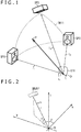
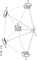
- a user U11 who enjoys a content of a moving picture with sound, a musical piece or the like is listening to sound of three-channels outputted from three speakers SP1 to SP3 as sound of the content.
- the position p is represented by a three-dimensional vector (hereinafter referred to also as vector p) whose start point is the origin O in a three-dimensional coordinate system whose origin O is given by the position of the head of the user U11.
- vector p three-dimensional vectors whose start point is given by the origin O and that are directed in directions toward the positions of the speakers SP1 to SP3 are represented as vectors I 1 to I 3 , respectively, then the vector p can be represented by a linear sum of the vectors I 1 to I 3 .
- coefficients g 1 to g 3 by which the vectors I 1 to I 3 are multiplied are calculated and are determined as gains of sound outputted from the speakers SP1 to SP3, respectively, then a sound image can be localized at the position p.
- a technique for determining the coefficients g 1 to g 3 using position information of the three speakers SP1 to SP3 and controlling the localization position of a sound image in such a manner as described above is referred to as three-dimensional VBAP.
- VBAP gain a gain determined for each speaker like the coefficients g 1 to g 3 is referred to as VBAP gain.
- a sound image can be localized at an arbitrary position in a region TR11 of a triangular shape on a sphere including the positions of the speakers SP1, SP2 and SP3.
- the region TR11 is a region on the surface of a sphere centered at the origin O and passing the positions of the speakers SP1 to SP3 and is a triangular region surrounded by the speakers SP1 to SP3.
- a bit stream obtained by multiplexing encoded audio data obtained by encoding an audio signal of each object and encoded metadata obtained by encoding metadata of each object is outputted from an encoding apparatus.
- the metadata includes position information indicative of a position of an object in a space, importance information indicative of an importance degree of the object and spread that is information indicative of a degree of extent of a sound image of the object.
- the spread indicative of an extent degree of a sound image is an arbitrary angle from 0 to 180 deg., and the encoding apparatus can designate spread of a value different for each frame of an audio signal in regard to each object.
- the position of the object is represented by a horizontal direction angle azimuth, a vertical direction angle elevation and a distance radius.
- the position information of the object is configured from values of the horizontal direction angle azimuth, vertical direction angle elevation and distance radius.
- a three-dimensional coordinate system is considered in which, as depicted in FIG. 2 , the position of a user who enjoys sound of objects outputted from speakers not depicted is determined as the origin O and a right upward direction, a left upward direction and an upward direction in FIG. 2 are determined as an x axis, a y axis and a z axis that are perpendicular to each other.
- the position of one object is represented as position OBJ11
- a sound image may be localized at the position OBJ11 in the three-dimensional coordinate system.
- the angle ⁇ (azimuth) in the horizontal direction in FIG. 2 defined by the linear line L and the x axis on the xy plane is a horizontal direction angle azimuth indicative of the position in the horizontal direction of the object at the position OBJ11
- the horizontal direction angle azimuth has an arbitrary value that satisfies -180 deg. ⁇ azimuth ⁇ 180 deg.
- the counterclockwise direction around the origin O is determined as the + direction of the azimuth and the clockwise direction around the origin O is determined as the - direction of the azimuth.
- the angle defined by the linear line L and the xy plane namely, the angle ⁇ (elevation angle) in the vertical direction in FIG. 2
- the perpendicular direction angle elevation is the perpendicular direction angle elevation indicative of the position in the vertical direction of the object located at the position OBJ11
- the perpendicular direction angle elevation has an arbitrary value that satisfies -90 deg. ⁇ elevation ⁇ 90 deg.
- the length of the linear line L namely, the distance from the origin O to the position OBJ11, is the distance radius to the user, and the distance radius has a value of 0 or more.
- the distance radius has a value that satisfies 0 ⁇ radius ⁇ ⁇ .
- the distance radius is referred to also as distance in a radial direction.
- the distance radii from all speakers or objects to the user are equal, and it is a general method that the distance radius is normalized to 1 to perform calculation.
- the position information of the object included in the metadata in this manner is configured from values of the horizontal direction angle azimuth, vertical direction angle elevation and distance radius.
- the horizontal direction angle azimuth, vertical direction angle elevation and distance radius are referred to simply also as azimuth, elevation and radius, respectively.
- a rendering process for extending a sound image is performed in response to the value of the spread included in the metadata.
- the decoding apparatus first determines a position in a space indicated by the position information included in the metadata of an object as position p.
- the position p corresponds to the position p in FIG. 1 described hereinabove.
- FIG. 3 portions corresponding to those in the case of FIG. 1 are denoted by like reference symbols, and description of the portions is omitted suitably.
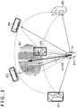
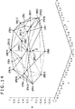
- five speakers SP1 to SP5 are disposed on a spherical plane of a unit sphere of a radius 1 centered at the origin O, and the position p indicated by the position information is the center position p0.
- the position p is specifically referred to also as object position p and the vector whose start point is the origin O and whose end point is the object position p is referred to also as vector p.
- the vector whose start point is the origin O and whose end point is the center position p0 is referred to also as vector p0.
- an arrow mark whose start point is the origin O and which is plotted by a broken line represents a spread vector. However, while there actually are 18 spread vectors, in FIG. 3 , only eight spread vectors are plotted for the visibility of FIG. 3 .
- each of the spread vectors p1 to p18 is a vector whose end point position is positioned within a region R11 of a circle on a unit spherical plane centered at the center position p0.
- the angle defined by the spread vector whose end point position is positioned on the circumference of the circle represented by the region R11 and the vector p0 is an angle indicated by the spread.
- each spread vector is disposed at a position spaced farther from the center position p0 as the value of the spread increases.
- the region R11 increases in size.
- the region R11 represents an extent of a sound image from the position of the object.
- the region R11 is a region indicative of the range in which a sound image of the object is extended. Further, it can be considered that, since it is considered that sound of the object is emitted from the entire object, the region R11 represents the shape of the object.
- a region that indicates a range in which a sound image of an object is extended like the region R11 is referred to also as region indicative of extent of a sound image.
- the end point positions of the 18 spread vectors p1 to p18 are equivalent to the center position p0.
- end point positions of the spread vectors p1 to p18 are specifically referred to also as positions p1 to p18, respectively.
- the decoding apparatus calculates a VBAP gain for each of the speakers of the channels by the VBAP in regard to the vector p and the spread vectors, namely, in regard to each of the position p and the positions p1 to p18.
- the VBAP gains for the speakers are calculated such that a sound image is localized at each of the positions such as the position p and a position p1.
- the decoding apparatus adds the VBAP gains calculated for the positions for each speaker. For example, in the example of FIG. 3 , the VBAP gains for the position p calculated in regard to the speaker SP1 and the positions p1 to p18 are added.
- the decoding apparatus normalizes the VBAP gains after the addition process calculated for the individual speakers. In particular, normalization is performed such that the square sum of the VBAP gains of all speakers becomes 1.
- the decoding apparatus multiplies the audio signal of the object by the VBAP gains of the speakers obtained by the normalization to obtain audio signals for the individual speakers, and supplies the audio signals obtained for the individual speakers to the speakers such that they output sound.
- a sound image is localized such that sound is outputted from the entire region R11.
- the sound image is extended to the entire region R11.
- the present technology makes it possible to reduce the processing amount upon rendering. Further, the present technology makes it possible to obtain sound of sufficiently high quality by representing the directionality or the shape of an object. Furthermore, the present technology makes it possible to select an appropriate process as a process upon rendering in response to a hardware scale of a renderer or the like to obtain sound having the highest quality within a range of a permissible processing amount.
- the multiplication process in the process B5 is performed by three times or more.
- the processing amount increases by an amount especially by the processes B2 and B3 and the processing amount also in the process B5 is greater than that in the process A3.
- the present technology makes it possible to reduce the processing amount in the process B5 described above by quantizing the sum of the VBAP gains of the vectors determined for each speaker.
- VBAP gain addition value the sum (addition value) of the VBAP gains calculated for each vector such as a vector p or a spread vector determined for each speaker.
- the VBAP gain addition value is binarized.
- the VBAP gain addition value for each speaker has one of 0 and 1.
- any method may be adopted such as rounding off, ceiling (round up), flooring (truncation) or a threshold value process.
- the process B4 described above is performed on the basis of the binarized VBAP gain addition value. Then, as a result, the final VBAP gain for each speaker is one gain except 0. In other words, if the VBAP gain addition value is binarized, then the final value of the VBAP gain of each speaker is 0 or a predetermined value.
- the VBAP gain addition value of the three speakers is 1 and the VBAP gain addition value of the other speakers is 0, then the final value of the VBAP gain of the three speakers is 1/3 (1/2) .
- a process for multiplying the audio signals for the speakers by the final VBAP gains is performed as a process B5' in place of the process B5 described hereinabove.
- VBAP gain addition value may be quantized otherwise into one of three values or more.
- a VBAP gain addition value is one of three values
- the processes B1 to B3 described above are performed and a VBAP gain addition value is obtained for each speaker
- the VBAP gain addition value is quantized into one of 0, 0.5 and 1.
- the process B4 and the process B5' are performed. In this case, the number of times of a multiplication process in the process B5' is two in the maximum.
- a VBAP gain addition value is x-value converted in this manner, namely, where a VBAP gain addition value is quantized into one of x gains where x is equal to or greater than 2, then the number of times of performance of a multiplication process in the process B5' becomes (x - 1) in the maximum.
- a VBAP gain addition value is quantized to reduce the processing amount
- the processing amount can be reduced by quantizing a VBAP gain similarly.
- the VBAP gain for each speaker determined in regard to the vector p is quantized, then the number of times of performance of a multiplication process for an audio signal by the VBAP gain after normalization can be reduced.
- a spread three-dimensional vector that is a three-dimensional vector is stored into and transmitted together with a bit stream.
- a spread three-dimensional vector is stored, for example, into metadata of a frame of each audio signal for each object.
- a spread indicative of an extent degree of a sound image is not stored in the metadata.
- a spread three-dimensional vector is a three-dimensional vector including three factors of s3_azimuth indicative of an extent degree of a sound image in the horizontal direction, s3_elevation indicative of an extent degree of the sound image in the vertical direction and s3_radius indicative of a depth in a radius direction of the sound image.
- the spread three-dimensional vector (s3_azimuth, s3_elevation, s3_radius).
- s3_azimuth indicates a spread angle of a sound image in the horizontal direction from the position p, namely, in a direction of the horizontal direction angle azimuth described hereinabove.
- s3_azimuth indicates an angle defined by a vector toward an end in the horizontal direction side of a region that indicates an extent of a sound image from the origin O and the vector p (vector pO).
- s3_elevation indicates a spread angle of a sound image in the vertical direction from the position p, namely, in the direction of the vertical direction angle elevation described hereinabove.
- s3_elevation indicates an angle defined between a vector toward an end in the vertical direction side of a region indicative of an extent of the sound image from the origin O and the vector p (vector pO).
- s3_radius indicates a depth in the direction of the distance radius described above, namely, in a normal direction to the unit spherical plane.
- s3_azimuth, s3_elevation and s3_radius have values equal to or greater than 0.
- the spread three-dimensional vector here is information indicative of a relative position to the position p indicated by the position information of the object, the spread three-dimensional vector may otherwise be information indicative of an absolute position.
- such a spread three-dimensional vector as described above is used to perform rendering.
- a value of the spread is calculated by calculating the expression (1) given below on the basis of a spread three-dimensional vector: [Expression 1] spread : max s 3 _ azimuth , s 3 _ elevation
- max(a, b) in the expression (1) indicates a function that returns a higher one of values of a and b. Accordingly, a higher value of s3_azimuth and s3_elevation is determined as the value of the spread.
- 18 spread vectors p1 to p18 are calculated similarly as in the case of the MPEG-H 3D Audio standard.
- the position p of the object indicated by the position information included in the metadata is determined as center position pO, and the 18 spread vectors p1 to p18 are determined such that they are symmetrical in the leftward and rightward direction and the upward and downward direction on the unit spherical plane centered at the center position pO.
- the vector pO whose start point is the origin O and whose end point is the center position pO is determined as spread vector p0.
- each spread vector is represented by a horizontal direction angle azimuth, a vertical direction angle elevation and a distance radius.
- the horizontal direction angle azimuth and the vertical direction angle elevation particularly of the spread vector pi are resented as a(i) and e(i), respectively.
- the spread vectors p0 to p18 are obtained in this manner, the spread vectors p1 to p18 are changed (corrected) into final spread vectors on the basis of the ratio between s3_azimuth and s3_elevation.
- the process of determining a greater one of s3_azimuth and s3_elevation as a spread to determine a spread vector in such a manner as described above is a process for tentatively setting a region indicative of an extent of a sound image on the unit spherical plane as a circle of a radius defined by an angle of a greater one of s3_azimuth and s3_elevation to determine a spread vector by a process similar to a conventional process.
- the process of correcting the spread vector later by the expression (2) or the expression (3) in response to a relationship in magnitude between s3_azimuth and s3_elevation is a process for correcting the region indicative of the extent of the sound image, namely, the spread vector, such that the region indicative of the extent of the sound image on the unit spherical plane becomes a region defined by original s3_azimuth and s3_elevation designated by the spread three-dimensional vector.
- the processes described above after all become processes for calculating a spread vector for a region indicative of an extent of a sound image, which has a circular shape or an elliptical shape, on the unit spherical plane on the basis of the spread three-dimensional vector, namely, on the basis of s3_azimuth and s3_elevation.
- the spread vectors p0 to p18 are thereafter used to perform the process B2, the process B3, the process B4 and the process B5' described hereinabove to generate audio signals to be supplied to the speakers.
- a VBAP gain for each speaker is calculated in regard to each of the 19 spread vectors of the spread vectors p0 to p18.
- the spread vector p0 is the vector p, it can be considered that the process for calculating the VBAP gain in regard to the spread vector p0 is to perform the process B1.
- quantization of each VBAP gain addition value is performed as occasion demands.
- the number of spread vectors to be calculated may be variable.
- the number of spread vectors to be generated can be determined, for example, in response to the ratio between s3_azimuth and s3_elevation. According to such a process as just described, for example, where an object is elongated horizontally and the extent of sound of the object in the vertical direction is small, if the spread vectors juxtaposed in the vertical direction are omitted and the spread vectors are juxtaposed substantially in the horizontal direction, then the extent of sound in the horizontal direction can be represented appropriately.
- a spread center vector that is a three-dimensional vector is stored into and transmitted together with a bit stream.
- a spread center vector is stored, for example, into metadata of a frame of each audio signal for each object.
- a spread indicative of an extent degree of a sound image is stored in the metadata.
- the spread center vector is a vector indicative of the center position pO of a region indicative of an extent of a sound image of an object.
- the spread center vector is a three-dimensional vector configured form three factors of azimuth indicative of a horizontal direction angle of the center position pO, elevation indicative of a vertical direction angle of the center position pO and radius indicative of a distance of the center position pO in a radial direction.
- the spread center vector (azimuth, elevation, radius).
- the position indicated by the spread center vector is determined as the center position pO, and spread vectors p0 to p18 are calculated as spread vectors.
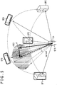
- the spread vector p0 is the vector pO whose start point is the origin O and whose end point is the center position pO. It is to be noted that, in FIG. 4 , portions corresponding to those in the case of FIG. 3 are denoted by like reference symbols and description of them is omitted suitably.
- an arrow mark plotted by a broken line represents a spread vector
- an arrow mark plotted by a broken line represents a spread vector
- the center position pO is a position different from the position p.
- a region R21 indicative of an extent of a sound image and centered at the center position pO is displaced to the left side in FIG. 4 from that in the example of FIG. 3 with respect to the position p that is the position of the object.
- the process B1 is performed thereafter for the vector p and the process B2 is performed in regard to the spread vectors p0 to p18.
- a VBAP gain may be calculated in regard to each of the 19 spread vectors, or a VBAP gain may be calculated only in regard to the spread vectors p1 to p18 except the spread vector p0. In the following, description is given assuming that a VBAP gain is calculated also in regard to the spread vector p0.
- the process B3, process B4 and process B5' are performed to generate audio signals to be supplied to the speakers. It is to be noted that, after the process B3, quantization of a VBAP gain addition value is performed as occasion demands.
- a spread end vector that is a five-dimensional vector is stored into and transmitted together with a bit stream.
- a spread end vector is stored into metadata of a frame of each audio signal for each object.
- a spread indicative of an extent degree of a sound image is not stored into the metadata.
- a spread end vector is a vector representative of a region indicative of an extent of a sound image of an object, and is a vector configured from five factors of a spread left end azimuth, a spread right end azimuth, a spread upper end elevation, a spread lower end elevation and a spread radius.
- the spread left end azimuth and the spread right end azimuth configuring the spread end vector individually indicate values of horizontal direction angles azimuth indicative of absolute positions of a left end and a right end in the horizontal direction of the region indicative of the extent of the sound image.
- the spread left end azimuth and the spread right end azimuth individually indicate angles representative of extent degrees of a sound image in the leftward direction and the rightward direction from the center position pO of the region indicative of the extent of the sound image.
- the spread upper end elevation and the spread lower end elevation individually indicate values of vertical direction angles elevation indicative of absolute positions of an upper end and a lower end in the vertical direction of the region indicative of the extent of the sound image.
- the spread upper end elevation and the spread lower end elevation individually indicate angles representative of extent degrees of a sound image in the upward direction and the downward direction from the center position pO of the region indicative of the extent of the sound image.
- spread radium indicates a depth of the sound image in a radial direction.
- the spread end vector here is information indicative of an absolute position in the space
- the spread end vector may otherwise be information indicative of a relative position to the position p indicated by the position information of the object.
- the following expression (4) is calculated on the basis of a spread end vector to calculate the center position pO: [Expression 4] azimuth : spread left end azimuth + spread right end azimuth / 2 elevation : spread upper end elevation + spread lower end elevation / 2 radius : spread radius
- the horizontal direction angle azimuth indicative of the center position pO is a middle (average) angle between the spread left end azimuth and the spread right end azimuth
- the vertical direction angle elevation indicative of the center position pO is a middle (average) angle between the spread upper end elevation and the spread lower end elevation.
- the distance radius indicative of the center position pO is spread radius.
- the center position pO sometimes becomes a position different from the position p of an object indicated by the position information.
- the value of the spread is calculated by calculating the following expression (5): [Expression 5] spread : max spread left end azimuth ⁇ spread right end azimuth / 2 , spread upper end elevation ⁇ spread lower end elevation / 2
- max(a, b) in the expression (5) indicates a function that returns a higher one of values of a and b. Accordingly, a higher one of values of (spread left end azimuth - spread right end azimuth)/2 that is an angle corresponding to the radius in the horizontal direction and (spread upper end elevation - spread lower end elevation)/2 that is an angle corresponding to the radius in the vertical direction in the region indicative of the extent of the sound image of the object indicated by the spread end vector is determined as the value of the spread.
- the 18 spread vectors p1 to p18 are calculated similarly as in the case of the MPEG-H 3D Audio standard.
- the 18 spread vectors p1 to p18 are determined such that they are symmetrical in the upward and downward direction and the leftward and rightward direction on the unit spherical plane centered at the center position pO.
- the vector pO whose start point is the origin O and whose end point is the center position pO is determined as spread vector p0.
- each spread vector is represented by a horizontal direction angle azimuth, a vertical direction angle elevation and a distance radius.
- the horizontal direction angle azimuth and the vertical direction angle elevation of a spread vector pi are represented by a(i) and e(i), respectively.
- the spread vectors p0 to p18 are obtained in this manner, the spread vectors p1 to p18 are changed (corrected) on the basis of the ratio between the (spread left end azimuth - spread right end azimuth) and the (spread upper end elevation - spread lower end elevation) to determine final spread vectors.
- the processes described above after all are processes for calculating, on the basis of the spread end vector, a spread vector for a region indicative of an extent of a sound image of a circular shape or an elliptical shape on a unit spherical plane defined by the spread end vector.
- the vector p and the spread vectors p0 to p18 are used to perform the process B1, the process B2, the process B3, the process B4 and the process B5' described hereinabove, thereby generating audio signals to be supplied to the speakers.
- a VBAP gain for each speaker is calculated in regard to the 19 spread vectors. Further, after the process B3, quantization of VBAP gain addition values is performed as occasion demands.
- a VBAP gain is calculated in regard to the spread vector p0
- the VBAP gain may not be calculated in regard to the spread vector p0.
- the following description is given assuming that a VBAP gain is calculated also in regard to the spread vector p0.
- the number of spread vectors to be generated may be determined, for example, in response to the ratio between the (spread left end azimuth - spread right end azimuth) and the (spread upper end elevation - spread lower end elevation).
- a spread radiation vector that is a three-dimensional vector is stored into and transmitted together with a bit stream.
- a spread radiation vector is stored into metadata of a frame of each audio signal for each object.
- the spread indicative of an extent degree of a sound image is stored in the metadata.
- the spread radiation vector is a vector indicative of a relative position of the center position pO of a region indicative of an extent of a sound image of an object to the position p of the object.
- the spread radiation vector is a three-dimensional vector configured from three factors of azimuth indicative of a horizontal direction angle to the center position pO, elevation indicative of a vertical direction angle to the center position pO and radius indicative of a distance in a radial direction of the center position pO, as viewed from the position p.
- the spread radiation vector (azimuth, elevation, radius).
- a position indicated by a vector obtained by adding the spread radiation vector and the vector p is determined as the center position pO, and as the spread vector, the spread vectors p0 to p18 are calculated.
- the spread vector p0 is the vector pO whose start point is the origin O and whose end point is the center position pO.
- an arrow mark plotted by a broken line represents a spread vector
- an arrow mark plotted by a broken line represents a spread vector
- the center position pO is a position different from the position p.
- the end point position of a vector obtained by vector addition of the vector p and the spread radiation vector indicated by an arrow mark B11 is the center position pO.
- a region R31 indicative of an extent of a sound image and centered at the center position pO is displaced to the left side in FIG. 5 more than that in the example of FIG. 3 with respect to the position p that is a position of the object.
- the process B1 is thereafter performed for the vector p and the process B2 is performed for the spread vectors p0 to p18.
- a VBAP gain may be calculated in regard to the 19 spread vectors or a VBAP gain may be calculated only in regard to the spread vectors p1 to p18 except the spread vector p0. In the following description, it is assumed that a VBAP gain is calculated also in regard to the spread vector p0.
- the process B3, the process B4 and the process B5' are performed to generate audio signals to be supplied to the speakers. It is to be noted that, after the process B3, quantization of each VBAP gain addition value is performed as occasion demands.
- spread vector number information indicative of the number of spread vectors for calculating a VBAP gain and spread vector position information indicative of the end point position of each spread vector are stored into and transmitted together with a bit stream.
- spread vector number information and spread vector position information are stored, for example, into metadata of a frame of each audio signal for each object.
- the spread indicative of an extent degree of a sound image is not stored into the metadata.
- a vector whose start point is the origin O and whose end point is a position indicated by the spread vector position information is calculated as spread vector.
- the process B1 is performed in regard to the vector p and the process B2 is performed in regard to each spread vector. Further, after a VBAP gain for each vector is calculated, the process B3, the process B4 and the process B5' are performed to generate audio signals to be supplied to the speakers. It is to be noted that, after the process B3, quantization of each VBAP gain addition value is performed as occasion demands.
- an index for switching a process is stored into and transmitted together with a bit stream from an encoding apparatus to a decoding apparatus.
- an index value index for switching a process is added to a bit stream syntax.
- the following process is performed in response to the value of the index value index.
- index value index 1, from among combinations of indexes indicative of 18 spread vectors according to the conventional MPEG-H 3D Audio standard, indexes of a predetermined combination are stored into and transmitted together with a bit stream.
- the renderer calculates a VBAP gain in regard to a spread vector indicated by each index stored in and transmitted together with the bit stream.
- index value index 2
- information indicative of the number of spread vectors to be used in processing and an index indicative of which one of the 18 spread vectors according to the conventional MPEG-H 3D Audio standard is indicated by a spread vector to be used for processing are stored into and transmitted together with a bit stream.
- index value index for switching a process in the encoding apparatus may not be designated, but a process may be selected by the renderer in the decoding apparatus.
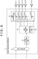
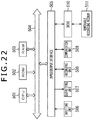
- FIG. 6 is a view depicting an example of a configuration of an audio processing apparatus to which the present technology is applied.
- speakers 12-1 to 12-M individually corresponding to M channels are connected.
- the audio processing apparatus 11 generates audio signals of different channels on the basis of an audio signal and metadata of an object supplied from the outside and supplies the audio signals to the speakers 12-1 to 12-M such that sound is reproduced by the speakers 12-1 to 12-M.
- each of the speakers 12 is a sound outputting unit that outputs sound on the basis of an audio signal supplied thereto.
- the speakers 12 are disposed so as to surround a user who enjoys a content or the like.
- the speakers 12 are disposed on a unit spherical plane described hereinabove.
- the audio processing apparatus 11 includes an acquisition unit 21, a vector calculation unit 22, a gain calculation unit 23 and a gain adjustment unit 24.
- the acquisition unit 21 acquires audio signals of objects from the outside and metadata for each frame of the audio signals of each object.
- the audio data and the metadata are obtained by decoding encoded audio data and encoded metadata included in a bit stream outputted from an encoding apparatus by a decoding apparatus.
- the acquisition unit 21 supplies the acquired audio signals to the gain adjustment unit 24 and supplies the acquired metadata to the vector calculation unit 22.
- the metadata includes, for example, position information indicative of the position of the objects, importance information indicative of an importance degree of each object, spread indicative of a spatial extent of the sound image of the object and so forth as occasion demands.
- the vector calculation unit 22 calculates spread vectors on the basis of the metadata supplied thereto from the acquisition unit 21 and supplies the spread vectors to the gain calculation unit 23. Further, as occasion demands, the vector calculation unit 22 supplies the position p of each object indicated by the position information included in the metadata, namely, also a vector p indicative of the position p, to the gain calculation unit 23.
- the gain calculation unit 23 calculates a VBAP gain of a speaker 12 corresponding to each channel by the VBAP on the basis of the spread vectors and the vector p supplied from the vector calculation unit 22 and supplies the VBAP gains to the gain adjustment unit 24. Further, the gain calculation unit 23 includes a quantization unit 31 for quantizing the VBAP gain for each speaker.
- the gain adjustment unit 24 performs, on the basis of each VBAP gain supplied from the gain calculation unit 23, gain adjustment for an audio signal of an object supplied from the acquisition unit 21 and supplies the audio signals of the M channels obtained as a result of the gain adjustment to the speakers 12.
- the gain adjustment unit 24 includes amplification units 32-1 to 32-M.
- the amplification units 32-1 to 32-M multiply an audio signal supplied from the acquisition unit 21 by VBAP gains supplied from the gain calculation unit 23 and supply audio signals obtained by the multiplication to the speakers 12-1 to 12-M so as to reproduce sound.
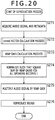
- the audio processing apparatus 11 performs a reproduction process to reproduce sound of the object.
- the acquisition unit 21 acquires an audio signal and metadata for one frame of an object from the outside and supplies the audio signal to the amplification unit 32 while it supplies the metadata to the vector calculation unit 22.
- the vector calculation unit 22 performs a spread vector calculation process on the basis of the metadata supplied from the acquisition unit 21 and supplies spread vectors obtained as a result of the spread vector calculation process to the gain calculation unit 23. Further, as occasion demands, the vector calculation unit 22 supplies also the vector p to the gain calculation unit 23.
- spread vectors are calculated by the spread three-dimensional vector method, the spread center vector method, the spread end vector method, the spread radiation vector method or the arbitrary spread vector method.
- the gain calculation unit 23 calculates the VBAP gains for the individual speakers 12 on the basis of location information indicative of the locations of the speakers 12 retained in advance and the spread vectors and the vector p supplied from the vector calculation unit 22.
- a VBAP gain for each speaker 12 is calculated. Consequently, for each of the spread vectors and vectors p, a VBAP gain for one or more speakers 12 positioned in the proximity of the position of the object, namely, positioned in the proximity of the position indicated by the vector is obtained. It is to be noted that, although the VBAP gain for the spread vector is calculated without fail, if a vector p is not supplied from the vector calculation unit 22 to the gain calculation unit 23 by the process at step S12, then the VBAP gain for the vector p is not calculated.
- the gain calculation unit 23 adds the VBAP gains calculated in regard to each vector to calculate a VBAP gain addition value for each speaker 12.
- a VBAP gain addition value for each speaker 12.
- an addition value (sum total) of the VBAP gains of the vectors calculated for the same speaker 12 is calculated as the VBAP gain addition value.
- the quantization unit 31 decides whether or not binarization of the VBAP gain addition value is to be performed.
- Whether or not binarization is to be performed may be decided, for example, on the basis of the index value index described hereinabove or may be decided on the basis of the importance degree of the object indicated by the importance information as the metadata.
- the index value index read out from a bit stream may be supplied to the gain calculation unit 23.
- the importance information may be supplied from the vector calculation unit 22 to the gain calculation unit 23.
- step S15 If it is decided at step S15 that binarization is to be performed, then at step S16, the quantization unit 31 binarizes the addition value of the VBAP gains determined for each speaker 12, namely, the VBAP gain addition value. Thereafter, the processing advances to step S17.
- step S15 if it is decided at step S15 that binarization is not to be performed, then the process at step S16 is skipped and the processing advances to step S17.
- the gain calculation unit 23 normalizes the VBAP gain for each speaker 12 such that the square sum of the VBAP gains of all speakers 12 may become 1.
- normalization of the addition value of the VBAP gains determined for each speaker 12 is performed such that the square sum of all addition values may become 1.
- the gain calculation unit 23 supplies the VBAP gains for the speakers 12 obtained by the normalization to the amplification units 32 corresponding to the individual speakers 12.
- the amplification unit 32 multiplies the audio signal supplied from the acquisition unit 21 by the VBAP gains supplied from the gain calculation unit 23 and supplies resulting values to the speaker 12.
- the amplification unit 32 causes the speakers 12 to reproduce sound on the basis of the audio signals supplied thereto, thereby ending the reproduction process. Consequently, a sound image of the object is localized in a desired partial space in the reproduction space.
- the audio processing apparatus 11 calculates spread vectors on the basis of metadata, calculates a VBAP gain for each vector for each speaker 12 and determines and normalizes an addition value of the VBAP gains for each speaker 12.
- VBAP gains in regard to the spread vectors in this manner, a spatial extent of a sound image of the object, especially, a shape of the object or a directionality of sound can be represented, and sound of higher quality can be obtained.
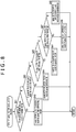
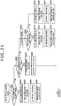
- the vector calculation unit 22 decides whether or not a spread vector is to be calculated on the basis of a spread three-dimensional vector.
- which method is used to calculate a spread vector may be decided on the basis of the index value index similarly as in the case at step S15 of FIG. 7 or may be decided on the basis of the importance degree of the object indicated by the importance information.
- step S41 If it is decided at step S41 that a spread vector is to be calculated on the basis of a spread three-dimensional vector, namely, if it is decided that a spread vector is to be calculated by the spread three-dimensional method, then the processing advances to step S42.
- the vector calculation unit 22 performs a spread vector calculation process based on a spread three-dimensional vector and supplies resulting vectors to the gain calculation unit 23. It is to be noted that details of the spread vector calculation process based on spread three-dimensional vectors are hereinafter described.
- step S13 of FIG. 7 After spread vectors are calculated, the spread vector calculation process is ended, and thereafter, the processing advances to step S13 of FIG. 7 .
- step S41 if it is decided at step S41 that a spread vector is not to be calculated on the basis of a spread three-dimensional vector, then the processing advances to step S43.
- the vector calculation unit 22 decides whether or not a spread vector is to be calculated on the basis of a spread center vector.
- step S43 If it is decided at step S43 that a spread vector is to be calculated on the basis of a spread center vector, namely, if it is decided that a spread vector is to be calculated by the spread center vector method, then the processing advances to step S44.
- the vector calculation unit 22 performs a spread vector calculation process on the basis of a spread center vector and supplies resulting vectors to the gain calculation unit 23. It is to be noted that details of the spread vector calculation process based on the spread center vector are hereinafter described.
- the spread vector calculation process is ended, and thereafter, the processing advances to step S13 of FIG. 7 .
- step S43 if it is decided at step S43 that a spread vector is not to be calculated on the basis of a spread center vector, then the processing advances to step S45.
- the vector calculation unit 22 decides whether or not a spread vector is to be calculated on the basis of a spread end vector.
- step S45 If it is decided at step S45 that a spread vector is to be calculated on the basis of a spread end vector, namely, if it is decided that a spread vector is to be calculated by the spread end vector method, then the processing advances to step S46.
- the vector calculation unit 22 performs a spread vector calculation process based on a spread end vector and supplies resulting vectors to the gain calculation unit 23. It is to be noted that details of the spread vector calculation process based on the spread end vector are hereinafter described.
- step S13 of FIG. 7 After spread vectors are calculated, the spread vector calculation process is ended, and thereafter, the processing advances to step S13 of FIG. 7 .
- step S45 if it is decided at step S45 that a spread vector is not to be calculated on the basis of the spread end vector, then the processing advances to step S47.
- the vector calculation unit 22 decides whether or not a spread vector is to be calculated on the basis of a spread radiation vector.
- step S47 If it is decided at step S47 that a spread vector is to be calculated on the basis of a spread radiation vector, namely, if it is decided that a spread vector is to be calculated by the spread radiation vector method, then the processing advances to step S48.
- the vector calculation unit 22 performs a spread vector calculation process based on a spread radiation vector and supplies resulting vectors to the gain calculation unit 23. It is to be noted that details of the spread vector calculation process based on a spread radiation vector are hereinafter described.
- step S13 of FIG. 7 After spread vectors are calculated, the spread vector calculation process is ended, and thereafter, the processing advances to step S13 of FIG. 7 .
- step S47 if it is decided at step S47 that a spread vector is not to be calculated on the basis of a spread radiation vector, namely, if it is decided that a spread vector is to be calculated by the spread radiation vector method, then the processing advances to step S49.
- the vector calculation unit 22 performs a spread vector calculation process based on the spread vector position information and supplies a resulting vector to the gain calculation unit 23. It is to be noted that details of the spread vector calculation process based on the spread vector position information are hereinafter described.
- step S13 of FIG. 7 After spread vectors are calculated, the spread vector calculation process is ended, and thereafter, the processing advances to step S13 of FIG. 7 .
- the audio processing apparatus 11 calculates spread vectors by an appropriate one of the plurality of methods in this manner. By calculating spread vectors by an appropriate method in this manner, sound of the highest quality within the range of a permissible processing amount can be obtained in response to a hardware scale of a renderer and so forth.
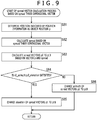
- the vector calculation unit 22 determines a position indicated by position information included in metadata supplied from the acquisition unit 21 as object position p.
- a vector indicative of the position p is the vector p.
- the vector calculation unit 22 calculates a spread on the basis of a spread three-dimensional vector included in the metadata supplied from the acquisition unit 21.
- the vector calculation unit 22 calculates the expression (1) given hereinabove to calculate a spread.
- the vector calculation unit 22 calculates spread vectors p0 to p18 on the basis of the vector p and the spread.
- the vector p is determined as vector p0 indicative of the center position p0, and the vector p is determined as it is as spread vector p0.
- vectors p1 to p18 vectors are calculated so as to be symmetrical in the upward and downward direction and the leftward and rightward direction within a region centered at the center position pO and defined by an angle indicated by the spread on the unit spherical plane similarly as in the case of the MPEG-H 3D Audio standard.
- the vector calculation unit 22 decides on the basis of the spread three-dimensional vector whether or not s3_azimuth ⁇ s3_elevation is satisfied, namely, whether or not s3_azimuth is greater than s3_elevation.
- step S85 the vector calculation unit 22 changes elevation of the spread vectors p1 to p18.
- the vector calculation unit 22 performs calculation of the expression (2) described hereinabove to correct elevation of the spread vectors to obtain final spread vectors.
- the vector calculation unit 22 supplies the spread vectors p0 to p18 to the gain calculation unit 23, thereby ending the spread vector calculation process based on the spread three-dimensional vector. Since the process at step S42 of FIG. 8 ends therewith, the processing thereafter advances to step S13 of FIG. 7 .
- the vector calculation unit 22 changes azimuth of the spread vectors p1 to p18.
- the vector calculation unit 22 performs calculation of the expression (3) given hereinabove to correct azimuths of the spread vectors thereby to obtain final spread vectors.
- the vector calculation unit 22 supplies the spread vectors p0 to p18 to the gain calculation unit 23, thereby ending the spread vector calculation process based on the spread three-dimensional vector. Consequently, since the process at step S42 of FIG. 8 ends, the processing thereafter advances to step S13 of FIG. 7 .
- the audio processing apparatus 11 calculates each spread vector by the spread three-dimensional vector method in such a manner as described above. Consequently, it becomes possible to represent the shape of the object and the directionality of sound of the object and obtain sound of higher quality.
- a process at step S111 is similar to the process at step S81 of FIG. 9 , and therefore, description of it is omitted.
- the vector calculation unit 22 calculates spread vectors p0 to p18 on the basis a spread center vector and a spread included in metadata supplied from the acquisition unit 21.
- the vector calculation unit 22 sets the position indicated by the spread center vector as center position pO and sets the vector indicative of the center position pO as spread vector p0. Further, the vector calculation unit 22 determines spread vectors p1 to p18 such that they are positioned symmetrical in the upward and downward direction and the leftward and rightward direction within a region centered at the center position pO and defined by an angle indicated by the spread on the unit spherical plane.
- the spread vectors p1 to p18 are determined basically similarly as in the case of the MPEG-H 3D Audio standard.
- the vector calculation unit 22 supplies the vector p and the spread vectors p0 to p18 obtained by the processes described above to the gain calculation unit 23, thereby ending the spread vector calculation process based on the spread center vector. Consequently, the process at step S44 of FIG. 8 ends, and thereafter, the processing advances to step S13 of FIG. 7 .
- the audio processing apparatus 11 calculates a vector p and spread vectors by the spread center vector method in such a manner as described above. Consequently, it becomes possible to represent the shape of an object and the directionality of sound of the object and obtain sound of higher quality.
- the spread vector p0 may not be supplied to the gain calculation unit 23.
- the VBAP gain may not be calculated in regard to the spread vector p0.
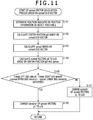
- a process at step S141 is similar to the process at step S81 of FIG. 9 , and therefore, description of it is omitted.
- the vector calculation unit 22 calculates the center position pO, namely, the vector pO, on the basis of a spread end vector included in metadata supplied from the acquisition unit 21.
- the vector calculation unit 22 calculates the expression (4) given hereinabove to calculate the center position pO.
- the vector calculation unit 22 calculates a spread on the basis of the spread end vector.
- the vector calculation unit 22 calculates the expression (5) given hereinabove to calculate a spread.
- the vector calculation unit 22 calculates spread vectors p0 to p18 on the basis of the center position pO and the spread.
- the vector pO indicative of the center position pO is set as it is as spread vector p0.
- the spread vectors p1 to p18 are calculated such that they are positioned symmetrical in the upward and downward direction and the leftward and rightward direction within a region centered at the center position pO and defined by an angle indicated by the spread on the unit spherical plane similarly as in the case of the MPEG-H 3D Audio standard.
- the vector calculation unit 22 decides whether or not (spread left end azimuth - spread right end azimuth) ⁇ (spread upper end elevation - spread lower end elevation) is satisfied, namely, whether or not the (spread left end azimuth - spread right end azimuth) is greater than the (spread upper end elevation - spread lower end elevation).
- step S145 If it is decided at step S145 that (spread left end azimuth - spread right end azimuth) ⁇ (spread upper end elevation - spread lower end elevation) is satisfied, then at step S146, the vector calculation unit 22 changes elevation of the spread vectors p1 to p18. In particular, the vector calculation unit 22 performs calculation of the expression (6) given hereinabove to correct elevations of the spread vectors to obtain final spread vectors.
- the vector calculation unit 22 supplies the spread vectors p0 to p18 and the vector p to the gain calculation unit 23, thereby ending the spread vector calculation process based on the spread end vector. Consequently, the process at step S46 of FIG. 8 ends, and thereafter, the processing advances to step S13 of FIG. 7 .
- step S145 if it is decided at step S145 that (spread left end azimuth - spread right end azimuth) ⁇ (spread upper end elevation - spread lower end elevation) is not satisfied, then the vector calculation unit 22 changes azimuth of the spread vectors p1 to p18 at step S147.
- the vector calculation unit 22 performs calculation of the expression (7) given hereinabove to correct azimuth of the spread vectors to obtain final spread vectors.
- the vector calculation unit 22 supplies the spread vectors p0 to p18 and the vector p to the gain calculation unit 23, thereby to end the spread vector calculation process based on the spread end vector. Consequently, the process at step S46 of FIG. 8 ends, and thereafter, the processing advances to step S13 of FIG. 7 .
- the audio processing apparatus 11 calculates spread vectors by the spread end vector method. Consequently, it becomes possible to represent a shape of an object and a directionality of sound of the object and obtain sound of higher quality.
- the spread vector p0 may not be supplied to the gain calculation unit 23.
- the VBAP gain may not be calculated in regard to the spread vector p0.
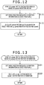
- a process at step S171 is similar to the process at step S81 of FIG. 9 and, therefore, description of the process is omitted.
- the vector calculation unit 22 calculates spread vectors p0 to p18 on the basis of a spread radiation vector and a spread included in metadata supplied from the acquisition unit 21.
- the vector calculation unit 22 sets a position indicated by a vector obtained by adding a vector p indicative of an object position p and the radiation vector as center position pO.
- the vector indicating this center portion pO is the vector pO, and the vector calculation unit 22 sets the vector pO as it is as spread vector p0.
- the vector calculation unit 22 determines spread vectors p1 to p18 such that they are positioned symmetrical in the upward and downward direction and the leftward and rightward direction within a region centered at the center position pO and defined by an angle indicated by the spread on the unit spherical plane.
- the spread vectors p1 to p18 are determined basically similarly as in the case of the MPEG-H 3D Audio standard.
- the vector calculation unit 22 supplies the vector p and the spread vectors p0 to p18 obtained by the processes described above to the gain calculation unit 23, thereby ending the spread vector calculation process based on a spread radiation vector. Consequently, since the process at step S48 of FIG. 8 ends, the processing thereafter advances to step S13 of FIG. 7 .
- the audio processing apparatus 11 calculates the vector p and the spread vectors by the spread radiation vector method in such a manner as described above. Consequently, it becomes possible to represent a shape of an object and a directionality of sound of the object and obtain sound of higher quality.
- the spread vector p0 may not be supplied to the gain calculation unit 23.
- the VBAP gain may not be calculated in retard to the spread vector p0.
- a process at step S201 is similar to the process at step S81 of FIG. 9 , and therefore, description of it is omitted.
- the vector calculation unit 22 calculates spread vectors on the basis of spread vector number information and spread vector position information included in metadata supplied from the acquisition unit 21.
- the vector calculation unit 22 calculates a vector that has a start point at the origin O and has an end point at a position indicated by the spread vector position information as spread vector.
- the number of spread vectors equal to a number indicated by the spread vector number information is calculated.
- the vector calculation unit 22 supplies the vector p and the spread vectors obtained by the processes described above to the gain calculation unit 23, thereby ending the spread vector calculation process based on spread vector position information. Consequently, since the process at step S49 of FIG. 8 ends, the processing thereafter advances to step S13 of FIG. 7 .
- the audio processing apparatus 11 calculates the vector p and the spread vectors by the arbitrary spread vector method in such a manner as described above. Consequently, it becomes possible to represent a shape of an object and a directionality of sound of the object and obtain sound of higher quality.
- VBAP is known as a technology for controlling localization of a sound image using a plurality of speakers, namely, for performing a rendering process, as described above.
- a sound image can be localized at an arbitrary point on the inner side of a triangle configured from the three speakers.
- a triangle configured especially from such three speakers is called mesh.
- the rendering process by the VBAP is performed for each object, in the case where the number of objects is great such as, for example, in a game, the processing amount of the rendering process is great. Therefore, a renderer of a small hardware scale may not be able to perform rendering for all objects, and as a result, sound only of a limited number of objects may be reproduced. This may damage the presence or the sound quality upon sound reproduction.
- the present technology makes it possible to reduce the processing amount of a rendering process while deterioration of the presence or the sound quality is suppressed.
- the number of speakers for which a VBAP gain is substantially calculated is three and the VBAP gain for each speaker is calculated for each of samples that configure an audio signal, in the multiplication process in the process A3, multiplication is performed by the number of times equal to (sample number of audio signal ⁇ 3) .
- a quantization process is described.
- a binarization process and a ternarization process are described.
- a VBAP gain obtained for each speaker by the process A1 is binarized.
- a VBAP gain for each speaker is represented by one of 0 and 1.
- the method for binarizing a VBAP gain may be any method such as rounding off, ceiling (round up), flooring (truncation) or a threshold value process.
- the process A2 and the process A3 are performed to generate audio signals for the speakers.
- the final VBAP gains for the speakers become one value other than 0 similarly as upon quantization of a spread vector described hereinabove.
- the values of the final VBAP gains of the speakers are either 0 or a predetermined value.
- multiplication may be performed by (sample number of audio signal ⁇ 1) times, and therefore the processing amount of the rendering process can be reduced significantly.
- the VBAP gains obtained for the speakers may be ternarized.
- the VBAP gain obtained for each speaker by the process A1 is ternarized into one of values of 0, 0.5 and 1.
- the process A2 and the process A3 are thereafter performed to generate audio signals for the speakers.
- the multiplication time number in the multiplication process in the process A3 becomes (sample number of audio signal ⁇ 2) in the maximum, the processing amount of the rendering process can be reduced significantly.
- a VBAP gain may be quantized into 4 or more values.
- a VBAP gain is quantized such that it has one of x gains equal to or greater than 2, or in other words, if a VBAP gain is quantized by a quantization number x, then the number of times of the multiplication process in the process A3 becomes (x - 1) in the maximum.
- the processing amount of the rendering process can be reduced by quantizing a VBAP gain in such a manner as described above. If the processing amount of the rendering process decreases in this manner, then even in the case where the number of objects is great, it becomes possible to perform rendering for all objects, and therefore, deterioration of the presence or the sound quality upon sound reproduction can be suppressed to a low level. In other words, the processing amount of the rendering process can be reduced while deterioration of the presence or the sound quality is suppressed.
- a vector p indicative of the position p of a sound image of an object of a processing target is represented by a linear sum of vectors I 1 to I 3 directed in the directions of the three speakers SP1 to SP3, and coefficients g 1 to g 3 by which the vectors are multiplied are VBAP gains for the speakers.
- a triangular region TR11 surrounded by the speakers SP1 to SP3 forms one mesh.
- p 1 , p 2 and p 3 in the expression (8) indicate an x coordinate, a y coordinate and a z coordinate on a Cartesian coordinate system indicative of the position of the sound image of the object, namely, on the three-dimensional coordinate system depicted in FIG. 2 .
- I 11 , I 12 and I 13 are values of an x component, a y component and a z component in the case where the vector I 1 directed to the first speaker SP1 configuring the mesh is decomposed into components on the x axis, y axis and z axis, and correspond to an x coordinate, a y coordinate and a z coordinate of the first speaker SP1, respectively.
- I 21 , I 22 and I 23 are values of an x component, a y component and a z component in the case where the vector I 2 directed to the second speaker SP2 configuring the mesh is decomposed into components on the x axis, y axis and z axis, respectively.
- I 31 , I 32 and I 33 are values of an x component, a y component and a z component in the case where the vector I 3 directed to the third speaker SP3 configuring the mesh is decomposed into components on the x axis, y axis and z axis, respectively.
- a plurality of speakers are disposed on a unit sphere, and one mesh is configured from three speakers from among the plurality of speakers.
- the overall surface of the unit sphere is basically covered with a plurality of meshes without a gap left therebetween. Further, the meshes are determined such that they do not overlap with each other.
- the VBAP In the VBAP, if sound is outputted from two or three speakers that configure one mesh including a position p of an object from among speakers disposed on the surface of a unit sphere, then a sound image can be localized at the position p, and therefore, the VBAP gain of the speakers other than the speakers configuring the mesh is 0.
- one mesh including the position p of the object may be specified to calculate a VBAP gain for the speakers that configure the mesh. For example, whether or not a predetermined mesh is a mesh including the position p can be decided from the calculated VBAP gains.
- the mesh is a mesh including the position p of the object.
- the calculated VBAP gain is not a correct VBAP gain.
- the meshes are selected one by one as a mesh of a processing target, and calculation of the expression (8) given hereinabove is performed for the mesh of the processing target to calculate a VBAP gain for each speaker configuring the mesh.
- the VBAP gains of the speakers configuring the mesh are determined as calculated VBAP gains while the VBAP gains of the other speakers are set to 0. Consequently, the VBAP gains for all speakers are obtained.
- a process of successively selecting a mesh of a processing target until all of VBAP gains for speakers configuring a mesh indicate values equal to or higher than 0 and calculating VBAP gains of the mesh is repeated.
- the processing amount of processes required to specify a mesh including the position p, namely, to obtain a correct VBAP gain increases.
- the 22 speakers are disposed on the surface of the unit sphere in this manner, if meshes are formed such that they cover the unit sphere surface using all of the 22 speakers, then the total number of meshes on the unit sphere is 40.
- the total number of meshes on the unit sphere is eight, and the total number of meshes can be reduced significantly.
- the processing amount when VBAP gains are calculated can be reduced to 8/40 times, and the processing amount can be reduced significantly.
- the mesh number switching process determines whether the total number of meshes is changed by the mesh number switching process. If the total number of meshes is changed by the mesh number switching process, then when speakers to be used to form the number of meshes after the change are selected, it is desirable to select speakers whose positions in the vertical direction (upward and downward direction) as viewed from the user who is at the origin O, namely, whose positions in the direction of the vertical direction angle elevation are different from each other. In other words, it is desirable to use three or more speakers including speakers positioned at different heights from each other to form the number of meshes after the change. This is because it is intended to suppress deterioration of the three-dimensional sense, namely, the presence, of sound.
- FIG. 16 a case is considered in which some or all of five speakers including the speakers SP1 to SP5 disposed on a unit sphere surface are used to form meshes as depicted in FIG. 16 . It is to be noted that, in FIG. 16 , portions corresponding to those in the case of FIG. 3 are denoted by like reference symbols and description of them is omitted.
- the number of meshes is three.
- three regions including a region of a triangular shape surrounded by the speakers SP1 to SP3, another region of a triangular shape surrounded by the speakers SP2 to SP4 and a further region of a triangular shape surrounded by the speakers SP2, SP4 and SP5 form meshes.
- the mesh does not form a triangular shape but forms a two-dimensional arc.
- a sound image of an object can be localized only on the arc interconnecting the speakers SP1 and SP2 or on the arc interconnecting the speakers SP2 and SP5 of the unit sphere.
- the speaker SP1 and the speakers SP3 to SP5 from among the speakers SP1 to SP5 are used, then two meshes can be formed such that they cover the overall unit sphere surface.
- the speakers SP1 and SP5 and the speakers SP3 and SP4 are positioned at heights different from each other.
- a region of a triangular shape surrounded by the speakers SP1, SP3 and SP5 and another region of a triangular shape surrounded by the speakers SP3 to SP5 are formed as meshes.
- the top speaker is the speaker SPK19 depicted in FIG. 14 .
- some of the processes described as a quantization process or a mesh number switching process may be used fixedly, or such processes may be switched or may be combined suitably.
- which processes are to be performed in combination may be determined on the basis of the total number of objects (hereinafter referred to as object number), importance information included in metadata of an object, a sound pressure of an audio signal of an object or the like. Further, it is possible to perform combination of processes, namely, switching of a process, for each object or for each frame of an audio signal.
- the object number is equal to or greater than 10
- a binarization process for a VBAP gain is performed for all objects.
- the object number is smaller than 10
- only the process A1 to the process A3 described hereinabove are performed as usual.
- a mesh number switching process may be performed in response to the object number to change the total number of meshes appropriately.
- the total number of meshes may be set among multiple stages in response to the object number such that the total number of meshes decreases as the object number increases.
- a mesh number switching process may be performed in response to the value of the importance information of the object to change the total number of messes appropriately.
- the total number of meshes may be increased as the importance degree of the object increases, and the total number of meshes can be changed among multiple stages.
- the process can be switched for each object on the basis of the importance information of each object.
- it is possible to increase the sound quality in regard to an object having a high importance degree but decrease the sound quality in regard to an object having a low importance degree thereby to reduce the processing amount. Accordingly, when sound of objects of various importance degrees are to be reproduced simultaneously, sound quality deterioration on the auditory sensation is suppressed most to reduce the processing amount, and it can be considered that this is a technique that is well-balanced between assurance of sound quality and processing amount reduction.
- the total number of meshes may be increased for an object positioned at a position near to an object that has a higher importance degree, namely, an object whose value of the importance information is equal to or higher than a predetermined value or the quantization process may not be performed.
- the total number of meshes is set to 40, but in regard to an object whose importance information does not indicate the highest value, the total number of meshes is decreased.
- the total number of meshes may be increased as the distance between the object and an object whose importance information is the highest value decreases.
- the total number of meshes may be increased as the distance between the object and an object whose importance information is the highest value decreases.
- a process may be switched in response to a sound pressure of an audio signal of an object.
- the sound pressure of an audio signal can be determined by calculating a square root of a mean squared value of sample values of samples in a frame of a rendering target of an audio signal.
- N represents the number of samples configuring a frame of an audio signal
- a mesh number switching process may be performed in response to the sound pressure RMS of an audio signal of an object such that the total number of meshes is changed appropriately.
- the total number of meshes may be increased as the sound pressure RMS of the object increases, and the total number of meshes can be changed among multiple stages.
- a combination of a quantization process or a mesh number switching process may be selected in response to the object number, the importance information and the sound pressure RMS.
- a VBAP gain may be calculated by a process according to a result of selection, on the basis of the object number, the importance information and the sound pressure RMS, of whether or not a quantization process is to be performed, into how many gains a VBAP gain is to be quantized in the quantization process, namely, the quantization number upon the quantization processing, and the total number of meshes to be used for calculation of a VBAP gain.
- a process as given below can be performed.
- the total number of meshes is set to 10 and besides a binarization process is performed.
- the processing amount is reduced by reducing the total number of meshes and performing a binarization process. Consequently, even where the hardware scale of a renderer is small, rendering of all objects can be performed.
- the object number is smaller than 10 and besides the value of the importance information is not the highest value and besides the sound pressure RMS is equal to or higher than -30 dB
- the total number of meshes is set to 10 and besides a ternarization process is performed. This makes it possible to reduce the processing amount upon rendering processing to such a degree that, in regard to sound that has a high sound pressure although the importance degree is low, sound quality deterioration of the sound does not stand out.
- the total number of meshes is set to 5 and further a binarization process is performed. This makes it possible to sufficiently reduce the processing amount upon rendering processing in regard to sound that has a low importance degree and has a low sound pressure.
- FIG. 17 is a view depicting an example of a particular configuration of such an audio processing apparatus as just described. It is to be noted that, in FIG. 17 , portions corresponding to those in the case of FIG. 6 are denoted by like reference symbols and description of them is omitted suitably.
- the audio processing apparatus 61 depicted in FIG. 17 includes an acquisition unit 21, a gain calculation unit 23 and a gain adjustment unit 71.
- the gain calculation unit 23 receives metadata and audio signals of objects supplied from the acquisition unit 21, calculates a VBAP gain for each of the speakers 12 for each object and supplies the calculated VBAP gains to the gain adjustment unit 71.
- the gain calculation unit 23 includes a quantization unit 31 that performs quantization of the VBAP gains.
- the gain adjustment unit 71 multiplies an audio signal supplied from the acquisition unit 21 by the VBAP gains for the individual speakers 12 supplied from the gain calculation unit 23 for each object to generate audio signals for the individual speakers 12 and supplies the audio signals to the speakers 12.
- an audio signal and metadata of one object or each of a plurality of objects are supplied for each frame to the acquisition unit 21 and a reproduction process is performed for each frame of an audio signal of each object.
- the acquisition unit 21 acquires an audio signal and metadata of an object from the outside and supplies the audio signal to the gain calculation unit 23 and the gain adjustment unit 71 while it supplies the metadata to the gain calculation unit 23. Further, the acquisition unit 21 acquires also information of the number of objects with regard to which sound is to be reproduced simultaneously in a frame that is a processing target, namely, of the object number and supplies the information to the gain calculation unit 23.
- the gain calculation unit 23 decides whether or not the object number is equal to or greater than 10 on the basis of the information representative of an object number supplied from the acquisition unit 21.
- the gain calculation unit 23 sets the total number of meshes to be used upon VBAP gain calculation to 10 at step S233. In other words, the gain calculation unit 23 selects 10 as the total number of meshes.
- the gain calculation unit 23 selects a predetermined number of speakers 12 from among all of the speakers 12 in response to the selected total number of meshes such that the number of meshes equal to the total number are formed on the unit spherical surface. Then, the gain calculation unit 23 determines 10 meshes on the unit spherical surface formed from the selected speakers 12 as meshes to be used upon VBAP gain calculation.
- the gain calculation unit 23 calculates a VBAP gain for each speaker 12 by the VBAP on the basis of location information indicative of locations of the speakers 12 configuring the 10 meshes determined at step S233 and position information included in the metadata supplied from the acquisition unit 21 and indicative of the positions of the objects.
- the gain calculation unit 23 successively performs calculation of the expression (8) using the meshes determined at step S233 in order as a mesh of a processing target to calculate the VBAP gain of the speakers 12.
- a new mesh is successively determined as a mesh of the processing target until the VBAP gains calculated in regard to three speakers 12 configuring the mesh of the processing target all indicate values equal to or greater than 0 to successively calculate VBAP gains.
- step S235 the quantization unit 31 binarizes the VBAP gains of the speakers 12 obtained at step S234, whereafter the processing advances to step S246.
- step S232 If it is decided at step S232 that the object number is smaller than 10, then the processing advances to step S236.
- the gain calculation unit 23 decides whether or not the value of the importance information of the objects included in the metadata supplied from the acquisition unit 21 is the highest value. For example, if the value of the importance information is the value "7" indicating that the importance degree is highest, then it is decided that the importance information indicates the highest value.
- step S236 If it is decided at step S236 that the importance information indicates the highest value, then the processing advances to step S237.
- the gain calculation unit 23 calculates a VBAP gain for each speaker 12 on the basis of the location information indicative of the locations of the speakers 12 and the position information included in the metadata supplied from the acquisition unit 21, whereafter the processing advances to step S246.
- the meshes formed from all speakers 12 are successively determined as a mesh of a processing target, and a VBAP gain is calculated by calculation of the expression (8).
- the gain calculation unit 23 calculates the sound pressure RMS of the audio signal supplied from the acquisition unit 21.
- calculation of the expression (10) given hereinabove is performed for a frame of the audio signal that is a processing target to calculate the sound pressure RMS.
- the gain calculation unit 23 decides whether or not the sound pressure RMS calculated at step S238 is equal to or higher than -30 dB.
- step S239 If it is decided at step S239 that the sound pressure RMS is equal to or higher than -30 dB, then processes at steps S240 and S241 are performed. It is to be noted that the processes at steps S240 and S241 are similar to those at steps S233 and S234, respectively, and therefore, description of them is omitted.
- step S242 the quantization unit 31 ternarizes the VBAP gain for each speaker 12 obtained at step S241, whereafter the processing advances to step S246.
- step S239 if it is decided at step S239 that the sound pressure RMS is lower than -30 dB, then the processing advances to step S243.
- the gain calculation unit 23 sets the total number of meshes to be used upon VBAP gain calculation to 5.
- the gain calculation unit 23 selects a predetermined number of speakers 12 from among all speakers 12 in response to the selected total number "5" of meshes and determines five meshes on a unit spherical surface formed from the selected speakers 12 as meshes to be used upon VBAP gain calculation.
- steps S244 and S245 are performed, and then the processing advances to step S246. It is to be noted that the processes at steps S244 and S245 are similar to the processes at steps S234 and S235, and therefore, description of them is omitted.
- the reproduction process is performed substantially simultaneously in regard to the individual objects, and at step S248, audio signals for the speakers 12 obtained for the individual objects are supplied to the speakers 12.
- the speakers 12 reproduce sound on the basis of signals obtained by adding the audio signals of the objects. As a result, sound of all objects is outputted simultaneously.
- the audio processing apparatus 61 selectively performs a quantization process and a mesh number switching process suitably for each object. By this, the processing amount of the rendering process can be reduced while deterioration of the presence or the sound quality is suppressed.
- the audio processing apparatus 11 is configured, for example, in such a manner as depicted in FIG. 19 .
- FIG. 19 portions corresponding to those in the case of FIG. 6 or 17 are denoted by like reference symbols and description of them is omitted suitably.
- the audio processing apparatus 11 depicted in FIG. 19 includes an acquisition unit 21, a vector calculation unit 22, a gain calculation unit 23 and a gain adjustment unit 71.
- the acquisition unit 21 acquires an audio signal and metadata of an object regarding one or a plurality of objects, and supplies the acquired audio signal to the gain calculation unit 23 and the gain adjustment unit 71 and supplies the acquired metadata to the vector calculation unit 22 and the gain calculation unit 23. Further, the gain calculation unit 23 includes a quantization unit 31.
- an audio signal of an object and metadata are supplied for each frame to the acquisition unit 21 and the reproduction process is performed for each frame of the audio signal for each object.
- step S271 the audio signals acquired by the acquisition unit 21 are supplied to the gain calculation unit 23 and the gain adjustment unit 71, and the metadata acquired by the acquisition unit 21 are supplied to the vector calculation unit 22 and the gain calculation unit 23.
- the gain calculation unit 23 performs a VBAP gain calculation process to calculate a VBAP gain for each speaker 12. It is to be noted that, although details of the VBAP gain calculation process are hereinafter described, in the VBAP gain calculation process, a quantization process or a mesh number switching process is selectively performed to calculate a VBAP gain for each speaker 12.
- the audio processing apparatus 11 selectively performs a quantization process or a mesh number switching process suitably for each object in such a manner as described above. By this, also where a process for extending a sound image is performed, the processing amount of a rendering process can be reduced while deterioration of the presence or the sound quality is suppressed.
- a VBAP gain is calculated for each speaker 12 in regard to each of the vectors of the spread vectors or the spread vectors and vector p.
- the gain calculation unit 23 adds the VBAP gains calculated in regard to the vectors for each speaker 12 to calculate a VBAP gain addition value.
- a process similar to that at step S14 of FIG. 7 is performed.
- the quantization unit 31 binarizes the VBAP gain addition value obtained for each speaker 12 by the process at step S304 and then the calculation process ends, whereafter the processing advances to step S274 of FIG. 20 .
- step S301 if it is decided at step S301 that the object number is smaller than 10, processes at steps S306 and S307 are performed.
- step S306 and S307 are similar to the processes at step S236 and step S237 of FIG. 18 , respectively, description of them is omitted.
- step S307 a VBAP gain is calculated for each speaker 12 in regard to each of the vectors of the spread vectors or the spread vectors and vector p.
- a process at step 308 is performed and the VBAP gain calculation process ends, whereafter the processing advances to step S274 of FIG. 20 .
- the process at step S308 is similar to the process at step S304, description of it is omitted.
- step S306 if it is decided at step S306 that the importance information does not indicate the highest value, then processes at steps S309 to S312 are performed. However, since the processes are similar to the processes at steps S238 to S241 of FIG. 18 , description of them is omitted. However, at step S312, a VBAP gain is calculated for each speaker 12 in regard to each of the vectors of spread vectors or spread vectors and vector p.
- a process at step S313 is performed to calculate a VBAP gain addition value.
- the process at step S313 is similar to the process at step S304, description of it is omitted.
- step S314 the quantization unit 31 ternarizes the VBAP gain addition value obtained for each speaker 12 by the process at step S313 and the VBAP gain calculation ends, whereafter the processing advances to step S274 of FIG. 20 .
- step S310 if it is decided at step S310 that the sound pressure RMS is lower than -30 dB, then a process at step S315 is performed and the total number of meshes to be used upon VBAP gain calculation is set to 5. It is to be noted that the process at step S315 is similar to the process at step S243 of FIG. 18 , and therefore, description of it is omitted.
- steps S316 to S318 are performed and the VBAP gain calculation process ends, whereafter the processing advances to step S274 of FIG. 20 . It is to be noted that the processes at steps S316 to S318 are similar to the processes at steps S303 to S305, and therefore, description of them is omitted.
- the audio processing apparatus 11 selectively performs a quantization process or a mesh number switching process suitably for each object in such a manner as described above. By this, also where a process for extending a sound image is performed, the processing amount of a rendering process can be reduced while deterioration of the presence or the sound quality is suppressed.
- the series of processes described above can be executed by hardware, it may otherwise be executed by software.
- a program that constructs the software is installed into a computer.
- the computer includes a computer incorporated in hardware for exclusive use, for example, a personal computer for universal use that can execute various functions by installing various programs, and so forth.
- FIG. 22 is a block diagram depicting an example of a configuration of hardware of a computer that executes the series of processes described hereinabove in accordance with a program.
- a CPU Central Processing Unit
- ROM Read Only Memory
- RAM Random Access Memory
- an input/output interface 505 is connected further.
- an inputting unit 506, an outputting unit 507, a recording unit 508, a communication unit 509 and a drive 510 are connected.
- the inputting unit 506 is configured from a keyboard, a mouse, a microphone, an image pickup element and so forth.
- the outputting unit 507 is configured from a display unit, a speaker and so forth.
- the recording unit 508 is configured from a hard disk, a nonvolatile memory and so forth.
- the communication unit 509 is configured from a network interface and so forth.
- the drive 510 drives a removable recording medium 511 such as a magnetic disk, an optical disk, a magneto-optical disk or a semiconductor memory.
- the CPU 501 loads a program recorded, for example, in the recording unit 508 into the RAM 503 through the input/output interface 505 and the bus 504 and executes the program to perform the series of processes described hereinabove.
- the program executed by the computer (CPU 501) can be recorded on and provided as the removable recording medium 511, for example, as a package medium or the like. Further, the program can be provided through a wired or wireless transmission medium such as a local area network, the Internet or a digital satellite broadcast.
- the program can be installed into the recording unit 508 through the input/output interface 505 by loading the removable recording medium 511 into the drive 510.
- the program can be received by the communication unit 509 through a wired or wireless transmission medium and installed into the recording unit 508.
- the program may be installed in advance into the ROM 502 or the recording unit 508.
- the program executed by the computer may be a program by which processes are performed in a time series in accordance with an order described in the present specification or a program in which processes are performed in parallel or are performed at a timing at which the program is called or the like.
- the present technology can assume a configuration for cloud computing by which one function is shared and processed cooperatively by a plurality of apparatuses through a network.
- steps described with reference to the flow charts described hereinabove can be executed by a single apparatus or can be executed in sharing by a plurality of apparatuses.
- one step includes a plurality of processes
- the plurality of processes included in the one step can be executed by a single apparatus or can be executed in sharing by a plurality of apparatuses.
Landscapes
- Engineering & Computer Science (AREA)
- Physics & Mathematics (AREA)
- Signal Processing (AREA)
- Acoustics & Sound (AREA)
- Multimedia (AREA)
- Mathematical Physics (AREA)
- Computational Linguistics (AREA)
- Health & Medical Sciences (AREA)
- Audiology, Speech & Language Pathology (AREA)
- Human Computer Interaction (AREA)
- Stereophonic System (AREA)
Priority Applications (2)
| Application Number | Priority Date | Filing Date | Title |
|---|---|---|---|
| EP20155520.8A EP3680898B1 (en) | 2015-06-24 | 2016-06-09 | Audio processing apparatus and method, and program |
| EP24158155.2A EP4354905A2 (en) | 2015-06-24 | 2016-06-09 | Audio processing apparatus and method, and program |
Applications Claiming Priority (3)
| Application Number | Priority Date | Filing Date | Title |
|---|---|---|---|
| JP2015126650 | 2015-06-24 | ||
| JP2015148683 | 2015-07-28 | ||
| PCT/JP2016/067195 WO2016208406A1 (ja) | 2015-06-24 | 2016-06-09 | 音声処理装置および方法、並びにプログラム |
Related Child Applications (3)
| Application Number | Title | Priority Date | Filing Date |
|---|---|---|---|
| EP24158155.2A Division EP4354905A2 (en) | 2015-06-24 | 2016-06-09 | Audio processing apparatus and method, and program |
| EP20155520.8A Division-Into EP3680898B1 (en) | 2015-06-24 | 2016-06-09 | Audio processing apparatus and method, and program |
| EP20155520.8A Division EP3680898B1 (en) | 2015-06-24 | 2016-06-09 | Audio processing apparatus and method, and program |
Publications (3)
| Publication Number | Publication Date |
|---|---|
| EP3319342A1 EP3319342A1 (en) | 2018-05-09 |
| EP3319342A4 EP3319342A4 (en) | 2019-02-20 |
| EP3319342B1 true EP3319342B1 (en) | 2020-04-01 |
Family
ID=57585608
Family Applications (3)
| Application Number | Title | Priority Date | Filing Date |
|---|---|---|---|
| EP24158155.2A Pending EP4354905A2 (en) | 2015-06-24 | 2016-06-09 | Audio processing apparatus and method, and program |
| EP20155520.8A Active EP3680898B1 (en) | 2015-06-24 | 2016-06-09 | Audio processing apparatus and method, and program |
| EP16814177.8A Active EP3319342B1 (en) | 2015-06-24 | 2016-06-09 | Device, method, and program for processing sound |
Family Applications Before (2)
| Application Number | Title | Priority Date | Filing Date |
|---|---|---|---|
| EP24158155.2A Pending EP4354905A2 (en) | 2015-06-24 | 2016-06-09 | Audio processing apparatus and method, and program |
| EP20155520.8A Active EP3680898B1 (en) | 2015-06-24 | 2016-06-09 | Audio processing apparatus and method, and program |
Country Status (10)
| Country | Link |
|---|---|
| US (4) | US10567903B2 (ja) |
| EP (3) | EP4354905A2 (ja) |
| JP (4) | JP6962192B2 (ja) |
| KR (5) | KR20240018688A (ja) |
| CN (3) | CN113473353B (ja) |
| AU (4) | AU2016283182B2 (ja) |
| BR (3) | BR122022019910B1 (ja) |
| RU (2) | RU2019138260A (ja) |
| SG (1) | SG11201710080XA (ja) |
| WO (1) | WO2016208406A1 (ja) |
Families Citing this family (18)
| Publication number | Priority date | Publication date | Assignee | Title |
|---|---|---|---|---|
| KR20240018688A (ko) | 2015-06-24 | 2024-02-13 | 소니그룹주식회사 | 음성 처리 장치 및 방법, 그리고 기록 매체 |
| US9949052B2 (en) * | 2016-03-22 | 2018-04-17 | Dolby Laboratories Licensing Corporation | Adaptive panner of audio objects |
| US10241748B2 (en) * | 2016-12-13 | 2019-03-26 | EVA Automation, Inc. | Schedule-based coordination of audio sources |
| US10999678B2 (en) | 2017-03-24 | 2021-05-04 | Sharp Kabushiki Kaisha | Audio signal processing device and audio signal processing system |
| KR102506167B1 (ko) * | 2017-04-25 | 2023-03-07 | 소니그룹주식회사 | 신호 처리 장치 및 방법, 및 프로그램 |
| RU2019132898A (ru) | 2017-04-26 | 2021-04-19 | Сони Корпорейшн | Способ и устройство для обработки сигнала и программа |
| WO2019187434A1 (ja) * | 2018-03-29 | 2019-10-03 | ソニー株式会社 | 情報処理装置、情報処理方法、及びプログラム |
| CA3168579A1 (en) | 2018-04-09 | 2019-10-17 | Dolby International Ab | Methods, apparatus and systems for three degrees of freedom (3dof+) extension of mpeg-h 3d audio |
| US11375332B2 (en) | 2018-04-09 | 2022-06-28 | Dolby International Ab | Methods, apparatus and systems for three degrees of freedom (3DoF+) extension of MPEG-H 3D audio |
| CN115346539A (zh) * | 2018-04-11 | 2022-11-15 | 杜比国际公司 | 用于音频渲染的预渲染信号的方法、设备和系统 |
| EP3779976B1 (en) * | 2018-04-12 | 2023-07-05 | Sony Group Corporation | Information processing device, method, and program |
| BR112021005241A2 (pt) * | 2018-09-28 | 2021-06-15 | Sony Corporation | dispositivo, método e programa de processamento de informações |
| KR102649597B1 (ko) * | 2019-01-02 | 2024-03-20 | 한국전자통신연구원 | 무인 비행체를 이용한 신호원의 위치정보 확인 방법 및 장치 |
| US11968518B2 (en) * | 2019-03-29 | 2024-04-23 | Sony Group Corporation | Apparatus and method for generating spatial audio |
| KR102127179B1 (ko) * | 2019-06-05 | 2020-06-26 | 서울과학기술대학교 산학협력단 | 플렉서블 렌더링을 이용한 가상 현실 기반 음향 시뮬레이션 시스템 |
| WO2022009694A1 (ja) * | 2020-07-09 | 2022-01-13 | ソニーグループ株式会社 | 信号処理装置および方法、並びにプログラム |
| JP2022144498A (ja) | 2021-03-19 | 2022-10-03 | ヤマハ株式会社 | 音信号処理方法および音信号処理装置 |
| CN113889125B (zh) * | 2021-12-02 | 2022-03-04 | 腾讯科技(深圳)有限公司 | 音频生成方法、装置、计算机设备和存储介质 |
Family Cites Families (29)
| Publication number | Priority date | Publication date | Assignee | Title |
|---|---|---|---|---|
| CA1037877A (en) * | 1971-12-31 | 1978-09-05 | Peter Scheiber | Decoder apparatus for use in a multidirectional sound system |
| US5046097A (en) * | 1988-09-02 | 1991-09-03 | Qsound Ltd. | Sound imaging process |
| JP3657120B2 (ja) * | 1998-07-30 | 2005-06-08 | 株式会社アーニス・サウンド・テクノロジーズ | 左,右両耳用のオーディオ信号を音像定位させるための処理方法 |
| KR100988293B1 (ko) * | 2002-08-07 | 2010-10-18 | 돌비 레버러토리즈 라이쎈싱 코오포레이션 | 오디오 채널 공간 트랜스레이션 |
| JP2006128816A (ja) * | 2004-10-26 | 2006-05-18 | Victor Co Of Japan Ltd | 立体映像・立体音響対応記録プログラム、再生プログラム、記録装置、再生装置及び記録メディア |
| EP2088580B1 (en) * | 2005-07-14 | 2011-09-07 | Koninklijke Philips Electronics N.V. | Audio decoding |
| KR100708196B1 (ko) * | 2005-11-30 | 2007-04-17 | 삼성전자주식회사 | 모노 스피커를 이용한 확장된 사운드 재생 장치 및 방법 |
| US8249283B2 (en) * | 2006-01-19 | 2012-08-21 | Nippon Hoso Kyokai | Three-dimensional acoustic panning device |
| RU2454825C2 (ru) * | 2006-09-14 | 2012-06-27 | Конинклейке Филипс Электроникс Н.В. | Манипулирование зоной наилучшего восприятия для многоканального сигнала |
| CN101479785B (zh) * | 2006-09-29 | 2013-08-07 | Lg电子株式会社 | 用于编码和解码基于对象的音频信号的方法和装置 |
| JP5029869B2 (ja) * | 2006-11-09 | 2012-09-19 | ソニー株式会社 | 画像処理装置および画像処理方法、学習装置および学習方法、並びにプログラム |
| US8295494B2 (en) * | 2007-08-13 | 2012-10-23 | Lg Electronics Inc. | Enhancing audio with remixing capability |
| EP2124486A1 (de) * | 2008-05-13 | 2009-11-25 | Clemens Par | Winkelabhängig operierende Vorrichtung oder Methodik zur Gewinnung eines pseudostereophonen Audiosignals |
| JP5597702B2 (ja) * | 2009-06-05 | 2014-10-01 | コーニンクレッカ フィリップス エヌ ヴェ | サラウンド・サウンド・システムおよびそのための方法 |
| WO2011054860A2 (en) | 2009-11-04 | 2011-05-12 | Fraunhofer-Gesellschaft zur Förderung der angewandten Forschung e.V. | Apparatus and method for calculating driving coefficients for loudspeakers of a loudspeaker arrangement and apparatus and method for providing drive signals for loudspeakers of a loudspeaker arrangement based on an audio signal associated with a virtual source |
| JP2012119738A (ja) * | 2010-11-29 | 2012-06-21 | Sony Corp | 情報処理装置、情報処理方法およびプログラム |
| JP5699566B2 (ja) * | 2010-11-29 | 2015-04-15 | ソニー株式会社 | 情報処理装置、情報処理方法およびプログラム |
| TWI701952B (zh) | 2011-07-01 | 2020-08-11 | 美商杜比實驗室特許公司 | 用於增強3d音頻編輯與呈現之設備、方法及非暫態媒體 |
| EP2774391A4 (en) * | 2011-10-31 | 2016-01-20 | Nokia Technologies Oy | RENDERING AUDIO SCENE VIA ALIGNMENT OF DATA SERIES THAT VARY BY TIME |
| JP2013135310A (ja) * | 2011-12-26 | 2013-07-08 | Sony Corp | 情報処理装置、情報処理方法、プログラム、記録媒体、及び、情報処理システム |
| US9516446B2 (en) * | 2012-07-20 | 2016-12-06 | Qualcomm Incorporated | Scalable downmix design for object-based surround codec with cluster analysis by synthesis |
| JP6102179B2 (ja) * | 2012-08-23 | 2017-03-29 | ソニー株式会社 | 音声処理装置および方法、並びにプログラム |
| CN105103569B (zh) * | 2013-03-28 | 2017-05-24 | 杜比实验室特许公司 | 使用被组织为任意n边形的网格的扬声器呈现音频 |
| KR20230163585A (ko) * | 2013-04-26 | 2023-11-30 | 소니그룹주식회사 | 음성 처리 장치 및 방법, 및 기록 매체 |
| CN105379311B (zh) * | 2013-07-24 | 2018-01-16 | 索尼公司 | 信息处理设备以及信息处理方法 |
| JP6187131B2 (ja) | 2013-10-17 | 2017-08-30 | ヤマハ株式会社 | 音像定位装置 |
| JP6197115B2 (ja) * | 2013-11-14 | 2017-09-13 | ドルビー ラボラトリーズ ライセンシング コーポレイション | オーディオの対スクリーン・レンダリングおよびそのようなレンダリングのためのオーディオのエンコードおよびデコード |
| FR3024310A1 (fr) * | 2014-07-25 | 2016-01-29 | Commissariat Energie Atomique | Procede de regulation dynamique de debits de consigne dans un reseau sur puce, programme d'ordinateur et dispositif de traitement de donnees correspondants |
| KR20240018688A (ko) | 2015-06-24 | 2024-02-13 | 소니그룹주식회사 | 음성 처리 장치 및 방법, 그리고 기록 매체 |
-
2016
- 2016-06-09 KR KR1020247003591A patent/KR20240018688A/ko active Application Filing
- 2016-06-09 KR KR1020227001727A patent/KR102488354B1/ko active IP Right Grant
- 2016-06-09 US US15/737,026 patent/US10567903B2/en active Active
- 2016-06-09 JP JP2017525183A patent/JP6962192B2/ja active Active
- 2016-06-09 KR KR1020187035934A patent/KR102373459B1/ko active IP Right Grant
- 2016-06-09 BR BR122022019910-0A patent/BR122022019910B1/pt active IP Right Grant
- 2016-06-09 CN CN202110611258.5A patent/CN113473353B/zh active Active
- 2016-06-09 CN CN202011538529.0A patent/CN112562697A/zh active Pending
- 2016-06-09 SG SG11201710080XA patent/SG11201710080XA/en unknown
- 2016-06-09 EP EP24158155.2A patent/EP4354905A2/en active Pending
- 2016-06-09 EP EP20155520.8A patent/EP3680898B1/en active Active
- 2016-06-09 RU RU2019138260A patent/RU2019138260A/ru unknown
- 2016-06-09 KR KR1020177035890A patent/KR101930671B1/ko active IP Right Grant
- 2016-06-09 WO PCT/JP2016/067195 patent/WO2016208406A1/ja active Application Filing
- 2016-06-09 CN CN201680034827.1A patent/CN107710790B/zh active Active
- 2016-06-09 KR KR1020237000959A patent/KR102633077B1/ko active IP Right Grant
- 2016-06-09 EP EP16814177.8A patent/EP3319342B1/en active Active
- 2016-06-09 RU RU2017143920A patent/RU2708441C2/ru active
- 2016-06-09 BR BR122022019901-1A patent/BR122022019901B1/pt active IP Right Grant
- 2016-06-09 BR BR112017027103-6A patent/BR112017027103B1/pt active IP Right Grant
- 2016-06-09 AU AU2016283182A patent/AU2016283182B2/en active Active
-
2019
- 2019-04-26 AU AU2019202924A patent/AU2019202924B2/en active Active
-
2020
- 2020-01-03 US US16/734,211 patent/US11140505B2/en active Active
- 2020-11-26 AU AU2020277210A patent/AU2020277210B2/en active Active
-
2021
- 2021-09-14 US US17/474,669 patent/US11540080B2/en active Active
- 2021-10-13 JP JP2021168115A patent/JP7147948B2/ja active Active
-
2022
- 2022-03-04 AU AU2022201515A patent/AU2022201515A1/en not_active Abandoned
- 2022-09-22 JP JP2022151327A patent/JP7400910B2/ja active Active
- 2022-11-23 US US17/993,001 patent/US20230078121A1/en active Pending
-
2023
- 2023-12-07 JP JP2023207055A patent/JP2024020634A/ja active Pending
Non-Patent Citations (1)
| Title |
|---|
| None * |
Also Published As
Similar Documents
| Publication | Publication Date | Title |
|---|---|---|
| EP3319342B1 (en) | Device, method, and program for processing sound | |
| EP3332557B1 (en) | Processing object-based audio signals | |
| US20160165374A1 (en) | Information processing device and method, and program | |
| BR122022008519B1 (pt) | Aparelho e método de processamento de áudio, e, meio legível por computador não-transitório | |
| AU2022375400A1 (en) | Information processing device, method, and program | |
| CN114783450A (zh) | 音频处理方法、装置、计算设备及介质 |
Legal Events
| Date | Code | Title | Description |
|---|---|---|---|
| STAA | Information on the status of an ep patent application or granted ep patent |
Free format text: STATUS: THE INTERNATIONAL PUBLICATION HAS BEEN MADE |
|
| PUAI | Public reference made under article 153(3) epc to a published international application that has entered the european phase |
Free format text: ORIGINAL CODE: 0009012 |
|
| STAA | Information on the status of an ep patent application or granted ep patent |
Free format text: STATUS: REQUEST FOR EXAMINATION WAS MADE |
|
| 17P | Request for examination filed |
Effective date: 20180124 |
|
| AK | Designated contracting states |
Kind code of ref document: A1 Designated state(s): AL AT BE BG CH CY CZ DE DK EE ES FI FR GB GR HR HU IE IS IT LI LT LU LV MC MK MT NL NO PL PT RO RS SE SI SK SM TR |
|
| AX | Request for extension of the european patent |
Extension state: BA ME |
|
| DAV | Request for validation of the european patent (deleted) | ||
| DAX | Request for extension of the european patent (deleted) | ||
| A4 | Supplementary search report drawn up and despatched |
Effective date: 20190123 |
|
| RIC1 | Information provided on ipc code assigned before grant |
Ipc: G10L 19/008 20130101AFI20190117BHEP Ipc: H04S 7/00 20060101ALI20190117BHEP Ipc: H04S 5/02 20060101ALN20190117BHEP |
|
| REG | Reference to a national code |
Ref country code: DE Ref legal event code: R079 Ref document number: 602016033207 Country of ref document: DE Free format text: PREVIOUS MAIN CLASS: H04S0005020000 Ipc: G10L0019008000 |
|
| GRAP | Despatch of communication of intention to grant a patent |
Free format text: ORIGINAL CODE: EPIDOSNIGR1 |
|
| STAA | Information on the status of an ep patent application or granted ep patent |
Free format text: STATUS: GRANT OF PATENT IS INTENDED |
|
| RIC1 | Information provided on ipc code assigned before grant |
Ipc: H04S 7/00 20060101ALI20191016BHEP Ipc: H04S 5/02 20060101ALN20191016BHEP Ipc: G10L 19/008 20130101AFI20191016BHEP |
|
| INTG | Intention to grant announced |
Effective date: 20191111 |
|
| GRAS | Grant fee paid |
Free format text: ORIGINAL CODE: EPIDOSNIGR3 |
|
| GRAA | (expected) grant |
Free format text: ORIGINAL CODE: 0009210 |
|
| STAA | Information on the status of an ep patent application or granted ep patent |
Free format text: STATUS: THE PATENT HAS BEEN GRANTED |
|
| AK | Designated contracting states |
Kind code of ref document: B1 Designated state(s): AL AT BE BG CH CY CZ DE DK EE ES FI FR GB GR HR HU IE IS IT LI LT LU LV MC MK MT NL NO PL PT RO RS SE SI SK SM TR |
|
| REG | Reference to a national code |
Ref country code: GB Ref legal event code: FG4D |
|
| REG | Reference to a national code |
Ref country code: CH Ref legal event code: EP Ref country code: AT Ref legal event code: REF Ref document number: 1252405 Country of ref document: AT Kind code of ref document: T Effective date: 20200415 |
|
| REG | Reference to a national code |
Ref country code: DE Ref legal event code: R096 Ref document number: 602016033207 Country of ref document: DE |
|
| REG | Reference to a national code |
Ref country code: IE Ref legal event code: FG4D |
|
| PG25 | Lapsed in a contracting state [announced via postgrant information from national office to epo] |
Ref country code: BG Free format text: LAPSE BECAUSE OF FAILURE TO SUBMIT A TRANSLATION OF THE DESCRIPTION OR TO PAY THE FEE WITHIN THE PRESCRIBED TIME-LIMIT Effective date: 20200701 |
|
| REG | Reference to a national code |
Ref country code: NL Ref legal event code: MP Effective date: 20200401 |
|
| REG | Reference to a national code |
Ref country code: LT Ref legal event code: MG4D |
|
| PG25 | Lapsed in a contracting state [announced via postgrant information from national office to epo] |
Ref country code: CZ Free format text: LAPSE BECAUSE OF FAILURE TO SUBMIT A TRANSLATION OF THE DESCRIPTION OR TO PAY THE FEE WITHIN THE PRESCRIBED TIME-LIMIT Effective date: 20200401 Ref country code: NL Free format text: LAPSE BECAUSE OF FAILURE TO SUBMIT A TRANSLATION OF THE DESCRIPTION OR TO PAY THE FEE WITHIN THE PRESCRIBED TIME-LIMIT Effective date: 20200401 Ref country code: PT Free format text: LAPSE BECAUSE OF FAILURE TO SUBMIT A TRANSLATION OF THE DESCRIPTION OR TO PAY THE FEE WITHIN THE PRESCRIBED TIME-LIMIT Effective date: 20200817 Ref country code: LT Free format text: LAPSE BECAUSE OF FAILURE TO SUBMIT A TRANSLATION OF THE DESCRIPTION OR TO PAY THE FEE WITHIN THE PRESCRIBED TIME-LIMIT Effective date: 20200401 Ref country code: GR Free format text: LAPSE BECAUSE OF FAILURE TO SUBMIT A TRANSLATION OF THE DESCRIPTION OR TO PAY THE FEE WITHIN THE PRESCRIBED TIME-LIMIT Effective date: 20200702 Ref country code: SE Free format text: LAPSE BECAUSE OF FAILURE TO SUBMIT A TRANSLATION OF THE DESCRIPTION OR TO PAY THE FEE WITHIN THE PRESCRIBED TIME-LIMIT Effective date: 20200401 Ref country code: NO Free format text: LAPSE BECAUSE OF FAILURE TO SUBMIT A TRANSLATION OF THE DESCRIPTION OR TO PAY THE FEE WITHIN THE PRESCRIBED TIME-LIMIT Effective date: 20200701 Ref country code: FI Free format text: LAPSE BECAUSE OF FAILURE TO SUBMIT A TRANSLATION OF THE DESCRIPTION OR TO PAY THE FEE WITHIN THE PRESCRIBED TIME-LIMIT Effective date: 20200401 Ref country code: IS Free format text: LAPSE BECAUSE OF FAILURE TO SUBMIT A TRANSLATION OF THE DESCRIPTION OR TO PAY THE FEE WITHIN THE PRESCRIBED TIME-LIMIT Effective date: 20200801 |
|
| REG | Reference to a national code |
Ref country code: AT Ref legal event code: MK05 Ref document number: 1252405 Country of ref document: AT Kind code of ref document: T Effective date: 20200401 |
|
| PG25 | Lapsed in a contracting state [announced via postgrant information from national office to epo] |
Ref country code: HR Free format text: LAPSE BECAUSE OF FAILURE TO SUBMIT A TRANSLATION OF THE DESCRIPTION OR TO PAY THE FEE WITHIN THE PRESCRIBED TIME-LIMIT Effective date: 20200401 Ref country code: RS Free format text: LAPSE BECAUSE OF FAILURE TO SUBMIT A TRANSLATION OF THE DESCRIPTION OR TO PAY THE FEE WITHIN THE PRESCRIBED TIME-LIMIT Effective date: 20200401 Ref country code: LV Free format text: LAPSE BECAUSE OF FAILURE TO SUBMIT A TRANSLATION OF THE DESCRIPTION OR TO PAY THE FEE WITHIN THE PRESCRIBED TIME-LIMIT Effective date: 20200401 |
|
| PG25 | Lapsed in a contracting state [announced via postgrant information from national office to epo] |
Ref country code: AL Free format text: LAPSE BECAUSE OF FAILURE TO SUBMIT A TRANSLATION OF THE DESCRIPTION OR TO PAY THE FEE WITHIN THE PRESCRIBED TIME-LIMIT Effective date: 20200401 |
|
| REG | Reference to a national code |
Ref country code: DE Ref legal event code: R097 Ref document number: 602016033207 Country of ref document: DE |
|
| PG25 | Lapsed in a contracting state [announced via postgrant information from national office to epo] |
Ref country code: SM Free format text: LAPSE BECAUSE OF FAILURE TO SUBMIT A TRANSLATION OF THE DESCRIPTION OR TO PAY THE FEE WITHIN THE PRESCRIBED TIME-LIMIT Effective date: 20200401 Ref country code: AT Free format text: LAPSE BECAUSE OF FAILURE TO SUBMIT A TRANSLATION OF THE DESCRIPTION OR TO PAY THE FEE WITHIN THE PRESCRIBED TIME-LIMIT Effective date: 20200401 Ref country code: EE Free format text: LAPSE BECAUSE OF FAILURE TO SUBMIT A TRANSLATION OF THE DESCRIPTION OR TO PAY THE FEE WITHIN THE PRESCRIBED TIME-LIMIT Effective date: 20200401 Ref country code: RO Free format text: LAPSE BECAUSE OF FAILURE TO SUBMIT A TRANSLATION OF THE DESCRIPTION OR TO PAY THE FEE WITHIN THE PRESCRIBED TIME-LIMIT Effective date: 20200401 Ref country code: ES Free format text: LAPSE BECAUSE OF FAILURE TO SUBMIT A TRANSLATION OF THE DESCRIPTION OR TO PAY THE FEE WITHIN THE PRESCRIBED TIME-LIMIT Effective date: 20200401 Ref country code: MC Free format text: LAPSE BECAUSE OF FAILURE TO SUBMIT A TRANSLATION OF THE DESCRIPTION OR TO PAY THE FEE WITHIN THE PRESCRIBED TIME-LIMIT Effective date: 20200401 Ref country code: IT Free format text: LAPSE BECAUSE OF FAILURE TO SUBMIT A TRANSLATION OF THE DESCRIPTION OR TO PAY THE FEE WITHIN THE PRESCRIBED TIME-LIMIT Effective date: 20200401 Ref country code: DK Free format text: LAPSE BECAUSE OF FAILURE TO SUBMIT A TRANSLATION OF THE DESCRIPTION OR TO PAY THE FEE WITHIN THE PRESCRIBED TIME-LIMIT Effective date: 20200401 |
|
| REG | Reference to a national code |
Ref country code: CH Ref legal event code: PL |
|
| PLBE | No opposition filed within time limit |
Free format text: ORIGINAL CODE: 0009261 |
|
| STAA | Information on the status of an ep patent application or granted ep patent |
Free format text: STATUS: NO OPPOSITION FILED WITHIN TIME LIMIT |
|
| PG25 | Lapsed in a contracting state [announced via postgrant information from national office to epo] |
Ref country code: PL Free format text: LAPSE BECAUSE OF FAILURE TO SUBMIT A TRANSLATION OF THE DESCRIPTION OR TO PAY THE FEE WITHIN THE PRESCRIBED TIME-LIMIT Effective date: 20200401 Ref country code: SK Free format text: LAPSE BECAUSE OF FAILURE TO SUBMIT A TRANSLATION OF THE DESCRIPTION OR TO PAY THE FEE WITHIN THE PRESCRIBED TIME-LIMIT Effective date: 20200401 |
|
| 26N | No opposition filed |
Effective date: 20210112 |
|
| PG25 | Lapsed in a contracting state [announced via postgrant information from national office to epo] |
Ref country code: LU Free format text: LAPSE BECAUSE OF NON-PAYMENT OF DUE FEES Effective date: 20200609 |
|
| REG | Reference to a national code |
Ref country code: BE Ref legal event code: MM Effective date: 20200630 |
|
| PG25 | Lapsed in a contracting state [announced via postgrant information from national office to epo] |
Ref country code: CH Free format text: LAPSE BECAUSE OF NON-PAYMENT OF DUE FEES Effective date: 20200630 Ref country code: LI Free format text: LAPSE BECAUSE OF NON-PAYMENT OF DUE FEES Effective date: 20200630 Ref country code: IE Free format text: LAPSE BECAUSE OF NON-PAYMENT OF DUE FEES Effective date: 20200609 |
|
| PG25 | Lapsed in a contracting state [announced via postgrant information from national office to epo] |
Ref country code: BE Free format text: LAPSE BECAUSE OF NON-PAYMENT OF DUE FEES Effective date: 20200630 Ref country code: SI Free format text: LAPSE BECAUSE OF FAILURE TO SUBMIT A TRANSLATION OF THE DESCRIPTION OR TO PAY THE FEE WITHIN THE PRESCRIBED TIME-LIMIT Effective date: 20200401 |
|
| PG25 | Lapsed in a contracting state [announced via postgrant information from national office to epo] |
Ref country code: TR Free format text: LAPSE BECAUSE OF FAILURE TO SUBMIT A TRANSLATION OF THE DESCRIPTION OR TO PAY THE FEE WITHIN THE PRESCRIBED TIME-LIMIT Effective date: 20200401 Ref country code: MT Free format text: LAPSE BECAUSE OF FAILURE TO SUBMIT A TRANSLATION OF THE DESCRIPTION OR TO PAY THE FEE WITHIN THE PRESCRIBED TIME-LIMIT Effective date: 20200401 Ref country code: CY Free format text: LAPSE BECAUSE OF FAILURE TO SUBMIT A TRANSLATION OF THE DESCRIPTION OR TO PAY THE FEE WITHIN THE PRESCRIBED TIME-LIMIT Effective date: 20200401 |
|
| PG25 | Lapsed in a contracting state [announced via postgrant information from national office to epo] |
Ref country code: MK Free format text: LAPSE BECAUSE OF FAILURE TO SUBMIT A TRANSLATION OF THE DESCRIPTION OR TO PAY THE FEE WITHIN THE PRESCRIBED TIME-LIMIT Effective date: 20200401 |
|
| P01 | Opt-out of the competence of the unified patent court (upc) registered |
Effective date: 20230527 |
|
| PGFP | Annual fee paid to national office [announced via postgrant information from national office to epo] |
Ref country code: FR Payment date: 20230524 Year of fee payment: 8 Ref country code: DE Payment date: 20230523 Year of fee payment: 8 |
|
| PGFP | Annual fee paid to national office [announced via postgrant information from national office to epo] |
Ref country code: GB Payment date: 20230523 Year of fee payment: 8 |