EP3319214A1 - A method for controlling at least two three-phase power converters with asynchronous pulse-width modulation - Google Patents
A method for controlling at least two three-phase power converters with asynchronous pulse-width modulation Download PDFInfo
- Publication number
- EP3319214A1 EP3319214A1 EP17197906.5A EP17197906A EP3319214A1 EP 3319214 A1 EP3319214 A1 EP 3319214A1 EP 17197906 A EP17197906 A EP 17197906A EP 3319214 A1 EP3319214 A1 EP 3319214A1
- Authority
- EP
- European Patent Office
- Prior art keywords
- signal
- phase
- converter
- carrier
- converters
- Prior art date
- Legal status (The legal status is an assumption and is not a legal conclusion. Google has not performed a legal analysis and makes no representation as to the accuracy of the status listed.)
- Granted
Links
Images



Classifications
-
- H—ELECTRICITY
- H02—GENERATION; CONVERSION OR DISTRIBUTION OF ELECTRIC POWER
- H02M—APPARATUS FOR CONVERSION BETWEEN AC AND AC, BETWEEN AC AND DC, OR BETWEEN DC AND DC, AND FOR USE WITH MAINS OR SIMILAR POWER SUPPLY SYSTEMS; CONVERSION OF DC OR AC INPUT POWER INTO SURGE OUTPUT POWER; CONTROL OR REGULATION THEREOF
- H02M1/00—Details of apparatus for conversion
- H02M1/12—Arrangements for reducing harmonics from AC input or output
-
- H—ELECTRICITY
- H02—GENERATION; CONVERSION OR DISTRIBUTION OF ELECTRIC POWER
- H02M—APPARATUS FOR CONVERSION BETWEEN AC AND AC, BETWEEN AC AND DC, OR BETWEEN DC AND DC, AND FOR USE WITH MAINS OR SIMILAR POWER SUPPLY SYSTEMS; CONVERSION OF DC OR AC INPUT POWER INTO SURGE OUTPUT POWER; CONTROL OR REGULATION THEREOF
- H02M1/00—Details of apparatus for conversion
- H02M1/0043—Converters switched with a phase shift, i.e. interleaved
-
- H—ELECTRICITY
- H02—GENERATION; CONVERSION OR DISTRIBUTION OF ELECTRIC POWER
- H02M—APPARATUS FOR CONVERSION BETWEEN AC AND AC, BETWEEN AC AND DC, OR BETWEEN DC AND DC, AND FOR USE WITH MAINS OR SIMILAR POWER SUPPLY SYSTEMS; CONVERSION OF DC OR AC INPUT POWER INTO SURGE OUTPUT POWER; CONTROL OR REGULATION THEREOF
- H02M7/00—Conversion of AC power input into DC power output; Conversion of DC power input into AC power output
- H02M7/42—Conversion of DC power input into AC power output without possibility of reversal
- H02M7/44—Conversion of DC power input into AC power output without possibility of reversal by static converters
-
- H—ELECTRICITY
- H02—GENERATION; CONVERSION OR DISTRIBUTION OF ELECTRIC POWER
- H02M—APPARATUS FOR CONVERSION BETWEEN AC AND AC, BETWEEN AC AND DC, OR BETWEEN DC AND DC, AND FOR USE WITH MAINS OR SIMILAR POWER SUPPLY SYSTEMS; CONVERSION OF DC OR AC INPUT POWER INTO SURGE OUTPUT POWER; CONTROL OR REGULATION THEREOF
- H02M7/00—Conversion of AC power input into DC power output; Conversion of DC power input into AC power output
- H02M7/42—Conversion of DC power input into AC power output without possibility of reversal
- H02M7/44—Conversion of DC power input into AC power output without possibility of reversal by static converters
- H02M7/48—Conversion of DC power input into AC power output without possibility of reversal by static converters using discharge tubes with control electrode or semiconductor devices with control electrode
- H02M7/493—Conversion of DC power input into AC power output without possibility of reversal by static converters using discharge tubes with control electrode or semiconductor devices with control electrode the static converters being arranged for operation in parallel
-
- H—ELECTRICITY
- H02—GENERATION; CONVERSION OR DISTRIBUTION OF ELECTRIC POWER
- H02M—APPARATUS FOR CONVERSION BETWEEN AC AND AC, BETWEEN AC AND DC, OR BETWEEN DC AND DC, AND FOR USE WITH MAINS OR SIMILAR POWER SUPPLY SYSTEMS; CONVERSION OF DC OR AC INPUT POWER INTO SURGE OUTPUT POWER; CONTROL OR REGULATION THEREOF
- H02M7/00—Conversion of AC power input into DC power output; Conversion of DC power input into AC power output
- H02M7/42—Conversion of DC power input into AC power output without possibility of reversal
- H02M7/44—Conversion of DC power input into AC power output without possibility of reversal by static converters
- H02M7/48—Conversion of DC power input into AC power output without possibility of reversal by static converters using discharge tubes with control electrode or semiconductor devices with control electrode
- H02M7/53—Conversion of DC power input into AC power output without possibility of reversal by static converters using discharge tubes with control electrode or semiconductor devices with control electrode using devices of a triode or transistor type requiring continuous application of a control signal
- H02M7/537—Conversion of DC power input into AC power output without possibility of reversal by static converters using discharge tubes with control electrode or semiconductor devices with control electrode using devices of a triode or transistor type requiring continuous application of a control signal using semiconductor devices only, e.g. single switched pulse inverters
- H02M7/539—Conversion of DC power input into AC power output without possibility of reversal by static converters using discharge tubes with control electrode or semiconductor devices with control electrode using devices of a triode or transistor type requiring continuous application of a control signal using semiconductor devices only, e.g. single switched pulse inverters with automatic control of output wave form or frequency
- H02M7/5395—Conversion of DC power input into AC power output without possibility of reversal by static converters using discharge tubes with control electrode or semiconductor devices with control electrode using devices of a triode or transistor type requiring continuous application of a control signal using semiconductor devices only, e.g. single switched pulse inverters with automatic control of output wave form or frequency by pulse-width modulation
-
- H—ELECTRICITY
- H02—GENERATION; CONVERSION OR DISTRIBUTION OF ELECTRIC POWER
- H02P—CONTROL OR REGULATION OF ELECTRIC MOTORS, ELECTRIC GENERATORS OR DYNAMO-ELECTRIC CONVERTERS; CONTROLLING TRANSFORMERS, REACTORS OR CHOKE COILS
- H02P27/00—Arrangements or methods for the control of AC motors characterised by the kind of supply voltage
- H02P27/04—Arrangements or methods for the control of AC motors characterised by the kind of supply voltage using variable-frequency supply voltage, e.g. inverter or converter supply voltage
- H02P27/06—Arrangements or methods for the control of AC motors characterised by the kind of supply voltage using variable-frequency supply voltage, e.g. inverter or converter supply voltage using DC to AC converters or inverters
- H02P27/08—Arrangements or methods for the control of AC motors characterised by the kind of supply voltage using variable-frequency supply voltage, e.g. inverter or converter supply voltage using DC to AC converters or inverters with pulse width modulation
-
- H—ELECTRICITY
- H02—GENERATION; CONVERSION OR DISTRIBUTION OF ELECTRIC POWER
- H02M—APPARATUS FOR CONVERSION BETWEEN AC AND AC, BETWEEN AC AND DC, OR BETWEEN DC AND DC, AND FOR USE WITH MAINS OR SIMILAR POWER SUPPLY SYSTEMS; CONVERSION OF DC OR AC INPUT POWER INTO SURGE OUTPUT POWER; CONTROL OR REGULATION THEREOF
- H02M1/00—Details of apparatus for conversion
- H02M1/12—Arrangements for reducing harmonics from AC input or output
- H02M1/123—Suppression of common mode voltage or current
Definitions
- the technical field of the invention is the conversion of electrical power and, more particularly, the generation of control signals for such power converters.
- Three-phase electrical motors are powered electrically by power converters, also known as inverters, which transform DC voltage, generally originating from an onboard battery, into AC voltage for each phase of the motor.
- power converters also known as inverters, which transform DC voltage, generally originating from an onboard battery, into AC voltage for each phase of the motor.
- the power converters modify an AC or DC input voltage into an AC or DC output voltage respectively having an increased or decreased voltage.
- a plurality of power converters can be used in parallel to provide increased power.
- asynchronous control signals can be used with pulse-width modulation.
- the control signals are termed asynchronous because their frequency does not depend on rotation frequency of the electrical motor supplied by the converters.
- Toggle-type control signals examples of the prior art of such control signals are Toggle-type control signals or H3-type control signals.
- Toggle-type control signals allow startup losses to be minimized, while H3-type control signals are optimized for operation of the motors above 40% of their maximum rotational speed.
- the asynchronous PWM control signals of each phase of the converters are derived from in-phase carrier signals.
- the PWM H3 and Toggle signals are intersecting PWM signals, i.e. PWM signals resulting from the intersection of a modulating signal, representing the desired signal by a carrier signal of the sawtooth signal type.
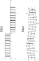
- Fig. 1 illustrates the modulating signal of a PWM H3 signal for a phase of a power converter and its components
- Fig. 2 shows the generation of the PWM signal by intersection of the modulating signal and the carrier signals
- Fig. 3 shows the PWM signal thus obtained.
- the modulating signal of the PWM H3 signal marked 1 is derived from the sum of a fundamental sinusoidal signal at the frequency F pwm marked 2 and a third-harmonic signal also of the sinusoidal type at the frequency F pwm /3 marked 3.
- the amplitude selected in this example for the third-harmonic signal is equal to 1/6th of the amplitude of the fundamental signal. However, other amplitudes may also be selected.
- Fig. 2 shows the intersection of the modulating signal 1 with a first sawtooth carrier signal 4a at the frequency F pwm for the positive amplitudes, and with a second sawtooth carrier signal 4b at the frequency F pwm for the negative amplitudes, where the two carrier signals are synchronous.
- Fig. 3 shows the PWM signal resulting from this intersection.
- the control signal PWM H3 has the advantage of an output power of the power converter receiving the PWM signal generated from this modulating signal that is greater than the power of a power converter controlled by a PWM signal according to the prior state of the art.
- Fig. 4 illustrates the modulating signal of a PWM Toggle signal for a phase of a power converter and its components;
- Fig. 5 shows the generation of the PWM signal by intersection of the modulating signal and the carrier signals; and
- Fig. 6 shows the PWM signal thus obtained.
- the modulating signal of the PWM Toggle signal marked 6 is derived from the sum of a sinusoidal signal at the frequency F pwm marked 7 and a square-wave signal at the frequency F pwm marked 8.
- the amplitude of the square-wave signal is 0.5. However, other amplitudes may also be used.
- Fig. 5 shows the intersection of the modulating signal 6 of the PWM Toggle signal with a first sawtooth carrier signal marked 9a at the frequency F pwm for the positive amplitudes, and with a second sawtooth carrier signal 9b, also at the frequency F pwm , for the negative amplitudes, where the two carrier signals are in phase opposition.
- Fig. 6 shows the PWM signal marked 10 resulting from this intersection.
- the object of the invention is a method for controlling at least two three-phase power converters with asynchronous pulse-width modulation, each power converter being capable of delivering three power supply phases, each supply phase of each converter being controlled by an intersection pulse-width modulation control signal resulting from the intersection of a modulating signal and a carrier signal.
- the method comprises a step in which, for each phase of each converter, the characteristics of the signals used to generate the modulating signal and carrier signal of each control signal of each phase of each converter are determined.
- the method further comprises the following steps:
- phase shift is inserted between the carrier signals used to generate the control signals of the converters.
- a pulse-width modulation control signal by intersection is determined resulting from the intersection of a modulating signal and a carrier signal, and the control signals are transmitted to the converters.
- the control signal may be an asynchronous pulse-width modulation control signal derived from the intersection between a modulating signal and a first sawtooth carrier signal for the positive amplitudes of the modulating signal, and a second sawtooth carrier signal for the negative amplitudes of the modulating signal, where the modulating signal is derived from the sum of a fundamental signal and a third-harmonic signal, both of the sinusoidal type.
- the control signal may be an asynchronous pulse-width modulation control signal derived from the intersection between a modulating signal and a first sawtooth carrier signal for the positive amplitudes of the modulating signal, and a second sawtooth carrier signal for the negative amplitudes of the modulating signal, where the modulating signal is derived from the sum of a sinusoidal signal and a square-wave signal, for which a phase shift is additionally inserted between the carrier signal and the square-wave signal for each control signal of each phase of each converter.
- the phase shift between the square-wave signal and carrier signal may be zero for the first phase, equal to p for the second phase and zero for the third phase for each of the converters.
- the phase shift between the square-wave signal and carrier signal may be zero for the first phase, equal to p for the second phase and zero for the third phase, for the first and third converters, and the phase shift between the square-wave signal and the carrier signal may be equal to p for the first phase, zero for the second phase and equal to p for the third phase for the second converter.
- phase shift between the carrier signals used to generate the control signal of the first phase and the second phase control signal may be equal to 2p/3 and the phase shift between the carrier signals used to generate the control signal of the first phase and the control signal of the third phase may be equal to 4p/3.
- phase shift of the carrier signal used to generate the control signal of the first converter and the phase shift of the carrier signal used to generate the control signal of the second converter may be equal to p.
- phase shift of the carrier signal used to generate the control signal of the first converter and the phase shift of the carrier signal used to generate the control signal of the second converter can be equal to 2p/3 and the phase shift of the carrier signal used to generate the control signal of the second converter and the phase shift of the carrier signal used to generate the control signal of the third converter may also be equal to 2p/3.
- the control method according to the invention is an asynchronous three-phase pulse-width modulation (PWM) control method with at least two power converters.
- the control signals thus generated have phase-shifted carrier signals between the phases U, V and W, making it possible to limit the differential harmonics and zero-sequence harmonics.
- a first control signal is an asynchronous PWM three-phase control signal of the H3 type.
- a second control signal is an asynchronous PWM three-phase control signal of the Toggle type.
- the signal processing also benefits from a new, so-called "Balanced" management of the homopolar signal summed with the fundamental signal to obtain the modulating signal. This management differs depending on the number of power converters controlled in parallel.
- the PWM H3 and Toggle control signals are determined for each phase of each power converter. For these signals to allow the generation of their own current, the signals relating to each phase are phase-shifted.
- a phase shift of 2p/3 is inserted between the carrier signals of the adjacent phases (e.g. for a three-phase system U, V, W, the adjacent phases are the U and V phases or the V and W phases or the W and U phases).
- the carrier signal of the U phase is at the frequency F pwm
- the carrier signal of the V phase is at the frequency F pwm phase-shifted by 2p/3
- the carrier signal of the W phase is at the frequency F pwm phase-shifted by 4p/3.
- the square-wave signal allowing the generation of the PWM Toggle signal is phase-shifted relative to the corresponding carrier signal by p for the phase V1, by 0 for the phase W1, by 0 for the phase U2, by p for the phase V2, and by 0 for the phase W.
- phase shift In question depends on the number of converters. For example, it is equal to p for two converters, and is equal to 2p/3 for three converters and 2p/n for n converters.
- phase shift of 2p/3 for the carrier signal of the phase V1 there is a phase shift of 2p/3 for the carrier signal of the phase V1, a phase shift of 4p/3 for the carrier signal of the phase W1, a phase shift of p for the carrier signal of the phase U2, a phase shift of 5p/3 for the carrier signal of the phase V2 and a phase shift of p/3 for the carrier signal of the phase W2.
- This specific phase shift is equal to p for each phase such that the square-wave signal of the phase U of the second converter is in phase opposition with the square-wave signal of the phase U of the first converter.
- a different additional phase shift is used between the carrier signals relating to the first power converter compared to those of the other power converters.
- a phase shift of p/3 is used between the carrier signals of the phases of the second converter and those of the first converter, and a phase shift of 4p/3 is used between the carrier signals of the phases of the third converter and those of the first converter.
- a specific phase shift is used between the square-wave signal and carrier signal which is zero for the first phase, equal to p for the second phase and zero for the third phase for the first and third converters, and a specific phase shift between the square-wave signal and the carrier signal may be equal to p for the first phase, zero for the second phase and equal to p for the third phase for the second converter.
- phase shift of the square-wave signals has the advantage of balancing the zero-sequence components between the phases of the power converters.
- the method for controlling at least two three-phase power converters with asynchronous pulse-width modulation is shown in Fig. 7 .
- a first step 11 for each phase of each converter, we determine the characteristics of the signals used to generate the modulating signal and the carrier signal of each control signal of each phase of each converter, as described in the prior state of the art, in particular for signals of the H3 and Toggle types.
- a phase shift is inserted between the carrier signals used to generate the phase control signals of the converter.
- a phase shift is inserted between the carrier signals used to generate the phase control signals of the converters.
- a pulse-width modulation control signal by intersection is determined resulting from the intersection of a modulating signal and a carrier signal.
- control signals are transmitted to the converters.
Landscapes
- Engineering & Computer Science (AREA)
- Power Engineering (AREA)
- Inverter Devices (AREA)
Abstract
Description
- The technical field of the invention is the conversion of electrical power and, more particularly, the generation of control signals for such power converters.
- Three-phase electrical motors are powered electrically by power converters, also known as inverters, which transform DC voltage, generally originating from an onboard battery, into AC voltage for each phase of the motor.
- In other cases, the power converters modify an AC or DC input voltage into an AC or DC output voltage respectively having an increased or decreased voltage.
- In certain applications, a plurality of power converters can be used in parallel to provide increased power.
- In that case, asynchronous control signals can be used with pulse-width modulation. The control signals are termed asynchronous because their frequency does not depend on rotation frequency of the electrical motor supplied by the converters.
- Examples of the prior art of such control signals are Toggle-type control signals or H3-type control signals. Toggle-type control signals allow startup losses to be minimized, while H3-type control signals are optimized for operation of the motors above 40% of their maximum rotational speed.
- According to the prior state of the art, the asynchronous PWM control signals of each phase of the converters are derived from in-phase carrier signals.
- The PWM H3 and Toggle signals are intersecting PWM signals, i.e. PWM signals resulting from the intersection of a modulating signal, representing the desired signal by a carrier signal of the sawtooth signal type.
-
Fig. 1 illustrates the modulating signal of a PWM H3 signal for a phase of a power converter and its components;Fig. 2 shows the generation of the PWM signal by intersection of the modulating signal and the carrier signals; andFig. 3 shows the PWM signal thus obtained. - As shown in
Fig. 1 , the modulating signal of the PWM H3 signal marked 1 is derived from the sum of a fundamental sinusoidal signal at the frequency Fpwm marked 2 and a third-harmonic signal also of the sinusoidal type at the frequency Fpwm/3 marked 3. The amplitude selected in this example for the third-harmonic signal is equal to 1/6th of the amplitude of the fundamental signal. However, other amplitudes may also be selected. -
Fig. 2 shows the intersection of the modulatingsignal 1 with a firstsawtooth carrier signal 4a at the frequency Fpwm for the positive amplitudes, and with a secondsawtooth carrier signal 4b at the frequency Fpwm for the negative amplitudes, where the two carrier signals are synchronous.Fig. 3 shows the PWM signal resulting from this intersection. - The control signal PWM H3 has the advantage of an output power of the power converter receiving the PWM signal generated from this modulating signal that is greater than the power of a power converter controlled by a PWM signal according to the prior state of the art.
-
Fig. 4 illustrates the modulating signal of a PWM Toggle signal for a phase of a power converter and its components;Fig. 5 shows the generation of the PWM signal by intersection of the modulating signal and the carrier signals; andFig. 6 shows the PWM signal thus obtained. - As shown in
Fig. 4 , the modulating signal of the PWM Toggle signal marked 6 is derived from the sum of a sinusoidal signal at the frequency Fpwm marked 7 and a square-wave signal at the frequency Fpwm marked 8. - In the example given, the amplitude of the square-wave signal is 0.5. However, other amplitudes may also be used.
-
Fig. 5 shows the intersection of the modulatingsignal 6 of the PWM Toggle signal with a first sawtooth carrier signal marked 9a at the frequency Fpwm for the positive amplitudes, and with a secondsawtooth carrier signal 9b, also at the frequency Fpwm, for the negative amplitudes, where the two carrier signals are in phase opposition.Fig. 6 shows the PWM signal marked 10 resulting from this intersection. - However, the use of asynchronous control signals to control parallel power converters can generate specific, potentially negative effects such as the appearance of differential harmonics and zero-sequence harmonics.
- In the current state of the art, such effects can be minimized only by using massive inductors and an interphase transformer reactor (ITR). This results in substantially large dimensions and weight of the power conversion system as a whole.
- There is thus a need for more efficient power converter control in order to reduce the size and weight of the inductors and the interphase transformer reactor (ITR).
- The object of the invention is a method for controlling at least two three-phase power converters with asynchronous pulse-width modulation, each power converter being capable of delivering three power supply phases, each supply phase of each converter being controlled by an intersection pulse-width modulation control signal resulting from the intersection of a modulating signal and a carrier signal.
- The method comprises a step in which, for each phase of each converter, the characteristics of the signals used to generate the modulating signal and carrier signal of each control signal of each phase of each converter are determined.
- The method further comprises the following steps:
- For each converter, a phase shift is inserted between the carrier signals used to generate the phase control signals of the converter.
- For each phase, a phase shift is inserted between the carrier signals used to generate the control signals of the converters.
- For each phase of each converter, a pulse-width modulation control signal by intersection is determined resulting from the intersection of a modulating signal and a carrier signal, and
the control signals are transmitted to the converters. - The control signal may be an asynchronous pulse-width modulation control signal derived from the intersection between a modulating signal and a first sawtooth carrier signal for the positive amplitudes of the modulating signal, and a second sawtooth carrier signal for the negative amplitudes of the modulating signal, where the modulating signal is derived from the sum of a fundamental signal and a third-harmonic signal, both of the sinusoidal type.
- The control signal may be an asynchronous pulse-width modulation control signal derived from the intersection between a modulating signal and a first sawtooth carrier signal for the positive amplitudes of the modulating signal, and a second sawtooth carrier signal for the negative amplitudes of the modulating signal, where the modulating signal is derived from the sum of a sinusoidal signal and a square-wave signal, for which a phase shift is additionally inserted between the carrier signal and the square-wave signal for each control signal of each phase of each converter.
- When two converters are controlled, the phase shift between the square-wave signal and carrier signal may be zero for the first phase, equal to p for the second phase and zero for the third phase for each of the converters.
- When three converters are controlled, the phase shift between the square-wave signal and carrier signal may be zero for the first phase, equal to p for the second phase and zero for the third phase, for the first and third converters, and the phase shift between the square-wave signal and the carrier signal may be equal to p for the first phase, zero for the second phase and equal to p for the third phase for the second converter.
- For each converter, the phase shift between the carrier signals used to generate the control signal of the first phase and the second phase control signal may be equal to 2p/3 and the phase shift between the carrier signals used to generate the control signal of the first phase and the control signal of the third phase may be equal to 4p/3.
- When two converters are controlled for each phase, the phase shift of the carrier signal used to generate the control signal of the first converter and the phase shift of the carrier signal used to generate the control signal of the second converter may be equal to p.
- When three converters are controlled for each phase, the phase shift of the carrier signal used to generate the control signal of the first converter and the phase shift of the carrier signal used to generate the control signal of the second converter can be equal to 2p/3 and the phase shift of the carrier signal used to generate the control signal of the second converter and the phase shift of the carrier signal used to generate the control signal of the third converter may also be equal to 2p/3.
- Other objects, characteristics and advantages of the invention will become apparent on reading the following description, given solely by way of a nonlimited example, with reference to the accompanying drawings, in which:
-
Fig. 1 shows a modulating signal of a PWM H3 signal for a phase of a power converter and its components, -
Fig. 2 shows the generation of the PWM signal by intersection of the modulating signal and carrier signals, -
Fig. 3 shows the PWM H3 signal obtained, -
Fig. 4 shows a modulating signal of a PWM Toggle signal for a phase of a power converter and its components, -
Fig. 5 shows the generation of the Toggle signal by intersection of the modulating signal and carrier signals, -
Fig. 6 shows the PWM Toggle signal obtained, and -
Fig. 7 shows the principal steps of a control method according to the invention. - The control method according to the invention is an asynchronous three-phase pulse-width modulation (PWM) control method with at least two power converters. The control signals thus generated have phase-shifted carrier signals between the phases U, V and W, making it possible to limit the differential harmonics and zero-sequence harmonics.
- A first control signal is an asynchronous PWM three-phase control signal of the H3 type. A second control signal is an asynchronous PWM three-phase control signal of the Toggle type.
- In the specific case of the PWM Toggle-type control signal, the signal processing also benefits from a new, so-called "Balanced" management of the homopolar signal summed with the fundamental signal to obtain the modulating signal. This management differs depending on the number of power converters controlled in parallel.
- The PWM H3 and Toggle control signals are determined for each phase of each power converter. For these signals to allow the generation of their own current, the signals relating to each phase are phase-shifted.
- For each phase of a converter, a phase shift of 2p/3 is inserted between the carrier signals of the adjacent phases (e.g. for a three-phase system U, V, W, the adjacent phases are the U and V phases or the V and W phases or the W and U phases).
- In other words, the carrier signal of the U phase is at the frequency Fpwm, the carrier signal of the V phase is at the frequency Fpwm phase-shifted by 2p/3 and the carrier signal of the W phase is at the frequency Fpwm phase-shifted by 4p/3.
- In the case of the Toggle PWM signals, a different modulation of the square-wave signal is inserted with regard to the carrier signal for the second power converter in addition to the modulation used for the first converter.
- In the example defined in the introduction, with two three-phase converters generating three phases (U1, V1, W1) and (U2, V2, W2) respectively, taking the signal PWM Toggle of the phase U1 as a reference, the square-wave signal allowing the generation of the PWM Toggle signal is phase-shifted relative to the corresponding carrier signal by p for the phase V1, by 0 for the phase W1, by 0 for the phase U2, by p for the phase V2, and by 0 for the phase W.
- When a plurality of power converters are controlled in parallel, an additional phase shift of the carrier signals relative to the first power converter is inserted with regard to the phase shifts of the other power converters. The phase shift in question depends on the number of converters. For example, it is equal to p for two converters, and is equal to 2p/3 for three converters and 2p/n for n converters.
- In the example of a system with two three-phase power converters (C1, C2) each generating three phases (U1,V1,W1) and (U2,V2,W2), an additional phase shift of the carrier signals is inserted relative to a second power converter with regard to those of the first power converter equal to p.
- Thus, for a system with two three-phase converters, taking the carrier signal of the phase U1 as a reference, there is a phase shift of 2p/3 for the carrier signal of the phase V1, a phase shift of 4p/3 for the carrier signal of the phase W1, a phase shift of p for the carrier signal of the phase U2, a phase shift of 5p/3 for the carrier signal of the phase V2 and a phase shift of p/3 for the carrier signal of the phase W2.
- In addition, in the case of the PWM Toggle control signal, a specific phase shift is added between the square-wave signal and the corresponding carrier signal used to generate the control signals of the phases of the two power converters.
- This specific phase shift is equal to p for each phase such that the square-wave signal of the phase U of the second converter is in phase opposition with the square-wave signal of the phase U of the first converter.
- For a number of power converters different from that shown above, a different additional phase shift is used between the carrier signals relating to the first power converter compared to those of the other power converters.
- For example, in the case of three power converters for the PWM H3 control signal, a phase shift of p/3 is used between the carrier signals of the phases of the second converter and those of the first converter, and a phase shift of 4p/3 is used between the carrier signals of the phases of the third converter and those of the first converter.
- Still in the case of three power converters, for the PWM Toggle control signal, a specific phase shift is used between the square-wave signal and carrier signal which is zero for the first phase, equal to p for the second phase and zero for the third phase for the first and third converters, and a specific phase shift between the square-wave signal and the carrier signal may be equal to p for the first phase, zero for the second phase and equal to p for the third phase for the second converter.
- Such a phase shift of the square-wave signals has the advantage of balancing the zero-sequence components between the phases of the power converters.
- The method for controlling at least two three-phase power converters with asynchronous pulse-width modulation is shown in
Fig. 7 . - During a
first step 11, for each phase of each converter, we determine the characteristics of the signals used to generate the modulating signal and the carrier signal of each control signal of each phase of each converter, as described in the prior state of the art, in particular for signals of the H3 and Toggle types. - During a
second step 12, for each converter, a phase shift is inserted between the carrier signals used to generate the phase control signals of the converter. - During a
third step 13, for each phase, a phase shift is inserted between the carrier signals used to generate the phase control signals of the converters. - During a
fourth step 14, a pulse-width modulation control signal by intersection is determined resulting from the intersection of a modulating signal and a carrier signal. - During a
fifth step 15, the control signals are transmitted to the converters.
Claims (8)
- A method for controlling at least two three-phase power converters with asynchronous pulse-width modulation, wherein each power converter is capable of delivering three power phases and wherein each power supply phase of each power converter is controlled by a pulse-width modulation control signal by intersection resulting from the intersection of a modulating signal and a carrier signal,
the method comprising the following steps:for each phase of each converter, determining (11) the characteristics of the signals used to generate the modulating signal and carrier signal of each control signal,for each converter, inserting (12) a phase shift between the carrier signals used to generate the phase control signals of the converter,for each phase, inserting (12) a phase shift between the carrier signals used to generate the control signals of the converters,for each phase of each converter, determining (14) a pulse-width modulation control signal by intersection resulting from the intersection of a modulating signal and a carrier signal, andtransmitting (15) the control signals to the converters. - Method according to claim 1, wherein the control signal is an asynchronous pulse-width modulation control signal derived from the intersection between a modulating signal and a first sawtooth carrier signal for the positive amplitudes of the modulating signal, and a second sawtooth carrier signal for the negative amplitudes of the modulating signal, wherein the modulating signal is derived from the sum of a fundamental signal and a third-harmonic signal, both of the sinusoidal type.
- Method according to claim 2, wherein the modulating signal is derived from the sum of a sinusoidal signal and a square-wave signal, and further comprising inserting a phase shift is between the carrier signal and the square-wave signal for each control signal of each phase of each converter.
- Method according to claim 3, wherein, when two converters are controlled, the phase shift between the square-wave signal and carrier signal is zero for the first phase, equal to π for the second phase and zero for the third phase for each of the converters.
- Method according to claim 3, wherein when three converters are controlled, the phase shift between the square-wave signal and carrier signal may be zero for the first phase, equal to π for the second phase and zero for the third phase for the first and third converters, and
the phase shift between the square-wave signal and the carrier signal is equal to π for the first phase, zero for the second phase and equal to π for the third phase for the second converter. - Method according to any of the preceding claims, wherein for each converter, the phase shift between the carrier signals used to generate the control signal of the first phase and the second phase control signal is equal to 2π/3 and the phase shift between the carrier signals used to generate the control signal of the first phase and the control signal of the third phase is equal to 4π/3.
- Method according to any of the preceding claims, wherein when two converters are controlled for each phase, the phase shift of the carrier signal used to generate the control signal of the first converter and the phase shift of the carrier signal used to generate the control signal of the second converter is equal to π.
- Method according to any of claims 1 to 7, wherein when three converters are controlled for each phase, the phase shift of the carrier signal used to generate the control signal of the first converter and the phase shift of the carrier signal used to generate the control signal of the second converter is equal to 2π/3 and the phase shift of the carrier signal used to generate the control signal of the second converter and the phase shift of the carrier signal used to generate the control signal of the third converter is also equal to 2π/3.
Applications Claiming Priority (1)
| Application Number | Priority Date | Filing Date | Title |
|---|---|---|---|
| FR1660726A FR3058590B1 (en) | 2016-11-07 | 2016-11-07 | METHOD FOR CONTROLLING ASYNCHRONOUS IMPULSE WIDTH MODULATION OF AT LEAST TWO THREE PHASE POWER CONVERTERS. |
Publications (2)
| Publication Number | Publication Date |
|---|---|
| EP3319214A1 true EP3319214A1 (en) | 2018-05-09 |
| EP3319214B1 EP3319214B1 (en) | 2021-02-17 |
Family
ID=57909650
Family Applications (1)
| Application Number | Title | Priority Date | Filing Date |
|---|---|---|---|
| EP17197906.5A Active EP3319214B1 (en) | 2016-11-07 | 2017-10-24 | A method for controlling at least two three-phase power converters with asynchronous pulse-width modulation |
Country Status (5)
| Country | Link |
|---|---|
| US (1) | US10476371B2 (en) |
| EP (1) | EP3319214B1 (en) |
| CN (1) | CN108075679B (en) |
| ES (1) | ES2865155T3 (en) |
| FR (1) | FR3058590B1 (en) |
Families Citing this family (2)
| Publication number | Priority date | Publication date | Assignee | Title |
|---|---|---|---|---|
| WO2018137752A1 (en) * | 2017-01-24 | 2018-08-02 | Huawei Technologies Co., Ltd. | Power supply and power supply method with circulation current compensation |
| CN112368900A (en) * | 2018-07-25 | 2021-02-12 | 韦斯特尔电子工业和贸易有限责任公司 | Inverter system and method for operating inverter system |
Citations (1)
| Publication number | Priority date | Publication date | Assignee | Title |
|---|---|---|---|---|
| EP0913918A2 (en) * | 1997-10-30 | 1999-05-06 | General Electric Company | Five level high power motor drive converter and control system |
Family Cites Families (3)
| Publication number | Priority date | Publication date | Assignee | Title |
|---|---|---|---|---|
| US5065303A (en) * | 1990-07-24 | 1991-11-12 | Sundstrand Corporation | Transformer-coupled and phase-shifted inverter |
| JPH08280192A (en) * | 1995-04-07 | 1996-10-22 | Meidensha Corp | Inverter parallel operation method and apparatus |
| CN101895222B (en) * | 2010-06-02 | 2012-06-20 | 黑龙江科技学院 | Multi-carrier wave TPWM modulation method based on reverse-phase cross |
-
2016
- 2016-11-07 FR FR1660726A patent/FR3058590B1/en active Active
-
2017
- 2017-10-24 EP EP17197906.5A patent/EP3319214B1/en active Active
- 2017-10-24 ES ES17197906T patent/ES2865155T3/en active Active
- 2017-11-07 CN CN201711085228.5A patent/CN108075679B/en active Active
- 2017-11-07 US US15/805,645 patent/US10476371B2/en active Active
Patent Citations (1)
| Publication number | Priority date | Publication date | Assignee | Title |
|---|---|---|---|---|
| EP0913918A2 (en) * | 1997-10-30 | 1999-05-06 | General Electric Company | Five level high power motor drive converter and control system |
Non-Patent Citations (3)
| Title |
|---|
| BEECHNER T ET AL: "Harmonic cancellation under interleaved PWM with harmonic injection", POWER ELECTRONICS SPECIALISTS CONFERENCE, 2008. PESC 2008. IEEE, IEEE, PISCATAWAY, NJ, USA, 15 June 2008 (2008-06-15), pages 1515 - 1521, XP031300184, ISBN: 978-1-4244-1667-7 * |
| JEFFREY EWANCHUK ET AL: "A five/nine-level twelve-switch neutral point clamped inverter for high speed electric drives", ENERGY CONVERSION CONGRESS AND EXPOSITION (ECCE), 2010 IEEE, IEEE, PISCATAWAY, NJ, USA, 12 September 2010 (2010-09-12), pages 2333 - 2340, XP031787095, ISBN: 978-1-4244-5286-6 * |
| JONATHAN W KIMBALL ET AL: "Reducing Common-Mode Voltage in Three-Phase Sine-Triangle PWM With Interleaved Carriers", IEEE TRANSACTIONS ON POWER ELECTRONICS, INSTITUTE OF ELECTRICAL AND ELECTRONICS ENGINEERS, USA, vol. 26, no. 8, August 2011 (2011-08-01), pages 2229 - 2236, XP011371137, ISSN: 0885-8993, DOI: 10.1109/TPEL.2010.2092791 * |
Also Published As
| Publication number | Publication date |
|---|---|
| ES2865155T3 (en) | 2021-10-15 |
| CN108075679B (en) | 2021-11-09 |
| EP3319214B1 (en) | 2021-02-17 |
| US20180131264A1 (en) | 2018-05-10 |
| CN108075679A (en) | 2018-05-25 |
| FR3058590A1 (en) | 2018-05-11 |
| FR3058590B1 (en) | 2019-06-21 |
| US10476371B2 (en) | 2019-11-12 |
Similar Documents
| Publication | Publication Date | Title |
|---|---|---|
| Loh et al. | Reduced common-mode modulation strategies for cascaded multilevel inverters | |
| Levi et al. | A space-vector modulation scheme for multilevel open-end winding five-phase drives | |
| EP2491644B1 (en) | System and method for offsetting the input voltage unbalance in multilevel inverters or the like | |
| Jones et al. | Carrier‐based pulse‐width modulation techniques for asymmetrical six‐phase open‐end winding drives | |
| Raushan et al. | Comprehensive analysis of a novel three‐phase multilevel inverter with minimum number of switches | |
| Zhang et al. | Field‐oriented control based on hysteresis band current controller for a permanent magnet synchronous motor driven by a direct matrix converter | |
| CN102195550A (en) | Methods, systems and apparatus for optimization of third harmonic current injection in a multi-phase machine | |
| Zhu et al. | Comparison between current‐based and flux/torque‐based model predictive control methods for open‐end winding induction motor drives | |
| Zhu et al. | Duty cycle‐based three‐level space‐vector pulse‐width modulation with overmodulation and neutral‐point balancing capabilities for three‐phase neutral‐point clamped inverters | |
| Sekhar et al. | Torque ripple reduction PWMs for a single DC source powered dual‐inverter fed open‐end winding induction motor drive | |
| Ebrahimzadeh et al. | Modulation technique for four‐leg voltage source inverter without a look‐up table | |
| Khlifi | Behavior of a dual stator induction machine fed by neutral point clamped multilevel inverter | |
| Chakrabarti et al. | A CB-PWM technique for eliminating CMV in multilevel multiphase VSI | |
| CN111133670A (en) | Controlling a voltage source converter in a DC system | |
| Iffouzar et al. | Behavior analysis of a dual stars induction motor supplied by pwm multilevel inverters | |
| US10476371B2 (en) | Method for controlling at least two three-phase power converters with asynchronous pulse-width modulation | |
| CN101895222A (en) | Multi-carrier wave TPWM modulation method based on reverse-phase cross | |
| CN111313799B (en) | Method for controlling three-phase motor | |
| Mohapatra et al. | The novel algorithm-based hysteresis current control technique (HCCT) to eliminate sub and inter harmonics (SIH) in load current | |
| Alsofyani et al. | Finite set predictive torque control based on sub-divided voltage vectors of PMSM with deadbeat control and discrete space vector modulation | |
| Devi et al. | Novel space vector pulse width modulation technique for 5-Phase voltage source inverter | |
| Jones et al. | Decoupled modulation techniques for a four-level five-phase open-end winding drive | |
| Etxeberria et al. | Operational limits of a three level neutral point clamped converter used for controlling a hybrid energy storage system | |
| El Bourhichi et al. | Indirect vector control of induction motor using a five-level cascaded H-bridge inverter | |
| Mondal | Active and reactive power compensation of data center using multi-level STATCOM inverter |
Legal Events
| Date | Code | Title | Description |
|---|---|---|---|
| PUAI | Public reference made under article 153(3) epc to a published international application that has entered the european phase |
Free format text: ORIGINAL CODE: 0009012 |
|
| STAA | Information on the status of an ep patent application or granted ep patent |
Free format text: STATUS: THE APPLICATION HAS BEEN PUBLISHED |
|
| AK | Designated contracting states |
Kind code of ref document: A1 Designated state(s): AL AT BE BG CH CY CZ DE DK EE ES FI FR GB GR HR HU IE IS IT LI LT LU LV MC MK MT NL NO PL PT RO RS SE SI SK SM TR |
|
| AX | Request for extension of the european patent |
Extension state: BA ME |
|
| STAA | Information on the status of an ep patent application or granted ep patent |
Free format text: STATUS: REQUEST FOR EXAMINATION WAS MADE |
|
| 17P | Request for examination filed |
Effective date: 20181109 |
|
| RBV | Designated contracting states (corrected) |
Designated state(s): AL AT BE BG CH CY CZ DE DK EE ES FI FR GB GR HR HU IE IS IT LI LT LU LV MC MK MT NL NO PL PT RO RS SE SI SK SM TR |
|
| STAA | Information on the status of an ep patent application or granted ep patent |
Free format text: STATUS: EXAMINATION IS IN PROGRESS |
|
| 17Q | First examination report despatched |
Effective date: 20191111 |
|
| GRAP | Despatch of communication of intention to grant a patent |
Free format text: ORIGINAL CODE: EPIDOSNIGR1 |
|
| STAA | Information on the status of an ep patent application or granted ep patent |
Free format text: STATUS: GRANT OF PATENT IS INTENDED |
|
| INTG | Intention to grant announced |
Effective date: 20200928 |
|
| GRAS | Grant fee paid |
Free format text: ORIGINAL CODE: EPIDOSNIGR3 |
|
| GRAA | (expected) grant |
Free format text: ORIGINAL CODE: 0009210 |
|
| STAA | Information on the status of an ep patent application or granted ep patent |
Free format text: STATUS: THE PATENT HAS BEEN GRANTED |
|
| AK | Designated contracting states |
Kind code of ref document: B1 Designated state(s): AL AT BE BG CH CY CZ DE DK EE ES FI FR GB GR HR HU IE IS IT LI LT LU LV MC MK MT NL NO PL PT RO RS SE SI SK SM TR |
|
| REG | Reference to a national code |
Ref country code: GB Ref legal event code: FG4D |
|
| REG | Reference to a national code |
Ref country code: CH Ref legal event code: EP |
|
| REG | Reference to a national code |
Ref country code: DE Ref legal event code: R096 Ref document number: 602017032559 Country of ref document: DE |
|
| REG | Reference to a national code |
Ref country code: AT Ref legal event code: REF Ref document number: 1362801 Country of ref document: AT Kind code of ref document: T Effective date: 20210315 |
|
| REG | Reference to a national code |
Ref country code: IE Ref legal event code: FG4D |
|
| REG | Reference to a national code |
Ref country code: CH Ref legal event code: NV Representative=s name: KIRKER AND CIE S.A., CH |
|
| REG | Reference to a national code |
Ref country code: LT Ref legal event code: MG9D |
|
| REG | Reference to a national code |
Ref country code: NL Ref legal event code: MP Effective date: 20210217 |
|
| PG25 | Lapsed in a contracting state [announced via postgrant information from national office to epo] |
Ref country code: GR Free format text: LAPSE BECAUSE OF FAILURE TO SUBMIT A TRANSLATION OF THE DESCRIPTION OR TO PAY THE FEE WITHIN THE PRESCRIBED TIME-LIMIT Effective date: 20210518 Ref country code: FI Free format text: LAPSE BECAUSE OF FAILURE TO SUBMIT A TRANSLATION OF THE DESCRIPTION OR TO PAY THE FEE WITHIN THE PRESCRIBED TIME-LIMIT Effective date: 20210217 Ref country code: HR Free format text: LAPSE BECAUSE OF FAILURE TO SUBMIT A TRANSLATION OF THE DESCRIPTION OR TO PAY THE FEE WITHIN THE PRESCRIBED TIME-LIMIT Effective date: 20210217 Ref country code: PT Free format text: LAPSE BECAUSE OF FAILURE TO SUBMIT A TRANSLATION OF THE DESCRIPTION OR TO PAY THE FEE WITHIN THE PRESCRIBED TIME-LIMIT Effective date: 20210617 Ref country code: NO Free format text: LAPSE BECAUSE OF FAILURE TO SUBMIT A TRANSLATION OF THE DESCRIPTION OR TO PAY THE FEE WITHIN THE PRESCRIBED TIME-LIMIT Effective date: 20210517 Ref country code: BG Free format text: LAPSE BECAUSE OF FAILURE TO SUBMIT A TRANSLATION OF THE DESCRIPTION OR TO PAY THE FEE WITHIN THE PRESCRIBED TIME-LIMIT Effective date: 20210517 Ref country code: LT Free format text: LAPSE BECAUSE OF FAILURE TO SUBMIT A TRANSLATION OF THE DESCRIPTION OR TO PAY THE FEE WITHIN THE PRESCRIBED TIME-LIMIT Effective date: 20210217 |
|
| REG | Reference to a national code |
Ref country code: AT Ref legal event code: MK05 Ref document number: 1362801 Country of ref document: AT Kind code of ref document: T Effective date: 20210217 |
|
| PG25 | Lapsed in a contracting state [announced via postgrant information from national office to epo] |
Ref country code: SE Free format text: LAPSE BECAUSE OF FAILURE TO SUBMIT A TRANSLATION OF THE DESCRIPTION OR TO PAY THE FEE WITHIN THE PRESCRIBED TIME-LIMIT Effective date: 20210217 Ref country code: RS Free format text: LAPSE BECAUSE OF FAILURE TO SUBMIT A TRANSLATION OF THE DESCRIPTION OR TO PAY THE FEE WITHIN THE PRESCRIBED TIME-LIMIT Effective date: 20210217 Ref country code: NL Free format text: LAPSE BECAUSE OF FAILURE TO SUBMIT A TRANSLATION OF THE DESCRIPTION OR TO PAY THE FEE WITHIN THE PRESCRIBED TIME-LIMIT Effective date: 20210217 Ref country code: PL Free format text: LAPSE BECAUSE OF FAILURE TO SUBMIT A TRANSLATION OF THE DESCRIPTION OR TO PAY THE FEE WITHIN THE PRESCRIBED TIME-LIMIT Effective date: 20210217 Ref country code: LV Free format text: LAPSE BECAUSE OF FAILURE TO SUBMIT A TRANSLATION OF THE DESCRIPTION OR TO PAY THE FEE WITHIN THE PRESCRIBED TIME-LIMIT Effective date: 20210217 |
|
| PG25 | Lapsed in a contracting state [announced via postgrant information from national office to epo] |
Ref country code: IS Free format text: LAPSE BECAUSE OF FAILURE TO SUBMIT A TRANSLATION OF THE DESCRIPTION OR TO PAY THE FEE WITHIN THE PRESCRIBED TIME-LIMIT Effective date: 20210617 |
|
| REG | Reference to a national code |
Ref country code: ES Ref legal event code: FG2A Ref document number: 2865155 Country of ref document: ES Kind code of ref document: T3 Effective date: 20211015 |
|
| PG25 | Lapsed in a contracting state [announced via postgrant information from national office to epo] |
Ref country code: CZ Free format text: LAPSE BECAUSE OF FAILURE TO SUBMIT A TRANSLATION OF THE DESCRIPTION OR TO PAY THE FEE WITHIN THE PRESCRIBED TIME-LIMIT Effective date: 20210217 Ref country code: EE Free format text: LAPSE BECAUSE OF FAILURE TO SUBMIT A TRANSLATION OF THE DESCRIPTION OR TO PAY THE FEE WITHIN THE PRESCRIBED TIME-LIMIT Effective date: 20210217 Ref country code: AT Free format text: LAPSE BECAUSE OF FAILURE TO SUBMIT A TRANSLATION OF THE DESCRIPTION OR TO PAY THE FEE WITHIN THE PRESCRIBED TIME-LIMIT Effective date: 20210217 Ref country code: SM Free format text: LAPSE BECAUSE OF FAILURE TO SUBMIT A TRANSLATION OF THE DESCRIPTION OR TO PAY THE FEE WITHIN THE PRESCRIBED TIME-LIMIT Effective date: 20210217 |
|
| REG | Reference to a national code |
Ref country code: DE Ref legal event code: R097 Ref document number: 602017032559 Country of ref document: DE |
|
| PG25 | Lapsed in a contracting state [announced via postgrant information from national office to epo] |
Ref country code: DK Free format text: LAPSE BECAUSE OF FAILURE TO SUBMIT A TRANSLATION OF THE DESCRIPTION OR TO PAY THE FEE WITHIN THE PRESCRIBED TIME-LIMIT Effective date: 20210217 Ref country code: RO Free format text: LAPSE BECAUSE OF FAILURE TO SUBMIT A TRANSLATION OF THE DESCRIPTION OR TO PAY THE FEE WITHIN THE PRESCRIBED TIME-LIMIT Effective date: 20210217 Ref country code: SK Free format text: LAPSE BECAUSE OF FAILURE TO SUBMIT A TRANSLATION OF THE DESCRIPTION OR TO PAY THE FEE WITHIN THE PRESCRIBED TIME-LIMIT Effective date: 20210217 |
|
| PLBE | No opposition filed within time limit |
Free format text: ORIGINAL CODE: 0009261 |
|
| STAA | Information on the status of an ep patent application or granted ep patent |
Free format text: STATUS: NO OPPOSITION FILED WITHIN TIME LIMIT |
|
| 26N | No opposition filed |
Effective date: 20211118 |
|
| PG25 | Lapsed in a contracting state [announced via postgrant information from national office to epo] |
Ref country code: AL Free format text: LAPSE BECAUSE OF FAILURE TO SUBMIT A TRANSLATION OF THE DESCRIPTION OR TO PAY THE FEE WITHIN THE PRESCRIBED TIME-LIMIT Effective date: 20210217 |
|
| PG25 | Lapsed in a contracting state [announced via postgrant information from national office to epo] |
Ref country code: SI Free format text: LAPSE BECAUSE OF FAILURE TO SUBMIT A TRANSLATION OF THE DESCRIPTION OR TO PAY THE FEE WITHIN THE PRESCRIBED TIME-LIMIT Effective date: 20210217 |
|
| PG25 | Lapsed in a contracting state [announced via postgrant information from national office to epo] |
Ref country code: IS Free format text: LAPSE BECAUSE OF FAILURE TO SUBMIT A TRANSLATION OF THE DESCRIPTION OR TO PAY THE FEE WITHIN THE PRESCRIBED TIME-LIMIT Effective date: 20210617 |
|
| REG | Reference to a national code |
Ref country code: BE Ref legal event code: MM Effective date: 20211031 |
|
| GBPC | Gb: european patent ceased through non-payment of renewal fee |
Effective date: 20211024 |
|
| PG25 | Lapsed in a contracting state [announced via postgrant information from national office to epo] |
Ref country code: MC Free format text: LAPSE BECAUSE OF FAILURE TO SUBMIT A TRANSLATION OF THE DESCRIPTION OR TO PAY THE FEE WITHIN THE PRESCRIBED TIME-LIMIT Effective date: 20210217 |
|
| PG25 | Lapsed in a contracting state [announced via postgrant information from national office to epo] |
Ref country code: LU Free format text: LAPSE BECAUSE OF NON-PAYMENT OF DUE FEES Effective date: 20211024 Ref country code: GB Free format text: LAPSE BECAUSE OF NON-PAYMENT OF DUE FEES Effective date: 20211024 Ref country code: BE Free format text: LAPSE BECAUSE OF NON-PAYMENT OF DUE FEES Effective date: 20211031 |
|
| PG25 | Lapsed in a contracting state [announced via postgrant information from national office to epo] |
Ref country code: IE Free format text: LAPSE BECAUSE OF NON-PAYMENT OF DUE FEES Effective date: 20211024 |
|
| PG25 | Lapsed in a contracting state [announced via postgrant information from national office to epo] |
Ref country code: HU Free format text: LAPSE BECAUSE OF FAILURE TO SUBMIT A TRANSLATION OF THE DESCRIPTION OR TO PAY THE FEE WITHIN THE PRESCRIBED TIME-LIMIT; INVALID AB INITIO Effective date: 20171024 |
|
| PG25 | Lapsed in a contracting state [announced via postgrant information from national office to epo] |
Ref country code: CY Free format text: LAPSE BECAUSE OF FAILURE TO SUBMIT A TRANSLATION OF THE DESCRIPTION OR TO PAY THE FEE WITHIN THE PRESCRIBED TIME-LIMIT Effective date: 20210217 |
|
| PG25 | Lapsed in a contracting state [announced via postgrant information from national office to epo] |
Ref country code: MK Free format text: LAPSE BECAUSE OF FAILURE TO SUBMIT A TRANSLATION OF THE DESCRIPTION OR TO PAY THE FEE WITHIN THE PRESCRIBED TIME-LIMIT Effective date: 20210217 |
|
| PG25 | Lapsed in a contracting state [announced via postgrant information from national office to epo] |
Ref country code: MT Free format text: LAPSE BECAUSE OF FAILURE TO SUBMIT A TRANSLATION OF THE DESCRIPTION OR TO PAY THE FEE WITHIN THE PRESCRIBED TIME-LIMIT Effective date: 20210217 |
|
| PGFP | Annual fee paid to national office [announced via postgrant information from national office to epo] |
Ref country code: IT Payment date: 20250923 Year of fee payment: 9 |
|
| PGFP | Annual fee paid to national office [announced via postgrant information from national office to epo] |
Ref country code: FR Payment date: 20250924 Year of fee payment: 9 |
|
| REG | Reference to a national code |
Ref country code: CH Ref legal event code: U11 Free format text: ST27 STATUS EVENT CODE: U-0-0-U10-U11 (AS PROVIDED BY THE NATIONAL OFFICE) Effective date: 20251101 |
|
| PG25 | Lapsed in a contracting state [announced via postgrant information from national office to epo] |
Ref country code: TR Free format text: LAPSE BECAUSE OF FAILURE TO SUBMIT A TRANSLATION OF THE DESCRIPTION OR TO PAY THE FEE WITHIN THE PRESCRIBED TIME-LIMIT Effective date: 20210217 |
|
| PGFP | Annual fee paid to national office [announced via postgrant information from national office to epo] |
Ref country code: DE Payment date: 20250923 Year of fee payment: 9 |
|
| PGFP | Annual fee paid to national office [announced via postgrant information from national office to epo] |
Ref country code: CH Payment date: 20251101 Year of fee payment: 9 |
|
| PGFP | Annual fee paid to national office [announced via postgrant information from national office to epo] |
Ref country code: ES Payment date: 20251103 Year of fee payment: 9 |