EP3319192A1 - Feed through seals and fittings - Google Patents
Feed through seals and fittings Download PDFInfo
- Publication number
- EP3319192A1 EP3319192A1 EP17200007.7A EP17200007A EP3319192A1 EP 3319192 A1 EP3319192 A1 EP 3319192A1 EP 17200007 A EP17200007 A EP 17200007A EP 3319192 A1 EP3319192 A1 EP 3319192A1
- Authority
- EP
- European Patent Office
- Prior art keywords
- bore
- pass
- fitting
- outer body
- wall
- Prior art date
- Legal status (The legal status is an assumption and is not a legal conclusion. Google has not performed a legal analysis and makes no representation as to the accuracy of the status listed.)
- Withdrawn
Links
- 230000008602 contraction Effects 0.000 claims abstract description 21
- 239000007787 solid Substances 0.000 claims abstract description 11
- 239000000945 filler Substances 0.000 claims description 59
- 239000000463 material Substances 0.000 claims description 42
- 238000004891 communication Methods 0.000 claims description 14
- 239000007791 liquid phase Substances 0.000 claims description 13
- 238000000034 method Methods 0.000 claims description 12
- 238000004519 manufacturing process Methods 0.000 claims description 7
- 239000000565 sealant Substances 0.000 claims description 6
- 229920000642 polymer Polymers 0.000 claims description 5
- 239000000654 additive Substances 0.000 claims description 4
- 230000000996 additive effect Effects 0.000 claims description 4
- 230000007613 environmental effect Effects 0.000 claims description 4
- 238000012545 processing Methods 0.000 claims description 4
- 238000007789 sealing Methods 0.000 claims description 4
- 230000006835 compression Effects 0.000 claims description 2
- 238000007906 compression Methods 0.000 claims description 2
- 230000000712 assembly Effects 0.000 description 11
- 238000000429 assembly Methods 0.000 description 11
- 239000012530 fluid Substances 0.000 description 5
- 239000002131 composite material Substances 0.000 description 3
- 239000002184 metal Substances 0.000 description 3
- 239000003566 sealing material Substances 0.000 description 3
- 239000000919 ceramic Substances 0.000 description 2
- 230000000295 complement effect Effects 0.000 description 2
- 239000004593 Epoxy Substances 0.000 description 1
- 235000015842 Hesperis Nutrition 0.000 description 1
- 235000012633 Iberis amara Nutrition 0.000 description 1
- 238000005520 cutting process Methods 0.000 description 1
- 238000005553 drilling Methods 0.000 description 1
- 235000013305 food Nutrition 0.000 description 1
- 239000002828 fuel tank Substances 0.000 description 1
- 238000010438 heat treatment Methods 0.000 description 1
- 238000003780 insertion Methods 0.000 description 1
- 230000037431 insertion Effects 0.000 description 1
- 239000007769 metal material Substances 0.000 description 1
- 238000012986 modification Methods 0.000 description 1
- 230000004048 modification Effects 0.000 description 1
- 238000009928 pasteurization Methods 0.000 description 1
- 239000004814 polyurethane Substances 0.000 description 1
- 229920002635 polyurethane Polymers 0.000 description 1
- 238000003825 pressing Methods 0.000 description 1
- 239000012812 sealant material Substances 0.000 description 1
- 238000012546 transfer Methods 0.000 description 1
- 230000007704 transition Effects 0.000 description 1
- 238000007740 vapor deposition Methods 0.000 description 1
Images


Classifications
-
- H—ELECTRICITY
- H02—GENERATION; CONVERSION OR DISTRIBUTION OF ELECTRIC POWER
- H02G—INSTALLATION OF ELECTRIC CABLES OR LINES, OR OF COMBINED OPTICAL AND ELECTRIC CABLES OR LINES
- H02G3/00—Installations of electric cables or lines or protective tubing therefor in or on buildings, equivalent structures or vehicles
- H02G3/22—Installations of cables or lines through walls, floors or ceilings, e.g. into buildings
-
- F—MECHANICAL ENGINEERING; LIGHTING; HEATING; WEAPONS; BLASTING
- F16—ENGINEERING ELEMENTS AND UNITS; GENERAL MEASURES FOR PRODUCING AND MAINTAINING EFFECTIVE FUNCTIONING OF MACHINES OR INSTALLATIONS; THERMAL INSULATION IN GENERAL
- F16L—PIPES; JOINTS OR FITTINGS FOR PIPES; SUPPORTS FOR PIPES, CABLES OR PROTECTIVE TUBING; MEANS FOR THERMAL INSULATION IN GENERAL
- F16L5/00—Devices for use where pipes, cables or protective tubing pass through walls or partitions
- F16L5/02—Sealing
- F16L5/10—Sealing by using sealing rings or sleeves only
-
- H—ELECTRICITY
- H02—GENERATION; CONVERSION OR DISTRIBUTION OF ELECTRIC POWER
- H02G—INSTALLATION OF ELECTRIC CABLES OR LINES, OR OF COMBINED OPTICAL AND ELECTRIC CABLES OR LINES
- H02G15/00—Cable fittings
- H02G15/013—Sealing means for cable inlets
Definitions
- the disclosed subject matter relates generally to fittings and seals, and more specifically to fittings and seals with one or more feed-through sections.
- Wire, cable, and tubing feed through fittings are used in various applications, including but not limited to engine, commercial, manufacturing, and industrial applications. Often one or more wires, cables, or tubes need to be fed through a wall, housing, baffle, etc., which separates different environments.
- a feed-through typically performs one or more functions. It can act as a hermetic seal that prevents leakage of gas or fluids through the wall. It can cushion and protect wires, cables, and/or tubes from chaffing and cutting damage. It can provide strain relief.
- the CTE (Coefficient of Thermal Expansion) of flexible sealant materials primarily polymers
- This difference can result in the sealant pulling away from the wall of the bore in the fitting body during or after repeated thermal excursions, allowing unintended ingress or egress from the vessel through the fitting body / bore.
- the invention provides a fitting assembly including a fitting having at least a solid outer body, a pass-through bore, and at least one undercut region.
- the pass-through bore is defined by at least one pass-through bore wall, extending longitudinally through a length of the outer body from a first end to a second end.
- the at least one undercut region is formed into the at least one pass-through bore wall, and includes at least one expansion bearing surface disposed radially outward of at least one contraction bearing surface.
- the invention also provides a method including supporting a fitting in a fixture and inserting a filler plug into a first end of a pass-through bore in a fitting.
- An elongated structure is inserted through the pass-through bore and the filler plug.
- a liquid-phase filler material is introduced into a second end of the outer body.
- the liquid-phase filler material substantially fills the pass-through bore and at least one undercut region formed into at least one pass-through bore wall surrounding a portion of the elongated structure in the pass-through bore.
- the liquid-phase filler material is solidified to form a flexible filler material substantially occupying a volume of the pass-through bore and the undercut region, supporting the elongated structure for providing communication between a first volume and a second volume.
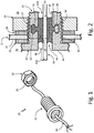
- FIG. 1 is an isometric view of a cable and feed-through fitting assembly for an apparatus.
- Fitting assembly 20 can include a feed-through fitting 22, and one or more fasteners.
- Fitting 22 is shown as, but is not limited to, a threaded screw- or bolt-like member, held against a wall of the apparatus (shown in FIG. 2 ) via complementary nut member 26, and one or more washers or gaskets 28.
- Elongated structure 30, e.g., a wire, cable, or tube provides communication through the wall (shown in FIG. 2 ). Examples of applications include feeding wires from a harsh environment through the wall of an enclosure for sensitive electronic equipment, feeding wires through an oil or fuel tank wall, and feeding wires or tubing through the wall or bulkhead of a pressurized aircraft cabin.
- FIG. 2 shows a cross-sectional view of fitting assembly 20 secured to apparatus 32.
- Apparatus 32 includes at least one wall 34 separating first volume 36 and second volume 38 to be sealed therefrom.
- Wall 34 which can be for example, a housing, bulkhead, baffle, or other includes at least one opening 40 into which at least one fitting assembly 20 is to be installed for passage of elongated structure 30 while maintaining a substantially or completely hermetic seal between first volume 36 and second volume 38.
- Elongated structure 30 can be one or more wires, cables, and/or tubes providing fluid, electrical, and/or signal communication therethrough.
- Apparatus 32 can be any type of equipment, vessel, housing, etc., whereby either multiple internal volumes are to be separated, or whereby an internal volume is to be separated from ambient conditions outside the apparatus while maintaining the above communication via structure 30.
- first and second volumes 36, 38 can operate in a vacuum.
- one of first and second volumes 36, 38 operates in a partial vacuum, while the other operates in a substantially complete vacuum (e.g., less than 10 -5 torr, 1.3mPa). Examples include, but are not limited to, electron microscopes, additive manufacturing equipment, vapor deposition equipment, vacuum furnaces, rockets, satellites, aircraft, spacecraft, etc.
- at least one of first and second volumes 36, 38 operates in a positive-pressure environment (e.g., more than 1 atm, 101kPa).
- first and second volumes 36, 38 have a pressure differential of at least 100 kPa therebetween. Examples include but are not limited to environmental protection enclosures, autoclaves, hot isostatic processing (HIP) furnaces, high pressure food processing (pasteurization) equipment, and equipment for deep sea operations such as submersibles, oil drilling, instrumentation, etc.
- Feed-through fitting 22 is held in place within opening 40, against wall 34 via complementary nut member 26 and one or more washers or gaskets 28.
- Feed-through fitting 22 generally has solid outer body 44, through which pass-through bore 46 is formed. Bore 46 is defined by at least one pass-through bore wall 48, extending longitudinally through a length of outer body 44 from first end 50A to second end 50B.
- At least one undercut region 52 can be formed into an outer wall (e.g., pass-through bore wall 48). Undercut region(s) 52 can include at least one expansion bearing surface 54 disposed radially outward of at least one contraction bearing surface 56.
- Expansion bearing surface(s) 54 and contraction bearing surface(s) 56 can converge at radiused corner(s) 60 to define a dovetail undercut. Radiused corners can reduce stresses from sharp transitions impinging on flexible filler material, which would reduce sealing effectiveness.
- a flexible filler material 58 can substantially occupy a volume of pass-through bore 46 and undercut region(s) 52.
- elongated structure 30 can be a wire, cable, and/or tube supported by filler material 58 and provides fluid, electrical, and/or signal communication between first and second volumes 36, 38.
- Filler material 58 can include, for example, a polymer sealant.
- the filler material has a coefficient of thermal expansion (CTE) of at least 100% more than a CTE of outer body 44, while maintaining a substantially hermetic seal over a temperature range of at least 100° C, or a pressure differential of at least 100 kPa.
- CTE coefficient of thermal expansion
- FIGS. 3A and 3B show a detailed section of FIG. 2 around undercut 52 during thermal excursion of fitting 22 between exposures to relatively hot and cold environments. This can include an overall uniform heating of one or both of first volume 36 and second volume 38 (shown in FIG. 2 ), which may be due to process or environmental changes. It can additionally or alternatively include conductive heat transfer into or out of fitting 22 via wall 34 (also shown in FIG. 2 ).
- FIG. 3A shows expansion of filler material (in direction E) such as during a high temperature excursion.
- the filler material 58 operating as a sealant in pass-through bore 46, tends to expand faster than the metal / ceramic / composite fitting body, thus pressing against pass-through bore wall(s) 48 and expansion bearing surface 54 to form a seal in pass-through bore 44. While filler material 58 tends to pull away at contraction bearing surfaces 56 and corners 60 (see small expansion gaps 64), fluids are mostly or completely unable to escape past sealed bore walls 48 and expansion bearing surface 54.
- filler material 58 contracts (in direction C) relative to the metal / ceramic / composite fitting body such as during a low temperature excursion. As a result, filler material 58 presses against contraction bearing surfaces 56 to form a seal. While filler material 58 tends to pull away at expansion bearing surfaces 54 (see small contraction gaps 66), fluids are unable to escape past contraction bearing surfaces 56 and corners 60.
- the disclosed configurations substantially improve durability and integrity of feed through fittings and seals over previous conventional arrangements.
- the disclosed configurations also can reduce cost, by virtue of enabling use of higher CTE polymer sealing materials such as unfilled epoxy and unfilled polyurethane, which tend to be lower in cost than the more exotic low-CTE sealants currently required to maintain a hermetic seal in fittings without the presently described configurations.
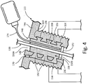
- FIG. 4 shows feed-through fitting 122, which generally has solid outer body 144, through which pass-through bore 146 is formed, defined by at least one pass-through bore wall 148, extending from first end 150A to second end 150B.
- At least one undercut region 152 can be formed into an outer wall (e.g., pass-through bore wall 148). Undercut regions 152 each include expansion bearing surface 154 and contraction bearing surfaces 156 which converge at corner(s) 160, which may or may not be radiused to reduce stresses.
- filler/vent bore 170 in body 144 is substantially parallel and radially offset or outward from pass-through bore 146, and is in communication with at least one undercut region 152.
- One end (here, second end 150B) of pass-through bore 146 can be temporarily plugged, for example, via insertion of filler plug 172 while liquid-phase filler material 158 is introduced into an opposing end (e.g., poured into first end 150A through fill tube 174).
- Fitting body 144 similar to those shown and described in this disclosure, can be supported in a fixture (not currently shown) upright or at a slight angle. Air is thus allowed to escape from bore 170 to minimize bubbles and gaps in the liquid-phase filler material 158 as it substantially fills pass-through bore 146 and the at least one undercut region 152.
- Liquid-phase filler material 158 surrounds a portion of wire / elongated structure 130 extending through a middle portion of pass-through bore 146.
- the liquid-phase filler material 158 is solidified to form a flexible filler material substantially occupying at least a partial volume of pass-through bore 146. It will be recognized that in certain embodiments, bore 170 can be used for filling while one end 150A or 150B of pass-through bore 146 operates as a vent.
- a fitting body can be made by any conventional process.
- metal fittings they can be die or investment cast, sintered, and/or machined.
- the fitting outer body can be formed via at least one additive manufacturing process. If needed or desired, at least one bore wall can be processed to provide a smooth surface.
- the fitting geometry can also be a compression fitting, an interference fitting, or other known or inventive fitting geometry.
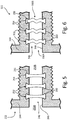
- the pass-through bore shown herein has a substantially constant cross-sectional shape along a length of the outer body, this is not a requirement either. Rather the cross-sectional shape of the pass-through bore geometry, independent from the geometry of undercut(s), can be tapered and/or curved between first and second ends. Examples follow in subsequent figures. Filler material, elongated structures (i.e., wires, tubes, etc.), and optional vent bores are omitted for clarity from FIGS. 5-7 .
- FIG. 5 shows feed-through fitting 222, which generally has solid outer body 244, through which pass-through bore 246 is formed, defined by at least one pass-through bore wall 248, extending from first end 250A to second end 250B.
- Multiple undercut regions 252 are formed into an outer wall (e.g., pass-through bore wall 248) and spaced longitudinally apart from one another. Undercut regions 252 each include expansion bearing surface 254 and contraction bearing surfaces 256 which converge at radiused corner(s) 260 to reduce stresses on flexible filler material (not shown in FIG. 5 ).
- a shape of the undercut portion includes a non-planar (sine wave, herringbone, etc.) path.
- FIG. 6 shows one such example of feed-through fitting 322, which generally has solid outer body 344, through which pass-through bore 346 is formed, defined by at least one pass-through bore wall 348, extending from first end 350A to second end 350B.
- Multiple undercut regions 352, spaced longitudinally apart from one another, can be formed into an outer wall (e.g., pass-through bore wall 348).
- a shape of the undercut portion includes a helical path.
- FIG. 7 shows one such example of feed-through fitting 422, which generally has solid outer body 444, through which pass-through bore 446 is formed, defined by at least one pass-through bore wall 448, extending from first end 450A to second end 450B.
- At least one helical undercut region 452 can be formed into an outer wall (e.g., pass-through bore wall 448).
- Helical undercut region(s) 452 include expansion bearing surface(s) 454 and contraction bearing surface(s) 456 which converge at radiused corner(s) 460 to reduce stresses on flexible filler material (not shown in FIG. 7 ).
- FIG. 7 shows helical undercut groove 452 having at least one of a radial ramp up and a ramp down feature along a length of bore 446
- helical undercut groove(s) can instead have constant (radial) depth from start to finish (see other embodiments).
- a width / radial dimension (excluding undercut 452) of bore 446 varies (via tapering of wall 448) between first and second ends 450A, 450B.
- An embodiment of a fitting assembly includes a fitting having at least a solid outer body, a pass-through bore, and at least one undercut region.
- the pass-through bore is defined by at least one pass-through bore wall, extending longitudinally through a length of the outer body from a first end to a second end.
- the at least one undercut region is formed into the at least one pass-through bore wall, and includes at least one expansion bearing surface disposed radially outward of at least one contraction bearing surface.
- the assembly of the preceding paragraph can optionally include, additionally and/or alternatively, any one or more of the following features, configurations and/or additional components:
- the vessel of the preceding paragraph can optionally include, additionally and/or alternatively, any one or more of the following features, configurations and/or additional components:
- the method of the preceding paragraph can optionally include, additionally and/or alternatively, any one or more of the following features, configurations, steps, and/or additional components:
Landscapes
- Engineering & Computer Science (AREA)
- Architecture (AREA)
- Civil Engineering (AREA)
- Structural Engineering (AREA)
- General Engineering & Computer Science (AREA)
- Mechanical Engineering (AREA)
- Gasket Seals (AREA)
Abstract
Description
- The disclosed subject matter relates generally to fittings and seals, and more specifically to fittings and seals with one or more feed-through sections.
- Wire, cable, and tubing feed through fittings are used in various applications, including but not limited to engine, commercial, manufacturing, and industrial applications. Often one or more wires, cables, or tubes need to be fed through a wall, housing, baffle, etc., which separates different environments.
- A feed-through typically performs one or more functions. It can act as a hermetic seal that prevents leakage of gas or fluids through the wall. It can cushion and protect wires, cables, and/or tubes from chaffing and cutting damage. It can provide strain relief. However, the CTE (Coefficient of Thermal Expansion) of flexible sealant materials (primarily polymers) is universally much greater than the CTE of metal or composite materials used to construct feed-through fitting bodies. This difference can result in the sealant pulling away from the wall of the bore in the fitting body during or after repeated thermal excursions, allowing unintended ingress or egress from the vessel through the fitting body / bore.
- From a first aspect, the invention provides a fitting assembly including a fitting having at least a solid outer body, a pass-through bore, and at least one undercut region. The pass-through bore is defined by at least one pass-through bore wall, extending longitudinally through a length of the outer body from a first end to a second end. The at least one undercut region is formed into the at least one pass-through bore wall, and includes at least one expansion bearing surface disposed radially outward of at least one contraction bearing surface.
- The invention also provides a method including supporting a fitting in a fixture and inserting a filler plug into a first end of a pass-through bore in a fitting. An elongated structure is inserted through the pass-through bore and the filler plug. A liquid-phase filler material is introduced into a second end of the outer body. The liquid-phase filler material substantially fills the pass-through bore and at least one undercut region formed into at least one pass-through bore wall surrounding a portion of the elongated structure in the pass-through bore. The liquid-phase filler material is solidified to form a flexible filler material substantially occupying a volume of the pass-through bore and the undercut region, supporting the elongated structure for providing communication between a first volume and a second volume.
-
-
FIG. 1 is an isometric view of a cable and feed-through fitting for an apparatus. -
FIG. 2 is a cross-sectional view of a cable and feed-through fitting for an apparatus. -
FIG. 3A is a first enlarged sectional view of a fitting with an undercut groove when the sealing material of the fitting is under thermal expansion relative to the fitting body. -
FIG. 3B is a second enlarged sectional view of the fitting inFIG. 3A when the sealing material of the fitting is under thermal contraction relative to the fitting body. -
FIG. 4 shows an example fitting with an optional filler tube to minimize holes in the cured filler material. -
FIG. 5 is a first alternative fitting body. -
FIG. 6 is a second alternative fitting body. -
FIG. 7 is a third alternative fitting body. -
FIG. 1 is an isometric view of a cable and feed-through fitting assembly for an apparatus. The following is but one exemplary application of the present disclosure. Fittingassembly 20 can include a feed-through fitting 22, and one or more fasteners. Fitting 22 is shown as, but is not limited to, a threaded screw- or bolt-like member, held against a wall of the apparatus (shown inFIG. 2 ) viacomplementary nut member 26, and one or more washers orgaskets 28. Elongatedstructure 30, e.g., a wire, cable, or tube provides communication through the wall (shown inFIG. 2 ). Examples of applications include feeding wires from a harsh environment through the wall of an enclosure for sensitive electronic equipment, feeding wires through an oil or fuel tank wall, and feeding wires or tubing through the wall or bulkhead of a pressurized aircraft cabin. -
FIG. 2 shows a cross-sectional view offitting assembly 20 secured toapparatus 32.Apparatus 32 includes at least onewall 34 separatingfirst volume 36 andsecond volume 38 to be sealed therefrom.Wall 34, which can be for example, a housing, bulkhead, baffle, or other includes at least one opening 40 into which at least onefitting assembly 20 is to be installed for passage ofelongated structure 30 while maintaining a substantially or completely hermetic seal betweenfirst volume 36 andsecond volume 38. Elongatedstructure 30 can be one or more wires, cables, and/or tubes providing fluid, electrical, and/or signal communication therethrough.Apparatus 32 can be any type of equipment, vessel, housing, etc., whereby either multiple internal volumes are to be separated, or whereby an internal volume is to be separated from ambient conditions outside the apparatus while maintaining the above communication viastructure 30. - Depending on the particular application, at least one of first and
second volumes second volumes second volumes second volumes - Feed-through fitting 22 is held in place within opening 40, against
wall 34 viacomplementary nut member 26 and one or more washers orgaskets 28. Feed-through fitting 22 generally has solidouter body 44, through which pass-throughbore 46 is formed. Bore 46 is defined by at least one pass-throughbore wall 48, extending longitudinally through a length ofouter body 44 fromfirst end 50A tosecond end 50B. At least oneundercut region 52 can be formed into an outer wall (e.g., pass-through bore wall 48). Undercut region(s) 52 can include at least oneexpansion bearing surface 54 disposed radially outward of at least onecontraction bearing surface 56. Expansion bearing surface(s) 54 and contraction bearing surface(s) 56 can converge at radiused corner(s) 60 to define a dovetail undercut. Radiused corners can reduce stresses from sharp transitions impinging on flexible filler material, which would reduce sealing effectiveness. - As shown in more detail in subsequent figures, a
flexible filler material 58 can substantially occupy a volume of pass-throughbore 46 and undercut region(s) 52. Depending on the particular application,elongated structure 30 can be a wire, cable, and/or tube supported byfiller material 58 and provides fluid, electrical, and/or signal communication between first andsecond volumes Filler material 58 can include, for example, a polymer sealant. In certain embodiments, the filler material has a coefficient of thermal expansion (CTE) of at least 100% more than a CTE ofouter body 44, while maintaining a substantially hermetic seal over a temperature range of at least 100° C, or a pressure differential of at least 100 kPa. -
FIGS. 3A and 3B show a detailed section ofFIG. 2 around undercut 52 during thermal excursion of fitting 22 between exposures to relatively hot and cold environments. This can include an overall uniform heating of one or both offirst volume 36 and second volume 38 (shown inFIG. 2 ), which may be due to process or environmental changes. It can additionally or alternatively include conductive heat transfer into or out of fitting 22 via wall 34 (also shown inFIG. 2 ). -
FIG. 3A shows expansion of filler material (in direction E) such as during a high temperature excursion. Thefiller material 58, operating as a sealant in pass-throughbore 46, tends to expand faster than the metal / ceramic / composite fitting body, thus pressing against pass-through bore wall(s) 48 andexpansion bearing surface 54 to form a seal in pass-throughbore 44. Whilefiller material 58 tends to pull away at contraction bearing surfaces 56 and corners 60 (see small expansion gaps 64), fluids are mostly or completely unable to escape past sealedbore walls 48 andexpansion bearing surface 54. - In
FIG. 3B ,filler material 58 contracts (in direction C) relative to the metal / ceramic / composite fitting body such as during a low temperature excursion. As a result,filler material 58 presses againstcontraction bearing surfaces 56 to form a seal. Whilefiller material 58 tends to pull away at expansion bearing surfaces 54 (see small contraction gaps 66), fluids are unable to escape past contraction bearing surfaces 56 andcorners 60. - Like any configuration, performance of sealing cannot be fully maintained over an unlimited magnitude and number of thermal excursions. However, the disclosed configurations substantially improve durability and integrity of feed through fittings and seals over previous conventional arrangements. In many cases, the disclosed configurations also can reduce cost, by virtue of enabling use of higher CTE polymer sealing materials such as unfilled epoxy and unfilled polyurethane, which tend to be lower in cost than the more exotic low-CTE sealants currently required to maintain a hermetic seal in fittings without the presently described configurations.
-
FIG. 4 shows feed-throughfitting 122, which generally has solidouter body 144, through which pass-throughbore 146 is formed, defined by at least one pass-throughbore wall 148, extending fromfirst end 150A tosecond end 150B. At least one undercutregion 152 can be formed into an outer wall (e.g., pass-through bore wall 148). Undercutregions 152 each includeexpansion bearing surface 154 andcontraction bearing surfaces 156 which converge at corner(s) 160, which may or may not be radiused to reduce stresses. - With certain configurations, and the relatively high viscosity of certain filler materials, it can be helpful in certain embodiments to provide a filler and/or vent bore 170 to assist in pouring or otherwise filling the pass-through
bore 146 and undercutregions 152 while minimizing bubbles which could negatively affect sealing performance. Here, filler/vent bore 170 inbody 144 is substantially parallel and radially offset or outward from pass-throughbore 146, and is in communication with at least one undercutregion 152. - One end (here,
second end 150B) of pass-throughbore 146 can be temporarily plugged, for example, via insertion offiller plug 172 while liquid-phase filler material 158 is introduced into an opposing end (e.g., poured intofirst end 150A through fill tube 174).Fitting body 144, similar to those shown and described in this disclosure, can be supported in a fixture (not currently shown) upright or at a slight angle. Air is thus allowed to escape frombore 170 to minimize bubbles and gaps in the liquid-phase filler material 158 as it substantially fills pass-throughbore 146 and the at least one undercutregion 152. Liquid-phase filler material 158 surrounds a portion of wire /elongated structure 130 extending through a middle portion of pass-throughbore 146. The liquid-phase filler material 158 is solidified to form a flexible filler material substantially occupying at least a partial volume of pass-throughbore 146. It will be recognized that in certain embodiments, bore 170 can be used for filling while oneend bore 146 operates as a vent. - In certain embodiments, a fitting body can be made by any conventional process. For metal fittings, they can be die or investment cast, sintered, and/or machined. To facilitate complex shapes of the undercuts, and/or to facilitate smaller fittings where conventional processes are impractical, the fitting outer body can be formed via at least one additive manufacturing process. If needed or desired, at least one bore wall can be processed to provide a smooth surface.
- Though shown thus far as a threaded fitting with a single undercut, the fitting geometry can also be a compression fitting, an interference fitting, or other known or inventive fitting geometry. And while the pass-through bore shown herein has a substantially constant cross-sectional shape along a length of the outer body, this is not a requirement either. Rather the cross-sectional shape of the pass-through bore geometry, independent from the geometry of undercut(s), can be tapered and/or curved between first and second ends. Examples follow in subsequent figures. Filler material, elongated structures (i.e., wires, tubes, etc.), and optional vent bores are omitted for clarity from
FIGS. 5-7 . -
FIG. 5 shows feed-throughfitting 222, which generally has solidouter body 244, through which pass-throughbore 246 is formed, defined by at least one pass-throughbore wall 248, extending fromfirst end 250A tosecond end 250B. Multiple undercut regions 252 (here, substantially identical dovetails) are formed into an outer wall (e.g., pass-through bore wall 248) and spaced longitudinally apart from one another. Undercutregions 252 each includeexpansion bearing surface 254 andcontraction bearing surfaces 256 which converge at radiused corner(s) 260 to reduce stresses on flexible filler material (not shown inFIG. 5 ). - In certain embodiments, a shape of the undercut portion includes a non-planar (sine wave, herringbone, etc.) path.
FIG. 6 shows one such example of feed-throughfitting 322, which generally has solidouter body 344, through which pass-throughbore 346 is formed, defined by at least one pass-throughbore wall 348, extending fromfirst end 350A tosecond end 350B. Multipleundercut regions 352, spaced longitudinally apart from one another, can be formed into an outer wall (e.g., pass-through bore wall 348). Undercutregions 352 varying laterally in a sine-wave pattern aroundwall 348, each includeexpansion bearing surfaces 354 andcontraction bearing surfaces 356 which converge at radiused corner(s) 360 to reduce stresses on flexible filler material (not shown inFIG. 6 ). - In certain embodiments, a shape of the undercut portion includes a helical path.
FIG. 7 shows one such example of feed-throughfitting 422, which generally has solidouter body 444, through which pass-throughbore 446 is formed, defined by at least one pass-throughbore wall 448, extending fromfirst end 450A tosecond end 450B. At least one helicalundercut region 452 can be formed into an outer wall (e.g., pass-through bore wall 448). Helical undercut region(s) 452 include expansion bearing surface(s) 454 and contraction bearing surface(s) 456 which converge at radiused corner(s) 460 to reduce stresses on flexible filler material (not shown inFIG. 7 ). - Though
FIG. 7 shows helical undercutgroove 452 having at least one of a radial ramp up and a ramp down feature along a length ofbore 446, helical undercut groove(s) can instead have constant (radial) depth from start to finish (see other embodiments). Similarly, a width / radial dimension (excluding undercut 452) ofbore 446 varies (via tapering of wall 448) between first and second ends 450A, 450B. - An embodiment of a fitting assembly according to an exemplary embodiment of this disclosure, among other possible things, includes a fitting having at least a solid outer body, a pass-through bore, and at least one undercut region. The pass-through bore is defined by at least one pass-through bore wall, extending longitudinally through a length of the outer body from a first end to a second end. The at least one undercut region is formed into the at least one pass-through bore wall, and includes at least one expansion bearing surface disposed radially outward of at least one contraction bearing surface.
- The assembly of the preceding paragraph can optionally include, additionally and/or alternatively, any one or more of the following features, configurations and/or additional components:
- A further embodiment of the foregoing assembly, further comprising a flexible filler material substantially occupying a volume of the pass-through bore and the undercut region.
- A further embodiment of any of the foregoing assemblies, wherein the filler material includes a polymer sealant having a CTE of at least 100% more than a CTE of the outer body, while maintaining a hermetic seal over a temperature range of at least 100° C, or a pressure differential of at least 100 kPa.
- A further embodiment of any of the foregoing assemblies, further comprising at least one elongated structure extending through the pass-through bore and supported by the filler material.
- A further embodiment of any of the foregoing assemblies, wherein the at least one expansion bearing surface and the at least one contraction bearing surface converge at a radiused corner.
- A further embodiment of any of the foregoing assemblies, wherein the at least one expansion bearing surface and at least one contraction bearing surface define at least one dovetail undercut.
- A further embodiment of any of the foregoing assemblies, further comprising a filler bore formed in the body substantially parallel and radially offset from the pass-through bore, the filler bore in communication with the at least one undercut region.
- A further embodiment of any of the foregoing assemblies, wherein the fitting is selected from one of: a threaded fitting, a contraction fitting, and an interference fitting.
- A further embodiment of any of the foregoing assemblies, wherein the pass-through bore has a substantially constant cross-sectional shape along a length of the outer body.
- A further embodiment of any of the foregoing assemblies, wherein a shape of the undercut portion includes a non-planar path or a helical path.
- A further embodiment of any of the foregoing assemblies, wherein the helical path includes at least one helical undercut groove having constant depth from start to finish.
- A further embodiment of any of the foregoing assemblies, wherein the bore or the at least one helical undercut groove has at least one of a ramp up feature and a ramp down feature.
- An embodiment of a vessel according to an exemplary embodiment of this disclosure, among other possible things, includes at least one wall separating a first volume and a second volume to be sealed therefrom; at least one fitting assembly according to any of the foregoing fitting assemblies; and an elongated structure for providing communication through the at least one wall between the first and second volumes.
- The vessel of the preceding paragraph can optionally include, additionally and/or alternatively, any one or more of the following features, configurations and/or additional components:
- A further embodiment of the foregoing vessel, wherein at least one of the first and second volumes operate in a vacuum.
- A further embodiment of any of the foregoing vessels, wherein at least one of the first and second volumes operate with a pressure differential of at least 100 kPa therebetween.
- A further embodiment of any of the foregoing vessels, wherein the vessel is an environmental protection enclosure.
- An embodiment of a method according to an exemplary embodiment of this disclosure, among other possible things, includes supporting a fitting in a fixture, the fitting comprising: a solid outer body; a pass-through bore, defined by at least one pass-through bore wall, extending longitudinally through a length of the outer body from a first end to a second end; and at least one undercut region formed into an outer wall defining the pass-through bore, the at least one undercut region including at least one expansion bearing surface disposed radially outward of at least one contraction bearing surface; inserting a filler plug into the first end of the outer body; inserting an elongated structure through the bore and the filler plug; introducing a liquid-phase filler material into the second end of the outer body, surrounding the elongated structure and substantially filling the pass-through bore; and solidifying the liquid-phase filler material to form a flexible filler material substantially occupying a volume of the pass-through bore and the undercut region, supporting the elongated structure for providing communication between a first volume and a second volume.
- The method of the preceding paragraph can optionally include, additionally and/or alternatively, any one or more of the following features, configurations, steps, and/or additional components:
- A further embodiment of the foregoing method, further comprising manufacturing the fitting outer body via at least one additive manufacturing process.
- A further embodiment of any of the foregoing methods, further comprising processing the at least one bore wall to provide a smooth surface.
- A further embodiment of any of the foregoing methods, wherein liquid-phase filler material is introduced into at least one filler bore formed in the body substantially parallel and radially offset from the pass-through bore, the filler bore in communication with the at least one undercut region.
- While the invention has been described with reference to an exemplary embodiment(s), it will be understood by those skilled in the art that various changes may be made and equivalents may be substituted for elements thereof without departing from the scope of the invention. In addition, many modifications may be made to adapt a particular situation or material to the teachings of the invention without departing from the essential scope thereof. Therefore, it is intended that the invention not be limited to the particular embodiment(s) disclosed, but that the invention will include all embodiments falling within the scope of the appended claims.
Claims (15)
- A fitting assembly (20) comprising a fitting (22; 122; 222; 322; 422) comprising:a solid outer body (44; 144; 244; 344; 444);a pass-through bore (46; 146; 246; 346; 446), defined by at least one pass-through bore wall (48; 148; 248; 348; 448), extending longitudinally through a length of the outer body (44...444) from a first end (50A; 150A; 250A; 350A; 450A) to a second end (50B; 150B; 250B; 350B; 450B); andat least one undercut region (52; 152; 252; 352; 452) formed into the at least one pass-through bore wall (48...448), the at least one undercut region (52...452) including at least one expansion bearing surface (54; 154; 254; 354; 454) disposed radially outward of at least one contraction bearing surface (56; 156; 256; 356; 456).
- The assembly (20) of claim 1, wherein the at least one expansion bearing surface (54...454) and the at least one contraction bearing surface (56...456) converge at a radiused corner (60; 160; 260; 360; 460), and optionally define at least one dovetail undercut (52...452).
- The assembly (20) of claim 1 or 2, further comprising a filler bore (170) formed in the body (144) substantially parallel and radially offset from the pass-through bore (146), the filler bore (170) in communication with the at least one undercut region (152).
- The assembly (20) of any preceding claim, wherein the fitting (22...422) is a threaded fitting, a compression fitting, or an interference fitting.
- The assembly (20) of any preceding claim, wherein the pass-through bore (46...446) has a substantially constant cross-sectional shape along a length of the outer body (44...444).
- The assembly (20) of any preceding claim, wherein a shape of the undercut region (452) includes a non-planar path, or a helical path, optionally wherein the helical path includes at least one helical undercut groove having constant depth from start to finish, further optionally wherein the bore (446) or the at least one helical undercut groove has at least one of a ramp up feature and a ramp down feature.
- The assembly (20) of any preceding claim, further comprising a flexible filler material (58; 158) substantially occupying a volume of the pass-through bore (46...446) and the undercut region (52...452).
- The assembly (20) of claim 7, wherein the filler material (58; 158) includes a polymer sealant having a CTE of at least 100% more than a CTE of the outer body (44...444), while maintaining a hermetic seal over a temperature range of at least 100° C or a pressure differential of at least 100 kPa.
- The assembly (20) of claim 7 or 8, further comprising at least one elongated structure (30; 130) extending through the pass-through bore (46...446) and supported by the filler material (58; 158).
- A vessel comprising:a wall (32) separating a first volume (36) and a second volume (38) to be sealed therefrom;an elongated structure (30) providing communication through the wall (32) between the first and second volumes (36, 38); anda fitting assembly (20) including a fitting (22...422) of any of claims 7 to 9 secured to the wall (32) wherein the flexible filler material (58; 158) retains the elongated structure (30) in the bore (46...446) while sealing the first volume (36) from the second volume (38).
- The vessel of claim 10, wherein at least one of the first and second volumes operate with a pressure differential of at least 100 kPa therebetween, and/or wherein at least one of the first and second volumes (36, 38) operates in a vacuum.
- The vessel of claim 10 or 11, wherein the vessel is an environmental protection enclosure.
- A method comprising:supporting a fitting (22...422) in a fixture, the fitting (22...422) comprising:a solid outer body (44...444);a pass-through bore (46...446), defined by at least one pass-through bore wall (48...448), extending longitudinally through a length of the outer body (44...444) from a first end (50A...450A) to a second end (50B...450B); andat least one undercut region (52...452) formed into the at least one pass-through bore wall (48...448), the at least one undercut region (52...452) including at least one expansion bearing surface (54...454) disposed radially outward of at least one contraction bearing surface (56...456);inserting a filler plug (172) into the first end (50A...450A) of the outer body (44...444);inserting an elongated structure (30) through the bore (46...446) and the filler plug (172);introducing a liquid-phase filler material (158) into the second end (50B...450B) of the outer body (44...444), surrounding the elongated structure (30) and filling at least a portion of the pass-through bore (46...446); andsolidifying the liquid-phase filler material (158) to form a flexible filler material (58) occupying at least part of a volume of the pass-through bore (46...446) and the undercut region (52...452), supporting the elongated structure (30) for providing communication between a first volume (36) and a second volume (38).
- The method of claim 13, and further comprising:manufacturing the fitting outer body (44...444) via at least one additive manufacturing process; and/orprocessing the at least one bore wall (48...448) to provide a smooth surface.
- The method of claim 13 or 14, wherein liquid-phase filler material (158) is introduced into at least one filler bore (170) formed in the body (144) parallel and radially offset from the pass-through bore (146), the filler bore (170) being in communication with the at least one undercut region (152).
Applications Claiming Priority (1)
| Application Number | Priority Date | Filing Date | Title |
|---|---|---|---|
| US15/344,343 US10557573B2 (en) | 2016-11-04 | 2016-11-04 | Feed through seals and fittings |
Publications (1)
| Publication Number | Publication Date |
|---|---|
| EP3319192A1 true EP3319192A1 (en) | 2018-05-09 |
Family
ID=60262789
Family Applications (1)
| Application Number | Title | Priority Date | Filing Date |
|---|---|---|---|
| EP17200007.7A Withdrawn EP3319192A1 (en) | 2016-11-04 | 2017-11-03 | Feed through seals and fittings |
Country Status (2)
| Country | Link |
|---|---|
| US (1) | US10557573B2 (en) |
| EP (1) | EP3319192A1 (en) |
Cited By (3)
| Publication number | Priority date | Publication date | Assignee | Title |
|---|---|---|---|---|
| CN109854818A (en) * | 2019-01-16 | 2019-06-07 | 华中科技大学 | A sealed pipeline elastic penetration vibration isolation device |
| IT201900000034A1 (en) * | 2019-01-03 | 2020-07-03 | Detas S P A | Cable gland assembly for passing and guiding a cable |
| CN112879688A (en) * | 2021-02-05 | 2021-06-01 | 黄红英 | Petroleum pipeline connecting device |
Families Citing this family (10)
| Publication number | Priority date | Publication date | Assignee | Title |
|---|---|---|---|---|
| DE102018105870B4 (en) * | 2018-03-14 | 2021-04-29 | Dipl.-Ing. H. Horstmann Gmbh | Water-repellent grommet |
| DE102018213483A1 (en) * | 2018-08-10 | 2020-02-13 | Icotek Project Gmbh & Co. Kg | grommet |
| US20240047956A1 (en) * | 2018-11-07 | 2024-02-08 | Ls Cable & System Ltd. | Jointing system of power cable |
| US11626716B2 (en) * | 2019-12-20 | 2023-04-11 | Raymond & Lae Engineering, Inc. | Floor grommet |
| JP7077347B2 (en) * | 2020-02-17 | 2022-05-30 | 矢崎総業株式会社 | Grommets and wire harnesses |
| DE102020204526A1 (en) * | 2020-04-08 | 2021-10-14 | Icotek Project Gmbh & Co. Kg | Device for the implementation and strain relief of strands |
| CA3176241A1 (en) | 2020-05-13 | 2021-11-18 | GAF Energy LLC | Electrical cable passthrough |
| US12308140B2 (en) * | 2020-12-30 | 2025-05-20 | Eaton Intelligent Power Limited | Additively manufactured cable gland |
| KR20240052936A (en) * | 2021-08-30 | 2024-04-23 | 허브벨 인코포레이티드 | Adaptive seals for cable glands |
| EP4293846A1 (en) * | 2022-06-13 | 2023-12-20 | NKT HV Cables AB | Cable end sealing arrangement for a cable and method for connecting a metallic sheath of a cable end of the cable to a metallic casing of the cable end sealing arrangement |
Citations (8)
| Publication number | Priority date | Publication date | Assignee | Title |
|---|---|---|---|---|
| GB998128A (en) * | 1962-05-10 | 1965-07-14 | Abboflex Ltd | Improvements in or relating to flexible conduits |
| US3331914A (en) * | 1965-09-24 | 1967-07-18 | M & W Electric Mfg Co Inc | Watertight sealing devices for electrical cables |
| DE10053115C1 (en) * | 2000-10-26 | 2002-04-25 | Daimler Chrysler Ag | Cable gland for bodywork aperture in automobile has elastic sleeve with widened section between 2 spaced cuffs filled with sealing medium enclosing cable bundle |
| GB2407352A (en) * | 2003-10-20 | 2005-04-27 | Nat Coupling Co Inc | Pressure energised metal seal for undersea hydraulic coupling |
| EP1580471A2 (en) * | 2004-03-25 | 2005-09-28 | HL Hutterer & Lechner GmbH | Seal arrangement |
| EP2276040A1 (en) * | 2009-07-15 | 2011-01-19 | ABB Research Ltd. | A device for electric connection, a method for producing such a device, and an electric installation |
| EP2445073A1 (en) * | 2010-10-25 | 2012-04-25 | Aldabra S.r.l. | Electrical connection device using a cable gland and method of manufacturing thereof |
| US20140361493A1 (en) * | 2013-06-11 | 2014-12-11 | Delavan Inc | Sealing device |
Family Cites Families (20)
| Publication number | Priority date | Publication date | Assignee | Title |
|---|---|---|---|---|
| US1110947A (en) * | 1911-01-26 | 1914-09-15 | Henry J Lampert | Insulating-joint and process of making the same. |
| DE3246768C1 (en) * | 1982-12-17 | 1989-01-12 | Daimler-Benz Ag, 7000 Stuttgart | Gas and liquid-tight connection between a plastic body and a metal body embedded therein under pressure by flowing around it with a plasticized plastic mass |
| US5442140A (en) * | 1993-10-05 | 1995-08-15 | Homac Mfg. Company | Conduit and cable sealer |
| FI115665B (en) * | 2002-11-08 | 2005-06-15 | Uponor Innovation Ab | A connecting piece |
| US20040155457A1 (en) * | 2003-02-12 | 2004-08-12 | Maersk Medical A/S | Connecting element comprising a first body and a method for injection moulding a connecting element |
| CA2555464C (en) * | 2003-02-12 | 2011-11-08 | Signe Thorning Mejlhede | A medical connector and a method of injection moulding such a connector |
| NL1023688C2 (en) * | 2003-06-18 | 2004-12-21 | Beele Eng Bv | System for sealing a space between an inner wall of a tubular opening and at least one tube or pipe received at least partially in the opening, the axis of which is substantially parallel to the axis of the opening. |
| DE20310390U1 (en) * | 2003-07-04 | 2004-11-11 | Pt-Poly-Tec Gmbh Vertrieb Und Herstellung Von Dichtungssystemen | Connection seal with ratchet teeth |
| DE102005016340B3 (en) * | 2005-04-09 | 2006-08-10 | Adc Gmbh | Cable feed through device, has cable feed through unit with fir tree shapely arranged lamellae at its outer side and rotation-symmetrically formed, where outer diameter of lamellae narrows in axial direction |
| WO2007028443A1 (en) * | 2005-07-13 | 2007-03-15 | Beele Engineering B.V. | System for sealing a space between an inner wall of a tabular opening and at least one tube or duct at least partly received in the opening |
| ES2394649T3 (en) * | 2006-03-20 | 2013-02-04 | Beele Engineering B.V. | System to dynamically seal a conduit sleeve through which a tube or cable extends |
| ES2328612T3 (en) * | 2006-08-25 | 2009-11-16 | Beele Eng Bv | SYSTEM FOR SEALING DYNAMICLY AT LEAST ONE DRIVING THROUGH WHICH A PIPE OR CABLE IS EXTENDED. |
| US7846573B2 (en) * | 2007-06-01 | 2010-12-07 | Cobasys, Llc | Coolant manifold |
| US7810762B2 (en) * | 2007-08-13 | 2010-10-12 | Sioux Chief Mfg. Co., Inc. | Bi-dimensional folding insulator |
| IT1391194B1 (en) * | 2008-08-06 | 2011-11-18 | Dayco Fluid Technologies Spa | ADDUCTION GROUP FOR A AIR CONDITIONING CIRCUIT WITH A 'T' FITTING |
| FR2937112B1 (en) * | 2008-10-13 | 2010-11-12 | Amphenol Air Lb | DEVICE FOR SEALING A DRIVING LINE, METHOD FOR SEALING A DRIVING THROUGH BELLING AND USE OF SUCH A DEVICE FOR THE SEALED HITCH OF AN AIRCRAFT RESERVOIR |
| ES2392791T3 (en) * | 2010-05-25 | 2012-12-13 | Beele Engineering B.V. | An assembly and a method for providing a sealing system in an opening |
| DE102010045146A1 (en) * | 2010-09-11 | 2012-03-15 | Leoni Bordnetz-Systeme Gmbh | Grommet |
| US9194517B2 (en) | 2012-03-27 | 2015-11-24 | Ags I-Prop, Llc | Tube splicing device |
| EP2703705B1 (en) * | 2012-08-30 | 2017-03-29 | Beele Engineering B.V. | Sealing system for an annular space |
-
2016
- 2016-11-04 US US15/344,343 patent/US10557573B2/en active Active
-
2017
- 2017-11-03 EP EP17200007.7A patent/EP3319192A1/en not_active Withdrawn
Patent Citations (8)
| Publication number | Priority date | Publication date | Assignee | Title |
|---|---|---|---|---|
| GB998128A (en) * | 1962-05-10 | 1965-07-14 | Abboflex Ltd | Improvements in or relating to flexible conduits |
| US3331914A (en) * | 1965-09-24 | 1967-07-18 | M & W Electric Mfg Co Inc | Watertight sealing devices for electrical cables |
| DE10053115C1 (en) * | 2000-10-26 | 2002-04-25 | Daimler Chrysler Ag | Cable gland for bodywork aperture in automobile has elastic sleeve with widened section between 2 spaced cuffs filled with sealing medium enclosing cable bundle |
| GB2407352A (en) * | 2003-10-20 | 2005-04-27 | Nat Coupling Co Inc | Pressure energised metal seal for undersea hydraulic coupling |
| EP1580471A2 (en) * | 2004-03-25 | 2005-09-28 | HL Hutterer & Lechner GmbH | Seal arrangement |
| EP2276040A1 (en) * | 2009-07-15 | 2011-01-19 | ABB Research Ltd. | A device for electric connection, a method for producing such a device, and an electric installation |
| EP2445073A1 (en) * | 2010-10-25 | 2012-04-25 | Aldabra S.r.l. | Electrical connection device using a cable gland and method of manufacturing thereof |
| US20140361493A1 (en) * | 2013-06-11 | 2014-12-11 | Delavan Inc | Sealing device |
Cited By (5)
| Publication number | Priority date | Publication date | Assignee | Title |
|---|---|---|---|---|
| IT201900000034A1 (en) * | 2019-01-03 | 2020-07-03 | Detas S P A | Cable gland assembly for passing and guiding a cable |
| WO2020141382A1 (en) * | 2019-01-03 | 2020-07-09 | Detas S.P.A. | A fairlead assembly for passing and guiding one cable |
| EP3906600A1 (en) * | 2019-01-03 | 2021-11-10 | Detas S.p.A. | A fairlead assembly for passing and guiding one cable |
| CN109854818A (en) * | 2019-01-16 | 2019-06-07 | 华中科技大学 | A sealed pipeline elastic penetration vibration isolation device |
| CN112879688A (en) * | 2021-02-05 | 2021-06-01 | 黄红英 | Petroleum pipeline connecting device |
Also Published As
| Publication number | Publication date |
|---|---|
| US20180128400A1 (en) | 2018-05-10 |
| US10557573B2 (en) | 2020-02-11 |
Similar Documents
| Publication | Publication Date | Title |
|---|---|---|
| US10557573B2 (en) | Feed through seals and fittings | |
| EP2052442B1 (en) | Connector arrangement with penetrator in a submersible electrical assembly | |
| EP3411926B1 (en) | Subsea termination gland, connector front end and connector assembly | |
| US11515663B2 (en) | Electrical connector for oilfield operations | |
| EP2902311B1 (en) | Pressure vessel penetrator isolation device | |
| EP0462998B1 (en) | Mounting head for a resistance-tape level sensor | |
| EP3203588B1 (en) | Method of dry-mating a first connector part and a second connector part and connector assembly | |
| EP3224449B1 (en) | Subsea sensor hub | |
| CN103687395B (en) | Airtight canning | |
| CN107895862A (en) | A kind of hermetically-sealed electrical connector and installation method | |
| EP2586103B1 (en) | Subsea container electrical through connector | |
| US12590650B2 (en) | Feedthrough for applications at high pressure | |
| US7534960B2 (en) | Cable stuffing tube | |
| TWM640001U (en) | Seals and vacuum systems with such seals | |
| US11988527B2 (en) | Protection modules for on-board electronics and interconnection method | |
| RU2064213C1 (en) | Hermetically sealed electric connector | |
| EP3152803B1 (en) | Connector part of a connector unit | |
| WO2023113997A1 (en) | Electrical coupling | |
| EP3002843B1 (en) | High voltage joint | |
| JP2023543551A (en) | Device for airtightly supplying a line through a wall and its manufacturing method | |
| WO2020049296A1 (en) | Non-elastomer seals, vacuum pump systems with such seals and a method of manufacture of such seals | |
| RU2685083C1 (en) | Fiber-optic tight transition | |
| CN222596045U (en) | Self-adaptive plunger gas lift and conveying equipment | |
| AU2014384867A1 (en) | Electrical penetrator assembly | |
| EP3977822B1 (en) | Pressure regulator for x-ray apparatus |
Legal Events
| Date | Code | Title | Description |
|---|---|---|---|
| PUAI | Public reference made under article 153(3) epc to a published international application that has entered the european phase |
Free format text: ORIGINAL CODE: 0009012 |
|
| STAA | Information on the status of an ep patent application or granted ep patent |
Free format text: STATUS: THE APPLICATION HAS BEEN PUBLISHED |
|
| AK | Designated contracting states |
Kind code of ref document: A1 Designated state(s): AL AT BE BG CH CY CZ DE DK EE ES FI FR GB GR HR HU IE IS IT LI LT LU LV MC MK MT NL NO PL PT RO RS SE SI SK SM TR |
|
| AX | Request for extension of the european patent |
Extension state: BA ME |
|
| STAA | Information on the status of an ep patent application or granted ep patent |
Free format text: STATUS: REQUEST FOR EXAMINATION WAS MADE |
|
| STAA | Information on the status of an ep patent application or granted ep patent |
Free format text: STATUS: EXAMINATION IS IN PROGRESS |
|
| 17P | Request for examination filed |
Effective date: 20181109 |
|
| RBV | Designated contracting states (corrected) |
Designated state(s): AL AT BE BG CH CY CZ DE DK EE ES FI FR GB GR HR HU IE IS IT LI LT LU LV MC MK MT NL NO PL PT RO RS SE SI SK SM TR |
|
| 17Q | First examination report despatched |
Effective date: 20181130 |
|
| GRAP | Despatch of communication of intention to grant a patent |
Free format text: ORIGINAL CODE: EPIDOSNIGR1 |
|
| STAA | Information on the status of an ep patent application or granted ep patent |
Free format text: STATUS: GRANT OF PATENT IS INTENDED |
|
| INTG | Intention to grant announced |
Effective date: 20201221 |
|
| RAP1 | Party data changed (applicant data changed or rights of an application transferred) |
Owner name: RAYTHEON TECHNOLOGIES CORPORATION |
|
| STAA | Information on the status of an ep patent application or granted ep patent |
Free format text: STATUS: THE APPLICATION IS DEEMED TO BE WITHDRAWN |
|
| 18D | Application deemed to be withdrawn |
Effective date: 20210501 |