EP3318826A1 - Apparatus for air purification and freshness maintenance, and method for controlling same - Google Patents
Apparatus for air purification and freshness maintenance, and method for controlling same Download PDFInfo
- Publication number
- EP3318826A1 EP3318826A1 EP16818238.4A EP16818238A EP3318826A1 EP 3318826 A1 EP3318826 A1 EP 3318826A1 EP 16818238 A EP16818238 A EP 16818238A EP 3318826 A1 EP3318826 A1 EP 3318826A1
- Authority
- EP
- European Patent Office
- Prior art keywords
- led
- air
- cooling channel
- storage space
- disposed
- Prior art date
- Legal status (The legal status is an assumption and is not a legal conclusion. Google has not performed a legal analysis and makes no representation as to the accuracy of the status listed.)
- Granted
Links
Images


Classifications
-
- A—HUMAN NECESSITIES
- A61—MEDICAL OR VETERINARY SCIENCE; HYGIENE
- A61L—METHODS OR APPARATUS FOR STERILISING MATERIALS OR OBJECTS IN GENERAL; DISINFECTION, STERILISATION OR DEODORISATION OF AIR; CHEMICAL ASPECTS OF BANDAGES, DRESSINGS, ABSORBENT PADS OR SURGICAL ARTICLES; MATERIALS FOR BANDAGES, DRESSINGS, ABSORBENT PADS OR SURGICAL ARTICLES
- A61L9/00—Disinfection, sterilisation or deodorisation of air
- A61L9/16—Disinfection, sterilisation or deodorisation of air using physical phenomena
- A61L9/18—Radiation
- A61L9/20—Ultraviolet radiation
- A61L9/205—Ultraviolet radiation using a photocatalyst or photosensitiser
-
- A—HUMAN NECESSITIES
- A23—FOODS OR FOODSTUFFS; TREATMENT THEREOF, NOT COVERED BY OTHER CLASSES
- A23B—PRESERVATION OF FOODS, FOODSTUFFS OR NON-ALCOHOLIC BEVERAGES; CHEMICAL RIPENING OF FRUIT OR VEGETABLES
- A23B2/00—Preservation of foods or foodstuffs, in general
- A23B2/001—Details of apparatus, e.g. pressure feed valves or for transport, or loading or unloading manipulation
-
- A—HUMAN NECESSITIES
- A23—FOODS OR FOODSTUFFS; TREATMENT THEREOF, NOT COVERED BY OTHER CLASSES
- A23B—PRESERVATION OF FOODS, FOODSTUFFS OR NON-ALCOHOLIC BEVERAGES; CHEMICAL RIPENING OF FRUIT OR VEGETABLES
- A23B2/00—Preservation of foods or foodstuffs, in general
- A23B2/70—Preservation of foods or foodstuffs, in general by treatment with chemicals
- A23B2/704—Preservation of foods or foodstuffs, in general by treatment with chemicals in the form of gases, e.g. fumigation; Compositions or apparatus therefor
- A23B2/708—Preservation of foods or foodstuffs, in general by treatment with chemicals in the form of gases, e.g. fumigation; Compositions or apparatus therefor in a controlled atmosphere, e.g. partial vacuum, comprising only CO2, N2, O2 or H2O
-
- A—HUMAN NECESSITIES
- A61—MEDICAL OR VETERINARY SCIENCE; HYGIENE
- A61L—METHODS OR APPARATUS FOR STERILISING MATERIALS OR OBJECTS IN GENERAL; DISINFECTION, STERILISATION OR DEODORISATION OF AIR; CHEMICAL ASPECTS OF BANDAGES, DRESSINGS, ABSORBENT PADS OR SURGICAL ARTICLES; MATERIALS FOR BANDAGES, DRESSINGS, ABSORBENT PADS OR SURGICAL ARTICLES
- A61L9/00—Disinfection, sterilisation or deodorisation of air
- A61L9/16—Disinfection, sterilisation or deodorisation of air using physical phenomena
- A61L9/18—Radiation
- A61L9/20—Ultraviolet radiation
-
- B—PERFORMING OPERATIONS; TRANSPORTING
- B01—PHYSICAL OR CHEMICAL PROCESSES OR APPARATUS IN GENERAL
- B01D—SEPARATION
- B01D46/00—Filters or filtering processes specially modified for separating dispersed particles from gases or vapours
-
- B—PERFORMING OPERATIONS; TRANSPORTING
- B01—PHYSICAL OR CHEMICAL PROCESSES OR APPARATUS IN GENERAL
- B01D—SEPARATION
- B01D53/00—Separation of gases or vapours; Recovering vapours of volatile solvents from gases; Chemical or biological purification of waste gases, e.g. engine exhaust gases, smoke, fumes, flue gases, aerosols
- B01D53/34—Chemical or biological purification of waste gases
- B01D53/74—General processes for purification of waste gases; Apparatus or devices specially adapted therefor
- B01D53/86—Catalytic processes
-
- B—PERFORMING OPERATIONS; TRANSPORTING
- B01—PHYSICAL OR CHEMICAL PROCESSES OR APPARATUS IN GENERAL
- B01D—SEPARATION
- B01D53/00—Separation of gases or vapours; Recovering vapours of volatile solvents from gases; Chemical or biological purification of waste gases, e.g. engine exhaust gases, smoke, fumes, flue gases, aerosols
- B01D53/34—Chemical or biological purification of waste gases
- B01D53/74—General processes for purification of waste gases; Apparatus or devices specially adapted therefor
- B01D53/86—Catalytic processes
- B01D53/8668—Removing organic compounds not provided for in B01D53/8603 - B01D53/8665
-
- B—PERFORMING OPERATIONS; TRANSPORTING
- B01—PHYSICAL OR CHEMICAL PROCESSES OR APPARATUS IN GENERAL
- B01D—SEPARATION
- B01D53/00—Separation of gases or vapours; Recovering vapours of volatile solvents from gases; Chemical or biological purification of waste gases, e.g. engine exhaust gases, smoke, fumes, flue gases, aerosols
- B01D53/34—Chemical or biological purification of waste gases
- B01D53/74—General processes for purification of waste gases; Apparatus or devices specially adapted therefor
- B01D53/86—Catalytic processes
- B01D53/88—Handling or mounting catalysts
- B01D53/885—Devices in general for catalytic purification of waste gases
-
- F—MECHANICAL ENGINEERING; LIGHTING; HEATING; WEAPONS; BLASTING
- F25—REFRIGERATION OR COOLING; COMBINED HEATING AND REFRIGERATION SYSTEMS; HEAT PUMP SYSTEMS; MANUFACTURE OR STORAGE OF ICE; LIQUEFACTION SOLIDIFICATION OF GASES
- F25D—REFRIGERATORS; COLD ROOMS; ICE-BOXES; COOLING OR FREEZING APPARATUS NOT OTHERWISE PROVIDED FOR
- F25D17/00—Arrangements for circulating cooling fluids; Arrangements for circulating gas, e.g. air, within refrigerated spaces
- F25D17/04—Arrangements for circulating cooling fluids; Arrangements for circulating gas, e.g. air, within refrigerated spaces for circulating air, e.g. by convection
-
- F—MECHANICAL ENGINEERING; LIGHTING; HEATING; WEAPONS; BLASTING
- F25—REFRIGERATION OR COOLING; COMBINED HEATING AND REFRIGERATION SYSTEMS; HEAT PUMP SYSTEMS; MANUFACTURE OR STORAGE OF ICE; LIQUEFACTION SOLIDIFICATION OF GASES
- F25D—REFRIGERATORS; COLD ROOMS; ICE-BOXES; COOLING OR FREEZING APPARATUS NOT OTHERWISE PROVIDED FOR
- F25D17/00—Arrangements for circulating cooling fluids; Arrangements for circulating gas, e.g. air, within refrigerated spaces
- F25D17/04—Arrangements for circulating cooling fluids; Arrangements for circulating gas, e.g. air, within refrigerated spaces for circulating air, e.g. by convection
- F25D17/042—Air treating means within refrigerated spaces
-
- F—MECHANICAL ENGINEERING; LIGHTING; HEATING; WEAPONS; BLASTING
- F25—REFRIGERATION OR COOLING; COMBINED HEATING AND REFRIGERATION SYSTEMS; HEAT PUMP SYSTEMS; MANUFACTURE OR STORAGE OF ICE; LIQUEFACTION SOLIDIFICATION OF GASES
- F25D—REFRIGERATORS; COLD ROOMS; ICE-BOXES; COOLING OR FREEZING APPARATUS NOT OTHERWISE PROVIDED FOR
- F25D17/00—Arrangements for circulating cooling fluids; Arrangements for circulating gas, e.g. air, within refrigerated spaces
- F25D17/04—Arrangements for circulating cooling fluids; Arrangements for circulating gas, e.g. air, within refrigerated spaces for circulating air, e.g. by convection
- F25D17/06—Arrangements for circulating cooling fluids; Arrangements for circulating gas, e.g. air, within refrigerated spaces for circulating air, e.g. by convection by forced circulation
-
- F—MECHANICAL ENGINEERING; LIGHTING; HEATING; WEAPONS; BLASTING
- F25—REFRIGERATION OR COOLING; COMBINED HEATING AND REFRIGERATION SYSTEMS; HEAT PUMP SYSTEMS; MANUFACTURE OR STORAGE OF ICE; LIQUEFACTION SOLIDIFICATION OF GASES
- F25D—REFRIGERATORS; COLD ROOMS; ICE-BOXES; COOLING OR FREEZING APPARATUS NOT OTHERWISE PROVIDED FOR
- F25D23/00—General constructional features
-
- F—MECHANICAL ENGINEERING; LIGHTING; HEATING; WEAPONS; BLASTING
- F25—REFRIGERATION OR COOLING; COMBINED HEATING AND REFRIGERATION SYSTEMS; HEAT PUMP SYSTEMS; MANUFACTURE OR STORAGE OF ICE; LIQUEFACTION SOLIDIFICATION OF GASES
- F25D—REFRIGERATORS; COLD ROOMS; ICE-BOXES; COOLING OR FREEZING APPARATUS NOT OTHERWISE PROVIDED FOR
- F25D29/00—Arrangement or mounting of control or safety devices
-
- A—HUMAN NECESSITIES
- A23—FOODS OR FOODSTUFFS; TREATMENT THEREOF, NOT COVERED BY OTHER CLASSES
- A23V—INDEXING SCHEME RELATING TO FOODS, FOODSTUFFS OR NON-ALCOHOLIC BEVERAGES AND LACTIC OR PROPIONIC ACID BACTERIA USED IN FOODSTUFFS OR FOOD PREPARATION
- A23V2002/00—Food compositions, function of food ingredients or processes for food or foodstuffs
-
- A—HUMAN NECESSITIES
- A61—MEDICAL OR VETERINARY SCIENCE; HYGIENE
- A61L—METHODS OR APPARATUS FOR STERILISING MATERIALS OR OBJECTS IN GENERAL; DISINFECTION, STERILISATION OR DEODORISATION OF AIR; CHEMICAL ASPECTS OF BANDAGES, DRESSINGS, ABSORBENT PADS OR SURGICAL ARTICLES; MATERIALS FOR BANDAGES, DRESSINGS, ABSORBENT PADS OR SURGICAL ARTICLES
- A61L2209/00—Aspects relating to disinfection, sterilisation or deodorisation of air
- A61L2209/10—Apparatus features
- A61L2209/11—Apparatus for controlling air treatment
- A61L2209/111—Sensor means, e.g. motion, brightness, scent, contaminant sensors
-
- A—HUMAN NECESSITIES
- A61—MEDICAL OR VETERINARY SCIENCE; HYGIENE
- A61L—METHODS OR APPARATUS FOR STERILISING MATERIALS OR OBJECTS IN GENERAL; DISINFECTION, STERILISATION OR DEODORISATION OF AIR; CHEMICAL ASPECTS OF BANDAGES, DRESSINGS, ABSORBENT PADS OR SURGICAL ARTICLES; MATERIALS FOR BANDAGES, DRESSINGS, ABSORBENT PADS OR SURGICAL ARTICLES
- A61L2209/00—Aspects relating to disinfection, sterilisation or deodorisation of air
- A61L2209/10—Apparatus features
- A61L2209/12—Lighting means
-
- A—HUMAN NECESSITIES
- A61—MEDICAL OR VETERINARY SCIENCE; HYGIENE
- A61L—METHODS OR APPARATUS FOR STERILISING MATERIALS OR OBJECTS IN GENERAL; DISINFECTION, STERILISATION OR DEODORISATION OF AIR; CHEMICAL ASPECTS OF BANDAGES, DRESSINGS, ABSORBENT PADS OR SURGICAL ARTICLES; MATERIALS FOR BANDAGES, DRESSINGS, ABSORBENT PADS OR SURGICAL ARTICLES
- A61L2209/00—Aspects relating to disinfection, sterilisation or deodorisation of air
- A61L2209/10—Apparatus features
- A61L2209/14—Filtering means
-
- B—PERFORMING OPERATIONS; TRANSPORTING
- B01—PHYSICAL OR CHEMICAL PROCESSES OR APPARATUS IN GENERAL
- B01D—SEPARATION
- B01D2255/00—Catalysts
- B01D2255/80—Type of catalytic reaction
- B01D2255/802—Photocatalytic
-
- B—PERFORMING OPERATIONS; TRANSPORTING
- B01—PHYSICAL OR CHEMICAL PROCESSES OR APPARATUS IN GENERAL
- B01D—SEPARATION
- B01D2257/00—Components to be removed
- B01D2257/70—Organic compounds not provided for in groups B01D2257/00 - B01D2257/602
- B01D2257/708—Volatile organic compounds V.O.C.'s
-
- B—PERFORMING OPERATIONS; TRANSPORTING
- B01—PHYSICAL OR CHEMICAL PROCESSES OR APPARATUS IN GENERAL
- B01D—SEPARATION
- B01D2257/00—Components to be removed
- B01D2257/90—Odorous compounds not provided for in groups B01D2257/00 - B01D2257/708
-
- B—PERFORMING OPERATIONS; TRANSPORTING
- B01—PHYSICAL OR CHEMICAL PROCESSES OR APPARATUS IN GENERAL
- B01D—SEPARATION
- B01D2257/00—Components to be removed
- B01D2257/91—Bacteria; Microorganisms
-
- B—PERFORMING OPERATIONS; TRANSPORTING
- B01—PHYSICAL OR CHEMICAL PROCESSES OR APPARATUS IN GENERAL
- B01D—SEPARATION
- B01D2258/00—Sources of waste gases
- B01D2258/06—Polluted air
-
- B—PERFORMING OPERATIONS; TRANSPORTING
- B01—PHYSICAL OR CHEMICAL PROCESSES OR APPARATUS IN GENERAL
- B01D—SEPARATION
- B01D2259/00—Type of treatment
- B01D2259/80—Employing electric, magnetic, electromagnetic or wave energy, or particle radiation
- B01D2259/804—UV light
-
- F—MECHANICAL ENGINEERING; LIGHTING; HEATING; WEAPONS; BLASTING
- F25—REFRIGERATION OR COOLING; COMBINED HEATING AND REFRIGERATION SYSTEMS; HEAT PUMP SYSTEMS; MANUFACTURE OR STORAGE OF ICE; LIQUEFACTION SOLIDIFICATION OF GASES
- F25D—REFRIGERATORS; COLD ROOMS; ICE-BOXES; COOLING OR FREEZING APPARATUS NOT OTHERWISE PROVIDED FOR
- F25D2317/00—Details or arrangements for circulating cooling fluids; Details or arrangements for circulating gas, e.g. air, within refrigerated spaces, not provided for in other groups of this subclass
- F25D2317/04—Treating air flowing to refrigeration compartments
- F25D2317/041—Treating air flowing to refrigeration compartments by purification
- F25D2317/0417—Treating air flowing to refrigeration compartments by purification using an UV-lamp
-
- F—MECHANICAL ENGINEERING; LIGHTING; HEATING; WEAPONS; BLASTING
- F25—REFRIGERATION OR COOLING; COMBINED HEATING AND REFRIGERATION SYSTEMS; HEAT PUMP SYSTEMS; MANUFACTURE OR STORAGE OF ICE; LIQUEFACTION SOLIDIFICATION OF GASES
- F25D—REFRIGERATORS; COLD ROOMS; ICE-BOXES; COOLING OR FREEZING APPARATUS NOT OTHERWISE PROVIDED FOR
- F25D2317/00—Details or arrangements for circulating cooling fluids; Details or arrangements for circulating gas, e.g. air, within refrigerated spaces, not provided for in other groups of this subclass
- F25D2317/06—Details or arrangements for circulating cooling fluids; Details or arrangements for circulating gas, e.g. air, within refrigerated spaces, not provided for in other groups of this subclass with forced air circulation
- F25D2317/065—Details or arrangements for circulating cooling fluids; Details or arrangements for circulating gas, e.g. air, within refrigerated spaces, not provided for in other groups of this subclass with forced air circulation characterised by the air return
- F25D2317/0655—Details or arrangements for circulating cooling fluids; Details or arrangements for circulating gas, e.g. air, within refrigerated spaces, not provided for in other groups of this subclass with forced air circulation characterised by the air return through the top
-
- F—MECHANICAL ENGINEERING; LIGHTING; HEATING; WEAPONS; BLASTING
- F25—REFRIGERATION OR COOLING; COMBINED HEATING AND REFRIGERATION SYSTEMS; HEAT PUMP SYSTEMS; MANUFACTURE OR STORAGE OF ICE; LIQUEFACTION SOLIDIFICATION OF GASES
- F25D—REFRIGERATORS; COLD ROOMS; ICE-BOXES; COOLING OR FREEZING APPARATUS NOT OTHERWISE PROVIDED FOR
- F25D2317/00—Details or arrangements for circulating cooling fluids; Details or arrangements for circulating gas, e.g. air, within refrigerated spaces, not provided for in other groups of this subclass
- F25D2317/06—Details or arrangements for circulating cooling fluids; Details or arrangements for circulating gas, e.g. air, within refrigerated spaces, not provided for in other groups of this subclass with forced air circulation
- F25D2317/066—Details or arrangements for circulating cooling fluids; Details or arrangements for circulating gas, e.g. air, within refrigerated spaces, not provided for in other groups of this subclass with forced air circulation characterised by the air supply
- F25D2317/0661—Details or arrangements for circulating cooling fluids; Details or arrangements for circulating gas, e.g. air, within refrigerated spaces, not provided for in other groups of this subclass with forced air circulation characterised by the air supply from the bottom
-
- F—MECHANICAL ENGINEERING; LIGHTING; HEATING; WEAPONS; BLASTING
- F25—REFRIGERATION OR COOLING; COMBINED HEATING AND REFRIGERATION SYSTEMS; HEAT PUMP SYSTEMS; MANUFACTURE OR STORAGE OF ICE; LIQUEFACTION SOLIDIFICATION OF GASES
- F25D—REFRIGERATORS; COLD ROOMS; ICE-BOXES; COOLING OR FREEZING APPARATUS NOT OTHERWISE PROVIDED FOR
- F25D2700/00—Means for sensing or measuring; Sensors therefor
- F25D2700/02—Sensors detecting door opening
Definitions
- the present invention relates to an apparatus for air purification and freshness preservation and a method for controlling the same, and, more particularly, to an apparatus which can purify air inside a refrigerator and preserve freshness with minimized modification to an existing refrigerator structure.
- Air in a food storage space of a refrigerator or the like is mixed with odors of foods, causing discomfort to a user.
- a deodorant containing activated carbon capable of adsorbing such odors is currently being developed and sold.
- Such a deodorant is used in a refrigerator for a certain period of time and then discarded.
- the deodorant is used as a disposable product and thus has problems such as difficulty in recycling and a need for continuous replacement.
- a photocatalytic filter decomposing and deodorizing harmful gases in air using a photocatalyst material activated by UV light is recyclable and thus can be used semi-permanently.
- the photocatalytic filter and the light source need to be designed to maximize air purification efficiency while being as compact as possible. Therefore, in design of the photocatalytic filter and the light source, air flow path, air suction and discharge directions, filter structure, relationship between filter installation direction and air flow direction, and light source installation position need to be considered.
- the odor of foods is not the only problem with using a refrigerator.
- the fruits or the vegetables are likely to quickly soften due to ethylene emitted therefrom. If a door of the refrigerator is frequently opened to remove ethylene from air inside the refrigerator, refrigeration efficiency can be deteriorated. Further, ethylene is not adsorbed well onto a deodorant.
- floating microorganisms or bacteria can be densely present in a confined space in the refrigerator in which foods are stored.
- a deodorant cannot destroy such microorganisms or bacteria.
- refrigerated foods spoil or rot due to the bacteria or microorganisms, there is a risk of stomach ache or food poisoning.
- harmful gases e.g. petroleum-based aromatic compounds
- a synthetic resin of an inner wall of a new refrigerator are likely to remain in a sealed space in the refrigerator for several years.
- Embodiments of the present invention have been conceived to solve such a problem in the art, and one aspect of the present invention is to provide a purification apparatus which can provide both deodorization of an internal space of a refrigerator and preservation of freshness of vegetables or fruits using a photocatalytic filter and a light source with minimized modification to an existing refrigerator structure, while providing both sterilization and removal of harmful gases.
- an apparatus for air purification and freshness preservation which is installed in a cooling channel 14 formed separately from a storage space 12 of a refrigerator 10 and communicating with the storage space 12 through an inlet 13 and an outlet 15, the apparatus including: a photocatalytic filter 30 disposed in the vicinity of the outlet 15 of the cooling channel 14, the photocatalytic filter 30 being formed with a plurality of cells 32 constituting vent holes in an air flow direction in the cooling channel 14; and a UV LED 41 disposed in the cooling channel 14 to emit UV light toward the cells 32 of the photocatalytic filter 30.
- An air discharge direction through the outlet 15 may be substantially perpendicular to a direction in which the vent holes of the photocatalytic filter 30 extend.
- the UV LED 41 may be mounted on a substrate 42 disposed on an inner wall of the cooling channel 14.
- the cooling channel 14 may be provided with a fan 20 forcing air to flow and an evaporator 22 cooling the flowing air, and the photocatalytic filter 30 and the UV LED 41 may be disposed downstream of the evaporator 22 in the cooling channel.
- the evaporator 22 may be disposed opposite the UV LED 41 with the photocatalytic filter 30 interposed therebetween.
- the photocatalytic filter 30 may be obtained by coating a surface of a base 31 with a photocatalytic material, the base having a generally cuboid shape and including a plurality of cells 32 vertically formed therethrough to allow air to pass therethrough.
- an apparatus for air purification and freshness preservation which is installed on a drawer 16 disposed in a storage space 12 of a refrigerator 10 and on an inner wall of the storage space 12 facing the drawer 16, the apparatus including: pores 17 formed through a wall of the drawer 16 to allow air to flow into or out of the drawer; a photocatalyst material disposed on an outer surface of the wall of the drawer with the pores 17 formed therethrough; and a UV LED 41 disposed on the inner wall of the storage space 12 to irradiate the photocatalyst material with UV light.
- the apparatus may further include: a light guide plate 45 disposed on the inner wall of the storage space 12 facing the wall of the drawer with the pores 17 formed therethrough to direct light from the UV LED toward the photocatalyst material disposed on the outer surface of the wall of the drawer, wherein the UV LED 41 may emit UV light toward the light guide plate 45.
- a method for controlling the apparatus for air purification and freshness preservation including: detecting whether a door of the refrigerator 10 is open; and shutting off power supply to the UV LED 41 when the door of the refrigerator is detected to be open.
- the method may further include: turning on the UV LED 41 when the door is closed again after being detected to be open and turning off the UV LED 41 when a predetermined period of time elapses.
- the fan 20 disposed in the cooling channel 14 may be operated while the UV LED 41 is turned on.
- the method may further include: measuring a concentration of ethylene in air in the storage space; and turning on the UV LED 41 when the measured concentration of ethylene exceeds a reference value and turning off the UV LED 41 when a predetermined period of time elapses.
- the fan 20 disposed in the cooling channel 14 may be operated while the UV LED 41 is turned on.
- the method may further include: operating the evaporator 22 and the fan 20 in the cooling channel 14 when an internal temperature of the storage space rises above a reference value; and turning on the UV LED 41 while the fan 20 is operated.
- the method may further include: turning off the UV LED 41 when a predetermined period of time elapses after the fan 20 is operated.
- air inside a refrigerator can be semi-permanently purified and kept fresh very quickly and efficiently with minimized modification to an existing refrigerator structure.
- photocatalytic reaction efficiency can be greatly increased in a narrow space.
- air inside a refrigerator can be purified very efficiently.
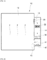
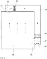
- FIGS. 1 and 2 are schematic views of a refrigerator using an apparatus for air purification and freshness preservation according to a first embodiment of the present invention
- FIGS. 3 and 4 are a perspective view and plan view of a photocatalytic filter used in the apparatus for air purification and freshness preservation according to the first embodiment, respectively.
- the apparatus for air purification and freshness preservation according to the present invention is installed in a refrigerator 10, as shown in the drawings.
- the refrigerator 10 includes a storage space 12 provided with a shelf or a drawer for storage of foods (not shown) and a cooling channel 14, which is a flow path for circulating and cooling air in the storage space 12.
- the cooling channel 14 is a separate space isolated from the storage space 12 and communicates with the storage space 12 through an inlet 13 and an outlet 15.
- the inlet 13 is an entrance through which the air in the storage space 12 is introduced into the cooling channel 14, and the outlet 15 is an exit through which the air having been introduced into the cooling channel 14 through the inlet 13 and cooled is discharged into the storage space 12. Since the air having absorbed heat of foods in the storage space 12 rises due to convection, the refrigerator 10 generally has the inlet 13 at an upper portion of the storage space 12, as shown in FIGS. 1 and 2 .
- the cooling channel 14 is provided therein with an evaporator 22 to perform heat exchange with air flowing through the cooling channel.
- the evaporator 22 absorbs heat of air flowing therearound to cool the air.
- the cooling channel 14 of the refrigerator 10 is provided with a fan 20 to force air to flow.
- a photocatalytic filter 30 and a light source 41 radiating light to activate the photocatalytic filter are disposed close to the outlet 15 of the cooling channel 14. More specifically, the photocatalytic filter 30 and the light source 41 are disposed right before the outlet of the cooling channel 14.
- Air in the refrigerator sequentially circulates through the storage space 12, the inlet 13, the cooling channel 14, the outlet 15, and the storage space 12.
- the storage space 12 needs to be supplied with the freshest air.
- the evaporator 22 in the cooling channel 14 is the coldest region in the refrigerator, air having absorbed moisture from foods in the storage space 12 is generally condensed on the evaporator 22.
- the evaporator 22 always holds moisture, and air passing through the evaporator 22 is thus likely to be contaminated.
- the photocatalytic filter and the light source are disposed right before the outlet 15 of the cooling channel 14 to purify air just before being discharged into the storage space 12, such that the freshest air can be supplied to the storage space 12.
- the inlet 13 and the outlet 15, which are passageways connecting the cooling channel 14 to the storage space 12 of the refrigerator each has a smaller cross-sectional area than the cooling channel 14.
- the air flowing through the cooling channel 14 has the highest pressure right before the outlet 15 of the cooling channel 14.
- a higher pressure of air indicates a larger number of impacting gas molecules per unit area, which is directly related to photocatalytic reactivity.
- photocatalytic purification consists of brining gas into contact with radicals activated on a surface of the photocatalytic filter by photocatalytic reaction, photocatalytic efficiency can be improved by disposing the photocatalytic filter in a region in an air flow path where air pressure is highest.
- the photocatalytic filter when the photocatalytic filter is disposed right before the outlet 15 of the cooling channel 14 though which air is introduced into the storage space 12, the highest photocatalytic efficiency can be obtained while supplying the freshest air to the storage space 12.
- the photocatalytic filter 30 has a structure in which a plurality of cells 32 vertically formed through a cuboid base 31 is arranged in a matrix and is fabricated by coating the base 31 with a photocatalytic material.
- the base 31 may be formed of, for example, aluminum or porous ceramics, and, as the photocatalytic material, titanium dioxide (TiO 2 ) may be used.
- each of the cells 32 is shown as having a square cross-sectional shape, it should be understood that the present invention is not limited thereto and the cell may have any suitable shape such as a rectangular shape, an equilateral triangular shape, a right triangular shape, a regular hexagonal shape, or a combination thereof, so long as the plurality of cells can be efficiently arranged.
- Each of the cells may be separated by a distance of 1 mm to 4 mm, specifically 1.8 mm to 2.2 mm from the cells adjacent thereto.
- the height of the photocatalytic filter 10 that is, the length of an air flow path of the cell 32, ranges from 2 mm to 15 mm, more preferably 5 mm to 10 mm. If the height of the photocatalytic filter is excessively small, the photocatalytic filter is reduced in surface area and has difficulty in retaining rigidity, whereas, if the height of the photocatalytic filter is excessively large, an area of the filter which UV light cannot reach is increased, causing material waste, and air resistance is increased.
- a UV LED 41 is used as the light source.
- the UV LED 41 may emit UV light at a wavelength of 250 nm to 410 nm.
- the UV LED 41 may emit UV light in a wavelength range securing high activation efficiency.
- the UV LED 41 can radiate UV light in one direction and can concentrate UV light on the photocatalytic filter due to a narrow radiation angle thereof.
- the UV LED 41 according to the present invention is mounted on a substrate 42, which is disposed in a direction allowing the cells 32 of the photocatalytic filter 10 to be irradiated with UV light from the UV LED.
- vent holes of the photocatalytic filter 30 extend in a direction substantially perpendicular to an air discharge direction through the outlet 15. Accordingly, the size of the photocatalytic filter 30 can be maximized to correspond to a cross-sectional area of the cooling channel 14, and it is possible to prevent leakage of UV light through the outlet 15.
- the outlet is formed perpendicular to an inner wall of the storage space and the cooling channel 14 is formed parallel to the inner wall of the storage space, a sufficient surface area of the photocatalytic filter can be secured by disposing the photocatalytic filter over an area corresponding to a flow cross-sectional area of the cooling channel 14.
- the photocatalytic filter is disposed in the aforementioned direction, it is possible to geometrically prevent UV light emitted toward the cells, which are air flow paths of the photocatalytic filter, from leaking into the storage space through the outlet 15.
- the substrate with the UV LED 41 mounted thereon is disposed on an inner wall of the cooling channel 14, as shown in FIGS 1 and 2 , it is possible to prevent the substrate 42 from interfering with the flow of air in the cooling channel 14.
- a distance between the UV LED 41 and a surface of the photocatalytic filter facing the UV LED may range from 20 mm to 30 mm. If the distance therebetween is excessively long, the intensity of UV light reaching the surface of the photocatalytic filter is reduced, whereas, if the distance therebetween is excessively short, only a portion of the photocatalytic filter is irradiated with UV light.
- the cooling channel 14 is provided with the fan 20, it is not necessary to provide a separate fan to perform photocatalytic purification and sterilization.
- the photocatalytic filter can be used without a separate fan by controlling the UV LED 41 to be turned on only when the fan 20 is operated or by controlling the fan 20 to be operated when the UV LED 41 needs to be turned on.
- the evaporator 22 is disposed opposite the UV LED 41 with the photocatalytic filter 30 interposed therebetween.
- UV light passing through the photocatalytic filter 30 can reach the evaporator 22, thereby sterilizing the surface of the evaporator 22 on which bacteria, fungi, or microorganisms would otherwise reproduce.
- FIG. 5 is a perspective view of a photocatalyst of an apparatus for air purification and freshness preservation according to a second embodiment of the present invention
- FIG. 6 is a schematic view of a refrigerator using the apparatus for air purification and freshness preservation including the photocatalyst of FIG. 5 .
- FIG. 5 shows a drawer 16 disposed in a storage space of the refrigerator.
- Cold air discharged from a cooling channel 14 is introduced into the drawer 16 through pores, which are confined passages, rather than introduced directly into the drawer, such that a space inside the drawer can be prevented from being excessively cooled.
- the space inside the drawer is mainly used as a space for storing fruits or vegetables.
- a photocatalytic material is coated onto a surface of an outer wall of the drawer 16 having the pores formed therethrough to form a photocatalytic coating layer 35.
- the photocatalytic coating layer 35 is irradiated with UV light to induce photocatalytic purification of the air immediately before being introduced into the drawer 16.
- the photocatalytic coating layer 35 may be formed directly on the outer wall of the drawer 16, or may be formed by attaching a flat plate coated with a photocatalytic material to the outer wall of the drawer. It should be understood that the flat plate is configured not to block the pores 17.
- a light guide plate 45 is disposed in front of the photocatalytic coating layer 35 in a face-to-face manner. Referring to FIG. 6 , the light guide plate 45 is disposed on an inner wall of the storage space 12. When the UV LED 41 emits UV light toward a side surface of the light guide plate 45, the UV light is diffused into the light guide plate 45, such that surface emission of UV light to the photocatalytic coating layer 35 is achieved.
- UV light in the UVC range (about 200 nm to 280 nm) is harmful to the human body.
- the UV LED needs to be turned off when a door of the refrigerator is open.
- power supply to the UV LED is shut off when the door is detected to be open. Since it is the most important consideration to prevent harm to the body, when the door is detected to be open, power supply to the UV LED is shut off even upon controlling the UV LED to be turned on, which will be described below.
- the UV LED when the door is opened and then closed, the UV LED is supplied with power for a predetermined period of time to cause photocatalytic reaction, thereby purifying air and increasing freshness.
- the predetermined period of time may be set such that 99% or more of harmful gases such as ethylene can be decomposed.
- the fan 20 During the time when the UV LED is turned on, it is preferable to operate the fan 20 to increase air purification capability.
- the fan 20 is configured to cool air during operation of the evaporator 22, it is desirable that the fan also be operated during photocatalytic reaction to improve air purification efficiency.
- the apparatus is provided with a sensor capable of measuring the concentration of ethylene in the storage space.
- a sensor capable of measuring the concentration of ethylene in the storage space.
- the concentration of a volatile organic gas, such as ethylene measured by the sensor exceeds a reference value
- the UV LED is controlled to be turned on and then turned off after being operated for a predetermined period of time.
- the predetermined period of time may be set such that 99% or more of harmful gases, such as ethylene, can be decomposed.
- the UV LED when the temperature in the storage space rises above a reference value and the evaporator 22 and the fan 20 are thus operated, the UV LED may be controlled to be turned on. Power consumed for air purification can be minimized by turning on the UV LED during the time when the fan is operated to cool the air, rather than separately operating the fan only for air purification.
- the UV LED is turned off after a period of time for which 99% or more of harmful gases in the refrigerator, such as ethylene, can be decomposed.
- control processes may be used alone or in combination thereof.
- refrigerator 12 storage space 13: inlet 14: cooling channel 15: outlet 16: drawer 17: pore 20: fan 22: evaporator (heat exchanger) 30: photocatalytic filter 31: base 32: cell 35: photocatalytic coating layer 41: UV LED 42: substrate 45: light guide plate
Landscapes
- Engineering & Computer Science (AREA)
- Chemical & Material Sciences (AREA)
- Health & Medical Sciences (AREA)
- Environmental & Geological Engineering (AREA)
- General Engineering & Computer Science (AREA)
- Combustion & Propulsion (AREA)
- Physics & Mathematics (AREA)
- Mechanical Engineering (AREA)
- Thermal Sciences (AREA)
- Chemical Kinetics & Catalysis (AREA)
- Life Sciences & Earth Sciences (AREA)
- General Chemical & Material Sciences (AREA)
- Biomedical Technology (AREA)
- Analytical Chemistry (AREA)
- Oil, Petroleum & Natural Gas (AREA)
- Veterinary Medicine (AREA)
- General Health & Medical Sciences (AREA)
- Public Health (AREA)
- Animal Behavior & Ethology (AREA)
- Epidemiology (AREA)
- Polymers & Plastics (AREA)
- Food Science & Technology (AREA)
- Zoology (AREA)
- Wood Science & Technology (AREA)
- Cold Air Circulating Systems And Constructional Details In Refrigerators (AREA)
Abstract
Description
- The present invention relates to an apparatus for air purification and freshness preservation and a method for controlling the same, and, more particularly, to an apparatus which can purify air inside a refrigerator and preserve freshness with minimized modification to an existing refrigerator structure.
- Air in a food storage space of a refrigerator or the like is mixed with odors of foods, causing discomfort to a user. Considering this problem, a deodorant containing activated carbon capable of adsorbing such odors is currently being developed and sold. Such a deodorant is used in a refrigerator for a certain period of time and then discarded. The deodorant is used as a disposable product and thus has problems such as difficulty in recycling and a need for continuous replacement.
- Conversely, a photocatalytic filter decomposing and deodorizing harmful gases in air using a photocatalyst material activated by UV light is recyclable and thus can be used semi-permanently.
- However, since such a photocatalytic filter requires a light source providing activation energy thereto, which needs to be separated by a certain distance from the photocatalytic filter, it is not easy to dispose these components in a narrow space in a refrigerator.
- In addition, since an internal space of the refrigerator has a serious level of contamination due to gases from foods, as compared with a typical indoor space, the photocatalytic filter and the light source need to be designed to maximize air purification efficiency while being as compact as possible. Therefore, in design of the photocatalytic filter and the light source, air flow path, air suction and discharge directions, filter structure, relationship between filter installation direction and air flow direction, and light source installation position need to be considered.
- The odor of foods is not the only problem with using a refrigerator. When fruits or vegetables are stored in the refrigerator, the fruits or the vegetables are likely to quickly soften due to ethylene emitted therefrom. If a door of the refrigerator is frequently opened to remove ethylene from air inside the refrigerator, refrigeration efficiency can be deteriorated. Further, ethylene is not adsorbed well onto a deodorant.
- In addition, floating microorganisms or bacteria can be densely present in a confined space in the refrigerator in which foods are stored. However, a deodorant cannot destroy such microorganisms or bacteria. When refrigerated foods spoil or rot due to the bacteria or microorganisms, there is a risk of stomach ache or food poisoning.
- Further, harmful gases (e.g. petroleum-based aromatic compounds) eluted from a synthetic resin of an inner wall of a new refrigerator are likely to remain in a sealed space in the refrigerator for several years.
- Such problems related to the air inside a typical refrigerator cannot be overcome using an air freshener or a deodorant.
- Conventionally, in order to solve these problems, there has been proposed a plasma-based disinfection and deodorization technique, a method of using a carbon dioxide generator, or the like. However, these methods have neither been applied in practical use nor commercialized due to poor effects thereof.
- Embodiments of the present invention have been conceived to solve such a problem in the art, and one aspect of the present invention is to provide a purification apparatus which can provide both deodorization of an internal space of a refrigerator and preservation of freshness of vegetables or fruits using a photocatalytic filter and a light source with minimized modification to an existing refrigerator structure, while providing both sterilization and removal of harmful gases.
- It is another aspect of the present invention to provide an apparatus for air purification and freshness preservation, which can supply the freshest air to a storage space of a refrigerator.
- It is a further aspect of the present invention to provide a method of disposing a photocatalytic filter and a light source such that resistance to airflow in a cooling channel can be minimized.
- It is yet another aspect of the present invention to provide a structure capable of inhibiting propagation of bacteria in an evaporator used for cooling.
- It is yet another aspect of the present invention to provide a method of controlling a purification apparatus, which allows air inside a refrigerator to remain purified in the most efficient manner.
- In accordance with one aspect of the present invention, there is provided an apparatus for air purification and freshness preservation which is installed in a
cooling channel 14 formed separately from astorage space 12 of arefrigerator 10 and communicating with thestorage space 12 through aninlet 13 and anoutlet 15, the apparatus including: aphotocatalytic filter 30 disposed in the vicinity of theoutlet 15 of thecooling channel 14, thephotocatalytic filter 30 being formed with a plurality ofcells 32 constituting vent holes in an air flow direction in thecooling channel 14; and aUV LED 41 disposed in thecooling channel 14 to emit UV light toward thecells 32 of thephotocatalytic filter 30. - An air discharge direction through the
outlet 15 may be substantially perpendicular to a direction in which the vent holes of thephotocatalytic filter 30 extend. - The
UV LED 41 may be mounted on asubstrate 42 disposed on an inner wall of thecooling channel 14. - The
cooling channel 14 may be provided with afan 20 forcing air to flow and anevaporator 22 cooling the flowing air, and thephotocatalytic filter 30 and theUV LED 41 may be disposed downstream of theevaporator 22 in the cooling channel. - The
evaporator 22 may be disposed opposite theUV LED 41 with thephotocatalytic filter 30 interposed therebetween. - The
photocatalytic filter 30 may be obtained by coating a surface of abase 31 with a photocatalytic material, the base having a generally cuboid shape and including a plurality ofcells 32 vertically formed therethrough to allow air to pass therethrough. - In accordance with another aspect of the present invention, there is provided an apparatus for air purification and freshness preservation which is installed on a
drawer 16 disposed in astorage space 12 of arefrigerator 10 and on an inner wall of thestorage space 12 facing thedrawer 16, the apparatus including:pores 17 formed through a wall of thedrawer 16 to allow air to flow into or out of the drawer; a photocatalyst material disposed on an outer surface of the wall of the drawer with thepores 17 formed therethrough; and aUV LED 41 disposed on the inner wall of thestorage space 12 to irradiate the photocatalyst material with UV light. - The apparatus may further include: a
light guide plate 45 disposed on the inner wall of thestorage space 12 facing the wall of the drawer with thepores 17 formed therethrough to direct light from the UV LED toward the photocatalyst material disposed on the outer surface of the wall of the drawer, wherein theUV LED 41 may emit UV light toward thelight guide plate 45. - In accordance with a further aspect of the present invention, there is provided a method for controlling the apparatus for air purification and freshness preservation as set forth above, including: detecting whether a door of the
refrigerator 10 is open; and shutting off power supply to theUV LED 41 when the door of the refrigerator is detected to be open. - The method may further include: turning on the
UV LED 41 when the door is closed again after being detected to be open and turning off theUV LED 41 when a predetermined period of time elapses. - In the method, the
fan 20 disposed in thecooling channel 14 may be operated while theUV LED 41 is turned on. - The method may further include: measuring a concentration of ethylene in air in the storage space; and turning on the
UV LED 41 when the measured concentration of ethylene exceeds a reference value and turning off theUV LED 41 when a predetermined period of time elapses. - In the method, the
fan 20 disposed in thecooling channel 14 may be operated while theUV LED 41 is turned on. - The method may further include: operating the
evaporator 22 and thefan 20 in thecooling channel 14 when an internal temperature of the storage space rises above a reference value; and turning on theUV LED 41 while thefan 20 is operated. - The method may further include: turning off the
UV LED 41 when a predetermined period of time elapses after thefan 20 is operated. - According to the present invention, air inside a refrigerator can be semi-permanently purified and kept fresh very quickly and efficiently with minimized modification to an existing refrigerator structure.
- According to the present invention, photocatalytic reaction efficiency can be greatly increased in a narrow space.
- According to the present invention, propagation of bacteria or microorganisms can be suppressed very efficiently.
- According to the present invention, it is possible to prevent UV light from escaping a refrigerator.
- According to the present invention, air inside a refrigerator can be purified very efficiently.
- The above and other aspects, features, and advantages of the present invention will become apparent from the detailed description of the following embodiments in conjunction with the accompanying drawings.
-
-
FIGS. 1 and 2 are schematic views of a refrigerator using an apparatus for air purification and freshness preservation according to a first embodiment of the present invention. -
FIGS. 3 and4 are a perspective view and plan view of a photocatalytic filter used in the apparatus for air purification and freshness preservation according to the first embodiment, respectively. -
FIG. 5 is a perspective view of a photocatalyst of an apparatus for air purification and freshness preservation according to a second embodiment of the present invention -
FIG. 6 is a schematic view of a refrigerator using the apparatus for air purification and freshness preservation including the photocatalyst ofFIG. 5 . - Hereinafter, embodiments of the present invention will be described with reference to the accompanying drawings.
- It should be understood that the present invention is not limited to the following embodiments and may be embodied in different ways, and that the embodiments are provided for complete disclosure and thorough understanding of the present invention by those skilled in the art.
-
FIGS. 1 and 2 are schematic views of a refrigerator using an apparatus for air purification and freshness preservation according to a first embodiment of the present invention, andFIGS. 3 and4 are a perspective view and plan view of a photocatalytic filter used in the apparatus for air purification and freshness preservation according to the first embodiment, respectively. - The apparatus for air purification and freshness preservation according to the present invention is installed in a
refrigerator 10, as shown in the drawings. Referring toFIG. 1 or 2 , therefrigerator 10 includes astorage space 12 provided with a shelf or a drawer for storage of foods (not shown) and acooling channel 14, which is a flow path for circulating and cooling air in thestorage space 12. - The
cooling channel 14 is a separate space isolated from thestorage space 12 and communicates with thestorage space 12 through aninlet 13 and anoutlet 15. Theinlet 13 is an entrance through which the air in thestorage space 12 is introduced into thecooling channel 14, and theoutlet 15 is an exit through which the air having been introduced into thecooling channel 14 through theinlet 13 and cooled is discharged into thestorage space 12. Since the air having absorbed heat of foods in thestorage space 12 rises due to convection, therefrigerator 10 generally has theinlet 13 at an upper portion of thestorage space 12, as shown inFIGS. 1 and 2 . - The cooling
channel 14 is provided therein with anevaporator 22 to perform heat exchange with air flowing through the cooling channel. In other words, theevaporator 22 absorbs heat of air flowing therearound to cool the air. In addition, the coolingchannel 14 of therefrigerator 10 is provided with afan 20 to force air to flow. - According to the present invention, a
photocatalytic filter 30 and alight source 41 radiating light to activate the photocatalytic filter are disposed close to theoutlet 15 of the coolingchannel 14. More specifically, thephotocatalytic filter 30 and thelight source 41 are disposed right before the outlet of the coolingchannel 14. - Air in the refrigerator sequentially circulates through the
storage space 12, theinlet 13, the coolingchannel 14, theoutlet 15, and thestorage space 12. Particularly, thestorage space 12 needs to be supplied with the freshest air. Since theevaporator 22 in the coolingchannel 14 is the coldest region in the refrigerator, air having absorbed moisture from foods in thestorage space 12 is generally condensed on theevaporator 22. Thus, theevaporator 22 always holds moisture, and air passing through theevaporator 22 is thus likely to be contaminated. According to the present invention, the photocatalytic filter and the light source are disposed right before theoutlet 15 of the coolingchannel 14 to purify air just before being discharged into thestorage space 12, such that the freshest air can be supplied to thestorage space 12. - Generally, the
inlet 13 and theoutlet 15, which are passageways connecting the coolingchannel 14 to thestorage space 12 of the refrigerator each has a smaller cross-sectional area than the coolingchannel 14. Thus, the air flowing through the coolingchannel 14 has the highest pressure right before theoutlet 15 of the coolingchannel 14. Here, a higher pressure of air indicates a larger number of impacting gas molecules per unit area, which is directly related to photocatalytic reactivity. Since photocatalytic purification consists of brining gas into contact with radicals activated on a surface of the photocatalytic filter by photocatalytic reaction, photocatalytic efficiency can be improved by disposing the photocatalytic filter in a region in an air flow path where air pressure is highest. - Thus, when the photocatalytic filter is disposed right before the
outlet 15 of the coolingchannel 14 though which air is introduced into thestorage space 12, the highest photocatalytic efficiency can be obtained while supplying the freshest air to thestorage space 12. - Referring to
FIGS 1 to 4 , thephotocatalytic filter 30 has a structure in which a plurality ofcells 32 vertically formed through acuboid base 31 is arranged in a matrix and is fabricated by coating the base 31 with a photocatalytic material. The base 31 may be formed of, for example, aluminum or porous ceramics, and, as the photocatalytic material, titanium dioxide (TiO2) may be used. - Although each of the
cells 32 is shown as having a square cross-sectional shape, it should be understood that the present invention is not limited thereto and the cell may have any suitable shape such as a rectangular shape, an equilateral triangular shape, a right triangular shape, a regular hexagonal shape, or a combination thereof, so long as the plurality of cells can be efficiently arranged. Each of the cells may be separated by a distance of 1 mm to 4 mm, specifically 1.8 mm to 2.2 mm from the cells adjacent thereto. If the distance between the adjacent cells is excessively short, air resistance is disadvantageously increased, whereas, if the distance between the adjacent cells is excessively long, the surface area of the photocatalytic filter receiving UV light is reduced, causing deterioration in photocatalytic air purification performance. - Preferably, the height of the
photocatalytic filter 10, that is, the length of an air flow path of thecell 32, ranges from 2 mm to 15 mm, more preferably 5 mm to 10 mm. If the height of the photocatalytic filter is excessively small, the photocatalytic filter is reduced in surface area and has difficulty in retaining rigidity, whereas, if the height of the photocatalytic filter is excessively large, an area of the filter which UV light cannot reach is increased, causing material waste, and air resistance is increased. - As the light source, a
UV LED 41 is used. TheUV LED 41 may emit UV light at a wavelength of 250 nm to 410 nm. Depending on the kind of the photocatalytic material used in the filter, theUV LED 41 may emit UV light in a wavelength range securing high activation efficiency. - Unlike a typical UV lamp, the
UV LED 41 can radiate UV light in one direction and can concentrate UV light on the photocatalytic filter due to a narrow radiation angle thereof. Referring toFIGS 1 and 2 , theUV LED 41 according to the present invention is mounted on asubstrate 42, which is disposed in a direction allowing thecells 32 of thephotocatalytic filter 10 to be irradiated with UV light from the UV LED. - Referring to
FIGS 1 and 2 , vent holes of thephotocatalytic filter 30 extend in a direction substantially perpendicular to an air discharge direction through theoutlet 15. Accordingly, the size of thephotocatalytic filter 30 can be maximized to correspond to a cross-sectional area of the coolingchannel 14, and it is possible to prevent leakage of UV light through theoutlet 15. In other words, since the outlet is formed perpendicular to an inner wall of the storage space and the coolingchannel 14 is formed parallel to the inner wall of the storage space, a sufficient surface area of the photocatalytic filter can be secured by disposing the photocatalytic filter over an area corresponding to a flow cross-sectional area of the coolingchannel 14. In addition, when the photocatalytic filter is disposed in the aforementioned direction, it is possible to geometrically prevent UV light emitted toward the cells, which are air flow paths of the photocatalytic filter, from leaking into the storage space through theoutlet 15. - Further, when the substrate with the
UV LED 41 mounted thereon is disposed on an inner wall of the coolingchannel 14, as shown inFIGS 1 and 2 , it is possible to prevent thesubstrate 42 from interfering with the flow of air in the coolingchannel 14. - A distance between the
UV LED 41 and a surface of the photocatalytic filter facing the UV LED may range from 20 mm to 30 mm. If the distance therebetween is excessively long, the intensity of UV light reaching the surface of the photocatalytic filter is reduced, whereas, if the distance therebetween is excessively short, only a portion of the photocatalytic filter is irradiated with UV light. - Since the cooling
channel 14 is provided with thefan 20, it is not necessary to provide a separate fan to perform photocatalytic purification and sterilization. Thus, the photocatalytic filter can be used without a separate fan by controlling theUV LED 41 to be turned on only when thefan 20 is operated or by controlling thefan 20 to be operated when theUV LED 41 needs to be turned on. - Referring to
FIG. 1 , theevaporator 22 is disposed opposite theUV LED 41 with thephotocatalytic filter 30 interposed therebetween. In this arrangement, among UV light emitted from theUV LED 41, UV light passing through thephotocatalytic filter 30 can reach theevaporator 22, thereby sterilizing the surface of theevaporator 22 on which bacteria, fungi, or microorganisms would otherwise reproduce. -
FIG. 5 is a perspective view of a photocatalyst of an apparatus for air purification and freshness preservation according to a second embodiment of the present invention, andFIG. 6 is a schematic view of a refrigerator using the apparatus for air purification and freshness preservation including the photocatalyst ofFIG. 5 . -
FIG. 5 shows adrawer 16 disposed in a storage space of the refrigerator. Cold air discharged from a coolingchannel 14 is introduced into thedrawer 16 through pores, which are confined passages, rather than introduced directly into the drawer, such that a space inside the drawer can be prevented from being excessively cooled. Thus, the space inside the drawer is mainly used as a space for storing fruits or vegetables. - As described above, in order to provide the freshest air to the space, it is desirable that air be purified immediately before being introduced into the space and be introduced directly into the space without passing through an intervening space.
- According to the present invention, a photocatalytic material is coated onto a surface of an outer wall of the
drawer 16 having the pores formed therethrough to form aphotocatalytic coating layer 35. Thephotocatalytic coating layer 35 is irradiated with UV light to induce photocatalytic purification of the air immediately before being introduced into thedrawer 16. - Here, the
photocatalytic coating layer 35 may be formed directly on the outer wall of thedrawer 16, or may be formed by attaching a flat plate coated with a photocatalytic material to the outer wall of the drawer. It should be understood that the flat plate is configured not to block thepores 17. - In addition, a
light guide plate 45 is disposed in front of thephotocatalytic coating layer 35 in a face-to-face manner. Referring toFIG. 6 , thelight guide plate 45 is disposed on an inner wall of thestorage space 12. When theUV LED 41 emits UV light toward a side surface of thelight guide plate 45, the UV light is diffused into thelight guide plate 45, such that surface emission of UV light to thephotocatalytic coating layer 35 is achieved. - As a result, a fraction of air having been cooled through the cooling
channel 14 and discharged from the cooling channel stays between the outer wall of the drawer with thepores 17 formed therethrough and the light guide plate to be purified through contact with thephotocatalytic coating layer 35 formed on the outer wall of the drawer and then introduced into thedrawer 16 through thepores 17. - UV light in the UVC range (about 200 nm to 280 nm) is harmful to the human body. Thus, the UV LED needs to be turned off when a door of the refrigerator is open. According to the present invention, after it is detected whether the door is open, power supply to the UV LED is shut off when the door is detected to be open. Since it is the most important consideration to prevent harm to the body, when the door is detected to be open, power supply to the UV LED is shut off even upon controlling the UV LED to be turned on, which will be described below.
- According to the present invention, when the door is opened and then closed, the UV LED is supplied with power for a predetermined period of time to cause photocatalytic reaction, thereby purifying air and increasing freshness. After the door is opened and closed, it is necessary to purify external air having flowed into the storage space of the refrigerator. Here, the predetermined period of time may be set such that 99% or more of harmful gases such as ethylene can be decomposed.
- During the time when the UV LED is turned on, it is preferable to operate the
fan 20 to increase air purification capability. Although thefan 20 is configured to cool air during operation of theevaporator 22, it is desirable that the fan also be operated during photocatalytic reaction to improve air purification efficiency. - According to the present invention, the apparatus is provided with a sensor capable of measuring the concentration of ethylene in the storage space. When the concentration of a volatile organic gas, such as ethylene, measured by the sensor exceeds a reference value, the UV LED is controlled to be turned on and then turned off after being operated for a predetermined period of time. Here, the predetermined period of time may be set such that 99% or more of harmful gases, such as ethylene, can be decomposed. During the time when the UV LED is operated, it is preferable to operate the
fan 20 to improve air purification capability. - In addition, according to the present invention, when the temperature in the storage space rises above a reference value and the
evaporator 22 and thefan 20 are thus operated, the UV LED may be controlled to be turned on. Power consumed for air purification can be minimized by turning on the UV LED during the time when the fan is operated to cool the air, rather than separately operating the fan only for air purification. Here, the UV LED is turned off after a period of time for which 99% or more of harmful gases in the refrigerator, such as ethylene, can be decomposed. - The aforementioned control processes may be used alone or in combination thereof.
- Although some embodiments have been described herein, it should be understood that these embodiments are provided for illustration only and are not to be construed in any way as limiting the present invention, and that various modifications, changes, alterations, and equivalent embodiments can be made by those skilled in the art without departing from the spirit and scope of the present invention. In addition, it should be understood that, although advantageous effects of the features of the present invention have not been explicitly described, predictable effects of the features should also be recognized.
<List of Reference Numerals> 10: refrigerator 12: storage space 13: inlet 14: cooling channel 15: outlet 16: drawer 17: pore 20: fan 22: evaporator (heat exchanger) 30: photocatalytic filter 31: base 32: cell 35: photocatalytic coating layer 41: UV LED 42: substrate 45: light guide plate
Claims (15)
- An apparatus for air purification and freshness preservation installed in a cooling channel formed separately from a storage space of a refrigerator and communicating with the storage space through an inlet and an outlet, the apparatus comprising:a photocatalytic filter disposed in the vicinity of the outlet of the cooling channel, the photocatalytic filter being formed with a plurality of cells constituting vent holes in an air flow direction in the cooling channel; anda UV LED disposed in the cooling channel to emit UV light toward the cells of the photocatalytic filter.
- The apparatus for air purification and freshness preservation according to claim 1, wherein an air discharge direction through the outlet is substantially perpendicular to a direction in which the vent holes of the photocatalytic filter extend.
- The apparatus for air purification and freshness preservation according to claim 2, wherein the UV LED is mounted on a substrate disposed on an inner wall of the cooling channel.
- The apparatus for air purification and freshness preservation according to claim 1, wherein the cooling channel is provided with a fan forcing air to flow and an evaporator cooling the flowing air, and the photocatalytic filter and the UV LED are disposed downstream of the evaporator in the cooling channel.
- The apparatus for air purification and freshness preservation according to claim 1, wherein the evaporator is disposed opposite the UV LED with the photocatalytic filter interposed therebetween.
- The apparatus for air purification and freshness preservation according to claim 1, wherein the photocatalytic filter is obtained by coating a surface of a base with a photocatalytic material, the base having a generally cuboid shape and comprising a plurality of cells vertically formed therethrough to allow air to pass therethrough.
- An apparatus for air purification and freshness preservation installed on a drawer disposed in a storage space of a refrigerator and on an inner wall of the storage space facing the drawer, the apparatus comprising:pores formed through a wall of the drawer to allow air to flow into or out of the drawer;a photocatalyst material disposed on an outer surface of the wall of the drawer with the pores formed therethrough; anda UV LED disposed on the inner wall of the storage space to irradiate the photocatalyst material with UV light.
- The apparatus for air purification and freshness preservation according to claim 7, further comprising:a light guide plate disposed on the inner wall of the storage space facing the wall of the drawer with the pores formed therethrough to direct light from the UV LED toward the photocatalyst material disposed on the outer surface of the wall of the drawer,wherein the UV LED emits UV light toward the light guide plate.
- A method for controlling the apparatus for air purification and freshness preservation according to any one of claims 1 to 8, comprising:detecting whether a door of the refrigerator is open; andshutting off power supply to the UV LED when the door of the refrigerator is detected to be open.
- The method according to claim 9, further comprising:
turning on the UV LED when the door is closed again after being detected to be open and turning off the UV LED when a predetermined period of time elapses. - The method according to claim 10, wherein the fan disposed in the cooling channel is operated while the UV LED is turned on.
- The method according to claim 9, further comprising:measuring a concentration of ethylene in air in the storage space; andturning on the UV LED when the measured concentration of ethylene exceeds a reference value and turning off the UV LED when a predetermined period of time elapses.
- The method according to claim 12, wherein the fan disposed in the cooling channel is operated while the UV LED is turned on.
- The method according to claim 9, further comprising:operating the evaporator and the fan in the cooling channel when an internal temperature of the storage space rises above a reference value; andturning on the UV LED while the fan is operated.
- The method according to claim 14, further comprising:
turning off the UV LED when a predetermined period of time elapses after the fan is operated.
Applications Claiming Priority (2)
| Application Number | Priority Date | Filing Date | Title |
|---|---|---|---|
| KR1020150093743A KR20170003283A (en) | 2015-06-30 | 2015-06-30 | Apparatus for Freshening and Purifying Air and Controlling Method thereof |
| PCT/KR2016/007014 WO2017003205A1 (en) | 2015-06-30 | 2016-06-30 | Apparatus for air purification and freshness maintenance, and method for controlling same |
Publications (4)
| Publication Number | Publication Date |
|---|---|
| EP3318826A1 true EP3318826A1 (en) | 2018-05-09 |
| EP3318826A4 EP3318826A4 (en) | 2019-03-06 |
| EP3318826B1 EP3318826B1 (en) | 2024-04-10 |
| EP3318826C0 EP3318826C0 (en) | 2024-04-10 |
Family
ID=57608781
Family Applications (1)
| Application Number | Title | Priority Date | Filing Date |
|---|---|---|---|
| EP16818238.4A Active EP3318826B1 (en) | 2015-06-30 | 2016-06-30 | Refrigerator comprising an apparatus for air purification and freshness preservation, and method for controlling same |
Country Status (5)
| Country | Link |
|---|---|
| US (1) | US10933157B2 (en) |
| EP (1) | EP3318826B1 (en) |
| KR (1) | KR20170003283A (en) |
| CN (2) | CN111503977B (en) |
| WO (1) | WO2017003205A1 (en) |
Cited By (1)
| Publication number | Priority date | Publication date | Assignee | Title |
|---|---|---|---|---|
| EP3940320A4 (en) * | 2019-04-15 | 2022-05-11 | Daikin Industries, Ltd. | IN-ROOM AIR CONDITIONING UNIT |
Families Citing this family (15)
| Publication number | Priority date | Publication date | Assignee | Title |
|---|---|---|---|---|
| TR201701552A2 (en) * | 2017-02-02 | 2018-08-27 | Arcelik As | REFRIGERATOR WITH SMELL REMOVER |
| KR102123123B1 (en) * | 2018-02-09 | 2020-06-15 | 주식회사 포워드메디 | Deodorization and sterilization control apparatus of low temperature warehouse using radicals |
| CN108371954A (en) * | 2018-03-30 | 2018-08-07 | 华南农业大学 | A kind of support type Ag-TiO2/Ti(NO2) film catalyst and its fruit storage in application |
| CN108770923B (en) * | 2018-04-10 | 2022-05-10 | 华南农业大学 | An intelligent visible light catalytic reaction system suitable for fruit storage and its application |
| WO2019232747A1 (en) * | 2018-06-07 | 2019-12-12 | 深圳和而泰智能控制股份有限公司 | Photocatalyst sterilization device and refrigerator comprising same |
| CN112629106A (en) * | 2019-09-24 | 2021-04-09 | 青岛海尔电冰箱有限公司 | Photocatalyst module and refrigerator with same |
| JP7602781B2 (en) * | 2020-07-30 | 2024-12-19 | カルテック株式会社 | Freshness Preservation Device |
| CN114165970A (en) * | 2020-09-10 | 2022-03-11 | emz-汉拿两合有限公司 | Air treatment device for household appliances |
| JP7572880B2 (en) * | 2021-03-09 | 2024-10-24 | 東芝ライフスタイル株式会社 | refrigerator |
| KR20220137323A (en) * | 2021-04-02 | 2022-10-12 | 엘지전자 주식회사 | Refirgerator |
| US11786625B2 (en) * | 2021-06-30 | 2023-10-17 | Metalmark Innovations PBC | Air decontamination and self-renewing purification system utilizing a filter |
| CN113758099A (en) * | 2021-09-27 | 2021-12-07 | Tcl家用电器(合肥)有限公司 | Refrigerator and how to treat the air in the refrigerator |
| DE102022119529A1 (en) | 2022-08-04 | 2024-02-15 | Miele & Cie. Kg | Storage cabinet with a device for treating indoor air |
| CN116412639A (en) * | 2023-04-10 | 2023-07-11 | 宁波方太厨具有限公司 | Refrigerator fruit and vegetable box preservation control method and refrigerator |
| KR102721797B1 (en) * | 2023-11-24 | 2024-10-23 | 이상대 | Refrigerator to reduce the deterioration rate of stored items using plasma and photocatalyst |
Family Cites Families (26)
| Publication number | Priority date | Publication date | Assignee | Title |
|---|---|---|---|---|
| EP0325133B1 (en) * | 1988-01-22 | 1993-01-13 | Hitachi, Ltd. | Apparatus for removing unpleasant odours |
| KR20000021289A (en) * | 1998-09-28 | 2000-04-25 | 윤종용 | Rf shielding ring for semiconductor device |
| KR20000021289U (en) * | 1999-05-25 | 2000-12-26 | 구자홍 | A refrigerator |
| JP2001009016A (en) * | 1999-06-30 | 2001-01-16 | Toshiba Lighting & Technology Corp | Photocatalytic cleaning unit and air purifier and light emitting diode |
| JP2001330365A (en) * | 2000-05-22 | 2001-11-30 | Matsushita Refrig Co Ltd | Refrigerator |
| JP3754601B2 (en) * | 2000-06-16 | 2006-03-15 | 株式会社東芝 | refrigerator |
| EP1426065A4 (en) * | 2001-06-14 | 2006-01-18 | Zexel Valeo Climate Contr Corp | Photocatalyst deodorizer |
| JP2003287354A (en) * | 2002-03-28 | 2003-10-10 | Sanyo Electric Co Ltd | Refrigerator having photocatalyst filter |
| CN1233973C (en) * | 2002-08-19 | 2005-12-28 | 乐金电子(天津)电器有限公司 | Pickled vegetable electric refrigerator |
| CN2676114Y (en) * | 2004-02-05 | 2005-02-02 | 苏州三星电子有限公司 | Sterilization apparatus of refrigerator |
| CN2686711Y (en) * | 2004-02-23 | 2005-03-23 | 台湾日光灯股份有限公司 | Air purifying device |
| US7296422B2 (en) * | 2004-03-30 | 2007-11-20 | Whirlpool Corporation | Produce preservation system |
| CN2697538Y (en) * | 2004-04-14 | 2005-05-04 | 合肥美菱股份有限公司 | Miniature deodorizing and sterilizing device for refrigerator |
| JP2006017358A (en) * | 2004-06-30 | 2006-01-19 | Sanyo Electric Co Ltd | Refrigerator |
| KR20060106051A (en) * | 2005-04-06 | 2006-10-12 | 엘지전자 주식회사 | Refrigerator air purifier and air purifying method |
| EP1949010B1 (en) * | 2005-10-27 | 2017-08-23 | LG Electronics Inc. | Refrigerator |
| JP2009181914A (en) * | 2008-01-31 | 2009-08-13 | Nanocreate Co Ltd | Surface light emitter of ultraviolet rays, photocatalystic device, and air purification method |
| KR101813030B1 (en) * | 2010-12-29 | 2017-12-28 | 엘지전자 주식회사 | Refrigerator |
| US20130059047A1 (en) * | 2011-01-25 | 2013-03-07 | Vincent M. ARRIGO | Refrigerator Crisper Ozonation System and Related Method |
| US9651293B2 (en) * | 2011-05-16 | 2017-05-16 | Kjaerulf Pedersen A/S | Cooled storing system for photo catalytic decomposition of ethylene |
| KR101822891B1 (en) * | 2013-02-12 | 2018-01-29 | 엘지전자 주식회사 | Refrigerator and Manufacturing method of metal |
| KR20150006326A (en) * | 2013-07-08 | 2015-01-16 | 서울바이오시스 주식회사 | Storage apparatus |
| KR20150014820A (en) * | 2013-07-30 | 2015-02-09 | 서울바이오시스 주식회사 | air conditioner having air purifying module |
| US20150064061A1 (en) * | 2013-09-01 | 2015-03-05 | Fariborz Taghipour | Air Purifier for Transportation Vehicles |
| JP6315925B2 (en) * | 2013-09-06 | 2018-04-25 | 東芝ライフスタイル株式会社 | refrigerator |
| US9662626B2 (en) * | 2014-06-25 | 2017-05-30 | Honeywell International Inc. | Photocatalyst air purification system with ultraviolet light emitting diodes operated with a duty cycle |
-
2015
- 2015-06-30 KR KR1020150093743A patent/KR20170003283A/en not_active Withdrawn
-
2016
- 2016-06-30 WO PCT/KR2016/007014 patent/WO2017003205A1/en not_active Ceased
- 2016-06-30 CN CN201911366950.5A patent/CN111503977B/en not_active Expired - Fee Related
- 2016-06-30 US US15/741,500 patent/US10933157B2/en active Active
- 2016-06-30 CN CN201680038953.4A patent/CN107709904B/en active Active
- 2016-06-30 EP EP16818238.4A patent/EP3318826B1/en active Active
Cited By (2)
| Publication number | Priority date | Publication date | Assignee | Title |
|---|---|---|---|---|
| EP3940320A4 (en) * | 2019-04-15 | 2022-05-11 | Daikin Industries, Ltd. | IN-ROOM AIR CONDITIONING UNIT |
| US12285022B2 (en) | 2019-04-15 | 2025-04-29 | Daikin Industries, Ltd. | Internal air adjustment device |
Also Published As
| Publication number | Publication date |
|---|---|
| EP3318826B1 (en) | 2024-04-10 |
| US10933157B2 (en) | 2021-03-02 |
| US20180272024A1 (en) | 2018-09-27 |
| CN111503977A (en) | 2020-08-07 |
| EP3318826A4 (en) | 2019-03-06 |
| CN107709904B (en) | 2021-08-03 |
| CN107709904A (en) | 2018-02-16 |
| KR20170003283A (en) | 2017-01-09 |
| CN111503977B (en) | 2022-08-26 |
| WO2017003205A1 (en) | 2017-01-05 |
| EP3318826C0 (en) | 2024-04-10 |
Similar Documents
| Publication | Publication Date | Title |
|---|---|---|
| US10933157B2 (en) | Apparatus for air purification and freshness maintenance, and method for controlling same | |
| CN101663551B (en) | Refrigerator and sterilization device | |
| US10143770B2 (en) | Photocatalytic apparatus and HVAC equipment for vehicle comprising same | |
| US20190083674A1 (en) | Multifunctional photocatalytic module | |
| CN102200367B (en) | Refrigerator, and disinfecting device | |
| KR20150014815A (en) | storage equipment having air purifying module | |
| EP2141427A1 (en) | Refrigerator | |
| KR20160072765A (en) | A Photocatalytic Module for Automobile Air Conditioner and an Photocatalytic Module installed Automobile Air Conditioner | |
| KR20130085111A (en) | Air sterilizer by ultraviolet | |
| KR20150006326A (en) | Storage apparatus | |
| EP1566103B1 (en) | Method and device for converting ethylene in ethane and freshness keeping apparatus for fresh agricultural product | |
| JP2009030917A (en) | Direct cooling refrigerator and sterilizer | |
| JP2012026708A (en) | refrigerator | |
| JP2009030922A (en) | Direct cooling refrigerator | |
| JP4285245B2 (en) | refrigerator | |
| JP2009030918A (en) | Direct cooling refrigerator and sterilizer | |
| JP5211574B2 (en) | refrigerator | |
| JP2007236442A (en) | Sterilization method | |
| JP2003287354A (en) | Refrigerator having photocatalyst filter | |
| JP2009030919A (en) | Direct cooling refrigerator and sterilizer | |
| KR101475651B1 (en) | sterilization on food utensils in institutionan foodservice | |
| CN119468578B (en) | A deodorizing and disinfecting refrigerator | |
| CN220275979U (en) | Sterilization and disinfection equipment and refrigeration equipment | |
| JP2003287353A (en) | Refrigerator having photocatalyst filter | |
| JP2009030920A (en) | Direct cooling refrigerator |
Legal Events
| Date | Code | Title | Description |
|---|---|---|---|
| STAA | Information on the status of an ep patent application or granted ep patent |
Free format text: STATUS: THE INTERNATIONAL PUBLICATION HAS BEEN MADE |
|
| PUAI | Public reference made under article 153(3) epc to a published international application that has entered the european phase |
Free format text: ORIGINAL CODE: 0009012 |
|
| STAA | Information on the status of an ep patent application or granted ep patent |
Free format text: STATUS: REQUEST FOR EXAMINATION WAS MADE |
|
| 17P | Request for examination filed |
Effective date: 20180126 |
|
| AK | Designated contracting states |
Kind code of ref document: A1 Designated state(s): AL AT BE BG CH CY CZ DE DK EE ES FI FR GB GR HR HU IE IS IT LI LT LU LV MC MK MT NL NO PL PT RO RS SE SI SK SM TR |
|
| AX | Request for extension of the european patent |
Extension state: BA ME |
|
| DAV | Request for validation of the european patent (deleted) | ||
| DAX | Request for extension of the european patent (deleted) | ||
| A4 | Supplementary search report drawn up and despatched |
Effective date: 20190204 |
|
| RIC1 | Information provided on ipc code assigned before grant |
Ipc: F25D 17/06 20060101ALI20190129BHEP Ipc: A23L 3/00 20060101ALI20190129BHEP Ipc: A23L 3/3418 20060101ALI20190129BHEP Ipc: B01D 46/00 20060101ALI20190129BHEP Ipc: A61L 9/20 20060101ALI20190129BHEP Ipc: F25D 17/04 20060101AFI20190129BHEP Ipc: B01D 53/86 20060101ALI20190129BHEP Ipc: F25D 29/00 20060101ALI20190129BHEP Ipc: F25D 23/00 20060101ALI20190129BHEP Ipc: B01D 53/88 20060101ALI20190129BHEP |
|
| STAA | Information on the status of an ep patent application or granted ep patent |
Free format text: STATUS: EXAMINATION IS IN PROGRESS |
|
| 17Q | First examination report despatched |
Effective date: 20200409 |
|
| GRAP | Despatch of communication of intention to grant a patent |
Free format text: ORIGINAL CODE: EPIDOSNIGR1 |
|
| STAA | Information on the status of an ep patent application or granted ep patent |
Free format text: STATUS: GRANT OF PATENT IS INTENDED |
|
| INTG | Intention to grant announced |
Effective date: 20231019 |
|
| GRAS | Grant fee paid |
Free format text: ORIGINAL CODE: EPIDOSNIGR3 |
|
| GRAA | (expected) grant |
Free format text: ORIGINAL CODE: 0009210 |
|
| STAA | Information on the status of an ep patent application or granted ep patent |
Free format text: STATUS: THE PATENT HAS BEEN GRANTED |
|
| AK | Designated contracting states |
Kind code of ref document: B1 Designated state(s): AL AT BE BG CH CY CZ DE DK EE ES FI FR GB GR HR HU IE IS IT LI LT LU LV MC MK MT NL NO PL PT RO RS SE SI SK SM TR |
|
| REG | Reference to a national code |
Ref country code: GB Ref legal event code: FG4D |
|
| REG | Reference to a national code |
Ref country code: CH Ref legal event code: EP |
|
| REG | Reference to a national code |
Ref country code: DE Ref legal event code: R096 Ref document number: 602016086860 Country of ref document: DE |
|
| REG | Reference to a national code |
Ref country code: IE Ref legal event code: FG4D |
|
| U01 | Request for unitary effect filed |
Effective date: 20240411 |
|
| U07 | Unitary effect registered |
Designated state(s): AT BE BG DE DK EE FI FR IT LT LU LV MT NL PT SE SI Effective date: 20240419 |
|
| U20 | Renewal fee for the european patent with unitary effect paid |
Year of fee payment: 9 Effective date: 20240630 |
|
| PG25 | Lapsed in a contracting state [announced via postgrant information from national office to epo] |
Ref country code: IS Free format text: LAPSE BECAUSE OF FAILURE TO SUBMIT A TRANSLATION OF THE DESCRIPTION OR TO PAY THE FEE WITHIN THE PRESCRIBED TIME-LIMIT Effective date: 20240810 |
|
| PG25 | Lapsed in a contracting state [announced via postgrant information from national office to epo] |
Ref country code: HR Free format text: LAPSE BECAUSE OF FAILURE TO SUBMIT A TRANSLATION OF THE DESCRIPTION OR TO PAY THE FEE WITHIN THE PRESCRIBED TIME-LIMIT Effective date: 20240410 |
|
| PG25 | Lapsed in a contracting state [announced via postgrant information from national office to epo] |
Ref country code: GR Free format text: LAPSE BECAUSE OF FAILURE TO SUBMIT A TRANSLATION OF THE DESCRIPTION OR TO PAY THE FEE WITHIN THE PRESCRIBED TIME-LIMIT Effective date: 20240711 |
|
| PG25 | Lapsed in a contracting state [announced via postgrant information from national office to epo] |
Ref country code: ES Free format text: LAPSE BECAUSE OF FAILURE TO SUBMIT A TRANSLATION OF THE DESCRIPTION OR TO PAY THE FEE WITHIN THE PRESCRIBED TIME-LIMIT Effective date: 20240410 |
|
| PG25 | Lapsed in a contracting state [announced via postgrant information from national office to epo] |
Ref country code: PL Free format text: LAPSE BECAUSE OF FAILURE TO SUBMIT A TRANSLATION OF THE DESCRIPTION OR TO PAY THE FEE WITHIN THE PRESCRIBED TIME-LIMIT Effective date: 20240410 |
|
| PG25 | Lapsed in a contracting state [announced via postgrant information from national office to epo] |
Ref country code: PL Free format text: LAPSE BECAUSE OF FAILURE TO SUBMIT A TRANSLATION OF THE DESCRIPTION OR TO PAY THE FEE WITHIN THE PRESCRIBED TIME-LIMIT Effective date: 20240410 Ref country code: NO Free format text: LAPSE BECAUSE OF FAILURE TO SUBMIT A TRANSLATION OF THE DESCRIPTION OR TO PAY THE FEE WITHIN THE PRESCRIBED TIME-LIMIT Effective date: 20240710 Ref country code: IS Free format text: LAPSE BECAUSE OF FAILURE TO SUBMIT A TRANSLATION OF THE DESCRIPTION OR TO PAY THE FEE WITHIN THE PRESCRIBED TIME-LIMIT Effective date: 20240810 Ref country code: HR Free format text: LAPSE BECAUSE OF FAILURE TO SUBMIT A TRANSLATION OF THE DESCRIPTION OR TO PAY THE FEE WITHIN THE PRESCRIBED TIME-LIMIT Effective date: 20240410 Ref country code: GR Free format text: LAPSE BECAUSE OF FAILURE TO SUBMIT A TRANSLATION OF THE DESCRIPTION OR TO PAY THE FEE WITHIN THE PRESCRIBED TIME-LIMIT Effective date: 20240711 Ref country code: ES Free format text: LAPSE BECAUSE OF FAILURE TO SUBMIT A TRANSLATION OF THE DESCRIPTION OR TO PAY THE FEE WITHIN THE PRESCRIBED TIME-LIMIT Effective date: 20240410 Ref country code: RS Free format text: LAPSE BECAUSE OF FAILURE TO SUBMIT A TRANSLATION OF THE DESCRIPTION OR TO PAY THE FEE WITHIN THE PRESCRIBED TIME-LIMIT Effective date: 20240710 |
|
| REG | Reference to a national code |
Ref country code: DE Ref legal event code: R097 Ref document number: 602016086860 Country of ref document: DE |
|
| PG25 | Lapsed in a contracting state [announced via postgrant information from national office to epo] |
Ref country code: CZ Free format text: LAPSE BECAUSE OF FAILURE TO SUBMIT A TRANSLATION OF THE DESCRIPTION OR TO PAY THE FEE WITHIN THE PRESCRIBED TIME-LIMIT Effective date: 20240410 |
|
| PG25 | Lapsed in a contracting state [announced via postgrant information from national office to epo] |
Ref country code: RO Free format text: LAPSE BECAUSE OF FAILURE TO SUBMIT A TRANSLATION OF THE DESCRIPTION OR TO PAY THE FEE WITHIN THE PRESCRIBED TIME-LIMIT Effective date: 20240410 Ref country code: SK Free format text: LAPSE BECAUSE OF FAILURE TO SUBMIT A TRANSLATION OF THE DESCRIPTION OR TO PAY THE FEE WITHIN THE PRESCRIBED TIME-LIMIT Effective date: 20240410 |
|
| PG25 | Lapsed in a contracting state [announced via postgrant information from national office to epo] |
Ref country code: SM Free format text: LAPSE BECAUSE OF FAILURE TO SUBMIT A TRANSLATION OF THE DESCRIPTION OR TO PAY THE FEE WITHIN THE PRESCRIBED TIME-LIMIT Effective date: 20240410 |
|
| PG25 | Lapsed in a contracting state [announced via postgrant information from national office to epo] |
Ref country code: SM Free format text: LAPSE BECAUSE OF FAILURE TO SUBMIT A TRANSLATION OF THE DESCRIPTION OR TO PAY THE FEE WITHIN THE PRESCRIBED TIME-LIMIT Effective date: 20240410 Ref country code: SK Free format text: LAPSE BECAUSE OF FAILURE TO SUBMIT A TRANSLATION OF THE DESCRIPTION OR TO PAY THE FEE WITHIN THE PRESCRIBED TIME-LIMIT Effective date: 20240410 Ref country code: RO Free format text: LAPSE BECAUSE OF FAILURE TO SUBMIT A TRANSLATION OF THE DESCRIPTION OR TO PAY THE FEE WITHIN THE PRESCRIBED TIME-LIMIT Effective date: 20240410 Ref country code: CZ Free format text: LAPSE BECAUSE OF FAILURE TO SUBMIT A TRANSLATION OF THE DESCRIPTION OR TO PAY THE FEE WITHIN THE PRESCRIBED TIME-LIMIT Effective date: 20240410 Ref country code: MC Free format text: LAPSE BECAUSE OF FAILURE TO SUBMIT A TRANSLATION OF THE DESCRIPTION OR TO PAY THE FEE WITHIN THE PRESCRIBED TIME-LIMIT Effective date: 20240410 |
|
| REG | Reference to a national code |
Ref country code: CH Ref legal event code: PL |
|
| PLBE | No opposition filed within time limit |
Free format text: ORIGINAL CODE: 0009261 |
|
| STAA | Information on the status of an ep patent application or granted ep patent |
Free format text: STATUS: NO OPPOSITION FILED WITHIN TIME LIMIT |
|
| 26N | No opposition filed |
Effective date: 20250113 |
|
| GBPC | Gb: european patent ceased through non-payment of renewal fee |
Effective date: 20240710 |
|
| PG25 | Lapsed in a contracting state [announced via postgrant information from national office to epo] |
Ref country code: IE Free format text: LAPSE BECAUSE OF NON-PAYMENT OF DUE FEES Effective date: 20240630 |
|
| PG25 | Lapsed in a contracting state [announced via postgrant information from national office to epo] |
Ref country code: CH Free format text: LAPSE BECAUSE OF NON-PAYMENT OF DUE FEES Effective date: 20240630 |
|
| PG25 | Lapsed in a contracting state [announced via postgrant information from national office to epo] |
Ref country code: GB Free format text: LAPSE BECAUSE OF NON-PAYMENT OF DUE FEES Effective date: 20240710 |
|
| U20 | Renewal fee for the european patent with unitary effect paid |
Year of fee payment: 10 Effective date: 20250624 |
|
| PG25 | Lapsed in a contracting state [announced via postgrant information from national office to epo] |
Ref country code: CY Free format text: LAPSE BECAUSE OF FAILURE TO SUBMIT A TRANSLATION OF THE DESCRIPTION OR TO PAY THE FEE WITHIN THE PRESCRIBED TIME-LIMIT; INVALID AB INITIO Effective date: 20160630 |
|
| PG25 | Lapsed in a contracting state [announced via postgrant information from national office to epo] |
Ref country code: HU Free format text: LAPSE BECAUSE OF FAILURE TO SUBMIT A TRANSLATION OF THE DESCRIPTION OR TO PAY THE FEE WITHIN THE PRESCRIBED TIME-LIMIT; INVALID AB INITIO Effective date: 20160630 |