EP3318799A1 - A connector for lighting devices, corresponding lighting device and method - Google Patents
A connector for lighting devices, corresponding lighting device and method Download PDFInfo
- Publication number
- EP3318799A1 EP3318799A1 EP17197271.4A EP17197271A EP3318799A1 EP 3318799 A1 EP3318799 A1 EP 3318799A1 EP 17197271 A EP17197271 A EP 17197271A EP 3318799 A1 EP3318799 A1 EP 3318799A1
- Authority
- EP
- European Patent Office
- Prior art keywords
- connector
- casing
- distal end
- tilting
- electrical connector
- Prior art date
- Legal status (The legal status is an assumption and is not a legal conclusion. Google has not performed a legal analysis and makes no representation as to the accuracy of the status listed.)
- Granted
Links
Images



Classifications
-
- F—MECHANICAL ENGINEERING; LIGHTING; HEATING; WEAPONS; BLASTING
- F21—LIGHTING
- F21V—FUNCTIONAL FEATURES OR DETAILS OF LIGHTING DEVICES OR SYSTEMS THEREOF; STRUCTURAL COMBINATIONS OF LIGHTING DEVICES WITH OTHER ARTICLES, NOT OTHERWISE PROVIDED FOR
- F21V23/00—Arrangement of electric circuit elements in or on lighting devices
- F21V23/06—Arrangement of electric circuit elements in or on lighting devices the elements being coupling devices, e.g. connectors
-
- H—ELECTRICITY
- H01—ELECTRIC ELEMENTS
- H01R—ELECTRICALLY-CONDUCTIVE CONNECTIONS; STRUCTURAL ASSOCIATIONS OF A PLURALITY OF MUTUALLY-INSULATED ELECTRICAL CONNECTING ELEMENTS; COUPLING DEVICES; CURRENT COLLECTORS
- H01R4/00—Electrically-conductive connections between two or more conductive members in direct contact, i.e. touching one another; Means for effecting or maintaining such contact; Electrically-conductive connections having two or more spaced connecting locations for conductors and using contact members penetrating insulation
- H01R4/24—Connections using contact members penetrating or cutting insulation or cable strands
- H01R4/2404—Connections using contact members penetrating or cutting insulation or cable strands the contact members having teeth, prongs, pins or needles penetrating the insulation
- H01R4/2406—Connections using contact members penetrating or cutting insulation or cable strands the contact members having teeth, prongs, pins or needles penetrating the insulation having needles or pins
-
- H—ELECTRICITY
- H01—ELECTRIC ELEMENTS
- H01R—ELECTRICALLY-CONDUCTIVE CONNECTIONS; STRUCTURAL ASSOCIATIONS OF A PLURALITY OF MUTUALLY-INSULATED ELECTRICAL CONNECTING ELEMENTS; COUPLING DEVICES; CURRENT COLLECTORS
- H01R4/00—Electrically-conductive connections between two or more conductive members in direct contact, i.e. touching one another; Means for effecting or maintaining such contact; Electrically-conductive connections having two or more spaced connecting locations for conductors and using contact members penetrating insulation
- H01R4/24—Connections using contact members penetrating or cutting insulation or cable strands
- H01R4/2404—Connections using contact members penetrating or cutting insulation or cable strands the contact members having teeth, prongs, pins or needles penetrating the insulation
- H01R4/2412—Connections using contact members penetrating or cutting insulation or cable strands the contact members having teeth, prongs, pins or needles penetrating the insulation actuated by insulated cams or wedges
-
- H—ELECTRICITY
- H01—ELECTRIC ELEMENTS
- H01R—ELECTRICALLY-CONDUCTIVE CONNECTIONS; STRUCTURAL ASSOCIATIONS OF A PLURALITY OF MUTUALLY-INSULATED ELECTRICAL CONNECTING ELEMENTS; COUPLING DEVICES; CURRENT COLLECTORS
- H01R11/00—Individual connecting elements providing two or more spaced connecting locations for conductive members which are, or may be, thereby interconnected, e.g. end pieces for wires or cables supported by the wire or cable and having means for facilitating electrical connection to some other wire, terminal, or conductive member, blocks of binding posts
- H01R11/11—End pieces or tapping pieces for wires, supported by the wire and for facilitating electrical connection to some other wire, terminal or conductive member
- H01R11/20—End pieces terminating in a needle point or analogous contact for penetrating insulation or cable strands
Definitions
- the present description relates to lighting devices.
- One or more embodiments may be applied to lighting devices employing electrically-powered light radiation sources, e.g. solid-state lighting sources such as LED sources.
- electrically-powered light radiation sources e.g. solid-state lighting sources such as LED sources.
- connectors adapted to be coupled at one end of a module, so as to establish an electrical connection (power supply and optionally control) of the radiation sources included in the module.
- connectors may be used which are adapted to be plugged into a head section of the module.
- connectors which may be inserted into the module at a head location, a female part of the connector being co-moulded, glued or fixed in any other way.
- a module may be cut to length according the application and usage needs, but the scraps deriving from the cutting operation may no longer be usable.
- One or more embodiments aim at overcoming the previously described drawbacks.
- said object may be achieved thanks to a connector having the features set forth in the claims that follow.
- One or more embodiments may also concern a corresponding lighting device, as well as a corresponding method.
- One or more embodiments may lead to achieve a connector having an overall reduced size, adapted to be plugged (even by the final user) into a cut end of a lighting module having a small size. This is true also if said end portion originates from cutting the module, in order to meet specific application and usage needs.
- reference M denotes a lighting device (module) having an elongate (optionally ribbon-like and/or flexible) shape, adapted to employ electrically-powered light radiation sources, e.g. solid-state light radiation sources (SSL) such as LED sources.
- electrically-powered light radiation sources e.g. solid-state light radiation sources (SSL) such as LED sources.
- Such modules M may include (see e.g. Figure 10 ) a channel-shaped casing M12, hosting a support M14 substantially similar to a Printed Circuit Board (PCB) carrying electrically-powered light radiation sources M16, e.g. LED sources.
- PCB Printed Circuit Board
- a sealing mass M18 including e.g. a diffusive light-permeable material is adapted to be inserted inside casing M12, thus providing a module M as considered herein with protection features against the penetration of foreign agents (e.g. having an IP protection degree).
- An optical element M180, e.g. having the properties of a lens, may be placed facing sources M14.
- the power supply (and optionally the control) of sources M16 may be implemented via electrical lines, exemplified herein as two lines M20 extending on support M12 lengthwise of module M.
- a module as module M (adapted to have any shape and size, e.g. having a cross section which may be rectangular - as in the presently illustrated non-limiting examples, - or square, polygonal, circular, etc.) may have a surface S, e.g. a front surface, wherefrom the light radiation is emitted.
- Lighting devices (modules) of the previously described exemplary type are known in the art, which makes it unnecessary to provide a more detailed description herein.
- a module M as illustrated herein may be considered in itself as a module of indefinite length, adapted to be cut to length according to the application and usage needs.
- the cutting operation may originate end surfaces (which usually extend in a transversal plane with respect to the lengthwise extension of the module) which may be left uncovered, since the protection against the penetration of foreign agents may be jeopardized by the cutting operation.
- One or more embodiments may therefore provide a connector 100 which, in addition to facilitating the mechanical and electrical connection (power supply and optionally control) of the light radiation sources, e.g. the sources denoted as M16 in Figure 10 , with one or more electric cables C, may favour achieving and/or maintaining protection features of the assembly of module M and connector 100 against the penetration of foreign agents, e.g. with an IP protection degree.
- connector 100 may include a casing 102 adapted to have a general tubular (closed or open) shape, with a section profile enabling the fitting thereof onto an end portion E of module M.
- module M may have a rectangular cross-section profile, and also casing 102 of connector 100 may have a rectangular cross-section profile.
- connectors 100 may be used which have a casing 102 with a correspondingly different cross-section profile, so as to enable connector 100 to be fitted onto an end portion E of module M, optionally in tight-fitting conditions.
- end portion E of module M onto which connector 100 is adapted to be fitted may derive from cutting to length a module M initially having indefinite length.
- reference E denotes any one of the mutually facing ends deriving from cutting to length a module M.
- a connector 100 according to one or more embodiments is thus adapted to be fitted also on fragments, i.e. scraps, deriving from cutting to length a module M.
- casing 102 may be considered as having a "distal" end 102a, destined to be fitted onto module M and, on the opposite side, a "proximal" end 102b which is adapted, in one or more embodiments, e.g. exemplified in Figures 1 and 8 , to be closed by an end cap 104, acting so to say as a closing plug of casing 102 of connector 100.
- said cap 104 may be traversed (optionally sealingly closing and therefore safeguarding the protection degree) by one or more cables C, adapted to establish an electrical contact e.g. with lines M20 ( Figure 10 ), so as to act as power supply and optionally control cables for the light radiation sources (e.g. M16) of module M.
- cables C adapted to establish an electrical contact e.g. with lines M20 ( Figure 10 ), so as to act as power supply and optionally control cables for the light radiation sources (e.g. M16) of module M.
- connector 100 may include (mounted e.g. by means of pins or pivots on casing 102) a tilting member 106, adapted to tilt back and forth about an axis X106 extending transversely of the longitudinal extension direction of casing 102 (and therefore of module M), denoted e.g. as X102 in Figures 3 to 7 .
- axis X106 may extend in the direction of one of the pairs of sides (e.g. of the longer sides) of said section profile.
- member 106 may be adapted to perform - with respect to axis X106 - a tilting (or swivelling) movement between:
- connector 100 may also be provided (e.g. at casing 102) with a stopping formation 102c adapted to include e.g. a tooth or similar latch mechanism adapted to retain, e.g. by snap-fitting, the tilting member 106 in the advanced/distal position thereof (see e.g. Figures 4 to 7 ) .
- a stopping formation 102c adapted to include e.g. a tooth or similar latch mechanism adapted to retain, e.g. by snap-fitting, the tilting member 106 in the advanced/distal position thereof (see e.g. Figures 4 to 7 ) .
- casing 102, cap 104 and tilting member 106 of connector 100 may comprise a moulded plastic material.
- member 106 may be implemented as a prism-shaped body, e.g. with triangular cross-section, coupled by means of a pivot to the body of connector 100 in such a way as to locate axis X106 approximately at one of the edges of prism 102.
- member 106 may be implemented as a prism-shaped body, e.g. with triangular cross-section, coupled by means of a pivot to the body of connector 100 in such a way as to locate axis X106 approximately at one of the edges of prism 102.
- a member 106 having a different shape.
- member 106 may carry, in a generally distal position, i.e. in a position facing end 102a which is to be fitted on a module M, one or more electrical contacts 108 adapted to be connected to cable(s) C converging into connector 100.
- two contacts 108 e.g. positioned side by side.
- the number of contacts 108 may be any number, selected as a function of the application and usage conditions.
- the contact(s) 108 may have a tooth-like shape, e.g. a puncturing profile (having e.g. a sharp end).
- contact (s) 108 may have a generally arch-shaped curved (e.g. at least approximately circular) profile, with the concavity facing axis X106.
- contact(s) 108 may establish an electrical contact (optionally also with a certain puncturing effect) with electrically conductive lines M20 ( Figure 10 ) connected to the light radiation sources M16, supporting therefore the implementation of an electrical contact between the sources and cable(s) C.
- Said penetrating movement which is adapted to take place along a curved path (the centre whereof approximately corresponds to axis X106) originates moreover a sufficiently firm mechanical contact between connector 100 and module M, since contact(s) 108 act as teeth which "bite" module M, so that connector 100 is anchored on module M.
- said puncturing movement may be supported by employing - for the portion of module M which is "bitten" by contact(s) 108 - a material such as silicone, into which contact (s) 108 may penetrate without requiring the exertion of a significant force in order to produce the corresponding tilting movement of member 106a.
- member 106 (which may be e.g. prism-shaped) may have an end 106a (e.g. an edge) adapted 106a to optionally protrude outside casing 102, and to perform the function of an actuating portion of the member, i.e. a portion which may be acted upon (e.g. by means of a finger) to tilt member 16 from the retracted position of Figure 3 to the advanced position of Figure 4 .
- end 106a e.g. an edge
- actuating portion of the member i.e. a portion which may be acted upon (e.g. by means of a finger) to tilt member 16 from the retracted position of Figure 3 to the advanced position of Figure 4 .
- the distance between contact (s) 108 and tilting axis X106 may be shorter than the distance between tilting axis X106 and actuating portion 106a, which may be acted upon to tilt member 16. In this way a favourable lever effect is obtained, adapted to reduce the force which must be exerted to achieve the penetration of contact (s) 108 into module M.
- the presence of the stopping element 102c may moreover help member 106 to remain in the distal position, where contact(s) 108 penetrate into module M.
- member 106 may be associated with a bias member 110 (e.g. a helical spring torsionally acting at the tilting axis X106), which biases member 106 towards the distal position, thus cooperating both with the penetration movement of contact(s) 108 into module M and with the action of retaining member 106 in the distal position.
- a bias member 110 e.g. a helical spring torsionally acting at the tilting axis X106
- the retention of contact(s) 108 in engagement with module M may be made firmer by locally applying adhesive matter.
- the retention of connector 100 fitted onto end E of module M may be supported by various means, e.g. by means of a double-sided adhesive tape 112 (visible in Figure 10 ) between casing M12 of module M and a wall facing the same of casing 102 of connector 100.
- a double-sided adhesive tape 112 visible in Figure 10
- a glue e.g. a silicone adhesive
- a glue may be applied on the whole or on part of the surface of connector 100 which is fitted onto end E of module M.
- one or more solutions for consolidating the connection described in the foregoing may help achieving a protection degree against the penetration of foreign agents, e.g. with an IP protection degree.
- the sealing action of connector 100 on end E of module M may optionally be strengthened by fitting and shrinking, around the portion of connector 100 which is coupled to module M, a cable tie 114 (see e.g. Figure 6 ) substantially similar to a hose clamp, e.g. as commonly used to ensure the tightness of hydraulic pipes.
- the body of connector 100 may include, at least in the distal portion 102a which is to be fitted onto module M, a deformable material (e.g. a plastic material, a silicone material, etc.) adapted to shrink around module M, with a clamping action which may be increased by applying a cable tie, such as band 114 exemplified in Figure 6 .
- a deformable material e.g. a plastic material, a silicone material, etc.
- the inner surface of distal portion 102a of connector 100, which is to be fitted onto end E of module M, may be provided with tiny ribs (or generally speaking of sculptured formations) 116, having a height, e.g., of about 0.3-0.4 mm, adapted to perform a sealing function at least approximately similar to an O-ring.
- the coupling of end cap or plug 104 with casing 102 may entail, in one or more embodiments, a coupling (by form fitting, e.g. a dovetail coupling, a male-female joint, etc. and/or by means of an adhesive) that is adapted to favour the achievement of an IP protection degree, which may also be quite high.
- a coupling by form fitting, e.g. a dovetail coupling, a male-female joint, etc. and/or by means of an adhesive
- This also applies to the passage of cable(s) C through openings 104a in cap 104, which are adapted to be implemented (as commonly known) in such a way as to ensure a desired protection degree.
- Figure 9 exemplifies the possibility, offered by one or more embodiments, of mounting a lighting device including a module M having, associated thereto, a connector 100 as exemplified herein, in installation conditions which are not easily achievable in traditional solutions.
- Figure 9 exemplifies the possibility of realizing, into a mounting surface (e.g. wall W), a groove G wherein the assembly including module M and connector 100 may be placed, as schematically illustrated in a dashed line in Figure 9 , i.e. with a minimum outward protrusion (practically flush with surface W).
- a mounting surface e.g. wall W
- a groove G wherein the assembly including module M and connector 100 may be placed, as schematically illustrated in a dashed line in Figure 9 , i.e. with a minimum outward protrusion (practically flush with surface W).
- connector 100 (the casing 12 whereof is shown in Figure 10 ) has cross-section dimensions which are slightly larger than module M.
- a mounting condition as exemplified in Figure 9 may be easily achieved e.g. by applying, on the bottom of groove G, a double-sided adhesive tape T.
- One or more embodiments may therefore concern an electrical connector (e.g. 100), including:
- said at least one tooth-like contact may include a tapered puncturing shape.
- said at least one tooth-like electrical contact may include an arched shape, with concavity towards said tilting axis.
- said casing may include a proximal end (e.g. 102b) opposite said distal end, with said tilting member having an actuating portion adapted to protrude from said proximal end of the connector casing (at least when said tilting member is in said retracted position), wherein said tilting member is tiltable from said retracted position to said advanced position by force exerted on said actuating portion.
- a proximal end e.g. 102b
- said tilting member having an actuating portion adapted to protrude from said proximal end of the connector casing (at least when said tilting member is in said retracted position), wherein said tilting member is tiltable from said retracted position to said advanced position by force exerted on said actuating portion.
- said casing may include a latch member (e.g. 102c) for latching, preferably by snap-fit action, the tilting member in said advanced position.
- a latch member e.g. 102c
- One or more embodiments may include an elastic bias member, preferably a helical spring (e.g. 110) acting around said tilting axis, adapted to bias said tilting member towards said advanced position.
- an elastic bias member preferably a helical spring (e.g. 110) acting around said tilting axis, adapted to bias said tilting member towards said advanced position.
- One or more embodiments may include (in order to facilitate the sealing coupling of said distal end of the connector around said end portion of the lighting module) at least one feature out of:
- said casing may include a proximal end opposite said distal end with an end cap (e.g. 104) for sealingly closing said proximal end, said end cap optionally including a sealed passageway (e.g. 104a) for at least one electrical cable (e.g. C).
- an end cap e.g. 104 for sealingly closing said proximal end
- said end cap optionally including a sealed passageway (e.g. 104a) for at least one electrical cable (e.g. C).
- One or more embodiments may concern a lighting device (M, 100), including:
Landscapes
- Engineering & Computer Science (AREA)
- General Engineering & Computer Science (AREA)
- Arrangement Of Elements, Cooling, Sealing, Or The Like Of Lighting Devices (AREA)
Abstract
Description
- The present description relates to lighting devices.
- One or more embodiments may be applied to lighting devices employing electrically-powered light radiation sources, e.g. solid-state lighting sources such as LED sources.
- In the field of lighting devices, such as e.g. elongate (ribbon-like, optionally flexible) LED modules, it is desirable to implement connectors adapted to be coupled at one end of a module, so as to establish an electrical connection (power supply and optionally control) of the radiation sources included in the module.
- In various application scenarios, the need has been felt of a connector which does not jeopardize the module protection features against the penetration of foreign agents (e.g. with an IP protection degree, such as IP6X).
- In order to meet such needs connectors may be used which are adapted to be plugged into a head section of the module.
- Such solutions may be quite bulky, the connector having large external dimensions, making it clearly visible from the outside and imparting it an unpleasant appearance. Moreover, the installation of such connectors may be cumbersome and complicated.
- There are known, moreover, connectors which may be inserted into the module at a head location, a female part of the connector being co-moulded, glued or fixed in any other way. In this case, a module may be cut to length according the application and usage needs, but the scraps deriving from the cutting operation may no longer be usable.
- Other solutions have been proposed which enable plugging a connector also at such cut portions; however, in this case the risk arises of obtaining uncertain fixing conditions, and/or solutions wherein the connector appears out of proportion with respect to the module, due to its size.
- One or more embodiments aim at overcoming the previously described drawbacks.
- According to one or more embodiments, said object may be achieved thanks to a connector having the features set forth in the claims that follow.
- One or more embodiments may also concern a corresponding lighting device, as well as a corresponding method.
- The claims are an integral part of the technical teaching provided herein with reference to the embodiments.
- One or more embodiments may lead to achieve a connector having an overall reduced size, adapted to be plugged (even by the final user) into a cut end of a lighting module having a small size. This is true also if said end portion originates from cutting the module, in order to meet specific application and usage needs.
- One or more embodiments may offer one or more of the following advantages:
- possibility of obtaining connectors for (e.g. ribbon-like, flexible) lighting modules having an IP protection degree and employing solid-state light radiation sources (SSL, e.g. LED sources),
- the assembly (connector and module) obtained from the application of the connector at one end of the module is adapted to be easily installed and has a pleasant appearance, e.g. since the connector has cross-section dimensions which do not appreciably exceed the corresponding dimensions of the lighting module,
- the lighting module may be cut to length, and the connector may be plugged also onto "scraps" deriving from the cutting operation,
- firm retention of the connector on the module, with an IP degree protection,
- the connector is light and compact and does not require large spaces during installation; for example, in the case of an installation on a flat surface, thanks to the small size of the connector, especially under the LED module, the module does not bend appreciably,
- possibility of replacing the connector, of disconnecting and reconnecting a given connector into another module or at another location of the same module.
- One or more embodiments will now be described, by way of non-limiting example only, with reference to the annexed Figures, wherein:
-
Figure 1 is a perspective view of a lighting device making use of embodiments, -
Figure 2 exemplifies, in a magnified scale, the operation criteria of one or more embodiments, -
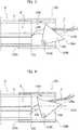
Figures 3 and 4 show possible subsequent usage steps of one or more embodiments, -
Figures 5 to 8 show possible features of one or more embodiments, -
Figure 9 exemplifies possible installation steps of one or more embodiments, and -
Figure 10 , substantially corresponding to a section along line X-X ofFigure 8 , shown in a magnified scale, exemplifies possible features of embodiments. - It will be appreciated that, for simplicity and clarity of illustration, the various Figures may not be drawn to the same scale.
- In the following description, various specific details are given to provide a thorough understanding of various exemplary embodiments of the present specification. One or more embodiments may be practiced without one or several specific details, or with other methods, components, materials, etc. In other instances, well-known structures, materials, or operations are not shown or described in detail in order to avoid obscuring various aspects of the embodiments. Reference throughout this specification to "one embodiment" or "an embodiment" means that a particular feature, structure, or characteristic described in connection with the embodiment is included in at least one embodiment. Thus, the possible appearances of the phrases "in one embodiment" or "in an embodiment" in various places throughout this specification are not necessarily all referring to the same embodiment. Furthermore, particular features, structures, or characteristics may be combined in any suitable manner in one or more embodiments.
- The headings provided herein are for convenience only, and therefore do not interpret the extent of protection or scope of the embodiments.
- In the Figures, reference M denotes a lighting device (module) having an elongate (optionally ribbon-like and/or flexible) shape, adapted to employ electrically-powered light radiation sources, e.g. solid-state light radiation sources (SSL) such as LED sources.
- Such modules M may include (see e.g.
Figure 10 ) a channel-shaped casing M12, hosting a support M14 substantially similar to a Printed Circuit Board (PCB) carrying electrically-powered light radiation sources M16, e.g. LED sources. - A sealing mass M18 including e.g. a diffusive light-permeable material is adapted to be inserted inside casing M12, thus providing a module M as considered herein with protection features against the penetration of foreign agents (e.g. having an IP protection degree). An optical element M180, e.g. having the properties of a lens, may be placed facing sources M14.
- The power supply (and optionally the control) of sources M16 may be implemented via electrical lines, exemplified herein as two lines M20 extending on support M12 lengthwise of module M.
- A module as module M (adapted to have any shape and size, e.g. having a cross section which may be rectangular - as in the presently illustrated non-limiting examples, - or square, polygonal, circular, etc.) may have a surface S, e.g. a front surface, wherefrom the light radiation is emitted.
- Lighting devices (modules) of the previously described exemplary type are known in the art, which makes it unnecessary to provide a more detailed description herein.
- Moreover, a module M as illustrated herein may be considered in itself as a module of indefinite length, adapted to be cut to length according to the application and usage needs.
- The cutting operation may originate end surfaces (which usually extend in a transversal plane with respect to the lengthwise extension of the module) which may be left uncovered, since the protection against the penetration of foreign agents may be jeopardized by the cutting operation.
- One or more embodiments may therefore provide a
connector 100 which, in addition to facilitating the mechanical and electrical connection (power supply and optionally control) of the light radiation sources, e.g. the sources denoted as M16 inFigure 10 , with one or more electric cables C, may favour achieving and/or maintaining protection features of the assembly of module M andconnector 100 against the penetration of foreign agents, e.g. with an IP protection degree. - In one or more embodiments,
connector 100 may include acasing 102 adapted to have a general tubular (closed or open) shape, with a section profile enabling the fitting thereof onto an end portion E of module M. - In one or more embodiments as exemplified in the Figures, module M may have a rectangular cross-section profile, and also casing 102 of
connector 100 may have a rectangular cross-section profile. In one or more embodiments, if module M has a different cross-section profile,connectors 100 may be used which have acasing 102 with a correspondingly different cross-section profile, so as to enableconnector 100 to be fitted onto an end portion E of module M, optionally in tight-fitting conditions. - It will be appreciated that the end portion E of module M onto which
connector 100 is adapted to be fitted may derive from cutting to length a module M initially having indefinite length. In one or more embodiments, reference E denotes any one of the mutually facing ends deriving from cutting to length a moduleM. A connector 100 according to one or more embodiments is thus adapted to be fitted also on fragments, i.e. scraps, deriving from cutting to length a module M. - In one or more embodiments,
casing 102 may be considered as having a "distal"end 102a, destined to be fitted onto module M and, on the opposite side, a "proximal"end 102b which is adapted, in one or more embodiments, e.g. exemplified inFigures 1 and8 , to be closed by anend cap 104, acting so to say as a closing plug ofcasing 102 ofconnector 100. - In one or more embodiments, said
cap 104 may be traversed (optionally sealingly closing and therefore safeguarding the protection degree) by one or more cables C, adapted to establish an electrical contact e.g. with lines M20 (Figure 10 ), so as to act as power supply and optionally control cables for the light radiation sources (e.g. M16) of module M. - In one or more embodiments,
connector 100 may include (mounted e.g. by means of pins or pivots on casing 102) atilting member 106, adapted to tilt back and forth about an axis X106 extending transversely of the longitudinal extension direction of casing 102 (and therefore of module M), denoted e.g. as X102 inFigures 3 to 7 . - For example, in one or more embodiments as exemplified herein, wherein module M of
connector 100 has a rectangular cross-section profile, axis X106 may extend in the direction of one of the pairs of sides (e.g. of the longer sides) of said section profile. - As schematically exemplified in
Figures 3 and 4 , in one ormore embodiments member 106 may be adapted to perform - with respect to axis X106 - a tilting (or swivelling) movement between: - a "proximal" return position, i.e. a position retracted away from
end 102a, which is to be fitted onto module M (seeFigure 3 ), and - a "distal" position, i.e. an advanced position, protruding towards
end 102a, which is to be fitted onto module M (seeFigure 4 ). - In one or more embodiments,
connector 100 may also be provided (e.g. at casing 102) with a stoppingformation 102c adapted to include e.g. a tooth or similar latch mechanism adapted to retain, e.g. by snap-fitting, the tiltingmember 106 in the advanced/distal position thereof (see e.g.Figures 4 to 7 ) . - In one or more embodiments casing 102,
cap 104 and tiltingmember 106 ofconnector 100 may comprise a moulded plastic material. - In one or more embodiments,
member 106 may be implemented as a prism-shaped body, e.g. with triangular cross-section, coupled by means of a pivot to the body ofconnector 100 in such a way as to locate axis X106 approximately at one of the edges ofprism 102. Of course, one or more embodiments may envisage amember 106 having a different shape. - In one or
more embodiments member 106 may carry, in a generally distal position, i.e. in aposition facing end 102a which is to be fitted on a module M, one or moreelectrical contacts 108 adapted to be connected to cable(s) C converging intoconnector 100. - For example, in the presently exemplified embodiments, wherein reference is made to the possible presence of two cables C adapted to establish an electrical contact with two lines M20 in module M, there may be provided two
contacts 108, e.g. positioned side by side. - The number of contacts 108 (optionally three or more) may be any number, selected as a function of the application and usage conditions.
- In one or more embodiments, the contact(s) 108 may have a tooth-like shape, e.g. a puncturing profile (having e.g. a sharp end).
- In one or more embodiments, contact (s) 108 may have a generally arch-shaped curved (e.g. at least approximately circular) profile, with the concavity facing axis X106.
- As a consequence (as it may be appreciated e.g. in the sequence of
Figures 3 and 4 ), the tilting movement ofmember 106 from the retracted or proximal position (Figure 3 ) to the advanced or distal position (Figure 4 ), thereby approachingend 102a fitted onto module M, may lead contact(s) 108 to penetrate into the end portion E of module M by puncturing it (e.g. at the location of the sealing mass M18). - In this way, contact(s) 108 may establish an electrical contact (optionally also with a certain puncturing effect) with electrically conductive lines M20 (
Figure 10 ) connected to the light radiation sources M16, supporting therefore the implementation of an electrical contact between the sources and cable(s) C. - Said penetrating movement, which is adapted to take place along a curved path (the centre whereof approximately corresponds to axis X106) originates moreover a sufficiently firm mechanical contact between
connector 100 and module M, since contact(s) 108 act as teeth which "bite" module M, so thatconnector 100 is anchored on module M. - In one or more embodiments, said puncturing movement may be supported by employing - for the portion of module M which is "bitten" by contact(s) 108 - a material such as silicone, into which contact (s) 108 may penetrate without requiring the exertion of a significant force in order to produce the corresponding tilting movement of
member 106a. - In one or more embodiments, member 106 (which may be e.g. prism-shaped) may have an
end 106a (e.g. an edge) adapted 106a to optionally protrude outsidecasing 102, and to perform the function of an actuating portion of the member, i.e. a portion which may be acted upon (e.g. by means of a finger) to tilt member 16 from the retracted position ofFigure 3 to the advanced position ofFigure 4 . - In one or more embodiments, the distance between contact (s) 108 and tilting axis X106 may be shorter than the distance between tilting axis X106 and
actuating portion 106a, which may be acted upon to tilt member 16. In this way a favourable lever effect is obtained, adapted to reduce the force which must be exerted to achieve the penetration of contact (s) 108 into module M. - In one or more embodiments, the presence of the stopping
element 102c may moreover helpmember 106 to remain in the distal position, where contact(s) 108 penetrate into module M. - In one or more embodiments (see e.g.
Figure 5 ),member 106 may be associated with a bias member 110 (e.g. a helical spring torsionally acting at the tilting axis X106), whichbiases member 106 towards the distal position, thus cooperating both with the penetration movement of contact(s) 108 into module M and with the action of retainingmember 106 in the distal position. - In one or more embodiments, the retention of contact(s) 108 in engagement with module M may be made firmer by locally applying adhesive matter.
- In one or more embodiments, the retention of
connector 100 fitted onto end E of module M may be supported by various means, e.g. by means of a double-sided adhesive tape 112 (visible inFigure 10 ) between casing M12 of module M and a wall facing the same of casing 102 ofconnector 100. - In one or more embodiments, a glue (e.g. a silicone adhesive) may be applied on the whole or on part of the surface of
connector 100 which is fitted onto end E of module M. - In one or more embodiments, one or more solutions for consolidating the connection described in the foregoing may help achieving a protection degree against the penetration of foreign agents, e.g. with an IP protection degree.
- In one or more embodiments, the sealing action of
connector 100 on end E of module M may optionally be strengthened by fitting and shrinking, around the portion ofconnector 100 which is coupled to module M, a cable tie 114 (see e.g.Figure 6 ) substantially similar to a hose clamp, e.g. as commonly used to ensure the tightness of hydraulic pipes. - In one or more embodiments, the body of
connector 100 may include, at least in thedistal portion 102a which is to be fitted onto module M, a deformable material (e.g. a plastic material, a silicone material, etc.) adapted to shrink around module M, with a clamping action which may be increased by applying a cable tie, such asband 114 exemplified inFigure 6 . - In one or more embodiments, the inner surface of
distal portion 102a ofconnector 100, which is to be fitted onto end E of module M, may be provided with tiny ribs (or generally speaking of sculptured formations) 116, having a height, e.g., of about 0.3-0.4 mm, adapted to perform a sealing function at least approximately similar to an O-ring. - The coupling of end cap or plug 104 with casing 102 (see the partially exploded perspective view of
Figure 8 ) may entail, in one or more embodiments, a coupling (by form fitting, e.g. a dovetail coupling, a male-female joint, etc. and/or by means of an adhesive) that is adapted to favour the achievement of an IP protection degree, which may also be quite high. This also applies to the passage of cable(s) C throughopenings 104a incap 104, which are adapted to be implemented (as commonly known) in such a way as to ensure a desired protection degree. -
Figure 9 exemplifies the possibility, offered by one or more embodiments, of mounting a lighting device including a module M having, associated thereto, aconnector 100 as exemplified herein, in installation conditions which are not easily achievable in traditional solutions. - For example,
Figure 9 exemplifies the possibility of realizing, into a mounting surface (e.g. wall W), a groove G wherein the assembly including module M andconnector 100 may be placed, as schematically illustrated in a dashed line inFigure 9 , i.e. with a minimum outward protrusion (practically flush with surface W). - For this purpose it is possible to take advantage of the fact that, as exemplified in
Figure 10 , connector 100 (the casing 12 whereof is shown inFigure 10 ) has cross-section dimensions which are slightly larger than module M. - In one or more embodiments, a mounting condition as exemplified in
Figure 9 may be easily achieved e.g. by applying, on the bottom of groove G, a double-sided adhesive tape T. - Finally, it will be appreciated that features or details exemplified with reference to one of the previously described Figures are adapted to be transposed (individually or in mutual combination) also to embodiments exemplified in different Figures.
- One or more embodiments may therefore concern an electrical connector (e.g. 100), including:
- a tubular casing (e.g. 102) having a longitudinal axis (e.g. X102) and a distal end (e.g. 102a) coupleable to an end portion (E) of an elongate lighting module (M),
- a tilting member (e.g. 106) adapted to tilt between a position retracted away from said distal end (see e.g.
Figure 3 ) and a position advanced towards said distal end (see e.g.Figure 4 ) about a tilting axis (e.g. X106) extending transversely of said longitudinal axis, and - at least one tooth-like electrical contact (see e.g. the two contacts 108) carried by said tilting member facing towards said distal end of the connector casing, the at least one electrical contact being adapted to penetrate into said end portion of the lighting module as a result of the tilting member tilting from said retracted position to said advanced position.
- In one or more embodiments, said at least one tooth-like contact may include a tapered puncturing shape.
- In one or more embodiments, said at least one tooth-like electrical contact may include an arched shape, with concavity towards said tilting axis.
- In one or more embodiments, said casing may include a proximal end (e.g. 102b) opposite said distal end, with said tilting member having an actuating portion adapted to protrude from said proximal end of the connector casing (at least when said tilting member is in said retracted position), wherein said tilting member is tiltable from said retracted position to said advanced position by force exerted on said actuating portion.
- In one or more embodiments, said casing may include a latch member (e.g. 102c) for latching, preferably by snap-fit action, the tilting member in said advanced position.
- One or more embodiments may include an elastic bias member, preferably a helical spring (e.g. 110) acting around said tilting axis, adapted to bias said tilting member towards said advanced position.
- One or more embodiments may include (in order to facilitate the sealing coupling of said distal end of the connector around said end portion of the lighting module) at least one feature out of:
- a band-like member (e.g. 114) arranged and shrinkable around said distal end of the connector casing, and/or
- surface sculpturing (e.g. 116) at the inner surface of the distal end of the connector casing, and/or
- adhesive matter (e.g. 112) at the inner surface of the distal end of the connector casing.
- In one or more embodiments, said casing may include a proximal end opposite said distal end with an end cap (e.g. 104) for sealingly closing said proximal end, said end cap optionally including a sealed passageway (e.g. 104a) for at least one electrical cable (e.g. C).
- One or more embodiments may concern a lighting device (M, 100), including:
- an elongate lighting module having an end portion, and
- an electrical connector according to one or more embodiments, arranged with said distal end coupled with said end portion of the lighting module, with said tilting member in said advanced position and said at least one tooth-like electrical contact penetrated into said end portion of the lighting module.
- A method according to one or more embodiments may include:
- providing an elongate lighting module having an end portion,
- providing an electrical connector according to one or more embodiments,
- coupling said electrical connector with said lighting module by coupling the distal end of the casing of the electrical connector with said end portion of the lighting module, with said tilting member in said proximal position, and
- tilting said tilting member to said distal position, wherein said at least one electrical contact penetrates said end portion of the lighting module.
- Without prejudice to the basic principles, the implementation details and the embodiments may vary, even appreciably, with respect to what has been described herein by way of non-limiting example only, without departing from the extent of protection.
- The extent of protection is defined by the annexed claims.
Claims (10)
- An electrical connector (100), including:- a tubular casing (102) having a longitudinal axis (X102) with a distal end (102a) coupleable to an end portion (E) of an elongate lighting module (M),- a tilting member (106) tiltable between a position retracted away from said distal end (102a) and a position advanced towards said distal end (102a) about a tilting axis (X106) extending transversely of said longitudinal axis (X102),- at least one tooth-like electrical contact (108) carried by said tilting member (106) facing towards said distal end (102a) of the connector casing (102), the at least one electrical contact (108) adapted to penetrate into said end portion (E) of the lighting module (M) as a result of the tilting member (106) tilting from said retracted position to said advanced position.
- The electrical connector (100) of claim 1, wherein said at least one tooth-like electrical contact (108) includes a tapered puncturing shape.
- The electrical connector (100) of claim 1 or claim 2, wherein said at least one tooth-like electrical contact (108) includes an arched shape, with concavity towards said tilting axis (X106).
- The electrical connector (100) of any of the previous claims, wherein said casing (102) includes a proximal end (102b) opposite said distal end (102a), with said tilting member (106) having an actuating portion (106a) adapted to protrude from said proximal end (102a) of the casing (102), wherein said tilting member (106) is tiltable from said retracted position to said advanced position by force exerted on said actuating portion (106a).
- The electrical connector (100) of any of the previous claims, wherein said casing (102) includes a latch member (102c) for latching, preferably by snap-fit action, the tilting member (106) in said advanced position.
- The electrical connector (100) of any of the previous claims, including a bias member, preferably a helical spring (110) acting around said tilting axis (106), biasing said tilting member (106) towards said advanced position.
- The electrical connector (100) of any of the previous claims, including at least one feature out of:- a band-like member (114) arranged and shrinkable around said distal end (102a) of the connector casing (102), and/or- surface sculpturing (116) at the inner surface of the distal end (102a) of the connector casing (102), and/or- adhesive matter (112) at the inner surface of the distal end (102a) of the connector casing (102).
- The electrical connector (100) of any of the previous claims, wherein said casing (102) includes a proximal end (102b) opposite said distal end (102a) with an end cap (104) for sealingly closing said proximal end (102b), said end cap (104) preferably including a sealed passageway (104a) for at least one electrical cable (C).
- A lighting device (M, 100) including:- an elongate lighting module (M) having an end portion (E), and- an electrical connector (100) according to any of claims 1 to 8 having said distal end (102a) coupled with said end portion (E) of said lighting module (M), with said tilting member (106) in said advanced position and said at least one tooth-like electrical contact (108) penetrated into said end portion (E) of the lighting module (M).
- A method including:- providing an elongate lighting module (M) having an end portion (E),- providing an electrical connector (100) according to any of claims 1 to 8,- coupling said electrical connector (100) with said lighting module (M) by coupling the distal end (102a) of the casing (102) of the electrical connector (100) with said end portion (E) of the lighting module (M) with said tilting member (106) in said retracted position, and- tilting said tilting member (106) to said advanced position, wherein said at least one tooth-like contact (108) penetrates said end portion (E) of the lighting module (M).
Applications Claiming Priority (1)
| Application Number | Priority Date | Filing Date | Title |
|---|---|---|---|
| IT201600111010 | 2016-11-04 |
Publications (2)
| Publication Number | Publication Date |
|---|---|
| EP3318799A1 true EP3318799A1 (en) | 2018-05-09 |
| EP3318799B1 EP3318799B1 (en) | 2019-06-19 |
Family
ID=58163073
Family Applications (1)
| Application Number | Title | Priority Date | Filing Date |
|---|---|---|---|
| EP17197271.4A Not-in-force EP3318799B1 (en) | 2016-11-04 | 2017-10-19 | A connector for lighting devices, corresponding lighting device and method |
Country Status (1)
| Country | Link |
|---|---|
| EP (1) | EP3318799B1 (en) |
Citations (5)
| Publication number | Priority date | Publication date | Assignee | Title |
|---|---|---|---|---|
| US5104331A (en) * | 1991-08-12 | 1992-04-14 | Goble Robert H | Damage resistant latching electrical connector |
| US6070996A (en) * | 1998-08-21 | 2000-06-06 | Mccollum; Robert W. | Pivotable stanchion assembly |
| US6299469B1 (en) * | 1999-04-22 | 2001-10-09 | Visteon Global Technologies, Inc. | Flexible circuit board splice clamp |
| EP2466701A1 (en) * | 2010-12-17 | 2012-06-20 | Alps Electric Co., Ltd. | Straight-tube LED lamp switch device and straight-tube LED lamp using the same |
| WO2013115722A1 (en) * | 2012-02-01 | 2013-08-08 | Strihl Scandinavia Ab | Easily mountable lighting luminaire and fitting arrangement |
-
2017
- 2017-10-19 EP EP17197271.4A patent/EP3318799B1/en not_active Not-in-force
Patent Citations (5)
| Publication number | Priority date | Publication date | Assignee | Title |
|---|---|---|---|---|
| US5104331A (en) * | 1991-08-12 | 1992-04-14 | Goble Robert H | Damage resistant latching electrical connector |
| US6070996A (en) * | 1998-08-21 | 2000-06-06 | Mccollum; Robert W. | Pivotable stanchion assembly |
| US6299469B1 (en) * | 1999-04-22 | 2001-10-09 | Visteon Global Technologies, Inc. | Flexible circuit board splice clamp |
| EP2466701A1 (en) * | 2010-12-17 | 2012-06-20 | Alps Electric Co., Ltd. | Straight-tube LED lamp switch device and straight-tube LED lamp using the same |
| WO2013115722A1 (en) * | 2012-02-01 | 2013-08-08 | Strihl Scandinavia Ab | Easily mountable lighting luminaire and fitting arrangement |
Also Published As
| Publication number | Publication date |
|---|---|
| EP3318799B1 (en) | 2019-06-19 |
Similar Documents
| Publication | Publication Date | Title |
|---|---|---|
| US5662408A (en) | Simple plug in night light having a low profile | |
| US9812831B2 (en) | Connector for lighting devices and corresponding method | |
| ATE365384T1 (en) | ELECTRICAL CONTACT ELEMENT | |
| US20160365656A1 (en) | Connector for lighting devices, corresponding accessory and method | |
| ATE282900T1 (en) | FLEXIBLE ELONGATED CONNECTOR | |
| RU2001101877A (en) | SEALING ELEMENT FOR CABLE HEADSET | |
| EP3318799B1 (en) | A connector for lighting devices, corresponding lighting device and method | |
| WO2004004074A1 (en) | Instant cable connector for electrical components or devices | |
| ES2300037T3 (en) | DEVICE FOR ELECTRICAL CONNECTION OF DISCONTINUOUS DRIVERS. | |
| US7285014B2 (en) | Cord connector having a water-resistant seal | |
| ES2411699T5 (en) | Cable support device | |
| JP2002075483A (en) | Connector for electric wire connection | |
| CN107293865B (en) | Connector assembly with bidirectional clamping structure | |
| KR200479319Y1 (en) | Water preventing connector cover | |
| PT74698B (en) | ELECTRIC CABLE WITH ANGLE PROTECTION | |
| ES2383171T3 (en) | Electrical connector with isolation displacement contacts | |
| BRPI0514414A (en) | angled connector with a bracket that secures the use position of the two angled tabs | |
| CN113964555A (en) | Cable crimping device for electric power engineering | |
| DE59914108D1 (en) | Cable gland | |
| ITMI980887A1 (en) | TERMINAL FOR CONNECTION TO A POWER CABLE WITH TWO INSULATING ELEMENTS | |
| KR200161440Y1 (en) | Waterproof plug/connector | |
| CN220439985U (en) | Waterproof wire connector | |
| ATE235748T1 (en) | CONNECTOR FOR COAXIAL CABLES WITH AN INTEGRATED CABLE-GRIPPING EXTERNAL SOCKET | |
| ES1044530U (en) | LOCKING ELEMENT FOR ELECTRICAL CONNECTOR ASSEMBLY. | |
| GB2405267A (en) | Sealing covers for electrical connector block |
Legal Events
| Date | Code | Title | Description |
|---|---|---|---|
| PUAI | Public reference made under article 153(3) epc to a published international application that has entered the european phase |
Free format text: ORIGINAL CODE: 0009012 |
|
| STAA | Information on the status of an ep patent application or granted ep patent |
Free format text: STATUS: THE APPLICATION HAS BEEN PUBLISHED |
|
| AK | Designated contracting states |
Kind code of ref document: A1 Designated state(s): AL AT BE BG CH CY CZ DE DK EE ES FI FR GB GR HR HU IE IS IT LI LT LU LV MC MK MT NL NO PL PT RO RS SE SI SK SM TR |
|
| AX | Request for extension of the european patent |
Extension state: BA ME |
|
| RAP1 | Party data changed (applicant data changed or rights of an application transferred) |
Owner name: OSRAM GMBH Owner name: OSRAM S.P.A. - SOCIETA' RIUNITE OSRAM EDISON CLERI |
|
| STAA | Information on the status of an ep patent application or granted ep patent |
Free format text: STATUS: REQUEST FOR EXAMINATION WAS MADE |
|
| 17P | Request for examination filed |
Effective date: 20181017 |
|
| RBV | Designated contracting states (corrected) |
Designated state(s): AL AT BE BG CH CY CZ DE DK EE ES FI FR GB GR HR HU IE IS IT LI LT LU LV MC MK MT NL NO PL PT RO RS SE SI SK SM TR |
|
| GRAP | Despatch of communication of intention to grant a patent |
Free format text: ORIGINAL CODE: EPIDOSNIGR1 |
|
| STAA | Information on the status of an ep patent application or granted ep patent |
Free format text: STATUS: GRANT OF PATENT IS INTENDED |
|
| INTG | Intention to grant announced |
Effective date: 20190123 |
|
| RIN1 | Information on inventor provided before grant (corrected) |
Inventor name: BOBBO, SIMON Inventor name: ZANOTTO, ALBERTO Inventor name: DIDONE', ROBERTO |
|
| GRAS | Grant fee paid |
Free format text: ORIGINAL CODE: EPIDOSNIGR3 |
|
| GRAA | (expected) grant |
Free format text: ORIGINAL CODE: 0009210 |
|
| STAA | Information on the status of an ep patent application or granted ep patent |
Free format text: STATUS: THE PATENT HAS BEEN GRANTED |
|
| AK | Designated contracting states |
Kind code of ref document: B1 Designated state(s): AL AT BE BG CH CY CZ DE DK EE ES FI FR GB GR HR HU IE IS IT LI LT LU LV MC MK MT NL NO PL PT RO RS SE SI SK SM TR |
|
| REG | Reference to a national code |
Ref country code: GB Ref legal event code: FG4D |
|
| REG | Reference to a national code |
Ref country code: CH Ref legal event code: EP |
|
| REG | Reference to a national code |
Ref country code: IE Ref legal event code: FG4D |
|
| REG | Reference to a national code |
Ref country code: AT Ref legal event code: REF Ref document number: 1146003 Country of ref document: AT Kind code of ref document: T Effective date: 20190715 |
|
| REG | Reference to a national code |
Ref country code: DE Ref legal event code: R096 Ref document number: 602017004653 Country of ref document: DE |
|
| REG | Reference to a national code |
Ref country code: NL Ref legal event code: MP Effective date: 20190619 |
|
| PG25 | Lapsed in a contracting state [announced via postgrant information from national office to epo] |
Ref country code: AL Free format text: LAPSE BECAUSE OF FAILURE TO SUBMIT A TRANSLATION OF THE DESCRIPTION OR TO PAY THE FEE WITHIN THE PRESCRIBED TIME-LIMIT Effective date: 20190619 Ref country code: FI Free format text: LAPSE BECAUSE OF FAILURE TO SUBMIT A TRANSLATION OF THE DESCRIPTION OR TO PAY THE FEE WITHIN THE PRESCRIBED TIME-LIMIT Effective date: 20190619 Ref country code: LT Free format text: LAPSE BECAUSE OF FAILURE TO SUBMIT A TRANSLATION OF THE DESCRIPTION OR TO PAY THE FEE WITHIN THE PRESCRIBED TIME-LIMIT Effective date: 20190619 Ref country code: HR Free format text: LAPSE BECAUSE OF FAILURE TO SUBMIT A TRANSLATION OF THE DESCRIPTION OR TO PAY THE FEE WITHIN THE PRESCRIBED TIME-LIMIT Effective date: 20190619 Ref country code: SE Free format text: LAPSE BECAUSE OF FAILURE TO SUBMIT A TRANSLATION OF THE DESCRIPTION OR TO PAY THE FEE WITHIN THE PRESCRIBED TIME-LIMIT Effective date: 20190619 Ref country code: NO Free format text: LAPSE BECAUSE OF FAILURE TO SUBMIT A TRANSLATION OF THE DESCRIPTION OR TO PAY THE FEE WITHIN THE PRESCRIBED TIME-LIMIT Effective date: 20190919 |
|
| REG | Reference to a national code |
Ref country code: LT Ref legal event code: MG4D |
|
| PG25 | Lapsed in a contracting state [announced via postgrant information from national office to epo] |
Ref country code: RS Free format text: LAPSE BECAUSE OF FAILURE TO SUBMIT A TRANSLATION OF THE DESCRIPTION OR TO PAY THE FEE WITHIN THE PRESCRIBED TIME-LIMIT Effective date: 20190619 Ref country code: GR Free format text: LAPSE BECAUSE OF FAILURE TO SUBMIT A TRANSLATION OF THE DESCRIPTION OR TO PAY THE FEE WITHIN THE PRESCRIBED TIME-LIMIT Effective date: 20190920 Ref country code: BG Free format text: LAPSE BECAUSE OF FAILURE TO SUBMIT A TRANSLATION OF THE DESCRIPTION OR TO PAY THE FEE WITHIN THE PRESCRIBED TIME-LIMIT Effective date: 20190919 Ref country code: LV Free format text: LAPSE BECAUSE OF FAILURE TO SUBMIT A TRANSLATION OF THE DESCRIPTION OR TO PAY THE FEE WITHIN THE PRESCRIBED TIME-LIMIT Effective date: 20190619 |
|
| REG | Reference to a national code |
Ref country code: AT Ref legal event code: MK05 Ref document number: 1146003 Country of ref document: AT Kind code of ref document: T Effective date: 20190619 |
|
| PG25 | Lapsed in a contracting state [announced via postgrant information from national office to epo] |
Ref country code: CZ Free format text: LAPSE BECAUSE OF FAILURE TO SUBMIT A TRANSLATION OF THE DESCRIPTION OR TO PAY THE FEE WITHIN THE PRESCRIBED TIME-LIMIT Effective date: 20190619 Ref country code: NL Free format text: LAPSE BECAUSE OF FAILURE TO SUBMIT A TRANSLATION OF THE DESCRIPTION OR TO PAY THE FEE WITHIN THE PRESCRIBED TIME-LIMIT Effective date: 20190619 Ref country code: RO Free format text: LAPSE BECAUSE OF FAILURE TO SUBMIT A TRANSLATION OF THE DESCRIPTION OR TO PAY THE FEE WITHIN THE PRESCRIBED TIME-LIMIT Effective date: 20190619 Ref country code: AT Free format text: LAPSE BECAUSE OF FAILURE TO SUBMIT A TRANSLATION OF THE DESCRIPTION OR TO PAY THE FEE WITHIN THE PRESCRIBED TIME-LIMIT Effective date: 20190619 Ref country code: PT Free format text: LAPSE BECAUSE OF FAILURE TO SUBMIT A TRANSLATION OF THE DESCRIPTION OR TO PAY THE FEE WITHIN THE PRESCRIBED TIME-LIMIT Effective date: 20191021 Ref country code: EE Free format text: LAPSE BECAUSE OF FAILURE TO SUBMIT A TRANSLATION OF THE DESCRIPTION OR TO PAY THE FEE WITHIN THE PRESCRIBED TIME-LIMIT Effective date: 20190619 Ref country code: SK Free format text: LAPSE BECAUSE OF FAILURE TO SUBMIT A TRANSLATION OF THE DESCRIPTION OR TO PAY THE FEE WITHIN THE PRESCRIBED TIME-LIMIT Effective date: 20190619 |
|
| PG25 | Lapsed in a contracting state [announced via postgrant information from national office to epo] |
Ref country code: IT Free format text: LAPSE BECAUSE OF FAILURE TO SUBMIT A TRANSLATION OF THE DESCRIPTION OR TO PAY THE FEE WITHIN THE PRESCRIBED TIME-LIMIT Effective date: 20190619 Ref country code: IS Free format text: LAPSE BECAUSE OF FAILURE TO SUBMIT A TRANSLATION OF THE DESCRIPTION OR TO PAY THE FEE WITHIN THE PRESCRIBED TIME-LIMIT Effective date: 20191019 Ref country code: SM Free format text: LAPSE BECAUSE OF FAILURE TO SUBMIT A TRANSLATION OF THE DESCRIPTION OR TO PAY THE FEE WITHIN THE PRESCRIBED TIME-LIMIT Effective date: 20190619 Ref country code: ES Free format text: LAPSE BECAUSE OF FAILURE TO SUBMIT A TRANSLATION OF THE DESCRIPTION OR TO PAY THE FEE WITHIN THE PRESCRIBED TIME-LIMIT Effective date: 20190619 |
|
| PG25 | Lapsed in a contracting state [announced via postgrant information from national office to epo] |
Ref country code: TR Free format text: LAPSE BECAUSE OF FAILURE TO SUBMIT A TRANSLATION OF THE DESCRIPTION OR TO PAY THE FEE WITHIN THE PRESCRIBED TIME-LIMIT Effective date: 20190619 |
|
| PG25 | Lapsed in a contracting state [announced via postgrant information from national office to epo] |
Ref country code: DK Free format text: LAPSE BECAUSE OF FAILURE TO SUBMIT A TRANSLATION OF THE DESCRIPTION OR TO PAY THE FEE WITHIN THE PRESCRIBED TIME-LIMIT Effective date: 20190619 Ref country code: PL Free format text: LAPSE BECAUSE OF FAILURE TO SUBMIT A TRANSLATION OF THE DESCRIPTION OR TO PAY THE FEE WITHIN THE PRESCRIBED TIME-LIMIT Effective date: 20190619 |
|
| PG25 | Lapsed in a contracting state [announced via postgrant information from national office to epo] |
Ref country code: MC Free format text: LAPSE BECAUSE OF FAILURE TO SUBMIT A TRANSLATION OF THE DESCRIPTION OR TO PAY THE FEE WITHIN THE PRESCRIBED TIME-LIMIT Effective date: 20190619 Ref country code: IS Free format text: LAPSE BECAUSE OF FAILURE TO SUBMIT A TRANSLATION OF THE DESCRIPTION OR TO PAY THE FEE WITHIN THE PRESCRIBED TIME-LIMIT Effective date: 20200224 |
|
| REG | Reference to a national code |
Ref country code: DE Ref legal event code: R097 Ref document number: 602017004653 Country of ref document: DE |
|
| PLBE | No opposition filed within time limit |
Free format text: ORIGINAL CODE: 0009261 |
|
| STAA | Information on the status of an ep patent application or granted ep patent |
Free format text: STATUS: NO OPPOSITION FILED WITHIN TIME LIMIT |
|
| PG2D | Information on lapse in contracting state deleted |
Ref country code: IS |
|
| PG25 | Lapsed in a contracting state [announced via postgrant information from national office to epo] |
Ref country code: LU Free format text: LAPSE BECAUSE OF NON-PAYMENT OF DUE FEES Effective date: 20191019 |
|
| 26N | No opposition filed |
Effective date: 20200603 |
|
| REG | Reference to a national code |
Ref country code: BE Ref legal event code: MM Effective date: 20191031 |
|
| PG25 | Lapsed in a contracting state [announced via postgrant information from national office to epo] |
Ref country code: BE Free format text: LAPSE BECAUSE OF NON-PAYMENT OF DUE FEES Effective date: 20191031 Ref country code: SI Free format text: LAPSE BECAUSE OF FAILURE TO SUBMIT A TRANSLATION OF THE DESCRIPTION OR TO PAY THE FEE WITHIN THE PRESCRIBED TIME-LIMIT Effective date: 20190619 |
|
| PG25 | Lapsed in a contracting state [announced via postgrant information from national office to epo] |
Ref country code: FR Free format text: LAPSE BECAUSE OF NON-PAYMENT OF DUE FEES Effective date: 20191031 Ref country code: IE Free format text: LAPSE BECAUSE OF NON-PAYMENT OF DUE FEES Effective date: 20191019 |
|
| PG25 | Lapsed in a contracting state [announced via postgrant information from national office to epo] |
Ref country code: CY Free format text: LAPSE BECAUSE OF FAILURE TO SUBMIT A TRANSLATION OF THE DESCRIPTION OR TO PAY THE FEE WITHIN THE PRESCRIBED TIME-LIMIT Effective date: 20190619 |
|
| REG | Reference to a national code |
Ref country code: CH Ref legal event code: PL |
|
| PG25 | Lapsed in a contracting state [announced via postgrant information from national office to epo] |
Ref country code: LI Free format text: LAPSE BECAUSE OF FAILURE TO SUBMIT A TRANSLATION OF THE DESCRIPTION OR TO PAY THE FEE WITHIN THE PRESCRIBED TIME-LIMIT Effective date: 20201031 Ref country code: CH Free format text: LAPSE BECAUSE OF FAILURE TO SUBMIT A TRANSLATION OF THE DESCRIPTION OR TO PAY THE FEE WITHIN THE PRESCRIBED TIME-LIMIT Effective date: 20201031 |
|
| PG25 | Lapsed in a contracting state [announced via postgrant information from national office to epo] |
Ref country code: MT Free format text: LAPSE BECAUSE OF FAILURE TO SUBMIT A TRANSLATION OF THE DESCRIPTION OR TO PAY THE FEE WITHIN THE PRESCRIBED TIME-LIMIT Effective date: 20190619 Ref country code: HU Free format text: LAPSE BECAUSE OF FAILURE TO SUBMIT A TRANSLATION OF THE DESCRIPTION OR TO PAY THE FEE WITHIN THE PRESCRIBED TIME-LIMIT; INVALID AB INITIO Effective date: 20171019 |
|
| GBPC | Gb: european patent ceased through non-payment of renewal fee |
Effective date: 20211019 |
|
| PG25 | Lapsed in a contracting state [announced via postgrant information from national office to epo] |
Ref country code: MK Free format text: LAPSE BECAUSE OF FAILURE TO SUBMIT A TRANSLATION OF THE DESCRIPTION OR TO PAY THE FEE WITHIN THE PRESCRIBED TIME-LIMIT Effective date: 20190619 |
|
| PG25 | Lapsed in a contracting state [announced via postgrant information from national office to epo] |
Ref country code: GB Free format text: LAPSE BECAUSE OF NON-PAYMENT OF DUE FEES Effective date: 20211019 |
|
| REG | Reference to a national code |
Ref country code: DE Ref legal event code: R081 Ref document number: 602017004653 Country of ref document: DE Owner name: OPTOTRONIC GMBH, DE Free format text: FORMER OWNER: OSRAM GMBH, 80807 MUENCHEN, DE Ref country code: DE Ref legal event code: R081 Ref document number: 602017004653 Country of ref document: DE Owner name: INVENTRONICS GMBH, DE Free format text: FORMER OWNER: OSRAM GMBH, 80807 MUENCHEN, DE |
|
| PGFP | Annual fee paid to national office [announced via postgrant information from national office to epo] |
Ref country code: DE Payment date: 20231018 Year of fee payment: 7 |
|
| REG | Reference to a national code |
Ref country code: DE Ref legal event code: R081 Ref document number: 602017004653 Country of ref document: DE Owner name: INVENTRONICS GMBH, DE Free format text: FORMER OWNER: OPTOTRONIC GMBH, 85748 GARCHING, DE |
|
| REG | Reference to a national code |
Ref country code: DE Ref legal event code: R119 Ref document number: 602017004653 Country of ref document: DE |
|
| PG25 | Lapsed in a contracting state [announced via postgrant information from national office to epo] |
Ref country code: DE Free format text: LAPSE BECAUSE OF NON-PAYMENT OF DUE FEES Effective date: 20250501 |