EP3318728A1 - Variable volume bearing compartment - Google Patents
Variable volume bearing compartment Download PDFInfo
- Publication number
- EP3318728A1 EP3318728A1 EP17189123.7A EP17189123A EP3318728A1 EP 3318728 A1 EP3318728 A1 EP 3318728A1 EP 17189123 A EP17189123 A EP 17189123A EP 3318728 A1 EP3318728 A1 EP 3318728A1
- Authority
- EP
- European Patent Office
- Prior art keywords
- bearing compartment
- plenum
- pressure
- volume
- value
- Prior art date
- Legal status (The legal status is an assumption and is not a legal conclusion. Google has not performed a legal analysis and makes no representation as to the accuracy of the status listed.)
- Granted
Links
Images



Classifications
-
- F—MECHANICAL ENGINEERING; LIGHTING; HEATING; WEAPONS; BLASTING
- F01—MACHINES OR ENGINES IN GENERAL; ENGINE PLANTS IN GENERAL; STEAM ENGINES
- F01D—NON-POSITIVE DISPLACEMENT MACHINES OR ENGINES, e.g. STEAM TURBINES
- F01D25/00—Component parts, details, or accessories, not provided for in, or of interest apart from, other groups
- F01D25/16—Arrangement of bearings; Supporting or mounting bearings in casings
-
- F—MECHANICAL ENGINEERING; LIGHTING; HEATING; WEAPONS; BLASTING
- F16—ENGINEERING ELEMENTS AND UNITS; GENERAL MEASURES FOR PRODUCING AND MAINTAINING EFFECTIVE FUNCTIONING OF MACHINES OR INSTALLATIONS; THERMAL INSULATION IN GENERAL
- F16C—SHAFTS; FLEXIBLE SHAFTS; ELEMENTS OR CRANKSHAFT MECHANISMS; ROTARY BODIES OTHER THAN GEARING ELEMENTS; BEARINGS
- F16C33/00—Parts of bearings; Special methods for making bearings or parts thereof
- F16C33/72—Sealings
- F16C33/76—Sealings of ball or roller bearings
- F16C33/762—Sealings of ball or roller bearings by means of a fluid
- F16C33/763—Sealings of ball or roller bearings by means of a fluid retained in the sealing gap
- F16C33/766—Sealings of ball or roller bearings by means of a fluid retained in the sealing gap by pumping action
-
- F—MECHANICAL ENGINEERING; LIGHTING; HEATING; WEAPONS; BLASTING
- F01—MACHINES OR ENGINES IN GENERAL; ENGINE PLANTS IN GENERAL; STEAM ENGINES
- F01D—NON-POSITIVE DISPLACEMENT MACHINES OR ENGINES, e.g. STEAM TURBINES
- F01D25/00—Component parts, details, or accessories, not provided for in, or of interest apart from, other groups
- F01D25/16—Arrangement of bearings; Supporting or mounting bearings in casings
- F01D25/162—Bearing supports
-
- F—MECHANICAL ENGINEERING; LIGHTING; HEATING; WEAPONS; BLASTING
- F02—COMBUSTION ENGINES; HOT-GAS OR COMBUSTION-PRODUCT ENGINE PLANTS
- F02C—GAS-TURBINE PLANTS; AIR INTAKES FOR JET-PROPULSION PLANTS; CONTROLLING FUEL SUPPLY IN AIR-BREATHING JET-PROPULSION PLANTS
- F02C7/00—Features, components parts, details or accessories, not provided for in, or of interest apart form groups F02C1/00 - F02C6/00; Air intakes for jet-propulsion plants
- F02C7/06—Arrangements of bearings; Lubricating
-
- F—MECHANICAL ENGINEERING; LIGHTING; HEATING; WEAPONS; BLASTING
- F16—ENGINEERING ELEMENTS AND UNITS; GENERAL MEASURES FOR PRODUCING AND MAINTAINING EFFECTIVE FUNCTIONING OF MACHINES OR INSTALLATIONS; THERMAL INSULATION IN GENERAL
- F16C—SHAFTS; FLEXIBLE SHAFTS; ELEMENTS OR CRANKSHAFT MECHANISMS; ROTARY BODIES OTHER THAN GEARING ELEMENTS; BEARINGS
- F16C33/00—Parts of bearings; Special methods for making bearings or parts thereof
- F16C33/72—Sealings
- F16C33/726—Sealings with means to vent the interior of the bearing
-
- F—MECHANICAL ENGINEERING; LIGHTING; HEATING; WEAPONS; BLASTING
- F16—ENGINEERING ELEMENTS AND UNITS; GENERAL MEASURES FOR PRODUCING AND MAINTAINING EFFECTIVE FUNCTIONING OF MACHINES OR INSTALLATIONS; THERMAL INSULATION IN GENERAL
- F16C—SHAFTS; FLEXIBLE SHAFTS; ELEMENTS OR CRANKSHAFT MECHANISMS; ROTARY BODIES OTHER THAN GEARING ELEMENTS; BEARINGS
- F16C35/00—Rigid support of bearing units; Housings, e.g. caps, covers
- F16C35/04—Rigid support of bearing units; Housings, e.g. caps, covers in the case of ball or roller bearings
-
- F—MECHANICAL ENGINEERING; LIGHTING; HEATING; WEAPONS; BLASTING
- F05—INDEXING SCHEMES RELATING TO ENGINES OR PUMPS IN VARIOUS SUBCLASSES OF CLASSES F01-F04
- F05D—INDEXING SCHEME FOR ASPECTS RELATING TO NON-POSITIVE-DISPLACEMENT MACHINES OR ENGINES, GAS-TURBINES OR JET-PROPULSION PLANTS
- F05D2220/00—Application
- F05D2220/30—Application in turbines
- F05D2220/32—Application in turbines in gas turbines
-
- F—MECHANICAL ENGINEERING; LIGHTING; HEATING; WEAPONS; BLASTING
- F05—INDEXING SCHEMES RELATING TO ENGINES OR PUMPS IN VARIOUS SUBCLASSES OF CLASSES F01-F04
- F05D—INDEXING SCHEME FOR ASPECTS RELATING TO NON-POSITIVE-DISPLACEMENT MACHINES OR ENGINES, GAS-TURBINES OR JET-PROPULSION PLANTS
- F05D2260/00—Function
- F05D2260/60—Fluid transfer
- F05D2260/605—Venting into the ambient atmosphere or the like
-
- F—MECHANICAL ENGINEERING; LIGHTING; HEATING; WEAPONS; BLASTING
- F16—ENGINEERING ELEMENTS AND UNITS; GENERAL MEASURES FOR PRODUCING AND MAINTAINING EFFECTIVE FUNCTIONING OF MACHINES OR INSTALLATIONS; THERMAL INSULATION IN GENERAL
- F16C—SHAFTS; FLEXIBLE SHAFTS; ELEMENTS OR CRANKSHAFT MECHANISMS; ROTARY BODIES OTHER THAN GEARING ELEMENTS; BEARINGS
- F16C2360/00—Engines or pumps
- F16C2360/23—Gas turbine engines
Definitions
- FIG. 3C is a close-up schematic cross-sectional view indicated by circle 3 in FIG. 3A of the RVV 74 in another additional volume position.
- piston 76 is positioned between piston stops 86A and 86B.
- the force F B from the pressure of air buffer system 68 (shown in FIG. 2 ) is balanced with the force F C from the pressure of bearing compartment 54 plus the spring force F S from spring 90.
- RVV 74 provides additional volume to bearing compartment 54, but RVV 74 can provide more or less additional volume.
- FIG. 5 is a flow chart of a method of pressurizing bearing compartment assembly 58 of FIG. 2 . Please note that the components used in the flow chart are illustrated in FIGS. 1-4 .
- bearing compartment assembly can further comprise: an elastic member that biases the displaceable member toward the additional volume position.
- a gas turbine engine can comprise: the bearing compartment of claim 1; a stationary component; a rotating component; and wherein the bearing can be positioned between the stationary component and the rotating component; and wherein the reactive volume vessel can be positioned exterior to the bearing compartment in an upper half of the gas turbine engine.
- the reactive volume vessel of the preceding paragraph can optionally include, additionally and/or alternatively, any one or more of the following features, configurations and/or additional components:
Landscapes
- Engineering & Computer Science (AREA)
- General Engineering & Computer Science (AREA)
- Mechanical Engineering (AREA)
- Chemical & Material Sciences (AREA)
- Combustion & Propulsion (AREA)
- Support Of The Bearing (AREA)
Abstract
Description
- The present invention relates generally to fluid systems, and more particularly to a pressurization system for a gas turbine engine.
- There are a variety of known gas turbine engine configurations, including two-spool, high-bypass engines. Such an engine typically includes a high pressure spool, a combustion system and a low pressure spool disposed within an engine case to form a generally axial, serial flow path about the engine centerline. The high pressure spool includes a high pressure turbine, a high pressure shaft extending axially forward from the high pressure turbine, and a high pressure compressor connected to a forward end of the high pressure shaft. The low pressure spool includes a low pressure turbine, which is disposed downstream of the high pressure turbine, a low pressure shaft, which typically extends coaxially through the high pressure shaft, and a low pressure compressor connected to a forward end of the low pressure shaft, forward of the high pressure compressor. A fan is also connected to the low pressure spool, forward of the low pressure compressor. The combustion system is disposed between the high pressure compressor and the high pressure turbine and receives compressed air from the compressors and fuel provided by a fuel injection system. A combustion process is carried out within the combustion system to produce high energy exhaust gases to produce thrust and turn the high and low pressure turbines, which drive their respective compressors and the fan to sustain the combustion process.
- Because there are rotating components within the stationary components of a gas turbine engine, bearings are installed to promote smooth and efficient operation. Traditionally, the bearings are bathed in lubricating oil that is pumped into and scavenged out of the inside of the bearing compartment. The exterior of the bearing compartment is pressurized by an air buffer system to inhibit oil from inside of the compartment leaking outside of the compartment. There may be transient operational conditions where the air buffer system is not providing sufficient pressure to inhibit leakage from the bearing compartment.
- In one embodiment, a bearing compartment assembly includes a bearing compartment with a bearing and a plenum, a buffer system that supplies pressure to an exterior of the bearing compartment, and a reactive volume vessel connected to the bearing compartment. The reactive volume vessel has a displaceable member that is movable between two positions, and moving the displaceable member causes the total volume of the bearing compartment to change.
- In another embodiment, a method of operating a bearing compartment assembly includes pressurizing an exterior of the bearing compartment and pressurizing a plenum inside a bearing compartment. In addition, the exterior pressure and the plenum pressure are changed, and the volume of the plenum in increased to prevent the buffer pressure from decreasing below the plenum pressure.
- The present summary is provided only by way of example, and not limitation. Other aspects of the present disclosure will be appreciated in view of the entirety of the present disclosure, including the entire text, claims and accompanying figures.
-
-
FIG. 1 is a schematic cross-sectional view of a gas turbine engine. -
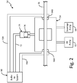
FIG. 2 is a schematic view of a bearing compartment assembly from the gas turbine engine ofFIG. 1 . -
FIG. 3A is a schematic cross-sectional view of the gas turbine engine ofFIG. 1 along line 3-3 including a reactive volume vessel in a standard volume position. -
FIG. 3B is a close-up schematic cross-sectional view indicated bycircle 3 inFIG. 3A of the reactive volume vessel in a maximum additional volume position. -
FIG. 3C is a close-up schematic cross-sectional view indicated bycircle 3 inFIG. 3A of the reactive volume vessel in another additional volume position. -
FIG. 4 is a graph of pressure versus time and position versus time for a bearing compartment and a reactive volume vessel of the bearing compartment assembly. -
FIG. 5 is a flow chart of a method of pressurizing the bearing compartment assembly ofFIG. 2 . -
FIG. 6 is a schematic view of an alternate embodiment bearing compartment assembly. - While the above-identified figures set forth embodiments of the present invention, other embodiments are also contemplated, as noted in the discussion. In all cases, this disclosure presents the invention by way of representation and not limitation. It should be understood that numerous other modifications and embodiments can be devised by those skilled in the art, which fall within the scope and spirit of the principles of the invention. The figures may not be drawn to scale, and applications and embodiments of the present invention may include features, steps and/or components not specifically shown in the drawings.
-
FIG. 1 is a schematic side cross-sectional view ofgas turbine engine 10 for an aircraft (not shown). Shown inFIG. 1 aregas turbine engine 10,fan 12, low pressure compressor (LPC) 14, high pressure compressor (HPC) 16,combustor section 18, high pressure turbine (HPT) 20, low pressure turbine (LPT) 22,fan case 24,LPC case 26, HPCcase 28,combustor case 29, HPTcase 30,LPT case 32,low pressure shaft 34,high pressure shaft 36, fanexit guide vanes 38,fuel injectors 40,HPT blades 42, LPT blades 44,support rotor 46,first bearing compartment 48,second bearing compartment 50, third bearingcompartment 52,fourth bearing compartment 54,fifth bearing compartment 56, inlet air A, exhaust air AE, primary air AP, secondary air As (also known as bypass air), and longitudinal engine centerline axis CL. - In the illustrated embodiment,
gas turbine engine 10 comprises a dual-spool turbofan engine, although other engine configurations are possible in alternative embodiments.Gas turbine engine 10, of which the operational principles are well known in the art, comprisesfan 12,LPC 14, HPC 16,combustor section 18, HPT 20, andLPT 22, which are each concentrically disposed around longitudinal engine centerline axis CL. Fan 12 is enclosed at its outer diameter withinfan case 24. Likewise, the other engine components are correspondingly enclosed at their outer diameters within various engine casings, includingLPC case 26, HPCcase 28,combustor case 29, HPTcase 30 andLPT case 32.Fan 12 andLPC 14 are connected toLPT 22 throughlow pressure shaft 34, and together withfan 12,LPC 14,LPT 22, andlow pressure shaft 34 comprise the low pressure spool. HPC 16 is connected to HPT 20 throughhigh pressure shaft 36, and together HPC 16, HPT 20, andhigh pressure shaft 36 comprise the high pressure spool. - During normal operation, inlet air A enters
engine 10 where it is divided into streams of primary air AP and secondary air As after passing throughfan 12.Fan 12 is rotated byLPT 22 through low pressure shaft 34 (either directly as shown or through a gearbox, not shown) to accelerate secondary air As (also known as bypass air) through fanexit guide vanes 38, thereby producing a major portion of the thrust output ofengine 10. Primary air AP (also known as gas path air) is directed first intoLPC 14 and then intoHPC 16.LPC 14 and HPC 16 work together to incrementally increase the pressure of primary air AP. HPC 16 is rotated by HPT 20 throughhigh pressure shaft 36 to provide primary air AP tocombustor section 18. The compressed air is delivered tocombustor section 18, along with fuel throughfuel injectors 40, such that this fuel-air mixture is ignited by ignitors (not shown) thus resulting in a combustion process which can be carried out to produce the high energy gases necessary to turnHPT 20 andLPT 22. These high energy gases continue throughgas turbine engine 10 whereby they are typically passed through an exhaust nozzle (not shown) to further produce thrust. - After being compressed in
LPC 14 andHPC 16 and participating in a combustion process incombustor section 18 to increase pressure and energy, primary air AP is mixed with fuel in thecombustor section 18. This fuel-air mixture is ignited by ignitors (not shown) and burned in thecombustor section 18 producing exhaust air AE. Exhaust air AE flows through HPT 20 andLPT 22 such thatHPT blades 42 and LPT blades 44 extract energy from the flow of exhaust air AE. Exhaust air AE impinges onHPT blades 42 to cause rotation ofhigh pressure shaft 36, which turnsHPC 16. Exhaust air AE also impinges on LPT blades 44 to cause rotation ofsupport rotor 46 andlow pressure shaft 34, which turnsfan 12 andLPC 14. - In order to provide stability for and reduce the friction of the rotating components of
gas turbine engine 10, several bearings are installed in bearing compartments that are positioned between the rotating components and the static components. More specifically, first bearingcompartment 48 supportsfan 12, second bearingcompartment 50 and fifth bearingcompartment 56 supportlow pressure shaft 34, and third bearingcompartment 52 andfourth bearing compartment 54 supporthigh pressure shaft 36. - Depicted in
FIG. 1 is one embodiment of the present invention, to which there are alternative embodiments. For example,engine 10 can be a three spool engine. In such an embodiment,engine 10 has an intermediate pressure compressor (IPC) betweenLPC 14 and HPC 16 and an intermediate pressure turbine (IPT) between HPT 20 andLPT 22, wherein the intermediate compressor is connected to the intermediate turbine with an additional intermediate shaft such that low pressure shaft, intermediate shaft and high pressure shaft are each concentrically and coaxially disposed around longitudinal engine centerline axis CL. -
FIG. 2 is a schematic view ofbearing compartment assembly 58 from gas turbine engine 10 (shown inFIG. 1 ).Bearing compartment assembly 58 includesfourth bearing compartment 54 which supportshigh pressure shaft 36. In alternate an embodiment,bearing compartment assembly 58 can include any one offirst bearing compartment 48,second bearing compartment 50, third bearingcompartment 52, andfifth bearing compartment 56, each of which support a corresponding rotating component. - In the illustrated embodiment, fourth bearing
compartment 54 is a capped compartment that has an enclosed plenum that surrounds a bearing (not shown), into which pressurized oil is fed fromoil pump 62 and drained byscavenge pump 64. Becausehigh pressure shaft 36 passes throughbearing compartment 54,bearing compartment 54 includesshaft seals bearing compartment 54 and in contact withhigh pressure shaft 36. Due to the motion of various components inside of bearingcompartment 54, an air/oil mixture is present in the plenum of bearingcompartment 54. - The exterior of bearing
compartment 54 is pressurized byair buffer system 68 which receives compressed air from one ofLPC 14 and HPC 16 (shown inFIG. 1 ).Air buffer system 68 includesseal duct 70A which leads toshaft seal 66A and sealduct 70B which leads toshaft seal 66B.Air buffer system 68 further includesauxiliary duct 72 which is a tube, duct, and/or cavity.Auxiliary duct 72 is in fluid communication with one side of reactive volume vessel (RVV) 74. The opposite side ofRVV 74 is also in fluid communication withbearing compartment 54, althoughRVV 74 has a displaceable member,piston 76, which substantially prevents flow between bearingcompartment 54 and air buffer system 68 (except as noted below). The typical position ofpiston 76 is toward bearingcompartment 54, althoughpiston 76 can move away from bearingcompartment 54, and in doing so, augments the volume of bearingcompartment 54 by effectively adding to it. - During operation of gas turbine engine 10 (shown in
FIG. 1 ),air buffer system 68 is configured to provide pressurized air againstshaft seals compartment 54. Therefore, leakage of the oil inside of bearingcompartment 54 throughshaft seals gas turbine engine 10 in which the pressure difference may reverse, such that the pressure inside bearingcompartment 54 is greater than the pressure inbuffer system 68. In the case of a pressure difference reversal, the pressure is insufficient to inhibit leakage. For example during a snap deceleration (e.g. during a rejected takeoff whengas turbine engine 10 goes from full power to idle in a short period of time),air buffer system 68 depressurizes faster than bearingcompartment 54.Scavenge pump 64 is not suctioning the air/oil mixture out of bearingcompartment 54 fast enough to prevent the pressure inair buffer system 68 from dropping below the pressure in bearingcompartment 54. In such a situation,RVV 74 temporarily adds volume to bearingcompartment 54, reducing the pressure therein. The action ofpiston 76 moving withinRVV 74 can maintain a sufficient pressure differential betweenair buffer system 68 andbearing compartment 54. -
FIG. 3A is a schematic cross-sectional view ofgas turbine engine 10 ofFIG. 1 along line 3-3 including reactive volume vessel (RVV) 74 in a standard volume position. In the illustrated embodiment,RVV 74 is attached tocombustor case 29 and is exterior to bearingcompartment 54.RVV 74 compriseshollow housing 78 withcavity 80 inside.Housing 78 includescompartment port 82 which is in fluid communication withbearing compartment 54 and buffer port 84 which is in fluid connection toauxiliary duct 72. Housing further includes piston stops 86A and 86B which bound the movement ofpiston 76, which is also positioned incavity 80. More specifically, piston stop 86A stopspiston 76 in the standard volume position such that fluid fromcompartment port 82 can exert pressure on substantially all of the bottom end ofpiston 76 whenpiston 76 is in the standard volume position.Piston 76 includes piston seals 88 and is in contact withspring 90.Spring 90 is an elastic member thatbiases piston 76 into the additional volume position (i.e.,spring 90 is compressed whenpiston 76 is in the standard volume position). -
FIG. 3B is a close-up schematic cross-sectional view indicated bycircle 3 inFIG. 3A ofRVV 74 in a maximum additional volume position. As depicted,piston 76 is resting againstpiston stop 86B in an additional volume position that provides the maximum additional volume that RVV74 can provide. Piston stop 86B stopspiston 76 in the maximum additional volume position while leaving substantially the entire top end ofpiston 76 exposed to the fluid from buffer port 84. This allows the fluid from buffer port 84 to exert force on substantially the entire top end ofpiston 76 whenpiston 76 is in the maximum additional volume position.Piston 76 would move into the maximum additional volume position when the pressure in air buffer system 68 (shown inFIG. 2 ) was sufficiently close to the pressure in bearingcompartment 54. Becausespring 90biases piston 76 towardspiston stop 86B, the pressure inair buffer system 68 would not need to be below the pressure in bearingcompartment 54 forpiston 76 to move into the maximum additional volume position. For this same reason,piston 76 rests in the maximum additional volume position when gas turbine engine 10 (shown inFIG. 1 ) is off because the pressure difference betweenair buffer system 68 andbearing compartment 54 is nil. -
FIG. 3C is a close-up schematic cross-sectional view indicated bycircle 3 inFIG. 3A of theRVV 74 in another additional volume position. As depicted,piston 76 is positioned between piston stops 86A and 86B. In this position, the force FB from the pressure of air buffer system 68 (shown inFIG. 2 ) is balanced with the force FC from the pressure of bearingcompartment 54 plus the spring force FS fromspring 90. In this position,RVV 74 provides additional volume to bearingcompartment 54, butRVV 74 can provide more or less additional volume. - Referring now to
FIGS. 3A-3C together, in one embodiment, the volume of bearing compartment is 2.0 L (120 cu. in).Piston 76 has a diameter of 5.08 cm (2 in.) and an axial travel of 5.08 cm (2 in.) for a maximum additional volume of 0.10 L (6.28 cu. in.). The stiffness ofspring 90 is 5.2 N/cm (3 1bf./in.) with an initial compression of 2.54 cm (1 in.) whenpiston 76 is in the maximum additional volume position. - During operation of
gas turbine engine 10, air buffer system 68 (shown inFIG. 2 ) provides sufficient pressure to the top end ofpiston 76 to overcome bothspring 90 and the pressure from bearingcompartment 54, for example, 19 kPa (2.8 psi) more than the pressure of bearingcompartment 54. In the event that the pressure difference betweenair buffer system 68 andbearing compartment 54 is reduced a significant amount, for example, less than 19 kPa (2.8 psi),piston 76 will be forced off ofpiston stop 86A and will move toward piston stop 86B (as shown inFIG. 3C ). This movement effectively increases the volume of bearingcompartment 54, reducing the pressure therein. For example,RVV 74 can maximally increase the volume of bearingcompartment 54 by approximately 5%, which can accommodate a temporary pressure differential of 5%. In alternative embodiments,RVV 74 can maximally increase the volume of bearingcompartment 54 between 0.5% and 20% or, more preferably, between 1% and 10%. - In the illustrated embodiment of
FIGS. 3A-3C ,RVV 74 has an at least partially vertical orientation and is positioned in the upper half ofgas turbine engine 10. Such a configuration allows any oil that has been deposited inRVV 74 from the air/oil mixture inside bearingcompartment 54 will drain out due to gravity during and after shutdown ofgas turbine engine 10. To assist with this evacuation ofRVV 74, piston seals 88 can be configured to allow a relatively small amount of airpast piston 76 which further forces any oil present inRVV 74 back intobearing compartment 54. - The chronological operation bearing compartment assembly 58 (shown in
FIG. 2 ) can be shown graphically.FIG. 4 is a graph of pressure versus time and position versus time for bearingcompartment 54 and reactive volume vessel (RVV) 74 of bearingcompartment assembly 58. Plotted on the graph are pressure PC of bearingcompartment 54, pressure PB ofair buffer system 68, and position PP ofpiston 76. The graph inFIG. 4 shows the values of PC, PB, and PP during a snap deceleration transition of gas turbine engine 10 (shown inFIG. 1 ) between a steady state, full throttle condition and a steady state, idle throttle condition. In addition, the graph includes pressure PN. Pressure PN represents the behavior that PC would exhibit during the transition if the volume of bearing compartment 54 (shown inFIG. 2 ) were not augmented by RVV 74 (shown inFIG. 2 ). - In the illustrated graph, there is an initial difference D1 in pressure between PB and PC which inhibits oil from leaking out of bearing
compartment 54. As the engine throttle is rapidly reduced, pressure PB drops sharply although pressure PN drops more gradually. IfRVV 74 is not present, then pressure PB can drop below pressure PN for a period of time that is indicated by region R. Region R represents a time at which air buffer system 68 (shown inFIG. 2 ) is not sufficiently inhibiting leakage of oil from bearingcompartment 54. - However, during the transition,
RVV 74 adds volume to bearingcompartment 54. This reduces the pressure PC at a rate that is similar to or faster than the rate of pressure PB, which preserves a positive pressure difference D2 (albeit a smaller difference than D1). The reduced pressure difference D2 means that the net fluid force onpiston 76 that urgespiston 76 against piston stop 86A (as shown inFIG. 3A ) is also reduced.Spring 90 is configured to overpower this reduced fluid force (i.e., pressure PB minus pressure PC), pushingpiston 76 toward the additional volume position, as denoted by the rising position PP. The addition ofspring 90 toRVV 74 means that the volume of bearingcompartment 54 is increased before pressure difference D2 goes negative (which would occur with pressure PN during snap deceleration). In an alternative embodiment,piston 76 can be configured to have a larger surface area facing bearingcompartment 54 than the surface area facingair buffer system 68 to ensure the same functionality. - At a point during the transition period, scavenge pump 64 (shown in
FIG. 2 ) reduces the pressure in bearingcompartment 54 enough thatpiston 76 begins returning to the standard volume position, as denoted by the falling position PP. At the end of the transition,gas turbine engine 10 is in the steady state idle condition, in which the pressure difference D3 betweenair buffer system 68 andbearing compartment 54 is greater than difference D2, although lesser than difference D1. Pressure difference D3 is large enough to forcepiston 76 all of the way back to the standard volume position. - The addition of
RVV 74 to bearingcompartment assembly 58 allowsair buffer system 68 to maintain a positive pressure differential overbearing compartment 54. This gives scavenge pump 64 more time to reduce pressure PC, which allows scavenge pump 64 to be smaller than would otherwise be necessary to inhibit leakage of oil from bearingcompartment 54 at all operating conditions in the absence ofRVV 74. -
FIG. 5 is a flow chart of a method of pressurizingbearing compartment assembly 58 ofFIG. 2 . Please note that the components used in the flow chart are illustrated inFIGS. 1-4 . - At
step 100,gas turbine engine 10 is at a steady state, full throttle condition. Shaft seals 66A and 66B are pressurized byair buffer system 68, and the bearing compartment is pressurized atstep 102 by a balance ofoil pump 62 and scavengepump 64. Atstep 104,gas turbine engine 10 enters a transient, snap deceleration condition. Pressure PB ofair buffer system 68 is reduced, and, substantially simultaneously, atstep 106, pressure PC of bearingcompartment 54 is reduced. Atstep 108,piston 76 moves from the standard volume position toward (or to) the additional volume position to increase the volume of bearingcompartment 54. This reduces pressure PC, preventing it from increasing substantially above pressure PB. Atstep 110, pressures PB and PC continue to reduce at a relative rate that allowspiston 76 to move back toward (or to) the standard volume position, decreasing the volume of bearingcompartment 54. Atstep 112,gas turbine engine 10 enters a steady state, idle throttle condition in which pressures PB and PC are stabilized. Pressure PB is greater than pressure PC, although by a difference that is smaller than the one instep 102 but greater than a difference atsteps -
FIG. 6 is a schematic view of an alternate embodiment bearingcompartment assembly 158.Bearing compartment assembly 158 is similar to bearingcompartment assembly 58 ofFIG. 2 . However, in the illustratedbearing compartment assembly 158, bearingcompartment 154 further includesbreather line 162 withcheck valve 164 that allows fluid to flow out of bearingcompartment 154.Check valve 164 is configured to prevent fluid from being drawn intobearing compartment 154 throughbreather line 162 whenpiston 76 moves to an additional volume position (as shown inFIGS. 3B and 3C ). Alternatively,check valve 164 can open at a slightly higher pressure differential, although not such a high pressure differential that checkvalve 164 would frequently be open. - During operation of gas turbine engine 10 (shown in
FIG. 1 ), if the pressure differential betweenair buffer system 68 andbearing compartment 154 should drop far enough, then checkvalve 164 will prevent further dropping of the pressure difference. The relief of pressure from bearingcompartment 154 viacheck valve 164 inhibits oil from overcoming the pressure ofair buffer system 68, which inhibits leaking of oil throughshaft seals FIG. 2 ) orRVV 74. - The following are non-exclusive descriptions of possible embodiments of the present invention.
- A bearing compartment assembly according to an exemplary embodiment of this disclosure, among other possible things includes: a bearing compartment comprising: a bearing; a plenum surrounding the bearing, the plenum having a plenum volume; a buffer system that supplies pressure to an exterior of the bearing compartment; and a reactive volume vessel that is in fluid communication with the plenum, the reactive volume vessel comprising a displaceable member that is movable between a standard volume position and an additional volume position, wherein the reactive volume vessel adds an additional volume to the plenum volume when the displaceable member is in the additional volume position.
- The bearing compartment assembly of the preceding paragraph can optionally include, additionally and/or alternatively, any one or more of the following features, configurations and/or additional components:
- A further embodiment of the foregoing bearing compartment assembly, wherein the reactive volume vessel can be in fluid communication with the buffer system.
- A further embodiment of any of the foregoing buffer assemblies, wherein a first side of the displaceable member can be fluidly exposed the plenum and a second side of the displaceable member can be fluidly exposed to the buffer system.
- A further embodiment of any of the foregoing buffer assemblies, wherein the bearing compartment assembly can further comprise: an elastic member that biases the displaceable member toward the additional volume position.
- A further embodiment of any of the foregoing buffer assemblies, wherein the displaceable member can be a piston.
- A further embodiment of any of the foregoing buffer assemblies, wherein the bearing compartment assembly can further comprise: a seal positioned between the piston and a housing of the reactive volume vessel.
- A further embodiment of any of the foregoing buffer assemblies, wherein the bearing compartment assembly can further comprise: a spring that biases the piston toward the additional volume position.
- A further embodiment of any of the foregoing buffer assemblies, wherein the bearing compartment assembly can further comprise: a breather line in fluid communication with the plenum at a first end and to atmosphere at a second end.
- A further embodiment of any of the foregoing buffer assemblies, wherein the bearing compartment assembly can further comprise: a check valve positioned between the first end and the second end of the breather line, the check valve configured to allow flow from the plenum to atmosphere.
- A further embodiment of any of the foregoing buffer assemblies, wherein a gas turbine engine can comprise: the bearing compartment of claim 1; a stationary component; a rotating component; and wherein the bearing can be positioned between the stationary component and the rotating component; and wherein the reactive volume vessel can be positioned exterior to the bearing compartment in an upper half of the gas turbine engine.
- A method of operating a bearing compartment assembly according to an exemplary embodiment of this disclosure, among other possible things includes: pressurizing an exterior of the bearing compartment to a buffer pressure with a first value using a buffer system; pressurizing a plenum inside a bearing compartment to a plenum pressure with a second value; changing the buffer pressure to a third value; changing the plenum pressure to a fourth value; and increasing a volume of the plenum to decrease the plenum pressure to prevent the buffer pressure from decreasing below the plenum pressure.
- The method of the preceding paragraph can optionally include, additionally and/or alternatively, any one or more of the following features, configurations and/or additional components:
- A further embodiment of the foregoing method, wherein the first value can be greater than the second value by a first difference.
- A further embodiment of any of the foregoing methods, wherein the third value can be greater than the fourth value by a second difference that is lesser than the first difference.
- A further embodiment of any of the foregoing methods, wherein the first value can be greater than the third value, and the second value is greater than the fourth value.
- A further embodiment of any of the foregoing methods, wherein after increasing the volume of the plenum the method can further comprise: changing the buffer pressure to a fifth value; changing the plenum pressure to a sixth value that is lesser than the fifth value by a third difference that is greater than the second difference; and decreasing the volume of the plenum.
- A further embodiment of any of the foregoing methods, wherein increasing the volume of the plenum can comprise: moving a displaceable member that is in fluid communication with the plenum from a standard volume position to an additional volume position.
- A further embodiment of any of the foregoing methods, wherein moving the displaceable member can comprise: exerting force from an elastic member on the displaceable member that biases the displaceable member into the additional volume position.
- A reactive volume vessel according to an exemplary embodiment of this disclosure, among other possible things includes: a housing with a cavity comprising: a first port configured to be in fluid communication with a bearing compartment of a gas turbine engine; and a second port configured to be in fluid communication with a buffer system of the gas turbine engine; a displaceable member positioned in the cavity, the displaceable member being positionable in a standard volume position and an additional volume position wherein the additional volume position augments a volume of the bearing compartment; and an elastic member that biases the displaceable member in the additional volume position.
- The reactive volume vessel of the preceding paragraph can optionally include, additionally and/or alternatively, any one or more of the following features, configurations and/or additional components:
- A further embodiment of the foregoing reactive volume vessel, wherein the displaceable member can be a piston that is fluidly exposed the bearing compartment on a first side and is fluidly exposed to the buffer system on a second side, wherein a first surface area on the first side is equal to a second surface area on the second side.
- A further embodiment of any of the foregoing reactive volume vessels, wherein the elastic member can be a spring.
- Any relative terms or terms of degree used herein, such as "substantially", "essentially", "generally", "approximately" and the like, should be interpreted in accordance with and subject to any applicable definitions or limits expressly stated herein. In all instances, any relative terms or terms of degree used herein should be interpreted to broadly encompass any relevant disclosed embodiments as well as such ranges or variations as would be understood by a person of ordinary skill in the art in view of the entirety of the present disclosure, such as to encompass ordinary manufacturing tolerance variations, incidental alignment variations, alignment or shape variations induced by thermal, rotational or vibrational operational conditions, and the like.
- While the invention has been described with reference to an exemplary embodiment(s), it will be understood by those skilled in the art that various changes may be made and equivalents may be substituted for elements thereof without departing from the scope of the invention. In addition, many modifications may be made to adapt a particular situation or material to the teachings of the invention without departing from the essential scope thereof. Therefore, it is intended that the invention not be limited to the particular embodiment(s) disclosed, but that the invention will include all embodiments falling within the scope of the appended claims.
Claims (15)
- A bearing compartment assembly (58;158) comprising:a bearing compartment (54;154) comprising:a plenum surrounding the bearing, the plenum having a plenum volume;a bearing; and
a buffer system (68) that supplies pressure to an exterior of the bearing compartment (54;154); and
a reactive volume vessel (74) that is in fluid communication with the plenum, the reactive volume vessel (74) comprising a displaceable member (76) that is movable between a standard volume position and an additional volume position, wherein the reactive volume vessel (74) adds an additional volume to the plenum volume when the displaceable member (76) is in the additional volume position. - The bearing compartment assembly (58;158) of claim 1, wherein the reactive volume vessel (74) is in fluid communication with the buffer system (68).
- The bearing compartment assembly (58;158) of claim 1 or 2, wherein a first side of the displaceable member (76) is fluidly exposed to the plenum and a second side of the displaceable member (76) is fluidly exposed to the buffer system (68).
- The bearing compartment assembly (58;158) any of claims 1 to 3, further comprising an elastic member (90) that biases the displaceable member (76) toward the additional volume position.
- The bearing compartment assembly (58;158) of claim 4, wherein said elastic member (90) is a spring (90).
- The bearing compartment assembly (58;158) of any preceding claim, wherein the displaceable member (76) is a piston (76).
- The bearing compartment assembly (58;158) of any preceding claim, further comprising a seal (88) positioned between the displaceable member (76) and a housing (78) of the reactive volume vessel (74).
- The bearing compartment assembly (58;158) of any preceding claim, further comprising a breather line (162) in fluid communication with the plenum at a first end and to atmosphere at a second end.
- The bearing compartment assembly (58;158) of claim 8, further comprising a check valve (164) positioned between the first end and the second end of the breather line (162), the check valve (164) configured to allow flow from the plenum to atmosphere.
- A gas turbine engine (10) comprising:the bearing compartment assembly (54; 154) of any preceding claim;a stationary component; anda rotating component, wherein the bearing is positioned between the stationary component and the rotating component, and the reactive volume vessel (74) is positioned exterior to the bearing compartment (54;154) in an upper half of the gas turbine engine (10).
- A method of operating a bearing compartment assembly (58;158), the method comprising:pressurizing an exterior of the bearing compartment (54; 154) to a buffer pressure (PB) with a first value using a buffer system (68);pressurizing a plenum inside a bearing compartment (54; 154) to a plenum pressure (PC) with a second value;changing the buffer pressure (PB) to a third value;changing the plenum pressure (PC) to a fourth value; andincreasing a volume of the plenum to decrease the plenum pressure (PC) to prevent the buffer pressure (PB) from decreasing below the plenum pressure (PC).
- The method of claim 11, wherein the first value is greater than the second value by a first difference (D1).
- The method of claim 12, wherein the third value is greater than the fourth value by a second difference (D2) that is lesser than the first difference.
- The method of claim 13, wherein after increasing the volume of the plenum the method further comprises:changing the buffer pressure (PB) to a fifth value;changing the plenum pressure (PC) to a sixth value that is lesser than the fifth value by a third difference (D3) that is greater than the second difference (D2); anddecreasing the volume of the plenum.
- The method of any of claims 11 to 14, wherein the first value is greater than the third value, and the second value is greater than the fourth value.
Applications Claiming Priority (1)
| Application Number | Priority Date | Filing Date | Title |
|---|---|---|---|
| US15/343,486 US10520035B2 (en) | 2016-11-04 | 2016-11-04 | Variable volume bearing compartment |
Publications (2)
| Publication Number | Publication Date |
|---|---|
| EP3318728A1 true EP3318728A1 (en) | 2018-05-09 |
| EP3318728B1 EP3318728B1 (en) | 2019-08-07 |
Family
ID=59772483
Family Applications (1)
| Application Number | Title | Priority Date | Filing Date |
|---|---|---|---|
| EP17189123.7A Active EP3318728B1 (en) | 2016-11-04 | 2017-09-01 | Variable volume bearing compartment |
Country Status (2)
| Country | Link |
|---|---|
| US (1) | US10520035B2 (en) |
| EP (1) | EP3318728B1 (en) |
Families Citing this family (5)
| Publication number | Priority date | Publication date | Assignee | Title |
|---|---|---|---|---|
| US11162420B2 (en) | 2018-10-05 | 2021-11-02 | Pratt & Whitney Canada Corp. | Gas turbine engine oil scavenging system and method |
| US10837318B2 (en) | 2019-01-08 | 2020-11-17 | Raytheon Technologies Corporation | Buffer system for gas turbine engine |
| FR3108952B1 (en) * | 2020-04-02 | 2022-04-22 | Safran Aircraft Engines | AIRCRAFT TURBOMACHINE ASSEMBLY INCLUDING AN IMPROVED FAN DRIVE GEAR LUBRICATION SYSTEM |
| CN116857287B (en) * | 2023-07-14 | 2026-02-27 | 山东省章丘鼓风机股份有限公司 | A high-wear-resistant high-speed magnetic levitation motor protective bearing based on variable stiffness vibration reduction |
| US20260009361A1 (en) * | 2024-07-02 | 2026-01-08 | Rtx Corporation | Gas turbine engine buffer air augmentation system and method |
Citations (4)
| Publication number | Priority date | Publication date | Assignee | Title |
|---|---|---|---|---|
| GB2119858A (en) * | 1982-05-13 | 1983-11-23 | United Technologies Corp | Means for controlling air scavenge pressure in the bearing compartment of gas turbines |
| US4475735A (en) * | 1982-03-08 | 1984-10-09 | Brennstoffinstitut Freiberg | System for sealing shafts against solid containing gaseous media |
| EP1316678A2 (en) * | 2001-11-29 | 2003-06-04 | General Electric Company | System for reducing oil consumption in gas turbine engines |
| EP2977566A1 (en) * | 2014-07-21 | 2016-01-27 | Rolls-Royce plc | Pressure controlled chamber |
Family Cites Families (23)
| Publication number | Priority date | Publication date | Assignee | Title |
|---|---|---|---|---|
| GB702931A (en) | 1951-04-18 | 1954-01-27 | Bristol Aeroplane Co Ltd | Improvements in or relating to rotary machines comprising fluid compressing means |
| US2672010A (en) * | 1951-07-14 | 1954-03-16 | United Aircraft Corp | Pressurized lubrication system for gas turbines |
| US3312448A (en) | 1965-03-01 | 1967-04-04 | Gen Electric | Seal arrangement for preventing leakage of lubricant in gas turbine engines |
| US3528241A (en) | 1969-02-24 | 1970-09-15 | Gen Electric | Gas turbine engine lubricant sump vent and circulating system |
| GB2111607B (en) * | 1981-12-08 | 1985-09-18 | Rolls Royce | Bearing chamber pressurisation system for a machine |
| US4452037A (en) * | 1982-04-16 | 1984-06-05 | Avco Corporation | Air purge system for gas turbine engine |
| DE19738122A1 (en) * | 1997-09-01 | 1999-03-11 | Waeschle Maschf Gmbh | Cell wheel lock for dosing bulk goods |
| DE19956919A1 (en) | 1999-11-26 | 2001-05-31 | Rolls Royce Deutschland | Gas turbine engine with a storage chamber |
| GB2366842A (en) | 2000-09-09 | 2002-03-20 | Rolls Royce Plc | A bearing chamber sealing system |
| US6470666B1 (en) | 2001-04-30 | 2002-10-29 | General Electric Company | Methods and systems for preventing gas turbine engine lube oil leakage |
| US7377110B2 (en) | 2004-03-31 | 2008-05-27 | United Technologies Corporation | Deoiler for a lubrication system |
| US8572974B2 (en) * | 2009-07-31 | 2013-11-05 | Hamilton Sundstrand Corporation | Variable speed and displacement electric fluid delivery system for a gas turbine engine |
| US8529200B2 (en) | 2010-01-05 | 2013-09-10 | General Electric Company | Sealing and purging arrangement for a main bearing region |
| EP2383440A1 (en) | 2010-04-28 | 2011-11-02 | Siemens Aktiengesellschaft | Turbine including seal air valve system |
| US8366382B1 (en) * | 2012-01-31 | 2013-02-05 | United Technologies Corporation | Mid-turbine frame buffer system |
| US9022390B2 (en) | 2012-09-05 | 2015-05-05 | United Technologies Corporation | Threaded seal for a gas turbine engine |
| US8985278B2 (en) * | 2012-09-07 | 2015-03-24 | United Technologies Corporation | Lubrication system having segmented anti-backflow feature |
| WO2014060860A1 (en) | 2012-10-16 | 2014-04-24 | Tusas Motor Sanayi Anonim Sirketi | Sealing system with air curtain for bearing |
| US20140144121A1 (en) | 2012-11-28 | 2014-05-29 | Pratt & Whitney Canada Corp. | Gas turbine engine with bearing oil leak recuperation system |
| US9617916B2 (en) | 2012-11-28 | 2017-04-11 | Pratt & Whitney Canada Corp. | Gas turbine engine with bearing buffer air flow and method |
| US9488104B2 (en) * | 2013-03-15 | 2016-11-08 | Rolls-Royce Corporation | Gas turbine engine lubrication system |
| EP2818651B1 (en) * | 2013-06-25 | 2024-05-15 | Safran Aero Boosters SA | Anti-siphon valve controlled by piston |
| US10082077B2 (en) * | 2013-10-24 | 2018-09-25 | United Technologies Corporation | Gas turbine lubrication systems |
-
2016
- 2016-11-04 US US15/343,486 patent/US10520035B2/en active Active
-
2017
- 2017-09-01 EP EP17189123.7A patent/EP3318728B1/en active Active
Patent Citations (4)
| Publication number | Priority date | Publication date | Assignee | Title |
|---|---|---|---|---|
| US4475735A (en) * | 1982-03-08 | 1984-10-09 | Brennstoffinstitut Freiberg | System for sealing shafts against solid containing gaseous media |
| GB2119858A (en) * | 1982-05-13 | 1983-11-23 | United Technologies Corp | Means for controlling air scavenge pressure in the bearing compartment of gas turbines |
| EP1316678A2 (en) * | 2001-11-29 | 2003-06-04 | General Electric Company | System for reducing oil consumption in gas turbine engines |
| EP2977566A1 (en) * | 2014-07-21 | 2016-01-27 | Rolls-Royce plc | Pressure controlled chamber |
Also Published As
| Publication number | Publication date |
|---|---|
| EP3318728B1 (en) | 2019-08-07 |
| US20180128319A1 (en) | 2018-05-10 |
| US10520035B2 (en) | 2019-12-31 |
Similar Documents
| Publication | Publication Date | Title |
|---|---|---|
| EP3318728B1 (en) | Variable volume bearing compartment | |
| EP3670863B1 (en) | Auxiliary lubrication system with flow management valve | |
| US10273884B2 (en) | Altitude compensating bleed valve | |
| US10151240B2 (en) | Mid-turbine frame buffer system | |
| EP2746542A2 (en) | Combined sump service | |
| CN112081669A (en) | Gas Turbine Engine Oil Supply System | |
| EP3705689B1 (en) | Method to seal damper cavity of multi-film oil damper | |
| CA2949009C (en) | Casing for use in a turbofan engine and method of scavenging fluid therefrom | |
| WO2017209853A1 (en) | System and method for domestic bleed circuit seals within a turbine | |
| EP3421738B1 (en) | Damper check valve | |
| CN111503063B (en) | Generator with jet pump | |
| CA2859775C (en) | Adaptive eductor system | |
| US12215588B2 (en) | Seal assembly for a gas turbine engine | |
| EP2900960B1 (en) | Axial sealing gravity based siphon system | |
| US9206741B2 (en) | Fluid system with gravity controlled valve | |
| US10550724B2 (en) | System and method for the pressurization of a sump of a gas turbine engine | |
| EP3330496B1 (en) | Bearing compartment scavenge control | |
| RU2256810C1 (en) | Gas-turbine rotor oil support venting system |
Legal Events
| Date | Code | Title | Description |
|---|---|---|---|
| PUAI | Public reference made under article 153(3) epc to a published international application that has entered the european phase |
Free format text: ORIGINAL CODE: 0009012 |
|
| STAA | Information on the status of an ep patent application or granted ep patent |
Free format text: STATUS: THE APPLICATION HAS BEEN PUBLISHED |
|
| AK | Designated contracting states |
Kind code of ref document: A1 Designated state(s): AL AT BE BG CH CY CZ DE DK EE ES FI FR GB GR HR HU IE IS IT LI LT LU LV MC MK MT NL NO PL PT RO RS SE SI SK SM TR |
|
| AX | Request for extension of the european patent |
Extension state: BA ME |
|
| STAA | Information on the status of an ep patent application or granted ep patent |
Free format text: STATUS: REQUEST FOR EXAMINATION WAS MADE |
|
| 17P | Request for examination filed |
Effective date: 20181109 |
|
| RBV | Designated contracting states (corrected) |
Designated state(s): AL AT BE BG CH CY CZ DE DK EE ES FI FR GB GR HR HU IE IS IT LI LT LU LV MC MK MT NL NO PL PT RO RS SE SI SK SM TR |
|
| GRAP | Despatch of communication of intention to grant a patent |
Free format text: ORIGINAL CODE: EPIDOSNIGR1 |
|
| STAA | Information on the status of an ep patent application or granted ep patent |
Free format text: STATUS: GRANT OF PATENT IS INTENDED |
|
| INTG | Intention to grant announced |
Effective date: 20190213 |
|
| GRAS | Grant fee paid |
Free format text: ORIGINAL CODE: EPIDOSNIGR3 |
|
| GRAA | (expected) grant |
Free format text: ORIGINAL CODE: 0009210 |
|
| STAA | Information on the status of an ep patent application or granted ep patent |
Free format text: STATUS: THE PATENT HAS BEEN GRANTED |
|
| AK | Designated contracting states |
Kind code of ref document: B1 Designated state(s): AL AT BE BG CH CY CZ DE DK EE ES FI FR GB GR HR HU IE IS IT LI LT LU LV MC MK MT NL NO PL PT RO RS SE SI SK SM TR |
|
| REG | Reference to a national code |
Ref country code: GB Ref legal event code: FG4D |
|
| REG | Reference to a national code |
Ref country code: CH Ref legal event code: EP Ref country code: AT Ref legal event code: REF Ref document number: 1164192 Country of ref document: AT Kind code of ref document: T Effective date: 20190815 |
|
| REG | Reference to a national code |
Ref country code: DE Ref legal event code: R096 Ref document number: 602017005876 Country of ref document: DE |
|
| REG | Reference to a national code |
Ref country code: IE Ref legal event code: FG4D |
|
| REG | Reference to a national code |
Ref country code: NL Ref legal event code: MP Effective date: 20190807 |
|
| REG | Reference to a national code |
Ref country code: LT Ref legal event code: MG4D |
|
| PG25 | Lapsed in a contracting state [announced via postgrant information from national office to epo] |
Ref country code: NO Free format text: LAPSE BECAUSE OF FAILURE TO SUBMIT A TRANSLATION OF THE DESCRIPTION OR TO PAY THE FEE WITHIN THE PRESCRIBED TIME-LIMIT Effective date: 20191107 Ref country code: NL Free format text: LAPSE BECAUSE OF FAILURE TO SUBMIT A TRANSLATION OF THE DESCRIPTION OR TO PAY THE FEE WITHIN THE PRESCRIBED TIME-LIMIT Effective date: 20190807 Ref country code: SE Free format text: LAPSE BECAUSE OF FAILURE TO SUBMIT A TRANSLATION OF THE DESCRIPTION OR TO PAY THE FEE WITHIN THE PRESCRIBED TIME-LIMIT Effective date: 20190807 Ref country code: BG Free format text: LAPSE BECAUSE OF FAILURE TO SUBMIT A TRANSLATION OF THE DESCRIPTION OR TO PAY THE FEE WITHIN THE PRESCRIBED TIME-LIMIT Effective date: 20191107 Ref country code: LT Free format text: LAPSE BECAUSE OF FAILURE TO SUBMIT A TRANSLATION OF THE DESCRIPTION OR TO PAY THE FEE WITHIN THE PRESCRIBED TIME-LIMIT Effective date: 20190807 Ref country code: HR Free format text: LAPSE BECAUSE OF FAILURE TO SUBMIT A TRANSLATION OF THE DESCRIPTION OR TO PAY THE FEE WITHIN THE PRESCRIBED TIME-LIMIT Effective date: 20190807 Ref country code: PT Free format text: LAPSE BECAUSE OF FAILURE TO SUBMIT A TRANSLATION OF THE DESCRIPTION OR TO PAY THE FEE WITHIN THE PRESCRIBED TIME-LIMIT Effective date: 20191209 Ref country code: FI Free format text: LAPSE BECAUSE OF FAILURE TO SUBMIT A TRANSLATION OF THE DESCRIPTION OR TO PAY THE FEE WITHIN THE PRESCRIBED TIME-LIMIT Effective date: 20190807 |
|
| REG | Reference to a national code |
Ref country code: AT Ref legal event code: MK05 Ref document number: 1164192 Country of ref document: AT Kind code of ref document: T Effective date: 20190807 |
|
| PG25 | Lapsed in a contracting state [announced via postgrant information from national office to epo] |
Ref country code: ES Free format text: LAPSE BECAUSE OF FAILURE TO SUBMIT A TRANSLATION OF THE DESCRIPTION OR TO PAY THE FEE WITHIN THE PRESCRIBED TIME-LIMIT Effective date: 20190807 Ref country code: GR Free format text: LAPSE BECAUSE OF FAILURE TO SUBMIT A TRANSLATION OF THE DESCRIPTION OR TO PAY THE FEE WITHIN THE PRESCRIBED TIME-LIMIT Effective date: 20191108 Ref country code: LV Free format text: LAPSE BECAUSE OF FAILURE TO SUBMIT A TRANSLATION OF THE DESCRIPTION OR TO PAY THE FEE WITHIN THE PRESCRIBED TIME-LIMIT Effective date: 20190807 Ref country code: IS Free format text: LAPSE BECAUSE OF FAILURE TO SUBMIT A TRANSLATION OF THE DESCRIPTION OR TO PAY THE FEE WITHIN THE PRESCRIBED TIME-LIMIT Effective date: 20191207 Ref country code: RS Free format text: LAPSE BECAUSE OF FAILURE TO SUBMIT A TRANSLATION OF THE DESCRIPTION OR TO PAY THE FEE WITHIN THE PRESCRIBED TIME-LIMIT Effective date: 20190807 Ref country code: AL Free format text: LAPSE BECAUSE OF FAILURE TO SUBMIT A TRANSLATION OF THE DESCRIPTION OR TO PAY THE FEE WITHIN THE PRESCRIBED TIME-LIMIT Effective date: 20190807 |
|
| PG25 | Lapsed in a contracting state [announced via postgrant information from national office to epo] |
Ref country code: TR Free format text: LAPSE BECAUSE OF FAILURE TO SUBMIT A TRANSLATION OF THE DESCRIPTION OR TO PAY THE FEE WITHIN THE PRESCRIBED TIME-LIMIT Effective date: 20190807 |
|
| PG25 | Lapsed in a contracting state [announced via postgrant information from national office to epo] |
Ref country code: IT Free format text: LAPSE BECAUSE OF FAILURE TO SUBMIT A TRANSLATION OF THE DESCRIPTION OR TO PAY THE FEE WITHIN THE PRESCRIBED TIME-LIMIT Effective date: 20190807 Ref country code: RO Free format text: LAPSE BECAUSE OF FAILURE TO SUBMIT A TRANSLATION OF THE DESCRIPTION OR TO PAY THE FEE WITHIN THE PRESCRIBED TIME-LIMIT Effective date: 20190807 Ref country code: AT Free format text: LAPSE BECAUSE OF FAILURE TO SUBMIT A TRANSLATION OF THE DESCRIPTION OR TO PAY THE FEE WITHIN THE PRESCRIBED TIME-LIMIT Effective date: 20190807 Ref country code: EE Free format text: LAPSE BECAUSE OF FAILURE TO SUBMIT A TRANSLATION OF THE DESCRIPTION OR TO PAY THE FEE WITHIN THE PRESCRIBED TIME-LIMIT Effective date: 20190807 Ref country code: PL Free format text: LAPSE BECAUSE OF FAILURE TO SUBMIT A TRANSLATION OF THE DESCRIPTION OR TO PAY THE FEE WITHIN THE PRESCRIBED TIME-LIMIT Effective date: 20190807 Ref country code: DK Free format text: LAPSE BECAUSE OF FAILURE TO SUBMIT A TRANSLATION OF THE DESCRIPTION OR TO PAY THE FEE WITHIN THE PRESCRIBED TIME-LIMIT Effective date: 20190807 |
|
| PG25 | Lapsed in a contracting state [announced via postgrant information from national office to epo] |
Ref country code: MC Free format text: LAPSE BECAUSE OF FAILURE TO SUBMIT A TRANSLATION OF THE DESCRIPTION OR TO PAY THE FEE WITHIN THE PRESCRIBED TIME-LIMIT Effective date: 20190807 Ref country code: SK Free format text: LAPSE BECAUSE OF FAILURE TO SUBMIT A TRANSLATION OF THE DESCRIPTION OR TO PAY THE FEE WITHIN THE PRESCRIBED TIME-LIMIT Effective date: 20190807 Ref country code: SM Free format text: LAPSE BECAUSE OF FAILURE TO SUBMIT A TRANSLATION OF THE DESCRIPTION OR TO PAY THE FEE WITHIN THE PRESCRIBED TIME-LIMIT Effective date: 20190807 Ref country code: IS Free format text: LAPSE BECAUSE OF FAILURE TO SUBMIT A TRANSLATION OF THE DESCRIPTION OR TO PAY THE FEE WITHIN THE PRESCRIBED TIME-LIMIT Effective date: 20200224 Ref country code: CZ Free format text: LAPSE BECAUSE OF FAILURE TO SUBMIT A TRANSLATION OF THE DESCRIPTION OR TO PAY THE FEE WITHIN THE PRESCRIBED TIME-LIMIT Effective date: 20190807 |
|
| REG | Reference to a national code |
Ref country code: DE Ref legal event code: R097 Ref document number: 602017005876 Country of ref document: DE |
|
| PLBE | No opposition filed within time limit |
Free format text: ORIGINAL CODE: 0009261 |
|
| STAA | Information on the status of an ep patent application or granted ep patent |
Free format text: STATUS: NO OPPOSITION FILED WITHIN TIME LIMIT |
|
| PG2D | Information on lapse in contracting state deleted |
Ref country code: IS |
|
| PG25 | Lapsed in a contracting state [announced via postgrant information from national office to epo] |
Ref country code: IE Free format text: LAPSE BECAUSE OF NON-PAYMENT OF DUE FEES Effective date: 20190901 Ref country code: LU Free format text: LAPSE BECAUSE OF NON-PAYMENT OF DUE FEES Effective date: 20190901 |
|
| 26N | No opposition filed |
Effective date: 20200603 |
|
| REG | Reference to a national code |
Ref country code: BE Ref legal event code: MM Effective date: 20190930 |
|
| PG25 | Lapsed in a contracting state [announced via postgrant information from national office to epo] |
Ref country code: BE Free format text: LAPSE BECAUSE OF NON-PAYMENT OF DUE FEES Effective date: 20190930 Ref country code: SI Free format text: LAPSE BECAUSE OF FAILURE TO SUBMIT A TRANSLATION OF THE DESCRIPTION OR TO PAY THE FEE WITHIN THE PRESCRIBED TIME-LIMIT Effective date: 20190807 |
|
| REG | Reference to a national code |
Ref country code: CH Ref legal event code: PL |
|
| PG25 | Lapsed in a contracting state [announced via postgrant information from national office to epo] |
Ref country code: CY Free format text: LAPSE BECAUSE OF FAILURE TO SUBMIT A TRANSLATION OF THE DESCRIPTION OR TO PAY THE FEE WITHIN THE PRESCRIBED TIME-LIMIT Effective date: 20190807 |
|
| PG25 | Lapsed in a contracting state [announced via postgrant information from national office to epo] |
Ref country code: HU Free format text: LAPSE BECAUSE OF FAILURE TO SUBMIT A TRANSLATION OF THE DESCRIPTION OR TO PAY THE FEE WITHIN THE PRESCRIBED TIME-LIMIT; INVALID AB INITIO Effective date: 20170901 Ref country code: MT Free format text: LAPSE BECAUSE OF FAILURE TO SUBMIT A TRANSLATION OF THE DESCRIPTION OR TO PAY THE FEE WITHIN THE PRESCRIBED TIME-LIMIT Effective date: 20190807 |
|
| PG25 | Lapsed in a contracting state [announced via postgrant information from national office to epo] |
Ref country code: CH Free format text: LAPSE BECAUSE OF NON-PAYMENT OF DUE FEES Effective date: 20200930 Ref country code: LI Free format text: LAPSE BECAUSE OF NON-PAYMENT OF DUE FEES Effective date: 20200930 |
|
| PG25 | Lapsed in a contracting state [announced via postgrant information from national office to epo] |
Ref country code: MK Free format text: LAPSE BECAUSE OF FAILURE TO SUBMIT A TRANSLATION OF THE DESCRIPTION OR TO PAY THE FEE WITHIN THE PRESCRIBED TIME-LIMIT Effective date: 20190807 |
|
| REG | Reference to a national code |
Ref country code: DE Ref legal event code: R081 Ref document number: 602017005876 Country of ref document: DE Owner name: RAYTHEON TECHNOLOGIES CORPORATION (N.D.GES.D.S, US Free format text: FORMER OWNER: UNITED TECHNOLOGIES CORPORATION, FARMINGTON, CONN., US Ref country code: DE Ref legal event code: R081 Ref document number: 602017005876 Country of ref document: DE Owner name: RTX CORPORATION (N.D.GES.D. STAATES DELAWARE),, US Free format text: FORMER OWNER: UNITED TECHNOLOGIES CORPORATION, FARMINGTON, CONN., US |
|
| P01 | Opt-out of the competence of the unified patent court (upc) registered |
Effective date: 20230520 |
|
| PGFP | Annual fee paid to national office [announced via postgrant information from national office to epo] |
Ref country code: DE Payment date: 20250820 Year of fee payment: 9 |
|
| PGFP | Annual fee paid to national office [announced via postgrant information from national office to epo] |
Ref country code: GB Payment date: 20250822 Year of fee payment: 9 |
|
| PGFP | Annual fee paid to national office [announced via postgrant information from national office to epo] |
Ref country code: FR Payment date: 20250820 Year of fee payment: 9 |
|
| REG | Reference to a national code |
Ref country code: DE Ref legal event code: R081 Ref document number: 602017005876 Country of ref document: DE Owner name: RTX CORPORATION (N.D.GES.D. STAATES DELAWARE),, US Free format text: FORMER OWNER: RAYTHEON TECHNOLOGIES CORPORATION (N.D.GES.D.STAATES DELAWARE), ARLINGTON, VA, US |