EP3318617A1 - Depositable ion organic function material and use thereof in organic electroluminescent device - Google Patents
Depositable ion organic function material and use thereof in organic electroluminescent device Download PDFInfo
- Publication number
- EP3318617A1 EP3318617A1 EP16817142.9A EP16817142A EP3318617A1 EP 3318617 A1 EP3318617 A1 EP 3318617A1 EP 16817142 A EP16817142 A EP 16817142A EP 3318617 A1 EP3318617 A1 EP 3318617A1
- Authority
- EP
- European Patent Office
- Prior art keywords
- depositable
- organic
- following formula
- layer
- formula
- Prior art date
- Legal status (The legal status is an assumption and is not a legal conclusion. Google has not performed a legal analysis and makes no representation as to the accuracy of the status listed.)
- Granted
Links
- 0 C=*C(CCC(N)=C1N)=C1N Chemical compound C=*C(CCC(N)=C1N)=C1N 0.000 description 2
- PREWQMUJVABSDC-UHFFFAOYSA-N C=CCC(C(N)=C)=[IH] Chemical compound C=CCC(C(N)=C)=[IH] PREWQMUJVABSDC-UHFFFAOYSA-N 0.000 description 1
- RZRLKRQHABSPRF-PKJIRUCMSA-N CC/C=C(\C=C(\NC)/N=C\C)/N Chemical compound CC/C=C(\C=C(\NC)/N=C\C)/N RZRLKRQHABSPRF-PKJIRUCMSA-N 0.000 description 1
Images



Classifications
-
- C—CHEMISTRY; METALLURGY
- C07—ORGANIC CHEMISTRY
- C07F—ACYCLIC, CARBOCYCLIC OR HETEROCYCLIC COMPOUNDS CONTAINING ELEMENTS OTHER THAN CARBON, HYDROGEN, HALOGEN, OXYGEN, NITROGEN, SULFUR, SELENIUM OR TELLURIUM
- C07F15/00—Compounds containing elements of Groups 8, 9, 10 or 18 of the Periodic Table
- C07F15/0006—Compounds containing elements of Groups 8, 9, 10 or 18 of the Periodic Table compounds of the platinum group
- C07F15/0033—Iridium compounds
-
- C—CHEMISTRY; METALLURGY
- C07—ORGANIC CHEMISTRY
- C07F—ACYCLIC, CARBOCYCLIC OR HETEROCYCLIC COMPOUNDS CONTAINING ELEMENTS OTHER THAN CARBON, HYDROGEN, HALOGEN, OXYGEN, NITROGEN, SULFUR, SELENIUM OR TELLURIUM
- C07F15/00—Compounds containing elements of Groups 8, 9, 10 or 18 of the Periodic Table
-
- C—CHEMISTRY; METALLURGY
- C07—ORGANIC CHEMISTRY
- C07F—ACYCLIC, CARBOCYCLIC OR HETEROCYCLIC COMPOUNDS CONTAINING ELEMENTS OTHER THAN CARBON, HYDROGEN, HALOGEN, OXYGEN, NITROGEN, SULFUR, SELENIUM OR TELLURIUM
- C07F5/00—Compounds containing elements of Groups 3 or 13 of the Periodic Table
- C07F5/02—Boron compounds
-
- C—CHEMISTRY; METALLURGY
- C09—DYES; PAINTS; POLISHES; NATURAL RESINS; ADHESIVES; COMPOSITIONS NOT OTHERWISE PROVIDED FOR; APPLICATIONS OF MATERIALS NOT OTHERWISE PROVIDED FOR
- C09K—MATERIALS FOR MISCELLANEOUS APPLICATIONS, NOT PROVIDED FOR ELSEWHERE
- C09K11/00—Luminescent materials, e.g. electroluminescent or chemiluminescent
- C09K11/06—Luminescent materials, e.g. electroluminescent or chemiluminescent containing organic luminescent materials
-
- H—ELECTRICITY
- H10—SEMICONDUCTOR DEVICES; ELECTRIC SOLID-STATE DEVICES NOT OTHERWISE PROVIDED FOR
- H10K—ORGANIC ELECTRIC SOLID-STATE DEVICES
- H10K50/00—Organic light-emitting devices
- H10K50/10—OLEDs or polymer light-emitting diodes [PLED]
- H10K50/11—OLEDs or polymer light-emitting diodes [PLED] characterised by the electroluminescent [EL] layers
- H10K50/12—OLEDs or polymer light-emitting diodes [PLED] characterised by the electroluminescent [EL] layers comprising dopants
-
- H—ELECTRICITY
- H10—SEMICONDUCTOR DEVICES; ELECTRIC SOLID-STATE DEVICES NOT OTHERWISE PROVIDED FOR
- H10K—ORGANIC ELECTRIC SOLID-STATE DEVICES
- H10K50/00—Organic light-emitting devices
- H10K50/10—OLEDs or polymer light-emitting diodes [PLED]
- H10K50/11—OLEDs or polymer light-emitting diodes [PLED] characterised by the electroluminescent [EL] layers
- H10K50/125—OLEDs or polymer light-emitting diodes [PLED] characterised by the electroluminescent [EL] layers specially adapted for multicolour light emission, e.g. for emitting white light
-
- H—ELECTRICITY
- H10—SEMICONDUCTOR DEVICES; ELECTRIC SOLID-STATE DEVICES NOT OTHERWISE PROVIDED FOR
- H10K—ORGANIC ELECTRIC SOLID-STATE DEVICES
- H10K50/00—Organic light-emitting devices
- H10K50/10—OLEDs or polymer light-emitting diodes [PLED]
- H10K50/14—Carrier transporting layers
- H10K50/15—Hole transporting layers
-
- H—ELECTRICITY
- H10—SEMICONDUCTOR DEVICES; ELECTRIC SOLID-STATE DEVICES NOT OTHERWISE PROVIDED FOR
- H10K—ORGANIC ELECTRIC SOLID-STATE DEVICES
- H10K50/00—Organic light-emitting devices
- H10K50/10—OLEDs or polymer light-emitting diodes [PLED]
- H10K50/14—Carrier transporting layers
- H10K50/16—Electron transporting layers
-
- H—ELECTRICITY
- H10—SEMICONDUCTOR DEVICES; ELECTRIC SOLID-STATE DEVICES NOT OTHERWISE PROVIDED FOR
- H10K—ORGANIC ELECTRIC SOLID-STATE DEVICES
- H10K50/00—Organic light-emitting devices
- H10K50/10—OLEDs or polymer light-emitting diodes [PLED]
- H10K50/17—Carrier injection layers
-
- H—ELECTRICITY
- H10—SEMICONDUCTOR DEVICES; ELECTRIC SOLID-STATE DEVICES NOT OTHERWISE PROVIDED FOR
- H10K—ORGANIC ELECTRIC SOLID-STATE DEVICES
- H10K50/00—Organic light-emitting devices
- H10K50/80—Constructional details
- H10K50/805—Electrodes
- H10K50/81—Anodes
-
- H—ELECTRICITY
- H10—SEMICONDUCTOR DEVICES; ELECTRIC SOLID-STATE DEVICES NOT OTHERWISE PROVIDED FOR
- H10K—ORGANIC ELECTRIC SOLID-STATE DEVICES
- H10K50/00—Organic light-emitting devices
- H10K50/80—Constructional details
- H10K50/805—Electrodes
- H10K50/82—Cathodes
-
- H—ELECTRICITY
- H10—SEMICONDUCTOR DEVICES; ELECTRIC SOLID-STATE DEVICES NOT OTHERWISE PROVIDED FOR
- H10K—ORGANIC ELECTRIC SOLID-STATE DEVICES
- H10K71/00—Manufacture or treatment specially adapted for the organic devices covered by this subclass
- H10K71/10—Deposition of organic active material
-
- H—ELECTRICITY
- H10—SEMICONDUCTOR DEVICES; ELECTRIC SOLID-STATE DEVICES NOT OTHERWISE PROVIDED FOR
- H10K—ORGANIC ELECTRIC SOLID-STATE DEVICES
- H10K85/00—Organic materials used in the body or electrodes of devices covered by this subclass
- H10K85/30—Coordination compounds
- H10K85/321—Metal complexes comprising a group IIIA element, e.g. Tris (8-hydroxyquinoline) gallium [Gaq3]
- H10K85/322—Metal complexes comprising a group IIIA element, e.g. Tris (8-hydroxyquinoline) gallium [Gaq3] comprising boron
-
- H—ELECTRICITY
- H10—SEMICONDUCTOR DEVICES; ELECTRIC SOLID-STATE DEVICES NOT OTHERWISE PROVIDED FOR
- H10K—ORGANIC ELECTRIC SOLID-STATE DEVICES
- H10K85/00—Organic materials used in the body or electrodes of devices covered by this subclass
- H10K85/30—Coordination compounds
- H10K85/341—Transition metal complexes, e.g. Ru(II)polypyridine complexes
- H10K85/342—Transition metal complexes, e.g. Ru(II)polypyridine complexes comprising iridium
-
- H—ELECTRICITY
- H10—SEMICONDUCTOR DEVICES; ELECTRIC SOLID-STATE DEVICES NOT OTHERWISE PROVIDED FOR
- H10K—ORGANIC ELECTRIC SOLID-STATE DEVICES
- H10K85/00—Organic materials used in the body or electrodes of devices covered by this subclass
- H10K85/60—Organic compounds having low molecular weight
- H10K85/649—Aromatic compounds comprising a hetero atom
- H10K85/654—Aromatic compounds comprising a hetero atom comprising only nitrogen as heteroatom
-
- H—ELECTRICITY
- H10—SEMICONDUCTOR DEVICES; ELECTRIC SOLID-STATE DEVICES NOT OTHERWISE PROVIDED FOR
- H10K—ORGANIC ELECTRIC SOLID-STATE DEVICES
- H10K85/00—Organic materials used in the body or electrodes of devices covered by this subclass
- H10K85/60—Organic compounds having low molecular weight
- H10K85/649—Aromatic compounds comprising a hetero atom
- H10K85/657—Polycyclic condensed heteroaromatic hydrocarbons
- H10K85/6572—Polycyclic condensed heteroaromatic hydrocarbons comprising only nitrogen in the heteroaromatic polycondensed ring system, e.g. phenanthroline or carbazole
-
- C—CHEMISTRY; METALLURGY
- C09—DYES; PAINTS; POLISHES; NATURAL RESINS; ADHESIVES; COMPOSITIONS NOT OTHERWISE PROVIDED FOR; APPLICATIONS OF MATERIALS NOT OTHERWISE PROVIDED FOR
- C09K—MATERIALS FOR MISCELLANEOUS APPLICATIONS, NOT PROVIDED FOR ELSEWHERE
- C09K2211/00—Chemical nature of organic luminescent or tenebrescent compounds
- C09K2211/18—Metal complexes
- C09K2211/185—Metal complexes of the platinum group, i.e. Os, Ir, Pt, Ru, Rh or Pd
-
- H—ELECTRICITY
- H10—SEMICONDUCTOR DEVICES; ELECTRIC SOLID-STATE DEVICES NOT OTHERWISE PROVIDED FOR
- H10K—ORGANIC ELECTRIC SOLID-STATE DEVICES
- H10K2101/00—Properties of the organic materials covered by group H10K85/00
- H10K2101/10—Triplet emission
-
- H—ELECTRICITY
- H10—SEMICONDUCTOR DEVICES; ELECTRIC SOLID-STATE DEVICES NOT OTHERWISE PROVIDED FOR
- H10K—ORGANIC ELECTRIC SOLID-STATE DEVICES
- H10K50/00—Organic light-emitting devices
- H10K50/10—OLEDs or polymer light-emitting diodes [PLED]
- H10K50/11—OLEDs or polymer light-emitting diodes [PLED] characterised by the electroluminescent [EL] layers
Definitions
- the present invention relates to the field of organic electroluminescent materials, and in particular relates to a depositable ionic organic functional material which can be used in an organic electroluminescent device, a preparation method thereof and use thereof in the field of organic electroluminescent materials.
- the organic light-emitting layer of an organic electroluminescent device OLED is prepared mainly by using a fully fluorescent material, a fully phosphorescent material, or a mixture of fluorescent material and phosphorescent material.
- the fluorescent light-emitting material in the prior art is prone to fluorescent quenching, and the device prepared by doping the light-emitting layer with the fluorescent light-emitting material in the prior art is prone to crystallization phenomenon, which leads to reduced service life. And it is difficult to use a phosphorescent light-emitting material to synthesize a stable dark-blue light material.
- cationic complex is developed to be used as light-emitting material.
- the synthesis conditions of this type of material are mild and easy to carry out, with high yield, and the product is simple to purify; secondly, this type of complex has good redox properties and can increase the stability of the device.
- ionic material has poor volatilization properties and is not suitable for preparing a device by means of evaporation-deposition, which severely limits the use of this type of material in electronic devices.
- An objective of the present invention is to provide a depositable ionic organic functional material wherein, when the functional material is used as a luminescent dye, the synthesis conditions are mild and easy to carry out, the yield is high, the product is simple to purify, and the functional material can be used in high-efficiency OLEDs emitting blue to red light.
- a depositable ionic organic functional material is provided, which has a structure shown in the following formula (1):
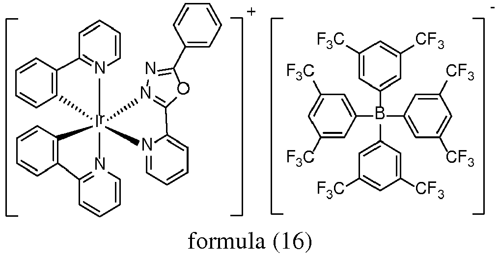
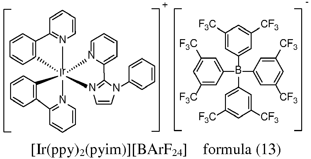
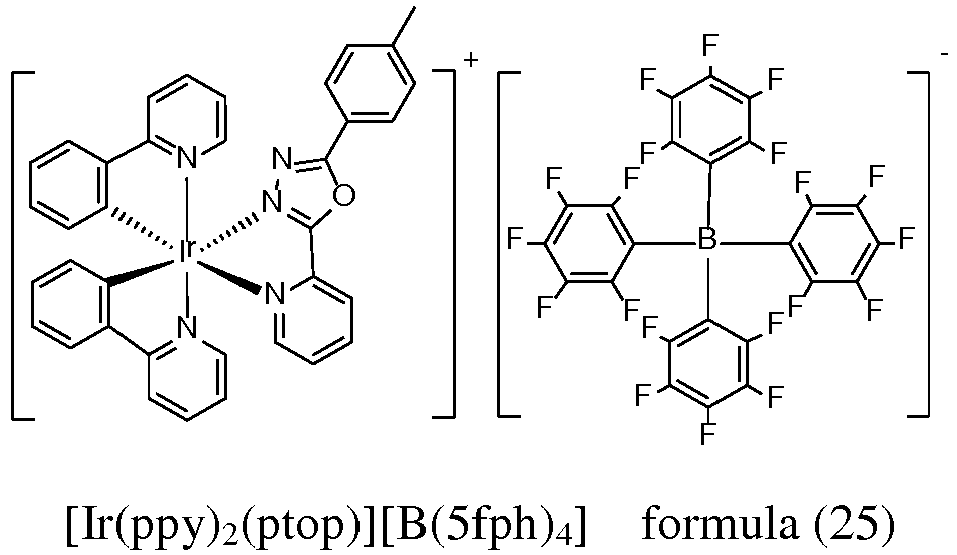
- the depositable ionic complex has a structure shown in the following formulas (11) to (16) and formulas (21) to (26):
- a use of the aforementioned depositable ionic organic functional material in an organic electroluminescent device is provided, wherein, the depositable ionic organic functional material is used as a dye in an organic light-emitting layer of the organic electroluminescent device.
- An organic electroluminescent device which comprises a substrate, and an anode layer, an organic light-emitting functional layer, a cathode layer formed in sequence upon the substrate, wherein the organic light-emitting functional layer comprises a hole transport layer, an organic light-emitting layer and an electron transport layer, and wherein a host material of the organic light-emitting layer is doped with the aforementioned depositable ionic organic functional material.
- Doping concentration of the depositable ionic organic functional material is 2wt%-10wt%.
- the depositable ionic organic functional material is red, yellow, green or blue light emitting material.
- the organic light-emitting layer has a thickness of 10mm-50mm, preferably 10mm-30mm.
- the depositable ionic organic functional material of the present invention has the following advantages: A molecular design strategy for obtaining a depositable ionic organic functional material is provided for the first time by the present invention, wherein a series of depositable ionic Iridium complexes are designed and developed.
- a tetraphenylborate derivative anion which is a counterion with large steric hindrance and good electrical charge dispersion, is introduced into a cationic Iridium complex to replace the hexafluorophosphate anion as mentioned in the background technology, thereby reducing the interactivity between anions and cations.
- the tetraphenylborate derivative anion can increase the electrical charge transport capability, reduce the drive voltage of the device, reduce the energy consumption, and thus effectively reduce the production cost.
- the present invention is simple and easy to carry out and has universality, depositable ionic Iridium complexes as dyes of various colors can be developed accordingly, so as to produce high-efficiency OLEDs emitting blue to red light.
- the present invention provides a depositable ionic organic functional material, wherein the depositable ionic organic functional material has a structure shown in the following formula (1):
- the depositable ionic organic functional material is preferably:
- a use of the aforementioned depositable ionic organic functional material in an organic electroluminescent device is provided.
- the depositable ionic organic functional material is used as a dye in an organic light-emitting layer of the organic electroluminescent device.
- the organic electroluminescent device comprises a substrate 01, and an anode layer 02, an organic light-emitting functional layer, a cathode layer 03 formed in sequence upon the substrate, wherein the organic light-emitting functional layer comprises a hole injection layer 04, a hole transport layer 05, an organic light-emitting layer 06 and an electron transport layer 07, and wherein a host material of the organic light-emitting layer 06 is doped with the aforementioned depositable ionic organic functional material.
- Doping concentration of the depositable ionic organic functional material is 2wt%-10wt%.
- the depositable ionic organic functional material is red, yellow, green or blue light emitting material.
- the organic light-emitting layer has a thickness of 10mm-50mm, preferably 10mm-30mm.
- the anode layer may adopt inorganic material or organic conducting polymer.
- the inorganic material is usually selected from metal oxides such as indium tin oxide (ITO), zinc oxide (ZnO), indium zinc oxide (IZO), and metals having relatively high work function such as gold, copper, silver, and it is preferably ITO.
- the organic conducting polymer is preferably selected from Polythiophene / Polyvinylbenzenesulfonate sodium (hereinafter abbreviated as PEDOT:PSS), and polyaniline (hereinafter abbreviated as PANI).
- the cathode layer usually adopts metals having relatively low work function such as lithium, magnesium, calcium, strontium, aluminum, indium, or their alloys with copper, gold, silver, or the cathode layer is an electrode layer formed by alternately arranged metal and metal fluoride.
- the cathode layer is preferably a mixed electrode of Mg:Ag/Ag.
- the material of the hole transport layer may be selected from aromatic amine type, carbazole type and branched polymer type low molecular material, and is preferably selected from NPB and TCTA.
- the organic electroluminescent device of the present invention there may also be a hole injection layer between the anode layer and the hole transport layer.
- the material of the hole injection layer may adopt, for example, 2,3,6,7,10,11-hexacyanyl-1,4,5,8,9,12-hexaazatriphenylene (HAT-CN), 4,4',4"-tri-(3-methyl-phenyl-aniline)-tri-aniline doped with F4TCNQ, or may adopt copper phthalocyanine (CuPc), or may be a metal oxide such as molybdenum oxide, rhenium oxide.
- the light-emitting material of the organic light-emitting layer 06 may be a fluorescent dye selected from coumarins such as DMQA or C545T, bis-pyrans such as DCJTB or DCM, or may be a metal complex containing lanthanide series or actinide series metal such as Ir, Pt ,Os, Ru, Rh, Pd.
- the fluorescent dye has a doping concentration no higher than 5wt% in the organic light-emitting layer 06, and the phosphorescent dye has a doping concentration no higher than 30wt% in the organic light-emitting layer 06.
- Said doping concentration dye mass / (dye mass + host material mass) ⁇ 100%.
- the host material of the organic light-emitting layer 06 may be selected from materials which are commonly used as a substrate material, such as 4,4'-di-(carbazole-9-yl)-biphenyl (CBP).
- CBP 4,4'-di-(carbazole-9-yl)-biphenyl
- the material of the electron transport layer may adopt a material which is commonly used for an electron transport layer, such as aromatic fused ring compound (e.g. pentacene, perylene) or o-phenanthroline compound (e.g. Bphen, BCP).
- aromatic fused ring compound e.g. pentacene, perylene
- o-phenanthroline compound e.g. Bphen, BCP
- the organic electroluminescent device of the present invention comprises an anode layer 02, a hole transport layer 05, an organic light-emitting layer 06, an electron transport layer 07 and a cathode layer 03 sequentially deposited in a stacked manner upon a substrate 01, which are then encapsulated.
- the substrate may be a glass substrate or a flexible substrate, wherein the flexible substrate may adopt polyester, polyimide compound material, or a thin metal plate.
- the layered stacking and encapsulation may be conducted by using any suitable method known to a person skilled in the art.
- a specific preparation method of the organic electroluminescent device of the present invention is as follows: Firstly, washing a glass substrate with detergent or deionized water, placing the glass substrate under an infrared lamp for drying, and spattering a layer of anode material with a film thickness of 150nm upon the glass substrate.
- Evaporation coating an organic light-emitting layer upon the hole transport layer by using a double source co-evaporation method, wherein the mass percentages of the host material and the dye are controlled by using a film thickness monitor-controller to adjust the film coagulation speed, and the evaporation coated film thickness thereof is 30nm.
- evaporation coating a Mg:Ag layer and a Ag layer in sequence as a cathode layer upon the electron transport layer wherein the Mg:Ag layer is coated by using a double source co-evaporation method, and the mass percentages of Mg and Ag are controlled by using a film thickness monitor-controller to adjust the film coagulation speed, and the evaporation coated film thickness thereof is 150nm; the Ag layer is evaporation coated at a speed of 1.0nm/s, to get a thickness of 50nm.
- Di-chlorine bridged Iridium di-ligand [Ir(dfppy) 2 Cl] 2 (3.100g, 2.55mmol) and pzpy ligand (0.743g, 5.12mmol) is dissolved in 1,2-glycol (60mL). In nitrogen atmosphere, the solution system is refluxed for 12h at 140°C to get a clear bright yellow solution. After cooling to room temperature, Na[BArF 24 ] (4.522g, 5.10mmol) is slowly added to the reaction system with stirring. The reaction product is suction filtrated, washed with CH 2 Cl 2 , and then dried over a night in a 70°C vacuum drying oven.
- the crude product is subsequently passed through silica chromatographic column (200-300 mesh), with CH 2 Cl 2 as the mobile phase, to get the clathrate compound [Ir(dfppy) 2 (pzpy)][BArF 24 ] shown in formula (11) as pale yellow powder (5.283g, 3.34mmol) at a yield of 66%.
- the reactants are [Ir(ppy) 2 Cl] 2 (1.662g, 1.55mmol) and pzpy ligand (0.468g, 3.22mmol), and by going through the same synthesis method as that of Embodiment 2, the clathrate compound [Ir(ppy) 2 (pzpy)][BArF 24 ] shown in formula (12) is obtained as pale yellow powder (3.790g, 2.51mmol) at a yield of 81%.
- the reactants are [Ir(ppy) 2 Cl] 2 (3.064g, 2.86mmol) and pyim ligand (1.255g, 5.67mmol), and by going through the same synthesis method as that of Embodiment 2, the clathrate compound [Ir(ppy) 2 (pyim)][BArF 24 ] shown in formula (13) is obtained as yellow powder (1.024g, 0.77mmol) at a yield of 86%.
- the reactants are [Ir(ppy) 2 Cl] 2 (1.767g, 1.65mmol) and 2,2'-bipyridine ( bpy ) ligand (0.528g, 3.38mmol), and by going through the same synthesis method as that of Embodiment 2, the clathrate compound [Ir(ppy) 2 (bpy)][BArF 24 ] shown in formula (14) is obtained as yellow powder (4.290g, 2.82mmol) at a yield of 86%.
- the reactants are [Ir(ppy) 2 Cl] 2 (1.775g, 1.66mmol) and pop ligand (0.740g, 3.32mmol), and by going through the same synthesis method as that of Embodiment 2, the clathrate compound [Ir(ppy) 2 (pop)][BArF 24 ] shown in formula (16) is obtained as red powder (4.551g, 2.87mmol) at a yield of 87%.
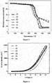
- the clathrate compounds shown in formulas (11) to (16) prepared in Embodiments 2-7 undergo thermogravimetric analysis in N 2 atmosphere, as shown in Figure 1 , it can be seen that the series of Iridium-containing depositable materials with [BArF 24 ] - as a counterion do not have notable mass loss until above 250°C, which indicates this type of materials have a high glass transition temperature and good thermal stability.
- the reactants are [Ir(ppy) 2 Cl] 2 (0.473g, 0.39mmol) and dfpzpy ligand (0.187g, 1.29mmol), and by going through the same synthesis method as that of Embodiment 2, the clathrate compound [Ir(dfppy) 2 (pzpy)][B(5fph) 4 ] shown in formula (21) is obtained as bright yellow powder (0.770g, 0.56mmol) at a yield of 71%.
- the reactants are [Ir(ppy) 2 Cl] 2 (0.578g, 0.54mmol) and pzpy ligand (0.231g, 1.59mmol), and by going through the same synthesis method as that of Embodiment 2, the clathrate compound [Ir(ppy) 2 (pzpy)][B(5fph) 4 ] shown in formula (22) is obtained as yellow powder (1.024g, 0.77mmol) at a yield of 72%.
- the reactants are [Ir(ppy) 2 Cl] 2 (0.569g, 0.53mmol) and pyim ligand (0.233g, 1.05mmol), and by going through the same synthesis method as that of Embodiment 2, the clathrate compound [Ir(ppy) 2 (pyim)][B(5fph) 4 ] shown in formula (23) is obtained as yellow powder (1.024g, 0.77mmol) at a yield of 61%.
- the reactants are [Ir(ppy) 2 Cl] 2 (0.655g, 0.61mmol) and 2,2'-bipyridine ( bpy ) ligand (0.25g, 1.60mmol), and by going through the same synthesis method as that of Embodiment 2, the clathrate compound [Ir(ppy) 2 (bpy)][B(5fph) 4 ] shown in formula (24) is obtained as yellow powder (1.024g, 0.77mmol) at a yield of 65%.
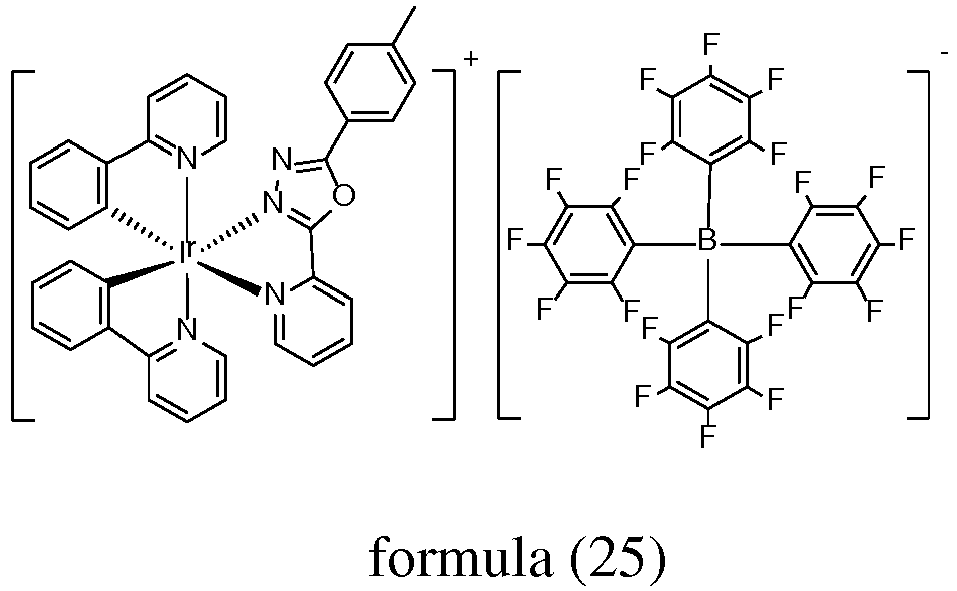
- the reactants are [Ir(ppy) 2 Cl] 2 (1.775g, 1.66mmol) and ptop ligand (0.341g, 1.44mmol), and by going through the same synthesis method as that of Embodiment 2, the clathrate compound [Ir(ppy) 2 (ptop)][B(5fph) 4 ] shown in formula (25) is obtained as red powder (1.65g, 1.16mmol) at a yield of 81%.
- the reactants are [Ir(ppy) 2 Cl] 2 (0.576g, 0.54mmol) and pop ligand (0.243g, 1.09mmol), and by going through the same synthesis method as that of Embodiment 2, the clathrate compound [Ir(ppy) 2 (pop)][BArF 24 ] shown in formula (26) is obtained as red powder (1.024g, 0.77mmol) at a yield of 74%.
- the clathrate compounds shown in formulas (21) to (26) prepared in Embodiments 8-13 undergo thermogravimetric analysis in N 2 atmosphere, as shown in Figure 5 , it can be seen that the series of Iridium-containing depositable materials with [B(5fph) 4 ] - as a counterion do not have notable mass loss until above 320°C, which indicates this type of materials have a high glass transition temperature and good thermal stability.
- Devices 1-6 of this embodiment have the following structure:
- the "x%" before the dye of the devices 1-6 represents a doping concentration of the dye in the organic light-emitting layer. In this embodiment and hereinafter, the doping concentration is measured in wt%.
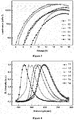
- the current density-voltage spectrogram of the devices 1-6 is shown in Figure 2
- their luminance-voltage spectrogram is shown in Figure 3
- their electroluminescence spectrogram is shown in Figure 4 .
- the devices begin to illuminate at a drive voltage of 4V
- the maximum luminance is as high as 27.1 ⁇ 10 3 cd/m 2
- they can realize light-emitting colors from blue to red.
- the "11, 12, 13, 14, 15, 16" in Figures 2-4 respectively represent the devices corresponding to the compounds shown in formula (11), formula (12), formula (13), formula (14), formula (15), formula (16).
- Devices 7-12 of this embodiment have the following structure:
- the "x%" before the dye of the devices 7-12 represents a doping concentration of the dye in the organic light-emitting layer. In this embodiment and hereinafter, the doping concentration is measured in wt%.
- CzPO 2 : 2% clathrate compound 21 of the structure of the organic light-emitting layer in the first column of the Tables above refers to that the host material CzPO 2 of the organic light-emitting layer is doped with 2wt% of dye, and the dye is [Ir(dfppy) 2 (pzpy)][B(5fph) 4 ] shown in formula (21). And so on for the second to sixth lines.
- the current density-voltage spectrogram of devices 7-12 is shown in Figure 6
- their luminance-voltage spectrogram is shown in Figure 7
- their electroluminescence spectrogram is shown in Figure 8 .
- the devices begin to illuminate at a drive voltage of 4V
- the maximum luminance is as high as 27.1 ⁇ 10 3 cd/m 2
- they can realize light-emitting colors from blue to red.
- the "21, 22, 23, 24, 25, 26" in Figures 6-8 respectively represent the devices corresponding to the compounds shown in formula (21), formula (22), formula (23), formula (24), formula (25), formula (26).
- a device 13 of this embodiment has the following structure:
- a device 14 of this embodiment has the following structure:
- a device 15 of this embodiment has the following structure:
Landscapes
- Chemical & Material Sciences (AREA)
- Organic Chemistry (AREA)
- Engineering & Computer Science (AREA)
- Materials Engineering (AREA)
- Physics & Mathematics (AREA)
- Optics & Photonics (AREA)
- Inorganic Chemistry (AREA)
- Crystallography & Structural Chemistry (AREA)
- Spectroscopy & Molecular Physics (AREA)
- Manufacturing & Machinery (AREA)
- Electroluminescent Light Sources (AREA)
- Pyridine Compounds (AREA)
Abstract


Description
- The present invention relates to the field of organic electroluminescent materials, and in particular relates to a depositable ionic organic functional material which can be used in an organic electroluminescent device, a preparation method thereof and use thereof in the field of organic electroluminescent materials.
- The organic light-emitting layer of an organic electroluminescent device OLED is prepared mainly by using a fully fluorescent material, a fully phosphorescent material, or a mixture of fluorescent material and phosphorescent material. The fluorescent light-emitting material in the prior art is prone to fluorescent quenching, and the device prepared by doping the light-emitting layer with the fluorescent light-emitting material in the prior art is prone to crystallization phenomenon, which leads to reduced service life. And it is difficult to use a phosphorescent light-emitting material to synthesize a stable dark-blue light material.
- In order to solve the above-mentioned problem, cationic complex is developed to be used as light-emitting material. The synthesis conditions of this type of material are mild and easy to carry out, with high yield, and the product is simple to purify; secondly, this type of complex has good redox properties and can increase the stability of the device. However, because ionic material has poor volatilization properties and is not suitable for preparing a device by means of evaporation-deposition, which severely limits the use of this type of material in electronic devices.
- Advanced Functional Materials, 2007, 17, 315 discloses an Iridium complex having a structure shown in the following formula (41), wherein the reported two kinds of depositable ionic complexes adopt an Iridium complex as the cation, and adopts a hexafluorophosphate anion as the counterion. This method has a deficiency of not having universality, i.e. more kinds of depositable ionic complexes cannot be developed according to this route.

- An objective of the present invention is to provide a depositable ionic organic functional material wherein, when the functional material is used as a luminescent dye, the synthesis conditions are mild and easy to carry out, the yield is high, the product is simple to purify, and the functional material can be used in high-efficiency OLEDs emitting blue to red light.
- In order to achieve the above-mentioned objective, the present invention adopts the following technical scheme:
A depositable ionic organic functional material is provided, which has a structure shown in the following formula (1):
- wherein, R is a hydrogen atom, a halogen atom or -CF3;
- R' is a hydrogen atom or a halogen atom;
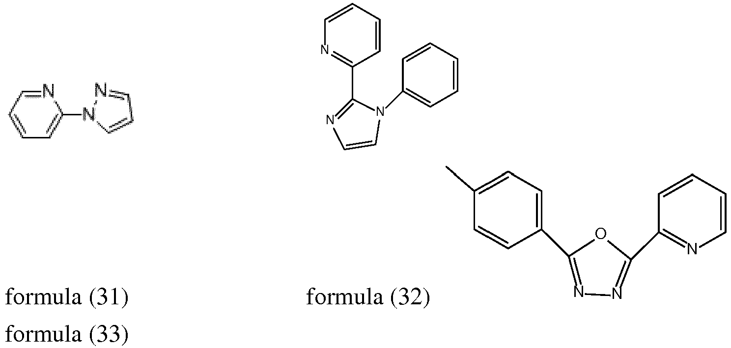
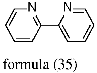
- the N^N ligand is selected from Pzpy shown in the following formula (31) and its derivatives, Pyim shown in the following formula (32), Ptop shown in the following formula (33), Pop shown in the following formula (34), Bpy shown in the following formula (35), and Dfppy shown in the following formula (36):


- Preferable, the depositable ionic complex has a structure shown in the following formulas (11) to (16) and formulas (21) to (26):




- A use of the aforementioned depositable ionic organic functional material in an organic electroluminescent device is provided, wherein, the depositable ionic organic functional material is used as a dye in an organic light-emitting layer of the organic electroluminescent device.
- An organic electroluminescent device is provided, which comprises a substrate, and an anode layer, an organic light-emitting functional layer, a cathode layer formed in sequence upon the substrate, wherein the organic light-emitting functional layer comprises a hole transport layer, an organic light-emitting layer and an electron transport layer, and wherein a host material of the organic light-emitting layer is doped with the aforementioned depositable ionic organic functional material.
- Doping concentration of the depositable ionic organic functional material is 2wt%-10wt%.
- The depositable ionic organic functional material is red, yellow, green or blue light emitting material.
- The organic light-emitting layer has a thickness of 10mm-50mm, preferably 10mm-30mm.
- As compared to the prior art, the depositable ionic organic functional material of the present invention has the following advantages:
A molecular design strategy for obtaining a depositable ionic organic functional material is provided for the first time by the present invention, wherein a series of depositable ionic Iridium complexes are designed and developed. In this type of depositable ionic Iridium complexes, a tetraphenylborate derivative anion, which is a counterion with large steric hindrance and good electrical charge dispersion, is introduced into a cationic Iridium complex to replace the hexafluorophosphate anion as mentioned in the background technology, thereby reducing the interactivity between anions and cations. Furthermore, the tetraphenylborate derivative anion can increase the electrical charge transport capability, reduce the drive voltage of the device, reduce the energy consumption, and thus effectively reduce the production cost. The present invention is simple and easy to carry out and has universality, depositable ionic Iridium complexes as dyes of various colors can be developed accordingly, so as to produce high-efficiency OLEDs emitting blue to red light. -
-
Figure 1 is a thermogravimetric analysis diagram of the complexes shown by the formulas (11) to (16) in a N2 atmosphere; -
Figure 2 is a current density-voltage spectrogram of the devices 1-6 in the application example 1; -
Figure 3 is a luminance-voltage spectrogram of the devices 1-6 in the application example 1; -
Figure 4 is an EL spectrogram of the devices 1-6 in the application example 1; -
Figure 5 is a thermogravimetric analysis diagram of the complexes shown by the formulas (21) to (26) in a N2 atmosphere; -
Figure 6 is a current density-voltage spectrogram of the devices 7-12 in the application example 2; -
Figure 7 is a luminance-voltage spectrogram of the devices 7-12 in the application example 2; -
Figure 8 is an EL spectrogram of the devices 7-12 in the application example 2; -
Figure 9 is a structural schematic diagram of the organic electroluminescent device;
wherein,- 01- substrate,
- 02- anode layer
- 03- cathode layer
- 04- hole injection layer
- 05- hole transport layer
- 06- organic light-emitting layer
- 07- electron transport layer
- The present invention is further described hereinafter by illustrating specific embodiments.
- The present invention can be implemented in many different forms, and should not be interpreted to be limited to the embodiments described herein. On the contrary, by providing these embodiments, the present disclosure is made complete and thorough, and the inventive concept of the present invention is sufficiently conveyed to those skilled in the art, wherein the present invention is defined by the Claims. In the accompanying drawings, for the sake of clarity, dimensions and relative sizes of layers and areas might be exaggerated. It should be understood that, when one element such as a layer, an area or a substrate is described as "formed on" or "configured on" another element, this one element may be configured directly upon that another element, or there may exists intermediate element(s). On the contrary, when one element is described as "directly formed upon" or "directly configured upon" another element, there exists no intermediate element.
- The present invention provides a depositable ionic organic functional material, wherein the depositable ionic organic functional material has a structure shown in the following formula (1):

- wherein, R is a hydrogen atom, a halogen atom or -CF3;
- R' is a hydrogen atom or a halogen atom;
- N^N ligand is selected from Pzpy shown in the following formula (31) and its derivatives, Pyim shown in the following formula (32), Ptop shown in the following formula (33), Pop shown in the following formula (34), Bpy shown in the following formula (35), and Dfppy shown in the following formula (36):


- The depositable ionic organic functional material is preferably:





- A use of the aforementioned depositable ionic organic functional material in an organic electroluminescent device is provided.
- In the above-mentioned use, the depositable ionic organic functional material is used as a dye in an organic light-emitting layer of the organic electroluminescent device.
- As shown in
Figure 9 , the organic electroluminescent device comprises asubstrate 01, and ananode layer 02, an organic light-emitting functional layer, acathode layer 03 formed in sequence upon the substrate, wherein the organic light-emitting functional layer comprises ahole injection layer 04, ahole transport layer 05, an organic light-emittinglayer 06 and anelectron transport layer 07, and wherein a host material of the organic light-emittinglayer 06 is doped with the aforementioned depositable ionic organic functional material. - Doping concentration of the depositable ionic organic functional material is 2wt%-10wt%.
- The depositable ionic organic functional material is red, yellow, green or blue light emitting material.
- The organic light-emitting layer has a thickness of 10mm-50mm, preferably 10mm-30mm.
- If not particularly described otherwise, the respective layers of the device in the present invention are made of the following materials:
The anode layer may adopt inorganic material or organic conducting polymer. The inorganic material is usually selected from metal oxides such as indium tin oxide (ITO), zinc oxide (ZnO), indium zinc oxide (IZO), and metals having relatively high work function such as gold, copper, silver, and it is preferably ITO. The organic conducting polymer is preferably selected from Polythiophene / Polyvinylbenzenesulfonate sodium (hereinafter abbreviated as PEDOT:PSS), and polyaniline (hereinafter abbreviated as PANI). - The cathode layer usually adopts metals having relatively low work function such as lithium, magnesium, calcium, strontium, aluminum, indium, or their alloys with copper, gold, silver, or the cathode layer is an electrode layer formed by alternately arranged metal and metal fluoride. In the present invention, the cathode layer is preferably a mixed electrode of Mg:Ag/Ag.
- The material of the hole transport layer may be selected from aromatic amine type, carbazole type and branched polymer type low molecular material, and is preferably selected from NPB and TCTA.
- In the organic electroluminescent device of the present invention, there may also be a hole injection layer between the anode layer and the hole transport layer. The material of the hole injection layer may adopt, for example, 2,3,6,7,10,11-hexacyanyl-1,4,5,8,9,12-hexaazatriphenylene (HAT-CN), 4,4',4"-tri-(3-methyl-phenyl-aniline)-tri-aniline doped with F4TCNQ, or may adopt copper phthalocyanine (CuPc), or may be a metal oxide such as molybdenum oxide, rhenium oxide.
- The light-emitting material of the organic light-emitting
layer 06 may be a fluorescent dye selected from coumarins such as DMQA or C545T, bis-pyrans such as DCJTB or DCM, or may be a metal complex containing lanthanide series or actinide series metal such as Ir, Pt ,Os, Ru, Rh, Pd. - The fluorescent dye has a doping concentration no higher than 5wt% in the organic light-emitting
layer 06, and the phosphorescent dye has a doping concentration no higher than 30wt% in the organic light-emittinglayer 06. Said doping concentration = dye mass / (dye mass + host material mass) × 100%. - The host material of the organic light-emitting
layer 06 may be selected from materials which are commonly used as a substrate material, such as 4,4'-di-(carbazole-9-yl)-biphenyl (CBP). - The material of the electron transport layer may adopt a material which is commonly used for an electron transport layer, such as aromatic fused ring compound (e.g. pentacene, perylene) or o-phenanthroline compound (e.g. Bphen, BCP).
- The organic electroluminescent device of the present invention comprises an
anode layer 02, ahole transport layer 05, an organic light-emittinglayer 06, anelectron transport layer 07 and acathode layer 03 sequentially deposited in a stacked manner upon asubstrate 01, which are then encapsulated. - The substrate may be a glass substrate or a flexible substrate, wherein the flexible substrate may adopt polyester, polyimide compound material, or a thin metal plate. The layered stacking and encapsulation may be conducted by using any suitable method known to a person skilled in the art.
- A specific preparation method of the organic electroluminescent device of the present invention is as follows:
Firstly, washing a glass substrate with detergent or deionized water, placing the glass substrate under an infrared lamp for drying, and spattering a layer of anode material with a film thickness of 150nm upon the glass substrate. - Then, placing the above-mentioned glass substrate with anode layer into a vacuum chamber, vacuumizing to 1×10⁻⁴ Pa, continuing to evaporation coating NPB as a hole transport layer upon the anode layer, at a film coagulation speed of 0.1nm/s, to get an evaporation coated film thickness of 40nm.
- Evaporation coating an organic light-emitting layer upon the hole transport layer by using a double source co-evaporation method, wherein the mass percentages of the host material and the dye are controlled by using a film thickness monitor-controller to adjust the film coagulation speed, and the evaporation coated film thickness thereof is 30nm.
- Continuing to evaporation coating a layer of TPBi material as a second electron transport layer upon the organic light-emitting layer, at a deposition rate of 0.1nm/s, to get an evaporation coated film total thickness of 30nm.
- Finally, evaporation coating a Mg:Ag layer and a Ag layer in sequence as a cathode layer upon the electron transport layer, wherein the Mg:Ag layer is coated by using a double source co-evaporation method, and the mass percentages of Mg and Ag are controlled by using a film thickness monitor-controller to adjust the film coagulation speed, and the evaporation coated film thickness thereof is 150nm; the Ag layer is evaporation coated at a speed of 1.0nm/s, to get a thickness of 50nm.
- The synthesis routes of the N^N ligand Pzpy, Pyim, Ptop and Pop in the complexes are as follows:
- See details in He, L., et al., Adv. Funct. Mater. 18, 2123-2131 (2008 ).

- See details in He, L., et al., Adv. Funct. Mater. 19, 2950-2960 (2009 ).

- See details in Zhang, J., et al. Adv. Funct. Mater. 23, 4667-4677 (2013 ).

-

- Di-chlorine bridged Iridium di-ligand [Ir(dfppy)2Cl]2 (3.100g, 2.55mmol) and pzpy ligand (0.743g, 5.12mmol) is dissolved in 1,2-glycol (60mL). In nitrogen atmosphere, the solution system is refluxed for 12h at 140°C to get a clear bright yellow solution. After cooling to room temperature, Na[BArF24] (4.522g, 5.10mmol) is slowly added to the reaction system with stirring. The reaction product is suction filtrated, washed with CH2Cl2, and then dried over a night in a 70°C vacuum drying oven. The crude product is subsequently passed through silica chromatographic column (200-300 mesh), with CH2Cl2 as the mobile phase, to get the clathrate compound [Ir(dfppy)2(pzpy)][BArF24] shown in formula (11) as pale yellow powder (5.283g, 3.34mmol) at a yield of 66%.
1H-NMR (600 MHz, DMSO-d6): δ 9.34 (d, J = 3.1 Hz, 1H), 8.55 (d, J = 8.5 Hz, 1H), 8.40-8.36 (m, 1H), 8.30 (d, J = 7.3 Hz, 2H), 8.07 (t, J = 6.3 Hz, 2H), 7.84 (d, J = 5.1 Hz, 1H), 7.78 (d, J = 5.8 Hz, 1H), 7.73 (s, 4H), 7.63 (s, 8H), 7.56 (t, J = 5.4 Hz, 2H), 7.32 (t, J = 6.7 Hz, 1H), 7.29 (t, J = 6.7 Hz, 1H), 7.01-6.91 (m, 2H), 5.65 (d, J = 2.3 Hz, 1H), 5.64 (d, J = 2.3 Hz, 1H), 5.62 (d, J = 2.3 Hz, 1H), 5.60 (d, J = 2.3 Hz, 1H); 19F-NMR (600 MHz, DMSO-d6): δ -61.68 (s, 24F), -106.51 (s, 1F), -107.12 (s, 1F), -108.67 (s, 1F), -109.29 (s, 1F); MS (ESI) [m/z]: [M-BArF24]+ calcd for C30H19F4IrN5, 718.12; found, 718.39; [M-Ir(dfppy)2(pzpy)]- calcd for C32H12BF24, 863.06; found, 863.35.
- The reactants are [Ir(ppy)2Cl]2 (1.662g, 1.55mmol) and pzpy ligand (0.468g, 3.22mmol), and by going through the same synthesis method as that of Embodiment 2, the clathrate compound [Ir(ppy)2(pzpy)][BArF24] shown in formula (12) is obtained as pale yellow powder (3.790g, 2.51mmol) at a yield of 81%.
1H-NMR (600 MHz, DMSO-d6): δ 9.30 (d, J = 3.0 Hz, 1H), 8.53 (d, J = 8.5 Hz, 1H), 8.35-8.30 (m, 1H), 8.26 (dd, J = 8.0 Hz, 3.9 Hz, 2H), 7.95 (ddd, J = 7.7 Hz, 3.2 Hz, 1.9 Hz, 2H), 7.89 (dd, J = 12.6 Hz, 7.8 Hz, 2H), 7.77 (d, J = 5.7 Hz, 1H), 7.71 (d, J = 5.3 Hz, 1H), 7.68 (s, 4H), 7.65 (d, J = 5.6 Hz, 1H), 7.61 (s, 8H), 7.55-7.51 (m, 1H), 7.28 (d, J = 1.9 Hz, 1H), 7.22 (t, J = 6.7 Hz, 1H), 7.18 (t, J = 6.6 Hz, 1H), 7.01 (t, J = 8.0 Hz, 1H), 6.98 (t, J = 7.5 Hz, 1H), 6.91-6.87 (m, 2H), 6.84 (t, J = 7.4 Hz, 1h), 6.19 (dd, J = 9.6 Hz, 7.9 Hz, 2H); 19F-NMR (600 MHz, DMSO-d6): δ -61.74 (s, 24F); MS (ESI) [m/z]: [M-BArF24]+ calcd for C30H23IrN5, 646.16; found, 646.16; [M-Ir(ppy)2(pzpy)]- calcd for C32H12BF24, 863.06; found, 863.06.
- The reactants are [Ir(ppy)2Cl]2 (3.064g, 2.86mmol) and pyim ligand (1.255g, 5.67mmol), and by going through the same synthesis method as that of Embodiment 2, the clathrate compound [Ir(ppy)2(pyim)][BArF24] shown in formula (13) is obtained as yellow powder (1.024g, 0.77mmol) at a yield of 86%.
1H-NMR (600 MHz, DMSO-d6): δ 8.25 (t, J = 8.6 Hz, 2H), 7.98-7.87 (m, 8H), 7.86 (d, J = 1.4 Hz, 1H), 7.83 (d, J = 5.4 Hz, 1H), 7.73 (d, J = 4.9 Hz, 4H), 7.68 (s, 4H), 7.62 (s, 8H), 7.51-7.47 (m, 1H), 7.28-7.25 (m, 1H), 7.25-7.20 (m, 1H), 7.02-6.95 (m, 2H), 6.93 (d, J = 8.3 Hz, 1H), 6.91-6.84 (m, 2H), 6.64 (d, J = 1.4 Hz, 1H), 6.23 (dd, J = 9.4, 8.2 Hz, 2H); 19F-NMR (600 MHz, DMSO-d6): δ -61.12 (s, 24F); MS (ESI) [m/z]: [M-BArF24]+ calcd for C36H27IrN5, 722.19; found, 722.19; [M-Ir(ppy)2(pyim)]- calcd for C32H12BF24, 863.06; found, 863.07.
- The reactants are [Ir(ppy)2Cl]2 (1.767g, 1.65mmol) and 2,2'-bipyridine (bpy) ligand (0.528g, 3.38mmol), and by going through the same synthesis method as that of Embodiment 2, the clathrate compound [Ir(ppy)2(bpy)][BArF24] shown in formula (14) is obtained as yellow powder (4.290g, 2.82mmol) at a yield of 86%.
1H-NMR (600 MHz, DMSO-d6): δ 8.89 (d, J = 8.2 Hz, 2H), 8.27 (t, J = 7.2 Hz, 4H), 7.95-7.90 (m, 4H), 7.88 (d, J = 4.7 Hz, 2H), 7.71 (s, 4H), 7.69 (s, 2H), 7.63 (s, 2H), 7.62 (s, 8H), 7.16 (t, J = 6.0 Hz, 2H), 7.03 (dd, J = 12.6 Hz, 5.5 Hz, 2H), 6.90 (t, J = 7.5 Hz, 2H), 6.20 (d, J = 7.2 Hz, 2H); 19F-NMR (600 MHz, DMSO-d6): δ -61.74 (s, 24F); MS (ESI) [m/z]: [M-BArF24]+ calcd for C32H24IrN4, 657.16; found, 657.16; [M-Ir(ppy)2(bpy)]- calcd for C32H12BF24, 863.06; found, 863.06.
- The reactants are [Ir(ppy)2Cl]2 (1.786g, 1.67mmol) and ptop ligand (0.798g, 3.36mmol), which are dissolved in methanol / CH2Cl2 (v/v = 60 : 60 mL), and the rest of the synthesis method is the same as that of Embodiment 2, thereby obtaining the clathrate compound [Ir(ppy)2(ptop)][BArF24] shown in formula (15) as red powder (4.131g, 2.58mmol) at a yield of 77%.
1H-NMR (600 MHz, DMSO-d6): δ 8.66 (d, J = 7.8 Hz, 1H), 8.37 (t, J = 7.4 Hz, 1H), 8.26 (d, J = 6.0 Hz, 1H), 8.22 (d, J = 8.2 Hz, 2H), 8.01 (d, J = 8.1 Hz, 2H), 7.93 (t, J = 7.8 Hz, 2H), 7.88 (d, J = 7.6 Hz, 1H), 7.82 (dd, J = 5.9 Hz, 1H), 7.69 (s, 4H), 7.63 (d, J = 5.9 Hz, 1H), 7.60 (s, 8H), 7.44 (d, J = 8.0 Hz, 2H), 7.18 (t, J = 6.6 Hz, 2H), 7.01 (dd, J = 9.8 Hz, 4.9 Hz, 1H), 6.94 (t, J = 7.4 Hz, 1H), 6.89 (t, J = 7.3 Hz, 1H), 6.81 (t, J = 7.1 Hz, 1H), 6.11 (dd, J = 13.1 Hz, 7.6 Hz, 2H), 1.22 (s, 3H); 19F-NMR (600 MHz, DMSO-d6): δ -61.51 (s, 24F); MS (ESI) [m/z]: [M-BArF24]+ calcd for C36H27IrN5O, 738.18; found, 738.18; [M-Ir(ppy)2(ptop)]-calcd for C32H12BF24, 863.06; found, 863.06.
- The reactants are [Ir(ppy)2Cl]2 (1.775g, 1.66mmol) and pop ligand (0.740g, 3.32mmol), and by going through the same synthesis method as that of Embodiment 2, the clathrate compound [Ir(ppy)2(pop)][BArF24] shown in formula (16) is obtained as red powder (4.551g, 2.87mmol) at a yield of 87%.
1H-NMR (600 MHz, DMSO-d6): δ 8.68 (d, J = 7.7 Hz, 1H), 8.38 (td, J = 7.8 Hz, 2.1 Hz, 1H), 8.26 (d, J = 5.5 Hz, 1H), 8.22 (d, J = 8.5 Hz, 2H), 8.14-8.10 (m, 2H), 7.94 (t, J = 7.8 Hz, 2H), 7.88 (d, J = 8.7 Hz, 1H), 7.86-7.81 (m, 3H), 7.72 (d, J = 7.4 Hz, 1H), 7.69 (s, 4H), 7.63 (dd, J = 13.5 Hz, 6.1 Hz, 3H), 7.60 (s, 8H), 7.18 (dt, J = 6.0 Hz, 4.7 Hz, 2H), 7.01 (t, J = 7.6 Hz, 1H), 6.94 (t, J = 7.6 Hz, 1H), 6.89 (dd, J = 8.1 Hz, 7.1 Hz, 1H), 6.81 (t, J = 7.5 Hz, 1H), 6.11 (dd, J = 11.9 Hz, 7.5 Hz, 2H); 19F-NMR (600 MHz, DMSO-d6): δ -61.60 (s, 24F); MS (ESI) [m/z]: [M-BArF24]+ calcd for C35H25IrN5O, 724.17; found, 724.16; [M-Ir(ppy)2(pop)]- calcd for C32H12BF24, 863.06; found, 863.06.
- The clathrate compounds shown in formulas (11) to (16) prepared in Embodiments 2-7 undergo thermogravimetric analysis in N2 atmosphere, as shown in
Figure 1 , it can be seen that the series of Iridium-containing depositable materials with [BArF24]- as a counterion do not have notable mass loss until above 250°C, which indicates this type of materials have a high glass transition temperature and good thermal stability. - The reactants are [Ir(ppy)2Cl]2 (0.473g, 0.39mmol) and dfpzpy ligand (0.187g, 1.29mmol), and by going through the same synthesis method as that of Embodiment 2, the clathrate compound [Ir(dfppy)2(pzpy)][B(5fph)4] shown in formula (21) is obtained as bright yellow powder (0.770g, 0.56mmol) at a yield of 71%.
1H NMR (600 MHz, DMSO-d6, δ) 9.34 (dd, J = 2.9 Hz, 1.4 Hz, 1H), 8.55 (d, J = 8.5 Hz, 1H), 8.39-8.36 (m, 1H), 8.30 (d, J = 6.3 Hz, 2H), 8.09-8.04 (m, 2H), 7.84 (dd, J = 6.8 Hz, 6.4 Hz, 1H), 7.78 (d, J = 5.8 Hz, 1H), 7.75 (d, J = 5.7 Hz, 1H), 7.57-7.53 (m, 2H), 7.34-7.23 (m, 3H), 7.19-7.13 (m, 1H), 7.00-6.91 (m, 3H). 19F NMR (600 MHz, DMSO-d6, δ) -106.45 (s, 1F), -107.10 (s, 1F), -108.60 (s, 1F), -109.25 (s, 1F), -132.23 (s, 8F), -161.17 (s, 4F), -165.71 (s, 8F). MS (ESI) [m/z]: 718.40 [M-B(5fph)4]+, 679.28 [M-Ir(dfppy)2(pzpy)]-. Anal. Calcd. for C54H19BF24IrN5: C, 46.43; H, 1.37; N, 5.01. Found: C, 45.84; H, 1.50; N, 4.95.
- The reactants are [Ir(ppy)2Cl]2 (0.578g, 0.54mmol) and pzpy ligand (0.231g, 1.59mmol), and by going through the same synthesis method as that of Embodiment 2, the clathrate compound [Ir(ppy)2(pzpy)][B(5fph)4] shown in formula (22) is obtained as yellow powder (1.024g, 0.77mmol) at a yield of 72%.
1H NMR (600 MHz, DMSO-d6, δ) 9.28 (d, J = 2.8 Hz, 1H), 8.51 (d, J = 8.3 Hz, 1H), 8.31 (t, J = 8.0 Hz, 1H), 8.28-8.21 (m, 2H), 7.94 (d, J = 7.8 Hz, 2H), 7.88 (dd, J = 12.3, 7.8 Hz, 2H), 7.75 (d, J = 5.7 Hz, 1H), 7.70 (d, J = 5.6 Hz, 1H), 7.64 (d, J = 5.5 Hz, 1H), 7.54-7.50 (m, 1H), 7.27 (s, 1H), 7.25-7.15 (m, 2H), 6.99 (dt, J = 19.2, 7.5 Hz, 2H), 6.93-6.80 (m, 3H), 6.22-6.15 (m, 2H). 19F NMR (600 MHz, DMSO-d6, δ) -132.35 (s, 8F), -161.20 (s, 4F), -165.81 (s, 8F). MS (ESI) [m/z]: 646.40 [M-B(5fph)4]+, 679.22 [M-Ir(ppy)2(pzpy)]-. Anal. Calcd. for C54H23BF20IrN5: C, 48.96; H, 1.75; N, 5.29. Found: C, 49.37; H, 2.00; N, 5.46.
- The reactants are [Ir(ppy)2Cl]2 (0.569g, 0.53mmol) and pyim ligand (0.233g, 1.05mmol), and by going through the same synthesis method as that of Embodiment 2, the clathrate compound [Ir(ppy)2(pyim)][B(5fph)4] shown in formula (23) is obtained as yellow powder (1.024g, 0.77mmol) at a yield of 61%.
1H NMR (600 MHz, DMSO-d6, δ) 8.24 (t, J = 8.9 Hz, 2H), 7.97-7.92 (m, 4H), 7.89 (dd, J = 13.1, 6.8 Hz, 4H), 7.85 (d, J = 1.1 Hz, 1H), 7.83 (d, J = 5.3 Hz, 1H), 7.74 (d, J = 5.7 Hz, 4H), 7.48 (dd, J = 7.0, 6.2 Hz, 1H), 7.26 (dd, J = 9.7, 3.5 Hz, 1H), 7.21 (t, J = 6.6 Hz, 1H), 7.01-6.92 (m, 3H), 6.88 (dd, J = 12.5, 5.0 Hz, 1H), 6.85 (t, J = 7.4 Hz, 1H), 6.64 (d, J = 1.3 Hz, 1H), 6.24 (dd, J = 9.9, 7.8 Hz, 2H). 19F NMR (600 MHz, DMSO-d6, δ) -132.36 (s, 8F), -161.18 (s, 4F), -166.20 (s, 8F). MS (ESI) [m/z]: 722.19 [M-B(5fph)4]+, 678.98 [M-Ir(ppy)2(pyim)]-. Anal. Calcd. for C60H27BF20IrN5: C, 51.44; H, 1.94; N, 5.00. Found: C, 51.79; H, 2.27; N, 4.87.
- The reactants are [Ir(ppy)2Cl]2 (0.655g, 0.61mmol) and 2,2'-bipyridine (bpy) ligand (0.25g, 1.60mmol), and by going through the same synthesis method as that of Embodiment 2, the clathrate compound [Ir(ppy)2(bpy)][B(5fph)4] shown in formula (24) is obtained as yellow powder (1.024g, 0.77mmol) at a yield of 65%.
1H NMR (600 MHz, DMSO-d6, δ) 8.89 (d, J = 8.4 Hz, 2H), 8.28 (dd, J = 11.0, 4.8 Hz, 4H), 7.96-7.91 (m, 4H), 7.89-7.87 (m, 2H), 7.70 (ddd, J = 7.6, 5.5, 1.1 Hz, 2H), 7.62 (dd, J = 5.8, 0.7 Hz, 2H), 7.18-7.15 (m, 2H), 7.05-7.00 (m, 2H), 6.91 (td, J = 7.5, 1.3 Hz, 2H), 6.20 (dd, J = 7.6, 0.6 Hz, 2H). MS (ESI) [m/z]: 657.16 [M-B(5fph)4]+, 678.98 [M-Ir(ppy)2(bpy)]-. Anal. Calcd. for C56H24BF20IrN4: C, 50.35; H, 1.81; N, 4.19. Found: C, 50.83; H, 2.24; N, 4.18.
- The reactants are [Ir(ppy)2Cl]2 (1.775g, 1.66mmol) and ptop ligand (0.341g, 1.44mmol), and by going through the same synthesis method as that of Embodiment 2, the clathrate compound [Ir(ppy)2(ptop)][B(5fph)4] shown in formula (25) is obtained as red powder (1.65g, 1.16mmol) at a yield of 81%.
1H NMR (600 MHz, DMSO-d6, δ) 8.71 (d, J = 7.8 Hz, 1H), 8.43 (td, J = 7.8 Hz, 1.9 Hz, 1H), 8.32-8.30 (m, 1H), 8.29-8.26 (m, 2H), 8.07 (d, J = 8.2 Hz, 2H), 8.01-7.97 (m, 2H), 7.93 (d, J = 7.3 Hz, 1H), 7.87 (ddd, J = 6.8 Hz, 5.5 Hz, 2.8 Hz, 3H), 7.69 (d, J = 5.8 Hz, 3H), 7.49 (d, J = 8.0 Hz, 1H), 7.25-7.21 (m, 2H), 7.08-7.04 (m, 1H), 7.01-6.97 (m, 1H), 6.94 (td, J = 7.5 Hz, 1.2 Hz, 1H), 6.86 (td, J = 7.5 Hz, 1.2 Hz, 1H), 6.16 (dd, J = 12.9 Hz, 7.0 Hz, 1H), 2.53 (dt, J = 3.6 Hz, 1.8 Hz, 3H). 19F NMR (600 MHz, DMSO-d6, δ) -133.28 (s, 8F), -161.68 (s, 4F), -165.84 (s, 8F). MS (ESI) [m/z]: 738.18 [M-B(5fph)4]+, 678.97 [M-Ir(ppy)2(ptop)]-. Anal. Calcd. for C60H27BF20IrN5O: C, 50.86; H, 1.92; N, 4.94. Found: C, 51.93; H, 1.83; N, 4.98.
- The reactants are [Ir(ppy)2Cl]2 (0.576g, 0.54mmol) and pop ligand (0.243g, 1.09mmol), and by going through the same synthesis method as that of Embodiment 2, the clathrate compound [Ir(ppy)2(pop)][BArF24] shown in formula (26) is obtained as red powder (1.024g, 0.77mmol) at a yield of 74%.
1H NMR (600 MHz, DMSO-d6, δ) 8.73 (d, J = 7.7 Hz, 1H), 8.43 (td, J = 7.7 Hz, 1.6 Hz, 1H), 8.32 (d, J = 5.2 Hz, 1H), 8.27 (d, J = 8.0 Hz, 2H), 8.18 (d, J = 7.3 Hz, 2H), 7.99 (t, J = 7.8 Hz, 2H), 7.93 (d, J = 7.6 Hz, 1H), 7.91-7.86 (m, 3H), 7.76 (t, J = 7.5 Hz, 1H), 7.69 (dd, J = 15.8 Hz, 7.5 Hz, 3H), 7.23 (ddd, J = 6.0 Hz, 4.5 Hz, 2.2 Hz, 2H), 7.06 (dd, J = 9.7 Hz, 5.3 Hz, 1H), 6.99 (t, J = 7.5 Hz, 1H), 6.94 (t, J = 7.5 Hz, 1H), 6.86 (t, J = 7.4 Hz, 1H), 6.17 (dd, J = 12.0 Hz, 7.6 Hz, 2H). 19F NMR (600 MHz, DMSO-d6, δ) -133.30 (s, 8F), -161.68 (s, 4F), -166.65 (s, 8F). MS (ESI) [m/z]: 724.17 [M-B(5fph)4]+, 678.97 [M-Ir(ppy)2(pop)]-. Anal. Calcd. for C59H25BF20IrN5O: C, 50.51; H, 1.80; N, 4.99. Found: C, 51.88; H, 1.92; N, 4.98.
- The clathrate compounds shown in formulas (21) to (26) prepared in Embodiments 8-13 undergo thermogravimetric analysis in N2 atmosphere, as shown in
Figure 5 , it can be seen that the series of Iridium-containing depositable materials with [B(5fph)4]- as a counterion do not have notable mass loss until above 320°C, which indicates this type of materials have a high glass transition temperature and good thermal stability. - Devices 1-6 of this embodiment have the following structure:
- ITO / NPB (40nm) / host material : x% dye (20nm) / TPBi (30nm) / Mg : Ag (150nm) / Ag (50nm)
- The "x%" before the dye of the devices 1-6 represents a doping concentration of the dye in the organic light-emitting layer. In this embodiment and hereinafter, the doping concentration is measured in wt%.
Table 1 Performance of OLED devices made with clathrate compounds 11-16 Structure of the organic light-emitting layer PL wavelength Current efficiency Luminance EL wavelength CIE λ [nm]b η max [cd A-1] B max [cd m-2] λ [nm]b (x,y)d CzPO2: 2 % clathrate compound 11452,481 1.3 6.0×10³ 446 (0.16, 0.12) 26DCzPPy : 8 % clathrate compound 12473,502 3.0 11.9×10³ 476,501 (0.20, 0.37) DIC-TRZ : 4 % clathrate compound 13527 16.3 >27.1×10³ 532 (0.36, 0.57) DIC-TRZ : 2 % clathrate compound 14554 22.6 >27.1×10³ 551 (0.42, 0.54) DIC-TRZ : 10 % clathrate compound 15597 7.1 16.3×10³ 588 (0.51, 0.46) DIC-TRZ : 6 % clathrate compound 16597 5.1 11.1×10³ 594 (0.52, 0.46) - In table 1:
- The
clathrate compound 11 refers to [Ir(dfppy)2(pzpy)][BArF24] shown in formula (11), and the corresponding device serial number is 1; - The
clathrate compound 12 refers to [Ir(ppy)2(pzpy)][BArF24] shown in formula (12), and the corresponding device serial number is 2; - The
clathrate compound 13 refers to [Ir(ppy)2(pyim)][BArF24] shown in formula (13), and the corresponding device serial number is 3; - The
clathrate compound 14 refers to [Ir(ppy)2(bpy)][BArF24] shown in formula (14), and the corresponding device serial number is 4; - The
clathrate compound 15 refers to [Ir(ppy)2(ptop)][BArF24] shown in formula (15), and the corresponding device serial number is 5; - The
clathrate compound 16 refers to [Ir(ppy)2(pop)][BArF24] shown in formula (16), and the corresponding device serial number is 6. - The current density-voltage spectrogram of the devices 1-6 is shown in
Figure 2 , their luminance-voltage spectrogram is shown inFigure 3 , their electroluminescence spectrogram is shown inFigure 4 . As seen fromFigures 2-4 , the devices begin to illuminate at a drive voltage of 4V, the maximum luminance is as high as 27.1 × 10³cd/m2, and as seen from the electroluminescence spectrogram, they can realize light-emitting colors from blue to red. The "11, 12, 13, 14, 15, 16" inFigures 2-4 respectively represent the devices corresponding to the compounds shown in formula (11), formula (12), formula (13), formula (14), formula (15), formula (16). - Devices 7-12 of this embodiment have the following structure:
- ITO / NPB (40nm) / host material : x% dye (20nm) / TPBi (30nm) / Mg : Ag (150nm) / Ag (50nm)
- The "x%" before the dye of the devices 7-12 represents a doping concentration of the dye in the organic light-emitting layer. In this embodiment and hereinafter, the doping concentration is measured in wt%.
Table 2 Performance of OLED devices made with clathrate compounds 21-26 Structure of the organic light-emitting layer PL wavelength Current efficiency Luminance EL wavelength CIE λ [nm]b η max [cd A-1] B max [cd m-2] λ [nm]b (x,y)d CzPO2 : 8 % clathrate compound 21452,480 1.5 5.7×10³ 452 (0.18, 0.19) 26DCzPPy : 6 % clathrate compound 22476,503 6.7 8.2×10³ 506 (0.25, 0.47) DIC-TRZ : 6 % clathrate compound 23531 15.3 >27.1×10³ 532 (0.35, 0.57) DIC-TRZ : 8 % clathrate compound 24555 24.3 >27.1×10³ 550 (0.42, 0.54) DIC-TRZ : 4 % clathrate compound 25599 4.5 22.1×10³ 588 (0.51,0.47) DIC-TRZ : 6 % clathrate compound 26599 4.5 19.4×10³ 596 (0.52, 0.46) - In table 2:
- The
clathrate compound 21 refers to [Ir(dfppy)2(pzpy)][B(5fph)4] shown in formula (21), and the corresponding device serial number is 7; - The
clathrate compound 22 refers to [Ir(ppy)2(pzpy)][B(5fph)4] shown in formula (22), and the corresponding device serial number is 8; - The
clathrate compound 23 refers to [Ir(ppy)2(pyim)][B(5fph)4] shown in formula (23), and the corresponding device serial number is 9; - The
clathrate compound 24 refers to [Ir(ppy)2(bpy)][B(5fph)4] shown in formula (24), and the corresponding device serial number is 10; - The
clathrate compound 25 refers to [Ir(ppy)2(ptop)][B(5fph)4] shown in formula (25), and the corresponding device serial number is 11; - The
clathrate compound 26 refers to [Ir(ppy)2(pop)][BArF24] shown in formula (26), and the corresponding device serial number is 12. - "CzPO2 : 2
% clathrate compound 21" of the structure of the organic light-emitting layer in the first column of the Tables above refers to that the host material CzPO2 of the organic light-emitting layer is doped with 2wt% of dye, and the dye is [Ir(dfppy)2(pzpy)][B(5fph)4] shown in formula (21). And so on for the second to sixth lines. - The current density-voltage spectrogram of devices 7-12 is shown in
Figure 6 , their luminance-voltage spectrogram is shown inFigure 7 , their electroluminescence spectrogram is shown inFigure 8 . As seen fromFigures 6-8 , the devices begin to illuminate at a drive voltage of 4V, the maximum luminance is as high as 27.1 × 10³cd/m2, and as seen from the electroluminescence spectrogram, they can realize light-emitting colors from blue to red. The "21, 22, 23, 24, 25, 26" inFigures 6-8 respectively represent the devices corresponding to the compounds shown in formula (21), formula (22), formula (23), formula (24), formula (25), formula (26). - A
device 13 of this embodiment has the following structure: - ITO / NPB (40nm) / host material: 4% dye (50nm) / TPBi (30nm) / Mg : Ag (150nm) / Ag (50nm)
- A
device 14 of this embodiment has the following structure: - ITO / NPB (40nm) / host material: 6% dye (30nm) / TPBi (30nm) / Mg : Ag (150nm) / Ag (50nm)
- A
device 15 of this embodiment has the following structure: - ITO / NPB (40nm) / host material : 7% dye (10nm) / TPBi (30nm) / Mg : Ag (150nm) / Ag (50nm)
- The molecular formulas of the materials involved in the present invention are as follows:
Abbreviation Full name Structural formula NPB N,N'-di-(1-naphthyl)-N,N'-diphenyl-1,1'-biphenyl-4, 4'-diamine 
NPB TPBi 1,3,5-tri-(1-phenyl-1H-benzimidazole-2-yl)-benzene 
CzPO2 9-(3,5-di-(diphenyl-phosphoryl) -phenyl)-9H-carbazole 
26DCzPPy 2,6-di-(3-(9H-carbazole-9-yl)-phenyl)-pyridine 
DIC-PIZ 2-[9-phenyl]-indolo[2,3-A]carbazole-4,6-diphenyl-1,3,5-triazine 
- Although the present invention is described with reference to specific embodiments, the present invention is not limited to the aforementioned embodiments. It should be understood that, under the guidance of the inventive concept of the present invention, a person skilled in the art can conduct various changes and modifications, and the scope of the present invention is summarized by the appended Claims.
Claims (8)
- A depositable ionic organic functional material, characterized in having a structure shown in the following formula (1):
 wherein, R is a hydrogen atom, a halogen atom or -CF3;R' is a hydrogen atom or a halogen atom;the N^N ligand is selected from Pzpy shown in the following formula (31) and its derivatives, Pyim shown in the following formula (32), Ptop shown in the following formula (33), Pop shown in the following formula (34), Bpy shown in the following formula (35), and Dfppy shown in the following formula (36):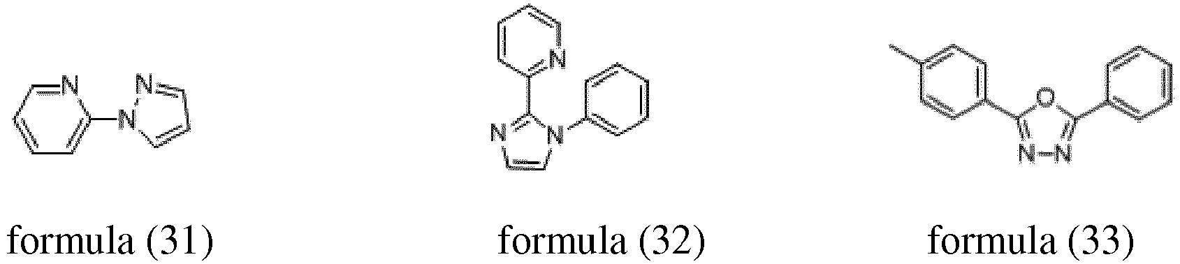

- The depositable ionic organic functional material according to Claim 1, characterized in that, the depositable ionic complex has a structure shown in the following formulas (11) to (16) and formulas (21) to (26):



- A use of the depositable ionic organic functional material according to Claim 1 or 2 in an organic electroluminescent device, wherein, the depositable ionic organic functional material is used as a dye in an organic light-emitting layer of the organic electroluminescent device.
- An organic electroluminescent device, comprising a substrate, and an anode layer, an organic light-emitting functional layer, a cathode layer formed in sequence upon the substrate, wherein the organic light-emitting functional layer comprises a hole transport layer, an organic light-emitting layer and an electron transport layer,characterized in that,a host material of the organic light-emitting layer is doped with the depositable ionic organic functional material according to Claim 1 or 2.
- The organic electroluminescent device according to Claim 4, characterized in that, doping concentration of the depositable ionic organic functional material is 2wt%-10wt%.
- The organic electroluminescent device according to Claim 4, characterized in that, the depositable ionic organic functional material is red, yellow, green or blue light emitting material.
- The organic electroluminescent device according to Claim 4, characterized in that, the organic light-emitting layer has a thickness of 10mm-50mm.
- The organic electroluminescent device according to Claim 7, characterized in that, the organic light-emitting layer has a thickness of 10mm-30mm.
Applications Claiming Priority (2)
| Application Number | Priority Date | Filing Date | Title |
|---|---|---|---|
| CN201510382459.7A CN106318377A (en) | 2015-07-02 | 2015-07-02 | Vapor-depositable ionic organic functional materials and their applications in organic electroluminescent devices |
| PCT/CN2016/085803 WO2017000778A1 (en) | 2015-07-02 | 2016-06-15 | Depositable ion organic function material and use thereof in organic electroluminescent device |
Publications (3)
| Publication Number | Publication Date |
|---|---|
| EP3318617A1 true EP3318617A1 (en) | 2018-05-09 |
| EP3318617A4 EP3318617A4 (en) | 2018-05-30 |
| EP3318617B1 EP3318617B1 (en) | 2019-08-14 |
Family
ID=57607836
Family Applications (1)
| Application Number | Title | Priority Date | Filing Date |
|---|---|---|---|
| EP16817142.9A Active EP3318617B1 (en) | 2015-07-02 | 2016-06-15 | Depositable ion organic function material and use thereof in organic electroluminescent device |
Country Status (6)
| Country | Link |
|---|---|
| US (1) | US10749128B2 (en) |
| EP (1) | EP3318617B1 (en) |
| KR (1) | KR102036775B1 (en) |
| CN (2) | CN106318377A (en) |
| TW (1) | TWI617534B (en) |
| WO (1) | WO2017000778A1 (en) |
Families Citing this family (1)
| Publication number | Priority date | Publication date | Assignee | Title |
|---|---|---|---|---|
| CN107936030A (en) * | 2017-11-21 | 2018-04-20 | 西北民族大学 | Water-soluble brominated copper porphyrin and its bromine substitutive derivative, its synthetic method and application |
Family Cites Families (7)
| Publication number | Priority date | Publication date | Assignee | Title |
|---|---|---|---|---|
| KR101202342B1 (en) * | 2005-02-04 | 2012-11-16 | 삼성디스플레이 주식회사 | Cyclometalated transition metal complex and organic electroluminescence device using the same |
| CN101186624B (en) * | 2007-08-16 | 2012-09-05 | 清华大学 | Iridium metal complex and application thereof |
| KR101594131B1 (en) * | 2009-01-22 | 2016-02-15 | 삼성전자주식회사 | Carbazole-based compound and organo-electroluminescent device using the same |
| CN101540375A (en) * | 2009-04-03 | 2009-09-23 | 清华大学 | Organic electroluminescence device |
| DE112011103600B4 (en) * | 2010-10-28 | 2018-05-03 | Furuya Metal Co., Ltd. | A method of producing a complex of tris-ortho metalated iridium |
| KR102146232B1 (en) * | 2012-12-21 | 2020-08-20 | 메르크 파텐트 게엠베하 | Metal complexes |
| KR102188214B1 (en) | 2012-12-21 | 2020-12-08 | 메르크 파텐트 게엠베하 | Metal complexes |
-
2015
- 2015-07-02 CN CN201510382459.7A patent/CN106318377A/en active Pending
- 2015-07-02 CN CN202110326205.9A patent/CN113072590A/en active Pending
-
2016
- 2016-06-15 EP EP16817142.9A patent/EP3318617B1/en active Active
- 2016-06-15 WO PCT/CN2016/085803 patent/WO2017000778A1/en not_active Ceased
- 2016-06-15 KR KR1020187003312A patent/KR102036775B1/en active Active
- 2016-06-15 US US15/745,060 patent/US10749128B2/en active Active
- 2016-06-15 TW TW105118811A patent/TWI617534B/en active
Also Published As
| Publication number | Publication date |
|---|---|
| KR102036775B1 (en) | 2019-10-25 |
| EP3318617B1 (en) | 2019-08-14 |
| TW201730141A (en) | 2017-09-01 |
| US10749128B2 (en) | 2020-08-18 |
| TWI617534B (en) | 2018-03-11 |
| KR20180026501A (en) | 2018-03-12 |
| WO2017000778A1 (en) | 2017-01-05 |
| CN106318377A (en) | 2017-01-11 |
| CN113072590A (en) | 2021-07-06 |
| US20180277785A1 (en) | 2018-09-27 |
| EP3318617A4 (en) | 2018-05-30 |
Similar Documents
| Publication | Publication Date | Title |
|---|---|---|
| JP7508127B2 (en) | Organic layer | |
| EP3226318B1 (en) | Thermally-activated sensitized phosphorescent organic electroluminescent device | |
| EP3070757B1 (en) | Organic electroluminescent device and method for manufacture thereof | |
| EP2192633B1 (en) | Light-emitting element, light-emitting device, lighting device, and electronic device | |
| CN1922284B (en) | Improved electroluminescent stability | |
| CN114920757A (en) | Organic electroluminescent materials and devices | |
| Chen et al. | A meta-molecular tailoring strategy towards an efficient violet-blue organic electroluminescent material | |
| CN105576138B (en) | Platinum (II) isoquinoline-pyridine-benzene-based complex, preparation method thereof and organic light emitting diode prepared therefrom | |
| CN104617229A (en) | Organic electroluminescent device | |
| CN102349129B (en) | OLED devices with fluoranthene macrocycles | |
| CN103250264A (en) | Light emitting element material and light emitting element | |
| CN104529940B (en) | A kind of phenthazine dioxide derivative, preparation method and organic luminescent device | |
| Fang et al. | Improved efficiency by a fluorescent dye in red organic light-emitting devices based on a europium complex | |
| Jeon et al. | New sulfone-based electron-transport materials with high triplet energy for highly efficient blue phosphorescent organic light-emitting diodes | |
| CN102214798B (en) | White light organic electroluminescent device and manufacturing method thereof | |
| CN102369102A (en) | OLED devices containing silylfluoranthene derivatives | |
| Wang et al. | Controllable molecular configuration for significant improvement of blue OLEDs based on novel twisted anthracene derivatives | |
| WO2018077689A1 (en) | Compound for electronic device and electronic device and display device | |
| Zhuang et al. | Novel ternary bipolar host material with carbazole, triazole and phosphine oxide moieties for high efficiency sky-blue OLEDs | |
| CN104478870B (en) | A kind of phenothiazine dioxide derivative preparation and application thereof | |
| CN110783462A (en) | Electronic device, display device, method for producing the same, and compound | |
| CN109503576B (en) | Organic compound, display panel and display device | |
| CN106316960A (en) | Benzimidazole n-type dopant and its application in organic electroluminescent devices | |
| CN105374949A (en) | Organic light-emitting device and preparation method thereof | |
| CN106898709A (en) | A kind of red phosphorescent organic electroluminescence device |
Legal Events
| Date | Code | Title | Description |
|---|---|---|---|
| STAA | Information on the status of an ep patent application or granted ep patent |
Free format text: STATUS: THE INTERNATIONAL PUBLICATION HAS BEEN MADE |
|
| PUAI | Public reference made under article 153(3) epc to a published international application that has entered the european phase |
Free format text: ORIGINAL CODE: 0009012 |
|
| STAA | Information on the status of an ep patent application or granted ep patent |
Free format text: STATUS: REQUEST FOR EXAMINATION WAS MADE |
|
| 17P | Request for examination filed |
Effective date: 20180202 |
|
| AK | Designated contracting states |
Kind code of ref document: A1 Designated state(s): AL AT BE BG CH CY CZ DE DK EE ES FI FR GB GR HR HU IE IS IT LI LT LU LV MC MK MT NL NO PL PT RO RS SE SI SK SM TR |
|
| AX | Request for extension of the european patent |
Extension state: BA ME |
|
| A4 | Supplementary search report drawn up and despatched |
Effective date: 20180502 |
|
| RIC1 | Information provided on ipc code assigned before grant |
Ipc: C07F 15/00 20060101ALI20180424BHEP Ipc: H01L 51/54 20060101ALI20180424BHEP Ipc: C09K 11/06 20060101AFI20180424BHEP |
|
| DAV | Request for validation of the european patent (deleted) | ||
| DAX | Request for extension of the european patent (deleted) | ||
| GRAP | Despatch of communication of intention to grant a patent |
Free format text: ORIGINAL CODE: EPIDOSNIGR1 |
|
| STAA | Information on the status of an ep patent application or granted ep patent |
Free format text: STATUS: GRANT OF PATENT IS INTENDED |
|
| INTG | Intention to grant announced |
Effective date: 20190308 |
|
| GRAS | Grant fee paid |
Free format text: ORIGINAL CODE: EPIDOSNIGR3 |
|
| GRAA | (expected) grant |
Free format text: ORIGINAL CODE: 0009210 |
|
| STAA | Information on the status of an ep patent application or granted ep patent |
Free format text: STATUS: THE PATENT HAS BEEN GRANTED |
|
| AK | Designated contracting states |
Kind code of ref document: B1 Designated state(s): AL AT BE BG CH CY CZ DE DK EE ES FI FR GB GR HR HU IE IS IT LI LT LU LV MC MK MT NL NO PL PT RO RS SE SI SK SM TR |
|
| REG | Reference to a national code |
Ref country code: GB Ref legal event code: FG4D |
|
| REG | Reference to a national code |
Ref country code: CH Ref legal event code: EP Ref country code: AT Ref legal event code: REF Ref document number: 1167008 Country of ref document: AT Kind code of ref document: T Effective date: 20190815 |
|
| REG | Reference to a national code |
Ref country code: IE Ref legal event code: FG4D |
|
| REG | Reference to a national code |
Ref country code: DE Ref legal event code: R096 Ref document number: 602016018787 Country of ref document: DE |
|
| REG | Reference to a national code |
Ref country code: NL Ref legal event code: MP Effective date: 20190814 |
|
| REG | Reference to a national code |
Ref country code: LT Ref legal event code: MG4D |
|
| PG25 | Lapsed in a contracting state [announced via postgrant information from national office to epo] |
Ref country code: FI Free format text: LAPSE BECAUSE OF FAILURE TO SUBMIT A TRANSLATION OF THE DESCRIPTION OR TO PAY THE FEE WITHIN THE PRESCRIBED TIME-LIMIT Effective date: 20190814 Ref country code: PT Free format text: LAPSE BECAUSE OF FAILURE TO SUBMIT A TRANSLATION OF THE DESCRIPTION OR TO PAY THE FEE WITHIN THE PRESCRIBED TIME-LIMIT Effective date: 20191216 Ref country code: HR Free format text: LAPSE BECAUSE OF FAILURE TO SUBMIT A TRANSLATION OF THE DESCRIPTION OR TO PAY THE FEE WITHIN THE PRESCRIBED TIME-LIMIT Effective date: 20190814 Ref country code: NL Free format text: LAPSE BECAUSE OF FAILURE TO SUBMIT A TRANSLATION OF THE DESCRIPTION OR TO PAY THE FEE WITHIN THE PRESCRIBED TIME-LIMIT Effective date: 20190814 Ref country code: SE Free format text: LAPSE BECAUSE OF FAILURE TO SUBMIT A TRANSLATION OF THE DESCRIPTION OR TO PAY THE FEE WITHIN THE PRESCRIBED TIME-LIMIT Effective date: 20190814 Ref country code: LT Free format text: LAPSE BECAUSE OF FAILURE TO SUBMIT A TRANSLATION OF THE DESCRIPTION OR TO PAY THE FEE WITHIN THE PRESCRIBED TIME-LIMIT Effective date: 20190814 Ref country code: BG Free format text: LAPSE BECAUSE OF FAILURE TO SUBMIT A TRANSLATION OF THE DESCRIPTION OR TO PAY THE FEE WITHIN THE PRESCRIBED TIME-LIMIT Effective date: 20191114 Ref country code: NO Free format text: LAPSE BECAUSE OF FAILURE TO SUBMIT A TRANSLATION OF THE DESCRIPTION OR TO PAY THE FEE WITHIN THE PRESCRIBED TIME-LIMIT Effective date: 20191114 |
|
| REG | Reference to a national code |
Ref country code: AT Ref legal event code: MK05 Ref document number: 1167008 Country of ref document: AT Kind code of ref document: T Effective date: 20190814 |
|
| PG25 | Lapsed in a contracting state [announced via postgrant information from national office to epo] |
Ref country code: ES Free format text: LAPSE BECAUSE OF FAILURE TO SUBMIT A TRANSLATION OF THE DESCRIPTION OR TO PAY THE FEE WITHIN THE PRESCRIBED TIME-LIMIT Effective date: 20190814 Ref country code: LV Free format text: LAPSE BECAUSE OF FAILURE TO SUBMIT A TRANSLATION OF THE DESCRIPTION OR TO PAY THE FEE WITHIN THE PRESCRIBED TIME-LIMIT Effective date: 20190814 Ref country code: IS Free format text: LAPSE BECAUSE OF FAILURE TO SUBMIT A TRANSLATION OF THE DESCRIPTION OR TO PAY THE FEE WITHIN THE PRESCRIBED TIME-LIMIT Effective date: 20191214 Ref country code: AL Free format text: LAPSE BECAUSE OF FAILURE TO SUBMIT A TRANSLATION OF THE DESCRIPTION OR TO PAY THE FEE WITHIN THE PRESCRIBED TIME-LIMIT Effective date: 20190814 Ref country code: GR Free format text: LAPSE BECAUSE OF FAILURE TO SUBMIT A TRANSLATION OF THE DESCRIPTION OR TO PAY THE FEE WITHIN THE PRESCRIBED TIME-LIMIT Effective date: 20191115 Ref country code: RS Free format text: LAPSE BECAUSE OF FAILURE TO SUBMIT A TRANSLATION OF THE DESCRIPTION OR TO PAY THE FEE WITHIN THE PRESCRIBED TIME-LIMIT Effective date: 20190814 |
|
| PG25 | Lapsed in a contracting state [announced via postgrant information from national office to epo] |
Ref country code: TR Free format text: LAPSE BECAUSE OF FAILURE TO SUBMIT A TRANSLATION OF THE DESCRIPTION OR TO PAY THE FEE WITHIN THE PRESCRIBED TIME-LIMIT Effective date: 20190814 |
|
| PG25 | Lapsed in a contracting state [announced via postgrant information from national office to epo] |
Ref country code: IT Free format text: LAPSE BECAUSE OF FAILURE TO SUBMIT A TRANSLATION OF THE DESCRIPTION OR TO PAY THE FEE WITHIN THE PRESCRIBED TIME-LIMIT Effective date: 20190814 Ref country code: EE Free format text: LAPSE BECAUSE OF FAILURE TO SUBMIT A TRANSLATION OF THE DESCRIPTION OR TO PAY THE FEE WITHIN THE PRESCRIBED TIME-LIMIT Effective date: 20190814 Ref country code: RO Free format text: LAPSE BECAUSE OF FAILURE TO SUBMIT A TRANSLATION OF THE DESCRIPTION OR TO PAY THE FEE WITHIN THE PRESCRIBED TIME-LIMIT Effective date: 20190814 Ref country code: AT Free format text: LAPSE BECAUSE OF FAILURE TO SUBMIT A TRANSLATION OF THE DESCRIPTION OR TO PAY THE FEE WITHIN THE PRESCRIBED TIME-LIMIT Effective date: 20190814 Ref country code: DK Free format text: LAPSE BECAUSE OF FAILURE TO SUBMIT A TRANSLATION OF THE DESCRIPTION OR TO PAY THE FEE WITHIN THE PRESCRIBED TIME-LIMIT Effective date: 20190814 Ref country code: PL Free format text: LAPSE BECAUSE OF FAILURE TO SUBMIT A TRANSLATION OF THE DESCRIPTION OR TO PAY THE FEE WITHIN THE PRESCRIBED TIME-LIMIT Effective date: 20190814 |
|
| PG25 | Lapsed in a contracting state [announced via postgrant information from national office to epo] |
Ref country code: CZ Free format text: LAPSE BECAUSE OF FAILURE TO SUBMIT A TRANSLATION OF THE DESCRIPTION OR TO PAY THE FEE WITHIN THE PRESCRIBED TIME-LIMIT Effective date: 20190814 Ref country code: SK Free format text: LAPSE BECAUSE OF FAILURE TO SUBMIT A TRANSLATION OF THE DESCRIPTION OR TO PAY THE FEE WITHIN THE PRESCRIBED TIME-LIMIT Effective date: 20190814 Ref country code: IS Free format text: LAPSE BECAUSE OF FAILURE TO SUBMIT A TRANSLATION OF THE DESCRIPTION OR TO PAY THE FEE WITHIN THE PRESCRIBED TIME-LIMIT Effective date: 20200224 Ref country code: SM Free format text: LAPSE BECAUSE OF FAILURE TO SUBMIT A TRANSLATION OF THE DESCRIPTION OR TO PAY THE FEE WITHIN THE PRESCRIBED TIME-LIMIT Effective date: 20190814 |
|
| REG | Reference to a national code |
Ref country code: DE Ref legal event code: R097 Ref document number: 602016018787 Country of ref document: DE |
|
| PLBE | No opposition filed within time limit |
Free format text: ORIGINAL CODE: 0009261 |
|
| STAA | Information on the status of an ep patent application or granted ep patent |
Free format text: STATUS: NO OPPOSITION FILED WITHIN TIME LIMIT |
|
| PG2D | Information on lapse in contracting state deleted |
Ref country code: IS |
|
| 26N | No opposition filed |
Effective date: 20200603 |
|
| PG25 | Lapsed in a contracting state [announced via postgrant information from national office to epo] |
Ref country code: SI Free format text: LAPSE BECAUSE OF FAILURE TO SUBMIT A TRANSLATION OF THE DESCRIPTION OR TO PAY THE FEE WITHIN THE PRESCRIBED TIME-LIMIT Effective date: 20190814 |
|
| PG25 | Lapsed in a contracting state [announced via postgrant information from national office to epo] |
Ref country code: MC Free format text: LAPSE BECAUSE OF FAILURE TO SUBMIT A TRANSLATION OF THE DESCRIPTION OR TO PAY THE FEE WITHIN THE PRESCRIBED TIME-LIMIT Effective date: 20190814 |
|
| REG | Reference to a national code |
Ref country code: CH Ref legal event code: PL |
|
| PG25 | Lapsed in a contracting state [announced via postgrant information from national office to epo] |
Ref country code: LU Free format text: LAPSE BECAUSE OF NON-PAYMENT OF DUE FEES Effective date: 20200615 |
|
| REG | Reference to a national code |
Ref country code: BE Ref legal event code: MM Effective date: 20200630 |
|
| PG25 | Lapsed in a contracting state [announced via postgrant information from national office to epo] |
Ref country code: IE Free format text: LAPSE BECAUSE OF NON-PAYMENT OF DUE FEES Effective date: 20200615 Ref country code: LI Free format text: LAPSE BECAUSE OF NON-PAYMENT OF DUE FEES Effective date: 20200630 Ref country code: CH Free format text: LAPSE BECAUSE OF NON-PAYMENT OF DUE FEES Effective date: 20200630 |
|
| PG25 | Lapsed in a contracting state [announced via postgrant information from national office to epo] |
Ref country code: BE Free format text: LAPSE BECAUSE OF NON-PAYMENT OF DUE FEES Effective date: 20200630 |
|
| PG25 | Lapsed in a contracting state [announced via postgrant information from national office to epo] |
Ref country code: MT Free format text: LAPSE BECAUSE OF FAILURE TO SUBMIT A TRANSLATION OF THE DESCRIPTION OR TO PAY THE FEE WITHIN THE PRESCRIBED TIME-LIMIT Effective date: 20190814 Ref country code: CY Free format text: LAPSE BECAUSE OF FAILURE TO SUBMIT A TRANSLATION OF THE DESCRIPTION OR TO PAY THE FEE WITHIN THE PRESCRIBED TIME-LIMIT Effective date: 20190814 |
|
| PG25 | Lapsed in a contracting state [announced via postgrant information from national office to epo] |
Ref country code: MK Free format text: LAPSE BECAUSE OF FAILURE TO SUBMIT A TRANSLATION OF THE DESCRIPTION OR TO PAY THE FEE WITHIN THE PRESCRIBED TIME-LIMIT Effective date: 20190814 |
|
| P01 | Opt-out of the competence of the unified patent court (upc) registered |
Effective date: 20230526 |
|
| PGFP | Annual fee paid to national office [announced via postgrant information from national office to epo] |
Ref country code: DE Payment date: 20250617 Year of fee payment: 10 |
|
| PGFP | Annual fee paid to national office [announced via postgrant information from national office to epo] |
Ref country code: GB Payment date: 20250625 Year of fee payment: 10 |
|
| PGFP | Annual fee paid to national office [announced via postgrant information from national office to epo] |
Ref country code: FR Payment date: 20250630 Year of fee payment: 10 |