EP3318345A1 - Method and system for producing ring-shaped member for vehicle, and synchronizer ring - Google Patents
Method and system for producing ring-shaped member for vehicle, and synchronizer ring Download PDFInfo
- Publication number
- EP3318345A1 EP3318345A1 EP16875774.8A EP16875774A EP3318345A1 EP 3318345 A1 EP3318345 A1 EP 3318345A1 EP 16875774 A EP16875774 A EP 16875774A EP 3318345 A1 EP3318345 A1 EP 3318345A1
- Authority
- EP
- European Patent Office
- Prior art keywords
- ring
- punching
- shaped
- shaped member
- circumferential direction
- Prior art date
- Legal status (The legal status is an assumption and is not a legal conclusion. Google has not performed a legal analysis and makes no representation as to the accuracy of the status listed.)
- Granted
Links
Images





Classifications
-
- B—PERFORMING OPERATIONS; TRANSPORTING
- B21—MECHANICAL METAL-WORKING WITHOUT ESSENTIALLY REMOVING MATERIAL; PUNCHING METAL
- B21D—WORKING OR PROCESSING OF SHEET METAL OR METAL TUBES, RODS OR PROFILES WITHOUT ESSENTIALLY REMOVING MATERIAL; PUNCHING METAL
- B21D28/00—Shaping by press-cutting; Perforating
- B21D28/24—Perforating, i.e. punching holes
- B21D28/36—Perforating, i.e. punching holes using rotatable work or tool holders
-
- B—PERFORMING OPERATIONS; TRANSPORTING
- B21—MECHANICAL METAL-WORKING WITHOUT ESSENTIALLY REMOVING MATERIAL; PUNCHING METAL
- B21D—WORKING OR PROCESSING OF SHEET METAL OR METAL TUBES, RODS OR PROFILES WITHOUT ESSENTIALLY REMOVING MATERIAL; PUNCHING METAL
- B21D28/00—Shaping by press-cutting; Perforating
- B21D28/24—Perforating, i.e. punching holes
- B21D28/30—Perforating, i.e. punching holes in annular parts, e.g. rims
-
- B—PERFORMING OPERATIONS; TRANSPORTING
- B21—MECHANICAL METAL-WORKING WITHOUT ESSENTIALLY REMOVING MATERIAL; PUNCHING METAL
- B21D—WORKING OR PROCESSING OF SHEET METAL OR METAL TUBES, RODS OR PROFILES WITHOUT ESSENTIALLY REMOVING MATERIAL; PUNCHING METAL
- B21D28/00—Shaping by press-cutting; Perforating
-
- B—PERFORMING OPERATIONS; TRANSPORTING
- B21—MECHANICAL METAL-WORKING WITHOUT ESSENTIALLY REMOVING MATERIAL; PUNCHING METAL
- B21D—WORKING OR PROCESSING OF SHEET METAL OR METAL TUBES, RODS OR PROFILES WITHOUT ESSENTIALLY REMOVING MATERIAL; PUNCHING METAL
- B21D28/00—Shaping by press-cutting; Perforating
- B21D28/02—Punching blanks or articles with or without obtaining scrap; Notching
-
- B—PERFORMING OPERATIONS; TRANSPORTING
- B21—MECHANICAL METAL-WORKING WITHOUT ESSENTIALLY REMOVING MATERIAL; PUNCHING METAL
- B21D—WORKING OR PROCESSING OF SHEET METAL OR METAL TUBES, RODS OR PROFILES WITHOUT ESSENTIALLY REMOVING MATERIAL; PUNCHING METAL
- B21D28/00—Shaping by press-cutting; Perforating
- B21D28/24—Perforating, i.e. punching holes
- B21D28/28—Perforating, i.e. punching holes in tubes or other hollow bodies
-
- B—PERFORMING OPERATIONS; TRANSPORTING
- B21—MECHANICAL METAL-WORKING WITHOUT ESSENTIALLY REMOVING MATERIAL; PUNCHING METAL
- B21D—WORKING OR PROCESSING OF SHEET METAL OR METAL TUBES, RODS OR PROFILES WITHOUT ESSENTIALLY REMOVING MATERIAL; PUNCHING METAL
- B21D51/00—Making hollow objects
- B21D51/16—Making hollow objects characterised by the use of the objects
-
- B—PERFORMING OPERATIONS; TRANSPORTING
- B21—MECHANICAL METAL-WORKING WITHOUT ESSENTIALLY REMOVING MATERIAL; PUNCHING METAL
- B21D—WORKING OR PROCESSING OF SHEET METAL OR METAL TUBES, RODS OR PROFILES WITHOUT ESSENTIALLY REMOVING MATERIAL; PUNCHING METAL
- B21D53/00—Making other particular articles
- B21D53/16—Making other particular articles rings, e.g. barrel hoops
-
- B—PERFORMING OPERATIONS; TRANSPORTING
- B21—MECHANICAL METAL-WORKING WITHOUT ESSENTIALLY REMOVING MATERIAL; PUNCHING METAL
- B21D—WORKING OR PROCESSING OF SHEET METAL OR METAL TUBES, RODS OR PROFILES WITHOUT ESSENTIALLY REMOVING MATERIAL; PUNCHING METAL
- B21D53/00—Making other particular articles
- B21D53/84—Making other particular articles other parts for engines, e.g. connecting-rods
-
- B—PERFORMING OPERATIONS; TRANSPORTING
- B21—MECHANICAL METAL-WORKING WITHOUT ESSENTIALLY REMOVING MATERIAL; PUNCHING METAL
- B21K—MAKING FORGED OR PRESSED METAL PRODUCTS, e.g. HORSE-SHOES, RIVETS, BOLTS OR WHEELS
- B21K1/00—Making machine elements
- B21K1/28—Making machine elements wheels; discs
- B21K1/30—Making machine elements wheels; discs with gear-teeth
-
- F—MECHANICAL ENGINEERING; LIGHTING; HEATING; WEAPONS; BLASTING
- F16—ENGINEERING ELEMENTS AND UNITS; GENERAL MEASURES FOR PRODUCING AND MAINTAINING EFFECTIVE FUNCTIONING OF MACHINES OR INSTALLATIONS; THERMAL INSULATION IN GENERAL
- F16D—COUPLINGS FOR TRANSMITTING ROTATION; CLUTCHES; BRAKES
- F16D23/00—Details of mechanically-actuated clutches not specific for one distinct type
- F16D23/02—Arrangements for synchronisation, also for power-operated clutches
- F16D23/025—Synchro rings
-
- F—MECHANICAL ENGINEERING; LIGHTING; HEATING; WEAPONS; BLASTING
- F16—ENGINEERING ELEMENTS AND UNITS; GENERAL MEASURES FOR PRODUCING AND MAINTAINING EFFECTIVE FUNCTIONING OF MACHINES OR INSTALLATIONS; THERMAL INSULATION IN GENERAL
- F16D—COUPLINGS FOR TRANSMITTING ROTATION; CLUTCHES; BRAKES
- F16D23/00—Details of mechanically-actuated clutches not specific for one distinct type
- F16D23/02—Arrangements for synchronisation, also for power-operated clutches
- F16D23/04—Arrangements for synchronisation, also for power-operated clutches with an additional friction clutch
- F16D23/06—Arrangements for synchronisation, also for power-operated clutches with an additional friction clutch and a blocking mechanism preventing the engagement of the main clutch prior to synchronisation
-
- F—MECHANICAL ENGINEERING; LIGHTING; HEATING; WEAPONS; BLASTING
- F16—ENGINEERING ELEMENTS AND UNITS; GENERAL MEASURES FOR PRODUCING AND MAINTAINING EFFECTIVE FUNCTIONING OF MACHINES OR INSTALLATIONS; THERMAL INSULATION IN GENERAL
- F16D—COUPLINGS FOR TRANSMITTING ROTATION; CLUTCHES; BRAKES
- F16D2250/00—Manufacturing; Assembly
- F16D2250/0023—Shaping by pressure
Definitions
- the present invention relates to a method and a system for manufacturing a ring-shaped member for a vehicle having a claw piece such as a synchronizer ring incorporated in a manual transmission.
- a synchronization mechanism is incorporated in a manual transmission so that a drive shaft rotates in synchronism with a transmission gear at the time of a gear shift operation.
- a synchronizer ring is incorporated in such a synchronization mechanism.
- a double-cone type thereof described in Patent Document 1 is illustrated in Fig. 8 .
- an insert spring 4 is mounted on an outer circumference of a synchronizing hub 3 which rotates together with a drive shaft 2, and a coupling sleeve 5 displaced in an axial direction on the basis of an operation of a shift lever is engaged with the insert spring 4.
- An outer balk ring 8, a synchronizer ring 1, and an inner balk ring 9 are provided between the coupling sleeve 5 and a clutch gear 7 which rotates in synchronism with a transmission gear 6.
- a spline groove 10 formed on an inner circumferential surface of the coupling sleeve 5 engages with a spline groove 11 formed on an outer circumferential edge of the clutch gear 7 and a spline groove 12 formed on an outer circumferential edge of the insert spring 4 so as to stretch over them, and thus the drive shaft 2 rotates in synchronism with the transmission gear 6.
- the synchronizer ring 1 incorporated in the synchronization mechanism configured and operating as described above is configured in a shape, for example, as illustrated in Figs. 9 and 10 . That is, the synchronizer ring 1 is constituted by a tapered cylindrical portion 13 of which a diameter changes in the axial direction, and claw pieces 15 and 15 formed at regular intervals at a plurality of positions on a large diameter side end surface 14 of the tapered cylindrical portion 13. A thickness dimension t of each of the claw pieces 15 and 15 is smaller than a thickness dimension T of the tapered cylindrical portion 13 (T> t).
- a direction of each of the claw pieces 15 and 15 is different depending on a structure of synchronization mechanisms into which the synchronizer ring 1 is to be incorporated, and may be inclined in the same direction as the tapered cylindrical portion 13, or the claw pieces 15 and 15 may be parallel to each other.
- a method of manufacturing the synchronizer ring 1 having such a shape a method of manufacturing the synchronizer ring 1 at low cost by subjecting a flat metal plate to press processing is described in Patent Document 1.
- Figs. 11 to 15 illustrate a manufacturing method of a synchronizer ring described in Patent Document 1 and conventionally known.
- a first ring-shaped workpiece 16 as illustrated in Figs. 12 and 13 is formed by so-called blanking which punches out a flat metal plate such as carburized steel such as SCr420.
- the first ring-shaped workpiece 16 includes an annular main body portion 17 and tongue-shaped portions 18 and 18 protruding from a plurality of positions on an outer circumferential edge of the main body portion 17.
- a second ring-shaped workpiece 19 as illustrated in Figs. 14 and 15 is formed by press-molding the first ring-shaped workpiece 16. That is, in the molding step, the main body portion 17 ( Figs. 12 and 13 ) is formed into a tapered cylindrical portion 20 inclined in a direction in which a diameter thereof decreases with distance away from the tongue-shaped portions 18 and 18 so that the second ring-shaped workpiece 19 is formed. Next, an end surface of the tapered cylindrical portion 20 and each of the tongue-shaped portions 18 and 18 which constitute the second ring-shaped workpiece 19 are subjected to machining such as turning so that the tapered cylindrical portion 20 and each of the tongue-shaped portions 18 and 18 have predetermined shapes and dimensions.
- heat treatment is performed to obtain a desired hardness.
- a carburizing heat treatment is performed, and thereafter, deformation based on heat treatment is corrected.
- a third ring-shaped workpiece on which such a heat treatment is performed as above is subjected to surface grinding for finishing flat surfaces of the respective tongue-shaped portions 18 and 18 to form the respective claw pieces 15 and 15 as well as inner and outer diameter grinding for smoothing both the inner and outer circumferential surfaces of the tapered cylindrical portion 20 to form the tapered cylindrical portion 13 so that the synchronizer ring 1 is formed.
- the synchronizer ring 1 manufactured in this manner is shipped after performing a predetermined inspection.
- one synchronizer ring 1 is formed from the first ring-shaped workpiece 16 formed by applying a punching process to a flat metal plate. Therefore, there is room for improvement from a manufacturing efficiency perspective.
- Patent Document 1 Japanese Patent Application, Publication No H03-297527
- An aspect of the present invention is directed to realizing a method and a system of manufacturing a ring-shaped member capable of improving manufacturing efficiency.
- a method of manufacturing a ring-shaped member for a vehicle includes a punching step of punching out an axial intermediate portion of a ring-shaped workpiece entirely in a circumferential direction so that a first ring-shaped member and a second ring-shaped member each having at least one claw piece are formed, in which the punching step includes a step of performing a first punching process on a first region of the intermediate portion in the circumferential direction, and a step of performing a second punching process on a second region of the intermediate portion which is at least partially different from the first region in the circumferential direction.
- a method of manufacturing a ring-shaped member for a vehicle includes a punching step of punching out an axial intermediate portion of a ring-shaped workpiece so that a first ring-shaped member and a second ring-shaped member each having at least one claw piece are formed, in which the punching step has a step of performing a first punching process on a first region of the intermediate portion in a circumferential direction, and a step of performing a second punching process on a second region of the intermediate portion which is at least partially different from the first region in the circumferential direction, and the method further includes a step of forming a concave surface extending in the circumferential direction on an inner circumference of the intermediate portion before the punching step.
- Another aspect of the present invention is a synchronizer ring manufactured using the above-described manufacturing method.
- a system of manufacturing a ring-shaped member for a vehicle includes a first device which punches out an axial intermediate portion of a ring-shaped workpiece entirely in the circumferential direction so that a first ring-shaped member and a second ring-shaped member each having at least one claw piece are formed, in which the first device performs a first punching process on a first region of the intermediate portion in the circumferential direction, and a second punching process on a second region of the intermediate portion which is at least partially different from the first region in the circumferential direction.
- a system of manufacturing a ring-shaped member for a vehicle includes a first device which punches out an axial intermediate portion of a ring-shaped workpiece so that a first ring-shaped member and a second ring-shaped member each having at least one claw piece are formed, the first device performing a first punching process on a first region of the intermediate portion in a circumferential direction and a second punching process on a second region of the intermediate portion which is at least partially different from the first region in the circumferential direction, and a second device which forms a concave surface extending in the circumferential direction on an inner circumference of the intermediate portion before the punching process of the first device.
- a method of manufacturing a ring-shaped member according to another aspect of the present invention has a target of a ring-shaped member including a cylindrical portion, and a claw piece formed on an axial end surface of the cylindrical portion in a state of protruding in the axial direction from the axial end surface.
- Such a manufacturing method includes a step of manufacturing a pair of ring-shaped members in which at least one claw piece protruding in the axial direction from an end surface is provided on the end surface of each punched side by the punching process for punching out the entire circumference of the axial intermediate portion with respect to a first ring-shaped workpiece. In such a punching process, the entire circumference of the axial intermediate portion of the first ring-shaped workpiece can be punched out at once or punched out by punching a plurality of times.
- the ring-shaped workpiece is formed by forging a material cut out from a solid wire rod.
- various methods such as cold forging, hot forging, or warm forging can be employed, for example.
- an inner circumferential surface and an outer circumferential surface of the first ring-shaped workpiece are inclined in a direction in which an outer diameter and an inner diameter become larger toward the axial center portion.
- a pair of ring-shaped members can be formed from a first ring-shaped workpiece. Therefore, manufacturing efficiency can be improved compared to a manufacturing method in which one ring-shaped member is formed from one ring-shaped workpiece.
- a first example of an embodiment of the present invention will be described with reference to Figs. 1 to 3 .
- a method of manufacturing a ring-shaped member of the present invention is applied to a synchronizer ring.
- the synchronizer ring which is an object of the manufacturing method of the present example can be applied not only to a synchronization mechanism illustrated in Fig. 8 but also to various synchronization mechanisms appropriately. Description of a structure of the synchronization mechanism will be omitted.
- the method of manufacturing the ring-shaped member of the present example will be described.
- a synchronizer ring 1a (1b) includes a tapered cylindrical portion (a tubular portion, a truncated-cone like tube) 13a (13b), and a plurality of claw pieces 15a (15b) (three in the present example).
- the tapered cylindrical portion 13a (13b) includes a tubular portion (a tapered tubular portion (taper tube)) in which a diameter of an inner circumferential surface and/or an outer circumferential surface decreases toward one end edge in an axial direction, a conical tubular portion (cone tube), and a partial conical surface (partial cone surface).
- both the inner circumferential surface and the outer circumferential surface of the tapered cylindrical portion 13a (13b) are inclined in a direction in which an inner diameter and an outer diameter become larger toward one side in the axial direction ⁇ upper side (lower side) of Fig. 1(G) (b) ⁇ .
- Each of the claw pieces (tags) 15a (15b) is formed in a state of extending toward one side in the axial direction from a large diameter side end surface 14a (14b) (end surface in the axial direction, one end surface in the axial direction) of the tapered cylindrical portion 13a (13b).
- three claw pieces 15a (15b) are disposed at regular intervals in the circumferential direction on the axial end surface 14a (14b).
- a plurality of claw pieces can be disposed at non-regular intervals in the circumferential direction.
- the number of claw pieces can be other than three.
- each of the claw pieces 15a (15b) includes a first side and a second side extending at least in the axial direction from the axial end surface 14a, and a third side extending in the circumferential direction.
- the first side and the second side are disposed to be spaced apart in the circumferential direction.
- the third side connects an end of the first side and an end of the second side.
- an angle (inclination angle) of each of the claw pieces 15a and 15a with respect to a ring axis can be appropriately determined.
- a coil-shaped (or long rod-shaped) solid wire rod made of chromium steel such as SCr420, chromium molybdenum steel such as SCM420, high carbon chromium bearing steel such as SUJ2, or the like is cut into a desired length by an appropriate method such as pressing, saw cutting, laser cutting, or the like to obtain a columnar raw material (billet) 20 illustrated in Fig. 1(A) .
- a columnar raw material (billet) 20 illustrated in Fig. 1(A) .
- another material can be used.
- the raw material 20 is subjected to an upsetting process to form a columnar first workpiece 21 as illustrated in Fig. 1(B) having a smaller axial dimension and a larger radial dimension (diameter) than those of the raw material 20.
- the upsetting process is performed by forging.
- the first workpiece 21 is subjected to a backward extrusion process to form a second workpiece 22 having a bottomed cylindrical shape as illustrated in Fig. 1(C) .
- the backward extrusion process also is performed by forging.
- a bottom portion 23 of the second workpiece 22 is punched out to form a ring-shaped workpiece 24 as illustrated in Fig. 1(D) .
- the ring-shaped workpiece 24 has a cylindrical shape in which an inner diameter and an outer diameter do not change in the axial direction.
- an outer circumferential surface of the first ring-shaped workpiece 25 has a largest outer diameter at an axial center portion 29 and has a smaller outer diameter toward both end sides in the axial direction.
- an inner circumferential surface of the first ring-shaped workpiece 25 has a concave arcuate portion 26 formed at an axial intermediate portion including the axial center portion 29, and inclined curved surface portions 27 and 27 provided adjacent to both sides in the axial direction of the concave arcuate portion 26.
- the concave arcuate portion 26 is formed to have a largest inner diameter at a portion corresponding to the axial center portion 29 and to have a smaller inner diameter toward both end sides in the axial direction.
- the concave arcuate portion (concave surface) 26 continuously extending in the circumferential direction is formed on an inner circumferential surface of the axial center portion (axial intermediate portion) 29 of the first ring-shaped workpiece 25. That is, a step of forming the concave surface extending in the circumferential direction on the inner circumference of the intermediate portion 29 is performed before a punching step to be described below.
- the concave arcuate portion (concave surface) 26 can be formed in the circumferential direction over the entire inner circumference of the intermediate portion 29.
- the concave arcuate portion (concave surface) 26 can be formed in a portion of the inner circumference of the intermediate portion 29 in the circumferential direction.
- each of the inclined curved surface portions 27 and 27 is formed in an inclined curved surface shape in which an inner diameter on the axial center side (a side close to the concave arcuate portion 26) is the largest and the inner diameter decreases toward both end sides in the axial direction. Also, a thickness dimension of the first ring-shaped workpiece 25 in the radial direction is formed such that a thickness dimension of a portion corresponding to the concave arcuate portion 26 is smaller than a thickness dimension of portions corresponding to each of the inclined curved surface portions 27 and 27.
- the first ring-shaped workpiece 25 having such a configuration as described above has a symmetrical shape (symmetrical with respect to a virtual plane ⁇ which is perpendicular to the central axis of the first ring-shaped workpiece 25 and passing through the axial center portion 29) with respect to the axial direction ⁇ vertical direction in Fig. 1(E)(b) ⁇ .
- a central band-shaped portion 30 (the axial center portion 29, intermediate portion) corresponding to a portion in which the concave arcuate portion 26 is formed in the first ring-shaped workpiece 25 is subjected to a punching process to form a pair of ring-shaped members (a first ring-shaped member 28A and a second ring-shaped member 28B) as illustrated in Figs. 1(F) and 2(B) .
- the punching step includes a step of performing a first punching process on a first region of the central band-shaped portion 30 (the axial center portion 29, the intermediate portion) in the circumferential direction, and a step of performing a second punching process on a second region of the central band-shaped portion 30 which is at least partially different from the first region in the circumferential direction.
- the first punching process is performed such that at least one claw piece (15a, 15b) is formed.
- the second punching process is performed such that at least another one claw piece (15a, 15b) is formed.
- the first region includes a formation region for at least one claw piece (15a, 15b).
- the second region includes a formation region for at least one claw piece (15a, 15b).
- a punching tool (for example, a punch) for the punching process can have a shape which corresponds to the three sides of the claw pieces (15a, 15b).
- a punching tool (for example, a punch) used in a first punching process can have substantially the same shape as a punching tool (for example, a punch) used in a second punching process.
- the punching tool (for example, a punch) used in the first punching process may have a different shape from the punching tool (for example, a punch) used in the second punching process.
- a punching tool (for example, a punch) used in the first punching process can also be used (re-used, shared) in the second punching process.
- a region of a span of approximately 1/6 (central angle of about 60°) of the entire circumference in the central band-shaped portion 30 is punched from a radially outward side to a radially inward side (or from the radially inward side to the radially outward side).
- one claw piece 15b is formed on (a portion corresponding to) one axial end surface of the second ring-shaped member 28B (see Fig. 2(B) ). That is, in the above region, a portion that has not been punched out by the punching process remains as the claw piece 15b.
- a region in which the central band-shaped portion 30 is punched out is shifted by 1/6 (central angle of about 60°) of the entire circumference of the first ring-shaped workpiece 25 from the above-described position to one side in the circumferential direction (for example, in a direction indicated by an arrow ⁇ in Fig. 3 ), and a region having the same span as that of the previous time is punched out at a position different from the previous time.
- the claw piece 15a is formed on (a portion corresponding to) one axial end surface of the first ring-shaped member 28A (see Fig. 2(B) ).
- the first ring-shaped member 28A having the claw pieces 15a and the second ring-shaped member 28B having the claw pieces 15b are formed.
- the first ring-shaped member 28A in which three claw pieces 15a arranged at regular intervals (at 120° intervals in the case of the present example) in the circumferential direction are formed on the one axial end surface, and the second ring-shaped member 28B in which three claw pieces 15b arranged at regular intervals (at 120° intervals in the case of the present example) in the circumferential direction are formed on the one axial end surface are formed.
- the pair of ring-shaped members (the first ring-shaped member 28A and the second ring-shaped member 28B) are formed.
- a portion of the first ring-shaped workpiece 25 punched out by the above-described punching process is continuous over the entire circumference.
- the first ring-shaped member 28A and the second ring-shaped member 28B each having at least one claw piece are formed.
- portions which have not been punched out in the punching process are a pair of ring-shaped members (the first ring-shaped member 28A and the second ring-shaped member 28B).
- a manufacturing system for a ring-shaped member for a vehicle includes a punching device (first device) which punches out the axial intermediate portion of the ring-shaped workpiece 25 entirely in the circumferential direction so that the first ring-shaped member 28A and the second ring-shaped member 28B each having at least one claw piece are formed. Also, the manufacturing system includes a processing device (second device) which forms the concave surface extending in the circumferential direction on an inner circumference of the intermediate portion before the punching process of the punching device.
- first device punching device
- second device which forms the concave surface extending in the circumferential direction on an inner circumference of the intermediate portion before the punching process of the punching device.
- the punching device performs a first punching process on the first region of the intermediate portion in the circumferential direction, and performs a second punching process on the second region of the intermediate portion which is at least partially different from the first region in the circumferential direction.
- the punching device can have a punching tool (for example, a punch) configured such that at least one claw piece is formed by a single punching operation with respect to the intermediate portion using the punching device.
- the punching tool used in the first punching process may have substantially the same shape as the punching tool used in the second punching process.
- the punching tool used in the first punching process can also be used in the second punching process.
- the punching process as described above can be performed using, for example, an indexing device and a punch.
- the first ring-shaped workpiece 25 supported by the indexing device is intermittently rotated at a predetermined angle (central angle of 60° of the first ring-shaped workpiece 25) with respect to a punch disposed at a radially outward side (or at a radially inward side) of the first ring-shaped workpiece 25.
- a portion of the central band-shaped portion 30 of the first ring-shaped workpiece 25 facing a distal end surface of the punch is punched out by the punch.
- a region punched by a single punching process can be made larger than that in the present example.
- one claw piece 15a is formed on the one ring-shaped member 28 and one claw piece 15a is formed on the other ring-shaped member 28 by the single punching process. Thereafter, by performing the punching operation three times in all by shifting the portion to be punched by 120°, it is possible to punch out the central band-shaped portion 30 over the entire circumference.
- the first region can include a plurality of segmented regions spaced apart from each other in the circumferential direction.
- the second region can include a plurality of segmented regions spaced apart from each other in the circumferential direction.
- the first device in the manufacturing system can include a plurality of punching tools (for example, punches) disposed to be spaced apart from each other in the circumferential direction. Such a punching process can be performed, for example, by a method called cam striking.
- the ring-shaped members correspond to the synchronizer rings (the synchronizer ring 1a and the synchronizer ring 1b).
- Such sizing is performed, for example, by pressing an inner circumferential surface, an outer circumferential surface, and both axial end portions of both of the ring-shaped members 28A and 28B between an inner mold disposed at a radially inward side of both of the ring-shaped members 28A and 28B and an outer mold disposed in the same manner at a radially outward side thereof.
- a finish process by machining such as turning can also be applied.
- a heat treatment for imparting desired mechanical properties is applied to both of the ring-shaped members 28A and 28B.
- a carburizing heat treatment and through quenching is performed, and thereafter, deformation due to the heat treatment is corrected.
- the pair of ring-shaped members 28A and 28B can be formed from the first ring-shaped workpiece 25 made by applying a rolling process on the ring-shaped workpiece 24. Therefore, manufacturing efficiency can be improved compared to the manufacturing method in which one ring-shaped member is formed from one ring-shaped workpiece.
- the ring-shaped workpiece 24 is manufactured by forging having the processes as described above. That is, in the case of the method of manufacturing the ring-shaped member of the present example, an unused portion of metal materials is only a portion corresponding to the bottom portion 23 of the second workpiece 22 which is punched out in the punching steps illustrated in Figs. 1(C) and 1(D) . This portion is less than an unused portion of a flat plate in a case in which a flat metal plate is subjected to a punching process to form a member of the same shape as the ring-shaped workpiece 24.
- the manufacturing method of the present example it is possible to reduce manufacturing cost by improving yield of metal materials. Further, since the metal wire rod used in the method of manufacturing the ring-shaped member of the present example is less expensive than a metal plate, manufacturing cost can be reduced.
- the claw piece 15a of one ring-shaped member 28A and the claw piece 15b of the other ring-shaped members 28B can be formed by the non-punched portion of the central band-shaped portion 30. Therefore, it is possible to reduce an amount of the unused portion (a portion which does not correspond to the claw piece 15a of one ring-shaped member 28A and the claw piece 15b of the other ring-shaped member 28B) in the central band-shaped portion 30. As a result, yield of the metal materials can be improved and manufacturing cost can be reduced.
- a shape of the first ring-shaped workpiece 25 is symmetrical with respect to the axial direction. Since such a shape facilitates a stable rolling process, it is possible to reduce processing costs, and further it is possible to reduce manufacturing costs.
- a second example of the embodiment of the present invention will be described with reference to Fig. 4 .
- steps of forming a ring-shaped large-diameter workpiece 31 corresponding to the ring-shaped workpiece and a member corresponding to a ring-shaped small-diameter workpiece 32 are different from the case of the above-described first example of the embodiment.
- a coil-shaped (or long rod-shaped) wire rod made of chromium steel such as SCr420, chromium molybdenum steel such as SCM420, or high carbon chromium bearing steel such as SUJ 2 is cut into a desired length by an appropriate method such as pressing, saw cutting, laser cutting, or the like to obtain a columnar raw material (billet) 20 illustrated in Fig. 4(A) .
- a columnar raw material (billet) 20 illustrated in Fig. 4(A) a columnar raw material (billet) 20 illustrated in Fig. 4(A) .
- another materials can be used.
- the raw material 20 is subjected to an upsetting process to form a columnar first workpiece 21 as illustrated in Fig. 4(B) having a smaller axial dimension and a larger radial dimension (diameter) than the raw material 20.
- the upsetting process is performed by forging.
- forging various methods such as cold forging, hot forging, or warm forging can be employed, for example.
- a first workpiece 21 is subjected to a backward extrusion process to form a second workpiece 22 having a bottomed cylindrical shape as illustrated in Fig. 4(C) .
- the backward extrusion process is performed by forging.
- a bottom portion 23 of the second workpiece 22 is punched out to form a third workpiece 33 as illustrated in Fig. 4(D) .
- Such a third workpiece 33 has a cylindrical shape in which an inner diameter and an outer diameter do not change in the axial direction.
- the third workpiece 33 corresponds to the ring-shaped workpiece 24 of the first example of the above-described embodiment. Steps so far are the same as those in the first example of the above-described embodiment.
- the third workpiece 33 is subjected to a forward extrusion process to form a fourth workpiece 34 having a stepped cylindrical shape on both inner and outer circumferential surfaces as illustrated in Fig. 4(E) .
- the fourth workpiece 34 is subjected to a punching process to be separated into the ring-shaped large-diameter workpiece 31 and the ring-shaped small-diameter workpiece 32 as illustrated in Fig. 4(F) .
- Both of the ring-shaped large-diameter workpiece 31 and the ring-shaped small-diameter workpiece 32 are cylindrical members whose inner and outer diameters are not changed with respect to the axial direction.
- the inner diameter of the ring-shaped small-diameter workpiece 32 is smaller than the inner diameter of the ring-shaped large-diameter workpiece 31.
- the outer diameter of the ring-shaped small-diameter workpiece 32 is smaller than the outer diameter of the ring-shaped large-diameter workpiece 31.
- a volume of the ring-shaped large-diameter workpiece 31 and a volume of the ring-shaped small-diameter workpiece 32 are equal to each other.
- both the ring-shaped large-diameter workpiece 31 and the ring-shaped small-diameter workpiece 32 correspond to the ring-shaped workpiece.
- the first ring-shaped workpiece 25a has substantially the same structure as the first ring-shaped workpiece 25 of the above-described first example of the embodiment.
- a first ring-shaped workpiece 25b as illustrated in Fig. 4(G) is formed. That is, in the case of the present example, the first ring-shaped workpieces 25a and 25b having the same shape are formed by applying the rolling process to the ring-shaped large-diameter workpiece 31 and the ring-shaped small-diameter workpiece 32.
- a step of obtaining the pair of ring-shaped members 28A and 28B from each of the first ring-shaped workpieces 25a and 25b by applying the punching process to an axial center portion 29 of the first ring-shaped workpieces 25a and 25b is the same as in the case of the above-described first example of the embodiment.
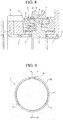
- Figs. 5 and 6 are views illustrating an example of a punching device (first device) in a manufacturing system for a ring-shaped member for a vehicle.
- a punching device 100 is configured to punch out an axial intermediate portion of the ring-shaped workpiece (workpiece) 25 entirely in the circumferential direction so that the first ring-shaped member 28A and the second ring-shaped member 28B each having at least one claw piece (15a, 15b) are formed.
- the punching device 100 includes a punch case 102, a cam slider 104, a mandrel 106, a punch 108, and a die 110.
- the punching device 100 includes three punches 108 arranged to be spaced apart from each other in the circumferential direction.
- the number of punches 108 can be other than three.
- One circumferential center of the punch 108 and another circumferential center thereof can have an angular interval (angular spacing) of 90° or more and less than 270°. This is advantageous, for example, for simultaneous punching operation using a plurality of punches by vector dispersion or the like.
- the three punches 108 are disposed at substantially equal pitch in the circumferential direction. A positional relationship of the three punches 108 has equiangular intervals (120° intervals).
- the plurality of punches can be disposed at non-regular intervals in the circumferential direction.
- the three punches 108 have substantially the same shape as each other.
- Each of the punches 108 can have a shape corresponding to three sides of the claw piece (15a, 15b) described above.
- the three punches 108 can have different shapes from each other.
- the punching device 100 performs a first punching process on a first region of the axial intermediate portion of the workpiece (the ring-shaped workpiece 25) in the circumferential direction.
- the cam slider 104, the punch 108, and the workpiece move in the axial direction with respect to the mandrel 106.
- An axial movement is converted in the radial direction by the cam slider 104 or the like.
- the three punches 108 arranged inside the workpiece simultaneously move outward in the radial direction. Three portions of the axial intermediate portion of the workpiece are simultaneously punched out by the three punches 108.
- Three blanks corresponding to a shape of the punch 108 are simultaneously formed in the workpiece and three claw pieces are formed as remainder portions. Simultaneous formation of the plurality of blanks is advantageous for improving positional accuracy of the claw pieces.
- the mandrel 106 can move in the axial direction with respect to the cam slider 104, the punch 108, and the workpiece.
- the punching device 100 performs a second punching process on a second region of the axial intermediate portion of the workpiece (the ring-shaped workpiece 25) in the circumferential direction.
- the workpiece is set such that the workpiece is inverted upside down with respect to the first punching process and shifted in the circumferential direction (for example, shifted by 60°).
- the three punches 108 used in the first punching process are also used in the second punching process. Excepting the setting of the workpiece, the second punching process can be performed in the same manner as the first punching process.
- the second punching process is performed so that the plurality of blanks formed by the first punching process are connected to each other and a blank (gap) which is continuous throughout in the circumferential direction is formed.
- a blank which is continuous throughout in the circumferential direction is formed.
- the axial intermediate portion of the workpiece is punched entirely in the circumferential direction and another three claw pieces are formed as remainder portions. Since a continuous blank (gap) is formed over the entire circumferential direction, the workpiece is separated into two pieces. Two ring-shaped members (the first ring-shaped member 28A and the second ring-shaped member 28B) each having three claw pieces (15a, 15b) are formed.
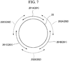
- Fig. 7 is a view schematically illustrating an example of punching regions.
- a punching region (a first region 201) in the first punching process includes a plurality of segmented regions 201A, 201B, and 201C which are spaced apart from each other in the circumferential direction.
- a punching region (a second region 202) in the second punching process includes a plurality of segmented regions 202A, 202B, and 202C which are spaced apart from each other in the circumferential direction.
- the second region 202 is shifted by 60° in the circumferential direction with respect to the first region 201. Also, in the example of Fig.
- the second region 202 in the circumferential direction partially overlaps the first region 201 in the circumferential direction.
- a sum of a circumferential length of punching in each step is larger than the circumferential length of the workpiece.
- one end portion of the punching region (for example, the segmented region 201A) in one punching step overlaps a punching region (for example, the segmented region 202A) in another punching step, and the other end portion of the punching region (for example, the segmented region 201A) in the one punching step overlaps a punching region (for example, the segmented region 202C) in another punching step. That is, both ends of a punching region in a certain step overlap two punching regions in another punching step (one or two steps). Due to the overlapping of the punching regions, continuous blanks are reliably formed.
- one cut out from a solid wire rod is used as the raw material.
- the raw material it is also possible to employ one cut out from a hollow wire rod. Even when the raw material obtained by cutting out such a hollow wire rod is used, it is possible to obtain an effect on the yield of the metal materials as in each example of the above-described embodiment.
- the present invention can be applied to various ring-shaped members for a vehicle having claw pieces on an end surface in the axial direction.
- an inclination angle of the claw piece included in the ring-shaped member which is an object of the present invention is not limited to the structure of each example of the above-described embodiment.
- the ring-shaped member which is an object of the present invention may be a finished product or an intermediate member (intermediate part) in a step of manufacturing the finished product.
- a method of manufacturing a ring-shaped member for a vehicle includes a punching step of punching out an axial intermediate portion (29) of a ring-shaped workpiece (25) so that a first ring-shaped member (25A) and a second ring-shaped member (25B) each having at least one claw piece (15a, 15b) are formed, in which the punching step includes a step of performing a first punching process on a first region of the intermediate portion (29) in a circumferential direction, and a step of performing a second punching process on a second region of the intermediate portion (29) which is at least partially different from the first region in the circumferential direction, and the method further includes a step of forming a concave surface (26) extending in the circumferential direction on an inner circumference of the intermediate portion (29) before the punching process.
- the concave surface (26) can contribute to processability of the punching process.
- the intermediate portion (29) can be punched out entirely in the circumferential direction.
- the remainder portion can be cut by a process other than the punching process.
- the concave arcuate portion (concave surface) 26 can be formed in the circumferential direction over the entire inner circumference of the intermediate portion (29).
- the concave surface (26) can be formed in a portion of the inner circumference of the intermediate portion (29) in the circumferential direction.
- the method in a method of manufacturing a ring-shaped member for a vehicle including cylindrical portion (13a, 13b) and a claw piece (15a, 15b) formed on an end surface in an axial direction of the cylindrical portion in a state of protruding in the axial direction from the end surface in the axial direction, the method includes a step of forming a pair of ring-shaped members (28A and 28B) in which at least one claw piece (15a, 15b) protruding in the axial direction from the end surface is provided on the end surface of each punched side by applying a punching process for punching out the entire circumference of an axial intermediate portion (29) with respect to a first ring-shaped workpiece (25).
- the punching process can be performed while index-rotating the first ring-shaped workpiece (25) and the punch relatively.
- the ring-shaped workpiece (24) can be formed by forging a material cut out from a solid wire rod.
- an inner circumferential surface and an outer circumferential surface of the first ring-shaped workpiece (25) can be inclined in a direction in which an outer diameter and an inner diameter become larger toward the axial center portion.
- a ring-shaped large-diameter workpiece (31) and a ring-shaped small-diameter workpiece (32) having outer and inner diameter dimensions different from each other are formed by forging the workpiece, and each of the ring-shaped large-diameter workpiece and the ring-shaped small-diameter workpiece can be the ring-shaped workpiece.
- the ring-shaped large-diameter workpiece (31) and the ring-shaped small-diameter workpiece (32) can have the same volume.
- a first ring-shaped workpiece (25a) formed by applying a rolling process to a ring-shaped workpiece formed from the ring-shaped large-diameter workpiece (31) and a first ring-shaped workpiece (25b) formed by applying a rolling process to a ring-shaped workpiece formed from the ring-shaped small-diameter workpiece (32) can have the same dimension.
- one cut out from a hollow wire rod can be the ring-shaped workpiece.
Landscapes
- Engineering & Computer Science (AREA)
- Mechanical Engineering (AREA)
- General Engineering & Computer Science (AREA)
- Mechanical Operated Clutches (AREA)
- Punching Or Piercing (AREA)
- Forging (AREA)
Abstract
Description
- The present invention relates to a method and a system for manufacturing a ring-shaped member for a vehicle having a claw piece such as a synchronizer ring incorporated in a manual transmission.
- Priority is claimed on Japanese Patent Application No.
2015-245271, filed December 16, 2015 - A synchronization mechanism is incorporated in a manual transmission so that a drive shaft rotates in synchronism with a transmission gear at the time of a gear shift operation. A synchronizer ring is incorporated in such a synchronization mechanism. As an example of the synchronization mechanism incorporating such a
synchronizer ring 1, a double-cone type thereof described inPatent Document 1 is illustrated inFig. 8 . In a synchronization mechanism, an insert spring 4 is mounted on an outer circumference of a synchronizing hub 3 which rotates together with adrive shaft 2, and acoupling sleeve 5 displaced in an axial direction on the basis of an operation of a shift lever is engaged with the insert spring 4. Anouter balk ring 8, asynchronizer ring 1, and aninner balk ring 9 are provided between thecoupling sleeve 5 and aclutch gear 7 which rotates in synchronism with atransmission gear 6. - When the
coupling sleeve 5 is pushed to the left inFig. 8 in accordance with a gear shift operation, first, a rotational speed difference between thecoupling sleeve 5 and theclutch gear 7 is eliminated by a frictional force acting between anouter balk ring 8 and thesynchronizer ring 1 and between thesynchronizer ring 1 and aninner balk ring 9. When thecoupling sleeve 5 is further pushed from this state, aspline groove 10 formed on an inner circumferential surface of thecoupling sleeve 5 engages with aspline groove 11 formed on an outer circumferential edge of theclutch gear 7 and aspline groove 12 formed on an outer circumferential edge of the insert spring 4 so as to stretch over them, and thus thedrive shaft 2 rotates in synchronism with thetransmission gear 6. - The
synchronizer ring 1 incorporated in the synchronization mechanism configured and operating as described above is configured in a shape, for example, as illustrated inFigs. 9 and10 . That is, thesynchronizer ring 1 is constituted by a taperedcylindrical portion 13 of which a diameter changes in the axial direction, andclaw pieces side end surface 14 of the taperedcylindrical portion 13. A thickness dimension t of each of theclaw pieces claw pieces synchronizer ring 1 is to be incorporated, and may be inclined in the same direction as the taperedcylindrical portion 13, or theclaw pieces - As a method of manufacturing the
synchronizer ring 1 having such a shape, a method of manufacturing thesynchronizer ring 1 at low cost by subjecting a flat metal plate to press processing is described inPatent Document 1.Figs. 11 to 15 illustrate a manufacturing method of a synchronizer ring described inPatent Document 1 and conventionally known. First, a first ring-shaped workpiece 16 as illustrated inFigs. 12 and 13 is formed by so-called blanking which punches out a flat metal plate such as carburized steel such as SCr420. The first ring-shaped workpiece 16 includes an annularmain body portion 17 and tongue-shaped portions main body portion 17. Next, a second ring-shaped workpiece 19 as illustrated inFigs. 14 and 15 is formed by press-molding the first ring-shaped workpiece 16. That is, in the molding step, the main body portion 17 (Figs. 12 and 13 ) is formed into a taperedcylindrical portion 20 inclined in a direction in which a diameter thereof decreases with distance away from the tongue-shaped portions shaped workpiece 19 is formed. Next, an end surface of the taperedcylindrical portion 20 and each of the tongue-shaped portions shaped workpiece 19 are subjected to machining such as turning so that the taperedcylindrical portion 20 and each of the tongue-shaped portions shaped portions respective claw pieces cylindrical portion 20 to form the taperedcylindrical portion 13 so that thesynchronizer ring 1 is formed. Then, thesynchronizer ring 1 manufactured in this manner is shipped after performing a predetermined inspection. - Incidentally, in the case of the method of manufacturing the
synchronizer ring 1 described inPatent Document 1 as described above, onesynchronizer ring 1 is formed from the first ring-shaped workpiece 16 formed by applying a punching process to a flat metal plate. Therefore, there is room for improvement from a manufacturing efficiency perspective. -
Patent Document 1 Japanese Patent Application, Publication NoH03-297527 - An aspect of the present invention is directed to realizing a method and a system of manufacturing a ring-shaped member capable of improving manufacturing efficiency.
- A method of manufacturing a ring-shaped member for a vehicle according to one aspect of the present invention includes a punching step of punching out an axial intermediate portion of a ring-shaped workpiece entirely in a circumferential direction so that a first ring-shaped member and a second ring-shaped member each having at least one claw piece are formed, in which the punching step includes a step of performing a first punching process on a first region of the intermediate portion in the circumferential direction, and a step of performing a second punching process on a second region of the intermediate portion which is at least partially different from the first region in the circumferential direction.
- A method of manufacturing a ring-shaped member for a vehicle according to another aspect of the present invention includes a punching step of punching out an axial intermediate portion of a ring-shaped workpiece so that a first ring-shaped member and a second ring-shaped member each having at least one claw piece are formed, in which the punching step has a step of performing a first punching process on a first region of the intermediate portion in a circumferential direction, and a step of performing a second punching process on a second region of the intermediate portion which is at least partially different from the first region in the circumferential direction, and the method further includes a step of forming a concave surface extending in the circumferential direction on an inner circumference of the intermediate portion before the punching step.
- Another aspect of the present invention is a synchronizer ring manufactured using the above-described manufacturing method.
- A system of manufacturing a ring-shaped member for a vehicle according to another aspect of the present invention includes a first device which punches out an axial intermediate portion of a ring-shaped workpiece entirely in the circumferential direction so that a first ring-shaped member and a second ring-shaped member each having at least one claw piece are formed, in which the first device performs a first punching process on a first region of the intermediate portion in the circumferential direction, and a second punching process on a second region of the intermediate portion which is at least partially different from the first region in the circumferential direction.
- A system of manufacturing a ring-shaped member for a vehicle according to another aspect of the present invention includes a first device which punches out an axial intermediate portion of a ring-shaped workpiece so that a first ring-shaped member and a second ring-shaped member each having at least one claw piece are formed, the first device performing a first punching process on a first region of the intermediate portion in a circumferential direction and a second punching process on a second region of the intermediate portion which is at least partially different from the first region in the circumferential direction, and a second device which forms a concave surface extending in the circumferential direction on an inner circumference of the intermediate portion before the punching process of the first device.
- A method of manufacturing a ring-shaped member according to another aspect of the present invention has a target of a ring-shaped member including a cylindrical portion, and a claw piece formed on an axial end surface of the cylindrical portion in a state of protruding in the axial direction from the axial end surface. Such a manufacturing method includes a step of manufacturing a pair of ring-shaped members in which at least one claw piece protruding in the axial direction from an end surface is provided on the end surface of each punched side by the punching process for punching out the entire circumference of the axial intermediate portion with respect to a first ring-shaped workpiece. In such a punching process, the entire circumference of the axial intermediate portion of the first ring-shaped workpiece can be punched out at once or punched out by punching a plurality of times.
- In one example, it is possible to employ a configuration in which the punching process is performed while index-rotating the first ring-shaped workpiece and the punch relatively.
- In one example, it is possible to employ a configuration in which there is a step of forming the first ring-shaped workpiece by applying a rolling process for reducing a thickness of a ring-shaped workpiece with respect to the ring-shaped workpiece.
- In one example, it is possible to employ a configuration in which the ring-shaped workpiece is formed by forging a material cut out from a solid wire rod. For forging, various methods such as cold forging, hot forging, or warm forging can be employed, for example.
- In one example, it is possible to employ a configuration in which an inner circumferential surface and an outer circumferential surface of the first ring-shaped workpiece are inclined in a direction in which an outer diameter and an inner diameter become larger toward the axial center portion.
- In one example, it is possible to employ a configuration in which a ring-shaped large-diameter workpiece and a ring-shaped small-diameter workpiece having different outer and inner diameters from each other are formed by forging the workpieces, and each of the ring-shaped large-diameter workpiece and the ring-shaped small-diameter workpiece are used as ring-shaped workpieces.
- In one example, it is possible to employ a configuration in which the ring-shaped large-diameter workpiece and the ring-shaped small-diameter workpiece have the same volume.
- In one example, it is possible to employ a configuration in which a first ring-shaped workpiece formed by applying a rolling process to a ring-shaped workpiece formed from the ring-shaped large-diameter workpiece and a first ring-shaped workpiece formed by applying a rolling process to a ring-shaped workpiece formed from the ring-shaped small-diameter workpiece have the same dimensions.
- In one example, it is possible to employ a configuration in which the workpiece is one cut out from a hollow wire rod.
- According to aspects of the present invention, it is possible to improve manufacturing efficiency of the ring-shaped member for a vehicle. For example, a pair of ring-shaped members can be formed from a first ring-shaped workpiece. Therefore, manufacturing efficiency can be improved compared to a manufacturing method in which one ring-shaped member is formed from one ring-shaped workpiece.
-
-
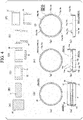
Fig. 1 is a view illustrating a first example of an embodiment of the present invention for describing steps of a method of manufacturing a ring-shaped member. -
Fig. 2 includes a perspective view (A) of a first ring-shaped workpiece illustrated inFig. 1(E) and a perspective view (B) of a pair of ring-shaped members illustrated inFig. 1(F) . -
Fig. 3 is a view for describing an example of a punching process, and is a perspective view of a first ring-shaped workpiece in a state in which a portion is punched out. -
Fig. 4 is a view similar toFig. 1 illustrating a second example of the embodiment of the present invention. -
Fig. 5 is a view illustrating an example of a punching device. -
Fig. 6 is a view illustrating an example of a punching device. -
Fig. 7 is a view schematically illustrating an example of punching regions. -
Fig. 8 is a partial cross-sectional view illustrating an example of a synchronization mechanism incorporating a synchronizer ring, which is one type of steel ring-shaped member. -
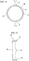
Fig. 9 is an end surface view illustrating an example of a synchronizer ring. -
Fig. 10 is a cross-sectional view taken along line A-A ofFig. 9 . -
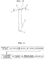
Fig. 11 is a flowchart illustrating an example of a conventional method. -
Fig. 12 is an end surface view of a first workpiece. -
Fig. 13 is a cross-sectional view taken along line B-B ofFig. 12 . -
Fig. 14 is an end surface view of a second workpiece. -
Fig. 15 is a cross-sectional view taken along line C-C ofFig. 14 . - A first example of an embodiment of the present invention will be described with reference to
Figs. 1 to 3 . In this example, a method of manufacturing a ring-shaped member of the present invention is applied to a synchronizer ring. Further, the synchronizer ring which is an object of the manufacturing method of the present example can be applied not only to a synchronization mechanism illustrated inFig. 8 but also to various synchronization mechanisms appropriately. Description of a structure of the synchronization mechanism will be omitted. Hereinafter, after describing the structure of the synchronizer ring which is an object of the manufacturing method of the present example, the method of manufacturing the ring-shaped member of the present example will be described. - In one example, as illustrated in
Figs. 1 to 3 , asynchronizer ring 1a (1b) includes a tapered cylindrical portion (a tubular portion, a truncated-cone like tube) 13a (13b), and a plurality ofclaw pieces 15a (15b) (three in the present example). - The tapered
cylindrical portion 13a (13b) includes a tubular portion (a tapered tubular portion (taper tube)) in which a diameter of an inner circumferential surface and/or an outer circumferential surface decreases toward one end edge in an axial direction, a conical tubular portion (cone tube), and a partial conical surface (partial cone surface). For example, both the inner circumferential surface and the outer circumferential surface of the taperedcylindrical portion 13a (13b) are inclined in a direction in which an inner diameter and an outer diameter become larger toward one side in the axial direction {upper side (lower side) ofFig. 1(G) (b) }. - Each of the claw pieces (tags) 15a (15b) is formed in a state of extending toward one side in the axial direction from a large diameter
side end surface 14a (14b) (end surface in the axial direction, one end surface in the axial direction) of the taperedcylindrical portion 13a (13b). In the present example, threeclaw pieces 15a (15b) are disposed at regular intervals in the circumferential direction on theaxial end surface 14a (14b). In another example, a plurality of claw pieces can be disposed at non-regular intervals in the circumferential direction. In another example, the number of claw pieces can be other than three. In the present example, each of theclaw pieces 15a (15b) includes a first side and a second side extending at least in the axial direction from theaxial end surface 14a, and a third side extending in the circumferential direction. The first side and the second side are disposed to be spaced apart in the circumferential direction. The third side connects an end of the first side and an end of the second side. Further, an angle (inclination angle) of each of theclaw pieces - Next, a method of manufacturing the
synchronizer ring 1a by the method of manufacturing the ring-shaped member of the present example will be described. - In the method of manufacturing the ring-shaped member of the present example, first, a coil-shaped (or long rod-shaped) solid wire rod made of chromium steel such as SCr420, chromium molybdenum steel such as SCM420, high carbon chromium bearing steel such as SUJ2, or the like is cut into a desired length by an appropriate method such as pressing, saw cutting, laser cutting, or the like to obtain a columnar raw material (billet) 20 illustrated in
Fig. 1(A) . In another example, another material can be used. - Next, the
raw material 20 is subjected to an upsetting process to form a columnarfirst workpiece 21 as illustrated inFig. 1(B) having a smaller axial dimension and a larger radial dimension (diameter) than those of theraw material 20. The upsetting process is performed by forging. - Next, the
first workpiece 21 is subjected to a backward extrusion process to form asecond workpiece 22 having a bottomed cylindrical shape as illustrated inFig. 1(C) . The backward extrusion process also is performed by forging. - Next, by applying a punching process to the
second workpiece 22, abottom portion 23 of thesecond workpiece 22 is punched out to form a ring-shapedworkpiece 24 as illustrated inFig. 1(D) . The ring-shapedworkpiece 24 has a cylindrical shape in which an inner diameter and an outer diameter do not change in the axial direction. - Next, by applying a rolling process to the ring-shaped
workpiece 24, inner and outer circumferential surfaces of the ring-shapedworkpiece 24 are plastically deformed, by a pair of rollers (not illustrated), into a shape matching circumferential surfaces of both rollers, and thereby a first ring-shapedworkpiece 25 as illustrated inFig. 1(E) is formed. During such a rolling process, the outer diameter and inner diameter of the ring-shapedworkpiece 24 increase, and a thickness of the ring-shapedworkpiece 24 decreases. - In one example, an outer circumferential surface of the first ring-shaped
workpiece 25 has a largest outer diameter at anaxial center portion 29 and has a smaller outer diameter toward both end sides in the axial direction. On the other hand, an inner circumferential surface of the first ring-shapedworkpiece 25 has a concavearcuate portion 26 formed at an axial intermediate portion including theaxial center portion 29, and inclinedcurved surface portions arcuate portion 26. Specifically, the concavearcuate portion 26 is formed to have a largest inner diameter at a portion corresponding to theaxial center portion 29 and to have a smaller inner diameter toward both end sides in the axial direction. The concave arcuate portion (concave surface) 26 continuously extending in the circumferential direction is formed on an inner circumferential surface of the axial center portion (axial intermediate portion) 29 of the first ring-shapedworkpiece 25. That is, a step of forming the concave surface extending in the circumferential direction on the inner circumference of theintermediate portion 29 is performed before a punching step to be described below. In one example, the concave arcuate portion (concave surface) 26 can be formed in the circumferential direction over the entire inner circumference of theintermediate portion 29. In another example, the concave arcuate portion (concave surface) 26 can be formed in a portion of the inner circumference of theintermediate portion 29 in the circumferential direction. On the other hand, each of the inclinedcurved surface portions workpiece 25 in the radial direction is formed such that a thickness dimension of a portion corresponding to the concavearcuate portion 26 is smaller than a thickness dimension of portions corresponding to each of the inclinedcurved surface portions workpiece 25 having such a configuration as described above has a symmetrical shape (symmetrical with respect to a virtual plane α which is perpendicular to the central axis of the first ring-shapedworkpiece 25 and passing through the axial center portion 29) with respect to the axial direction {vertical direction inFig. 1(E)(b) }. - Next, a central band-shaped portion 30 (the
axial center portion 29, intermediate portion) corresponding to a portion in which the concavearcuate portion 26 is formed in the first ring-shapedworkpiece 25 is subjected to a punching process to form a pair of ring-shaped members (a first ring-shapedmember 28A and a second ring-shapedmember 28B) as illustrated inFigs. 1(F) and2(B) . In one example, the punching step includes a step of performing a first punching process on a first region of the central band-shaped portion 30 (theaxial center portion 29, the intermediate portion) in the circumferential direction, and a step of performing a second punching process on a second region of the central band-shapedportion 30 which is at least partially different from the first region in the circumferential direction. The first punching process is performed such that at least one claw piece (15a, 15b) is formed. The second punching process is performed such that at least another one claw piece (15a, 15b) is formed. The first region includes a formation region for at least one claw piece (15a, 15b). The second region includes a formation region for at least one claw piece (15a, 15b). The second region in the circumferential direction can partially overlap the first region in the circumferential direction. A punching tool (for example, a punch) for the punching process can have a shape which corresponds to the three sides of the claw pieces (15a, 15b). A punching tool (for example, a punch) used in a first punching process can have substantially the same shape as a punching tool (for example, a punch) used in a second punching process. Alternatively, the punching tool (for example, a punch) used in the first punching process may have a different shape from the punching tool (for example, a punch) used in the second punching process. Alternatively, a punching tool (for example, a punch) used in the first punching process can also be used (re-used, shared) in the second punching process. - Specifically, for example, as illustrated in
Fig. 3 , a region of a span of approximately 1/6 (central angle of about 60°) of the entire circumference in the central band-shapedportion 30 is punched from a radially outward side to a radially inward side (or from the radially inward side to the radially outward side). Thereby, oneclaw piece 15b is formed on (a portion corresponding to) one axial end surface of the second ring-shapedmember 28B (seeFig. 2(B) ). That is, in the above region, a portion that has not been punched out by the punching process remains as theclaw piece 15b. Next, a region in which the central band-shapedportion 30 is punched out is shifted by 1/6 (central angle of about 60°) of the entire circumference of the first ring-shapedworkpiece 25 from the above-described position to one side in the circumferential direction (for example, in a direction indicated by an arrow β inFig. 3 ), and a region having the same span as that of the previous time is punched out at a position different from the previous time. Thereby, although not illustrated, theclaw piece 15a is formed on (a portion corresponding to) one axial end surface of the first ring-shapedmember 28A (seeFig. 2(B) ). By repeating such punching work (in a case of the present example, by performing punching six times in total), the first ring-shapedmember 28A having theclaw pieces 15a and the second ring-shapedmember 28B having theclaw pieces 15b are formed. Specifically, the first ring-shapedmember 28A in which threeclaw pieces 15a arranged at regular intervals (at 120° intervals in the case of the present example) in the circumferential direction are formed on the one axial end surface, and the second ring-shapedmember 28B in which threeclaw pieces 15b arranged at regular intervals (at 120° intervals in the case of the present example) in the circumferential direction are formed on the one axial end surface are formed. In this manner, by punching out the central band-shaped portion 30 (theaxial center portion 29, intermediate portion) of the first ring-shapedworkpiece 25 over the entire circumference, the pair of ring-shaped members (the first ring-shapedmember 28A and the second ring-shapedmember 28B) are formed. In other words, a portion of the first ring-shapedworkpiece 25 punched out by the above-described punching process is continuous over the entire circumference. By the step of punching out the axial intermediate portion of the ring-shapedworkpiece 25 entirely in the circumferential direction such that a continuous blank is formed throughout in the circumferential direction, the first ring-shapedmember 28A and the second ring-shapedmember 28B each having at least one claw piece are formed. In the first ring-shapedworkpiece 25, portions which have not been punched out in the punching process are a pair of ring-shaped members (the first ring-shapedmember 28A and the second ring-shapedmember 28B). - In one example, a manufacturing system for a ring-shaped member for a vehicle includes a punching device (first device) which punches out the axial intermediate portion of the ring-shaped
workpiece 25 entirely in the circumferential direction so that the first ring-shapedmember 28A and the second ring-shapedmember 28B each having at least one claw piece are formed. Also, the manufacturing system includes a processing device (second device) which forms the concave surface extending in the circumferential direction on an inner circumference of the intermediate portion before the punching process of the punching device. The punching device performs a first punching process on the first region of the intermediate portion in the circumferential direction, and performs a second punching process on the second region of the intermediate portion which is at least partially different from the first region in the circumferential direction. The punching device can have a punching tool (for example, a punch) configured such that at least one claw piece is formed by a single punching operation with respect to the intermediate portion using the punching device. In one example, the punching tool used in the first punching process may have substantially the same shape as the punching tool used in the second punching process. Alternatively, the punching tool used in the first punching process can also be used in the second punching process. - The punching process as described above can be performed using, for example, an indexing device and a punch. Specifically, the first ring-shaped
workpiece 25 supported by the indexing device is intermittently rotated at a predetermined angle (central angle of 60° of the first ring-shaped workpiece 25) with respect to a punch disposed at a radially outward side (or at a radially inward side) of the first ring-shapedworkpiece 25. Then, in a state in which rotation by the indexing device is stopped, a portion of the central band-shapedportion 30 of the first ring-shapedworkpiece 25 facing a distal end surface of the punch is punched out by the punch. - Further, when the punching process is performed in the steps from
Fig. 1(E) to 1(F) , a region punched by a single punching process can be made larger than that in the present example. For example, it is also possible to employ a configuration in which a region of about 1/3 (central angle of about 120°) of the entire circumference of the central band-shapedportion 30 is punched out from the radially outward side to the radially inward side (or from the radially inward side to the radially outward side) by a single punching process. In this case, oneclaw piece 15a is formed on the one ring-shaped member 28 and oneclaw piece 15a is formed on the other ring-shaped member 28 by the single punching process. Thereafter, by performing the punching operation three times in all by shifting the portion to be punched by 120°, it is possible to punch out the central band-shapedportion 30 over the entire circumference. - Also, it is also possible to employ a configuration in which a plurality of positions (for example, two positions spaced apart in the circumferential direction, each having a region of a central angle of 60°) spaced apart in the circumferential direction of the central band-shaped
portion 30 of the first ring-shapedworkpiece 25 are punched at the same time by a single punching process. In one example, in the first punching process on the first region of the intermediate portion in the circumferential direction, the first region can include a plurality of segmented regions spaced apart from each other in the circumferential direction. In addition, in the second punching process on the second region of the intermediate portion in the circumferential direction, the second region can include a plurality of segmented regions spaced apart from each other in the circumferential direction. The first device in the manufacturing system can include a plurality of punching tools (for example, punches) disposed to be spaced apart from each other in the circumferential direction. Such a punching process can be performed, for example, by a method called cam striking. - In the case of the present example, the ring-shaped members (the first ring-shaped
member 28A and the second ring-shapedmember 28B) correspond to the synchronizer rings (thesynchronizer ring 1a and thesynchronizer ring 1b). However, if necessary, it is also possible to form the synchronizer rings 1a and 1b by applying a finishing process such as sizing for adjusting shapes of the ring-shapedmembers members members members members - According to the method of manufacturing the ring-shaped member of the present example as described above, it is possible to improve manufacturing efficiency. That is, in the case of the method of manufacturing the ring-shaped member of the present example, the pair of ring-shaped
members synchronizer ring workpiece 25 made by applying a rolling process on the ring-shapedworkpiece 24. Therefore, manufacturing efficiency can be improved compared to the manufacturing method in which one ring-shaped member is formed from one ring-shaped workpiece. - In the case of the method of manufacturing the ring-shaped member of the present example, the ring-shaped
workpiece 24 is manufactured by forging having the processes as described above. That is, in the case of the method of manufacturing the ring-shaped member of the present example, an unused portion of metal materials is only a portion corresponding to thebottom portion 23 of thesecond workpiece 22 which is punched out in the punching steps illustrated inFigs. 1(C) and 1(D) . This portion is less than an unused portion of a flat plate in a case in which a flat metal plate is subjected to a punching process to form a member of the same shape as the ring-shapedworkpiece 24. Therefore, according to the manufacturing method of the present example, it is possible to reduce manufacturing cost by improving yield of metal materials. Further, since the metal wire rod used in the method of manufacturing the ring-shaped member of the present example is less expensive than a metal plate, manufacturing cost can be reduced. - Also, in the case of the present example, when the central band-shaped
portion 30 of the first ring-shapedworkpiece 25 is punched, theclaw piece 15a of one ring-shapedmember 28A and theclaw piece 15b of the other ring-shapedmembers 28B can be formed by the non-punched portion of the central band-shapedportion 30. Therefore, it is possible to reduce an amount of the unused portion (a portion which does not correspond to theclaw piece 15a of one ring-shapedmember 28A and theclaw piece 15b of the other ring-shapedmember 28B) in the central band-shapedportion 30. As a result, yield of the metal materials can be improved and manufacturing cost can be reduced. - Also, it is difficult to form a thin and large diameter member such as the first ring-shaped
workpiece 25 by a forging process, but it can be relatively easily formed when the rolling process as described above is used. As a result, it is possible to reduce processing costs, and further it is possible to reduce manufacturing costs. Particularly, in the case of the present example, a shape of the first ring-shapedworkpiece 25 is symmetrical with respect to the axial direction. Since such a shape facilitates a stable rolling process, it is possible to reduce processing costs, and further it is possible to reduce manufacturing costs. - A second example of the embodiment of the present invention will be described with reference to
Fig. 4 . In a method of manufacturing the ring-shaped member of the present example, steps of forming a ring-shaped large-diameter workpiece 31 corresponding to the ring-shaped workpiece and a member corresponding to a ring-shaped small-diameter workpiece 32 are different from the case of the above-described first example of the embodiment. - In the method of manufacturing the ring-shaped member of the present example, first, as in the first example of the embodiment described above, a coil-shaped (or long rod-shaped) wire rod made of chromium steel such as SCr420, chromium molybdenum steel such as SCM420, or high carbon chromium bearing steel such as
SUJ 2 is cut into a desired length by an appropriate method such as pressing, saw cutting, laser cutting, or the like to obtain a columnar raw material (billet) 20 illustrated inFig. 4(A) . In another example, another materials can be used. - Next, the
raw material 20 is subjected to an upsetting process to form a columnarfirst workpiece 21 as illustrated inFig. 4(B) having a smaller axial dimension and a larger radial dimension (diameter) than theraw material 20. The upsetting process is performed by forging. As forging, various methods such as cold forging, hot forging, or warm forging can be employed, for example. - Next, a
first workpiece 21 is subjected to a backward extrusion process to form asecond workpiece 22 having a bottomed cylindrical shape as illustrated inFig. 4(C) .
The backward extrusion process is performed by forging. - Next, by applying a punching process to the
second workpiece 22, abottom portion 23 of thesecond workpiece 22 is punched out to form athird workpiece 33 as illustrated inFig. 4(D) . Such athird workpiece 33 has a cylindrical shape in which an inner diameter and an outer diameter do not change in the axial direction. Thethird workpiece 33 corresponds to the ring-shapedworkpiece 24 of the first example of the above-described embodiment. Steps so far are the same as those in the first example of the above-described embodiment. - Particularly, in the case of the method of manufacturing the ring-shaped member of the present example, the
third workpiece 33 is subjected to a forward extrusion process to form afourth workpiece 34 having a stepped cylindrical shape on both inner and outer circumferential surfaces as illustrated inFig. 4(E) . - Next, the
fourth workpiece 34 is subjected to a punching process to be separated into the ring-shaped large-diameter workpiece 31 and the ring-shaped small-diameter workpiece 32 as illustrated inFig. 4(F) . Both of the ring-shaped large-diameter workpiece 31 and the ring-shaped small-diameter workpiece 32 are cylindrical members whose inner and outer diameters are not changed with respect to the axial direction. The inner diameter of the ring-shaped small-diameter workpiece 32 is smaller than the inner diameter of the ring-shaped large-diameter workpiece 31. The outer diameter of the ring-shaped small-diameter workpiece 32 is smaller than the outer diameter of the ring-shaped large-diameter workpiece 31. On the other hand, a volume of the ring-shaped large-diameter workpiece 31 and a volume of the ring-shaped small-diameter workpiece 32 are equal to each other. In the case of the present example, both the ring-shaped large-diameter workpiece 31 and the ring-shaped small-diameter workpiece 32 correspond to the ring-shaped workpiece. - Then, first, by applying a rolling process to the ring-shaped large-
diameter workpiece 31, inner and outer circumferential surfaces of the ring-shaped large-diameter workpiece 31 are plastically deformed, by a pair of rollers (not shown), into a shape matching circumferential surfaces of both rollers, and thereby a first ring-shapedworkpiece 25a as illustrated inFig. 4(G) is formed. The first ring-shapedworkpiece 25a has substantially the same structure as the first ring-shapedworkpiece 25 of the above-described first example of the embodiment. - On the other hand, by applying the rolling process also to the ring-shaped small-
diameter workpiece 32, a first ring-shapedworkpiece 25b as illustrated inFig. 4(G) is formed. That is, in the case of the present example, the first ring-shapedworkpieces diameter workpiece 31 and the ring-shaped small-diameter workpiece 32. - Further, a step of obtaining the pair of ring-shaped
members workpieces axial center portion 29 of the first ring-shapedworkpieces - In the case of the present example as described above, since it is possible to form four ring-shaped
members raw material 20, when the ring-shaped large-diameter workpiece 31 and the ring-shaped small-diameter workpiece 32 are formed, an unused portion of the metal materials is only a portion corresponding to thebottom portion 23 of thesecond workpiece 22 punched out in the steps fromFig. 4(C) to Fig. 4(D) . In the case of the present example as described above, it is possible to further improve manufacturing efficiency of the ring-shaped member and to further improve yield of metal materials, thereby manufacturing costs can be reduced. Other configurations, operations and effects are similar to those in the above-described first example of the embodiment. -
Figs. 5 and6 are views illustrating an example of a punching device (first device) in a manufacturing system for a ring-shaped member for a vehicle. As illustrated inFig. 5 , a punching device 100 is configured to punch out an axial intermediate portion of the ring-shaped workpiece (workpiece) 25 entirely in the circumferential direction so that the first ring-shapedmember 28A and the second ring-shapedmember 28B each having at least one claw piece (15a, 15b) are formed. In the examples ofFigs. 5 and6 , the punching device 100 includes apunch case 102, acam slider 104, amandrel 106, apunch 108, and adie 110. In one example, the punching device 100 includes threepunches 108 arranged to be spaced apart from each other in the circumferential direction. In another example, the number ofpunches 108 can be other than three. One circumferential center of thepunch 108 and another circumferential center thereof can have an angular interval (angular spacing) of 90° or more and less than 270°. This is advantageous, for example, for simultaneous punching operation using a plurality of punches by vector dispersion or the like. In one example, the threepunches 108 are disposed at substantially equal pitch in the circumferential direction. A positional relationship of the threepunches 108 has equiangular intervals (120° intervals). In another example, the plurality of punches can be disposed at non-regular intervals in the circumferential direction. In one example, the threepunches 108 have substantially the same shape as each other. Each of thepunches 108 can have a shape corresponding to three sides of the claw piece (15a, 15b) described above. In another example, the threepunches 108 can have different shapes from each other. - As illustrated in
Fig. 5(a) , the punching device 100 performs a first punching process on a first region of the axial intermediate portion of the workpiece (the ring-shaped workpiece 25) in the circumferential direction. As illustrated inFigs. 5 and6 , in the first punching process, thecam slider 104, thepunch 108, and the workpiece move in the axial direction with respect to themandrel 106. An axial movement is converted in the radial direction by thecam slider 104 or the like. The threepunches 108 arranged inside the workpiece simultaneously move outward in the radial direction. Three portions of the axial intermediate portion of the workpiece are simultaneously punched out by the threepunches 108. Three blanks corresponding to a shape of thepunch 108 are simultaneously formed in the workpiece and three claw pieces are formed as remainder portions. Simultaneous formation of the plurality of blanks is advantageous for improving positional accuracy of the claw pieces. In another example, themandrel 106 can move in the axial direction with respect to thecam slider 104, thepunch 108, and the workpiece. - Next, as illustrated in
Fig. 5(b) , the punching device 100 performs a second punching process on a second region of the axial intermediate portion of the workpiece (the ring-shaped workpiece 25) in the circumferential direction. In the second punching process, the workpiece is set such that the workpiece is inverted upside down with respect to the first punching process and shifted in the circumferential direction (for example, shifted by 60°). In one example, the threepunches 108 used in the first punching process are also used in the second punching process. Excepting the setting of the workpiece, the second punching process can be performed in the same manner as the first punching process. Also, the second punching process is performed so that the plurality of blanks formed by the first punching process are connected to each other and a blank (gap) which is continuous throughout in the circumferential direction is formed. As a result, the axial intermediate portion of the workpiece is punched entirely in the circumferential direction and another three claw pieces are formed as remainder portions. Since a continuous blank (gap) is formed over the entire circumferential direction, the workpiece is separated into two pieces. Two ring-shaped members (the first ring-shapedmember 28A and the second ring-shapedmember 28B) each having three claw pieces (15a, 15b) are formed. -
Fig. 7 is a view schematically illustrating an example of punching regions. A punching region (a first region 201) in the first punching process includes a plurality ofsegmented regions segmented regions Fig. 7 , thesecond region 202 is shifted by 60° in the circumferential direction with respect to thefirst region 201. Also, in the example ofFig. 7 , thesecond region 202 in the circumferential direction partially overlaps thefirst region 201 in the circumferential direction. In a plurality of punching steps, a sum of a circumferential length of punching in each step is larger than the circumferential length of the workpiece. In one example, one end portion of the punching region (for example, thesegmented region 201A) in one punching step overlaps a punching region (for example, thesegmented region 202A) in another punching step, and the other end portion of the punching region (for example, thesegmented region 201A) in the one punching step overlaps a punching region (for example, thesegmented region 202C) in another punching step. That is, both ends of a punching region in a certain step overlap two punching regions in another punching step (one or two steps). Due to the overlapping of the punching regions, continuous blanks are reliably formed. - In each example of the above-described embodiment, one cut out from a solid wire rod is used as the raw material. However, as the raw material, it is also possible to employ one cut out from a hollow wire rod. Even when the raw material obtained by cutting out such a hollow wire rod is used, it is possible to obtain an effect on the yield of the metal materials as in each example of the above-described embodiment.
- In addition to the synchronizer ring, the present invention can be applied to various ring-shaped members for a vehicle having claw pieces on an end surface in the axial direction.
- Further, an inclination angle of the claw piece included in the ring-shaped member which is an object of the present invention is not limited to the structure of each example of the above-described embodiment. Also, the ring-shaped member which is an object of the present invention may be a finished product or an intermediate member (intermediate part) in a step of manufacturing the finished product.
- In one embodiment, a method of manufacturing a ring-shaped member for a vehicle includes a punching step of punching out an axial intermediate portion (29) of a ring-shaped workpiece (25) so that a first ring-shaped member (25A) and a second ring-shaped member (25B) each having at least one claw piece (15a, 15b) are formed, in which the punching step includes a step of performing a first punching process on a first region of the intermediate portion (29) in a circumferential direction, and a step of performing a second punching process on a second region of the intermediate portion (29) which is at least partially different from the first region in the circumferential direction, and the method further includes a step of forming a concave surface (26) extending in the circumferential direction on an inner circumference of the intermediate portion (29) before the punching process. For example, the concave surface (26) can contribute to processability of the punching process. In one example, the intermediate portion (29) can be punched out entirely in the circumferential direction. In another example, after punching out the intermediate portion (29) leaving a portion in the circumferential direction, the remainder portion can be cut by a process other than the punching process. In one example, the concave arcuate portion (concave surface) 26 can be formed in the circumferential direction over the entire inner circumference of the intermediate portion (29). In another example, the concave surface (26) can be formed in a portion of the inner circumference of the intermediate portion (29) in the circumferential direction.
- In one embodiment, in a method of manufacturing a ring-shaped member for a vehicle including cylindrical portion (13a, 13b) and a claw piece (15a, 15b) formed on an end surface in an axial direction of the cylindrical portion in a state of protruding in the axial direction from the end surface in the axial direction, the method includes a step of forming a pair of ring-shaped members (28A and 28B) in which at least one claw piece (15a, 15b) protruding in the axial direction from the end surface is provided on the end surface of each punched side by applying a punching process for punching out the entire circumference of an axial intermediate portion (29) with respect to a first ring-shaped workpiece (25).
- In the above-described embodiment, the punching process can be performed while index-rotating the first ring-shaped workpiece (25) and the punch relatively.
- In the above-described embodiment, it is possible to have a step of forming the first ring-shaped workpiece (29) by applying a rolling process for reducing a thickness of a ring-shaped workpiece with respect to the ring-shaped workpiece (24). In one example, the ring-shaped workpiece (24) can be formed by forging a material cut out from a solid wire rod.
- In the above-described embodiment, an inner circumferential surface and an outer circumferential surface of the first ring-shaped workpiece (25) can be inclined in a direction in which an outer diameter and an inner diameter become larger toward the axial center portion. In one example, a ring-shaped large-diameter workpiece (31) and a ring-shaped small-diameter workpiece (32) having outer and inner diameter dimensions different from each other are formed by forging the workpiece, and each of the ring-shaped large-diameter workpiece and the ring-shaped small-diameter workpiece can be the ring-shaped workpiece. In one example, the ring-shaped large-diameter workpiece (31) and the ring-shaped small-diameter workpiece (32) can have the same volume.
- In the above-described embodiment, a first ring-shaped workpiece (25a) formed by applying a rolling process to a ring-shaped workpiece formed from the ring-shaped large-diameter workpiece (31) and a first ring-shaped workpiece (25b) formed by applying a rolling process to a ring-shaped workpiece formed from the ring-shaped small-diameter workpiece (32) can have the same dimension.
- In the above-described embodiment, one cut out from a hollow wire rod can be the ring-shaped workpiece.
-
- 1, 1a, 1b Synchronizer ring
- 2 Drive shaft
- 3 Synchronizing hub
- 4 Insert spring
- 5 Coupling sleeve
- 6 Transmission gear
- 7 Clutch gear
- 8 Outer balk ring
- 9 Inner balk ring
- 10 Spline groove
- 11 Spline groove
- 12 Spline groove
- 13, 13a, 13b Tapered cylindrical portion
- 14, 14a, 14b Large diameter side end surface
- 15, 15a, 15b Claw piece
- 16 First ring-shaped workpiece
- 17 Main body portion
- 18 Tongue-shaped portion
- 19 Second ring-shaped workpiece
- 19 Tapered cylindrical portion
- 20 Raw material
- 21 First workpiece
- 22 Second workpiece
- 23 Bottom portion
- 24 Ring-shaped workpiece
- 25, 25a, 25b First ring-shaped workpiece
- 26 Concave arcuate portion
- 27 Inclined curved surface portion
- 28, 28A, 28B Ring-shaped member
- 29 Axial center portion
- 30 Central band-shaped portion
- 31 Ring-shaped large-diameter workpiece
- 32 Ring-shaped small-diameter workpiece
- 33 Third workpiece
- 34 Fourth workpiece
- 100 Punching device
- 108 Punch (Punching tool)
- 201 First region
- 201A, 201B, 201C Segmented region
- 202 Second region
- 202A, 202B, 202C Segmented region
Claims (13)
- A method of manufacturing a ring-shaped member for a vehicle, the method comprising:punching out an axial intermediate portion of a ring-shaped workpiece entirely in a circumferential direction so that a first ring-shaped member and a second ring-shaped member each having at least one claw piece are formed, whereinthe punching step comprises:performing a first punching process on a first region of the intermediate portion in the circumferential direction; andperforming a second punching process on a second region of the intermediate portion which is at least partially different from the first region in the circumferential direction.
- The method of manufacturing a ring-shaped member for a vehicle according to claim 1, wherein:the first punching process is performed so that at least one claw piece is formed; andthe second punching process is performed so that at least another one claw piece is formed.
- The method of manufacturing a ring-shaped member for a vehicle according to claim 1 or 2, wherein:the first region includes a plurality of segmented regions spaced apart from each other in the circumferential direction; andthe second region includes a plurality of segmented regions spaced apart from each other in the circumferential direction.
- The method of manufacturing a ring-shaped member for a vehicle according to any one of claims 1 to 3, wherein a punching tool used in the first punching process has substantially the same shape as a punching tool used in the second punching process.
- The method of manufacturing a ring-shaped member for a vehicle according to any one of claims 1 to 4, further comprising forming a concave surface extending in the circumferential direction on an inner circumference of the intermediate portion before the punching step.
- A method of manufacturing a ring-shaped member for a vehicle, the method comprising:punching out an axial intermediate portion of a ring-shaped workpiece so that a first ring-shaped member and a second ring-shaped member each having at least one claw piece are formed, whereinthe punching step comprises:performing a first punching process on a first region of the intermediate portion in a circumferential direction; andperforming a second punching process on a second region of the intermediate portion which is at least partially different from the first region in the circumferential direction, andthe method further comprises forming a concave surface extending in the circumferential direction on an inner circumference of the intermediate portion before the punching step.
- A synchronizer ring manufactured using the manufacturing method according to any one of claims 1 to 6.
- A system of manufacturing a ring-shaped member for a vehicle, the system comprising:a first device configured to punch out an axial intermediate portion of a ring-shaped workpiece entirely in a circumferential direction so that a first ring-shaped member and a second ring-shaped member each having at least one claw piece are formed, whereinthe first device is configured to:perform a first punching process on a first region of the intermediate portion in the circumferential direction; andperform a second punching process on a second region of the intermediate portion which is at least partially different from the first region in the circumferential direction.
- The system of manufacturing a ring-shaped member for a vehicle according to claim 8, wherein the first device includes a punching tool configured to form at least one claw piece by a single punching operation using the punching device with respect to the intermediate portion.
- The system of manufacturing a ring-shaped member for a vehicle according to claim 8 or 9, wherein the second region in the circumferential direction partially overlaps the first region in the circumferential direction.
- The system of manufacturing a ring-shaped member for a vehicle according to claim 9 or 10, wherein:the first region includes a plurality of segmented regions spaced apart from each other in the circumferential direction;the second region includes a plurality of segmented regions spaced apart from each other in the circumferential direction; andthe first device includes a plurality of punching tools spaced apart from each other in the circumferential direction.
- The system of manufacturing a ring-shaped member for a vehicle according to any one of claims 9 to 11, wherein:the punching tool used in the first punching process has substantially the same shape as that of the punching tool used in the second punching process; andthe punching tool used in the first punching process is also used in the second punching process.
- A system of manufacturing a ring-shaped member for a vehicle, the system comprising:a first device configured to punch out an axial intermediate portion of a ring-shaped workpiece so that a first ring-shaped member and a second ring-shaped member each having at least one claw piece are formed, the first device being configured to perform a first punching process on a first region of the intermediate portion in a circumferential direction and a second punching process on a second region of the intermediate portion which is at least partially different from the first region in the circumferential direction; anda second device configured to form a concave surface extending in the circumferential direction on an inner circumference of the intermediate portion before the punching process of the first device.
Applications Claiming Priority (2)
| Application Number | Priority Date | Filing Date | Title |
|---|---|---|---|
| JP2015245271 | 2015-12-16 | ||
| PCT/JP2016/087543 WO2017104800A1 (en) | 2015-12-16 | 2016-12-16 | Method and system for producing ring-shaped member for vehicle, and synchronizer ring |
Publications (3)
| Publication Number | Publication Date |
|---|---|
| EP3318345A1 true EP3318345A1 (en) | 2018-05-09 |
| EP3318345A4 EP3318345A4 (en) | 2019-03-06 |
| EP3318345B1 EP3318345B1 (en) | 2023-05-24 |
Family
ID=59056721
Family Applications (1)
| Application Number | Title | Priority Date | Filing Date |
|---|---|---|---|
| EP16875774.8A Active EP3318345B1 (en) | 2015-12-16 | 2016-12-16 | Method and system for producing ring-shaped member for vehicle, and synchronizer ring |
Country Status (5)
| Country | Link |
|---|---|
| US (1) | US10369612B2 (en) |
| EP (1) | EP3318345B1 (en) |
| JP (2) | JP6256667B2 (en) |
| CN (1) | CN108367330A (en) |
| WO (1) | WO2017104800A1 (en) |
Family Cites Families (13)
| Publication number | Priority date | Publication date | Assignee | Title |
|---|---|---|---|---|
| US3259003A (en) * | 1964-06-26 | 1966-07-05 | American Radiator & Standard | Method and apparatus for forming openings in tubular members |
| US4621553A (en) * | 1984-05-30 | 1986-11-11 | Henry Gruchalski | Vertical pierce die |
| JPS62107830A (en) * | 1985-11-01 | 1987-05-19 | Ofic Co | Method and device for working automatically retainer |
| JPS63154226A (en) * | 1986-12-18 | 1988-06-27 | Yamaha Motor Co Ltd | Press piercing method for cylindrical material |
| JP2605376B2 (en) * | 1988-09-01 | 1997-04-30 | 日本精工株式会社 | Compound press machine |
| JPH0712509B2 (en) | 1990-04-17 | 1995-02-15 | 日本精工株式会社 | Outside ring manufacturing method |
| JPH049238A (en) * | 1990-04-27 | 1992-01-14 | Nippon Seiko Kk | How to manufacture outside rings |
| JP3667814B2 (en) * | 1995-04-18 | 2005-07-06 | 中西金属工業株式会社 | Synchronizer ring manufacturing method |
| JP3801588B2 (en) * | 2003-10-21 | 2006-07-26 | ユニプレス株式会社 | Work processing equipment |
| DE102006006024B4 (en) * | 2006-02-08 | 2013-12-12 | Ab Skf | Method of making rings |
| JP2015039716A (en) * | 2013-08-22 | 2015-03-02 | 新日鐵住金株式会社 | Burring processing method and burring processing apparatus |
| CN203508740U (en) * | 2013-10-23 | 2014-04-02 | 中山市奥美森工业有限公司 | Punch and punching device for punching tube walls of metal circular tubes |
| CN203955860U (en) * | 2014-08-02 | 2014-11-26 | 徐益红 | Round type perforating die |
-
2016
- 2016-12-16 JP JP2017533046A patent/JP6256667B2/en not_active Expired - Fee Related
- 2016-12-16 CN CN201680072825.1A patent/CN108367330A/en active Pending
- 2016-12-16 EP EP16875774.8A patent/EP3318345B1/en active Active
- 2016-12-16 US US15/748,901 patent/US10369612B2/en active Active
- 2016-12-16 WO PCT/JP2016/087543 patent/WO2017104800A1/en not_active Ceased
-
2017
- 2017-12-06 JP JP2017234695A patent/JP6822387B2/en active Active
Also Published As
| Publication number | Publication date |
|---|---|
| JP6256667B2 (en) | 2018-01-10 |
| EP3318345B1 (en) | 2023-05-24 |
| EP3318345A4 (en) | 2019-03-06 |
| US10369612B2 (en) | 2019-08-06 |
| WO2017104800A1 (en) | 2017-06-22 |
| JP6822387B2 (en) | 2021-01-27 |
| JPWO2017104800A1 (en) | 2017-12-21 |
| CN108367330A (en) | 2018-08-03 |
| US20180214925A1 (en) | 2018-08-02 |
| JP2018043291A (en) | 2018-03-22 |
Similar Documents
| Publication | Publication Date | Title |
|---|---|---|
| JP5309690B2 (en) | Manufacturing method of inner and outer rings of rolling bearing | |
| US5125256A (en) | Method of manufacturing outside ring | |
| KR101910395B1 (en) | Method and device for reshaping a workpice | |
| CN104722701A (en) | Method and device for producing hollow shaft through radial deformation, and hollow shaft | |
| EP2769781B1 (en) | A cold rolling method for forming bearing rings | |
| JP6641903B2 (en) | Method for manufacturing ring-shaped member | |
| US20100068428A1 (en) | Method for Producing Hollow Shaft Base Bodies and Hollow Shaft Base Body Produced Thereby | |
| CN114535471B (en) | Multi-roller flexible near-net composite rolling forming method for thin-walled rings with sudden profile | |
| JP5863270B2 (en) | Method for manufacturing ring shaped material | |
| CN105992660B (en) | The manufacturing method of endless member | |
| EP3318345B1 (en) | Method and system for producing ring-shaped member for vehicle, and synchronizer ring | |
| CN110842120B (en) | Rolling and rotary forming method for large-taper complex special-shaped ring disc type component | |
| US11951527B2 (en) | Method for producing a ball raceway on a workpiece and a ball screw nut having a ball raceway thus produced | |
| JP2009131874A (en) | Method for producing ring product having annular groove on outer diameter surface by controlling fiber flow in rolling | |
| US8701454B2 (en) | Flow form tool mandrel | |
| JP2007130673A (en) | Method of manufacturing outer race and inner race of bearing race using bearing steel pipe | |
| JP2017030023A (en) | Manufacturing method of differential ring gear | |
| JP5919746B2 (en) | Manufacturing method of bearing race | |
| RU2686503C1 (en) | Method for combined pipe ends upsetting | |
| RU2392078C1 (en) | Method of manufacturing pipes with flanges | |
| JP2001129631A (en) | Method of manufacturing shaft with large diameter flange | |
| JPH049238A (en) | How to manufacture outside rings | |
| KR20150011866A (en) | Method for manufacturing outer race for one-way clutch | |
| WO2014188838A1 (en) | Method for producing outside joint member for use in constant-velocity universal joint, and intermediate forged product to be made into outside joint member | |
| JP5188283B2 (en) | Manufacturing method of ring product having annular groove on inner diameter surface by controlling fiber flow in rolling |
Legal Events
| Date | Code | Title | Description |
|---|---|---|---|
| STAA | Information on the status of an ep patent application or granted ep patent |
Free format text: STATUS: THE INTERNATIONAL PUBLICATION HAS BEEN MADE |
|
| PUAI | Public reference made under article 153(3) epc to a published international application that has entered the european phase |
Free format text: ORIGINAL CODE: 0009012 |
|
| STAA | Information on the status of an ep patent application or granted ep patent |
Free format text: STATUS: REQUEST FOR EXAMINATION WAS MADE |
|
| 17P | Request for examination filed |
Effective date: 20180130 |
|
| AK | Designated contracting states |
Kind code of ref document: A1 Designated state(s): AL AT BE BG CH CY CZ DE DK EE ES FI FR GB GR HR HU IE IS IT LI LT LU LV MC MK MT NL NO PL PT RO RS SE SI SK SM TR |
|
| AX | Request for extension of the european patent |
Extension state: BA ME |
|
| A4 | Supplementary search report drawn up and despatched |
Effective date: 20190205 |
|
| RIC1 | Information provided on ipc code assigned before grant |
Ipc: B21D 53/26 20060101ALI20190130BHEP Ipc: B21K 1/30 20060101ALI20190130BHEP Ipc: B21D 53/16 20060101ALI20190130BHEP Ipc: B21D 28/28 20060101AFI20190130BHEP Ipc: F16D 23/02 20060101ALI20190130BHEP Ipc: B21D 53/84 20060101ALI20190130BHEP Ipc: B21D 28/02 20060101ALI20190130BHEP Ipc: B21D 28/00 20060101ALI20190130BHEP |
|
| DAV | Request for validation of the european patent (deleted) | ||
| DAX | Request for extension of the european patent (deleted) | ||
| STAA | Information on the status of an ep patent application or granted ep patent |
Free format text: STATUS: EXAMINATION IS IN PROGRESS |
|
| 17Q | First examination report despatched |
Effective date: 20191119 |
|
| REG | Reference to a national code |
Ref country code: DE Ref legal event code: R079 Ref document number: 602016079640 Country of ref document: DE Free format text: PREVIOUS MAIN CLASS: B21D0028280000 Ipc: B21D0028300000 |
|
| GRAP | Despatch of communication of intention to grant a patent |
Free format text: ORIGINAL CODE: EPIDOSNIGR1 |
|
| STAA | Information on the status of an ep patent application or granted ep patent |
Free format text: STATUS: GRANT OF PATENT IS INTENDED |
|
| RIC1 | Information provided on ipc code assigned before grant |
Ipc: B21D 28/30 20060101AFI20221206BHEP |
|
| INTG | Intention to grant announced |
Effective date: 20221219 |
|
| RIN1 | Information on inventor provided before grant (corrected) |
Inventor name: YASUDA, YUU Inventor name: KOYAMA, HIROSHI Inventor name: KOBAYASHI, KAZUTO |
|
| GRAS | Grant fee paid |
Free format text: ORIGINAL CODE: EPIDOSNIGR3 |
|
| GRAA | (expected) grant |
Free format text: ORIGINAL CODE: 0009210 |
|
| STAA | Information on the status of an ep patent application or granted ep patent |
Free format text: STATUS: THE PATENT HAS BEEN GRANTED |
|
| AK | Designated contracting states |
Kind code of ref document: B1 Designated state(s): AL AT BE BG CH CY CZ DE DK EE ES FI FR GB GR HR HU IE IS IT LI LT LU LV MC MK MT NL NO PL PT RO RS SE SI SK SM TR |
|
| REG | Reference to a national code |
Ref country code: GB Ref legal event code: FG4D |
|
| REG | Reference to a national code |
Ref country code: CH Ref legal event code: EP |
|
| REG | Reference to a national code |
Ref country code: DE Ref legal event code: R096 Ref document number: 602016079640 Country of ref document: DE |
|
| REG | Reference to a national code |
Ref country code: AT Ref legal event code: REF Ref document number: 1569207 Country of ref document: AT Kind code of ref document: T Effective date: 20230615 |
|
| REG | Reference to a national code |
Ref country code: IE Ref legal event code: FG4D |
|
| REG | Reference to a national code |
Ref country code: LT Ref legal event code: MG9D |
|
| REG | Reference to a national code |
Ref country code: NL Ref legal event code: MP Effective date: 20230524 |
|
| REG | Reference to a national code |
Ref country code: AT Ref legal event code: MK05 Ref document number: 1569207 Country of ref document: AT Kind code of ref document: T Effective date: 20230524 |
|
| PG25 | Lapsed in a contracting state [announced via postgrant information from national office to epo] |
Ref country code: SE Free format text: LAPSE BECAUSE OF FAILURE TO SUBMIT A TRANSLATION OF THE DESCRIPTION OR TO PAY THE FEE WITHIN THE PRESCRIBED TIME-LIMIT Effective date: 20230524 Ref country code: PT Free format text: LAPSE BECAUSE OF FAILURE TO SUBMIT A TRANSLATION OF THE DESCRIPTION OR TO PAY THE FEE WITHIN THE PRESCRIBED TIME-LIMIT Effective date: 20230925 Ref country code: NO Free format text: LAPSE BECAUSE OF FAILURE TO SUBMIT A TRANSLATION OF THE DESCRIPTION OR TO PAY THE FEE WITHIN THE PRESCRIBED TIME-LIMIT Effective date: 20230824 Ref country code: NL Free format text: LAPSE BECAUSE OF FAILURE TO SUBMIT A TRANSLATION OF THE DESCRIPTION OR TO PAY THE FEE WITHIN THE PRESCRIBED TIME-LIMIT Effective date: 20230524 Ref country code: ES Free format text: LAPSE BECAUSE OF FAILURE TO SUBMIT A TRANSLATION OF THE DESCRIPTION OR TO PAY THE FEE WITHIN THE PRESCRIBED TIME-LIMIT Effective date: 20230524 Ref country code: AT Free format text: LAPSE BECAUSE OF FAILURE TO SUBMIT A TRANSLATION OF THE DESCRIPTION OR TO PAY THE FEE WITHIN THE PRESCRIBED TIME-LIMIT Effective date: 20230524 |
|
| PG25 | Lapsed in a contracting state [announced via postgrant information from national office to epo] |
Ref country code: RS Free format text: LAPSE BECAUSE OF FAILURE TO SUBMIT A TRANSLATION OF THE DESCRIPTION OR TO PAY THE FEE WITHIN THE PRESCRIBED TIME-LIMIT Effective date: 20230524 Ref country code: PL Free format text: LAPSE BECAUSE OF FAILURE TO SUBMIT A TRANSLATION OF THE DESCRIPTION OR TO PAY THE FEE WITHIN THE PRESCRIBED TIME-LIMIT Effective date: 20230524 Ref country code: LV Free format text: LAPSE BECAUSE OF FAILURE TO SUBMIT A TRANSLATION OF THE DESCRIPTION OR TO PAY THE FEE WITHIN THE PRESCRIBED TIME-LIMIT Effective date: 20230524 Ref country code: LT Free format text: LAPSE BECAUSE OF FAILURE TO SUBMIT A TRANSLATION OF THE DESCRIPTION OR TO PAY THE FEE WITHIN THE PRESCRIBED TIME-LIMIT Effective date: 20230524 Ref country code: IS Free format text: LAPSE BECAUSE OF FAILURE TO SUBMIT A TRANSLATION OF THE DESCRIPTION OR TO PAY THE FEE WITHIN THE PRESCRIBED TIME-LIMIT Effective date: 20230924 Ref country code: HR Free format text: LAPSE BECAUSE OF FAILURE TO SUBMIT A TRANSLATION OF THE DESCRIPTION OR TO PAY THE FEE WITHIN THE PRESCRIBED TIME-LIMIT Effective date: 20230524 Ref country code: GR Free format text: LAPSE BECAUSE OF FAILURE TO SUBMIT A TRANSLATION OF THE DESCRIPTION OR TO PAY THE FEE WITHIN THE PRESCRIBED TIME-LIMIT Effective date: 20230825 |
|
| PG25 | Lapsed in a contracting state [announced via postgrant information from national office to epo] |
Ref country code: FI Free format text: LAPSE BECAUSE OF FAILURE TO SUBMIT A TRANSLATION OF THE DESCRIPTION OR TO PAY THE FEE WITHIN THE PRESCRIBED TIME-LIMIT Effective date: 20230524 |
|
| PG25 | Lapsed in a contracting state [announced via postgrant information from national office to epo] |
Ref country code: SK Free format text: LAPSE BECAUSE OF FAILURE TO SUBMIT A TRANSLATION OF THE DESCRIPTION OR TO PAY THE FEE WITHIN THE PRESCRIBED TIME-LIMIT Effective date: 20230524 |
|
| PG25 | Lapsed in a contracting state [announced via postgrant information from national office to epo] |
Ref country code: SM Free format text: LAPSE BECAUSE OF FAILURE TO SUBMIT A TRANSLATION OF THE DESCRIPTION OR TO PAY THE FEE WITHIN THE PRESCRIBED TIME-LIMIT Effective date: 20230524 Ref country code: SK Free format text: LAPSE BECAUSE OF FAILURE TO SUBMIT A TRANSLATION OF THE DESCRIPTION OR TO PAY THE FEE WITHIN THE PRESCRIBED TIME-LIMIT Effective date: 20230524 Ref country code: RO Free format text: LAPSE BECAUSE OF FAILURE TO SUBMIT A TRANSLATION OF THE DESCRIPTION OR TO PAY THE FEE WITHIN THE PRESCRIBED TIME-LIMIT Effective date: 20230524 Ref country code: EE Free format text: LAPSE BECAUSE OF FAILURE TO SUBMIT A TRANSLATION OF THE DESCRIPTION OR TO PAY THE FEE WITHIN THE PRESCRIBED TIME-LIMIT Effective date: 20230524 Ref country code: DK Free format text: LAPSE BECAUSE OF FAILURE TO SUBMIT A TRANSLATION OF THE DESCRIPTION OR TO PAY THE FEE WITHIN THE PRESCRIBED TIME-LIMIT Effective date: 20230524 Ref country code: CZ Free format text: LAPSE BECAUSE OF FAILURE TO SUBMIT A TRANSLATION OF THE DESCRIPTION OR TO PAY THE FEE WITHIN THE PRESCRIBED TIME-LIMIT Effective date: 20230524 |
|
| REG | Reference to a national code |
Ref country code: DE Ref legal event code: R097 Ref document number: 602016079640 Country of ref document: DE |
|
| PLBE | No opposition filed within time limit |
Free format text: ORIGINAL CODE: 0009261 |
|
| STAA | Information on the status of an ep patent application or granted ep patent |
Free format text: STATUS: NO OPPOSITION FILED WITHIN TIME LIMIT |
|
| 26N | No opposition filed |
Effective date: 20240227 |
|
| PG25 | Lapsed in a contracting state [announced via postgrant information from national office to epo] |
Ref country code: SI Free format text: LAPSE BECAUSE OF FAILURE TO SUBMIT A TRANSLATION OF THE DESCRIPTION OR TO PAY THE FEE WITHIN THE PRESCRIBED TIME-LIMIT Effective date: 20230524 |
|
| PG25 | Lapsed in a contracting state [announced via postgrant information from national office to epo] |
Ref country code: SI Free format text: LAPSE BECAUSE OF FAILURE TO SUBMIT A TRANSLATION OF THE DESCRIPTION OR TO PAY THE FEE WITHIN THE PRESCRIBED TIME-LIMIT Effective date: 20230524 Ref country code: IT Free format text: LAPSE BECAUSE OF FAILURE TO SUBMIT A TRANSLATION OF THE DESCRIPTION OR TO PAY THE FEE WITHIN THE PRESCRIBED TIME-LIMIT Effective date: 20230524 |
|
| REG | Reference to a national code |
Ref country code: CH Ref legal event code: PL |
|
| PG25 | Lapsed in a contracting state [announced via postgrant information from national office to epo] |
Ref country code: LU Free format text: LAPSE BECAUSE OF NON-PAYMENT OF DUE FEES Effective date: 20231216 |
|
| PG25 | Lapsed in a contracting state [announced via postgrant information from national office to epo] |
Ref country code: MC Free format text: LAPSE BECAUSE OF FAILURE TO SUBMIT A TRANSLATION OF THE DESCRIPTION OR TO PAY THE FEE WITHIN THE PRESCRIBED TIME-LIMIT Effective date: 20230524 |
|
| REG | Reference to a national code |
Ref country code: BE Ref legal event code: MM Effective date: 20231231 |
|
| PG25 | Lapsed in a contracting state [announced via postgrant information from national office to epo] |
Ref country code: MC Free format text: LAPSE BECAUSE OF FAILURE TO SUBMIT A TRANSLATION OF THE DESCRIPTION OR TO PAY THE FEE WITHIN THE PRESCRIBED TIME-LIMIT Effective date: 20230524 Ref country code: LU Free format text: LAPSE BECAUSE OF NON-PAYMENT OF DUE FEES Effective date: 20231216 |
|
| REG | Reference to a national code |
Ref country code: IE Ref legal event code: MM4A |
|
| PG25 | Lapsed in a contracting state [announced via postgrant information from national office to epo] |
Ref country code: IE Free format text: LAPSE BECAUSE OF NON-PAYMENT OF DUE FEES Effective date: 20231216 |
|
| PG25 | Lapsed in a contracting state [announced via postgrant information from national office to epo] |
Ref country code: BE Free format text: LAPSE BECAUSE OF NON-PAYMENT OF DUE FEES Effective date: 20231231 |
|
| PG25 | Lapsed in a contracting state [announced via postgrant information from national office to epo] |
Ref country code: CH Free format text: LAPSE BECAUSE OF NON-PAYMENT OF DUE FEES Effective date: 20231231 |
|
| PG25 | Lapsed in a contracting state [announced via postgrant information from national office to epo] |
Ref country code: IE Free format text: LAPSE BECAUSE OF NON-PAYMENT OF DUE FEES Effective date: 20231216 Ref country code: CH Free format text: LAPSE BECAUSE OF NON-PAYMENT OF DUE FEES Effective date: 20231231 Ref country code: BE Free format text: LAPSE BECAUSE OF NON-PAYMENT OF DUE FEES Effective date: 20231231 |
|
| PG25 | Lapsed in a contracting state [announced via postgrant information from national office to epo] |
Ref country code: BG Free format text: LAPSE BECAUSE OF FAILURE TO SUBMIT A TRANSLATION OF THE DESCRIPTION OR TO PAY THE FEE WITHIN THE PRESCRIBED TIME-LIMIT Effective date: 20230524 |
|
| PG25 | Lapsed in a contracting state [announced via postgrant information from national office to epo] |
Ref country code: BG Free format text: LAPSE BECAUSE OF FAILURE TO SUBMIT A TRANSLATION OF THE DESCRIPTION OR TO PAY THE FEE WITHIN THE PRESCRIBED TIME-LIMIT Effective date: 20230524 |
|
| PG25 | Lapsed in a contracting state [announced via postgrant information from national office to epo] |
Ref country code: CY Free format text: LAPSE BECAUSE OF FAILURE TO SUBMIT A TRANSLATION OF THE DESCRIPTION OR TO PAY THE FEE WITHIN THE PRESCRIBED TIME-LIMIT; INVALID AB INITIO Effective date: 20161216 |
|
| PG25 | Lapsed in a contracting state [announced via postgrant information from national office to epo] |
Ref country code: HU Free format text: LAPSE BECAUSE OF FAILURE TO SUBMIT A TRANSLATION OF THE DESCRIPTION OR TO PAY THE FEE WITHIN THE PRESCRIBED TIME-LIMIT; INVALID AB INITIO Effective date: 20161216 |
|
| PG25 | Lapsed in a contracting state [announced via postgrant information from national office to epo] |
Ref country code: TR Free format text: LAPSE BECAUSE OF FAILURE TO SUBMIT A TRANSLATION OF THE DESCRIPTION OR TO PAY THE FEE WITHIN THE PRESCRIBED TIME-LIMIT Effective date: 20230524 |
|
| PGFP | Annual fee paid to national office [announced via postgrant information from national office to epo] |
Ref country code: DE Payment date: 20251028 Year of fee payment: 10 |
|
| PGFP | Annual fee paid to national office [announced via postgrant information from national office to epo] |
Ref country code: GB Payment date: 20251030 Year of fee payment: 10 |
|
| PGFP | Annual fee paid to national office [announced via postgrant information from national office to epo] |
Ref country code: FR Payment date: 20251110 Year of fee payment: 10 |