EP3318315A1 - Method and systems for energy recovery for marine exhaust gas control systems - Google Patents
Method and systems for energy recovery for marine exhaust gas control systems Download PDFInfo
- Publication number
- EP3318315A1 EP3318315A1 EP16197264.1A EP16197264A EP3318315A1 EP 3318315 A1 EP3318315 A1 EP 3318315A1 EP 16197264 A EP16197264 A EP 16197264A EP 3318315 A1 EP3318315 A1 EP 3318315A1
- Authority
- EP
- European Patent Office
- Prior art keywords
- fluid flow
- energy recovery
- effluent
- quality control
- clean
- Prior art date
- Legal status (The legal status is an assumption and is not a legal conclusion. Google has not performed a legal analysis and makes no representation as to the accuracy of the status listed.)
- Granted
Links
Images

Classifications
-
- B—PERFORMING OPERATIONS; TRANSPORTING
- B01—PHYSICAL OR CHEMICAL PROCESSES OR APPARATUS IN GENERAL
- B01D—SEPARATION
- B01D53/00—Separation of gases or vapours; Recovering vapours of volatile solvents from gases; Chemical or biological purification of waste gases, e.g. engine exhaust gases, smoke, fumes, flue gases, aerosols
- B01D53/14—Separation of gases or vapours; Recovering vapours of volatile solvents from gases; Chemical or biological purification of waste gases, e.g. engine exhaust gases, smoke, fumes, flue gases, aerosols by absorption
- B01D53/18—Absorbing units; Liquid distributors therefor
-
- B—PERFORMING OPERATIONS; TRANSPORTING
- B01—PHYSICAL OR CHEMICAL PROCESSES OR APPARATUS IN GENERAL
- B01D—SEPARATION
- B01D53/00—Separation of gases or vapours; Recovering vapours of volatile solvents from gases; Chemical or biological purification of waste gases, e.g. engine exhaust gases, smoke, fumes, flue gases, aerosols
- B01D53/34—Chemical or biological purification of waste gases
- B01D53/74—General processes for purification of waste gases; Apparatus or devices specially adapted therefor
- B01D53/77—Liquid phase processes
- B01D53/78—Liquid phase processes with gas-liquid contact
-
- B—PERFORMING OPERATIONS; TRANSPORTING
- B01—PHYSICAL OR CHEMICAL PROCESSES OR APPARATUS IN GENERAL
- B01D—SEPARATION
- B01D53/00—Separation of gases or vapours; Recovering vapours of volatile solvents from gases; Chemical or biological purification of waste gases, e.g. engine exhaust gases, smoke, fumes, flue gases, aerosols
- B01D53/34—Chemical or biological purification of waste gases
- B01D53/92—Chemical or biological purification of waste gases of engine exhaust gases
-
- F—MECHANICAL ENGINEERING; LIGHTING; HEATING; WEAPONS; BLASTING
- F01—MACHINES OR ENGINES IN GENERAL; ENGINE PLANTS IN GENERAL; STEAM ENGINES
- F01N—GAS-FLOW SILENCERS OR EXHAUST APPARATUS FOR MACHINES OR ENGINES IN GENERAL; GAS-FLOW SILENCERS OR EXHAUST APPARATUS FOR INTERNAL-COMBUSTION ENGINES
- F01N13/00—Exhaust or silencing apparatus characterised by constructional features
- F01N13/004—Exhaust or silencing apparatus characterised by constructional features specially adapted for marine propulsion, i.e. for receiving simultaneously engine exhaust gases and engine cooling water
-
- F—MECHANICAL ENGINEERING; LIGHTING; HEATING; WEAPONS; BLASTING
- F01—MACHINES OR ENGINES IN GENERAL; ENGINE PLANTS IN GENERAL; STEAM ENGINES
- F01N—GAS-FLOW SILENCERS OR EXHAUST APPARATUS FOR MACHINES OR ENGINES IN GENERAL; GAS-FLOW SILENCERS OR EXHAUST APPARATUS FOR INTERNAL-COMBUSTION ENGINES
- F01N3/00—Exhaust or silencing apparatus having means for purifying, rendering innocuous, or otherwise treating exhaust
- F01N3/08—Exhaust or silencing apparatus having means for purifying, rendering innocuous, or otherwise treating exhaust for rendering innocuous
- F01N3/0807—Exhaust or silencing apparatus having means for purifying, rendering innocuous, or otherwise treating exhaust for rendering innocuous by using absorbents or adsorbents
-
- B—PERFORMING OPERATIONS; TRANSPORTING
- B01—PHYSICAL OR CHEMICAL PROCESSES OR APPARATUS IN GENERAL
- B01D—SEPARATION
- B01D2252/00—Absorbents, i.e. solvents and liquid materials for gas absorption
- B01D2252/10—Inorganic absorbents
- B01D2252/103—Water
- B01D2252/1035—Sea water
-
- B—PERFORMING OPERATIONS; TRANSPORTING
- B01—PHYSICAL OR CHEMICAL PROCESSES OR APPARATUS IN GENERAL
- B01D—SEPARATION
- B01D2258/00—Sources of waste gases
- B01D2258/01—Engine exhaust gases
- B01D2258/012—Diesel engines and lean burn gasoline engines
-
- B—PERFORMING OPERATIONS; TRANSPORTING
- B01—PHYSICAL OR CHEMICAL PROCESSES OR APPARATUS IN GENERAL
- B01D—SEPARATION
- B01D2259/00—Type of treatment
- B01D2259/45—Gas separation or purification devices adapted for specific applications
- B01D2259/4566—Gas separation or purification devices adapted for specific applications for use in transportation means
Definitions
- the field of the present disclosure relates generally to air quality control systems, and more specifically, to systems and methods that facilitate energy recovery from air quality control systems for marine vessels.
- At least some known marine vessels use heavy oil as a fuel for the marine diesel engines.
- Such marine engines may emit significant amounts of pollution or pollutants that contribute to environmental and public health problems.
- the emitted pollution may include oxides of sulfur, oxides of nitrogen, hydrocarbons, heavy metals, carbon monoxide, carbon dioxide, particulate matter, and/or various other pollutants, all of which may be harmful to the environment and to humans.
- marine vessels must meet increasingly stringent emissions requirements. For example, the emissions requirements have decreased the allowable levels of pollutant emissions from marine engines.
- a marine air quality control system (AQCS) that uses a seawater scrubber used to facilitate cleaning the engine exhaust.
- seawater is pumped through an absorber located in the top of the marine vessel (i.e., in the stack).
- the pumping height may be approximately 20 meters (m) to approximately 30 m above the sea surface, and as such, requires large feed pumps that consume increased amounts of energy to operate.
- AQCS marine air quality control system
- seawater is pumped through an absorber located in the top of the marine vessel (i.e., in the stack).
- the pumping height may be approximately 20 meters (m) to approximately 30 m above the sea surface, and as such, requires large feed pumps that consume increased amounts of energy to operate.
- such systems reduce the efficiency of the marine vessel as the marine engine must supply increased energy for the large feed pumps.
- the reduced efficiency may increase the fuel consumed by the marine engine, which may lead to
- an air quality control system for use in cleaning a process gas.
- the air quality control system includes a gas cleaning device positioned to receive a process gas containing pollutants and a clean fluid flow.
- the gas cleaning device causes the clean fluid flow to contact the process gas to at least partially remove the pollutants from the process gas, thereby generating an at least partially clean exhaust gas flow and an effluent fluid flow.
- the air quality control system also includes a fluid conduit positioned to receive the effluent fluid flow from the gas cleaning device.
- the fluid conduit defines a fluid column of effluent fluid flow that has an amount of kinetic energy based on a height of the fluid column.
- the air quality control system includes an energy recovery device positioned to receive the effluent fluid flow from the fluid conduit and convert a portion of the amount of kinetic energy of the effluent fluid flow to mechanical work.
- a method for recovering energy from an air quality control system includes channeling a clean fluid flow to an interior of a gas cleaning device.
- the method also includes contacting a process gas flowing through the interior of the gas cleaning device with the clean fluid flow to generate an effluent fluid flow.
- the method includes channeling the effluent fluid flow to an energy recovery device via a fluid conduit.
- the fluid conduit defines a fluid column of the effluent fluid flow that has an amount of kinetic energy based on a height of the fluid column.
- the method also includes converting, using the energy recovery device, a portion of the amount of kinetic energy of the effluent fluid flow to mechanical work.
- Approximating language may be applied to modify any quantitative representation that could permissibly vary without resulting in a change in the basic function to which it is related. Accordingly, a value modified by a term or terms such as "about,” “approximately,” and “substantially” are not to be limited to the precise value specified. In at least some instances, the approximating language may correspond to the precision of an instrument for measuring the value.
- range limitations may be combined and/or interchanged; such ranges are identified and include all the sub-ranges contained therein unless context or language indicates otherwise.
- FIG. 1 is a plan view of an exemplary marine vessel 100 including an exemplary marine open-loop air quality control system (AQCS) 200.
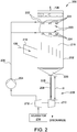
- FIG. 2 is a schematic view of AQCS 200.
- marine vessel 100 includes a power source 102, preferably located in a lower portion of marine vessel 100, such as at a lower deck or bilge (not shown) of marine vessel 100.
- Power source 102 is, for example, and without limitation, a marine diesel engine, gas turbine engine, steam turbine engine and boiler system, and/or any type of marine engine that enables marine vessel 100 to function as described herein.
- Marine vessel 100 includes an exhaust stack 104, which is part of a superstructure 101 of marine vessel 100, for receiving a process gas from power source 102, such as an exhaust gas flow 106.
- exhaust gas flow 106 contains various pollutants.
- Exhaust gas flow 106 enters a gas cleaning device, or scrubber section 202 of AQCS 200, wherein exhaust gas flow 106 is at least partially cleaned, i.e., exhaust gas flow 106 has at least a portion of pollutants removed from exhaust gas flow 106 by scrubber section 202.
- Exhaust gas flow 106 exits vessel 100 via exhaust stack 104 as at least a partially clean exhaust gas flow 108. While scrubber section 202 of AQCS 200 is shown located in stack 104, in alternative embodiments, scrubber section 202 may be located in other portions of superstructure 101 or otherwise above a main deck 103 of marine vessel 100.
- AQCS 200 includes at least one feed pump 204 for pumping a clean fluid flow 206, for example, and without limitation, seawater 214, to scrubber section 202 to facilitate cleaning exhaust gas flow 106.
- scrubber 202 is located at least partially in exhaust stack 104.
- scrubber 202 may be located entirely in exhaust stack 104 or may be located external to exhaust stack 104.
- clean fluid flow 206 flows downwardly through scrubber section 202 and absorbs at least a portion of the pollutants in exhaust gas flow 106 to produce partially clean exhaust gas flow 108 and an effluent fluid flow 208. Effluent fluid flow 208 is collected and channeled downwardly to an energy recovery device 210.
- a fluid column 209 of effluent fluid flow 208 has a predetermined fluid column height "H" defined above energy recovery device 210.
- effluent fluid flow 208 has an amount of potential energy due to height "H” of fluid column 209, and when flowing, effluent fluid flow 208 has an amount of kinetic energy that is recoverable by energy recovery device 210.
- energy recovery device 210 is a turbine, referred to herein as an energy recovery turbine, that is rotatably coupled to a pre-pump turbine 212 that channels, or propels clean fluid 206, such as seawater 214 to feed pump 204.
- Energy recovery turbine 210 and pre-pump turbine 212 facilitate reducing the power required to pump clean fluid flow 206 to scrubber section 202, and as such, facilitates an increase in the efficiency of marine vessel 100, and in particular power source 102.
- energy recovery turbine 210 is a water turbine or hydro-turbine that converts kinetic energy of a fluid, such as seawater 214, into mechanical work.
- energy recovery turbine 210 is a reaction turbine.
- a reaction turbine as the term is used herein, is a turbine acted on by a fluid that changes pressure as it flows through the turbine and transfers its energy to the turbine.
- energy recovery turbine 210 may be any type of hydro-turbine that enables AQCS 200 to function as described herein, such as, for example, and without limitation, an impulse turbine, such as a Pelton wheel turbine or a cross-flow turbine.
- energy recovery turbine 210 and scrubber section 202 are located a predetermined distance apart that defines height "H" of fluid column 209.
- scrubber section 202 is located above energy recovery turbine 210 such that height "H” is in the range of between about 15 meters (m) (49 feet (ft.)) to about 40 m ( 131 ft.).
- effluent fluid flow 208 has a hydrostatic pressure, or head pressure, in the range of between about 147 kilopascals (kPa) (23.1 pounds per square inch (psi)) to about 392 kPA (57 psi).
- energy recovery turbine 210 and scrubber section 202 may be located at any height "H" apart that enables AQCS 200 to function as described herein.
- exhaust gas flow 106 contains, for example, sulphur oxides, nitrogen oxides, hydrocarbons, heavy metals, carbon oxides, particulate matter, and various other pollutants.
- exhaust gas flow 106 flows to scrubber section 202 and enters interior 216 of scrubber section 202 via an inlet 218.
- Exhaust gas flow 106 flows upwards through scrubber section 202.
- scrubber section 202 is a spray tower, such that interior 216 of scrubber section 202 includes a plurality of fluid spray assemblies 220 arranged vertically above one another.
- scrubber section 202 inlcudes, for example, and without limitation, a packed bed scrubber, a FLOWPAC ® turbulent bed absorber, and/or any other wet flue gas scrubber that enables crubber section 202 to function as described herein.
- a packed bed scrubber for example, and without limitation, a FLOWPAC ® turbulent bed absorber, and/or any other wet flue gas scrubber that enables crubber section 202 to function as described herein.
- only two fluid spray assemblies 220 are shown.
- scrubber section 202 may include any number of fluid spray assemblies 220 that enables AQCS 200 to function as described herein.
- the number of fluid spray assemblies 220 in operation at any point in time can be less than the number of fluid spray assemblies 220 installed in scrubber section 202.
- Each fluid spray assembly 220 includes a fluid supply line 222 and a plurality of nozzles 224 coupled in fluid communication to a respective fluid supply line 222.
- Clean fluid flow 206 such as seawater 214, supplied via fluid supply lines 222 to nozzles 224 is atomized and contacts interior 216 of scrubber section 202 and exhaust gas flow 106 to facilitate absorption of the pollutants, for example, and without limitation, the sulphur oxides and nitrogen oxides.
- Feed pump 204 pumps clean fluid flow 206 to fluid supply lines 222.
- energy recovery turbine 210 rotates pre-pump turbine 212.
- Pre-pump turbine 212 channels seawater 214 a predetermined distance upwardly to feed pump 204 to facilitate reducing the power requirement for feed pump 204.
- feed pump 204 can be moved vertically closer to fluid supply lines 222 when receiving seawater 214 from pre-pump turbine 212.
- pre-pump turbine 212 increases the pressure of seawater 214 a predetermined amount, thereby facilitating reducing the head or pressure of feed pump 204.
- the atomized clean fluid flow 206 flows downwardly through interior 216 of scrubber section 202 of AQCS 200 and absorbs pollutants from exhaust gas flow 106 flowing upwardly.
- Effluent fluid flow 208 is collected in a lower portion 226 of scrubber section 202 of AQCS 200. At least a portion of effluent fluid flow 208 is channeled to energy recovery turbine 210 via a fluid conduit 228 to operate pre-pump turbine 212, and is then discharged to, for example, the environment. For example, and without limitation, effluent fluid flow 208 is directed towards blades (not shown) of energy recovery turbine 210, thus generating a force on the blades and causing energy recovery turbine 210 to rotate and generate mechanical work. Thus, effluent fluid flow 208, due to its hydrostatic pressure, or head, transfers energy from effluent fluid flow 208 to energy recovery turbine 210.
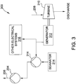
- FIG. 3 is an exemplary arrangement 300 of an alternative energy recovery turbine 310 that may be used with AQCS 200 (shown in FIG. 2 ).
- energy recovery turbine 310 is coupled to an electric generator 312 for converting the energy transferred from effluent fluid flow 208 to electrical power.
- electric generator 312 is an integral component of energy recovery turbine 310.
- electric generator 312 is coupled to an electric pump 314 and/or other electrical systems 316 of marine vessel 100.
- electric pump 314 channels, or propels clean fluid 206, such as seawater 214 to feed pump 204.
- Energy recovery turbine 310 and electric pump 314 facilitate reducing the power required to pump clean fluid flow 206 to scrubber section 202, thereby facilitating an increase in the efficiency of marine vessel 100, and in particular power source 102.
- energy recovery turbine 310 similarly is a hydro-turbine that converts kinetic energy of a fluid, such as seawater 214, into mechanical work.
- energy recovery turbine 310 is a reaction turbine.
- energy recovery turbine 310 is any type of hydro-turbine that enables AQCS 200 to function as described herein, for example, and without limitation, an impulse turbine, such as a Pelton wheel turbine or a cross-flow turbine.
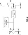
- FIG. 4 is an alternative exemplary arrangement 400 of energy recovery turbine 310 and electric generator 312 that may be used with AQCS 200 (shown in FIG. 2 ).
- energy recovery turbine 310 is coupled to electric generator 312 for converting the energy transferred from effluent fluid flow 208 to electrical power.
- Electric generator 312 is coupled to feed pump 204 and/or to other electrical systems 402 of marine vessel 100.
- Energy recovery turbine 310 and electric generator 312 facilitate reducing an amount of power required from power source 102 to pump clean fluid flow 206 to scrubber section 202, thereby facilitating an increase in the efficiency of marine vessel 100, and in particular power source 102.
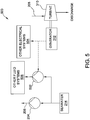
- FIG. 5 is an alternative exemplary arrangement 500 of energy recovery turbine 310 and electric generator 312 that may be used with AQCS 200 (shown in FIG. 1 ).
- energy recovery turbine 310 is coupled to electric generator 312 for converting the energy transferred from effluent fluid flow 208 to electrical power.
- Electric generator 312 is coupled to one or more of a fluid pump 502 and other electrical systems 504 of marine vessel 100.
- fluid pump 502 is coupled in flow communication to one or more other fluid systems 506 of marine vessel 100, for example, and without limitation, a cooling system (not shown) of power source 102 (shown in FIG. 1 ), a fire fighting system (not shown), and a desalination system (not shown).
- Energy recovery turbine 310 and electric generator 312 facilitate reducing an amount of power required from power source 102 to pump seawater 214 to other fluid systems 506 of marine vessel 100 and power other electrical systems 504 of marine vessel 100, thereby facilitating an increase in the efficiency of marine vessel 100, and in particular power source 102.
- an energy recovery device receives an effluent fluid flow having a predetermined water column height or pressure head to convert the kinetic energy of the fluid to mechanical work.
- the energy recovery device can rotate a pump to facilitate pumping a fluid, or rotate an electric generator to generate electrical power.
- the systems and methods described herein facilitate recovering energy that is typically lost, and as such, increases the efficiency of the marine vessel.
- the systems and methods described herein facilitate reducing the fuel consumed by the marine vessel engine, which may lead to decreased pollutant emissions.
- An exemplary technical effect of the methods and systems described herein includes at least one of: (a) channeling a fluid column to an energy recovery device; (b) converting potential and kinetic energy of the fluid column to mechanical work; (c) rotating a pump for pumping a fluid to a feed pump of a marine air quality control system (AQCS); and (d) generating electrical power to power electrical systems of the vessel.
- AQCS marine air quality control system
Landscapes
- Engineering & Computer Science (AREA)
- Chemical & Material Sciences (AREA)
- Combustion & Propulsion (AREA)
- General Chemical & Material Sciences (AREA)
- Oil, Petroleum & Natural Gas (AREA)
- Chemical Kinetics & Catalysis (AREA)
- Environmental & Geological Engineering (AREA)
- Analytical Chemistry (AREA)
- Health & Medical Sciences (AREA)
- Biomedical Technology (AREA)
- Mechanical Engineering (AREA)
- General Engineering & Computer Science (AREA)
- Ocean & Marine Engineering (AREA)
- Exhaust Gas After Treatment (AREA)
- Treating Waste Gases (AREA)
Abstract
Description
- The field of the present disclosure relates generally to air quality control systems, and more specifically, to systems and methods that facilitate energy recovery from air quality control systems for marine vessels.
- At least some known marine vessels use heavy oil as a fuel for the marine diesel engines. Such marine engines may emit significant amounts of pollution or pollutants that contribute to environmental and public health problems. The emitted pollution may include oxides of sulfur, oxides of nitrogen, hydrocarbons, heavy metals, carbon monoxide, carbon dioxide, particulate matter, and/or various other pollutants, all of which may be harmful to the environment and to humans.
- As such, marine vessels must meet increasingly stringent emissions requirements. For example, the emissions requirements have decreased the allowable levels of pollutant emissions from marine engines. Moreover, at least some known marine vessels include a marine air quality control system (AQCS) that uses a seawater scrubber used to facilitate cleaning the engine exhaust. In at least some known AQCS's, seawater is pumped through an absorber located in the top of the marine vessel (i.e., in the stack). The pumping height may be approximately 20 meters (m) to approximately 30 m above the sea surface, and as such, requires large feed pumps that consume increased amounts of energy to operate. As a result, such systems reduce the efficiency of the marine vessel as the marine engine must supply increased energy for the large feed pumps. In addition, the reduced efficiency may increase the fuel consumed by the marine engine, which may lead to increased pollutant emissions.
- In one aspect, an air quality control system for use in cleaning a process gas is provided. The air quality control system includes a gas cleaning device positioned to receive a process gas containing pollutants and a clean fluid flow. The gas cleaning device causes the clean fluid flow to contact the process gas to at least partially remove the pollutants from the process gas, thereby generating an at least partially clean exhaust gas flow and an effluent fluid flow. The air quality control system also includes a fluid conduit positioned to receive the effluent fluid flow from the gas cleaning device. The fluid conduit defines a fluid column of effluent fluid flow that has an amount of kinetic energy based on a height of the fluid column. Moreover, the air quality control system includes an energy recovery device positioned to receive the effluent fluid flow from the fluid conduit and convert a portion of the amount of kinetic energy of the effluent fluid flow to mechanical work.
- In another aspect, a method for recovering energy from an air quality control system is provided. The method includes channeling a clean fluid flow to an interior of a gas cleaning device. The method also includes contacting a process gas flowing through the interior of the gas cleaning device with the clean fluid flow to generate an effluent fluid flow. Moreover, the method includes channeling the effluent fluid flow to an energy recovery device via a fluid conduit. The fluid conduit defines a fluid column of the effluent fluid flow that has an amount of kinetic energy based on a height of the fluid column. The method also includes converting, using the energy recovery device, a portion of the amount of kinetic energy of the effluent fluid flow to mechanical work.
- These and other features, aspects, and advantages of the present disclosure will become better understood when the following detailed description is read with reference to the accompanying drawings in which like characters represent like parts throughout the drawings, wherein:
-
FIG. 1 is a plan view of a marine vessel including an exemplary marine open-loop air quality control system (AQCS); -
FIG. 2 is a schematic view of the AQCS shown inFIG. 1 ; -
FIG. 3 is an exemplary arrangement of an alternative energy recovery turbine that may be used with the AQCS shown inFIG. 2 ; -
FIG. 4 is an alternative arrangement of the energy recovery turbine and an electric generator shown inFIG. 3 that may be used with the AQCS shown inFIG. 2 ; and -
FIG. 5 is another alternative arrangement of the energy recovery turbine and the electric generator shown inFIG. 3 that may be used with the AQCS shown inFIG. 2 . - Unless otherwise indicated, the drawings provided herein are meant to illustrate features of embodiments of the disclosure. These features are believed to be applicable in a wide variety of systems comprising one or more embodiments of the disclosure. As such, the drawings are not meant to include all conventional features known by those of ordinary skill in the art to be required for the practice of the embodiments disclosed herein.
- In the following specification and the claims, reference will be made to a number of terms, which shall be defined to have the following meanings. The singular forms "a," "an," and "the" include plural references unless the context clearly dictates otherwise. "Optional" or "optionally" means that the subsequently described event or circumstance may or may not occur, and that the description includes instances where the event occurs and instances where it does not. Furthermore, references to "one embodiment" are not intended to be interpreted as excluding the existence of additional embodiments that also incorporate the recited features. Moreover, unless explicitly stated to the contrary, embodiments "including" or "having" an element or a plurality of elements having a particular property may include additional such elements not having that property.
- Approximating language, as used herein throughout the specification and claims, may be applied to modify any quantitative representation that could permissibly vary without resulting in a change in the basic function to which it is related. Accordingly, a value modified by a term or terms such as "about," "approximately," and "substantially" are not to be limited to the precise value specified. In at least some instances, the approximating language may correspond to the precision of an instrument for measuring the value. Here and throughout the specification and claims, range limitations may be combined and/or interchanged; such ranges are identified and include all the sub-ranges contained therein unless context or language indicates otherwise.
-
FIG. 1 is a plan view of an exemplarymarine vessel 100 including an exemplary marine open-loop air quality control system (AQCS) 200.FIG. 2 is a schematic view ofAQCS 200. In the exemplary embodiment,marine vessel 100 includes apower source 102, preferably located in a lower portion ofmarine vessel 100, such as at a lower deck or bilge (not shown) ofmarine vessel 100.Power source 102 is, for example, and without limitation, a marine diesel engine, gas turbine engine, steam turbine engine and boiler system, and/or any type of marine engine that enablesmarine vessel 100 to function as described herein.Marine vessel 100 includes anexhaust stack 104, which is part of asuperstructure 101 ofmarine vessel 100, for receiving a process gas frompower source 102, such as anexhaust gas flow 106. In the exemplary embodiment,exhaust gas flow 106 contains various pollutants.Exhaust gas flow 106 enters a gas cleaning device, orscrubber section 202 ofAQCS 200, whereinexhaust gas flow 106 is at least partially cleaned, i.e.,exhaust gas flow 106 has at least a portion of pollutants removed fromexhaust gas flow 106 byscrubber section 202.Exhaust gas flow 106 exitsvessel 100 viaexhaust stack 104 as at least a partially cleanexhaust gas flow 108. Whilescrubber section 202 ofAQCS 200 is shown located instack 104, in alternative embodiments,scrubber section 202 may be located in other portions ofsuperstructure 101 or otherwise above amain deck 103 ofmarine vessel 100. - In the exemplary embodiment,
AQCS 200 includes at least onefeed pump 204 for pumping aclean fluid flow 206, for example, and without limitation,seawater 214, toscrubber section 202 to facilitate cleaningexhaust gas flow 106. In the exemplary embodiment,scrubber 202 is located at least partially inexhaust stack 104. Alternatively,scrubber 202 may be located entirely inexhaust stack 104 or may be located external toexhaust stack 104. In the exemplary embodiment,clean fluid flow 206 flows downwardly throughscrubber section 202 and absorbs at least a portion of the pollutants inexhaust gas flow 106 to produce partially cleanexhaust gas flow 108 and aneffluent fluid flow 208.Effluent fluid flow 208 is collected and channeled downwardly to anenergy recovery device 210. In the exemplary embodiment, afluid column 209 ofeffluent fluid flow 208 has a predetermined fluid column height "H" defined aboveenergy recovery device 210. Thus,effluent fluid flow 208 has an amount of potential energy due to height "H" offluid column 209, and when flowing,effluent fluid flow 208 has an amount of kinetic energy that is recoverable byenergy recovery device 210. In the exemplary embodiment,energy recovery device 210 is a turbine, referred to herein as an energy recovery turbine, that is rotatably coupled to apre-pump turbine 212 that channels, or propelsclean fluid 206, such asseawater 214 to feedpump 204.Energy recovery turbine 210 andpre-pump turbine 212 facilitate reducing the power required to pumpclean fluid flow 206 toscrubber section 202, and as such, facilitates an increase in the efficiency ofmarine vessel 100, and inparticular power source 102. - In the exemplary embodiments, as described herein,
energy recovery turbine 210 is a water turbine or hydro-turbine that converts kinetic energy of a fluid, such asseawater 214, into mechanical work. In the exemplary embodiment,energy recovery turbine 210 is a reaction turbine. A reaction turbine, as the term is used herein, is a turbine acted on by a fluid that changes pressure as it flows through the turbine and transfers its energy to the turbine. In alternative embodiments,energy recovery turbine 210 may be any type of hydro-turbine that enablesAQCS 200 to function as described herein, such as, for example, and without limitation, an impulse turbine, such as a Pelton wheel turbine or a cross-flow turbine. - In the exemplary embodiment,
energy recovery turbine 210 andscrubber section 202 are located a predetermined distance apart that defines height "H" offluid column 209. For example, and without limitation, in one embodiment,scrubber section 202 is located aboveenergy recovery turbine 210 such that height "H" is in the range of between about 15 meters (m) (49 feet (ft.)) to about 40 m ( 131 ft.). Thus,effluent fluid flow 208 has a hydrostatic pressure, or head pressure, in the range of between about 147 kilopascals (kPa) (23.1 pounds per square inch (psi)) to about 392 kPA (57 psi). Alternatively,energy recovery turbine 210 andscrubber section 202 may be located at any height "H" apart that enablesAQCS 200 to function as described herein. - In the exemplary embodiment,
exhaust gas flow 106 contains, for example, sulphur oxides, nitrogen oxides, hydrocarbons, heavy metals, carbon oxides, particulate matter, and various other pollutants. In operation, with reference toFIG. 2 ,exhaust gas flow 106 flows toscrubber section 202 and enters interior 216 ofscrubber section 202 via aninlet 218.Exhaust gas flow 106 flows upwards throughscrubber section 202. In the exemplary embodiment,scrubber section 202 is a spray tower, such thatinterior 216 ofscrubber section 202 includes a plurality offluid spray assemblies 220 arranged vertically above one another. In alternative embodiments,scrubber section 202 inlcudes, for example, and without limitation, a packed bed scrubber, a FLOWPAC® turbulent bed absorber, and/or any other wet flue gas scrubber that enablescrubber section 202 to function as described herein. In the exemplary embodiment, only twofluid spray assemblies 220 are shown. Alternatively,scrubber section 202 may include any number offluid spray assemblies 220 that enablesAQCS 200 to function as described herein. - In some embodiments, the number of
fluid spray assemblies 220 in operation at any point in time can be less than the number offluid spray assemblies 220 installed inscrubber section 202. Eachfluid spray assembly 220 includes afluid supply line 222 and a plurality ofnozzles 224 coupled in fluid communication to a respectivefluid supply line 222.Clean fluid flow 206, such asseawater 214, supplied viafluid supply lines 222 tonozzles 224 is atomized and contacts interior 216 ofscrubber section 202 andexhaust gas flow 106 to facilitate absorption of the pollutants, for example, and without limitation, the sulphur oxides and nitrogen oxides. -
Feed pump 204 pumpsclean fluid flow 206 tofluid supply lines 222. However, to facilitate reducing the power used byfeed pump 204 to pumpclean fluid flow 206 tofluid supply lines 222,energy recovery turbine 210 rotatespre-pump turbine 212.Pre-pump turbine 212 channels seawater 214 a predetermined distance upwardly to feedpump 204 to facilitate reducing the power requirement forfeed pump 204. For example, and without limitation, feedpump 204 can be moved vertically closer tofluid supply lines 222 when receivingseawater 214 frompre-pump turbine 212. Alternatively,pre-pump turbine 212 increases the pressure of seawater 214 a predetermined amount, thereby facilitating reducing the head or pressure offeed pump 204. In the exemplary embodiment, the atomizedclean fluid flow 206 flows downwardly throughinterior 216 ofscrubber section 202 ofAQCS 200 and absorbs pollutants fromexhaust gas flow 106 flowing upwardly. -
Effluent fluid flow 208 is collected in alower portion 226 ofscrubber section 202 ofAQCS 200. At least a portion ofeffluent fluid flow 208 is channeled toenergy recovery turbine 210 via afluid conduit 228 to operatepre-pump turbine 212, and is then discharged to, for example, the environment. For example, and without limitation,effluent fluid flow 208 is directed towards blades (not shown) ofenergy recovery turbine 210, thus generating a force on the blades and causingenergy recovery turbine 210 to rotate and generate mechanical work. Thus,effluent fluid flow 208, due to its hydrostatic pressure, or head, transfers energy fromeffluent fluid flow 208 toenergy recovery turbine 210. -
FIG. 3 is anexemplary arrangement 300 of an alternativeenergy recovery turbine 310 that may be used with AQCS 200 (shown inFIG. 2 ). In the exemplary embodiment,energy recovery turbine 310 is coupled to anelectric generator 312 for converting the energy transferred fromeffluent fluid flow 208 to electrical power. In some embodiments,electric generator 312 is an integral component ofenergy recovery turbine 310. In the exemplary embodiment,electric generator 312 is coupled to anelectric pump 314 and/or otherelectrical systems 316 ofmarine vessel 100. In the exemplary embodiment,electric pump 314 channels, or propelsclean fluid 206, such asseawater 214 to feedpump 204.Energy recovery turbine 310 andelectric pump 314 facilitate reducing the power required to pumpclean fluid flow 206 toscrubber section 202, thereby facilitating an increase in the efficiency ofmarine vessel 100, and inparticular power source 102. As described herein with respect toenergy recovery turbine 210,energy recovery turbine 310 similarly is a hydro-turbine that converts kinetic energy of a fluid, such asseawater 214, into mechanical work. In the exemplary embodiment,energy recovery turbine 310 is a reaction turbine. In alternative embodiments,energy recovery turbine 310 is any type of hydro-turbine that enablesAQCS 200 to function as described herein, for example, and without limitation, an impulse turbine, such as a Pelton wheel turbine or a cross-flow turbine. -
FIG. 4 is an alternativeexemplary arrangement 400 ofenergy recovery turbine 310 andelectric generator 312 that may be used with AQCS 200 (shown inFIG. 2 ). In the exemplary embodiment,energy recovery turbine 310 is coupled toelectric generator 312 for converting the energy transferred fromeffluent fluid flow 208 to electrical power.Electric generator 312 is coupled to feedpump 204 and/or to otherelectrical systems 402 ofmarine vessel 100.Energy recovery turbine 310 andelectric generator 312 facilitate reducing an amount of power required frompower source 102 to pumpclean fluid flow 206 toscrubber section 202, thereby facilitating an increase in the efficiency ofmarine vessel 100, and inparticular power source 102. -
FIG. 5 is an alternativeexemplary arrangement 500 ofenergy recovery turbine 310 andelectric generator 312 that may be used with AQCS 200 (shown inFIG. 1 ). In the exemplary embodiment,energy recovery turbine 310 is coupled toelectric generator 312 for converting the energy transferred fromeffluent fluid flow 208 to electrical power.Electric generator 312 is coupled to one or more of afluid pump 502 and otherelectrical systems 504 ofmarine vessel 100. In some embodiments,fluid pump 502 is coupled in flow communication to one or more otherfluid systems 506 ofmarine vessel 100, for example, and without limitation, a cooling system (not shown) of power source 102 (shown inFIG. 1 ), a fire fighting system (not shown), and a desalination system (not shown).Energy recovery turbine 310 andelectric generator 312 facilitate reducing an amount of power required frompower source 102 to pumpseawater 214 to otherfluid systems 506 ofmarine vessel 100 and power otherelectrical systems 504 ofmarine vessel 100, thereby facilitating an increase in the efficiency ofmarine vessel 100, and inparticular power source 102. - The systems and methods described herein facilitate recovering energy from an effluent fluid flow discharged by a scrubber used for cleaning an exhaust gas flow. Specifically, in the exemplary embodiments, an energy recovery device receives an effluent fluid flow having a predetermined water column height or pressure head to convert the kinetic energy of the fluid to mechanical work. The energy recovery device can rotate a pump to facilitate pumping a fluid, or rotate an electric generator to generate electrical power. As such, in contrast to known marine vessels, the systems and methods described herein facilitate recovering energy that is typically lost, and as such, increases the efficiency of the marine vessel. In addition, the systems and methods described herein facilitate reducing the fuel consumed by the marine vessel engine, which may lead to decreased pollutant emissions.
- An exemplary technical effect of the methods and systems described herein includes at least one of: (a) channeling a fluid column to an energy recovery device; (b) converting potential and kinetic energy of the fluid column to mechanical work; (c) rotating a pump for pumping a fluid to a feed pump of a marine air quality control system (AQCS); and (d) generating electrical power to power electrical systems of the vessel.
- The methods and systems described herein are not limited to the specific embodiments described herein. For example, components of each system and/or steps of each method may be utilized independently and separately from other components and/or steps described herein. For example, the method and systems may also be used in combination with other energy recovery systems, and are not limited to practice only with the marine air quality control systems as described herein. Rather, the exemplary embodiment can be implemented and utilized in connection with many other energy recovery systems.
- Although specific features of various embodiments of the disclosure may be shown in some drawings and not in others, this is for convenience only. In accordance with the principles of the disclosure, any feature of a drawing may be referenced and/or claimed in combination with any feature of any other drawing.
- This written description uses examples to disclose the systems and methods described herein, including the best mode, and also to enable any person skilled in the art to practice the disclosure, including making and using any devices or systems and performing any incorporated methods. The patentable scope of the disclosure is defined by the claims, and may include other examples that occur to those skilled in the art. Such other examples are intended to be within the scope of the claims if they have structural elements that do not differ from the literal language of the claims, or if they include equivalent structural elements with insubstantial differences from the literal language of the claims.
-
- 1. An air quality control system for use in cleaning a process gas, said system comprising:
- a gas cleaning device positioned to receive a process gas containing pollutants and a clean fluid flow, said gas cleaning device causes the clean fluid flow to contact the process gas to at least partially remove the pollutants from the process gas, thereby generating an at least partially clean exhaust gas flow and an effluent fluid flow;
- a fluid conduit positioned to receive the effluent fluid flow discharged from said gas cleaning device, said fluid conduit defining a fluid column of effluent fluid flow having an amount of kinetic energy based on a height of the fluid column; and
- an energy recovery device positioned to:
- receive the effluent fluid flow from said fluid conduit; and
- convert a portion of the amount of kinetic energy of the effluent fluid flow to mechanical work.
- 2. An air quality control system in accordance with clause 1 further comprising a pre-pump turbine rotatably coupled to said energy recovery device and rotatable by the mechanical work.
- 3. An air quality control system in accordance with clause 2 further comprising a feed pump configured to channel the clean fluid flow to said gas cleaning device, wherein said pre-pump turbine is coupled in flow communication to said feed pump and configured to channel fluid to said feed pump to generate the clean fluid flow.
- 4. An air quality control system in accordance with clause 1 further comprising an electric generator configured to convert the mechanical work into electrical power.
- 5. An air quality control system in accordance with clause 4 further comprising a pump coupled to said electric generator.
- 6. An air quality control system in accordance with clause 5 further comprising a feed pump configured to channel the clean fluid flow to said gas cleaning device, wherein said pump is coupled in flow communication to said feed pump and configured to channel fluid to said feed pump to generate the clean fluid flow.
- 7. An air quality control system in accordance with clause 5, wherein said pump is configured to channel the clean fluid flow to said gas cleaning device.
- 8. An air quality control system in accordance with clause 1, wherein said energy recovery device is a hydro-turbine configured to convert kinetic energy of the effluent fluid flow into mechanical work.
- 9. An air quality control system in accordance with clause 1, wherein said air quality control system is disposed in a marine vessel, said gas cleaning device is positioned above a main deck of said marine vessel, and said energy recovery device is positioned below said main deck.
- 10. An air quality control system in accordance with clause 11, wherein said gas cleaning device is positioned in an exhaust stack of said marine vessel
- 11. A method for recovering energy from an air quality control system, said method comprising:
- channeling a clean fluid flow to an interior of a gas cleaning device;
- contacting a process gas flowing through the interior of the gas cleaning device with the clean fluid flow to generate an effluent fluid flow;
- channeling the effluent fluid flow to an energy recovery device via a fluid conduit, the fluid conduit defining a fluid column of the effluent fluid flow having an amount of kinetic energy based on a height of the fluid column; and
- converting, using the energy recovery device, a portion of the amount of kinetic energy of the effluent fluid flow to mechanical work.
- 12. A method in accordance with clause 11 further comprising rotating a pre-pump turbine rotatably coupled to the energy recovery device using the mechanical work.
- 13. A method in accordance with clause 12 further comprising channeling the clean fluid flow to the gas cleaning device using a feed pump, wherein the pre-pump turbine is coupled in flow communication to the feed pump and configured to channel fluid to the feed pump to generate the clean fluid flow.
- 14. A method in accordance with clause 11 further comprising converting a portion of the mechanical work to electrical power using an electric generator.
- 15. A method in accordance with clause 14 further comprising operating an electric pump coupled to said electric generator to pump a fluid.
- 16. A method in accordance with clause 15 further comprising:
- channeling the clean fluid flow to the gas cleaning device using a feed pump; and
- channeling the fluid pumped by the electric pump to the feed pump to generate the clean fluid flow.
- 17. A method in accordance with clause 15, wherein operating the electric pump comprises operating the electric pump to channel the clean fluid flow to the gas cleaning device.
- 18. A method in accordance with clause 11, wherein channeling the effluent fluid flow to the energy recovery device comprises channeling the effluent fluid flow to a hydro-turbine configured to convert the portion of the amount of kinetic energy kinetic energy of the effluent fluid flow into mechanical work.
- 19. A method in accordance with clause 11 further comprising:
- positioning the gas cleaning device above a main deck of a marine vessel; and
- positioning the energy recovery device below the main deck, wherein the air quality control system is disposed in the marine vessel.
- 20. A method in accordance with clause 19, wherein positioning the gas cleaning device above a main deck of a marine vessel comprises positioning the gas cleaning device in an exhaust stack of the marine vessel.
Claims (10)
- An air quality control system (200) for use in cleaning a process gas (106), said system comprising:a gas cleaning device (202) positioned to receive a process gas (106) containing pollutants and a clean fluid flow (206), said gas cleaning device (202) causes the clean fluid flow (206) to contact the process gas (106) to at least partially remove the pollutants from the process gas (106), thereby generating an at least partially clean exhaust gas flow (108) and an effluent fluid flow (208);a fluid conduit (228) positioned to receive the effluent fluid flow (208) discharged from said gas cleaning device (202), said fluid conduit (228) defining a fluid column (209) of effluent fluid flow (208) having an amount of kinetic energy based on a height (H) of the fluid column (209); andan energy recovery device (210) positioned to:receive the effluent fluid flow (208) from said fluid conduit (228); andconvert a portion of the amount of kinetic energy of the effluent fluid flow (208) to mechanical work.
- An air quality control system (200) in accordance with Claim 1 further comprising a pre-pump turbine (212) rotatably coupled to said energy recovery device (210) and rotatable by the mechanical work.
- An air quality control system (200) in accordance with Claim 1 or 2 further comprising a feed pump (204) configured to channel the clean fluid flow (206) to said gas cleaning device (202), wherein said pre-pump turbine (212) is coupled in flow communication to said feed pump (204) and configured to channel fluid to said feed pump (204) to generate the clean fluid flow (206).
- An air quality control system (200) in accordance with any preceding claim further comprising an electric generator (312) configured to convert the mechanical work into electrical power.
- An air quality control system (200) in accordance with any preceding claim, wherein said air quality control system (200) is disposed in a marine vessel (100), said gas cleaning device (202) is positioned above a main deck (103) of said marine vessel (100), and said energy recovery device (210) is positioned below said main deck (103).
- A method for recovering energy from an air quality control system (200), said method comprising:channeling a clean fluid flow (206) to an interior of a gas cleaning device (202);contacting a process gas (106) flowing through the interior (216) of the gas cleaning device (202) with the clean fluid flow (206) to generate an effluent fluid flow (208);channeling the effluent fluid flow (208) to an energy recovery device (210) via a fluid conduit (228), the fluid conduit (228) defining a fluid column (209) of the effluent fluid flow (208) having an amount of kinetic energy based on a height (H) of the fluid column (209); andconverting, using the energy recovery device (210), a portion of the amount of kinetic energy of the effluent fluid flow (208) to mechanical work.
- A method in accordance with Claim 6 further comprising rotating a pre-pump turbine (212) rotatably coupled to the energy recovery device (210) using the mechanical work.
- A method in accordance with Claim 6 or 7 further comprising converting a portion of the mechanical work to electrical power using an electric generator (312).
- A method in accordance with any one of Claims 6 to 8, wherein channeling the effluent fluid flow (208) to the energy recovery device (210) comprises channeling the effluent fluid flow (208) to a hydro-turbine configured to convert the portion of the amount of kinetic energy kinetic energy of the effluent fluid flow (208) into mechanical work.
- A method in accordance with any one of Claims 6 to 9 further comprising:positioning the gas cleaning device (202) above a main deck (103) of a marine vessel (100); andpositioning the energy recovery device (210) below the main deck (103), wherein the air quality control system (200) is disposed in the marine vessel (100).
Priority Applications (2)
| Application Number | Priority Date | Filing Date | Title |
|---|---|---|---|
| EP16197264.1A EP3318315B1 (en) | 2016-11-04 | 2016-11-04 | Method and systems for energy recovery for marine exhaust gas control systems |
| PCT/EP2017/077678 WO2018083044A1 (en) | 2016-11-04 | 2017-10-27 | Method and systems for energy recovery for marine air quality control systems |
Applications Claiming Priority (1)
| Application Number | Priority Date | Filing Date | Title |
|---|---|---|---|
| EP16197264.1A EP3318315B1 (en) | 2016-11-04 | 2016-11-04 | Method and systems for energy recovery for marine exhaust gas control systems |
Publications (2)
| Publication Number | Publication Date |
|---|---|
| EP3318315A1 true EP3318315A1 (en) | 2018-05-09 |
| EP3318315B1 EP3318315B1 (en) | 2020-10-14 |
Family
ID=57256103
Family Applications (1)
| Application Number | Title | Priority Date | Filing Date |
|---|---|---|---|
| EP16197264.1A Active EP3318315B1 (en) | 2016-11-04 | 2016-11-04 | Method and systems for energy recovery for marine exhaust gas control systems |
Country Status (2)
| Country | Link |
|---|---|
| EP (1) | EP3318315B1 (en) |
| WO (1) | WO2018083044A1 (en) |
Cited By (1)
| Publication number | Priority date | Publication date | Assignee | Title |
|---|---|---|---|---|
| CN110605022A (en) * | 2019-09-26 | 2019-12-24 | 山东大学 | Ship engine exhaust reheat desulfurization and denitrification system and desulfurization and denitrification method |
Citations (6)
| Publication number | Priority date | Publication date | Assignee | Title |
|---|---|---|---|---|
| DE1006111B (en) * | 1953-01-24 | 1957-04-11 | Maerkische Steinkohlengewerksc | Process for drying and desulphurization of gas under increased pressure |
| US20100206171A1 (en) * | 2008-06-13 | 2010-08-19 | Sigan Peng | Ship flue gas desulphurization method and equipment |
| US20120260800A1 (en) * | 2009-12-15 | 2012-10-18 | Wartsila Finland Oy | Scrubber unit arrangement |
| US20130019530A1 (en) * | 2010-03-29 | 2013-01-24 | Sime Srl | Method and an apparatus for sweetening and dehydrating a hydrocarbon gas, in particular a natural gas |
| US20150118131A1 (en) * | 2013-10-28 | 2015-04-30 | Energy Recovery Inc. | Systems and methods for utilizing turbine systems within gas processing systems |
| EP3012010A1 (en) * | 2014-10-20 | 2016-04-27 | Lab Sa | Method and plant for purifying the exhaust gases of an engine of a marine vessel |
-
2016
- 2016-11-04 EP EP16197264.1A patent/EP3318315B1/en active Active
-
2017
- 2017-10-27 WO PCT/EP2017/077678 patent/WO2018083044A1/en not_active Ceased
Patent Citations (6)
| Publication number | Priority date | Publication date | Assignee | Title |
|---|---|---|---|---|
| DE1006111B (en) * | 1953-01-24 | 1957-04-11 | Maerkische Steinkohlengewerksc | Process for drying and desulphurization of gas under increased pressure |
| US20100206171A1 (en) * | 2008-06-13 | 2010-08-19 | Sigan Peng | Ship flue gas desulphurization method and equipment |
| US20120260800A1 (en) * | 2009-12-15 | 2012-10-18 | Wartsila Finland Oy | Scrubber unit arrangement |
| US20130019530A1 (en) * | 2010-03-29 | 2013-01-24 | Sime Srl | Method and an apparatus for sweetening and dehydrating a hydrocarbon gas, in particular a natural gas |
| US20150118131A1 (en) * | 2013-10-28 | 2015-04-30 | Energy Recovery Inc. | Systems and methods for utilizing turbine systems within gas processing systems |
| EP3012010A1 (en) * | 2014-10-20 | 2016-04-27 | Lab Sa | Method and plant for purifying the exhaust gases of an engine of a marine vessel |
Cited By (1)
| Publication number | Priority date | Publication date | Assignee | Title |
|---|---|---|---|---|
| CN110605022A (en) * | 2019-09-26 | 2019-12-24 | 山东大学 | Ship engine exhaust reheat desulfurization and denitrification system and desulfurization and denitrification method |
Also Published As
| Publication number | Publication date |
|---|---|
| EP3318315B1 (en) | 2020-10-14 |
| WO2018083044A1 (en) | 2018-05-11 |
Similar Documents
| Publication | Publication Date | Title |
|---|---|---|
| JP7656155B2 (en) | Marine carbon capture and storage methods and equipment | |
| US20210362094A1 (en) | Wind-Powered Direct Air Carbon Dioxide Capture for Ocean Sequestration | |
| EP2512627B1 (en) | Scrubber unit arrangement | |
| EP0744987B1 (en) | A method for removing and preventing emissions into the atmosphere of carbon dioxide (co 2) from exhaust gases from heat engines | |
| JP5773687B2 (en) | Seawater flue gas desulfurization system and power generation system | |
| JP2012179521A5 (en) | ||
| KR20110138464A (en) | Hydropower System for Ships and Ships with the Same | |
| JP2013154329A (en) | Seawater exhaust gas desulfurization system, and power generator system | |
| MX2014010111A (en) | Method and system for separating and destroying sour and acid gas. | |
| KR20180038420A (en) | Multi-level gas scrubber with multiple flooded scrubber heads | |
| KR20100000240A (en) | Energy saving ship | |
| EP3318315B1 (en) | Method and systems for energy recovery for marine exhaust gas control systems | |
| JP2013154330A (en) | Oxidation tank, seawater exhaust gas desulfurization system, and power generator system | |
| CN101387258A (en) | Water wheel generating set | |
| CN104689699A (en) | Exhaust gas scrubbing system of ship power device | |
| EP3501623A1 (en) | Compact scrubber and a method thereof | |
| KR20130107150A (en) | Exhaust gas discharging system and method for ship | |
| CN204320010U (en) | An integrated device for flue gas desulfurization and dust removal suitable for ships | |
| KR20230016692A (en) | Cyclone type exhaust gas purifier | |
| KR20120077966A (en) | Exhaust gas cleaning system for vessels | |
| Castroa et al. | CO2 capture from flue gases: a possibility to reduce the CO2 footprint in offshore oil installations | |
| KR20140009720A (en) | Dual mode waste heat recovery appratus for ship | |
| CN120529958A (en) | Net-zero carbon fossil energy production methods, CCS systems, and blue carbon power plants | |
| CN104162362A (en) | Device for absorbing and purifying SO2 in diesel engine tail gas by utilizing seawater | |
| CN115038507A (en) | Exhaust gas purification device |
Legal Events
| Date | Code | Title | Description |
|---|---|---|---|
| PUAI | Public reference made under article 153(3) epc to a published international application that has entered the european phase |
Free format text: ORIGINAL CODE: 0009012 |
|
| STAA | Information on the status of an ep patent application or granted ep patent |
Free format text: STATUS: THE APPLICATION HAS BEEN PUBLISHED |
|
| AK | Designated contracting states |
Kind code of ref document: A1 Designated state(s): AL AT BE BG CH CY CZ DE DK EE ES FI FR GB GR HR HU IE IS IT LI LT LU LV MC MK MT NL NO PL PT RO RS SE SI SK SM TR |
|
| AX | Request for extension of the european patent |
Extension state: BA ME |
|
| STAA | Information on the status of an ep patent application or granted ep patent |
Free format text: STATUS: REQUEST FOR EXAMINATION WAS MADE |
|
| 17P | Request for examination filed |
Effective date: 20181129 |
|
| RBV | Designated contracting states (corrected) |
Designated state(s): AL AT BE BG CH CY CZ DE DK EE ES FI FR GB GR HR HU IE IS IT LI LT LU LV MC MK MT NL NO PL PT RO RS SE SI SK SM TR |
|
| STAA | Information on the status of an ep patent application or granted ep patent |
Free format text: STATUS: EXAMINATION IS IN PROGRESS |
|
| 17Q | First examination report despatched |
Effective date: 20190607 |
|
| GRAP | Despatch of communication of intention to grant a patent |
Free format text: ORIGINAL CODE: EPIDOSNIGR1 |
|
| STAA | Information on the status of an ep patent application or granted ep patent |
Free format text: STATUS: GRANT OF PATENT IS INTENDED |
|
| INTG | Intention to grant announced |
Effective date: 20200512 |
|
| GRAS | Grant fee paid |
Free format text: ORIGINAL CODE: EPIDOSNIGR3 |
|
| GRAA | (expected) grant |
Free format text: ORIGINAL CODE: 0009210 |
|
| STAA | Information on the status of an ep patent application or granted ep patent |
Free format text: STATUS: THE PATENT HAS BEEN GRANTED |
|
| AK | Designated contracting states |
Kind code of ref document: B1 Designated state(s): AL AT BE BG CH CY CZ DE DK EE ES FI FR GB GR HR HU IE IS IT LI LT LU LV MC MK MT NL NO PL PT RO RS SE SI SK SM TR |
|
| REG | Reference to a national code |
Ref country code: GB Ref legal event code: FG4D |
|
| REG | Reference to a national code |
Ref country code: AT Ref legal event code: REF Ref document number: 1323039 Country of ref document: AT Kind code of ref document: T Effective date: 20201015 Ref country code: CH Ref legal event code: EP |
|
| REG | Reference to a national code |
Ref country code: DE Ref legal event code: R096 Ref document number: 602016045732 Country of ref document: DE |
|
| REG | Reference to a national code |
Ref country code: IE Ref legal event code: FG4D |
|
| REG | Reference to a national code |
Ref country code: AT Ref legal event code: MK05 Ref document number: 1323039 Country of ref document: AT Kind code of ref document: T Effective date: 20201014 |
|
| REG | Reference to a national code |
Ref country code: NL Ref legal event code: MP Effective date: 20201014 |
|
| PG25 | Lapsed in a contracting state [announced via postgrant information from national office to epo] |
Ref country code: GR Free format text: LAPSE BECAUSE OF FAILURE TO SUBMIT A TRANSLATION OF THE DESCRIPTION OR TO PAY THE FEE WITHIN THE PRESCRIBED TIME-LIMIT Effective date: 20210115 Ref country code: FI Free format text: LAPSE BECAUSE OF FAILURE TO SUBMIT A TRANSLATION OF THE DESCRIPTION OR TO PAY THE FEE WITHIN THE PRESCRIBED TIME-LIMIT Effective date: 20201014 Ref country code: PT Free format text: LAPSE BECAUSE OF FAILURE TO SUBMIT A TRANSLATION OF THE DESCRIPTION OR TO PAY THE FEE WITHIN THE PRESCRIBED TIME-LIMIT Effective date: 20210215 Ref country code: RS Free format text: LAPSE BECAUSE OF FAILURE TO SUBMIT A TRANSLATION OF THE DESCRIPTION OR TO PAY THE FEE WITHIN THE PRESCRIBED TIME-LIMIT Effective date: 20201014 Ref country code: NO Free format text: LAPSE BECAUSE OF FAILURE TO SUBMIT A TRANSLATION OF THE DESCRIPTION OR TO PAY THE FEE WITHIN THE PRESCRIBED TIME-LIMIT Effective date: 20210114 |
|
| REG | Reference to a national code |
Ref country code: LT Ref legal event code: MG4D |
|
| RAP4 | Party data changed (patent owner data changed or rights of a patent transferred) |
Owner name: GENERAL ELECTRIC TECHNOLOGY GMBH |
|
| PG25 | Lapsed in a contracting state [announced via postgrant information from national office to epo] |
Ref country code: BG Free format text: LAPSE BECAUSE OF FAILURE TO SUBMIT A TRANSLATION OF THE DESCRIPTION OR TO PAY THE FEE WITHIN THE PRESCRIBED TIME-LIMIT Effective date: 20210114 Ref country code: LV Free format text: LAPSE BECAUSE OF FAILURE TO SUBMIT A TRANSLATION OF THE DESCRIPTION OR TO PAY THE FEE WITHIN THE PRESCRIBED TIME-LIMIT Effective date: 20201014 Ref country code: PL Free format text: LAPSE BECAUSE OF FAILURE TO SUBMIT A TRANSLATION OF THE DESCRIPTION OR TO PAY THE FEE WITHIN THE PRESCRIBED TIME-LIMIT Effective date: 20201014 Ref country code: IS Free format text: LAPSE BECAUSE OF FAILURE TO SUBMIT A TRANSLATION OF THE DESCRIPTION OR TO PAY THE FEE WITHIN THE PRESCRIBED TIME-LIMIT Effective date: 20210214 Ref country code: ES Free format text: LAPSE BECAUSE OF FAILURE TO SUBMIT A TRANSLATION OF THE DESCRIPTION OR TO PAY THE FEE WITHIN THE PRESCRIBED TIME-LIMIT Effective date: 20201014 Ref country code: AT Free format text: LAPSE BECAUSE OF FAILURE TO SUBMIT A TRANSLATION OF THE DESCRIPTION OR TO PAY THE FEE WITHIN THE PRESCRIBED TIME-LIMIT Effective date: 20201014 Ref country code: SE Free format text: LAPSE BECAUSE OF FAILURE TO SUBMIT A TRANSLATION OF THE DESCRIPTION OR TO PAY THE FEE WITHIN THE PRESCRIBED TIME-LIMIT Effective date: 20201014 |
|
| PG25 | Lapsed in a contracting state [announced via postgrant information from national office to epo] |
Ref country code: HR Free format text: LAPSE BECAUSE OF FAILURE TO SUBMIT A TRANSLATION OF THE DESCRIPTION OR TO PAY THE FEE WITHIN THE PRESCRIBED TIME-LIMIT Effective date: 20201014 Ref country code: NL Free format text: LAPSE BECAUSE OF FAILURE TO SUBMIT A TRANSLATION OF THE DESCRIPTION OR TO PAY THE FEE WITHIN THE PRESCRIBED TIME-LIMIT Effective date: 20201014 |
|
| REG | Reference to a national code |
Ref country code: CH Ref legal event code: PL |
|
| REG | Reference to a national code |
Ref country code: DE Ref legal event code: R097 Ref document number: 602016045732 Country of ref document: DE |
|
| PG25 | Lapsed in a contracting state [announced via postgrant information from national office to epo] |
Ref country code: SM Free format text: LAPSE BECAUSE OF FAILURE TO SUBMIT A TRANSLATION OF THE DESCRIPTION OR TO PAY THE FEE WITHIN THE PRESCRIBED TIME-LIMIT Effective date: 20201014 Ref country code: LT Free format text: LAPSE BECAUSE OF FAILURE TO SUBMIT A TRANSLATION OF THE DESCRIPTION OR TO PAY THE FEE WITHIN THE PRESCRIBED TIME-LIMIT Effective date: 20201014 Ref country code: MC Free format text: LAPSE BECAUSE OF FAILURE TO SUBMIT A TRANSLATION OF THE DESCRIPTION OR TO PAY THE FEE WITHIN THE PRESCRIBED TIME-LIMIT Effective date: 20201014 Ref country code: LU Free format text: LAPSE BECAUSE OF NON-PAYMENT OF DUE FEES Effective date: 20201104 Ref country code: CZ Free format text: LAPSE BECAUSE OF FAILURE TO SUBMIT A TRANSLATION OF THE DESCRIPTION OR TO PAY THE FEE WITHIN THE PRESCRIBED TIME-LIMIT Effective date: 20201014 Ref country code: EE Free format text: LAPSE BECAUSE OF FAILURE TO SUBMIT A TRANSLATION OF THE DESCRIPTION OR TO PAY THE FEE WITHIN THE PRESCRIBED TIME-LIMIT Effective date: 20201014 Ref country code: RO Free format text: LAPSE BECAUSE OF FAILURE TO SUBMIT A TRANSLATION OF THE DESCRIPTION OR TO PAY THE FEE WITHIN THE PRESCRIBED TIME-LIMIT Effective date: 20201014 Ref country code: SK Free format text: LAPSE BECAUSE OF FAILURE TO SUBMIT A TRANSLATION OF THE DESCRIPTION OR TO PAY THE FEE WITHIN THE PRESCRIBED TIME-LIMIT Effective date: 20201014 |
|
| REG | Reference to a national code |
Ref country code: BE Ref legal event code: MM Effective date: 20201130 |
|
| PLBE | No opposition filed within time limit |
Free format text: ORIGINAL CODE: 0009261 |
|
| STAA | Information on the status of an ep patent application or granted ep patent |
Free format text: STATUS: NO OPPOSITION FILED WITHIN TIME LIMIT |
|
| PG25 | Lapsed in a contracting state [announced via postgrant information from national office to epo] |
Ref country code: CH Free format text: LAPSE BECAUSE OF NON-PAYMENT OF DUE FEES Effective date: 20201130 Ref country code: DK Free format text: LAPSE BECAUSE OF FAILURE TO SUBMIT A TRANSLATION OF THE DESCRIPTION OR TO PAY THE FEE WITHIN THE PRESCRIBED TIME-LIMIT Effective date: 20201014 Ref country code: LI Free format text: LAPSE BECAUSE OF NON-PAYMENT OF DUE FEES Effective date: 20201130 |
|
| 26N | No opposition filed |
Effective date: 20210715 |
|
| GBPC | Gb: european patent ceased through non-payment of renewal fee |
Effective date: 20210114 |
|
| PG25 | Lapsed in a contracting state [announced via postgrant information from national office to epo] |
Ref country code: FR Free format text: LAPSE BECAUSE OF NON-PAYMENT OF DUE FEES Effective date: 20201214 Ref country code: AL Free format text: LAPSE BECAUSE OF FAILURE TO SUBMIT A TRANSLATION OF THE DESCRIPTION OR TO PAY THE FEE WITHIN THE PRESCRIBED TIME-LIMIT Effective date: 20201014 Ref country code: IE Free format text: LAPSE BECAUSE OF NON-PAYMENT OF DUE FEES Effective date: 20201104 Ref country code: IT Free format text: LAPSE BECAUSE OF FAILURE TO SUBMIT A TRANSLATION OF THE DESCRIPTION OR TO PAY THE FEE WITHIN THE PRESCRIBED TIME-LIMIT Effective date: 20201014 |
|
| PG25 | Lapsed in a contracting state [announced via postgrant information from national office to epo] |
Ref country code: GB Free format text: LAPSE BECAUSE OF NON-PAYMENT OF DUE FEES Effective date: 20210114 Ref country code: SI Free format text: LAPSE BECAUSE OF FAILURE TO SUBMIT A TRANSLATION OF THE DESCRIPTION OR TO PAY THE FEE WITHIN THE PRESCRIBED TIME-LIMIT Effective date: 20201014 |
|
| PGFP | Annual fee paid to national office [announced via postgrant information from national office to epo] |
Ref country code: DE Payment date: 20211020 Year of fee payment: 6 |
|
| PG25 | Lapsed in a contracting state [announced via postgrant information from national office to epo] |
Ref country code: IS Free format text: LAPSE BECAUSE OF FAILURE TO SUBMIT A TRANSLATION OF THE DESCRIPTION OR TO PAY THE FEE WITHIN THE PRESCRIBED TIME-LIMIT Effective date: 20210214 Ref country code: TR Free format text: LAPSE BECAUSE OF FAILURE TO SUBMIT A TRANSLATION OF THE DESCRIPTION OR TO PAY THE FEE WITHIN THE PRESCRIBED TIME-LIMIT Effective date: 20201014 Ref country code: MT Free format text: LAPSE BECAUSE OF FAILURE TO SUBMIT A TRANSLATION OF THE DESCRIPTION OR TO PAY THE FEE WITHIN THE PRESCRIBED TIME-LIMIT Effective date: 20201014 Ref country code: CY Free format text: LAPSE BECAUSE OF FAILURE TO SUBMIT A TRANSLATION OF THE DESCRIPTION OR TO PAY THE FEE WITHIN THE PRESCRIBED TIME-LIMIT Effective date: 20201014 |
|
| PG25 | Lapsed in a contracting state [announced via postgrant information from national office to epo] |
Ref country code: MK Free format text: LAPSE BECAUSE OF FAILURE TO SUBMIT A TRANSLATION OF THE DESCRIPTION OR TO PAY THE FEE WITHIN THE PRESCRIBED TIME-LIMIT Effective date: 20201014 |
|
| PG25 | Lapsed in a contracting state [announced via postgrant information from national office to epo] |
Ref country code: BE Free format text: LAPSE BECAUSE OF NON-PAYMENT OF DUE FEES Effective date: 20201130 |
|
| REG | Reference to a national code |
Ref country code: DE Ref legal event code: R119 Ref document number: 602016045732 Country of ref document: DE |
|
| P01 | Opt-out of the competence of the unified patent court (upc) registered |
Effective date: 20230523 |
|
| PG25 | Lapsed in a contracting state [announced via postgrant information from national office to epo] |
Ref country code: DE Free format text: LAPSE BECAUSE OF NON-PAYMENT OF DUE FEES Effective date: 20230601 |