EP3318160A2 - Packaged oral care implement and oral care implement thereof - Google Patents
Packaged oral care implement and oral care implement thereof Download PDFInfo
- Publication number
- EP3318160A2 EP3318160A2 EP17195357.3A EP17195357A EP3318160A2 EP 3318160 A2 EP3318160 A2 EP 3318160A2 EP 17195357 A EP17195357 A EP 17195357A EP 3318160 A2 EP3318160 A2 EP 3318160A2
- Authority
- EP
- European Patent Office
- Prior art keywords
- handle
- oral care
- care implement
- support element
- longitudinal axis
- Prior art date
- Legal status (The legal status is an assumption and is not a legal conclusion. Google has not performed a legal analysis and makes no representation as to the accuracy of the status listed.)
- Granted
Links
Images


Classifications
-
- A—HUMAN NECESSITIES
- A46—BRUSHWARE
- A46B—BRUSHES
- A46B15/00—Other brushes; Brushes with additional arrangements
- A46B15/0097—Self supporting, e.g. brushes that stand upright or in other particular ways
-
- A—HUMAN NECESSITIES
- A46—BRUSHWARE
- A46B—BRUSHES
- A46B5/00—Brush bodies; Handles integral with brushware
-
- A—HUMAN NECESSITIES
- A46—BRUSHWARE
- A46B—BRUSHES
- A46B5/00—Brush bodies; Handles integral with brushware
- A46B5/02—Brush bodies; Handles integral with brushware specially shaped for holding by the hand
- A46B5/026—Grips or handles having a nonslip section
-
- A—HUMAN NECESSITIES
- A46—BRUSHWARE
- A46B—BRUSHES
- A46B9/00—Arrangements of the bristles in the brush body
- A46B9/02—Position or arrangement of bristles in relation to surface of the brush body, e.g. inclined, in rows, in groups
- A46B9/04—Arranged like in or for toothbrushes
-
- B—PERFORMING OPERATIONS; TRANSPORTING
- B65—CONVEYING; PACKING; STORING; HANDLING THIN OR FILAMENTARY MATERIAL
- B65D—CONTAINERS FOR STORAGE OR TRANSPORT OF ARTICLES OR MATERIALS, e.g. BAGS, BARRELS, BOTTLES, BOXES, CANS, CARTONS, CRATES, DRUMS, JARS, TANKS, HOPPERS, FORWARDING CONTAINERS; ACCESSORIES, CLOSURES, OR FITTINGS THEREFOR; PACKAGING ELEMENTS; PACKAGES
- B65D75/00—Packages comprising articles or materials partially or wholly enclosed in strips, sheets, blanks, tubes or webs of flexible sheet material, e.g. in folded wrappers
-
- A—HUMAN NECESSITIES
- A46—BRUSHWARE
- A46B—BRUSHES
- A46B2200/00—Brushes characterized by their functions, uses or applications
- A46B2200/10—For human or animal care
- A46B2200/1066—Toothbrush for cleaning the teeth or dentures
-
- B—PERFORMING OPERATIONS; TRANSPORTING
- B65—CONVEYING; PACKING; STORING; HANDLING THIN OR FILAMENTARY MATERIAL
- B65D—CONTAINERS FOR STORAGE OR TRANSPORT OF ARTICLES OR MATERIALS, e.g. BAGS, BARRELS, BOTTLES, BOXES, CANS, CARTONS, CRATES, DRUMS, JARS, TANKS, HOPPERS, FORWARDING CONTAINERS; ACCESSORIES, CLOSURES, OR FITTINGS THEREFOR; PACKAGING ELEMENTS; PACKAGES
- B65D75/00—Packages comprising articles or materials partially or wholly enclosed in strips, sheets, blanks, tubes or webs of flexible sheet material, e.g. in folded wrappers
- B65D75/28—Articles or materials wholly enclosed in composite wrappers, i.e. wrappers formed by associating or interconnecting two or more sheets or blanks
- B65D75/30—Articles or materials enclosed between two opposed sheets or blanks having their margins united, e.g. by pressure-sensitive adhesive, crimping, heat-sealing, or welding
- B65D75/32—Articles or materials enclosed between two opposed sheets or blanks having their margins united, e.g. by pressure-sensitive adhesive, crimping, heat-sealing, or welding one or both sheets or blanks being recessed to accommodate contents
- B65D75/36—Articles or materials enclosed between two opposed sheets or blanks having their margins united, e.g. by pressure-sensitive adhesive, crimping, heat-sealing, or welding one or both sheets or blanks being recessed to accommodate contents one sheet or blank being recessed and the other formed of relatively stiff flat sheet material, e.g. blister packages, the recess or recesses being preformed
- B65D75/366—Articles or materials enclosed between two opposed sheets or blanks having their margins united, e.g. by pressure-sensitive adhesive, crimping, heat-sealing, or welding one or both sheets or blanks being recessed to accommodate contents one sheet or blank being recessed and the other formed of relatively stiff flat sheet material, e.g. blister packages, the recess or recesses being preformed and forming one compartment
Definitions
- Oral care implements such as toothbrushes are used daily to clean the interior surfaces of a user's mouth including the gums and the teeth. Because toothbrushes, and particularly the head portions thereof that have tooth cleaning elements extending therefrom, are inserted into a user's mouth during use, it is important to maintain them in a sanitary condition to avoid introducing bacteria into the user's mouth which can cause sickness. When an oral care implement is laid to rest against a countertop, there is the possibility that the tooth cleaning elements will contact germs or bacteria. Thus, it is desirable to maintain oral care implements in an upright/vertical position.
- One technique for achieving upright storage of an oral care implement is the use of a suction cup.
- the present invention may be directed, in one aspect, to an oral care implement including a handle extending along a longitudinal axis, a head coupled to the proximal end of the handle, and a flexible support element coupled to the distal end of the handle.
- a reference plane that is non-parallel to the longitudinal axis of the handle contacts the handle at a first point and a second point without intersecting the flexible support element. The first and second points may be separated from one another by a region of the handle that is not intersected or contacted by the reference plane.
- the oral care implement may be positioned within a product retaining cavity of a package with a portion of the oral care implement in contact with a support member of the package. In such embodiment, the oral care implement may be positioned such that the flexible support element is raised within the package so that it does not contact the support member.
- the invention may be an oral care implement comprising: a handle extending along a longitudinal axis from a distal end to a proximal end and having a front surface and an opposite rear surface; a head coupled to the proximal end of the handle; a flexible support element coupled to the distal end of the handle; and wherein a reference plane that is non-parallel to the longitudinal axis of the handle is tangent to the handle at a first point and a second point without intersecting the flexible support element.
- the invention may be an oral care implement comprising: a handle extending along a longitudinal axis from a distal end to a proximal end and having an outer surface; a head coupled to the proximal end of the handle; a flexible support element coupled to the distal end of the handle; and wherein a reference plane that is non-parallel to the longitudinal axis of the handle contacts the outer surface of the handle at a first point and a second point without intersecting the flexible support element; and wherein a region of the outer surface of the handle located axially between the first and second points faces the reference plane without contacting the reference plane.
- the invention may be an oral care implement comprising: a handle extending along a longitudinal axis from a distal end to a proximal end and having an outer surface; a head coupled to the proximal end of the handle; a flexible support element coupled to the distal end of the handle; wherein a reference plane that is non-parallel to the longitudinal axis of the handle contacts the outer surface of the handle without penetrating the outer surface of the handle and without intersecting the flexible support element.
- the invention may be an oral care implement comprising: a handle extending along a longitudinal axis; a head coupled to a first end of the handle; a flexible support element coupled to a second end of the handle; and wherein a reference plane that is non-parallel to the longitudinal axis of the handle contacts an outermost surface of the handle at multiple discrete locations without intersecting the flexible support element or the head.
- the invention may be a packaged oral care implement comprising: a package comprising a support member and a product retaining cavity, the support member having a front surface; an oral care implement comprising a handle extending along a longitudinal axis from a distal end to a proximal end, a head coupled to the proximal end of the handle, and a flexible support element coupled to the distal end of the handle; wherein the oral care implement is positioned within the product retaining cavity with a portion of the handle in contact with the front surface of the support member; and wherein the flexible support element is spaced apart from the front surface of the support member.
- the invention can be an oral care implement comprising: a handle extending along a longitudinal axis from a distal end to a proximal end and having an outer surface; a flexible support element coupled to the distal end of the handle and being symmetric about the longitudinal axis of the handle; wherein a reference plane contacts the outer surface of the handle without penetrating the outer surface of the handle and without intersecting the flexible support element.
- an oral care implement 100 is illustrated in accordance with an embodiment of the present invention.
- the oral care implement 100 is in the form of a manual toothbrush.
- the oral care implement 100 can take on other forms such as being a powered toothbrush, a tongue scraper, a gum and soft tissue cleanser, a water pick, an interdental device, a tooth polisher, a specially designed ansate implement having cleaning elements, or any other type of implement that is commonly used for oral care.
- the oral care implement 100 may be any type of personal care implement, and not one that is specifically used for oral care, such as a deodorant application implement, a face or body cleaning implement, a razor, a hairbrush, or the like.
- a deodorant application implement such as a face or body cleaning implement, a razor, a hairbrush, or the like.
- the invention is not to be limited by the particular type of implement unless so specified in the claims.
- the oral care implement 100 generally comprises a handle 110, a head 130, and a flexible support element 150.
- the handle 110 extends from a distal end 111 to a proximal end 112 and has a front surface 113 and an opposite rear surface 114.
- the head 130 extends from a proximal end 131 to a distal end 132.
- the flexible support element 150 extends from a proximal end 151 to a distal end 152.
- the head 130 is coupled to the proximal end 112 of the handle 110.
- the flexible support element 150 is coupled to the distal end 111 of the handle 110.
- the handle 110 and the head 130 form an integral structure in that they are formed as a single, unitary component.
- the handle 110 is an elongated structure that provides the mechanism by which the user can hold and manipulate the oral care implement 100 during use.
- the handle 110 extends from the proximal end 111 to the distal end 112 along a longitudinal axis A-A.
- the handle 110 has an undulating shape that comprises a proximal section 115, a distal section 116, and a neck section 117.
- the proximal and distal sections 115, 116 are bulbous shaped sections of the handle 110 that meet at a waist portion 118 of the handle 110.
- the proximal and distal sections 115, 116 are bulbous when viewed both from the front/rear of the oral care implement 100 ( FIG. 1 ) and when viewed in side profile ( FIG. 2 ).
- the waist portion 118 of the handle 110 has a reduced transverse cross-sectional area relative to the proximal and distal sections 115, 116.
- the neck section 117 extends from the distal section 116 to the distal end 112 of the handle 110.
- the neck section 117 tapers/decreases in cross-sectional area as it extends from the distal section 116 to the distal end 112 of the handle 110.
- the invention is not to be limited by the specific shape illustrated for the handle 110 in all embodiments and in certain other embodiments the handle 110 can take on a wide variety of shapes, contours, and configurations, none of which are limiting of the present invention unless so specified in the claims.
- the handle 110 may be formed of a hard or rigid plastic material, such as for example without limitation polymers and copolymers of ethylene, propylene, butadiene, vinyl compounds, and polyesters such as polyethylene terephthalate.
- the handle 110 may also include a grip that is formed of a resilient/elastomeric material, such as a thermoplastic elastomer. Such a grip may be molded over a portion of the handle 110 that is typically gripped by a user's thumb and forefinger during use. Furthermore, it should be appreciated that additional regions of the handle 110 can be overmolded with the resilient/elastomeric material to enhance the gripability of the handle 110 during use.
- portions of the handle 110 that are typically gripped by a user's palm during use may be overmolded with a thermoplastic elastomer or other resilient material to further increase comfort to a user.
- materials other than those noted above can be used to form the handle 110, including metal, wood, or any other desired material that has sufficient structural rigidity to permit a user to grip the handle 110 and manipulate the oral care implement 100 during oral care activities such as toothbrushing or personal care activities such as facial cleansing.
- the head 130 of the oral care implement 100 is coupled to the handle 110 and comprises a front surface 133 and an opposing rear surface 134.
- the head 130 may be formed integrally with the handle 110 as a single unitary structure using a molding (i.e., injection molding), milling, machining, or other suitable process.
- the head 130 may, in certain embodiments, be formed of any of the rigid plastic materials described above as being used for forming the handle 110, although the invention is not to be so limited in all embodiments and other materials that are commonly used during toothbrush head manufacture may also be used.
- the handle 110 and the head 130 may be formed as separate components which are operably connected at a later stage of the manufacturing process by any suitable technique known in the art, including without limitation thermal or ultrasonic welding, a tight-fit assembly, a coupling sleeve, threaded engagement, adhesion, or fasteners.
- the head 130 may be a separate component from the handle 110 that is readily attachable thereto and detachable therefrom as desired. In this manner, the head 130 may be a refill head such that the head 130 can be replaced without replacing the entire oral care implement 100.
- a plurality of tooth cleaning elements 135 are coupled to and extend from the head 130 of the oral care implement 100. More specifically, in the exemplified embodiment the tooth cleaning elements 135 extend from the front surface 133 of the head 130.
- a tongue or soft tissue cleaner (not depicted) may be positioned on the rear surface 134 of the head 130. Such a tongue or soft tissue cleaner may be formed of an elastomeric material and may include protrusions, nubs, ridges, scrapers, or the like for engaging and cleaning a user's oral tissue surfaces.
- tooth cleaning elements is used herein in a generic sense to refer to any structure that can be used to clean, polish, or wipe the teeth and/or soft oral tissue (e.g. tongue, cheek, gums, etc.) through relative surface contact.
- teeth cleaning elements include, without limitation, bristle tufts, filament bristles, fiber bristles, nylon bristles, spiral bristles, rubber bristles, elastomeric protrusions, flexible polymer protrusions, combinations thereof and/or structures containing such materials or combinations.
- the tooth cleaning elements may include tapered bristles, non-tapered (i.e., end rounded) bristles, and combinations thereof.
- tooth cleaning elements may be used on the oral care implement 100 in different embodiments.
- the exemplified embodiment illustrates all of the tooth cleaning elements 135 as bristle filaments
- the invention is not to be so limited in all embodiments and bristle filaments alone, a combination of bristle filaments and rubber bristles, rubber bristles alone, or other combinations of the different tooth cleaning element types identified above may be used.
- suitable elastomeric materials may include any biocompatible resilient material suitable for uses in an oral hygiene apparatus.
- the elastomeric material of any such tooth or soft tissue engaging elements may have a hardness property in the range of A8 to A25 Shore hardness.
- One suitable elastomeric material is styrene-ethylene/butylene-styrene block copolymer (SEBS) manufactured by GLS Corporation. Nevertheless, SEBS material from other manufacturers or other materials within and outside the noted hardness range could be used.
- the tooth cleaning elements 135 may be coupled to the head 130 using any techniques known in the art, including without limitation staples, anchor-free tufting, in-mold tufting, AMR, or the like.
- the invention is not to be limited by the manner in which the tooth cleaning elements 135 are coupled to the head 130 in all embodiments.
- the flexible support element 150 is coupled to and extends from the proximal end 111 of the handle 110.
- the flexible support element 150 does not overlap with any portion of the length of the handle 110, but rather it extends from the proximal end 111 of the handle 110 only in a direction away from the proximal end 111 of the handle.
- the flexible support element 150 is a natural extension of the handle 110 in that the longitudinal axis A-A of the handle 110 is also the longitudinal axis of the flexible support element 150.
- the longitudinal axis A-A of the handle 110 extends through a center of the flexible support element 150.
- the handle 110 and the flexible support element 150 have a balanced appearance in that they are both symmetric about the longitudinal axis A-A.
- the distal end 152 of the flexible support element 150 forms the distalmost end of the oral care implement 100.
- the flexible support element 150 has an inner surface 153 and an outer surface 154.
- the inner surface 153 defines an interior cavity 156 which is necessary for proper functionality and suctioning of the flexible support element 150.
- the distal end 152 of the flexible support element 150 has an outer periphery 155 at the outer surface 154.
- the distal end 152 of the flexible support element 150 has a round or ring-like shape.
- the flexible support element 150 has a circular transverse cross-sectional shape.
- the flexible support element 150 is a suction cup that can be used to temporarily secure/fix the oral care implement 100 to a support surface.
- the flexible support element 150 may be formed of an elastomeric material, such as a thermoplastic elastomer, that permits the flexible support element 150 to compress upon being pressed against a surface and to decompress back to its original shape upon no longer being pressed against the surface.
- a person can press the flexible support element 150 onto a preferably nonporous surface and the inner surface 153 of the flexible support element 150 will move towards the surface, thereby removing the air between the flexible support element 150 and the surface.
- the flexible support element 150 When pressure against the flexible support element 150 is removed, the flexible support element 150 will bias back into its original shape without permitting air to enter back into the space between the flexible support element 150 and the surface. This creates a vacuum that enables the flexible support element 150 to remain stuck to the surface. Specifically, the pressure difference between the atmosphere on the outside of the flexible support element 150 and the low-pressure cavity within the flexible support element 150 keeps the flexible support element 150 adhered to the surface.
- the flexible support element 150 can be suctioned to a surface to maintain the oral care implement 100 in an orientation with the longitudinal axis A-A of the handle 110 perpendicular to the surface.
- the handle 110 of the oral care implement 100 extends along a longitudinal axis A-A.
- the head 130 extends along a longitudinal axis B-B.
- the longitudinal axis of the head B-B is oblique to the longitudinal axis A-A of the handle 110.
- the head 130 is oriented at an angle relative to the handle 110.
- the handle 130 is oriented so as to diverge from the longitudinal axis A-A of the handle 110 with increasing distance from the distal end 112 of the handle 110.
- the handle 110 comprises a protuberance 119 extending from the rear surface 114 thereof.
- the protuberance 119 has an outer surface 121 and terminates in a distal end 120.
- the rear surface 114 of the handle 110 and the outer surface 121 of the protuberance 119 collectively form an outer surface 122 of the handle 110.
- the distal end 120 of the protuberance is a flat surface.
- the invention is not to be so limited and the distal end 120 of the protuberance 119 may be curved in other embodiments.
- the protuberance 119 is elongated along the rear surface 114 of the handle 110 in a direction transverse to the longitudinal axis A-A of the handle 110.
- the invention is not to be so limited and the protuberance 119 may be elongated in a direction parallel to the longitudinal axis A-A, or it may be a simple nub-like protrusion or multiple nub-like protrusions that are not elongated.
- the protuberance 119 may be formed integrally with the rigid plastic material of the handle 110, or it may be formed as a part of an elastomeric overmold that is molded onto the rigid plastic material of the handle 110.
- the protuberance 119 assists in ensuring that the flexible support element 150 does not become deformed when the oral care implement 100 is placed within a package or otherwise made to rest atop a flat surface in a horizontal orientation.
- the protuberance 119 acts as a resting surface and is in direct surface contact with the horizontal surface.
- a reference plane RP1 is illustrated that is non-parallel to the longitudinal axis A-A of the handle 110.
- the reference plane RP1 is positioned adjacent to the rear surface 114 of the handle 110 and it contacts the outer surface 122 of the handle 110 (which, as discussed above, is formed by the rear surface 114 of the handle 110 and the outer surface 121 of the protuberance 119) at multiple locations.
- the reference plane RP1 contacts the outer surface 122 of the handle 110 at two locations, although contact with the outer surface 122 of the handle 110 at more than two locations is also possible within the scope of the present invention.
- Contact with the outer surface 122 of the handle 110 at any given location is continuous and unbroken contact.
- the reference plane RP1 contacts the outer surface 122 of the handle 110, then breaks contact with the outer surface 122 of the handle 110, and then contacts the outer surface 122 of the handle 110 again at another location, this would constitute two separate and discrete contact locations.
- a region R1 of the outer surface 122 of the handle 110 located axially between the first and second points P1, P2 is devoid of contact with the reference plane RP1.
- the region R1 of the outer surface 122 of the handle 110 faces the reference plane RP1 without contacting it.
- the region R1 would be a region of the rear surface 114 of the handle 110 that is between the first and second points P1, P2 that does not contact the reference plane RP1.
- the reference plane RP1 contacts the outer surface 122 of the handle 110 without penetrating or passing through any portion of the handle 110.
- the reference plane RP1 does not extend into the thickness of the handle 110, or any part of the oral care implement 100, at any location. Rather, the reference plane RP1 merely comes into surface contact with the outer surface 122 of the handle 110 at one or more locations without extending into the handle 110.
- the reference plane RP1 is tangent to the handle 110 at a first point P1 on the handle 110 and a second point P2 on the handle 110.
- the term “tangent” is not limited solely to a straight line or plane that touches a curve or curved surface at a point without crossing it at that point.
- the term “tangent” also includes a line or plane that touches a flat or non-curved surface having a minimal length.
- the distal end 120 of the protuberance 119 has a length measured in a direction of the longitudinal axis of between 0.5mm and 1.5mm.
- the reference plane RP1 contacts and extends along the distal end 120 of the protuberance 119 and is considered, as the term is used herein, to be tangent to the handle 110 at that contact location.
- the term tangent may describe continuous contact between the reference plane RP1 and the outer surface 122 of the handle 110 for up to about 3cm in some embodiments.
- the terms first point P1 and second point P2 could each refer to a single discrete point, or a single discrete location/region along the handle 110 that is contacted by the reference plane RP1 in a continuous manner for a short distance relative to the overall length of the oral care implement 100. Whether the first and second points P1, P2 are single discrete points or regions, they are spaced apart by a region that is not contacted by the reference plane RP1.
- the reference plane RP1 is located adjacent to the rear surface 114 of the handle 110.
- the invention is not to be so limited in all embodiments and the reference plane RP1 could be adjacent to one of the lateral side surfaces of the handle 110 (between the front and rear surfaces 113, 114 of the handle 110) in other embodiments.
- the first point P1 is located on the protuberance 119 and the second point P2 is located on the rear surface 114 of the handle 110.
- the protuberance 119, and specifically the distal end 120 thereof comprises the first point P1 and the second point P2 is located directly on the rear surface 114 of the handle 110.
- the invention is not to be so limited and the protuberance 119 may be omitted in some embodiments and the shape of the handle 110 modified to ensure that the reference plane RP1 is tangent to (or continuously contacts) the handle 110 at two locations.
- the reference plane RP1 is tangent to the handle 110 at the first and second points P1, P2 without intersecting any portion of the flexible support element 150 and without intersecting any portion of the head 130.
- the reference plane RP1 is tangent to the handle 110 at only the first and second points/locations P1, P2 and not at any other point/location, although as described above the invention is not limited to this embodiment only.
- the first point P1 is located a first distance D1 from the longitudinal axis A-A of the handle 110 measured in a direction transverse to the longitudinal axis A-A of the handle 110. Furthermore, the first point P1 is located a third distance D3 from the distal end 152 of the flexible support element 150 measured in a direction parallel to the longitudinal axis A-A of the handle 110.
- the second point P2 is located a second distance D2 from the longitudinal axis A-A of the handle 110 measured in a direction transverse to the longitudinal axis A-A of the handle 110. Furthermore, the second point P2 is located a fourth distance D4 from the distal end 152 of the flexible support element 150 measured in a direction parallel to the longitudinal axis A-A of the handle 110.
- the outer periphery 155 of the distal end 152 of the flexible support element 150 forms a maximum outer diameter OD1 of the flexible support element 150.
- the outer periphery 155 of the distal end 152 of the flexible support element 150 is spaced a fifth distance D5 from the longitudinal axis A-A of the handle 110 measured in a direction transverse to the longitudinal axis A-A of the handle 110.
- the longitudinal axis A-A of the handle 110 passes exactly through the center of the flexible support element 150, and thus the fifth distance D5 is equal to the radius of the distal end 152 of the flexible support element 150 (or one-half of the maximum outer diameter OD1 of the flexible support element 150).
- the handle 100 of the oral care implement 100 has a first maximum thickness T1 measured between the front and rear surfaces 113, 114 of the handle 110 and a second maximum thickness T2 measured between opposing side surfaces of the handle 110 (i.e., measured along the front and rear surfaces 113, 114 of the handle 110).
- the outer diameter OD1 of the flexible support element 150 is greater than the first maximum thickness T1 and the second maximum thickness T2.
- the fifth distance D5 is greater than the first distance D1, and the first distance D1 is greater than the second distance D2.
- the outer periphery 155 of the distal end 152 of the flexible support element 150 is located further from the longitudinal axis A-A of the handle 110 than the point P1, and the point P1 is located further from the longitudinal axis A-A of the handle 110 than the point P2.
- the distance D4 from the distal end 152 of the flexible support element 150 to point P2 is greater than the distance D3 from the distal end 152 of the flexible support element 150 to point P1.
- the longitudinal axis A-A of the handle 110 would converge towards the reference plane RP1 as it extends from the distal end 111 of the handle 110 towards the proximal end 112 of the handle 110.
- this enables the flexible support element 150 to be raised/elevated relative to a support member when the oral care implement 100 is placed within a package or raised/elevated relative to a horizontal surface when the oral care implement 100 is resting thereon in a somewhat horizontal orientation.
- a ratio of a length of the oral care implement 100 to the third distance D3 between a distal end 152 of the flexible support element 150 and the first point P1 is between 4:1 and 4.5:1
- a ratio of the length of the oral care implement 100 to a fourth distance D4 between the distal end 152 of the flexible support element 150 and the second point P2 is between 1.5:1 and 2.0.
- the upper portion of the handle 110 and the head 130 will pivot rearward towards the support surface (due to a greater amount of the total weight of the oral care implement 100 being on that side of the point P1, which forms a pivot point. This results in the flexible support element 150 being elevated relative to the support surface.
- the longitudinal axis A-A of the handle 110 and the reference plane RP1 converge with distance from the flexible support element 150 towards the head 130 without intersecting at any position along the length of the oral care implement 100.
- the intersection of the longitudinal axis A-A and the reference plane RP1 will occur at some location beyond the head 130 (beyond the distal end 132 of the head 130 in a direction away from the handle 110 and the flexible support element 150) which is not illustrated in the exemplified embodiment.
- the head 130 extends along the longitudinal axis B-B which is oblique to the longitudinal axis A-A of the handle 110 such that the head 130 is angled away from the reference plane RP1 as it extends from the handle 110 towards the distal end 132 of the head 130. Furthermore, the longitudinal axis B-B of the head 130 intersects the longitudinal axis A-A of the handle 110 at a first location L1 along the length of the oral care implement 100 and the longitudinal axis B-B of the head 130 intersects the reference plane RP1 at a second location L2 along the length of the oral care implement 100.
- the first location L1 is closer to the head 130 than the second location L2, which is closer to the flexible support element 150. Furthermore, the first location L1 is axially between the second point P2 and the distal end 132 of the head 130.
- the second location L2 is axially between the first point P1 and the second point P2.
- the oral care implement 100 is illustrated positioned within a package 200, thereby forming a packaged oral care implement 300.
- the package 200 comprises a support member 210 and a cover member 220.
- the package 200 in the exemplified embodiment is a blister package, although it may be modified to a clamshell package or some other type of package commonly used for holding oral care implements during sale thereof.
- the support member 210 may, in one embodiment, be formed of a paper material such as cardboard, posterboard, other relatively thick paper products, plastic, film, combinations thereof, or other suitable material.
- the support member 210 can be a single layer or a multi-layer laminate.
- the support member 210 may be flexible in some embodiments, but may be rigid or semi-rigid in other embodiments.
- the cover member 220 is coupled to the support member 210 to define a product retaining cavity 230 therebetween. Furthermore, the cover member 220 is transparent in the exemplified embodiment to permit the oral care implement 100 to be visible therethrough. However, the cover member 220 may be translucent, colored, patterned, or the like in other embodiments.
- the cover member 220 is shaped so as to comprise a three-dimensional contour that may, in certain embodiments, correspond in size and shape to the oral care implement 100. The three-dimensional contour need not correspond in shape to the oral care implements 100 in all embodiments and it may just define the product retaining cavity 230 having a generic shape (i.e., rectangular or the like).
- the cover member 220 may be formed from a thermoformed plastic film.
- Suitable thermoformed plastic films may be constructed of such material as polyethyleneterephthalate (PETA, PETG, PETGAG), polyvinylchloride (PVC), polypropylene (PP) or styrol-butadiene-block copolymer (SBS), preferred PVC.
- Other suitable materials of construction for the thermoformed plastic film include, without limitation, renewable primary products, for example of cornstarch, sugar (polyhydroxybutyrat/-valerat), cellulose diacetate, cellulose nitrate, polyactid (PLA), and polyhydroxybutyrat (PHB).
- the support member 210 has a front surface 211 and an opposite rear surface 212.
- the support member 210 is illustrated as having a flat, planar front surface 211 and a flat, planar rear surface 212.
- one or both of the front and rear surfaces 211, 212 of the support member 210 may have various contours, three-dimensional regions or the like.
- the support member 210 may comprise product information, such as indicia that provide information to a consumer about the oral care implement 100 that is contained within the first package 110 of the manufacturer thereof. Such indicia may include instructions, logos, advertisements, and/or other marketing information. All or a portion of the support member 210 can be opaque so that the product information can be effectively conveyed to the consumer.
- the cover member 220 may also comprise such indicia either directly printed thereon or in the form of a sticker that is adhered thereto.
- the cover member 220 has an inner surface 221 and an outer surface 222.
- the inner surface 221 of the cover member 220 and the front surface 211 of the support member 210 collectively define and bound the product retaining cavity 230.
- the cover member 220 may form a front cover and a rear cover of the package 110.
- the support member 210 may be located within the cavity formed between the front and rear covers of the cover member 220 alongside of the oral care implement 100.
- the front and rear covers of the cover member 220 are coupled together to form a cavity for receiving the oral care implement 100, and the support member 210 is positioned within the cavity.
- at least a portion of the support member 210 may be visible through the cover member 220 due to the transparent nature of the cover member 220.
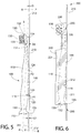
- the oral care implement 100 is positioned on the support member 210 with the rear surface 114 of the handle 110 adjacent to and at least partially in contact with the front surface 211 of the support member 210.
- a first portion 125 and a second portion 126 of the outer surface 122 of the handle 110 contact the front surface 211 of the support member 210.
- the first portion 125 contacts the support member 210 at the first point P1 and the second portion 126 contacts the support member 210 at the second point P2.
- the oral care implement 100 when the oral care implement 100 is positioned on the support member 210 having the front surface 211 which is planar, the outer periphery 155 of the distal end 152 of the flexible support element 150 is spaced apart from the front surface 211 of the support member 210 by a gap G1.
- the oral care implement 100 can be positioned within the package 200 while maintaining the entirety of the flexible support element 150 in spaced relation relative to the front surface 211 of the support member 210 upon which the oral care implement 100 rests.
- This feature prevents deformation of the flexible support element 150. Specifically, when the flexible support element 150 rests in contact with the support member 210, the flexible support element 150 can be pressed against the support member 210 with some force, thereby causing deformation of the flexible support element 150.
- the flexible support element 150 When the flexible support element 150 becomes deformed in its shape, it is unable to suction to a surface as desired. Thus, maintaining this elevated positioning of the flexible support element 150 relative to the support member 210 prevents such deformation from occurring during merchandising, sale, and storage.
- the cover member 220 is closely spaced relative to the tooth cleaning elements 135.
- the flexible support element 130 still would not be able to be pushed into contact with the front surface 211 of the support member 210 because to do so would require that the tooth cleaning elements 135 pivot away from the front surface 211 of the support member 210.
- the front surface 211 of the support member 210 extends along a plane P-P that is oblique to the longitudinal axis A-A of the handle 110 of the oral care implement 100.
- the plane P-P is identical to the reference plane RP1 described above.
- all of the description above with regard to the reference plane RP1 and its relationship to the longitudinal axes A-A, B-B is applicable to the plane P-P.
- the longitudinal axis A-A of the handle 110 and the front surface 211 of the support member 210 (and also the plane P-P) converge with distance from the flexible support element 150 in a direction towards the head 130 of the oral care implement 100.
- the longitudinal axis A-A of the handle 110 does not intersect the support member 210. Rather, the longitudinal axis A-A of the handle 110 and the plane P-P of the front surface 211 of the support member 210 intersect at a location that is beyond the distal end 132 of the head 130 of the oral care implement 100 and beyond a top edge 213 of the support member 210.
- the head 130 of the oral care implement 100 extends along the longitudinal axis B-B.
- the longitudinal axis B-B of the head 130 is oblique to the longitudinal axis A-A of the handle 110.
- the head 130 includes the front surface 133 from which the tooth cleaning elements 135 extend and the rear surface 134.
- the entirety of the rear surface 134 of the head 130 is spaced apart from the front surface 211 of the support member 210.
- the head 130 is angled away from the support member 210 with increasing distance from the handle 110, the distance (measured in a direction perpendicular to the front surface 211 of the support member 210) between the rear surface 134 of the head 130 and the front surface 211 of the support member 210 continuously increases from the proximal end 131 of the head 130 to the distal end 132 of the head 130.
- the distance between the rear surface 134 of the head 130 and the front surface 211 of the support member 210 is smallest at the proximal end 131 of the head 130.
- the distance D6 between the rear surface 134 of the head 130 and the front surface 211 of the support member 210 at the proximal end 131 of the head 130 is greater than the distance measured perpendicular to the front surface 211 of the support member 210 between the front surface 211 of the support member 210 and the outer periphery 155 of the flexible support element 150.
- both the head 130 of the oral care implement 100 and the flexible support element 150 of the oral care implement 100 are elevated or raised relative to the front surface 211 of the support member 210.
- both the head 130 and the flexible support element 150 are spaced apart from the front surface 211 of the support member 210 while the handle 110 contacts the front surface 211 of the support member 210 at two or more locations. This protects the flexible support element 150 against deformation as discussed above so that its functionality is viable after the oral care implement 100 is removed from the package 200.
Landscapes
- Engineering & Computer Science (AREA)
- Mechanical Engineering (AREA)
- Chemical & Material Sciences (AREA)
- Composite Materials (AREA)
- Brushes (AREA)
- Packages (AREA)
Abstract
Description
- Oral care implements such as toothbrushes are used daily to clean the interior surfaces of a user's mouth including the gums and the teeth. Because toothbrushes, and particularly the head portions thereof that have tooth cleaning elements extending therefrom, are inserted into a user's mouth during use, it is important to maintain them in a sanitary condition to avoid introducing bacteria into the user's mouth which can cause sickness. When an oral care implement is laid to rest against a countertop, there is the possibility that the tooth cleaning elements will contact germs or bacteria. Thus, it is desirable to maintain oral care implements in an upright/vertical position. One technique for achieving upright storage of an oral care implement is the use of a suction cup. However, there is difficulty in packaging an oral care implement with a suction cup without deforming the suction cup, which will render it ineffective at maintaining the oral care implement in the desired upright orientation. Thus, a need exists for a packaged oral care implement and an oral care implement thereof that overcomes the above-noted deficiencies.
- The present invention may be directed, in one aspect, to an oral care implement including a handle extending along a longitudinal axis, a head coupled to the proximal end of the handle, and a flexible support element coupled to the distal end of the handle. In one embodiment, a reference plane that is non-parallel to the longitudinal axis of the handle contacts the handle at a first point and a second point without intersecting the flexible support element. The first and second points may be separated from one another by a region of the handle that is not intersected or contacted by the reference plane. In one embodiment, the oral care implement may be positioned within a product retaining cavity of a package with a portion of the oral care implement in contact with a support member of the package. In such embodiment, the oral care implement may be positioned such that the flexible support element is raised within the package so that it does not contact the support member.
- In one aspect, the invention may be an oral care implement comprising: a handle extending along a longitudinal axis from a distal end to a proximal end and having a front surface and an opposite rear surface; a head coupled to the proximal end of the handle; a flexible support element coupled to the distal end of the handle; and wherein a reference plane that is non-parallel to the longitudinal axis of the handle is tangent to the handle at a first point and a second point without intersecting the flexible support element.
- In another aspect, the invention may be an oral care implement comprising: a handle extending along a longitudinal axis from a distal end to a proximal end and having an outer surface; a head coupled to the proximal end of the handle; a flexible support element coupled to the distal end of the handle; and wherein a reference plane that is non-parallel to the longitudinal axis of the handle contacts the outer surface of the handle at a first point and a second point without intersecting the flexible support element; and wherein a region of the outer surface of the handle located axially between the first and second points faces the reference plane without contacting the reference plane.
- In yet another aspect, the invention may be an oral care implement comprising: a handle extending along a longitudinal axis from a distal end to a proximal end and having an outer surface; a head coupled to the proximal end of the handle; a flexible support element coupled to the distal end of the handle; wherein a reference plane that is non-parallel to the longitudinal axis of the handle contacts the outer surface of the handle without penetrating the outer surface of the handle and without intersecting the flexible support element.
- In still another aspect, the invention may be an oral care implement comprising: a handle extending along a longitudinal axis; a head coupled to a first end of the handle; a flexible support element coupled to a second end of the handle; and wherein a reference plane that is non-parallel to the longitudinal axis of the handle contacts an outermost surface of the handle at multiple discrete locations without intersecting the flexible support element or the head.
- In a further aspect, the invention may be a packaged oral care implement comprising: a package comprising a support member and a product retaining cavity, the support member having a front surface; an oral care implement comprising a handle extending along a longitudinal axis from a distal end to a proximal end, a head coupled to the proximal end of the handle, and a flexible support element coupled to the distal end of the handle; wherein the oral care implement is positioned within the product retaining cavity with a portion of the handle in contact with the front surface of the support member; and wherein the flexible support element is spaced apart from the front surface of the support member.
- In a still further aspect, the invention can be an oral care implement comprising: a handle extending along a longitudinal axis from a distal end to a proximal end and having an outer surface; a flexible support element coupled to the distal end of the handle and being symmetric about the longitudinal axis of the handle; wherein a reference plane contacts the outer surface of the handle without penetrating the outer surface of the handle and without intersecting the flexible support element.
- Further areas of applicability of the present invention will become apparent from the detailed description provided hereinafter. It should be understood that the detailed description and specific examples, while indicating the preferred embodiment of the invention, are intended for purposes of illustration only and are not intended to limit the scope of the invention.
- The present invention will become more fully understood from the detailed description and the accompanying drawings, wherein:
-
Figure 1 is front view of an oral care implement in accordance with an embodiment of the present invention; -
Figure 2 is a side view of the oral care implement ofFIG. 1 ; -
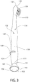
Figure 3 is a rear perspective view of the oral care implement ofFIG. 1 ; -
Figure 4 is a perspective view of the oral care implement ofFIG. 1 positioned within a package; -
Figure 5 is a side view of the oral care implement ofFIG. 1 positioned on a support member of the package ofFIG. 4 ; and -
Figure 6 is a side view of the packaged oral care implement ofFIG. 4 . - The following description of the preferred embodiment(s) is merely exemplary in nature and is in no way intended to limit the invention, its application, or uses.
- The description of illustrative embodiments according to principles of the present invention is intended to be read in connection with the accompanying drawings, which are to be considered part of the entire written description. In the description of embodiments of the invention disclosed herein, any reference to direction or orientation is merely intended for convenience of description and is not intended in any way to limit the scope of the present invention. Relative terms such as "lower," "upper," "horizontal," "vertical," "above," "below," "up," "down," "top" and "bottom" as well as derivatives thereof (e.g., "horizontally," "downwardly," "upwardly," etc.) should be construed to refer to the orientation as then described or as shown in the drawing under discussion. These relative terms are for convenience of description only and do not require that the apparatus be constructed or operated in a particular orientation unless explicitly indicated as such. Terms such as "attached," "affixed," "connected," "coupled," "interconnected," and similar refer to a relationship wherein structures are secured or attached to one another either directly or indirectly through intervening structures, as well as both movable or rigid attachments or relationships, unless expressly described otherwise. Moreover, the features and benefits of the invention are illustrated by reference to the exemplified embodiments. Accordingly, the invention expressly should not be limited to such exemplary embodiments illustrating some possible non-limiting combination of features that may exist alone or in other combinations of features; the scope of the invention being defined by the claims appended hereto.
- As used throughout, ranges are used as shorthand for describing each and every value that is within the range. Any value within the range can be selected as the terminus of the range. In addition, all references cited herein are hereby incorporated by reference in their entireties. In the event of a conflict in a definition in the present disclosure and that of a cited reference, the present disclosure controls.
- Referring to
Figures 1-3 concurrently, anoral care implement 100 is illustrated in accordance with an embodiment of the present invention. In the exemplified embodiment, theoral care implement 100 is in the form of a manual toothbrush. However, in certain other embodiments theoral care implement 100 can take on other forms such as being a powered toothbrush, a tongue scraper, a gum and soft tissue cleanser, a water pick, an interdental device, a tooth polisher, a specially designed ansate implement having cleaning elements, or any other type of implement that is commonly used for oral care. In some embodiments theoral care implement 100 may be any type of personal care implement, and not one that is specifically used for oral care, such as a deodorant application implement, a face or body cleaning implement, a razor, a hairbrush, or the like. Thus, the invention is not to be limited by the particular type of implement unless so specified in the claims. - The
oral care implement 100 generally comprises ahandle 110, ahead 130, and aflexible support element 150. Thehandle 110 extends from adistal end 111 to aproximal end 112 and has afront surface 113 and an oppositerear surface 114. Thehead 130 extends from aproximal end 131 to adistal end 132. Theflexible support element 150 extends from aproximal end 151 to adistal end 152. Thehead 130 is coupled to theproximal end 112 of thehandle 110. Theflexible support element 150 is coupled to thedistal end 111 of thehandle 110. - In the exemplified embodiment the
handle 110 and thehead 130 form an integral structure in that they are formed as a single, unitary component. Thehandle 110 is an elongated structure that provides the mechanism by which the user can hold and manipulate the oral care implement 100 during use. In the exemplified embodiment, thehandle 110 extends from theproximal end 111 to thedistal end 112 along a longitudinal axis A-A. Furthermore, in the exemplified embodiment thehandle 110 has an undulating shape that comprises aproximal section 115, adistal section 116, and aneck section 117. The proximal anddistal sections handle 110 that meet at awaist portion 118 of thehandle 110. Specifically, the proximal anddistal sections FIG. 1 ) and when viewed in side profile (FIG. 2 ). - The
waist portion 118 of thehandle 110 has a reduced transverse cross-sectional area relative to the proximal anddistal sections neck section 117 extends from thedistal section 116 to thedistal end 112 of thehandle 110. In the exemplified embodiment, theneck section 117 tapers/decreases in cross-sectional area as it extends from thedistal section 116 to thedistal end 112 of thehandle 110. Of course, the invention is not to be limited by the specific shape illustrated for thehandle 110 in all embodiments and in certain other embodiments thehandle 110 can take on a wide variety of shapes, contours, and configurations, none of which are limiting of the present invention unless so specified in the claims. - The
handle 110 may be formed of a hard or rigid plastic material, such as for example without limitation polymers and copolymers of ethylene, propylene, butadiene, vinyl compounds, and polyesters such as polyethylene terephthalate. Thehandle 110 may also include a grip that is formed of a resilient/elastomeric material, such as a thermoplastic elastomer. Such a grip may be molded over a portion of thehandle 110 that is typically gripped by a user's thumb and forefinger during use. Furthermore, it should be appreciated that additional regions of thehandle 110 can be overmolded with the resilient/elastomeric material to enhance the gripability of thehandle 110 during use. For example, portions of thehandle 110 that are typically gripped by a user's palm during use may be overmolded with a thermoplastic elastomer or other resilient material to further increase comfort to a user. Furthermore, materials other than those noted above can be used to form thehandle 110, including metal, wood, or any other desired material that has sufficient structural rigidity to permit a user to grip thehandle 110 and manipulate the oral care implement 100 during oral care activities such as toothbrushing or personal care activities such as facial cleansing. - The
head 130 of the oral care implement 100 is coupled to thehandle 110 and comprises afront surface 133 and an opposingrear surface 134. As noted above, thehead 130 may be formed integrally with thehandle 110 as a single unitary structure using a molding (i.e., injection molding), milling, machining, or other suitable process. Thus, thehead 130 may, in certain embodiments, be formed of any of the rigid plastic materials described above as being used for forming thehandle 110, although the invention is not to be so limited in all embodiments and other materials that are commonly used during toothbrush head manufacture may also be used. In other embodiments thehandle 110 and thehead 130 may be formed as separate components which are operably connected at a later stage of the manufacturing process by any suitable technique known in the art, including without limitation thermal or ultrasonic welding, a tight-fit assembly, a coupling sleeve, threaded engagement, adhesion, or fasteners. Furthermore, thehead 130 may be a separate component from thehandle 110 that is readily attachable thereto and detachable therefrom as desired. In this manner, thehead 130 may be a refill head such that thehead 130 can be replaced without replacing the entire oral care implement 100. - In the exemplified embodiment, a plurality of
tooth cleaning elements 135 are coupled to and extend from thehead 130 of the oral care implement 100. More specifically, in the exemplified embodiment thetooth cleaning elements 135 extend from thefront surface 133 of thehead 130. A tongue or soft tissue cleaner (not depicted) may be positioned on therear surface 134 of thehead 130. Such a tongue or soft tissue cleaner may be formed of an elastomeric material and may include protrusions, nubs, ridges, scrapers, or the like for engaging and cleaning a user's oral tissue surfaces. - The term "tooth cleaning elements" is used herein in a generic sense to refer to any structure that can be used to clean, polish, or wipe the teeth and/or soft oral tissue (e.g. tongue, cheek, gums, etc.) through relative surface contact. Common examples of "tooth cleaning elements" include, without limitation, bristle tufts, filament bristles, fiber bristles, nylon bristles, spiral bristles, rubber bristles, elastomeric protrusions, flexible polymer protrusions, combinations thereof and/or structures containing such materials or combinations. The tooth cleaning elements may include tapered bristles, non-tapered (i.e., end rounded) bristles, and combinations thereof. Any combination of the various types of tooth cleaning elements may be used on the oral care implement 100 in different embodiments. Thus, although the exemplified embodiment illustrates all of the
tooth cleaning elements 135 as bristle filaments, the invention is not to be so limited in all embodiments and bristle filaments alone, a combination of bristle filaments and rubber bristles, rubber bristles alone, or other combinations of the different tooth cleaning element types identified above may be used. - In embodiments that use elastomeric/rubber elements as one or more of the
tooth cleaning elements 135, suitable elastomeric materials may include any biocompatible resilient material suitable for uses in an oral hygiene apparatus. To provide optimum comfort as well as cleaning benefits, the elastomeric material of any such tooth or soft tissue engaging elements may have a hardness property in the range of A8 to A25 Shore hardness. One suitable elastomeric material is styrene-ethylene/butylene-styrene block copolymer (SEBS) manufactured by GLS Corporation. Nevertheless, SEBS material from other manufacturers or other materials within and outside the noted hardness range could be used. Thetooth cleaning elements 135 may be coupled to thehead 130 using any techniques known in the art, including without limitation staples, anchor-free tufting, in-mold tufting, AMR, or the like. The invention is not to be limited by the manner in which thetooth cleaning elements 135 are coupled to thehead 130 in all embodiments. - As noted above, the
flexible support element 150 is coupled to and extends from theproximal end 111 of thehandle 110. Theflexible support element 150 does not overlap with any portion of the length of thehandle 110, but rather it extends from theproximal end 111 of thehandle 110 only in a direction away from theproximal end 111 of the handle. Theflexible support element 150 is a natural extension of thehandle 110 in that the longitudinal axis A-A of thehandle 110 is also the longitudinal axis of theflexible support element 150. Thus, the longitudinal axis A-A of thehandle 110 extends through a center of theflexible support element 150. In the exemplified embodiment, thehandle 110 and theflexible support element 150 have a balanced appearance in that they are both symmetric about the longitudinal axis A-A. - The
distal end 152 of theflexible support element 150 forms the distalmost end of the oral care implement 100. Theflexible support element 150 has aninner surface 153 and anouter surface 154. Theinner surface 153 defines aninterior cavity 156 which is necessary for proper functionality and suctioning of theflexible support element 150. Furthermore, thedistal end 152 of theflexible support element 150 has anouter periphery 155 at theouter surface 154. In the exemplified embodiment thedistal end 152 of theflexible support element 150 has a round or ring-like shape. Thus, theflexible support element 150 has a circular transverse cross-sectional shape. - In the exemplified embodiment, the
flexible support element 150 is a suction cup that can be used to temporarily secure/fix the oral care implement 100 to a support surface. Theflexible support element 150 may be formed of an elastomeric material, such as a thermoplastic elastomer, that permits theflexible support element 150 to compress upon being pressed against a surface and to decompress back to its original shape upon no longer being pressed against the surface. Specifically, during use a person can press theflexible support element 150 onto a preferably nonporous surface and theinner surface 153 of theflexible support element 150 will move towards the surface, thereby removing the air between theflexible support element 150 and the surface. When pressure against theflexible support element 150 is removed, theflexible support element 150 will bias back into its original shape without permitting air to enter back into the space between theflexible support element 150 and the surface. This creates a vacuum that enables theflexible support element 150 to remain stuck to the surface. Specifically, the pressure difference between the atmosphere on the outside of theflexible support element 150 and the low-pressure cavity within theflexible support element 150 keeps theflexible support element 150 adhered to the surface. Theflexible support element 150 can be suctioned to a surface to maintain the oral care implement 100 in an orientation with the longitudinal axis A-A of thehandle 110 perpendicular to the surface. - As noted above, the
handle 110 of the oral care implement 100 extends along a longitudinal axis A-A. Furthermore, thehead 130 extends along a longitudinal axis B-B. The longitudinal axis of the head B-B is oblique to the longitudinal axis A-A of thehandle 110. Thus, thehead 130 is oriented at an angle relative to thehandle 110. Specifically, thehandle 130 is oriented so as to diverge from the longitudinal axis A-A of thehandle 110 with increasing distance from thedistal end 112 of thehandle 110. - In the exemplified embodiment, the
handle 110 comprises aprotuberance 119 extending from therear surface 114 thereof. Theprotuberance 119 has anouter surface 121 and terminates in adistal end 120. Therear surface 114 of thehandle 110 and theouter surface 121 of theprotuberance 119 collectively form anouter surface 122 of thehandle 110. In the exemplified embodiment, thedistal end 120 of the protuberance is a flat surface. However, the invention is not to be so limited and thedistal end 120 of theprotuberance 119 may be curved in other embodiments. In the exemplified embodiment, theprotuberance 119 is elongated along therear surface 114 of thehandle 110 in a direction transverse to the longitudinal axis A-A of thehandle 110. However, the invention is not to be so limited and theprotuberance 119 may be elongated in a direction parallel to the longitudinal axis A-A, or it may be a simple nub-like protrusion or multiple nub-like protrusions that are not elongated. Theprotuberance 119 may be formed integrally with the rigid plastic material of thehandle 110, or it may be formed as a part of an elastomeric overmold that is molded onto the rigid plastic material of thehandle 110. Theprotuberance 119 assists in ensuring that theflexible support element 150 does not become deformed when the oral care implement 100 is placed within a package or otherwise made to rest atop a flat surface in a horizontal orientation. When the oral care implement 100 is positioned on a horizontal surface with therear surface 114 of thehandle 110 facing the horizontal surface, theprotuberance 119 acts as a resting surface and is in direct surface contact with the horizontal surface. - In
FIG. 2 , a reference plane RP1 is illustrated that is non-parallel to the longitudinal axis A-A of thehandle 110. The reference plane RP1 is positioned adjacent to therear surface 114 of thehandle 110 and it contacts theouter surface 122 of the handle 110 (which, as discussed above, is formed by therear surface 114 of thehandle 110 and theouter surface 121 of the protuberance 119) at multiple locations. In the exemplified embodiment the reference plane RP1 contacts theouter surface 122 of thehandle 110 at two locations, although contact with theouter surface 122 of thehandle 110 at more than two locations is also possible within the scope of the present invention. Contact with theouter surface 122 of thehandle 110 at any given location is continuous and unbroken contact. Thus, if the reference plane RP1 contacts theouter surface 122 of thehandle 110, then breaks contact with theouter surface 122 of thehandle 110, and then contacts theouter surface 122 of thehandle 110 again at another location, this would constitute two separate and discrete contact locations. - In the exemplified embodiment, a region R1 of the
outer surface 122 of thehandle 110 located axially between the first and second points P1, P2 is devoid of contact with the reference plane RP1. Specifically, the region R1 of theouter surface 122 of thehandle 110 faces the reference plane RP1 without contacting it. Thus, for example, if the first and second points PI, P2 are on therear surface 114 of the handle 110 (or a protuberance extending therefrom), the region R1 would be a region of therear surface 114 of thehandle 110 that is between the first and second points P1, P2 that does not contact the reference plane RP1. In the exemplified embodiment the reference plane RP1 contacts theouter surface 122 of thehandle 110 without penetrating or passing through any portion of thehandle 110. Thus, in the exemplified embodiment the reference plane RP1 does not extend into the thickness of thehandle 110, or any part of the oral care implement 100, at any location. Rather, the reference plane RP1 merely comes into surface contact with theouter surface 122 of thehandle 110 at one or more locations without extending into thehandle 110. - Stated another way, the reference plane RP1 is tangent to the
handle 110 at a first point P1 on thehandle 110 and a second point P2 on thehandle 110. As used herein, the term "tangent" is not limited solely to a straight line or plane that touches a curve or curved surface at a point without crossing it at that point. Specifically, the term "tangent" also includes a line or plane that touches a flat or non-curved surface having a minimal length. For example, in the exemplified embodiment thedistal end 120 of theprotuberance 119 has a length measured in a direction of the longitudinal axis of between 0.5mm and 1.5mm. The reference plane RP1 contacts and extends along thedistal end 120 of theprotuberance 119 and is considered, as the term is used herein, to be tangent to thehandle 110 at that contact location. The term tangent may describe continuous contact between the reference plane RP1 and theouter surface 122 of thehandle 110 for up to about 3cm in some embodiments. Thus, the terms first point P1 and second point P2 could each refer to a single discrete point, or a single discrete location/region along thehandle 110 that is contacted by the reference plane RP1 in a continuous manner for a short distance relative to the overall length of the oral care implement 100. Whether the first and second points P1, P2 are single discrete points or regions, they are spaced apart by a region that is not contacted by the reference plane RP1. - In the exemplified embodiment, the reference plane RP1 is located adjacent to the
rear surface 114 of thehandle 110. However, the invention is not to be so limited in all embodiments and the reference plane RP1 could be adjacent to one of the lateral side surfaces of the handle 110 (between the front andrear surfaces protuberance 119 and the second point P2 is located on therear surface 114 of thehandle 110. Stated another way, theprotuberance 119, and specifically thedistal end 120 thereof, comprises the first point P1 and the second point P2 is located directly on therear surface 114 of thehandle 110. However, the invention is not to be so limited and theprotuberance 119 may be omitted in some embodiments and the shape of thehandle 110 modified to ensure that the reference plane RP1 is tangent to (or continuously contacts) thehandle 110 at two locations. As shown, the reference plane RP1 is tangent to thehandle 110 at the first and second points P1, P2 without intersecting any portion of theflexible support element 150 and without intersecting any portion of thehead 130. Furthermore, in the exemplified embodiment the reference plane RP1 is tangent to thehandle 110 at only the first and second points/locations P1, P2 and not at any other point/location, although as described above the invention is not limited to this embodiment only. - In the exemplified embodiment, the first point P1 is located a first distance D1 from the longitudinal axis A-A of the
handle 110 measured in a direction transverse to the longitudinal axis A-A of thehandle 110. Furthermore, the first point P1 is located a third distance D3 from thedistal end 152 of theflexible support element 150 measured in a direction parallel to the longitudinal axis A-A of thehandle 110. The second point P2 is located a second distance D2 from the longitudinal axis A-A of thehandle 110 measured in a direction transverse to the longitudinal axis A-A of thehandle 110. Furthermore, the second point P2 is located a fourth distance D4 from thedistal end 152 of theflexible support element 150 measured in a direction parallel to the longitudinal axis A-A of thehandle 110. - The
outer periphery 155 of thedistal end 152 of theflexible support element 150 forms a maximum outer diameter OD1 of theflexible support element 150. Theouter periphery 155 of thedistal end 152 of theflexible support element 150 is spaced a fifth distance D5 from the longitudinal axis A-A of thehandle 110 measured in a direction transverse to the longitudinal axis A-A of thehandle 110. In the exemplified embodiment, the longitudinal axis A-A of thehandle 110 passes exactly through the center of theflexible support element 150, and thus the fifth distance D5 is equal to the radius of thedistal end 152 of the flexible support element 150 (or one-half of the maximum outer diameter OD1 of the flexible support element 150). - The
handle 100 of the oral care implement 100 has a first maximum thickness T1 measured between the front andrear surfaces handle 110 and a second maximum thickness T2 measured between opposing side surfaces of the handle 110 (i.e., measured along the front andrear surfaces flexible support element 150 is greater than the first maximum thickness T1 and the second maximum thickness T2. - In the exemplified embodiment, the fifth distance D5 is greater than the first distance D1, and the first distance D1 is greater than the second distance D2. Thus, the
outer periphery 155 of thedistal end 152 of theflexible support element 150 is located further from the longitudinal axis A-A of thehandle 110 than the point P1, and the point P1 is located further from the longitudinal axis A-A of thehandle 110 than the point P2. Furthermore, the distance D4 from thedistal end 152 of theflexible support element 150 to point P2 is greater than the distance D3 from thedistal end 152 of theflexible support element 150 to point P1. As a result, if the oral care implement 100 were laying on a planar surface that is coincident with the reference plane RP1, the longitudinal axis A-A of thehandle 110 would converge towards the reference plane RP1 as it extends from thedistal end 111 of thehandle 110 towards theproximal end 112 of thehandle 110. As discussed in greater detail below with reference toFIGS. 4-6 , this enables theflexible support element 150 to be raised/elevated relative to a support member when the oral care implement 100 is placed within a package or raised/elevated relative to a horizontal surface when the oral care implement 100 is resting thereon in a somewhat horizontal orientation. - In the exemplified embodiment, a ratio of a length of the oral care implement 100 to the third distance D3 between a
distal end 152 of theflexible support element 150 and the first point P1 is between 4:1 and 4.5:1, and a ratio of the length of the oral care implement 100 to a fourth distance D4 between thedistal end 152 of theflexible support element 150 and the second point P2 is between 1.5:1 and 2.0. When laying the oral care implement 100 in a horizontal position (with the longitudinal axis A-A lying substantially horizontally) on a support surface, the point P1 will contact the support surface first because it extends further from the longitudinal axis A-A than the point P2. Then, because a majority of the oral care implement 100 is located between the first point P1 and thedistal end 132 of thehead 130, the upper portion of thehandle 110 and thehead 130 will pivot rearward towards the support surface (due to a greater amount of the total weight of the oral care implement 100 being on that side of the point P1, which forms a pivot point. This results in theflexible support element 150 being elevated relative to the support surface. - As best illustrated in
FIG. 2 , the longitudinal axis A-A of thehandle 110 and the reference plane RP1 converge with distance from theflexible support element 150 towards thehead 130 without intersecting at any position along the length of the oral care implement 100. Thus, the intersection of the longitudinal axis A-A and the reference plane RP1 will occur at some location beyond the head 130 (beyond thedistal end 132 of thehead 130 in a direction away from thehandle 110 and the flexible support element 150) which is not illustrated in the exemplified embodiment. As noted above, thehead 130 extends along the longitudinal axis B-B which is oblique to the longitudinal axis A-A of thehandle 110 such that thehead 130 is angled away from the reference plane RP1 as it extends from thehandle 110 towards thedistal end 132 of thehead 130. Furthermore, the longitudinal axis B-B of thehead 130 intersects the longitudinal axis A-A of thehandle 110 at a first location L1 along the length of the oral care implement 100 and the longitudinal axis B-B of thehead 130 intersects the reference plane RP1 at a second location L2 along the length of the oral care implement 100. The first location L1 is closer to thehead 130 than the second location L2, which is closer to theflexible support element 150. Furthermore, the first location L1 is axially between the second point P2 and thedistal end 132 of thehead 130. The second location L2 is axially between the first point P1 and the second point P2. - Referring now to
FIG. 4 , the oral care implement 100 is illustrated positioned within apackage 200, thereby forming a packaged oral care implement 300. Thepackage 200 comprises asupport member 210 and acover member 220. Thepackage 200 in the exemplified embodiment is a blister package, although it may be modified to a clamshell package or some other type of package commonly used for holding oral care implements during sale thereof. - The
support member 210 may, in one embodiment, be formed of a paper material such as cardboard, posterboard, other relatively thick paper products, plastic, film, combinations thereof, or other suitable material. Thesupport member 210 can be a single layer or a multi-layer laminate. Thesupport member 210 may be flexible in some embodiments, but may be rigid or semi-rigid in other embodiments. - In the exemplified embodiment, the
cover member 220 is coupled to thesupport member 210 to define aproduct retaining cavity 230 therebetween. Furthermore, thecover member 220 is transparent in the exemplified embodiment to permit the oral care implement 100 to be visible therethrough. However, thecover member 220 may be translucent, colored, patterned, or the like in other embodiments. Thecover member 220 is shaped so as to comprise a three-dimensional contour that may, in certain embodiments, correspond in size and shape to the oral care implement 100. The three-dimensional contour need not correspond in shape to the oral care implements 100 in all embodiments and it may just define theproduct retaining cavity 230 having a generic shape (i.e., rectangular or the like). - In one embodiment, the
cover member 220 may be formed from a thermoformed plastic film. Suitable thermoformed plastic films may be constructed of such material as polyethyleneterephthalate (PETA, PETG, PETGAG), polyvinylchloride (PVC), polypropylene (PP) or styrol-butadiene-block copolymer (SBS), preferred PVC. Other suitable materials of construction for the thermoformed plastic film include, without limitation, renewable primary products, for example of cornstarch, sugar (polyhydroxybutyrat/-valerat), cellulose diacetate, cellulose nitrate, polyactid (PLA), and polyhydroxybutyrat (PHB). - Referring to
FIGS. 4-6 concurrently, thesupport member 210 has afront surface 211 and an oppositerear surface 212. In the exemplified embodiment, thesupport member 210 is illustrated as having a flat, planarfront surface 211 and a flat, planarrear surface 212. Of course, in other embodiments one or both of the front andrear surfaces support member 210 may have various contours, three-dimensional regions or the like. Thesupport member 210 may comprise product information, such as indicia that provide information to a consumer about the oral care implement 100 that is contained within thefirst package 110 of the manufacturer thereof. Such indicia may include instructions, logos, advertisements, and/or other marketing information. All or a portion of thesupport member 210 can be opaque so that the product information can be effectively conveyed to the consumer. Thecover member 220 may also comprise such indicia either directly printed thereon or in the form of a sticker that is adhered thereto. - The
cover member 220 has aninner surface 221 and anouter surface 222. Theinner surface 221 of thecover member 220 and thefront surface 211 of thesupport member 210 collectively define and bound theproduct retaining cavity 230. In certain embodiments, thecover member 220 may form a front cover and a rear cover of thepackage 110. In such an embodiment, thesupport member 210 may be located within the cavity formed between the front and rear covers of thecover member 220 alongside of the oral care implement 100. Thus, in such an embodiment the front and rear covers of thecover member 220 are coupled together to form a cavity for receiving the oral care implement 100, and thesupport member 210 is positioned within the cavity. In such embodiments, at least a portion of thesupport member 210 may be visible through thecover member 220 due to the transparent nature of thecover member 220. - As best seen in
FIG. 5 , the oral care implement 100 is positioned on thesupport member 210 with therear surface 114 of thehandle 110 adjacent to and at least partially in contact with thefront surface 211 of thesupport member 210. When so positioned, afirst portion 125 and asecond portion 126 of theouter surface 122 of thehandle 110 contact thefront surface 211 of thesupport member 210. Specifically, thefirst portion 125 contacts thesupport member 210 at the first point P1 and thesecond portion 126 contacts thesupport member 210 at the second point P2. - Furthermore, when the oral care implement 100 is positioned on the
support member 210 having thefront surface 211 which is planar, theouter periphery 155 of thedistal end 152 of theflexible support element 150 is spaced apart from thefront surface 211 of thesupport member 210 by a gap G1. Thus, the oral care implement 100 can be positioned within thepackage 200 while maintaining the entirety of theflexible support element 150 in spaced relation relative to thefront surface 211 of thesupport member 210 upon which the oral care implement 100 rests. This feature prevents deformation of theflexible support element 150. Specifically, when theflexible support element 150 rests in contact with thesupport member 210, theflexible support element 150 can be pressed against thesupport member 210 with some force, thereby causing deformation of theflexible support element 150. When theflexible support element 150 becomes deformed in its shape, it is unable to suction to a surface as desired. Thus, maintaining this elevated positioning of theflexible support element 150 relative to thesupport member 210 prevents such deformation from occurring during merchandising, sale, and storage. - As seen in
FIG. 6 , thecover member 220 is closely spaced relative to thetooth cleaning elements 135. Thus, if a consumer or other individual were to push downwardly on theflexible support element 130 in the direction of thesupport member 210 while the oral care implement 100 is contained in thepackage 200, theflexible support element 130 still would not be able to be pushed into contact with thefront surface 211 of thesupport member 210 because to do so would require that thetooth cleaning elements 135 pivot away from thefront surface 211 of thesupport member 210. However, in the exemplified embodiment there is insufficient spacing within thepackage 200 between thetooth cleaning elements 135 and theinner surface 211 of thecover member 220 to enable theflexible support element 150 to be forcibly pressed into contact with thefront surface 211 of thesupport member 210. - Referring to
FIGS. 5 and 6 concurrently, thefront surface 211 of thesupport member 210 extends along a plane P-P that is oblique to the longitudinal axis A-A of thehandle 110 of the oral care implement 100. Specifically, the plane P-P is identical to the reference plane RP1 described above. Thus, all of the description above with regard to the reference plane RP1 and its relationship to the longitudinal axes A-A, B-B is applicable to the plane P-P. The longitudinal axis A-A of thehandle 110 and thefront surface 211 of the support member 210 (and also the plane P-P) converge with distance from theflexible support element 150 in a direction towards thehead 130 of the oral care implement 100. However, in the exemplified embodiment the longitudinal axis A-A of thehandle 110 does not intersect thesupport member 210. Rather, the longitudinal axis A-A of thehandle 110 and the plane P-P of thefront surface 211 of thesupport member 210 intersect at a location that is beyond thedistal end 132 of thehead 130 of the oral care implement 100 and beyond atop edge 213 of thesupport member 210. - The longitudinal axis A-A of the
handle 110 and the plane P-P of thefront surface 211 of the support member 210 (and the reference plane RP1 which is coincident with the plane P-P) intersect at an angle θ of between 2° and 10°, more specifically between 2° and 7°, and still more specifically between 2° and 4°, and even more specifically between 2° and 3°. This is sufficient to ensure that theflexible support element 150 is elevated within the package to prevent deformation thereof as discussed herein. - As discussed above, the
head 130 of the oral care implement 100 extends along the longitudinal axis B-B. The longitudinal axis B-B of thehead 130 is oblique to the longitudinal axis A-A of thehandle 110. Thehead 130 includes thefront surface 133 from which thetooth cleaning elements 135 extend and therear surface 134. In the exemplified embodiment, the entirety of therear surface 134 of thehead 130 is spaced apart from thefront surface 211 of thesupport member 210. Furthermore, because thehead 130 is angled away from thesupport member 210 with increasing distance from thehandle 110, the distance (measured in a direction perpendicular to thefront surface 211 of the support member 210) between therear surface 134 of thehead 130 and thefront surface 211 of thesupport member 210 continuously increases from theproximal end 131 of thehead 130 to thedistal end 132 of thehead 130. Thus, the distance between therear surface 134 of thehead 130 and thefront surface 211 of thesupport member 210 is smallest at theproximal end 131 of thehead 130. However, the distance D6 between therear surface 134 of thehead 130 and thefront surface 211 of thesupport member 210 at theproximal end 131 of thehead 130 is greater than the distance measured perpendicular to thefront surface 211 of thesupport member 210 between thefront surface 211 of thesupport member 210 and theouter periphery 155 of theflexible support element 150. - Thus, when the oral care implement 100 is positioned within the
package 200, both thehead 130 of the oral care implement 100 and theflexible support element 150 of the oral care implement 100 are elevated or raised relative to thefront surface 211 of thesupport member 210. Stated another way, both thehead 130 and theflexible support element 150 are spaced apart from thefront surface 211 of thesupport member 210 while thehandle 110 contacts thefront surface 211 of thesupport member 210 at two or more locations. This protects theflexible support element 150 against deformation as discussed above so that its functionality is viable after the oral care implement 100 is removed from thepackage 200. - While the invention has been described with respect to specific examples including presently preferred modes of carrying out the invention, those skilled in the art will appreciate that there are numerous variations and permutations of the above described systems and techniques. It is to be understood that other embodiments may be utilized and structural and functional modifications may be made without departing from the scope of the present invention. Thus, the spirit and scope of the invention should be construed broadly as set forth in the appended claims.
Claims (15)
- An oral care implement comprising:a handle extending along a longitudinal axis from a distal end to a proximal end and having an outer surface;a head coupled to the proximal end of the handle;a flexible support element coupled to the distal end of the handle; andwherein a reference plane that is non-parallel to the longitudinal axis of the handle contacts the outer surface of the handle without penetrating the outer surface of the handle and without intersecting the flexible support element.
- The oral care implement according to claim 1 wherein the reference plane contacts the outer surface of the handle at a first point and a second point, and wherein a region of the outer surface of the handle located axially between the first and second points faces the reference plane without contacting the reference plane.
- The oral care implement according to claim 2 wherein the reference plane is tangent to the handle at one or both of the first point and the second point.
- The oral care implement according to claim 2 or claim 3 wherein the first point is spaced a first distance from the longitudinal axis of the handle and the second point is spaced a second distance from the longitudinal axis of the handle, each of the first and second distances being measured in a direction transverse to the longitudinal axis of the handle, and wherein the first distance is greater than the second distance.
- The oral care implement according to claim 4 wherein the first point is located a third distance from a distal end of the flexible support element and the second point is located a fourth distance from the distal end of the flexible support element, the third and fourth distances being measured in a direction parallel to the longitudinal axis of the handle, and wherein the fourth distance is greater than the third distance such that the first point is located axially between the flexible support element and the second point.
- The oral care implement according to any one of claim 4 or claim 5 wherein the distal end of the flexible support element has an outer periphery, the flexible support element having a maximum outer diameter at the outer periphery of the distal end, and wherein the outer periphery of the distal end of the flexible support element is spaced a fifth distance from the longitudinal axis of the handle measured in a direction transverse to the longitudinal axis of the handle, the fifth distance being greater than the first distance.
- The oral care implement according to any one of claims 2 to 6 wherein the handle comprises a front surface, an opposite rear surface, and a protuberance extending from the rear surface of the handle and terminating at a distal end, and wherein the distal end of the protuberance comprises the first point and the second point is located directly on the rear surface of the handle.
- The oral care implement according to any preceding claim wherein the longitudinal axis of the handle and the reference plane converge with distance from the flexible support element towards the head without intersecting at any position along a length of the oral care implement.
- The oral care implement according to any preceding claim wherein the head comprises a front surface and an opposite rear surface, and further comprising a plurality of tooth cleaning elements extending from the front surface of the head, wherein the handle comprises a front surface and a rear surface that collectively form the outer surface of the handle, the reference plane contacting and facing the rear surface of the handle, and wherein the reference plane does not intersect the head or the tooth cleaning elements.
- The oral care implement according to any preceding claim wherein the handle and the flexible support element are symmetric about the longitudinal axis.
- A packaged oral care implement comprising:a package comprising a support member and a product retaining cavity, the support member having a front surface;an oral care implement comprising a handle extending along a longitudinal axis from a distal end to a proximal end, a head coupled to the proximal end of the handle, and a flexible support element coupled to the distal end of the handle;wherein the oral care implement is positioned within the product retaining cavity with a portion of the handle in contact with the front surface of the support member; andwherein the flexible support element is spaced apart from the front surface of the support member.
- The packaged oral care implement according to claim 11 wherein the front surface of the support member extends along a plane that is oblique to the longitudinal axis of the handle of the oral care implement.
- The packaged oral care implement according to claim 11 or claim 12 further comprising a protuberance extending from a rear surface of the handle, wherein the protuberance and a portion of the rear surface of the handle are the only two points of contact between the oral care implement and the support member.
- The packaged oral care implement according to any one of claims 11 to 13 wherein the package further comprises a cover member coupled to the support member, the product retention cavity being formed between the front surface of the support member and an inner surface of the cover member.
- The packaged oral care implement according to any one of claims 11 to 14 wherein the longitudinal axis of the handle and the front surface of the support member converge with distance from the flexible support element in a direction of the head without intersecting.
Applications Claiming Priority (1)
| Application Number | Priority Date | Filing Date | Title |
|---|---|---|---|
| US15/345,176 US10172445B2 (en) | 2016-11-07 | 2016-11-07 | Packaged oral care implement and oral care implement thereof |
Publications (3)
| Publication Number | Publication Date |
|---|---|
| EP3318160A2 true EP3318160A2 (en) | 2018-05-09 |
| EP3318160A3 EP3318160A3 (en) | 2018-06-06 |
| EP3318160B1 EP3318160B1 (en) | 2020-09-16 |
Family
ID=60043053
Family Applications (1)
| Application Number | Title | Priority Date | Filing Date |
|---|---|---|---|
| EP17195357.3A Active EP3318160B1 (en) | 2016-11-07 | 2017-10-09 | Oral care implement |
Country Status (3)
| Country | Link |
|---|---|
| US (1) | US10172445B2 (en) |
| EP (1) | EP3318160B1 (en) |
| CN (1) | CN108065582B (en) |
Families Citing this family (7)
| Publication number | Priority date | Publication date | Assignee | Title |
|---|---|---|---|---|
| USD776937S1 (en) * | 2015-07-23 | 2017-01-24 | Colgate-Palmolive Company | Oral care implement |
| USD776436S1 (en) * | 2015-07-23 | 2017-01-17 | Colgate-Palmolive Company | Oral care implement |
| USD838110S1 (en) * | 2017-10-26 | 2019-01-15 | Shummi Enterprise Co., Ltd. | Toothbrush |
| EP3603906B1 (en) * | 2018-07-31 | 2021-12-15 | BIC Violex S.A. | Razor handles |
| EP3827700A1 (en) | 2019-11-27 | 2021-06-02 | Trisa Holding AG | Oral care implement |
| USD919301S1 (en) * | 2020-07-06 | 2021-05-18 | Thumbs Up Innovations Technology Co., Ltd. | Brush head |
| US20230413990A1 (en) * | 2020-11-16 | 2023-12-28 | Colgate-Palmolive Company | Stand for an Oral Care Implement, Oral Care Implement System Including the Same, and Related Method |
Family Cites Families (33)
| Publication number | Priority date | Publication date | Assignee | Title |
|---|---|---|---|---|
| US1899242A (en) | 1932-03-02 | 1933-02-28 | Mcnab Alexander | Toothbrush holder |
| GR1002012B (en) | 1993-02-16 | 1995-10-30 | Johnson & Johnson Consumer | Self-standing toothbrush |
| GB2284542B (en) | 1993-12-13 | 1998-01-21 | Boon Su Chan | A double-headed toothbrush |
| US5742971A (en) | 1995-11-30 | 1998-04-28 | Salinger; Stephen Forrest | Suction cup toothbrush |
| US5875510A (en) | 1996-09-27 | 1999-03-02 | Chesebrough-Pond's Usa Co., Division Of Conopco, Inc. | Replaceable head toothbrush |
| US5881421A (en) | 1997-03-20 | 1999-03-16 | Ducharme; Jean Claude | Denture cleaning brush |
| US6564940B2 (en) | 1998-09-30 | 2003-05-20 | The Procter & Gamble Company | Electric toothbrush |
| USD456136S1 (en) | 2000-07-11 | 2002-04-30 | Mam Babyartikel Gesellschaft M.B.H. | Toothbrush |
| US20020100134A1 (en) | 2001-01-31 | 2002-08-01 | Steven Dunn | Suction cup toothbrush with improved characteristics |
| USD462178S1 (en) | 2001-09-11 | 2002-09-03 | Colgate-Palmolive Company | Toothbrush |
| US20030166373A1 (en) | 2002-03-04 | 2003-09-04 | The Procter & Gamble Co. | Toothbrush kit |
| US7047591B2 (en) | 2002-09-20 | 2006-05-23 | Colgate-Palmolive Company | Oral care implement |
| USD532202S1 (en) | 2003-09-04 | 2006-11-21 | Colgate-Palmolive Company | Set of bristles for a toothbrush |
| CN100347055C (en) | 2002-09-05 | 2007-11-07 | 高露洁-棕榄公司 | Toothbrush package |
| DE10245086A1 (en) | 2002-09-27 | 2004-04-08 | Trisa Holding Ag | Method of making a toothbrush |
| WO2004089154A1 (en) * | 2003-04-04 | 2004-10-21 | Honzo Seiyaku Kabushiki Kaisha | Tooth brush |
| USD513126S1 (en) | 2003-07-03 | 2005-12-27 | Colgate-Palmolive Company | Children's toothbrush |
| USD505264S1 (en) | 2003-08-26 | 2005-05-24 | World Trend, Inc. | Toothbrush |
| USD510808S1 (en) | 2004-04-15 | 2005-10-25 | Glaxosmithkline Consumer Healthcare Gmbh & Co. Kg | Toothbrush |
| AU308408S (en) | 2006-04-21 | 2006-08-07 | Barros Laboratories Pty Ltd | A toothbrush |
| USD566400S1 (en) | 2007-06-21 | 2008-04-15 | Inhomevations | Combined banana-shaped toothbrush and teether for infants |
| JP5606328B2 (en) | 2008-02-08 | 2014-10-15 | コルゲート・パーモリブ・カンパニー | Oral care toothbrush |
| US8079109B2 (en) | 2008-09-02 | 2011-12-20 | Sunstar Americas, Inc. | Illuminated toothbrush |
| US8245844B2 (en) | 2009-03-16 | 2012-08-21 | Colgate-Palmolive Company | Display package |
| US20110016651A1 (en) | 2009-07-21 | 2011-01-27 | Robert Piserchio | Pressure-sensitive toothbrush |
| WO2011014415A1 (en) | 2009-07-31 | 2011-02-03 | Colgate-Palmolive Company | High cleaning dentifrice compositions |
| EP2361528A1 (en) | 2010-02-26 | 2011-08-31 | Trisa Holding AG | Oral hygiene device, in particular toothbrush, and method for its production |
| EP2651774B1 (en) | 2010-12-13 | 2015-07-15 | Colgate-Palmolive Company | Easy opening display package for merchandise |
| DE102011011323A1 (en) | 2011-02-16 | 2012-08-16 | Interbros Gmbh | Mouth or tooth cleaning device |
| WO2014099718A1 (en) | 2012-12-21 | 2014-06-26 | Carlon Holdings Llc | Omnidirectional oral care brush |
| CN203538668U (en) * | 2013-07-10 | 2014-04-16 | 舒美兴业股份有限公司 | Luminous Toothbrush Structure |
| US20170013952A1 (en) | 2015-07-17 | 2017-01-19 | Shummi Enterprise Co., Ltd. | Touch-control flashing toothbrush |
| USD776436S1 (en) * | 2015-07-23 | 2017-01-17 | Colgate-Palmolive Company | Oral care implement |
-
2016
- 2016-11-07 US US15/345,176 patent/US10172445B2/en active Active
-
2017
- 2017-10-09 EP EP17195357.3A patent/EP3318160B1/en active Active
- 2017-10-27 CN CN201711031234.2A patent/CN108065582B/en not_active Expired - Fee Related
Non-Patent Citations (1)
| Title |
|---|
| None |
Also Published As
| Publication number | Publication date |
|---|---|
| CN108065582A (en) | 2018-05-25 |
| EP3318160B1 (en) | 2020-09-16 |
| US10172445B2 (en) | 2019-01-08 |
| EP3318160A3 (en) | 2018-06-06 |
| US20180125225A1 (en) | 2018-05-10 |
| CN108065582B (en) | 2020-06-16 |
Similar Documents
| Publication | Publication Date | Title |
|---|---|---|
| EP3318160B1 (en) | Oral care implement | |
| US11771210B2 (en) | Oral care implement | |
| US10595628B2 (en) | Oral care implement | |
| TWI481362B (en) | Oral health equipment | |
| US9505540B2 (en) | Packaged oral care implement and package | |
| EP1539025B1 (en) | Improved electric toothbrush housing design | |
| US11229281B2 (en) | Oral care implement | |
| EP2811860B1 (en) | A toothbrush in a display package. | |
| US11490725B2 (en) | Packaged personal care implement | |
| US10112760B2 (en) | Packaged oral care implement and package | |
| HK1201426B (en) | Oral care instrument and package therefore | |
| TW201534248A (en) | Oral care implement with applicator |
Legal Events
| Date | Code | Title | Description |
|---|---|---|---|
| PUAI | Public reference made under article 153(3) epc to a published international application that has entered the european phase |
Free format text: ORIGINAL CODE: 0009012 |
|
| STAA | Information on the status of an ep patent application or granted ep patent |
Free format text: STATUS: THE APPLICATION HAS BEEN PUBLISHED |
|
| PUAL | Search report despatched |
Free format text: ORIGINAL CODE: 0009013 |
|
| AK | Designated contracting states |
Kind code of ref document: A2 Designated state(s): AL AT BE BG CH CY CZ DE DK EE ES FI FR GB GR HR HU IE IS IT LI LT LU LV MC MK MT NL NO PL PT RO RS SE SI SK SM TR |
|
| AX | Request for extension of the european patent |
Extension state: BA ME |
|
| AK | Designated contracting states |
Kind code of ref document: A3 Designated state(s): AL AT BE BG CH CY CZ DE DK EE ES FI FR GB GR HR HU IE IS IT LI LT LU LV MC MK MT NL NO PL PT RO RS SE SI SK SM TR |
|
| AX | Request for extension of the european patent |
Extension state: BA ME |
|
| RIC1 | Information provided on ipc code assigned before grant |
Ipc: B65D 75/00 20060101ALI20180502BHEP Ipc: A46B 9/04 20060101AFI20180502BHEP |
|
| STAA | Information on the status of an ep patent application or granted ep patent |
Free format text: STATUS: REQUEST FOR EXAMINATION WAS MADE |
|
| 17P | Request for examination filed |
Effective date: 20181206 |
|
| RBV | Designated contracting states (corrected) |
Designated state(s): AL AT BE BG CH CY CZ DE DK EE ES FI FR GB GR HR HU IE IS IT LI LT LU LV MC MK MT NL NO PL PT RO RS SE SI SK SM TR |
|
| STAA | Information on the status of an ep patent application or granted ep patent |
Free format text: STATUS: EXAMINATION IS IN PROGRESS |
|
| 17Q | First examination report despatched |
Effective date: 20190123 |
|
| GRAP | Despatch of communication of intention to grant a patent |
Free format text: ORIGINAL CODE: EPIDOSNIGR1 |
|
| STAA | Information on the status of an ep patent application or granted ep patent |
Free format text: STATUS: GRANT OF PATENT IS INTENDED |
|
| RIC1 | Information provided on ipc code assigned before grant |
Ipc: B65D 75/36 20060101ALI20200304BHEP Ipc: B65D 75/00 20060101ALI20200304BHEP Ipc: A46B 15/00 20060101ALI20200304BHEP Ipc: A46B 5/02 20060101ALI20200304BHEP Ipc: A46B 9/04 20060101AFI20200304BHEP |
|
| INTG | Intention to grant announced |
Effective date: 20200325 |
|
| RIN1 | Information on inventor provided before grant (corrected) |
Inventor name: WAINLESS, DANIEL |
|
| GRAS | Grant fee paid |
Free format text: ORIGINAL CODE: EPIDOSNIGR3 |
|
| GRAA | (expected) grant |
Free format text: ORIGINAL CODE: 0009210 |
|
| STAA | Information on the status of an ep patent application or granted ep patent |
Free format text: STATUS: THE PATENT HAS BEEN GRANTED |
|
| AK | Designated contracting states |
Kind code of ref document: B1 Designated state(s): AL AT BE BG CH CY CZ DE DK EE ES FI FR GB GR HR HU IE IS IT LI LT LU LV MC MK MT NL NO PL PT RO RS SE SI SK SM TR |
|
| REG | Reference to a national code |
Ref country code: GB Ref legal event code: FG4D |
|
| REG | Reference to a national code |
Ref country code: CH Ref legal event code: EP |
|
| REG | Reference to a national code |
Ref country code: DE Ref legal event code: R096 Ref document number: 602017023651 Country of ref document: DE |
|
| REG | Reference to a national code |
Ref country code: IE Ref legal event code: FG4D |
|
| REG | Reference to a national code |
Ref country code: AT Ref legal event code: REF Ref document number: 1313322 Country of ref document: AT Kind code of ref document: T Effective date: 20201015 |
|
| PG25 | Lapsed in a contracting state [announced via postgrant information from national office to epo] |
Ref country code: HR Free format text: LAPSE BECAUSE OF FAILURE TO SUBMIT A TRANSLATION OF THE DESCRIPTION OR TO PAY THE FEE WITHIN THE PRESCRIBED TIME-LIMIT Effective date: 20200916 Ref country code: BG Free format text: LAPSE BECAUSE OF FAILURE TO SUBMIT A TRANSLATION OF THE DESCRIPTION OR TO PAY THE FEE WITHIN THE PRESCRIBED TIME-LIMIT Effective date: 20201216 Ref country code: GR Free format text: LAPSE BECAUSE OF FAILURE TO SUBMIT A TRANSLATION OF THE DESCRIPTION OR TO PAY THE FEE WITHIN THE PRESCRIBED TIME-LIMIT Effective date: 20201217 Ref country code: FI Free format text: LAPSE BECAUSE OF FAILURE TO SUBMIT A TRANSLATION OF THE DESCRIPTION OR TO PAY THE FEE WITHIN THE PRESCRIBED TIME-LIMIT Effective date: 20200916 Ref country code: SE Free format text: LAPSE BECAUSE OF FAILURE TO SUBMIT A TRANSLATION OF THE DESCRIPTION OR TO PAY THE FEE WITHIN THE PRESCRIBED TIME-LIMIT Effective date: 20200916 Ref country code: NO Free format text: LAPSE BECAUSE OF FAILURE TO SUBMIT A TRANSLATION OF THE DESCRIPTION OR TO PAY THE FEE WITHIN THE PRESCRIBED TIME-LIMIT Effective date: 20201216 |
|
| PGFP | Annual fee paid to national office [announced via postgrant information from national office to epo] |
Ref country code: FR Payment date: 20201026 Year of fee payment: 4 |
|
| REG | Reference to a national code |
Ref country code: AT Ref legal event code: MK05 Ref document number: 1313322 Country of ref document: AT Kind code of ref document: T Effective date: 20200916 |
|
| REG | Reference to a national code |
Ref country code: NL Ref legal event code: MP Effective date: 20200916 |
|
| PG25 | Lapsed in a contracting state [announced via postgrant information from national office to epo] |
Ref country code: LV Free format text: LAPSE BECAUSE OF FAILURE TO SUBMIT A TRANSLATION OF THE DESCRIPTION OR TO PAY THE FEE WITHIN THE PRESCRIBED TIME-LIMIT Effective date: 20200916 Ref country code: RS Free format text: LAPSE BECAUSE OF FAILURE TO SUBMIT A TRANSLATION OF THE DESCRIPTION OR TO PAY THE FEE WITHIN THE PRESCRIBED TIME-LIMIT Effective date: 20200916 |
|
| REG | Reference to a national code |
Ref country code: LT Ref legal event code: MG4D |
|
| PG25 | Lapsed in a contracting state [announced via postgrant information from national office to epo] |
Ref country code: SM Free format text: LAPSE BECAUSE OF FAILURE TO SUBMIT A TRANSLATION OF THE DESCRIPTION OR TO PAY THE FEE WITHIN THE PRESCRIBED TIME-LIMIT Effective date: 20200916 Ref country code: EE Free format text: LAPSE BECAUSE OF FAILURE TO SUBMIT A TRANSLATION OF THE DESCRIPTION OR TO PAY THE FEE WITHIN THE PRESCRIBED TIME-LIMIT Effective date: 20200916 Ref country code: RO Free format text: LAPSE BECAUSE OF FAILURE TO SUBMIT A TRANSLATION OF THE DESCRIPTION OR TO PAY THE FEE WITHIN THE PRESCRIBED TIME-LIMIT Effective date: 20200916 Ref country code: PT Free format text: LAPSE BECAUSE OF FAILURE TO SUBMIT A TRANSLATION OF THE DESCRIPTION OR TO PAY THE FEE WITHIN THE PRESCRIBED TIME-LIMIT Effective date: 20210118 Ref country code: CZ Free format text: LAPSE BECAUSE OF FAILURE TO SUBMIT A TRANSLATION OF THE DESCRIPTION OR TO PAY THE FEE WITHIN THE PRESCRIBED TIME-LIMIT Effective date: 20200916 Ref country code: LT Free format text: LAPSE BECAUSE OF FAILURE TO SUBMIT A TRANSLATION OF THE DESCRIPTION OR TO PAY THE FEE WITHIN THE PRESCRIBED TIME-LIMIT Effective date: 20200916 |
|
| PG25 | Lapsed in a contracting state [announced via postgrant information from national office to epo] |
Ref country code: IS Free format text: LAPSE BECAUSE OF FAILURE TO SUBMIT A TRANSLATION OF THE DESCRIPTION OR TO PAY THE FEE WITHIN THE PRESCRIBED TIME-LIMIT Effective date: 20210116 Ref country code: PL Free format text: LAPSE BECAUSE OF FAILURE TO SUBMIT A TRANSLATION OF THE DESCRIPTION OR TO PAY THE FEE WITHIN THE PRESCRIBED TIME-LIMIT Effective date: 20200916 Ref country code: ES Free format text: LAPSE BECAUSE OF FAILURE TO SUBMIT A TRANSLATION OF THE DESCRIPTION OR TO PAY THE FEE WITHIN THE PRESCRIBED TIME-LIMIT Effective date: 20200916 Ref country code: AT Free format text: LAPSE BECAUSE OF FAILURE TO SUBMIT A TRANSLATION OF THE DESCRIPTION OR TO PAY THE FEE WITHIN THE PRESCRIBED TIME-LIMIT Effective date: 20200916 Ref country code: AL Free format text: LAPSE BECAUSE OF FAILURE TO SUBMIT A TRANSLATION OF THE DESCRIPTION OR TO PAY THE FEE WITHIN THE PRESCRIBED TIME-LIMIT Effective date: 20200916 |
|
| REG | Reference to a national code |
Ref country code: DE Ref legal event code: R097 Ref document number: 602017023651 Country of ref document: DE |
|
| PG25 | Lapsed in a contracting state [announced via postgrant information from national office to epo] |
Ref country code: MC Free format text: LAPSE BECAUSE OF FAILURE TO SUBMIT A TRANSLATION OF THE DESCRIPTION OR TO PAY THE FEE WITHIN THE PRESCRIBED TIME-LIMIT Effective date: 20200916 Ref country code: LU Free format text: LAPSE BECAUSE OF NON-PAYMENT OF DUE FEES Effective date: 20201009 Ref country code: SK Free format text: LAPSE BECAUSE OF FAILURE TO SUBMIT A TRANSLATION OF THE DESCRIPTION OR TO PAY THE FEE WITHIN THE PRESCRIBED TIME-LIMIT Effective date: 20200916 |
|
| REG | Reference to a national code |
Ref country code: BE Ref legal event code: MM Effective date: 20201031 |
|
| PLBE | No opposition filed within time limit |
Free format text: ORIGINAL CODE: 0009261 |
|
| STAA | Information on the status of an ep patent application or granted ep patent |
Free format text: STATUS: NO OPPOSITION FILED WITHIN TIME LIMIT |
|
| 26N | No opposition filed |
Effective date: 20210617 |
|
| PG25 | Lapsed in a contracting state [announced via postgrant information from national office to epo] |
Ref country code: SI Free format text: LAPSE BECAUSE OF FAILURE TO SUBMIT A TRANSLATION OF THE DESCRIPTION OR TO PAY THE FEE WITHIN THE PRESCRIBED TIME-LIMIT Effective date: 20200916 Ref country code: DK Free format text: LAPSE BECAUSE OF FAILURE TO SUBMIT A TRANSLATION OF THE DESCRIPTION OR TO PAY THE FEE WITHIN THE PRESCRIBED TIME-LIMIT Effective date: 20200916 Ref country code: BE Free format text: LAPSE BECAUSE OF NON-PAYMENT OF DUE FEES Effective date: 20201031 |
|
| PG25 | Lapsed in a contracting state [announced via postgrant information from national office to epo] |
Ref country code: IT Free format text: LAPSE BECAUSE OF FAILURE TO SUBMIT A TRANSLATION OF THE DESCRIPTION OR TO PAY THE FEE WITHIN THE PRESCRIBED TIME-LIMIT Effective date: 20200916 Ref country code: IE Free format text: LAPSE BECAUSE OF NON-PAYMENT OF DUE FEES Effective date: 20201009 |
|
| PGFP | Annual fee paid to national office [announced via postgrant information from national office to epo] |
Ref country code: CH Payment date: 20211103 Year of fee payment: 5 |
|
| PG25 | Lapsed in a contracting state [announced via postgrant information from national office to epo] |
Ref country code: TR Free format text: LAPSE BECAUSE OF FAILURE TO SUBMIT A TRANSLATION OF THE DESCRIPTION OR TO PAY THE FEE WITHIN THE PRESCRIBED TIME-LIMIT Effective date: 20200916 Ref country code: MT Free format text: LAPSE BECAUSE OF FAILURE TO SUBMIT A TRANSLATION OF THE DESCRIPTION OR TO PAY THE FEE WITHIN THE PRESCRIBED TIME-LIMIT Effective date: 20200916 Ref country code: CY Free format text: LAPSE BECAUSE OF FAILURE TO SUBMIT A TRANSLATION OF THE DESCRIPTION OR TO PAY THE FEE WITHIN THE PRESCRIBED TIME-LIMIT Effective date: 20200916 |
|
| GBPC | Gb: european patent ceased through non-payment of renewal fee |
Effective date: 20211009 |
|
| PG25 | Lapsed in a contracting state [announced via postgrant information from national office to epo] |
Ref country code: MK Free format text: LAPSE BECAUSE OF FAILURE TO SUBMIT A TRANSLATION OF THE DESCRIPTION OR TO PAY THE FEE WITHIN THE PRESCRIBED TIME-LIMIT Effective date: 20200916 |
|
| PG25 | Lapsed in a contracting state [announced via postgrant information from national office to epo] |
Ref country code: GB Free format text: LAPSE BECAUSE OF NON-PAYMENT OF DUE FEES Effective date: 20211009 |
|
| PG25 | Lapsed in a contracting state [announced via postgrant information from national office to epo] |
Ref country code: FR Free format text: LAPSE BECAUSE OF NON-PAYMENT OF DUE FEES Effective date: 20211031 |
|
| REG | Reference to a national code |
Ref country code: CH Ref legal event code: PL |
|
| PG25 | Lapsed in a contracting state [announced via postgrant information from national office to epo] |
Ref country code: NL Free format text: LAPSE BECAUSE OF NON-PAYMENT OF DUE FEES Effective date: 20200923 |
|
| P01 | Opt-out of the competence of the unified patent court (upc) registered |
Effective date: 20230526 |
|
| PG25 | Lapsed in a contracting state [announced via postgrant information from national office to epo] |
Ref country code: LI Free format text: LAPSE BECAUSE OF NON-PAYMENT OF DUE FEES Effective date: 20221031 Ref country code: CH Free format text: LAPSE BECAUSE OF NON-PAYMENT OF DUE FEES Effective date: 20221031 |
|
| PGFP | Annual fee paid to national office [announced via postgrant information from national office to epo] |
Ref country code: DE Payment date: 20231027 Year of fee payment: 7 |
|
| REG | Reference to a national code |
Ref country code: DE Ref legal event code: R119 Ref document number: 602017023651 Country of ref document: DE |
|
| PG25 | Lapsed in a contracting state [announced via postgrant information from national office to epo] |
Ref country code: DE Free format text: LAPSE BECAUSE OF NON-PAYMENT OF DUE FEES Effective date: 20250501 |