EP3317699B1 - Apparatus and method for a matrix acoustic array - Google Patents
Apparatus and method for a matrix acoustic array Download PDFInfo
- Publication number
- EP3317699B1 EP3317699B1 EP16818519.7A EP16818519A EP3317699B1 EP 3317699 B1 EP3317699 B1 EP 3317699B1 EP 16818519 A EP16818519 A EP 16818519A EP 3317699 B1 EP3317699 B1 EP 3317699B1
- Authority
- EP
- European Patent Office
- Prior art keywords
- sensor
- wellbore
- downhole tool
- aperture
- acoustic
- Prior art date
- Legal status (The legal status is an assumption and is not a legal conclusion. Google has not performed a legal analysis and makes no representation as to the accuracy of the status listed.)
- Not-in-force
Links
Images




Classifications
-
- E—FIXED CONSTRUCTIONS
- E21—EARTH OR ROCK DRILLING; MINING
- E21B—EARTH OR ROCK DRILLING; OBTAINING OIL, GAS, WATER, SOLUBLE OR MELTABLE MATERIALS OR A SLURRY OF MINERALS FROM WELLS
- E21B47/00—Survey of boreholes or wells
- E21B47/10—Locating fluid leaks, intrusions or movements
- E21B47/107—Locating fluid leaks, intrusions or movements using acoustic means
Definitions
- This invention relates to the field of detecting defects within a wellbore using nondestructive means.
- Oil and gas drilling of a subterranean formation may require a wellbore to facilitate the removal of minerals, fluids, gases, and oils.
- a wellbore Running deep below the surface, a wellbore may have to resist high temperatures and pressures exerted upon it from underground formations. Often, defects may form within the wellbore and lead to the loss of minerals, fluids, gases, and oils as they are transported to the surface through the wellbore. Precisely detecting defects within the wellbore may help personnel fix these defects.
- Previous devices and methods that have been used to detect defects within a wellbore may not be able to detect smaller defects within a wellbore.
- Traditionally used systems include downhole tools which include a mobility platform that is electrically operated to move the downhole tool in the wellbore and an end work device to perform the desired work, as disclosed in US5947213 .
- WO2011/051776 discloses apparatus for acoustic measurement in a downhole environment to enable high quality measurements to be obtained in difficult logging conditions.
- US4303994 discloses measurement systems which detect a downhole drilling variable in relation to the rotational orientation of a drill string during drilling
- US5874676 discloses methods and apparatus for using swept frequency energy to inspect a casing or other body.
- US2014/301164 discloses apparatus and systems, which operate to launch acoustic waves along an acoustic path length from an acoustic transducer toward an axis of rotation, to impinge on the front surface of a target substantially fixed with respect to the axis, and to receive a reflection of the acoustic waves from the first front surface at the acoustic transducer.
- the downhole tools are removed from the wellbore before the data may be analyzed.
- the analyses of data in real-time may allow personnel to focus on specific areas of the wellbore with a downhole tool, which may provide additional information about the wellbore before removal of the downhole tool.
- previous devices and methods may not have been able to detect azimuthal degrees and/or distance of the defect from the center of the wellbore.
- the azimuthal degree and distance of the defect from the center of the wellbore may provide information to produce a radial profile of distribution of defects within a wellbore.
- a radial profile may be used to prevent any leakage or the wellbore and/or may help locate an acoustic noise source produced by a defect. This may prevent the reinsertion of the downhole tool multiple times within the wellbore, saving time and expense.
- the downhole tool may comprise a wireline, a sensor cartridge wherein the sensor cartridge further comprises at least one sensor, wherein the at least one sensor is a monopole, dipole, or quadrupole, wherein the at least one sensor comprises at least one sensor surface, wherein the at least one sensor surface records acoustic noise within an aperture, wherein two or more sensor surfaces from the at least one sensor surface are combined to produce a larger aperture in which to record the acoustic noise, and a plurality of centralizers.
- the method for detecting defects within a wellbore may comprise inserting a downhole inspection tool into the wellbore, wherein the downhole inspection tool comprises a wireline, a sensor cartridge wherein the sensor cartridge further comprises at least one sensor, wherein the at least one sensor is a monopole, dipole, or quadrupole, wherein the at least one sensor comprises at least one sensor surface, and a plurality of centralizers.
- the method further includes producing an acoustic signal with the plurality of centralizers and recording the acoustic signal with the at least one sensor, wherein the sensor records the acoustic signal within an aperture.
- a downhole tool may be inserted into a wellbore using wireline technology. Within the wellbore, the downhole tool may produce vibrations along the wellbore wall using centralizers disposed on the outside of the downhole tool. Vibrations produced along the wellbore wall may create acoustic noise, which may be recorded by the downhole tool.
- a sensor cartridge within the downhole tool capable of detecting defects in a wellbore may use any combination of sensors in which to detect acoustical noise within the wellbore.
- Acoustical noise may comprise signal waves which may be accomplished by sensors with a sensor cartridge wherein the sensor cartridge further comprises at least one sensor, wherein the at least one sensor is a monopole, dipole, or quadrupole, wherein the at least one sensor comprises at least one sensor surface, wherein the at least one sensor surface records acoustic noise within an aperture, wherein two or more sensor surfaces from the at least one sensor surface are combined to produce a larger aperture in which to record the acoustic noise.
- the signal wave data may be recorded, compiled, and analyzed to determine the location of defects within the wellbore wall.
- Determination of defects, detection of defects and/or transmission of data to the surface may be accomplished in real-time and may be performed as the downhole tool moves through the wellbore.
- the downhole tool may be removed from the wellbore before the recorded signal wave data may be compiled and analyzed.
- a downhole tool 2 may be lowered into a wellbore 4 by a wireline 6.
- downhole tool 2 may be lowered into wellbore 4 by coiled tubing or any other suitable means, not illustrated.
- Downhole tool 2 may comprise a sensor cartridge 8, centralizers 10, and memory unit 12.
- Downhole tool 2 may also include any other desired components.
- downhole tool 2 may be made of any suitable material to resist corrosion and/or deterioration from a fluid or conditions within wellbore 4. Suitable material may be, but is not limited to, titanium, stainless steel, plastic, and/or any combination thereof.
- Downhole tool 2 may be any suitable length and width in which to properly house components within downhole tool 2.
- a suitable length may be about one foot (approximately 0.30m) to about ten feet (approximately 3.04m), about four feet (approximately 1.22m) to about eight feet (approximately 2.44m), about five feet (approximately 1.52m) to about eight feet (approximately 2.44m), or about three feet (approximately 0.91m) to about six feet (approximately 1.83m).
- downhole tool 2 may have any suitable width.
- a suitable width may be about one foot (approximately 0.30m) to about three feet (approximately 0.91m), about one inch (approximately 2.54cm) to about three inches (approximately 7.62cm), about three inches (approximately 7.62cm) to about six inches (approximately 15.24cm), about four inches (approximately 10.16cm) to about eight inches (approximately 20.32cm), about six inches (approximately 15.24cm) to about one foot (approximately 0.30m), or about six inches (approximately 15.24cm) to about two feet (approximately 0.51m).
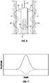
- Centralizers 10 may prevent downhole tool 2 from physically contacting wellbore 4, such as by running into, hitting, and/or rubbing up against wellbore 4. Additionally, centralizers 10 may be used to keep downhole tool 2 properly oriented within wellbore 4. In embodiments, centralizers 10 may produce acoustic noise along wellbore 4. The acoustic noise may comprise of vibrations, wherein, as shown in Figure 6 , the vibrations further comprise a signal wave 18 and/or a plurality of signal waves 18. Signal wave 18 may be recorded by sensors 13 located within sensor cartridges 8. In embodiments, there may be a plurality of centralizers 10. Centralizers 10 may be located at any suitable location along downhole tool 2.
- a suitable location may be about an end of downhole tool 2, about the center, and/or between the center and an end of downhole tool 2.
- a centralizer 10 may be disposed at about opposing ends of downhole tool 2.
- Centralizers 10 may be made of any suitable material. Suitable material may be but is not limited to, stainless steel, titanium, metal, plastic, rubber, neoprene, or any combination thereof.
- acoustic noise created such as from fluid leaking through or behind a casing, flowing fluid channel noise, sand jet entry into a wellbore 4, perforation production, and fluid filtration within a formation.
- Acoustic noise properties may be recorded and analyzed. Specific properties recorded and analyzed may be frequency, amplitude, acoustic mode (compress, shear, etc.), propagation direction, velocity, location azimuthal, and distribution of the noise from a source point.
- This information may be stored on a memory unit 12, as illustrated in Figure 1 , which may provide in tool memory and may comprise flash chips and/or ram chips which may be used to store data and/or buffer data communication.
- Stored data may be transferred to the surface in real-time through wireline 6 to the surface.
- data may be transferred as downhole tool 2 is moving through wellbore 4 and/or while downhole tool 2 is in a fixed position.
- data may be stored on memory unit 12 until downhole tool 2 has been removed from wellbore 4.
- Sensor cartridge 8, as illustrated in Figure 2 may be disposed at any location within downhole tool 2. In embodiments, there may be a plurality of sensor cartridges 8 within downhole tool 2. Sensor cartridge 8 may comprise any type and any number of sensors 13 suitable for detecting acoustic noise. Suitable sensors 13 may include, but are not limited to, monopoles, dipoles, and/or quadrupoles. In embodiments, sensors 13 may be defined as monopole, dipole, and/or quadrupoles based upon the number of sensor surfaces 14 that are connected. Sensor surfaces 14 may be comprised of any suitable material such as piezoceramic material, ferroelectric, lead titanate, lead zirconate, lead metaniobate, or any combination thereof.
- sensor surface 14 includes piezoceramic material. Piezoceramic material may be used to record noise generated within a wellbore 4.
- a dipole sensor 15 may have two sensor surfaces 14 which may be connected. In a dipole configuration, data is recorded from opposite directions and compared against each other.
- a sensor cartridge 8 may have a plurality of different sensors, arranged in any order. The arrangement of sensors may allow for downhole tool 2 to search for defects within wellbore 4 walls.
- sensor 13 may include different sensors such as a monopole sensor 13' and quadrupole sensor 13".
- Figure 4 illustrates a top down view of downhole tool 2 within a wellbore 4.
- Apertures 16 may indicate an area in which a sensor 13 records acoustical sounds.
- downhole tool 2 may comprise two dipole sensors, four monopole sensors, or one dipole and two monopole sensors.
- Each setup may have four sensors 13 set to record acoustic noise in four different directions.
- sensors 13 may comprise six to twelve, eight to ten, six to ten, or eight to twelve sensor surfaces 14.
- Each sensor surface 14 may record within different apertures 16.
- recordings from sensor surface 14 may be combined to produce a larger aperture 17. Larger aperture 17 may be produced using a phased control method.
- Figure 5a illustrates aperture 16 within which a single sensor surface 14 may record and measure acoustic noise.
- Figure 5b illustrates larger aperture 17, which may be created from the combination of three sensor surfaces 14. Larger aperture 17 may allow sensor surface 14 to accurately record and measure in more detail acoustic noise further away.
- a phase control method may be used to create larger aperture 17.
- d may be the distance between different sensors
- k may be the wavenumber
- N may be the number of sensors
- j is an imaginary unit.
- d may be optimized when with the equation below: d ⁇ ⁇ 2 where ⁇ may be the wavelength of signal wave 18.
- downhole tool 2 may move through wellbore 4 at any known velocity, attached to wireline 6.
- Centralizers 10 may keep downhole tool 2 oriented within wellbore 4. Keeping downhole tool 2 properly oriented may include centralizers 10 to remain in about constant contact with the walls of wellbore 4. While in contact with wellbore 4, centralizers 10 may produce "road noise.” Road noise may refer to the acoustical sound of centralizers 10 rubbing against wellbore 4, wireline 6 rubbing against wellbore 4, and/or any noise generated by the continuous movement of downhole tool 2 through wellbore 4. The acoustical sound may produce a signal wave 18. In embodiments, signal wave 18 may be nearly the same at each point centralizers 10 contact wellbore 4 and remain nearly the same as signal wave 18 propagates through the walls in wellbore 4.
- defect signal wave 19 may have a different frequency, amplitude, acoustic mode (compress, shear, etc.), propagation direction, velocity, location azimuthal, and/or distribution of the noise from a source point separate and apart from signal wave 18.
- defect signal wave 19 may also be produced from centralizers 10 coming into contact with a defect.
- Defect signal wave 19 may be recorded by sensors 13. In order to prevent defect single wave 19 from becoming lost in all the data recorded, a method of filtering the signals may be employed to remove road noise from the acoustical noise created by a defect.
- road noise may produce signal wave 18 which may propagate through wellbore 4.
- sensor surfaces 14 may view signal wave 18 within an x and y coordinate system.
- One sensor surface 14 may record signal wave 18 in a positive x and/or y direction, and an opposing sensor surface 14 may record signal wave 18 in a negative x and/or y direction. Therefore, one sensor surface 14 may view signal wave 18 in a negative direction, and an opposing sensor surface 14 may view signal wave 18 in a positive direction.
- signal wave 18 may be nearly identical in properties across wellbore 4
- comparing recorded signal wave 18 from two opposing sensor surfaces 14 may cancel out signal wave 18, removing road noise, through destructive interference.
- a defect signal wave 19 may not be susceptible to destructive interference because there may not be identical defects to produce a defect signal wave 19 with nearly the same signal properties.
- Figure 7 illustrates a graph that may be produced as a sensor 13 records acoustical noise, moving past a defect within wellbore 4.
- sensor 13 may not be able to detect a defect signal wave 19 due to signal dissipation and/or no defects may be present in wellbore 4. Therefore, sensor surface 14 may only record road noise.
- road noise may be nearly identical across wellbore 4, however it is not perfectly identical. Thus, while most road noise may be removed, sensor 13 may still provide data for a plot on a graph signal wave 18 with a reduced amplitude.
- defect signal wave 19 may begin to dissipate, attenuate, and/or not be recorded by sensors 13. This may be graphed as the two separately plotted lines merging back into a singular plotted line comprising mostly of road noise.
- Figure 8a illustrates an embodiment of all recorded acoustical noise, in signal form, as downhole tool 2 moves down and up wellbore 4.
- Filters may separate the data into down-propagation wave results, as illustrated in Figure 8b , and up-propagation wave results, as illustrated in figure 8c .
- a suitable filter may be used such as a frequency wavenumber filter, time space filter, radon filter, median filter, and/or the like.
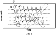
- Each individual line moving along the x-axis may represent the recordings of sensor 13. As illustrated in Figure 9 , these plotted lines may be used to help determine the location of a defect within wellbore 4.
- Individual sensors 13 may be disposed above and below each other, which may detect a defect at different times. Determining the time at which every sensor surface 14 may record a defect signal wave 19 may help filter out any additionally recorded noises which may not have been removed from destructive interference.
- an accelerometer and gyroscope may be positioned within downhole tool 2 to help determine the speed and orientation of downhole tool 2 as it moves throughout wellbore 4. It is to be understood that speed and orientation may be determined by any suitable means. In embodiments, velocity may also be determined by the detection of acoustic noise generated when centralizers 10 come into contact with wellbore collars, not illustrated. Wellbore collars may be devices used to seal joints between two different sections of wellbore 4. The length of these sections may be known and recorded during drilling. Velocity may be determined by using a known length and time to detect acoustic noise generated by different wellbore collars.
- Determining the velocity may allow for the identification of depth and time when a defect at each sensor 13 may be recorded.
- a velocity box 20 may be drawn around defect signal waves 19, which may illustrate the depth and time at which a sensor 13 passed a defect within wellbore 4. This may help in distinguishing between pluralities of defects within wellbore 4.
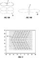
- a synthetic aperture 22 may be produced based off the recorded data from individual sensor surfaces 14. Synthetic aperture 22 may take multiple recordings of sensors 13 at different depths and produce a graph illustrating a single recorded signal wave 18 and/or defect signal wave 19 at any given depth. As illustrated in Figure 10a , a series of apertures 16 may be recorded continuously as downhole tool 2 moves through wellbore 4. The distance between a centralizer 10 and sensor 13 may be known and constant. This may allow for creation of a synthetic aperture 22, illustrated in Figure 10b . As illustrated in Figure 10b , synthetic aperture 22 may combine multiple apertures 16 into a larger synthetic aperture 22. This may increase resolution and depth within the recorded data. A graph, as illustrated in Figure 11 may then be produced from the recorded data.
- Synthetic aperture 22 may combine multiple apertures 16 using a Hilbert transform, wherein the Hilbert transform may calculate the phase shift between different time frames.
- S(t) may be the measurement signal in the time domain.
- the Hilbert transform may be a convolution between time domain signal S(t) and impulse response of the system h(t). Where t is the time index, and ⁇ is the convolution operator.
- aperture 16 measurements at different depth position may be combine together, which may produce a larger measurement area than the original apertures 16.
Landscapes
- Physics & Mathematics (AREA)
- Life Sciences & Earth Sciences (AREA)
- Engineering & Computer Science (AREA)
- Geology (AREA)
- Mining & Mineral Resources (AREA)
- Geophysics (AREA)
- Environmental & Geological Engineering (AREA)
- Fluid Mechanics (AREA)
- General Life Sciences & Earth Sciences (AREA)
- Geochemistry & Mineralogy (AREA)
- Acoustics & Sound (AREA)
- Investigating Or Analyzing Materials By The Use Of Ultrasonic Waves (AREA)
Description
- This invention relates to the field of detecting defects within a wellbore using nondestructive means.
- Oil and gas drilling of a subterranean formation may require a wellbore to facilitate the removal of minerals, fluids, gases, and oils. Running deep below the surface, a wellbore may have to resist high temperatures and pressures exerted upon it from underground formations. Often, defects may form within the wellbore and lead to the loss of minerals, fluids, gases, and oils as they are transported to the surface through the wellbore. Precisely detecting defects within the wellbore may help personnel fix these defects.
- Previous devices and methods that have been used to detect defects within a wellbore may not be able to detect smaller defects within a wellbore. Traditionally used systems include downhole tools which include a mobility platform that is electrically operated to move the downhole tool in the wellbore and an end work device to perform the desired work, as disclosed in
US5947213 .WO2011/051776 discloses apparatus for acoustic measurement in a downhole environment to enable high quality measurements to be obtained in difficult logging conditions.US4303994 discloses measurement systems which detect a downhole drilling variable in relation to the rotational orientation of a drill string during drilling, whereasUS5874676 discloses methods and apparatus for using swept frequency energy to inspect a casing or other body. Additionally, downhole tools used to detect leaks may not transmit data and information to the surface in real-time.US2014/301164 discloses apparatus and systems, which operate to launch acoustic waves along an acoustic path length from an acoustic transducer toward an axis of rotation, to impinge on the front surface of a target substantially fixed with respect to the axis, and to receive a reflection of the acoustic waves from the first front surface at the acoustic transducer. Often, the downhole tools are removed from the wellbore before the data may be analyzed. The analyses of data in real-time may allow personnel to focus on specific areas of the wellbore with a downhole tool, which may provide additional information about the wellbore before removal of the downhole tool. In other examples, previous devices and methods may not have been able to detect azimuthal degrees and/or distance of the defect from the center of the wellbore. The azimuthal degree and distance of the defect from the center of the wellbore may provide information to produce a radial profile of distribution of defects within a wellbore. A radial profile may be used to prevent any leakage or the wellbore and/or may help locate an acoustic noise source produced by a defect. This may prevent the reinsertion of the downhole tool multiple times within the wellbore, saving time and expense. - There is a need for a downhole tool which may be used to detect defects continuously within a wellbore, transmit large amounts of data to the surface in real-time, and increase working efficiency.
- These and other needs in the art may be addressed in embodiments by a device and method comprising a wellbore inspection downhole tool capable of detecting defects in a wellbore. The downhole tool may comprise a wireline, a sensor cartridge wherein the sensor cartridge further comprises at least one sensor, wherein the at least one sensor is a monopole, dipole, or quadrupole, wherein the at least one sensor comprises at least one sensor surface, wherein the at least one sensor surface records acoustic noise within an aperture, wherein two or more sensor surfaces from the at least one sensor surface are combined to produce a larger aperture in which to record the acoustic noise, and a plurality of centralizers. The method for detecting defects within a wellbore may comprise inserting a downhole inspection tool into the wellbore, wherein the downhole inspection tool comprises a wireline, a sensor cartridge wherein the sensor cartridge further comprises at least one sensor, wherein the at least one sensor is a monopole, dipole, or quadrupole, wherein the at least one sensor comprises at least one sensor surface, and a plurality of centralizers. The method further includes producing an acoustic signal with the plurality of centralizers and recording the acoustic signal with the at least one sensor, wherein the sensor records the acoustic signal within an aperture.
- The foregoing has outlined rather broadly the features and technical advantages of the present disclosure in order that the detailed description of the disclosure that follows may be better understood. Additional features and advantages of the disclosure will be described hereinafter that form the subject of the claims of the invention. It should be appreciated by those skilled in the art that the conception and the specific embodiments disclosed may be readily utilized as a basis for modifying or designing other embodiments for carrying out the same purposes of the present invention. It should also be realized by those skilled in the art that such equivalent embodiments do not depart from the scope of the invention as set forth in the appended claims.
- For a detailed description of the preferred embodiments of the invention, reference will now be made to the accompanying drawings in which:
-
Figure 1 illustrates an embodiment of a downhole tool disposed in a wellbore; -
Figure 2 illustrates an embodiment of a sensor cartridge and sensor body; -
Figure 3 illustrates a schematic of a sensor setup; -
Figure 4 illustrates an embodiment of sensors and their aperture areas; -
Figure 5a illustrates an embodiment of a sensor surface and its aperture area; -
Figure 5b illustrates an embodiment of three sensor surfaces combining their aperture area using a phased control; -
Figure 6 illustrates an embodiment of a downhole tool disposed in a wellbore and a signal wave traveling down the wellbore; -
Figure 7 illustrates a graph of sensors recording when passing a defect within a wellbore; -
Figure 8a illustrates a graph of all recorded acoustical noise by a sensor cartridge; -
Figure 8b illustrates a graph of recorded acoustical noise of down-propagation waves; -
Figure 8c illustrates a graph of recorded acoustical noise of the up-propagation waves; -
Figure 9 illustrates a graph of recorded defect signal waves; -
Figure 10a illustrates an embodiment of a downhole tool recording measurements within apertures as to movement through a wellbore; -
Figure 10b illustrates an embodiment of a synthetic aperture; and -
Figure 11 illustrates a graph plotting defect signal waves from a synthetic aperture. - The present disclosure relates to embodiments of a device and method for inspecting a wellbore for defects. More particularly, embodiments of a device and method are disclosed for recording acoustical noise within a wellbore to determine the location of a defect within a wellbore. In embodiments, a downhole tool may be inserted into a wellbore using wireline technology. Within the wellbore, the downhole tool may produce vibrations along the wellbore wall using centralizers disposed on the outside of the downhole tool. Vibrations produced along the wellbore wall may create acoustic noise, which may be recorded by the downhole tool.
- A sensor cartridge within the downhole tool capable of detecting defects in a wellbore may use any combination of sensors in which to detect acoustical noise within the wellbore. Acoustical noise may comprise signal waves which may be accomplished by sensors with a sensor cartridge wherein the sensor cartridge further comprises at least one sensor, wherein the at least one sensor is a monopole, dipole, or quadrupole, wherein the at least one sensor comprises at least one sensor surface, wherein the at least one sensor surface records acoustic noise within an aperture, wherein two or more sensor surfaces from the at least one sensor surface are combined to produce a larger aperture in which to record the acoustic noise. The signal wave data may be recorded, compiled, and analyzed to determine the location of defects within the wellbore wall. Determination of defects, detection of defects and/or transmission of data to the surface may be accomplished in real-time and may be performed as the downhole tool moves through the wellbore. In embodiments, the downhole tool may be removed from the wellbore before the recorded signal wave data may be compiled and analyzed.
- As illustrated in
Figure 1 , adownhole tool 2 may be lowered into awellbore 4 by awireline 6. In other embodiments,downhole tool 2 may be lowered intowellbore 4 by coiled tubing or any other suitable means, not illustrated.Downhole tool 2 may comprise asensor cartridge 8,centralizers 10, andmemory unit 12.Downhole tool 2 may also include any other desired components. In embodiments, there may be a plurality ofsensor cartridges 8 disposed withindownhole tool 2 at any suitable location. In embodiments,downhole tool 2 may be made of any suitable material to resist corrosion and/or deterioration from a fluid or conditions withinwellbore 4. Suitable material may be, but is not limited to, titanium, stainless steel, plastic, and/or any combination thereof.Downhole tool 2 may be any suitable length and width in which to properly house components withindownhole tool 2. A suitable length may be about one foot (approximately 0.30m) to about ten feet (approximately 3.04m), about four feet (approximately 1.22m) to about eight feet (approximately 2.44m), about five feet (approximately 1.52m) to about eight feet (approximately 2.44m), or about three feet (approximately 0.91m) to about six feet (approximately 1.83m). Additionally,downhole tool 2 may have any suitable width. A suitable width may be about one foot (approximately 0.30m) to about three feet (approximately 0.91m), about one inch (approximately 2.54cm) to about three inches (approximately 7.62cm), about three inches (approximately 7.62cm) to about six inches (approximately 15.24cm), about four inches (approximately 10.16cm) to about eight inches (approximately 20.32cm), about six inches (approximately 15.24cm) to about one foot (approximately 0.30m), or about six inches (approximately 15.24cm) to about two feet (approximately 0.51m). -
Centralizers 10 may preventdownhole tool 2 from physically contactingwellbore 4, such as by running into, hitting, and/or rubbing up againstwellbore 4. Additionally, centralizers 10 may be used to keepdownhole tool 2 properly oriented withinwellbore 4. In embodiments,centralizers 10 may produce acoustic noise alongwellbore 4. The acoustic noise may comprise of vibrations, wherein, as shown inFigure 6 , the vibrations further comprise asignal wave 18 and/or a plurality of signal waves 18.Signal wave 18 may be recorded bysensors 13 located withinsensor cartridges 8. In embodiments, there may be a plurality ofcentralizers 10.Centralizers 10 may be located at any suitable location alongdownhole tool 2. A suitable location may be about an end ofdownhole tool 2, about the center, and/or between the center and an end ofdownhole tool 2. In embodiments as illustrated, acentralizer 10 may be disposed at about opposing ends ofdownhole tool 2.Centralizers 10 may be made of any suitable material. Suitable material may be but is not limited to, stainless steel, titanium, metal, plastic, rubber, neoprene, or any combination thereof. - As
downhole tool 2 moves throughwellbore 4, it may record acoustic noise created such as from fluid leaking through or behind a casing, flowing fluid channel noise, sand jet entry into awellbore 4, perforation production, and fluid filtration within a formation. Acoustic noise properties may be recorded and analyzed. Specific properties recorded and analyzed may be frequency, amplitude, acoustic mode (compress, shear, etc.), propagation direction, velocity, location azimuthal, and distribution of the noise from a source point. This information may be stored on amemory unit 12, as illustrated inFigure 1 , which may provide in tool memory and may comprise flash chips and/or ram chips which may be used to store data and/or buffer data communication. Stored data may be transferred to the surface in real-time throughwireline 6 to the surface. In embodiments, data may be transferred asdownhole tool 2 is moving throughwellbore 4 and/or whiledownhole tool 2 is in a fixed position. In embodiments, data may be stored onmemory unit 12 untildownhole tool 2 has been removed fromwellbore 4. -
Sensor cartridge 8, as illustrated inFigure 2 , may be disposed at any location withindownhole tool 2. In embodiments, there may be a plurality ofsensor cartridges 8 withindownhole tool 2.Sensor cartridge 8 may comprise any type and any number ofsensors 13 suitable for detecting acoustic noise.Suitable sensors 13 may include, but are not limited to, monopoles, dipoles, and/or quadrupoles. In embodiments,sensors 13 may be defined as monopole, dipole, and/or quadrupoles based upon the number of sensor surfaces 14 that are connected. Sensor surfaces 14 may be comprised of any suitable material such as piezoceramic material, ferroelectric, lead titanate, lead zirconate, lead metaniobate, or any combination thereof. In embodiments,sensor surface 14 includes piezoceramic material. Piezoceramic material may be used to record noise generated within awellbore 4. As illustrated inFigure 3 , adipole sensor 15 may have twosensor surfaces 14 which may be connected. In a dipole configuration, data is recorded from opposite directions and compared against each other. Referring back toFigure 2 , asensor cartridge 8 may have a plurality of different sensors, arranged in any order. The arrangement of sensors may allow fordownhole tool 2 to search for defects withinwellbore 4 walls. As illustrated inFigure 2 ,sensor 13 may include different sensors such as a monopole sensor 13' andquadrupole sensor 13". -
Figure 4 illustrates a top down view ofdownhole tool 2 within awellbore 4.Apertures 16 may indicate an area in which asensor 13 records acoustical sounds. As illustrated,downhole tool 2 may comprise two dipole sensors, four monopole sensors, or one dipole and two monopole sensors. Each setup may have foursensors 13 set to record acoustic noise in four different directions. In embodiments,sensors 13 may comprise six to twelve, eight to ten, six to ten, or eight to twelve sensor surfaces 14. Eachsensor surface 14 may record withindifferent apertures 16. In embodiments, recordings fromsensor surface 14 may be combined to produce alarger aperture 17.Larger aperture 17 may be produced using a phased control method.Figure 5a illustratesaperture 16 within which asingle sensor surface 14 may record and measure acoustic noise.Figure 5b illustrateslarger aperture 17, which may be created from the combination of three sensor surfaces 14.Larger aperture 17 may allowsensor surface 14 to accurately record and measure in more detail acoustic noise further away. A phase control method may be used to createlarger aperture 17. The phase control equation, as disclosed below:

signal wave 18. - As illustrated in
Figure 6 ,downhole tool 2 may move throughwellbore 4 at any known velocity, attached towireline 6.Centralizers 10 may keepdownhole tool 2 oriented withinwellbore 4. Keepingdownhole tool 2 properly oriented may includecentralizers 10 to remain in about constant contact with the walls ofwellbore 4. While in contact withwellbore 4,centralizers 10 may produce "road noise." Road noise may refer to the acoustical sound ofcentralizers 10 rubbing againstwellbore 4,wireline 6 rubbing againstwellbore 4, and/or any noise generated by the continuous movement ofdownhole tool 2 throughwellbore 4. The acoustical sound may produce asignal wave 18. In embodiments,signal wave 18 may be nearly the same at each point centralizers 10contact wellbore 4 and remain nearly the same assignal wave 18 propagates through the walls inwellbore 4. - As
signal wave 18 propagates throughwellbore 4, it may come into contact with defects withinwellbore 4. These defects may reflect and/or altersignal wave 18, creating adefect signal wave 19. Thedefect signal wave 19 may have a different frequency, amplitude, acoustic mode (compress, shear, etc.), propagation direction, velocity, location azimuthal, and/or distribution of the noise from a source point separate and apart fromsignal wave 18. In embodiments,defect signal wave 19 may also be produced fromcentralizers 10 coming into contact with a defect.Defect signal wave 19 may be recorded bysensors 13. In order to prevent defectsingle wave 19 from becoming lost in all the data recorded, a method of filtering the signals may be employed to remove road noise from the acoustical noise created by a defect. - Referring to
Figure 6 , road noise may producesignal wave 18 which may propagate throughwellbore 4. As illustrated inFigure 4 , sensor surfaces 14 may viewsignal wave 18 within an x and y coordinate system. Onesensor surface 14 may recordsignal wave 18 in a positive x and/or y direction, and an opposingsensor surface 14 may recordsignal wave 18 in a negative x and/or y direction. Therefore, onesensor surface 14 may viewsignal wave 18 in a negative direction, and an opposingsensor surface 14 may viewsignal wave 18 in a positive direction. Thus, becausesignal wave 18 may be nearly identical in properties acrosswellbore 4, comparing recordedsignal wave 18 from two opposing sensor surfaces 14 may cancel outsignal wave 18, removing road noise, through destructive interference. Adefect signal wave 19 may not be susceptible to destructive interference because there may not be identical defects to produce adefect signal wave 19 with nearly the same signal properties. -
Figure 7 illustrates a graph that may be produced as asensor 13 records acoustical noise, moving past a defect withinwellbore 4. Assensor 13 begins moving throughwellbore 4,sensor 13 may not be able to detect adefect signal wave 19 due to signal dissipation and/or no defects may be present inwellbore 4. Therefore,sensor surface 14 may only record road noise. As described above, road noise may be nearly identical acrosswellbore 4, however it is not perfectly identical. Thus, while most road noise may be removed,sensor 13 may still provide data for a plot on agraph signal wave 18 with a reduced amplitude. This may be illustrated as a steady line moving left to right across the illustrated graph inFigure 7 , wherein the y-axis is the height of the amplitude and the x-axis indicates the depth from the surface. Asdownhole tool 2 moves throughwellbore 4,sensor 13 may move past a defect withinwellbore 4.Sensors 13 may then begin to record adefect signal wave 19. At this point, road noise may no longer be produced due to the defect withinwellbore 4. Road noise may begin to dip, moving toward zero, along the y-axis. Thedefect signal wave 19, forming a second line of plotted points, may begin to increase in amplitude and move away from zero along the y-axis. The divergence of these two lines may signal to an operator the location and depth of a defect withinwellbore 4. Assensors 13 move away from the defect, road noise may increase and thedefect signal wave 19 may begin to dissipate, attenuate, and/or not be recorded bysensors 13. This may be graphed as the two separately plotted lines merging back into a singular plotted line comprising mostly of road noise. -
Figure 8a illustrates an embodiment of all recorded acoustical noise, in signal form, asdownhole tool 2 moves down and upwellbore 4. Filters may separate the data into down-propagation wave results, as illustrated inFigure 8b , and up-propagation wave results, as illustrated infigure 8c . A suitable filter may be used such as a frequency wavenumber filter, time space filter, radon filter, median filter, and/or the like. Each individual line moving along the x-axis may represent the recordings ofsensor 13. As illustrated inFigure 9 , these plotted lines may be used to help determine the location of a defect withinwellbore 4.Individual sensors 13 may be disposed above and below each other, which may detect a defect at different times. Determining the time at which everysensor surface 14 may record adefect signal wave 19 may help filter out any additionally recorded noises which may not have been removed from destructive interference. - Within
downhole tool 2, an accelerometer and gyroscope, not illustrated, may be positioned withindownhole tool 2 to help determine the speed and orientation ofdownhole tool 2 as it moves throughoutwellbore 4. It is to be understood that speed and orientation may be determined by any suitable means. In embodiments, velocity may also be determined by the detection of acoustic noise generated whencentralizers 10 come into contact with wellbore collars, not illustrated. Wellbore collars may be devices used to seal joints between two different sections ofwellbore 4. The length of these sections may be known and recorded during drilling. Velocity may be determined by using a known length and time to detect acoustic noise generated by different wellbore collars. Determining the velocity may allow for the identification of depth and time when a defect at eachsensor 13 may be recorded. As illustrated inFigure 9 , avelocity box 20 may be drawn around defect signal waves 19, which may illustrate the depth and time at which asensor 13 passed a defect withinwellbore 4. This may help in distinguishing between pluralities of defects withinwellbore 4. - In embodiments, a
synthetic aperture 22 may be produced based off the recorded data from individual sensor surfaces 14.Synthetic aperture 22 may take multiple recordings ofsensors 13 at different depths and produce a graph illustrating a single recordedsignal wave 18 and/ordefect signal wave 19 at any given depth. As illustrated inFigure 10a , a series ofapertures 16 may be recorded continuously asdownhole tool 2 moves throughwellbore 4. The distance between acentralizer 10 andsensor 13 may be known and constant. This may allow for creation of asynthetic aperture 22, illustrated inFigure 10b . As illustrated inFigure 10b ,synthetic aperture 22 may combinemultiple apertures 16 into a largersynthetic aperture 22. This may increase resolution and depth within the recorded data. A graph, as illustrated inFigure 11 may then be produced from the recorded data. The graph may improve illustration of the location of defects withinwellbore 4.Synthetic aperture 22 may combinemultiple apertures 16 using a Hilbert transform, wherein the Hilbert transform may calculate the phase shift between different time frames. A Hilbert transform is disclosed below:

synthetic aperture 22,aperture 16 measurements at different depth position may be combine together, which may produce a larger measurement area than theoriginal apertures 16. A possible mathematical expression ofsynthetic aperture 22 may be as follows:
synthetic aperture 22 measurements. M1 to MN are theaperture 16 measurements at different positions and depths. Additionally, f() represents the Hilbert transform that is used to shift the phase of each measurement.
Although the present invention and its advantages have been described in detail, it should be understood that various changes, substitutions and alterations may be made herein without departing from the scope of the invention as defined by the appended claims.
Claims (11)
- A wellbore inspection downhole tool (2) capable of detecting defects in a wellbore (4), comprising:a wireline (6);a sensor cartridge (8),a plurality of centralizers (10) producing an acoustic noise, characterized in that the sensor cartridge (10) further comprises at least one sensor (13), wherein the at least one sensor (13) is a monopole, dipole, or quadrupole, wherein the at least one sensor (13) comprises at least one sensor surface (14), wherein the at least one sensor surface (14) records acoustic noise within an aperture (16), wherein two or more sensor surfaces (14) from the at least one sensor surface (14) are combined to produce a larger aperture (17) in which to record the acoustic noise.
- The wellbore inspection downhole tool (2) of claim 1, further comprising a memory unit (12) and an accelerometer.
- The wellbore inspection downhole tool (2) of claim 1, wherein a series of apertures (16) in which the at least one sensor surface (14) records acoustic noise are combined to produce a synthetic aperture (22).
- The wellbore inspection downhole tool (2) of claim 1, further comprising a gyroscope.
- A method for detecting defects within a wellbore (4), comprising:(A) inserting a downhole inspection tool (2) into the wellbore (4), wherein the downhole inspection tool (2) comprises:a wireline (6);a sensor cartridge (8),a plurality of centralizers (10);(B) producing an acoustic signal with the plurality of centralizers (10); and(C) recording the acoustic signal with the at least one sensor (13), wherein the at least one sensor (13) records the acoustic signal within an aperture (16),characterized in that the sensor cartridge (8) further comprises at least one sensor (13), wherein the at least one sensor (13) is a monopole, dipole, or quadrupole, wherein the at least one sensor (13) comprises at least one sensor surface (14), wherein the at least one sensor surface (14) records acoustic noise within an aperture (16), wherein two or more sensor surfaces (14) from the at least one sensor surface (14) are combined to produce a larger aperture (17) in which to record the acoustic noise.
- The method of claim 5, further comprising transmitting the recorded acoustic signals to personnel through the wireline (6) in real-time.
- The method of claim 6, wherein transmitting the recorded acoustic signal Is accomplished when the downhole tool (2) is moving.
- The method of claim 5, further comprising combining apertures (16) into a larger aperture (17), wherein the combination is performed using a phase control.
- The method of claim 5, further comprising combining apertures (16) into a synthetic aperture (22), wherein the combination is performed using a Hilbert transform.
- The method of claim 5, wherein the downhole tool (2) further comprises a memory unit (12).
- The method of claim 5, wherein the downhole tool (2) further comprises an accelerometer and gyroscope.
Applications Claiming Priority (2)
| Application Number | Priority Date | Filing Date | Title |
|---|---|---|---|
| US14/788,112 US9982527B2 (en) | 2015-06-30 | 2015-06-30 | Apparatus and method for a matrix acoustic array |
| PCT/US2016/039341 WO2017003876A1 (en) | 2015-06-30 | 2016-06-24 | Apparatus and method for a matrix acoustic array |
Publications (3)
| Publication Number | Publication Date |
|---|---|
| EP3317699A1 EP3317699A1 (en) | 2018-05-09 |
| EP3317699A4 EP3317699A4 (en) | 2019-03-13 |
| EP3317699B1 true EP3317699B1 (en) | 2020-09-30 |
Family
ID=57608645
Family Applications (1)
| Application Number | Title | Priority Date | Filing Date |
|---|---|---|---|
| EP16818519.7A Not-in-force EP3317699B1 (en) | 2015-06-30 | 2016-06-24 | Apparatus and method for a matrix acoustic array |
Country Status (4)
| Country | Link |
|---|---|
| US (1) | US9982527B2 (en) |
| EP (1) | EP3317699B1 (en) |
| CA (1) | CA2990632A1 (en) |
| WO (1) | WO2017003876A1 (en) |
Families Citing this family (5)
| Publication number | Priority date | Publication date | Assignee | Title |
|---|---|---|---|---|
| US10061050B2 (en) * | 2016-08-08 | 2018-08-28 | Gowell International, Llc | Fractal magnetic sensor array using mega matrix decomposition method for downhole application |
| CN107299833B (en) * | 2017-07-06 | 2020-10-23 | 中国石油大学(北京) | Device and method for detecting leakage of casing |
| US11480706B2 (en) | 2017-10-30 | 2022-10-25 | Baker Hughes Holdings Llc | Multiple casing inspection tool combination with 3D arrays and adaptive dual operational modes |
| US11946364B2 (en) | 2019-10-10 | 2024-04-02 | Halliburton Energy Services, Inc. | Removing guided wave noise from recorded acoustic signals |
| US12098630B2 (en) | 2020-02-04 | 2024-09-24 | Halliburton Energy Services, Inc. | Movement noise suppression in a moving array for downhole leakage localization |
Family Cites Families (34)
| Publication number | Priority date | Publication date | Assignee | Title |
|---|---|---|---|---|
| US3542150A (en) * | 1968-10-10 | 1970-11-24 | Dresser Ind | Acoustic well-logging apparatus having angled acoustic transducers |
| US4303994A (en) | 1979-04-12 | 1981-12-01 | Schlumberger Technology Corporation | System and method for monitoring drill string characteristics during drilling |
| US4641724A (en) * | 1982-07-30 | 1987-02-10 | Schlumberger Technology Corporation | Fracture detection using circumferential offset acoustic paths |
| US4805156A (en) * | 1986-09-22 | 1989-02-14 | Western Atlas International, Inc. | System for acoustically determining the quality of the cement bond in a cased borehole |
| US5146050A (en) * | 1989-04-25 | 1992-09-08 | Western Atlas International, Inc. | Method and apparatus for acoustic formation dip logging |
| FR2646513B1 (en) * | 1989-04-26 | 1991-09-20 | Schlumberger Prospection | LOGGING METHOD AND DEVICE FOR THE ACOUSTIC INSPECTION OF A BORING WITH A TUBING |
| US5213638A (en) | 1990-07-27 | 1993-05-25 | Olin Corporation | Surface modified copper alloys |
| US5092423A (en) * | 1990-12-12 | 1992-03-03 | Atlantic Richfield Company | Downhole seismic array system |
| US5920836A (en) | 1992-11-13 | 1999-07-06 | Dragon Systems, Inc. | Word recognition system using language context at current cursor position to affect recognition probabilities |
| US5852262A (en) * | 1995-09-28 | 1998-12-22 | Magnetic Pulse, Inc. | Acoustic formation logging tool with improved transmitter |
| US5947213A (en) | 1996-12-02 | 1999-09-07 | Intelligent Inspection Corporation | Downhole tools using artificial intelligence based control |
| US5996711A (en) | 1997-04-14 | 1999-12-07 | Schlumberger Technology Corporation | Method and apparatus for locating indexing systems in a cased well and conducting multilateral branch operations |
| US5874676A (en) | 1997-05-12 | 1999-02-23 | Maki, Jr.; Voldi E. | Method and apparatus for acoustically investigating a casing with a swept frequency pulse |
| CA2264409A1 (en) * | 1998-03-16 | 1999-09-16 | Halliburton Energy Services, Inc. | Method for permanent emplacement of sensors inside casing |
| US6510389B1 (en) * | 2000-02-25 | 2003-01-21 | Schlumberger Technology Corporation | Acoustic detection of stress-induced mechanical damage in a borehole wall |
| US6909666B2 (en) * | 2000-11-13 | 2005-06-21 | Baker Hughes Incorporated | Method and apparatus for generating acoustic signals for LWD shear velocity measurement |
| US6541975B2 (en) * | 2001-08-23 | 2003-04-01 | Kjt Enterprises, Inc. | Integrated borehole system for reservoir detection and monitoring |
| US20060062082A1 (en) | 2004-09-23 | 2006-03-23 | Halliburton Energy Services, Inc. | Method and apparatus for generating acoustic signal with single mode of propagation |
| US7133326B2 (en) * | 2004-11-24 | 2006-11-07 | Raytheon Company | Method and system for synthetic aperture sonar |
| US8125848B2 (en) * | 2005-02-22 | 2012-02-28 | Halliburton Energy Services, Inc. | Acoustic logging-while-drilling tools having a hexapole source configuration and associated logging methods |
| US7558153B2 (en) * | 2005-04-19 | 2009-07-07 | Schlumberger Technology Corporation | Radial profiling of slowness: methods and apparatus for near-wellbore alteration estimation |
| US7885142B2 (en) * | 2007-10-02 | 2011-02-08 | Precision Energy Services, Inc. | Method and apparatus for logging foam cement in cased boreholes |
| US7698937B2 (en) * | 2007-10-18 | 2010-04-20 | Neidhardt Deitmar J | Method and apparatus for detecting defects in oilfield tubulars |
| US9477002B2 (en) * | 2007-12-21 | 2016-10-25 | Schlumberger Technology Corporation | Microhydraulic fracturing with downhole acoustic measurement |
| CA2722690C (en) * | 2008-05-08 | 2014-12-09 | Hexion Specialty Chemicals, Inc. | Analysis of radar ranging data from a down hole radar ranging tool for determining width, height, and length of a subterranean fracture |
| BR112012009719B1 (en) * | 2009-10-26 | 2022-05-03 | Prad Research And Development Limited | Devices for acoustic measurement in an in-well environment |
| US9103196B2 (en) * | 2010-08-03 | 2015-08-11 | Baker Hughes Incorporated | Pipelined pulse-echo scheme for an acoustic image tool for use downhole |
| MX2014006393A (en) | 2011-11-30 | 2014-07-22 | Halliburton Energy Serv Inc | Acoustic transducer apparatus, systems, and methods. |
| US9823374B2 (en) | 2013-04-09 | 2017-11-21 | Halliburton Energy Services, Inc. | Methods and apparatus for wellbore evaluation |
| US9567846B2 (en) * | 2014-01-09 | 2017-02-14 | Baker Hughes Incorporated | Devices and methods for downhole acoustic imaging |
| US9772419B2 (en) * | 2014-03-10 | 2017-09-26 | Read As | Decomposing full-waveform sonic data into propagating waves for characterizing a wellbore and its immediate surroundings |
| US8851193B1 (en) * | 2014-04-09 | 2014-10-07 | Cary A. Valerio | Self-centering downhole tool |
| US20160032711A1 (en) * | 2014-07-31 | 2016-02-04 | Schlumberger Technology Corporation | Methods and Apparatus for Measuring Downhole Position and Velocity |
| KR20180094774A (en) * | 2015-03-18 | 2018-08-24 | 디시전 사이선씨즈 메디컬 컴패니, 엘엘씨 | Synthetic aperture ultrasound system |
-
2015
- 2015-06-30 US US14/788,112 patent/US9982527B2/en active Active - Reinstated
-
2016
- 2016-06-24 WO PCT/US2016/039341 patent/WO2017003876A1/en not_active Ceased
- 2016-06-24 CA CA2990632A patent/CA2990632A1/en not_active Abandoned
- 2016-06-24 EP EP16818519.7A patent/EP3317699B1/en not_active Not-in-force
Non-Patent Citations (1)
| Title |
|---|
| None * |
Also Published As
| Publication number | Publication date |
|---|---|
| EP3317699A4 (en) | 2019-03-13 |
| US9982527B2 (en) | 2018-05-29 |
| EP3317699A1 (en) | 2018-05-09 |
| WO2017003876A1 (en) | 2017-01-05 |
| CA2990632A1 (en) | 2017-01-05 |
| US20170002642A1 (en) | 2017-01-05 |
Similar Documents
| Publication | Publication Date | Title |
|---|---|---|
| US9322807B2 (en) | Ultrasonic signal time-frequency decomposition for borehole evaluation or pipeline inspection | |
| US10520626B2 (en) | Continuous beamforming while moving: method to reduce spatial aliasing in leak detection | |
| US11578588B2 (en) | Frequency weighting in broadband acoustic beamforming | |
| US10760410B2 (en) | Stitching methods to enhance beamforming results | |
| EP3132118B1 (en) | Determining locations of acoustic sources around a borehole | |
| EP3488268B1 (en) | Rhodonea cell acoustic hyperlens for thru-casing ultrasonic sensors | |
| EP4048863B1 (en) | Systems and methods for analyzing casing bonding in a well using radial sensing | |
| US11822032B2 (en) | Casing wall thickness detection from higher order shear-horizontal mode signals | |
| US9982527B2 (en) | Apparatus and method for a matrix acoustic array | |
| US9903973B2 (en) | Systems and methods for removing coherent noise in log data | |
| US20160010448A1 (en) | Ultrasonic casing and cement evaluation method using a ray tracing model | |
| EP2682786A2 (en) | Methods and apparatus for determining slowness of wavefronts | |
| US20190145936A1 (en) | Methods and apparatus for acoustic assessment from the interior of fluid conduits | |
| US20160231446A1 (en) | Casing thickness measurement using acoustic wave correlation | |
| US20170205524A1 (en) | Real-time adaptive minimum phase wavelet generation for downhole tools | |
| US20240288404A1 (en) | Annular-a characterization for inner tubular eccentricity and wave propagation speed estimation | |
| US9389330B2 (en) | Formation measurements using flexural modes of guided waves | |
| US20190086572A1 (en) | Apparatus and Method of Quasiperiodic Sequence Acoustic Isolator for Down-Hole Applications | |
| US12410704B2 (en) | Predicting wellbore diameters | |
| US20260110243A1 (en) | Multi-frequency and multi-mode array sonic processing for cement evaluation | |
| BR112022008927B1 (en) | SYSTEM FOR ESTIMATING A PROPERTY OF A REGION OF INTEREST AND METHOD FOR ESTIMATING A PROPERTY OF A REGION OF INTEREST | |
| Sirevaag et al. | Laboratory Setup for Improved Behind Casing |
Legal Events
| Date | Code | Title | Description |
|---|---|---|---|
| STAA | Information on the status of an ep patent application or granted ep patent |
Free format text: STATUS: THE INTERNATIONAL PUBLICATION HAS BEEN MADE |
|
| PUAI | Public reference made under article 153(3) epc to a published international application that has entered the european phase |
Free format text: ORIGINAL CODE: 0009012 |
|
| STAA | Information on the status of an ep patent application or granted ep patent |
Free format text: STATUS: REQUEST FOR EXAMINATION WAS MADE |
|
| 17P | Request for examination filed |
Effective date: 20171123 |
|
| AK | Designated contracting states |
Kind code of ref document: A1 Designated state(s): AL AT BE BG CH CY CZ DE DK EE ES FI FR GB GR HR HU IE IS IT LI LT LU LV MC MK MT NL NO PL PT RO RS SE SI SK SM TR |
|
| AX | Request for extension of the european patent |
Extension state: BA ME |
|
| DAV | Request for validation of the european patent (deleted) | ||
| DAX | Request for extension of the european patent (deleted) | ||
| A4 | Supplementary search report drawn up and despatched |
Effective date: 20190213 |
|
| RIC1 | Information provided on ipc code assigned before grant |
Ipc: G01V 1/40 20060101AFI20190207BHEP Ipc: E21B 47/12 20120101ALI20190207BHEP Ipc: E21B 47/10 20120101ALI20190207BHEP Ipc: E21B 47/00 20120101ALI20190207BHEP Ipc: E21B 47/08 20120101ALI20190207BHEP Ipc: G01V 1/44 20060101ALI20190207BHEP |
|
| GRAP | Despatch of communication of intention to grant a patent |
Free format text: ORIGINAL CODE: EPIDOSNIGR1 |
|
| STAA | Information on the status of an ep patent application or granted ep patent |
Free format text: STATUS: GRANT OF PATENT IS INTENDED |
|
| INTG | Intention to grant announced |
Effective date: 20200325 |
|
| GRAJ | Information related to disapproval of communication of intention to grant by the applicant or resumption of examination proceedings by the epo deleted |
Free format text: ORIGINAL CODE: EPIDOSDIGR1 |
|
| STAA | Information on the status of an ep patent application or granted ep patent |
Free format text: STATUS: REQUEST FOR EXAMINATION WAS MADE |
|
| GRAP | Despatch of communication of intention to grant a patent |
Free format text: ORIGINAL CODE: EPIDOSNIGR1 |
|
| STAA | Information on the status of an ep patent application or granted ep patent |
Free format text: STATUS: GRANT OF PATENT IS INTENDED |
|
| INTC | Intention to grant announced (deleted) | ||
| INTG | Intention to grant announced |
Effective date: 20200619 |
|
| GRAS | Grant fee paid |
Free format text: ORIGINAL CODE: EPIDOSNIGR3 |
|
| GRAA | (expected) grant |
Free format text: ORIGINAL CODE: 0009210 |
|
| STAA | Information on the status of an ep patent application or granted ep patent |
Free format text: STATUS: THE PATENT HAS BEEN GRANTED |
|
| AK | Designated contracting states |
Kind code of ref document: B1 Designated state(s): AL AT BE BG CH CY CZ DE DK EE ES FI FR GB GR HR HU IE IS IT LI LT LU LV MC MK MT NL NO PL PT RO RS SE SI SK SM TR |
|
| REG | Reference to a national code |
Ref country code: CH Ref legal event code: EP Ref country code: GB Ref legal event code: FG4D |
|
| REG | Reference to a national code |
Ref country code: DE Ref legal event code: R096 Ref document number: 602016045097 Country of ref document: DE Ref country code: AT Ref legal event code: REF Ref document number: 1319380 Country of ref document: AT Kind code of ref document: T Effective date: 20201015 |
|
| REG | Reference to a national code |
Ref country code: IE Ref legal event code: FG4D |
|
| RAP2 | Party data changed (patent owner data changed or rights of a patent transferred) |
Owner name: GOWELL INTERNATIONAL, LLC |
|
| PG25 | Lapsed in a contracting state [announced via postgrant information from national office to epo] |
Ref country code: HR Free format text: LAPSE BECAUSE OF FAILURE TO SUBMIT A TRANSLATION OF THE DESCRIPTION OR TO PAY THE FEE WITHIN THE PRESCRIBED TIME-LIMIT Effective date: 20200930 Ref country code: GR Free format text: LAPSE BECAUSE OF FAILURE TO SUBMIT A TRANSLATION OF THE DESCRIPTION OR TO PAY THE FEE WITHIN THE PRESCRIBED TIME-LIMIT Effective date: 20201231 Ref country code: FI Free format text: LAPSE BECAUSE OF FAILURE TO SUBMIT A TRANSLATION OF THE DESCRIPTION OR TO PAY THE FEE WITHIN THE PRESCRIBED TIME-LIMIT Effective date: 20200930 Ref country code: SE Free format text: LAPSE BECAUSE OF FAILURE TO SUBMIT A TRANSLATION OF THE DESCRIPTION OR TO PAY THE FEE WITHIN THE PRESCRIBED TIME-LIMIT Effective date: 20200930 Ref country code: BG Free format text: LAPSE BECAUSE OF FAILURE TO SUBMIT A TRANSLATION OF THE DESCRIPTION OR TO PAY THE FEE WITHIN THE PRESCRIBED TIME-LIMIT Effective date: 20201230 |
|
| REG | Reference to a national code |
Ref country code: NO Ref legal event code: T2 Effective date: 20200930 |
|
| REG | Reference to a national code |
Ref country code: AT Ref legal event code: MK05 Ref document number: 1319380 Country of ref document: AT Kind code of ref document: T Effective date: 20200930 |
|
| PG25 | Lapsed in a contracting state [announced via postgrant information from national office to epo] |
Ref country code: RS Free format text: LAPSE BECAUSE OF FAILURE TO SUBMIT A TRANSLATION OF THE DESCRIPTION OR TO PAY THE FEE WITHIN THE PRESCRIBED TIME-LIMIT Effective date: 20200930 Ref country code: LV Free format text: LAPSE BECAUSE OF FAILURE TO SUBMIT A TRANSLATION OF THE DESCRIPTION OR TO PAY THE FEE WITHIN THE PRESCRIBED TIME-LIMIT Effective date: 20200930 |
|
| REG | Reference to a national code |
Ref country code: NL Ref legal event code: MP Effective date: 20200930 |
|
| REG | Reference to a national code |
Ref country code: LT Ref legal event code: MG4D |
|
| PG25 | Lapsed in a contracting state [announced via postgrant information from national office to epo] |
Ref country code: RO Free format text: LAPSE BECAUSE OF FAILURE TO SUBMIT A TRANSLATION OF THE DESCRIPTION OR TO PAY THE FEE WITHIN THE PRESCRIBED TIME-LIMIT Effective date: 20200930 Ref country code: PT Free format text: LAPSE BECAUSE OF FAILURE TO SUBMIT A TRANSLATION OF THE DESCRIPTION OR TO PAY THE FEE WITHIN THE PRESCRIBED TIME-LIMIT Effective date: 20210201 Ref country code: CZ Free format text: LAPSE BECAUSE OF FAILURE TO SUBMIT A TRANSLATION OF THE DESCRIPTION OR TO PAY THE FEE WITHIN THE PRESCRIBED TIME-LIMIT Effective date: 20200930 Ref country code: LT Free format text: LAPSE BECAUSE OF FAILURE TO SUBMIT A TRANSLATION OF THE DESCRIPTION OR TO PAY THE FEE WITHIN THE PRESCRIBED TIME-LIMIT Effective date: 20200930 Ref country code: EE Free format text: LAPSE BECAUSE OF FAILURE TO SUBMIT A TRANSLATION OF THE DESCRIPTION OR TO PAY THE FEE WITHIN THE PRESCRIBED TIME-LIMIT Effective date: 20200930 Ref country code: SM Free format text: LAPSE BECAUSE OF FAILURE TO SUBMIT A TRANSLATION OF THE DESCRIPTION OR TO PAY THE FEE WITHIN THE PRESCRIBED TIME-LIMIT Effective date: 20200930 |
|
| PG25 | Lapsed in a contracting state [announced via postgrant information from national office to epo] |
Ref country code: PL Free format text: LAPSE BECAUSE OF FAILURE TO SUBMIT A TRANSLATION OF THE DESCRIPTION OR TO PAY THE FEE WITHIN THE PRESCRIBED TIME-LIMIT Effective date: 20200930 Ref country code: IS Free format text: LAPSE BECAUSE OF FAILURE TO SUBMIT A TRANSLATION OF THE DESCRIPTION OR TO PAY THE FEE WITHIN THE PRESCRIBED TIME-LIMIT Effective date: 20210130 Ref country code: AT Free format text: LAPSE BECAUSE OF FAILURE TO SUBMIT A TRANSLATION OF THE DESCRIPTION OR TO PAY THE FEE WITHIN THE PRESCRIBED TIME-LIMIT Effective date: 20200930 Ref country code: AL Free format text: LAPSE BECAUSE OF FAILURE TO SUBMIT A TRANSLATION OF THE DESCRIPTION OR TO PAY THE FEE WITHIN THE PRESCRIBED TIME-LIMIT Effective date: 20200930 Ref country code: ES Free format text: LAPSE BECAUSE OF FAILURE TO SUBMIT A TRANSLATION OF THE DESCRIPTION OR TO PAY THE FEE WITHIN THE PRESCRIBED TIME-LIMIT Effective date: 20200930 |
|
| PG25 | Lapsed in a contracting state [announced via postgrant information from national office to epo] |
Ref country code: NL Free format text: LAPSE BECAUSE OF FAILURE TO SUBMIT A TRANSLATION OF THE DESCRIPTION OR TO PAY THE FEE WITHIN THE PRESCRIBED TIME-LIMIT Effective date: 20200930 Ref country code: SK Free format text: LAPSE BECAUSE OF FAILURE TO SUBMIT A TRANSLATION OF THE DESCRIPTION OR TO PAY THE FEE WITHIN THE PRESCRIBED TIME-LIMIT Effective date: 20200930 |
|
| REG | Reference to a national code |
Ref country code: DE Ref legal event code: R097 Ref document number: 602016045097 Country of ref document: DE |
|
| PLBE | No opposition filed within time limit |
Free format text: ORIGINAL CODE: 0009261 |
|
| STAA | Information on the status of an ep patent application or granted ep patent |
Free format text: STATUS: NO OPPOSITION FILED WITHIN TIME LIMIT |
|
| PG25 | Lapsed in a contracting state [announced via postgrant information from national office to epo] |
Ref country code: DK Free format text: LAPSE BECAUSE OF FAILURE TO SUBMIT A TRANSLATION OF THE DESCRIPTION OR TO PAY THE FEE WITHIN THE PRESCRIBED TIME-LIMIT Effective date: 20200930 |
|
| PGFP | Annual fee paid to national office [announced via postgrant information from national office to epo] |
Ref country code: GB Payment date: 20210623 Year of fee payment: 6 |
|
| 26N | No opposition filed |
Effective date: 20210701 |
|
| PG25 | Lapsed in a contracting state [announced via postgrant information from national office to epo] |
Ref country code: IT Free format text: LAPSE BECAUSE OF FAILURE TO SUBMIT A TRANSLATION OF THE DESCRIPTION OR TO PAY THE FEE WITHIN THE PRESCRIBED TIME-LIMIT Effective date: 20200930 |
|
| PG25 | Lapsed in a contracting state [announced via postgrant information from national office to epo] |
Ref country code: SI Free format text: LAPSE BECAUSE OF FAILURE TO SUBMIT A TRANSLATION OF THE DESCRIPTION OR TO PAY THE FEE WITHIN THE PRESCRIBED TIME-LIMIT Effective date: 20200930 |
|
| PGFP | Annual fee paid to national office [announced via postgrant information from national office to epo] |
Ref country code: NO Payment date: 20210701 Year of fee payment: 6 |
|
| REG | Reference to a national code |
Ref country code: DE Ref legal event code: R119 Ref document number: 602016045097 Country of ref document: DE |
|
| PG25 | Lapsed in a contracting state [announced via postgrant information from national office to epo] |
Ref country code: MC Free format text: LAPSE BECAUSE OF FAILURE TO SUBMIT A TRANSLATION OF THE DESCRIPTION OR TO PAY THE FEE WITHIN THE PRESCRIBED TIME-LIMIT Effective date: 20200930 |
|
| REG | Reference to a national code |
Ref country code: CH Ref legal event code: PL |
|
| REG | Reference to a national code |
Ref country code: BE Ref legal event code: MM Effective date: 20210630 |
|
| PG25 | Lapsed in a contracting state [announced via postgrant information from national office to epo] |
Ref country code: LU Free format text: LAPSE BECAUSE OF NON-PAYMENT OF DUE FEES Effective date: 20210624 |
|
| PG25 | Lapsed in a contracting state [announced via postgrant information from national office to epo] |
Ref country code: LI Free format text: LAPSE BECAUSE OF NON-PAYMENT OF DUE FEES Effective date: 20210630 Ref country code: IE Free format text: LAPSE BECAUSE OF NON-PAYMENT OF DUE FEES Effective date: 20210624 Ref country code: DE Free format text: LAPSE BECAUSE OF NON-PAYMENT OF DUE FEES Effective date: 20220101 Ref country code: CH Free format text: LAPSE BECAUSE OF NON-PAYMENT OF DUE FEES Effective date: 20210630 |
|
| PG25 | Lapsed in a contracting state [announced via postgrant information from national office to epo] |
Ref country code: IS Free format text: LAPSE BECAUSE OF FAILURE TO SUBMIT A TRANSLATION OF THE DESCRIPTION OR TO PAY THE FEE WITHIN THE PRESCRIBED TIME-LIMIT Effective date: 20210130 Ref country code: FR Free format text: LAPSE BECAUSE OF NON-PAYMENT OF DUE FEES Effective date: 20210630 |
|
| PG25 | Lapsed in a contracting state [announced via postgrant information from national office to epo] |
Ref country code: BE Free format text: LAPSE BECAUSE OF NON-PAYMENT OF DUE FEES Effective date: 20210630 |
|
| REG | Reference to a national code |
Ref country code: NO Ref legal event code: MMEP |
|
| GBPC | Gb: european patent ceased through non-payment of renewal fee |
Effective date: 20220624 |
|
| PG25 | Lapsed in a contracting state [announced via postgrant information from national office to epo] |
Ref country code: NO Free format text: LAPSE BECAUSE OF NON-PAYMENT OF DUE FEES Effective date: 20220630 |
|
| PG25 | Lapsed in a contracting state [announced via postgrant information from national office to epo] |
Ref country code: GB Free format text: LAPSE BECAUSE OF NON-PAYMENT OF DUE FEES Effective date: 20220624 |
|
| PG25 | Lapsed in a contracting state [announced via postgrant information from national office to epo] |
Ref country code: CY Free format text: LAPSE BECAUSE OF FAILURE TO SUBMIT A TRANSLATION OF THE DESCRIPTION OR TO PAY THE FEE WITHIN THE PRESCRIBED TIME-LIMIT Effective date: 20200930 |
|
| PG25 | Lapsed in a contracting state [announced via postgrant information from national office to epo] |
Ref country code: HU Free format text: LAPSE BECAUSE OF FAILURE TO SUBMIT A TRANSLATION OF THE DESCRIPTION OR TO PAY THE FEE WITHIN THE PRESCRIBED TIME-LIMIT; INVALID AB INITIO Effective date: 20160624 |
|
| PG25 | Lapsed in a contracting state [announced via postgrant information from national office to epo] |
Ref country code: MK Free format text: LAPSE BECAUSE OF FAILURE TO SUBMIT A TRANSLATION OF THE DESCRIPTION OR TO PAY THE FEE WITHIN THE PRESCRIBED TIME-LIMIT Effective date: 20200930 |
|
| PG25 | Lapsed in a contracting state [announced via postgrant information from national office to epo] |
Ref country code: TR Free format text: LAPSE BECAUSE OF FAILURE TO SUBMIT A TRANSLATION OF THE DESCRIPTION OR TO PAY THE FEE WITHIN THE PRESCRIBED TIME-LIMIT Effective date: 20200930 |
|
| PG25 | Lapsed in a contracting state [announced via postgrant information from national office to epo] |
Ref country code: MT Free format text: LAPSE BECAUSE OF FAILURE TO SUBMIT A TRANSLATION OF THE DESCRIPTION OR TO PAY THE FEE WITHIN THE PRESCRIBED TIME-LIMIT Effective date: 20200930 |