EP3317182B1 - Aircraft passenger seat mechanism - Google Patents
Aircraft passenger seat mechanism Download PDFInfo
- Publication number
- EP3317182B1 EP3317182B1 EP16747548.2A EP16747548A EP3317182B1 EP 3317182 B1 EP3317182 B1 EP 3317182B1 EP 16747548 A EP16747548 A EP 16747548A EP 3317182 B1 EP3317182 B1 EP 3317182B1
- Authority
- EP
- European Patent Office
- Prior art keywords
- seat
- aircraft passenger
- guide track
- passenger seat
- seat back
- Prior art date
- Legal status (The legal status is an assumption and is not a legal conclusion. Google has not performed a legal analysis and makes no representation as to the accuracy of the status listed.)
- Active
Links
Images




Classifications
-
- B—PERFORMING OPERATIONS; TRANSPORTING
- B64—AIRCRAFT; AVIATION; COSMONAUTICS
- B64D—EQUIPMENT FOR FITTING IN OR TO AIRCRAFT; FLIGHT SUITS; PARACHUTES; ARRANGEMENT OR MOUNTING OF POWER PLANTS OR PROPULSION TRANSMISSIONS IN AIRCRAFT
- B64D11/00—Passenger or crew accommodation; Flight-deck installations not otherwise provided for
- B64D11/06—Arrangements of seats, or adaptations or details specially adapted for aircraft seats
- B64D11/0639—Arrangements of seats, or adaptations or details specially adapted for aircraft seats with features for adjustment or converting of seats
- B64D11/064—Adjustable inclination or position of seats
-
- B—PERFORMING OPERATIONS; TRANSPORTING
- B64—AIRCRAFT; AVIATION; COSMONAUTICS
- B64D—EQUIPMENT FOR FITTING IN OR TO AIRCRAFT; FLIGHT SUITS; PARACHUTES; ARRANGEMENT OR MOUNTING OF POWER PLANTS OR PROPULSION TRANSMISSIONS IN AIRCRAFT
- B64D11/00—Passenger or crew accommodation; Flight-deck installations not otherwise provided for
- B64D11/06—Arrangements of seats, or adaptations or details specially adapted for aircraft seats
- B64D11/0639—Arrangements of seats, or adaptations or details specially adapted for aircraft seats with features for adjustment or converting of seats
- B64D11/06395—Arrangements of seats, or adaptations or details specially adapted for aircraft seats with features for adjustment or converting of seats characterised by the arrangement of electric motors for adjustment
-
- B—PERFORMING OPERATIONS; TRANSPORTING
- B64—AIRCRAFT; AVIATION; COSMONAUTICS
- B64D—EQUIPMENT FOR FITTING IN OR TO AIRCRAFT; FLIGHT SUITS; PARACHUTES; ARRANGEMENT OR MOUNTING OF POWER PLANTS OR PROPULSION TRANSMISSIONS IN AIRCRAFT
- B64D11/00—Passenger or crew accommodation; Flight-deck installations not otherwise provided for
- B64D11/06—Arrangements of seats, or adaptations or details specially adapted for aircraft seats
- B64D11/0639—Arrangements of seats, or adaptations or details specially adapted for aircraft seats with features for adjustment or converting of seats
- B64D11/0641—Seats convertible into beds
Definitions
- the present invention relates to an aircraft passenger seat mechanism, particularly but not exclusively for an aircraft sleeper seat convertible into a substantially flat bed.
- An aircraft passenger seat mechanism is disclosed in WO 2007/072045 , comprising a single actuator for driving the seat forwards and backwards, and a cam mechanism and guide track for controlling the angle of the seat back and the seat pan as the seat is driven.
- 'horizontal' and 'vertical' are defined with reference to the floor of the passenger seating area of the aircraft.
- the angle of the floor relative to the gravitational horizontal is determined by the pitch of the aircraft, which is about 15° during take-off and landing, and about 3° in level flight.
- 'forward' and 'rearward' are defined with reference to the direction in which the passenger faces when seated, while in the context of the layout of seats, 'forward' and 'rearward' are defined with reference to the longitudinal direction of the aircraft cabin.
- the lateral direction is defined as being generally horizontal, and perpendicular to the longitudinal direction.
- FIGS 1a to 1d The desired configurations of a seat frame of an aircraft passenger seat are illustrated in Figures 1a to 1d .
- the seat back 3 In the upright configuration shown in Figure 1a , the seat back 3 is at its most upright position, for example being reclined at between 10° and 20°.
- the seat pan 4 is at its most rearward position and is preferably slightly reclined, for example by between 0° and 10°.
- the upright configuration is suitable for sitting upright, for example while the passenger is working or eating.
- the seat pan 4 is at about 10° to the horizontal, while the seat back 3 is between about 15-20° to the vertical.
- the seat back 3 is more reclined and the seat pan 4 has moved forward and is more inclined relative to its position in the upright configuration.
- the angle of reclining of the seat back 3 is about 25-30° to the vertical and the angle of recline of the seat pan 4 is about 15-20° to the horizontal.
- One advantage of this configuration is to avoid tipping the passenger out of the seat 1 during take-off, where the seat 1 faces towards the rear of the aircraft.
- the seat 1 meets the required safety standards for takeoff and landing, such as the 16g test, in this configuration.
- the seat back 3 is reclined by a large angle, such as 40-70°, to the vertical, and the seat pan 4 has moved forward relative to its position in the TTOL configuration.
- the angle of reclining of the seat back 3 and the corresponding forward movement of the seat pan 4 may be varied under control of the passenger, to provide the desired degree of reclining, but the angle of the seat pan 4 remains substantially constant.
- the reclined configuration is suitable for resting and/or in-flight entertainment.
- the seat back 3 and the seat pan 4 are substantially horizontal and form a substantially continuous, flat surface.
- Figure 2 illustrates the upholstery layers provided on the seat frame.
- a padding layer comprising a seat back padding 3b and seat pan padding 4b, are provided on and secured to a seat back frame 3a and seat pan frame 4a respectively.
- a topper layer comprising a seat back topper 3c and a seat pan topper 4c are provided over the seat back padding 3b and seat pan padding 4b respectively.
- the mechanism for reclining the seat 1 is required to move the seat back 3 and the seat pan 4 through a complex path as they pass from the upright to the bed configuration.
- the seat pan 4 is required to move from a slightly rearwardly inclined position (i.e. with the forward end higher than the rearward end) in the upright configuration, to a more rearwardly inclined position in the TTOL and reclined configurations, to a substantially horizontal position in the bed configuration.
- the seat pan 4 first increases and then decreases its inclination as the seat back 3 reclines.
- the top of the seat back 3 moves substantially vertically downwards as the seat back 3 reclines, while the bottom of the seat back 3 moves forwards and remains adjacent to the rearward end of the seat pan 4.
- the seat structure comprises a seat frame 20 slidably mounted on a mounting bracket 21, which is fixed to the cabin floor, for example by attachment to seat rails in the cabin floor.
- Alternative means for fixing the mounting bracket 21 may be used, as described for example in the applicant's patent publication WO 2015/008082 .
- the seat frame 20 is reciprocally driven relative to the mounting bracket 21 in a direction substantially parallel to the cabin floor, for example by a translation actuator (not shown) such an electric motor and a drive mechanism, such as a rack and pinion or other linear drive mechanism.
- the seat pan frame 4a is pivotally attached to the seat frame 20 at a first pivot point PI, towards the front end of the seat pan frame 4a.
- the seat pan frame 4a is pivotally attached to the seat back frame 3a at a second pivot point P2 at or around the rearward end of the seat pan frame 4a and at or around the forward end of the seat back frame 3a.
- the pivotal axes of the first and second pivot points PI, P2 are substantially horizontal and transverse to the seat 1.
- a pinion 24 is attached at or around the lower end of the extension 23.
- the pinion 24 is rotatably driven by a reclining actuator 30, such as an electric motor.
- the reclining actuator 30 may be mounted on the extension 23, with a flexible electrical connection to a power supply in the cabin floor.
- the pinion 24 engages a rack 25 located in or laterally adjacent a cam track or guide track 26, such that the pinion 24 follows the path of the guide track 26 as it is rotatably driven.
- the pinion 24 is mounted on a drive axle 29 coaxially with a roller or bearing 27 that extends through and contacts the guide track 26.
- the bearing 27 is freely rotatable about the drive axle 29 connecting the reclining actuator 30 to the pinion 24, so that the bearing 27 is not rotated by the drive axle 29.
- the bearing 27 is generally circular in cross-section and has an outer diameter substantially equal to the pitch circle diameter of the pinion 24, thus substantially reducing or removing radial load on the pinion 24.
- the rack 25 is located adjacent an upper side of the guide track 26, to avoid dirt or debris collecting between the teeth of the rack 25, but the rack 25 may alternatively be located adjacent a lower side of the guide track 26. In that case, the bearing 27 could be omitted and the rack 25 could be provided along the lower side of the guide track, although this would increase the load on the pinion 24.
- the guide track 26 has a shape that is designed to achieve the seat configurations described above.
- the guide track 26 has a first, generally arcuate section S1 extending downwardly and forwardly from a first end E1, and a second, generally straight section S2 extending upwardly and forwardly from the first section S1 to a second end E2.
- the first and second sections S1, S2 form a continuous spline.
- Alternative shapes may be used, depending on the desired configurations of the seat 1.
- the guide track 26 may be provided in a guide track portion that is removably attached to the seat frame 20. Hence, the shape of the guide track 26 may be changed using different, interchangeable guide track portions, without the need to reconfigure the rest of the seat 1.
- the seat back frame 3a and seat pan frame 4a are reclined further into the reclined configuration, as shown for example in Figures 3 to 5 .
- the seat back frame 3a reclines into contact with a support bar 28, fixed to the seat frame 20 in a position behind the seat back frame 3a.
- the support bar 28 provides support for the seat back frame 3a in the reclined and bed configurations, and therefore prevents excessive force from being applied to the extension arm 23 and thence to the reclining mechanism by the weight of the passenger on the seat back 3.
- the seat back frame 3a is further reclined, in sliding contact with the support bar 28, and the rearward end of the seat pan frame 4a is lifted, into the substantially horizontal bed configuration.
- the pinion 24 may be releasably connected to the reclining actuator 30, for example by a manually actuable clutch, so that the seat 1 may be moved into the TTOL configuration even if the reclining actuator 30 fails, for example on loss of power.
- Alternative linear drive mechanisms to the pinion 24 and rack 25 may be employed, provided that they are able to hold the extension 23 in position and reliably drive the end of the extension 23 along the track 26.
- a roller pinion or friction drive system may be used.
- the reclining mechanism described above is particularly reliable, since the bearing is driven directly along the guide track 26 by the rack 25 and pinion 24, with the driving force applied in the direction of the guide track 26; this tends to reduce the risk of jamming.
- the mechanism improves safety, since it is are located below the seat back and pan frames 3a, 4a and is therefore inaccessible to the seat occupant.
- the reclining mechanism does not occupy space directly under the seat pan frame 4a, thus allowing a footrest or other seat part to be retracted under the seat 1.
- the first and reclining actuators are preferably controlled by a seat control unit (not shown) in coordination so that the seat frame 20 is driven forward by the translation actuator as the seat back frame 3a and seat pan frame 4a are driven by the reclining actuator 30 into the reclined and bed configurations.
- the translation actuator may be controlled independently of the reclining actuator 30, to move the seat 1 forward or back, allowing passengers of different heights to use a footrest comfortably.
Landscapes
- Engineering & Computer Science (AREA)
- Aviation & Aerospace Engineering (AREA)
- Seats For Vehicles (AREA)
- Chairs For Special Purposes, Such As Reclining Chairs (AREA)
Description
- The present invention relates to an aircraft passenger seat mechanism, particularly but not exclusively for an aircraft sleeper seat convertible into a substantially flat bed.
- An aircraft passenger seat mechanism is disclosed in
WO 2007/072045 , comprising a single actuator for driving the seat forwards and backwards, and a cam mechanism and guide track for controlling the angle of the seat back and the seat pan as the seat is driven. - Aspects of the present invention are defined by the accompanying claims.
- Embodiments of the invention will now be described with reference to the drawings identified below.
-
Figures 1a to 1d are schematic side elevations of a seat frame respectively in upright, TTOL, reclining and bed positions. -
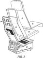
Figure 2 is an exploded diagram of seat upholstery layers applied to the seat frame. -
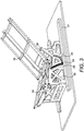
Figure 3 is a perspective view of a seat frame with reclining mechanism, in the reclined position. -
Figure 4 is a side view of the seat frame with reclining mechanism, in the reclined position. -
Figure 5 is a close up view of the mechanism inFigure 4 . -
Figure 6 is a perspective view of a seat frame with reclining mechanism, in the TTOL position. -
Figure 7 is a side view of the seat frame with reclining mechanism, in the TTOL position. -
Figure 8 is a cross-sectional diagram in a lateral vertical plane of a rack, pinion, bearing and guide track in a reclining mechanism in an embodiment. - In this section, 'horizontal' and 'vertical' are defined with reference to the floor of the passenger seating area of the aircraft. As is well-known to the skilled person, the angle of the floor relative to the gravitational horizontal is determined by the pitch of the aircraft, which is about 15° during take-off and landing, and about 3° in level flight. When discussing an individual seat, 'forward' and 'rearward' are defined with reference to the direction in which the passenger faces when seated, while in the context of the layout of seats, 'forward' and 'rearward' are defined with reference to the longitudinal direction of the aircraft cabin. The lateral direction is defined as being generally horizontal, and perpendicular to the longitudinal direction.
- The desired configurations of a seat frame of an aircraft passenger seat are illustrated in
Figures 1a to 1d . In the upright configuration shown inFigure 1a , theseat back 3 is at its most upright position, for example being reclined at between 10° and 20°. Theseat pan 4 is at its most rearward position and is preferably slightly reclined, for example by between 0° and 10°. The upright configuration is suitable for sitting upright, for example while the passenger is working or eating. Theseat pan 4 is at about 10° to the horizontal, while theseat back 3 is between about 15-20° to the vertical. - In the TTOL configuration shown in
Figure 1b , theseat back 3 is more reclined and theseat pan 4 has moved forward and is more inclined relative to its position in the upright configuration. The angle of reclining of theseat back 3 is about 25-30° to the vertical and the angle of recline of theseat pan 4 is about 15-20° to the horizontal. One advantage of this configuration is to avoid tipping the passenger out of the seat 1 during take-off, where the seat 1 faces towards the rear of the aircraft. The seat 1 meets the required safety standards for takeoff and landing, such as the 16g test, in this configuration. - In the reclined configuration as shown in
Figure 1c , theseat back 3 is reclined by a large angle, such as 40-70°, to the vertical, and theseat pan 4 has moved forward relative to its position in the TTOL configuration. The angle of reclining of theseat back 3 and the corresponding forward movement of theseat pan 4 may be varied under control of the passenger, to provide the desired degree of reclining, but the angle of theseat pan 4 remains substantially constant. The reclined configuration is suitable for resting and/or in-flight entertainment. - In the bed configuration as shown in Figure Id, the
seat back 3 and theseat pan 4 are substantially horizontal and form a substantially continuous, flat surface. -
Figure 2 illustrates the upholstery layers provided on the seat frame. A padding layer, comprising a seat back padding 3b and seat pan padding 4b, are provided on and secured to aseat back frame 3a andseat pan frame 4a respectively. A topper layer comprising aseat back topper 3c and aseat pan topper 4c are provided over the seat back padding 3b andseat pan padding 4b respectively. - As described above, the mechanism for reclining the seat 1 is required to move the
seat back 3 and theseat pan 4 through a complex path as they pass from the upright to the bed configuration. In particular, theseat pan 4 is required to move from a slightly rearwardly inclined position (i.e. with the forward end higher than the rearward end) in the upright configuration, to a more rearwardly inclined position in the TTOL and reclined configurations, to a substantially horizontal position in the bed configuration. In other words, theseat pan 4 first increases and then decreases its inclination as the seat back 3 reclines. The top of the seat back 3 moves substantially vertically downwards as the seat back 3 reclines, while the bottom of the seat back 3 moves forwards and remains adjacent to the rearward end of theseat pan 4. These requirements must be met with the least possible weight and sufficient strength to pass the relevant safety standards. - A mechanism for meeting these requirements was disclosed in
WO 2007/072045 , comprising a single actuator for driving the seat forwards and backwards, and a cam mechanism and guide track for controlling the angle of the seat back and the seat pan as the seat is driven. An alternative to that mechanism will now be disclosed, with reference toFigures 3 to 8 ; this mechanism requires separate actuators for reclining and translation, but results in a simpler and more robust mechanism. - In an embodiment of the invention, the seat structure comprises a
seat frame 20 slidably mounted on amounting bracket 21, which is fixed to the cabin floor, for example by attachment to seat rails in the cabin floor. Alternative means for fixing themounting bracket 21 may be used, as described for example in the applicant's patent publicationWO 2015/008082 . Theseat frame 20 is reciprocally driven relative to themounting bracket 21 in a direction substantially parallel to the cabin floor, for example by a translation actuator (not shown) such an electric motor and a drive mechanism, such as a rack and pinion or other linear drive mechanism. - The
seat pan frame 4a is pivotally attached to theseat frame 20 at a first pivot point PI, towards the front end of theseat pan frame 4a. Theseat pan frame 4a is pivotally attached to theseat back frame 3a at a second pivot point P2 at or around the rearward end of theseat pan frame 4a and at or around the forward end of theseat back frame 3a. The pivotal axes of the first and second pivot points PI, P2 are substantially horizontal and transverse to the seat 1. - An extension 23 (for example in the form of an arm as shown in the Figures) is fixed to or integrally formed with the
seat back frame 3a, and extends past the second pivot point P2 from theseat back frame 3a. Hence, theextension 23 andseat back frame 3a form a first order lever about the pivot point P2. - A
pinion 24 is attached at or around the lower end of theextension 23. Thepinion 24 is rotatably driven by a recliningactuator 30, such as an electric motor. The recliningactuator 30 may be mounted on theextension 23, with a flexible electrical connection to a power supply in the cabin floor. Thepinion 24 engages arack 25 located in or laterally adjacent a cam track orguide track 26, such that thepinion 24 follows the path of theguide track 26 as it is rotatably driven. - As shown in
Figure 8 , thepinion 24 is mounted on adrive axle 29 coaxially with a roller or bearing 27 that extends through and contacts theguide track 26. Preferably, thebearing 27 is freely rotatable about thedrive axle 29 connecting the recliningactuator 30 to thepinion 24, so that thebearing 27 is not rotated by thedrive axle 29. Thebearing 27 is generally circular in cross-section and has an outer diameter substantially equal to the pitch circle diameter of thepinion 24, thus substantially reducing or removing radial load on thepinion 24. In this embodiment, therack 25 is located adjacent an upper side of theguide track 26, to avoid dirt or debris collecting between the teeth of therack 25, but therack 25 may alternatively be located adjacent a lower side of theguide track 26. In that case, thebearing 27 could be omitted and therack 25 could be provided along the lower side of the guide track, although this would increase the load on thepinion 24. - The
guide track 26 has a shape that is designed to achieve the seat configurations described above. In this embodiment, theguide track 26 has a first, generally arcuate section S1 extending downwardly and forwardly from a first end E1, and a second, generally straight section S2 extending upwardly and forwardly from the first section S1 to a second end E2. The first and second sections S1, S2 form a continuous spline. Alternative shapes may be used, depending on the desired configurations of the seat 1. Theguide track 26 may be provided in a guide track portion that is removably attached to theseat frame 20. Hence, the shape of theguide track 26 may be changed using different, interchangeable guide track portions, without the need to reconfigure the rest of the seat 1. - When the
pinion 24 is at the first end E1, the seat backframe 3a and the rearward end of theseat pan frame 4a are raised, so that the upright configuration is adopted. As thepinion 24 is driven along therack 25 down theguide track 26, the seat backframe 3a andpan frame 4a are reclined into the TTOL configuration, as shown for example inFigures 6 and7 . - As the
pinion 24 is driven to the junction between the first and second sections S1, S2, the seat backframe 3a andseat pan frame 4a are reclined further into the reclined configuration, as shown for example inFigures 3 to 5 . The seat backframe 3a reclines into contact with asupport bar 28, fixed to theseat frame 20 in a position behind the seat backframe 3a. Thesupport bar 28 provides support for the seat backframe 3a in the reclined and bed configurations, and therefore prevents excessive force from being applied to theextension arm 23 and thence to the reclining mechanism by the weight of the passenger on the seat back 3. - As the
pinion 24 is driven into the second section S2, the seat backframe 3a is further reclined, in sliding contact with thesupport bar 28, and the rearward end of theseat pan frame 4a is lifted, into the substantially horizontal bed configuration. - The
pinion 24 may be releasably connected to thereclining actuator 30, for example by a manually actuable clutch, so that the seat 1 may be moved into the TTOL configuration even if thereclining actuator 30 fails, for example on loss of power. Alternative linear drive mechanisms to thepinion 24 andrack 25 may be employed, provided that they are able to hold theextension 23 in position and reliably drive the end of theextension 23 along thetrack 26. For example, a roller pinion or friction drive system may be used. - The reclining mechanism described above is particularly reliable, since the bearing is driven directly along the
guide track 26 by therack 25 andpinion 24, with the driving force applied in the direction of theguide track 26; this tends to reduce the risk of jamming. The mechanism improves safety, since it is are located below the seat back and panframes seat pan frame 4a, thus allowing a footrest or other seat part to be retracted under the seat 1. - The first and reclining actuators are preferably controlled by a seat control unit (not shown) in coordination so that the
seat frame 20 is driven forward by the translation actuator as the seat backframe 3a andseat pan frame 4a are driven by the recliningactuator 30 into the reclined and bed configurations. When the seat 1 is in the upright or TTOL configurations, the translation actuator may be controlled independently of thereclining actuator 30, to move the seat 1 forward or back, allowing passengers of different heights to use a footrest comfortably. - The above embodiments illustrate, but do not limit, the present invention. Alternative embodiments which may occur to the skilled reader on reading the above description may also fall within the scope of the invention as defined by the accompanying claims.
Claims (15)
- An aircraft passenger seat comprising a seat back (3) and a seat pan (4), the seat pan (4) being pivotally connected at or around a forward end thereof to a seat frame (20) at a first pivot point (PI), and at or around a rearward end thereof to a lower end of the seat back (3) at a second pivot point (P2); the seat back (3) having an extension (23) extending beyond the second pivot point (P2) and engaging a guide track (26) in or connected to the seat frame (20), and a reclining actuator (30) for driving the extension (23) along the guide track (26) so as to adjust the reclining of the seat; characterised in that the extension (23) is driven by a linear drive mechanism (24, 25) aligned with the guide track (26).
- The aircraft passenger seat of claim 1, wherein the linear drive mechanism comprises a pinion (24) driven by the reclining actuator and engaging a rack (25) arranged along the guide track (26).
- The aircraft passenger seat of claim 2, wherein the rack (25) is arranged along an upper side (26) of the guide track.
- The aircraft passenger seat of any one of claims 1 to 3, including a clutch for releasing the linear drive mechanism (24, 25) from the reclining actuator (30).
- The aircraft passenger seat of any preceding claim, wherein the extension (23) carries a bearing (27) moveable along the guide track (26), the bearing (27) being arranged to reduce loading on the linear drive mechanism (24, 25).
- The aircraft passenger seat of any preceding claim, wherein the guide track (26) is located in the seat frame (20), below the lower end of the seat back (3).
- The aircraft passenger seat of any preceding claim, wherein the guide track (26) has a first section (S1) extending downwardly and forwardly from a first end (E1), such that the seat back (3) reclines as the extension (23) is driven along the first section (S1) away from the first end (E1),
and optionally wherein the first section (S1) is arcuate. - The aircraft passenger seat of any preceding claim, wherein the guide track (26) has a second section (S2) extending upwardly and forwardly towards a second end (E2), such that the seat back (3) reclines and the rearward end of the seat pan (4) is raised as the extension (23) is driven along the second section (S2) towards the second end (E2),
and optionally wherein the second section (S2) is substantially straight. - The aircraft passenger seat of any preceding claim, wherein the guide track (26) is removably attached to the seat frame (20).
- The aircraft passenger seat of any preceding claim, including a support (28) attached to the seat frame (20) and arranged to support the seat back (3) in a reclined position; and optionally wherein the support (28) is arranged to slide against the seat back (3) as the seat back (3) reclines.
- The aircraft passenger seat of any preceding claim, wherein the seat frame (20) is slidably supported on a mounting bracket (21) for fixing the seat to a cabin floor.
- The aircraft passenger seat of claim 11, including a translation actuator for driving the seat frame relative to the mounting bracket.
- The aircraft passenger seat of claim 11 or claim 12, including a seat controller for controlling the reclining actuator and the translation actuator.
- The aircraft passenger seat of claim 13, wherein the seat controller is arranged to move the seat forward as the seat back is reclined.
- The aircraft passenger seat of claim 13 or claim 14, wherein the seat controller is arranged to move the seat forward when the seat back is upright, independently of movement of the reclining actuator.
Applications Claiming Priority (2)
| Application Number | Priority Date | Filing Date | Title |
|---|---|---|---|
| GB1511467.1A GB2539913B (en) | 2015-06-30 | 2015-06-30 | Aircraft passenger seat mechanism |
| PCT/GB2016/051948 WO2017001845A1 (en) | 2015-06-30 | 2016-06-29 | Aircraft passenger seat mechanism |
Publications (3)
| Publication Number | Publication Date |
|---|---|
| EP3317182A1 EP3317182A1 (en) | 2018-05-09 |
| EP3317182B1 true EP3317182B1 (en) | 2019-09-04 |
| EP3317182B8 EP3317182B8 (en) | 2019-10-09 |
Family
ID=53872449
Family Applications (1)
| Application Number | Title | Priority Date | Filing Date |
|---|---|---|---|
| EP16747548.2A Active EP3317182B8 (en) | 2015-06-30 | 2016-06-29 | Aircraft passenger seat mechanism |
Country Status (4)
| Country | Link |
|---|---|
| US (1) | US10450071B2 (en) |
| EP (1) | EP3317182B8 (en) |
| GB (1) | GB2539913B (en) |
| WO (1) | WO2017001845A1 (en) |
Families Citing this family (18)
| Publication number | Priority date | Publication date | Assignee | Title |
|---|---|---|---|---|
| CA2985893A1 (en) * | 2015-05-14 | 2016-11-17 | VIP Cinema LLC | Dual motion sloped floor recline mechanism for a theater |
| GB2560996B (en) * | 2017-03-31 | 2021-04-14 | Ipeco Holdings Ltd | Seating apparatus |
| US10596926B2 (en) | 2017-07-26 | 2020-03-24 | Textron Innovations, Inc. | Seat tracking system |
| US10464679B2 (en) * | 2017-08-22 | 2019-11-05 | Ami Industries, Inc. | Stowable seat with pivoting seat pan for advanced comfort |
| US10829222B2 (en) * | 2017-11-20 | 2020-11-10 | B/E Aerospace, Inc. | Aircraft passenger seat with zero-g taxi, take-off and landing recline position |
| CA3036019C (en) * | 2018-03-06 | 2026-04-28 | Bombardier Inc. | Passenger seat for aircraft |
| EP3543123A1 (en) * | 2018-03-23 | 2019-09-25 | Adient Aerospace LLC | A seat for an aircraft |
| GB2586143B (en) | 2019-08-07 | 2022-12-28 | Safran Seats Gb Ltd | Aircraft Seat and Mechanism for seat actuation |
| US11447252B2 (en) * | 2019-10-01 | 2022-09-20 | B/E Aerospace, Inc. | Aircraft seat with separated seat back and seat pan |
| US11767905B2 (en) * | 2020-08-07 | 2023-09-26 | Ami Industries, Inc. | Laminated rack assembly for powered motion of aircraft seats |
| US12414884B1 (en) * | 2021-06-04 | 2025-09-16 | Ki Mobility, LLC | Tiltable wheelchair |
| US11401038B1 (en) | 2021-06-07 | 2022-08-02 | B/E Aerospace, Inc. | Aircraft seat |
| DE102021127103A1 (en) | 2021-10-19 | 2023-04-20 | Bayerische Motoren Werke Aktiengesellschaft | Motor vehicle seat for a motor vehicle |
| GB2619724A (en) | 2022-06-13 | 2023-12-20 | Dca Design International Ltd | Aircraft seat mechanism |
| GB2630598A (en) * | 2023-05-31 | 2024-12-04 | Alice Blu Aero Ltd | Seat mechanism |
| US12630291B2 (en) | 2024-02-08 | 2026-05-19 | B/E Aerospace, Inc. | Aircraft seat base tracking system |
| EP4603387A1 (en) * | 2024-02-14 | 2025-08-20 | Airbus Operations GmbH | Universal aircraft passenger seat platform and system, and method of installing an aircraft passenger seat system |
| WO2026013041A1 (en) | 2024-07-08 | 2026-01-15 | Novamont S.P.A. | Improved process for the synthesis and purification of hmf |
Family Cites Families (44)
| Publication number | Priority date | Publication date | Assignee | Title |
|---|---|---|---|---|
| AU3636778A (en) * | 1977-05-27 | 1979-11-29 | Ettridge J P | Children's reclining car seats |
| DE2916897A1 (en) * | 1979-04-07 | 1980-11-06 | Otto Zapf | Adjustable vehicle seat with reclining position - has hinged seat and back supports attached to plates sliding over base frame |
| US4364603A (en) * | 1979-11-02 | 1982-12-21 | Pontiac Furniture, Inc. | Reclining chair |
| US4504090A (en) * | 1982-10-20 | 1985-03-12 | Goldman Paul R | Swivel, tilt and recline arm chair |
| SE449164B (en) | 1984-03-12 | 1987-04-13 | Henning Bergenwall | MOBILE INCLUDING A STAND, ONE SEAT AND RELATIVELY SET SWINGABLE SEAT |
| US4877291A (en) * | 1987-12-14 | 1989-10-31 | Taylor William P | Reclining chair |
| US5108148A (en) * | 1990-09-07 | 1992-04-28 | Henke Franz J | Reclining chair mechanism having sole support pivot |
| GB9425078D0 (en) * | 1994-12-13 | 1995-02-08 | British Airways Plc | A seating unit |
| DE19756272C1 (en) * | 1997-12-18 | 1999-07-15 | Faure Bertrand Sitztech Gmbh | Seat for motor vehicle |
| US6030043A (en) * | 1997-12-18 | 2000-02-29 | Bertrand Faure Sitztechnik Gmbh & Co. Kg | Motor vehicle seat, in particular back seat |
| NO313933B1 (en) * | 1999-03-01 | 2002-12-30 | Kjartan Alvestad | Adjustment device for reclining or seating furniture |
| IT1306152B1 (en) * | 1999-06-02 | 2001-05-30 | Aviointeriors Spa | ARMCHAIR WITH PERFECTED CRADLE MOVEMENT, IN PARTICULAR AIRCRAFT. |
| GB9918263D0 (en) * | 1999-08-04 | 1999-10-06 | Britax Rumbold Ltd | Seating unit of a passenger vehicle |
| AU1042301A (en) | 1999-11-04 | 2001-05-14 | Reynard Aviation Ltd. | Improvements in and relating to seats for passenger vehicles |
| US6305644B1 (en) * | 1999-11-10 | 2001-10-23 | B E Aerospace, Inc. | Aircraft cabin seat configuration with enhanced ingress/egress |
| DE10019484A1 (en) * | 2000-04-19 | 2001-10-31 | Recaro Aircraft Seating Gmbh | Vehicle seat, in particular passenger seat |
| US6742840B2 (en) * | 2001-05-25 | 2004-06-01 | Weber Aircraft Lp | Adjustable seats |
| US6692069B2 (en) * | 2001-07-20 | 2004-02-17 | B E Aerospace, Inc. | Aircraft sleeper seat |
| ATE514593T1 (en) * | 2001-08-09 | 2011-07-15 | Virgin Atlantic Airways Ltd | A SEAT UNIT FOR A VEHICLE |
| JP2006123715A (en) * | 2004-10-28 | 2006-05-18 | Nhk Spring Co Ltd | Vehicle seat |
| GB0517384D0 (en) * | 2005-08-26 | 2005-10-05 | Birkbeck Hilary R | Variable configuration seating |
| ATE474772T1 (en) * | 2005-12-23 | 2010-08-15 | British Airways Plc | AIRCRAFT PASSENGER SEAT |
| GB2442438A (en) | 2006-10-06 | 2008-04-09 | Dominic James Robinson | Adjustable seat with load cell and counterbalance |
| JP5220319B2 (en) * | 2007-01-18 | 2013-06-26 | 日本発條株式会社 | Vehicle seat device |
| GB0704546D0 (en) * | 2007-03-08 | 2007-04-18 | Contour Premium Aircraft Seati | Adjustable seat |
| GB0706775D0 (en) * | 2007-04-05 | 2007-05-16 | Premium Aircraft Interiors Uk | Aircraft seat |
| JP5179798B2 (en) * | 2007-05-22 | 2013-04-10 | 株式会社デルタツーリング | Seat structure |
| EP2313316B1 (en) * | 2008-08-05 | 2012-05-09 | BE Aerospace, Inc. | Seat articulation mechanism |
| JP5396978B2 (en) * | 2009-04-10 | 2014-01-22 | トヨタ紡織株式会社 | Vehicle seat |
| US8376458B2 (en) * | 2009-11-02 | 2013-02-19 | B/E Aerospace, Inc. | Seat pan cam follower with drop down mechanism |
| WO2011100476A1 (en) * | 2010-02-10 | 2011-08-18 | Weber Aircraft Llc | Passenger seat |
| US8827365B2 (en) * | 2010-02-10 | 2014-09-09 | Zodiac Seats Us Llc | Passenger seat |
| US8403415B2 (en) * | 2010-08-16 | 2013-03-26 | Be Aerospace, Inc. | Aircraft passenger seat recline mechanism |
| US8579375B2 (en) * | 2010-12-01 | 2013-11-12 | Zodiac Seats France | Aircraft seat |
| US9266613B2 (en) | 2011-05-27 | 2016-02-23 | Robert J. Henshaw | Seating arrangement |
| US8733840B2 (en) * | 2011-07-06 | 2014-05-27 | Zodiac Seats Us Llc | Seat pan assembly |
| US9073453B2 (en) * | 2011-10-07 | 2015-07-07 | Bombardier Inc. | Aircraft seat |
| US9061766B2 (en) * | 2011-11-30 | 2015-06-23 | Burkley U. Kladde | Synchronous seat recline mechanism |
| US9227729B2 (en) * | 2013-04-08 | 2016-01-05 | B/E Aerospace, Inc. | Aircraft seat employing dual actuators for seat translaton and seat recline |
| WO2014168916A1 (en) * | 2013-04-08 | 2014-10-16 | B/E Aerospace, Inc. | Aircraft seat with translating seatback linkage pivot |
| GB2516433B (en) | 2013-07-19 | 2016-02-17 | British Airways Plc | Aircraft passenger seat fixing system |
| CN105683042B (en) * | 2013-10-21 | 2017-12-08 | B/E航空公司 | Independence for aircraft seat is hinged seat plate |
| CN106414240B (en) * | 2014-04-02 | 2020-12-29 | Be航天公司 | Bracket tilt mechanism for aircraft seats with fixed shells |
| US20170021930A1 (en) * | 2014-04-02 | 2017-01-26 | B/E Aerospace, Inc. | Cradle recline mechanism for aircraft passenger seat |
-
2015
- 2015-06-30 GB GB1511467.1A patent/GB2539913B/en not_active Expired - Fee Related
-
2016
- 2016-06-29 US US15/741,040 patent/US10450071B2/en not_active Expired - Fee Related
- 2016-06-29 WO PCT/GB2016/051948 patent/WO2017001845A1/en not_active Ceased
- 2016-06-29 EP EP16747548.2A patent/EP3317182B8/en active Active
Non-Patent Citations (1)
| Title |
|---|
| None * |
Also Published As
| Publication number | Publication date |
|---|---|
| WO2017001845A1 (en) | 2017-01-05 |
| GB201511467D0 (en) | 2015-08-12 |
| US20180194474A1 (en) | 2018-07-12 |
| GB2539913A (en) | 2017-01-04 |
| GB2539913B (en) | 2019-10-02 |
| US10450071B2 (en) | 2019-10-22 |
| EP3317182B8 (en) | 2019-10-09 |
| EP3317182A1 (en) | 2018-05-09 |
Similar Documents
| Publication | Publication Date | Title |
|---|---|---|
| US10450071B2 (en) | Aircraft passenger seat mechanism | |
| EP2414233B1 (en) | Passenger seat with single actuator seat mechanism | |
| EP2983944B1 (en) | Aircraft seat employing dual actuators for seat translation and seat recline | |
| EP2983563B1 (en) | Vehicle seat with simultaneous articulation of seat pan and seat back | |
| EP3519243B1 (en) | Aircraft passenger seat assembly including a backrest tilt apparatus | |
| US8419123B2 (en) | Aircraft seat | |
| EP2212150B1 (en) | Convertible aircraft passenger seat and method | |
| EP3231706A1 (en) | Aircraft passenger seat recline mechanism | |
| US9738388B2 (en) | Aircraft seat with occupant weight sensing mechanism to adjust tilt-recline force | |
| EP2646319A1 (en) | Aircraft seat | |
| EP1097864A1 (en) | Improvements in and relating to seats for passenger vehicles | |
| US6808234B2 (en) | Seat | |
| GB2630598A (en) | Seat mechanism |
Legal Events
| Date | Code | Title | Description |
|---|---|---|---|
| STAA | Information on the status of an ep patent application or granted ep patent |
Free format text: STATUS: THE INTERNATIONAL PUBLICATION HAS BEEN MADE |
|
| PUAI | Public reference made under article 153(3) epc to a published international application that has entered the european phase |
Free format text: ORIGINAL CODE: 0009012 |
|
| STAA | Information on the status of an ep patent application or granted ep patent |
Free format text: STATUS: REQUEST FOR EXAMINATION WAS MADE |
|
| 17P | Request for examination filed |
Effective date: 20180115 |
|
| AK | Designated contracting states |
Kind code of ref document: A1 Designated state(s): AL AT BE BG CH CY CZ DE DK EE ES FI FR GB GR HR HU IE IS IT LI LT LU LV MC MK MT NL NO PL PT RO RS SE SI SK SM TR |
|
| AX | Request for extension of the european patent |
Extension state: BA ME |
|
| DAV | Request for validation of the european patent (deleted) | ||
| DAX | Request for extension of the european patent (deleted) | ||
| GRAJ | Information related to disapproval of communication of intention to grant by the applicant or resumption of examination proceedings by the epo deleted |
Free format text: ORIGINAL CODE: EPIDOSDIGR1 |
|
| STAA | Information on the status of an ep patent application or granted ep patent |
Free format text: STATUS: GRANT OF PATENT IS INTENDED |
|
| GRAP | Despatch of communication of intention to grant a patent |
Free format text: ORIGINAL CODE: EPIDOSNIGR1 |
|
| INTG | Intention to grant announced |
Effective date: 20190212 |
|
| GRAS | Grant fee paid |
Free format text: ORIGINAL CODE: EPIDOSNIGR3 |
|
| GRAJ | Information related to disapproval of communication of intention to grant by the applicant or resumption of examination proceedings by the epo deleted |
Free format text: ORIGINAL CODE: EPIDOSDIGR1 |
|
| GRAL | Information related to payment of fee for publishing/printing deleted |
Free format text: ORIGINAL CODE: EPIDOSDIGR3 |
|
| STAA | Information on the status of an ep patent application or granted ep patent |
Free format text: STATUS: REQUEST FOR EXAMINATION WAS MADE |
|
| GRAR | Information related to intention to grant a patent recorded |
Free format text: ORIGINAL CODE: EPIDOSNIGR71 |
|
| STAA | Information on the status of an ep patent application or granted ep patent |
Free format text: STATUS: GRANT OF PATENT IS INTENDED |
|
| GRAA | (expected) grant |
Free format text: ORIGINAL CODE: 0009210 |
|
| STAA | Information on the status of an ep patent application or granted ep patent |
Free format text: STATUS: THE PATENT HAS BEEN GRANTED |
|
| INTC | Intention to grant announced (deleted) | ||
| AK | Designated contracting states |
Kind code of ref document: B1 Designated state(s): AL AT BE BG CH CY CZ DE DK EE ES FI FR GB GR HR HU IE IS IT LI LT LU LV MC MK MT NL NO PL PT RO RS SE SI SK SM TR |
|
| INTG | Intention to grant announced |
Effective date: 20190730 |
|
| REG | Reference to a national code |
Ref country code: GB Ref legal event code: FG4D |
|
| REG | Reference to a national code |
Ref country code: CH Ref legal event code: EP Ref country code: CH Ref legal event code: PK Free format text: BERICHTIGUNG B8 |
|
| REG | Reference to a national code |
Ref country code: AT Ref legal event code: REF Ref document number: 1174991 Country of ref document: AT Kind code of ref document: T Effective date: 20190915 |
|
| RBV | Designated contracting states (corrected) |
Designated state(s): AL AT BE BG CH CY CZ DE DK EE ES FI FR GR HR HU IE IS IT LI LT LU LV MC MK MT NL NO PL PT RO RS SE SI SK SM TR |
|
| REG | Reference to a national code |
Ref country code: DE Ref legal event code: R096 Ref document number: 602016019996 Country of ref document: DE |
|
| REG | Reference to a national code |
Ref country code: IE Ref legal event code: FG4D |
|
| REG | Reference to a national code |
Ref country code: NL Ref legal event code: MP Effective date: 20190904 |
|
| REG | Reference to a national code |
Ref country code: LT Ref legal event code: MG4D |
|
| PG25 | Lapsed in a contracting state [announced via postgrant information from national office to epo] |
Ref country code: FI Free format text: LAPSE BECAUSE OF FAILURE TO SUBMIT A TRANSLATION OF THE DESCRIPTION OR TO PAY THE FEE WITHIN THE PRESCRIBED TIME-LIMIT Effective date: 20190904 Ref country code: HR Free format text: LAPSE BECAUSE OF FAILURE TO SUBMIT A TRANSLATION OF THE DESCRIPTION OR TO PAY THE FEE WITHIN THE PRESCRIBED TIME-LIMIT Effective date: 20190904 Ref country code: SE Free format text: LAPSE BECAUSE OF FAILURE TO SUBMIT A TRANSLATION OF THE DESCRIPTION OR TO PAY THE FEE WITHIN THE PRESCRIBED TIME-LIMIT Effective date: 20190904 Ref country code: BG Free format text: LAPSE BECAUSE OF FAILURE TO SUBMIT A TRANSLATION OF THE DESCRIPTION OR TO PAY THE FEE WITHIN THE PRESCRIBED TIME-LIMIT Effective date: 20191204 Ref country code: LT Free format text: LAPSE BECAUSE OF FAILURE TO SUBMIT A TRANSLATION OF THE DESCRIPTION OR TO PAY THE FEE WITHIN THE PRESCRIBED TIME-LIMIT Effective date: 20190904 Ref country code: NO Free format text: LAPSE BECAUSE OF FAILURE TO SUBMIT A TRANSLATION OF THE DESCRIPTION OR TO PAY THE FEE WITHIN THE PRESCRIBED TIME-LIMIT Effective date: 20191204 |
|
| PG25 | Lapsed in a contracting state [announced via postgrant information from national office to epo] |
Ref country code: ES Free format text: LAPSE BECAUSE OF FAILURE TO SUBMIT A TRANSLATION OF THE DESCRIPTION OR TO PAY THE FEE WITHIN THE PRESCRIBED TIME-LIMIT Effective date: 20190904 Ref country code: LV Free format text: LAPSE BECAUSE OF FAILURE TO SUBMIT A TRANSLATION OF THE DESCRIPTION OR TO PAY THE FEE WITHIN THE PRESCRIBED TIME-LIMIT Effective date: 20190904 Ref country code: AL Free format text: LAPSE BECAUSE OF FAILURE TO SUBMIT A TRANSLATION OF THE DESCRIPTION OR TO PAY THE FEE WITHIN THE PRESCRIBED TIME-LIMIT Effective date: 20190904 Ref country code: GR Free format text: LAPSE BECAUSE OF FAILURE TO SUBMIT A TRANSLATION OF THE DESCRIPTION OR TO PAY THE FEE WITHIN THE PRESCRIBED TIME-LIMIT Effective date: 20191205 Ref country code: RS Free format text: LAPSE BECAUSE OF FAILURE TO SUBMIT A TRANSLATION OF THE DESCRIPTION OR TO PAY THE FEE WITHIN THE PRESCRIBED TIME-LIMIT Effective date: 20190904 |
|
| REG | Reference to a national code |
Ref country code: AT Ref legal event code: MK05 Ref document number: 1174991 Country of ref document: AT Kind code of ref document: T Effective date: 20190904 |
|
| PG25 | Lapsed in a contracting state [announced via postgrant information from national office to epo] |
Ref country code: IT Free format text: LAPSE BECAUSE OF FAILURE TO SUBMIT A TRANSLATION OF THE DESCRIPTION OR TO PAY THE FEE WITHIN THE PRESCRIBED TIME-LIMIT Effective date: 20190904 Ref country code: EE Free format text: LAPSE BECAUSE OF FAILURE TO SUBMIT A TRANSLATION OF THE DESCRIPTION OR TO PAY THE FEE WITHIN THE PRESCRIBED TIME-LIMIT Effective date: 20190904 Ref country code: PL Free format text: LAPSE BECAUSE OF FAILURE TO SUBMIT A TRANSLATION OF THE DESCRIPTION OR TO PAY THE FEE WITHIN THE PRESCRIBED TIME-LIMIT Effective date: 20190904 Ref country code: PT Free format text: LAPSE BECAUSE OF FAILURE TO SUBMIT A TRANSLATION OF THE DESCRIPTION OR TO PAY THE FEE WITHIN THE PRESCRIBED TIME-LIMIT Effective date: 20200106 Ref country code: NL Free format text: LAPSE BECAUSE OF FAILURE TO SUBMIT A TRANSLATION OF THE DESCRIPTION OR TO PAY THE FEE WITHIN THE PRESCRIBED TIME-LIMIT Effective date: 20190904 Ref country code: RO Free format text: LAPSE BECAUSE OF FAILURE TO SUBMIT A TRANSLATION OF THE DESCRIPTION OR TO PAY THE FEE WITHIN THE PRESCRIBED TIME-LIMIT Effective date: 20190904 Ref country code: AT Free format text: LAPSE BECAUSE OF FAILURE TO SUBMIT A TRANSLATION OF THE DESCRIPTION OR TO PAY THE FEE WITHIN THE PRESCRIBED TIME-LIMIT Effective date: 20190904 |
|
| PG25 | Lapsed in a contracting state [announced via postgrant information from national office to epo] |
Ref country code: CZ Free format text: LAPSE BECAUSE OF FAILURE TO SUBMIT A TRANSLATION OF THE DESCRIPTION OR TO PAY THE FEE WITHIN THE PRESCRIBED TIME-LIMIT Effective date: 20190904 Ref country code: SK Free format text: LAPSE BECAUSE OF FAILURE TO SUBMIT A TRANSLATION OF THE DESCRIPTION OR TO PAY THE FEE WITHIN THE PRESCRIBED TIME-LIMIT Effective date: 20190904 Ref country code: SM Free format text: LAPSE BECAUSE OF FAILURE TO SUBMIT A TRANSLATION OF THE DESCRIPTION OR TO PAY THE FEE WITHIN THE PRESCRIBED TIME-LIMIT Effective date: 20190904 Ref country code: IS Free format text: LAPSE BECAUSE OF FAILURE TO SUBMIT A TRANSLATION OF THE DESCRIPTION OR TO PAY THE FEE WITHIN THE PRESCRIBED TIME-LIMIT Effective date: 20200224 |
|
| REG | Reference to a national code |
Ref country code: DE Ref legal event code: R097 Ref document number: 602016019996 Country of ref document: DE |
|
| PLBE | No opposition filed within time limit |
Free format text: ORIGINAL CODE: 0009261 |
|
| STAA | Information on the status of an ep patent application or granted ep patent |
Free format text: STATUS: NO OPPOSITION FILED WITHIN TIME LIMIT |
|
| PG2D | Information on lapse in contracting state deleted |
Ref country code: IS |
|
| PG25 | Lapsed in a contracting state [announced via postgrant information from national office to epo] |
Ref country code: DK Free format text: LAPSE BECAUSE OF FAILURE TO SUBMIT A TRANSLATION OF THE DESCRIPTION OR TO PAY THE FEE WITHIN THE PRESCRIBED TIME-LIMIT Effective date: 20190904 Ref country code: IS Free format text: LAPSE BECAUSE OF FAILURE TO SUBMIT A TRANSLATION OF THE DESCRIPTION OR TO PAY THE FEE WITHIN THE PRESCRIBED TIME-LIMIT Effective date: 20200105 |
|
| 26N | No opposition filed |
Effective date: 20200605 |
|
| PG25 | Lapsed in a contracting state [announced via postgrant information from national office to epo] |
Ref country code: SI Free format text: LAPSE BECAUSE OF FAILURE TO SUBMIT A TRANSLATION OF THE DESCRIPTION OR TO PAY THE FEE WITHIN THE PRESCRIBED TIME-LIMIT Effective date: 20190904 |
|
| REG | Reference to a national code |
Ref country code: DE Ref legal event code: R119 Ref document number: 602016019996 Country of ref document: DE |
|
| PG25 | Lapsed in a contracting state [announced via postgrant information from national office to epo] |
Ref country code: MC Free format text: LAPSE BECAUSE OF FAILURE TO SUBMIT A TRANSLATION OF THE DESCRIPTION OR TO PAY THE FEE WITHIN THE PRESCRIBED TIME-LIMIT Effective date: 20190904 |
|
| REG | Reference to a national code |
Ref country code: CH Ref legal event code: PL |
|
| PG25 | Lapsed in a contracting state [announced via postgrant information from national office to epo] |
Ref country code: LU Free format text: LAPSE BECAUSE OF NON-PAYMENT OF DUE FEES Effective date: 20200629 |
|
| REG | Reference to a national code |
Ref country code: BE Ref legal event code: MM Effective date: 20200630 |
|
| PG25 | Lapsed in a contracting state [announced via postgrant information from national office to epo] |
Ref country code: LI Free format text: LAPSE BECAUSE OF NON-PAYMENT OF DUE FEES Effective date: 20200630 Ref country code: CH Free format text: LAPSE BECAUSE OF NON-PAYMENT OF DUE FEES Effective date: 20200630 Ref country code: IE Free format text: LAPSE BECAUSE OF NON-PAYMENT OF DUE FEES Effective date: 20200629 Ref country code: FR Free format text: LAPSE BECAUSE OF NON-PAYMENT OF DUE FEES Effective date: 20200630 |
|
| PG25 | Lapsed in a contracting state [announced via postgrant information from national office to epo] |
Ref country code: BE Free format text: LAPSE BECAUSE OF NON-PAYMENT OF DUE FEES Effective date: 20200630 Ref country code: DE Free format text: LAPSE BECAUSE OF NON-PAYMENT OF DUE FEES Effective date: 20210101 |
|
| PG25 | Lapsed in a contracting state [announced via postgrant information from national office to epo] |
Ref country code: TR Free format text: LAPSE BECAUSE OF FAILURE TO SUBMIT A TRANSLATION OF THE DESCRIPTION OR TO PAY THE FEE WITHIN THE PRESCRIBED TIME-LIMIT Effective date: 20190904 Ref country code: MT Free format text: LAPSE BECAUSE OF FAILURE TO SUBMIT A TRANSLATION OF THE DESCRIPTION OR TO PAY THE FEE WITHIN THE PRESCRIBED TIME-LIMIT Effective date: 20190904 Ref country code: CY Free format text: LAPSE BECAUSE OF FAILURE TO SUBMIT A TRANSLATION OF THE DESCRIPTION OR TO PAY THE FEE WITHIN THE PRESCRIBED TIME-LIMIT Effective date: 20190904 |
|
| PG25 | Lapsed in a contracting state [announced via postgrant information from national office to epo] |
Ref country code: MK Free format text: LAPSE BECAUSE OF FAILURE TO SUBMIT A TRANSLATION OF THE DESCRIPTION OR TO PAY THE FEE WITHIN THE PRESCRIBED TIME-LIMIT Effective date: 20190904 |