EP3316669B1 - Integrated card rail and cooling module for embedded computing systems - Google Patents
Integrated card rail and cooling module for embedded computing systems Download PDFInfo
- Publication number
- EP3316669B1 EP3316669B1 EP17199475.9A EP17199475A EP3316669B1 EP 3316669 B1 EP3316669 B1 EP 3316669B1 EP 17199475 A EP17199475 A EP 17199475A EP 3316669 B1 EP3316669 B1 EP 3316669B1
- Authority
- EP
- European Patent Office
- Prior art keywords
- card
- flow
- cooling
- rail
- base plate
- Prior art date
- Legal status (The legal status is an assumption and is not a legal conclusion. Google has not performed a legal analysis and makes no representation as to the accuracy of the status listed.)
- Not-in-force
Links
Images




Classifications
-
- H—ELECTRICITY
- H05—ELECTRIC TECHNIQUES NOT OTHERWISE PROVIDED FOR
- H05K—PRINTED CIRCUITS; CASINGS OR CONSTRUCTIONAL DETAILS OF ELECTRIC APPARATUS; MANUFACTURE OF ASSEMBLAGES OF ELECTRICAL COMPONENTS
- H05K7/00—Constructional details common to different types of electric apparatus
- H05K7/20—Modifications to facilitate cooling, ventilating, or heating
- H05K7/20218—Modifications to facilitate cooling, ventilating, or heating using a liquid coolant without phase change in electronic enclosures
- H05K7/20272—Accessories for moving fluid, for expanding fluid, for connecting fluid conduits, for distributing fluid, for removing gas or for preventing leakage, e.g. pumps, tanks or manifolds
-
- H—ELECTRICITY
- H05—ELECTRIC TECHNIQUES NOT OTHERWISE PROVIDED FOR
- H05K—PRINTED CIRCUITS; CASINGS OR CONSTRUCTIONAL DETAILS OF ELECTRIC APPARATUS; MANUFACTURE OF ASSEMBLAGES OF ELECTRICAL COMPONENTS
- H05K7/00—Constructional details common to different types of electric apparatus
- H05K7/20—Modifications to facilitate cooling, ventilating, or heating
- H05K7/20536—Modifications to facilitate cooling, ventilating, or heating for racks or cabinets of standardised dimensions, e.g. electronic racks for aircraft or telecommunication equipment
- H05K7/20627—Liquid coolant without phase change
- H05K7/20636—Liquid coolant without phase change within sub-racks for removing heat from electronic boards
-
- H—ELECTRICITY
- H05—ELECTRIC TECHNIQUES NOT OTHERWISE PROVIDED FOR
- H05K—PRINTED CIRCUITS; CASINGS OR CONSTRUCTIONAL DETAILS OF ELECTRIC APPARATUS; MANUFACTURE OF ASSEMBLAGES OF ELECTRICAL COMPONENTS
- H05K7/00—Constructional details common to different types of electric apparatus
- H05K7/14—Mounting supporting structure in casing or on frame or rack
- H05K7/1417—Mounting supporting structure in casing or on frame or rack having securing means for mounting boards, plates or wiring boards
- H05K7/1418—Card guides, e.g. grooves
-
- H—ELECTRICITY
- H05—ELECTRIC TECHNIQUES NOT OTHERWISE PROVIDED FOR
- H05K—PRINTED CIRCUITS; CASINGS OR CONSTRUCTIONAL DETAILS OF ELECTRIC APPARATUS; MANUFACTURE OF ASSEMBLAGES OF ELECTRICAL COMPONENTS
- H05K7/00—Constructional details common to different types of electric apparatus
- H05K7/14—Mounting supporting structure in casing or on frame or rack
- H05K7/1422—Printed circuit boards receptacles, e.g. stacked structures, electronic circuit modules or box like frames
-
- H—ELECTRICITY
- H05—ELECTRIC TECHNIQUES NOT OTHERWISE PROVIDED FOR
- H05K—PRINTED CIRCUITS; CASINGS OR CONSTRUCTIONAL DETAILS OF ELECTRIC APPARATUS; MANUFACTURE OF ASSEMBLAGES OF ELECTRICAL COMPONENTS
- H05K7/00—Constructional details common to different types of electric apparatus
- H05K7/14—Mounting supporting structure in casing or on frame or rack
- H05K7/1422—Printed circuit boards receptacles, e.g. stacked structures, electronic circuit modules or box like frames
- H05K7/1424—Card cages
-
- H—ELECTRICITY
- H05—ELECTRIC TECHNIQUES NOT OTHERWISE PROVIDED FOR
- H05K—PRINTED CIRCUITS; CASINGS OR CONSTRUCTIONAL DETAILS OF ELECTRIC APPARATUS; MANUFACTURE OF ASSEMBLAGES OF ELECTRICAL COMPONENTS
- H05K7/00—Constructional details common to different types of electric apparatus
- H05K7/14—Mounting supporting structure in casing or on frame or rack
- H05K7/1422—Printed circuit boards receptacles, e.g. stacked structures, electronic circuit modules or box like frames
- H05K7/1424—Card cages
- H05K7/1425—Card cages of standardised dimensions, e.g. 19"-subrack
-
- H—ELECTRICITY
- H05—ELECTRIC TECHNIQUES NOT OTHERWISE PROVIDED FOR
- H05K—PRINTED CIRCUITS; CASINGS OR CONSTRUCTIONAL DETAILS OF ELECTRIC APPARATUS; MANUFACTURE OF ASSEMBLAGES OF ELECTRICAL COMPONENTS
- H05K7/00—Constructional details common to different types of electric apparatus
- H05K7/20—Modifications to facilitate cooling, ventilating, or heating
-
- H—ELECTRICITY
- H05—ELECTRIC TECHNIQUES NOT OTHERWISE PROVIDED FOR
- H05K—PRINTED CIRCUITS; CASINGS OR CONSTRUCTIONAL DETAILS OF ELECTRIC APPARATUS; MANUFACTURE OF ASSEMBLAGES OF ELECTRICAL COMPONENTS
- H05K7/00—Constructional details common to different types of electric apparatus
- H05K7/20—Modifications to facilitate cooling, ventilating, or heating
- H05K7/20009—Modifications to facilitate cooling, ventilating, or heating using a gaseous coolant in electronic enclosures
- H05K7/20136—Forced ventilation, e.g. by fans
- H05K7/20145—Means for directing air flow, e.g. ducts, deflectors, plenum or guides
-
- H—ELECTRICITY
- H05—ELECTRIC TECHNIQUES NOT OTHERWISE PROVIDED FOR
- H05K—PRINTED CIRCUITS; CASINGS OR CONSTRUCTIONAL DETAILS OF ELECTRIC APPARATUS; MANUFACTURE OF ASSEMBLAGES OF ELECTRICAL COMPONENTS
- H05K7/00—Constructional details common to different types of electric apparatus
- H05K7/20—Modifications to facilitate cooling, ventilating, or heating
- H05K7/20218—Modifications to facilitate cooling, ventilating, or heating using a liquid coolant without phase change in electronic enclosures
-
- H—ELECTRICITY
- H05—ELECTRIC TECHNIQUES NOT OTHERWISE PROVIDED FOR
- H05K—PRINTED CIRCUITS; CASINGS OR CONSTRUCTIONAL DETAILS OF ELECTRIC APPARATUS; MANUFACTURE OF ASSEMBLAGES OF ELECTRICAL COMPONENTS
- H05K7/00—Constructional details common to different types of electric apparatus
- H05K7/20—Modifications to facilitate cooling, ventilating, or heating
- H05K7/20536—Modifications to facilitate cooling, ventilating, or heating for racks or cabinets of standardised dimensions, e.g. electronic racks for aircraft or telecommunication equipment
- H05K7/20627—Liquid coolant without phase change
- H05K7/20645—Liquid coolant without phase change within cabinets for removing heat from sub-racks
-
- H—ELECTRICITY
- H05—ELECTRIC TECHNIQUES NOT OTHERWISE PROVIDED FOR
- H05K—PRINTED CIRCUITS; CASINGS OR CONSTRUCTIONAL DETAILS OF ELECTRIC APPARATUS; MANUFACTURE OF ASSEMBLAGES OF ELECTRICAL COMPONENTS
- H05K7/00—Constructional details common to different types of electric apparatus
- H05K7/20—Modifications to facilitate cooling, ventilating, or heating
- H05K7/20536—Modifications to facilitate cooling, ventilating, or heating for racks or cabinets of standardised dimensions, e.g. electronic racks for aircraft or telecommunication equipment
- H05K7/20663—Liquid coolant with phase change, e.g. heat pipes
- H05K7/20672—Liquid coolant with phase change, e.g. heat pipes within sub-racks for removing heat from electronic boards
Definitions
- Embodiments of the subject matter described herein relate generally to a circuit card rail module for a circuit module chassis assembly and, more particularly, to an integrated card rail and cooling module.
- a circuit module chassis assembly is typically used to mount industry standard circuit cards for various electronic applications, such as embedded computing systems.
- the circuit module chassis assembly may include a chassis supporting one or more rail modules for mechanically securing and electrically interconnecting the circuit cards and a power supply.
- Such circuit module chassis assemblies may be equipped with different circuit cards for various applications including but not limited to embedded computing systems for defense, military and aircraft applications.
- the circuit cards used in these applications and platforms typically include powered integrated circuits and other electronic components that generate significant heat which must be dissipated during operation.
- Such cooling has traditionally been accomplished by conducting heat away from the electronics through the circuit board and/or rail structure, then dissipating heat from the rail structure through natural or forced convection. In some instances, cooling air may be directed to impinge directly on the components and/or circuit card.
- circuit module chassis assemblies are incorporating additional cooling functions for removing heat generated by the electronics and more precisely maintaining the circuit cards within a given temperature range.
- These chassis assemblies may employ flow-through technology, in addition to the traditional methods of cooling, where a cooling fluid, in the form of a gas or a liquid, is directed through the structure of the chassis assembly to draw heat away from the electronics.
- VITA the trade association responsible for setting standard computing architectures serving the embedded computing systems industry, is developing a new air flow through (AFT) cooling standard, VITA 48.8, for use in size, weight, power and cost (SWAP-C) constrained 3U and 6U VPX module-based systems.
- AFT air flow through
- SWAP-C size, weight, power and cost
- EP 30 38 151 A1 describes a cold plate for cooling heat generating components comprising two plates extending parallel to one another and a core sandwiched between the two plates.
- US 2015/000871 A1 describes a housing with heat pipes integrated into enclosure fins thereof.
- US 2008/218980 A1 describes a method and system for dissipating thermal energy from conduction-cooled circuit card assemblies which employ remote heat sinks and heat pipes.
- US 2011/267776 A1 describes a conduction-cooled apparatus and methods of forming said apparatus.
- US 2008/007913 A1 describes a card cage for holding a set of electronic cards with a set of walls having an input for receiving a fluid and a set of flow paths formed therein.
- US 2015/305198 A1 describes a monolithic multi-module electronics chassis with multi-planar embedded fluid cooling channels.
- a flow-through card rail which includes a base plate defining a first major face and a second major face opposite the first major face.
- An elongated guide rail is formed on the first major face and extends from a first end of the base plate toward a second end opposite the first end.
- the elongated guide rail defines a card channel configured to receive a circuit card.
- a corrugated structure is formed on the second major face and includes a plurality of elongated cells extending from the first end toward the second end of the base plate.
- Each elongated cell has a cooling passage formed therein which extends from a fluid inlet to a fluid outlet.
- the flow-through card rail is configured to receive a cooling fluid at the fluid inlet, direct the cooling fluid through the cooling passages, and exhaust the cooling fluid at the fluid outlet.
- a flow-through card rail which includes a base plate defining a first major face and a second major face opposite the first major face.
- An end wall is formed on a first end of the base plate.
- a pair of side walls are formed on the sides of the base plate and extend from the first end and terminate at a marginal region of the base plate.
- a plurality of guide rails are formed on the first major face and extend from the first end to the marginal region of the base plate.
- Each guide rail has a cooling passage formed therein which extends from a fluid inlet formed through the end wall to a fluid outlet. Adjacent guide rails define a card channel therebetween that is configured to receive a circuit card.
- a corrugated structure is formed on the second major face and includes an outer face having a plurality of ridges and furrows and a plurality of elongated cells.
- Each elongated cell has a cooling passage formed therein which extends from the fluid inlet to the fluid outlet.
- the flow-through card rail is configured to receive a cooling fluid at the fluid inlet, direct the cooling fluid through the cooling passages, and exhaust the cooling fluid at the fluid outlet.
- a chassis assembly supports a card rail module and includes a pair of flow-through card rails that are arranged in a spaced facing relationship and configured to support a circuit card therebetween.
- a power supply is electrically coupled to the card rail module and configured to power the circuit card.
- a cooling system operates to draw a cooling fluid through the card rail module.
- Each card rail is configured as a flow-through card rail for receiving cooling fluid from the cooling system at a fluid inlet, directing cooling fluid through cooling passages, and exhausting cooling fluid through a fluid outlet.
- a base plate defines a first major face and a second major face opposite the first major face.
- a plurality of elongated guide rails are formed on the first major face and extend from a first end of the base plate toward a second end opposite the first end. Adjacent elongated guide rails define a card channel therebetween for receiving a circuit card.
- a corrugated structure is formed on the second major face and includes a plurality of elongated cells extending from the first end toward the second end of the base plate. Each elongated cell has a cooling passage which extends from a fluid inlet in communication with the cooling system to a fluid outlet.
- Embodiments of the subject matter described herein generally relate to an integrated card rail and cooling module.
- several integrated card rail and cooling modules are arranged in a chassis assembly with circuit cards to provide a flow-through cooling function for an embedded computing system.
- an embedded computing system 10 includes a chassis assembly 12 supporting two flow-through card rails 14, 16 arranged in a spaced facing relationship and configured to receive a plurality of circuit cards 18. As shown in FIG. 1 , the chassis assembly 12 is configured to support two sets of flow-through card rails 14, 16, each set holding six circuit cards 18.
- the number and location of the flow-through card rails and circuit cards supported in the chassis assembly 12 may be adapted based on the specification and functionality of the embedded computing system 10.
- the integrated rail and cooling module further detailed below may be adapted for other unique applications requiring enhanced cooling functionality in a lightweight, compact card chassis.
- the chassis assembly 12 includes a housing 20 enclosing a power supply 22 and chassis electronics 24 electrically coupled to the flow-through card rails 14, 16 for powering, controlling, communicating, monitoring and interfacing with the circuit cards 18. Interfaces 26, 28 may provide communication with external electronic components and/or electrical power to the embedded computing system 10.
- the chassis assembly 12 also includes a cooling system 32 operable for drawing a cooling fluid through the chassis assembly 12 and the flow-through card rails 14, 16 to affect cooling of the electronics mounted on the circuit cards 18 within the embedded computing system 10.
- the cooling system 32 includes a fan or pump 34 for drawing the cooling fluid into a manifold 36 having a plenum 38 and supply ducts 40 in fluid communication with the flow-through card rails 14, 16 as further detailed herein.
- the cooling system 32 may also include a heat exchanger 42 for conditioning the cooling fluid in the manifold 36.
- the heat exchanger 42 may take the form of a simple radiator or a more complex vapor-compression heat exchanger system.
- the cooling system 32 may also include a controller 44 configured to receive data concerning the thermal state of the components of the embedded computing system 10 and control operation of the cooling system 32 in response thereto. Such control may include operation of the fan or pump 34 and/or control of supply valves 46 disposed in the supply ducts 40.
- Card rail 100 includes a planer base plate 102 framed by a pair of side walls 104, 106 and an end wall 108 extending generally perpendicular to the base plate 102.
- the end wall 108 is formed at a first end of the base plate 102 and defines an inlet end of the card rail 100.
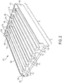
- a plurality of elongated guide rails 110 are formed on a first major face 112 of the base plate 102 and extend from the end wall 108 toward a second end of the base plate 102.
- the elongated guide rails 110 are arranged in a spaced relationship on the first major face 112, which in combination with the side walls 104, 106 define a plurality of card channels 114.
- Each card channel 114 is configured to securely receive a circuit card 18 in a conventional manner.
- a buttress 116 formed on a top surface 118 of each elongated guide rail 110 against the end wall 108 and provides a boss for mounting a backplane that supports the circuit cards 18.
- the elongated guide rails 110 terminate before the second end of the base plate 102 to define a marginal region 120 thereon.
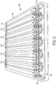
- a corrugated structure 122 is formed on a second major face 124 of the base plate 102 opposite the first major face 112.
- the corrugated structure 122 includes a plurality of elongated cells 126, which define ridges 132 and furrows 134 on an outer face of the corrugated structure 122.
- the surface area of the corrugated structure 122 is significantly greater than the surface area of the second major face 124.
- the elongated cells 126 are arranged on the opposite side of the base plate 102 from the first major face 112 and laterally offset with respect to the guide rails 110 formed thereon.
- card rail 100 is configured to provide a flow-through cooling function.
- cooling passages 128, 130 are formed through the elongated guide rails 110 and the elongated cells 126, respectively.
- the cooling passages 128,130 extend through the end wall 108 to define a fluid inlet in the card rail 100 as best shown in FIG 4 .
- the cooling passages 128 extending through the elongated guide rails 110 pass from the first major face 112 through the second major face 124 of the base plate and terminate at the marginal region 120 to define a fluid outlet in the card rail 100.
- the cooling passages 130 extend through the elongated cells 126 and terminate at the marginal region 120 of the second major face 124 to further define the fluid outlet in the card rail 100.
- the cooling passages 128, 130 may be subdivided by internal walls 136, 138 to form a grouping of smaller channels that define a honeycombed cross-section140.
- the internal walls 136 provides sufficient internal support such that the elongated guide rails 110 adequately support the circuit cards 18; whereas the internal walls 138 provide such that the corrugated structure 122 may be load bearing.
- the card rails 100 may be integrated into the chassis assembly 12 as a portion of the housing 20 for the embedded computing system 10 shown in FIG. 1 .
- the internal walls 136 subdivide the cooling passages 130 in the elongated cells 126 and are arranged in an alternating pattern.
- the specific configuration of the internal walls 136 may be adapted based on the specifications and functional requirements of a given application such that honeycombed cross-section may have a different cross-sectional geometry than specifically illustrated in the figures.
- the term honeycomb refers to a grouping of small channels regardless of the particular cross-section.
- the effective cross-sectional area of the cooling passages 128 may be configured to maintain a particular pressure drop across the card rail 100 and/or a particular flow rate through the card rail 100.
- the effective cross-sectional area of the cooling passages 128,130 as well as the surface area of the corrugated structure 122 may be configured to provide a card rail capable of dissipating the thermal load from the circuit cards 18 to maintain a target rail temperature, for example an 85° C rail temperature.
- the card rail 100 is formed as a one-piece or monolithic component from a single material.
- the card rail 100 may be fabricated using a direct metal laser sintering process using a structurally strong, highly-conductive material.
- the card rail 100 may be formed from an Al-Si-Mg or Ti powdered metal alloy.
- the card rail 100 has a consistent thermal conductivity throughout, and thus eliminates thermal resistance boundaries and air gaps that would otherwise exist at the interface of disparate materials or components.
- a middle portion M of the card rail 100 is formed as a one-piece or monolithic component and the inlet portion I and an outlet portion O of the card rail 100 are formed as separate components that are joined to the middle portion M.
- the middle portion M may be extruded using a structurally strong, highly-conductive material.
- the inlet and outlet portions I, O are then mated to the middle portion M in a mechanically joined manner with fasteners or the like, or in a materially joined manner by bonding, welding, brazing or the like.
- FIG. 1 schematically illustrates the side wall of the card rails as being fluidly coupled to the supply ducts 40 of the manifold 36, however in practice the manifold 36 is fluidly coupled to the cooling passages 128, 130 formed in the card rail 100.
- the end wall 108 of the card rail 100 is fluidly coupled to the manifold 36 such that the inlet end of the card rail 100 is in fluid communication with the manifold 36.
- the card rail 100 is arranged in the chassis assembly 12 such that cooling fluid is exhausted from outlet end the card rail 100 out of the chassis assembly 12 into the ambient environment surrounding the embedded computing system 10.
- cooling fluid is drawn through the chassis assembly 12 by the fan 34 into the plenum 38.
- the cooling fluid may optionally be conditioned by the heat exchanger 42.
- the cooling fluid is then directed through the supply ducts 40 into the cooling passages 128, 130 formed in card rails 14, 16, 100.
- the cooling system 32 is configured to create a pressure differential that forces the cooling fluid through the card rail from the manifold 36 to the marginal region 120 of the base plate 102.
- the fluid inlet is defined adjacent the end wall 108 and the fluid outlet is defined adjacent the marginal region 120.
- the cooling system 32 may be configured to create a pressure differential that draws the cooling fluid through the card rail 100 from the marginal region 120 to the end wall 108.
- the fluid inlet is defined adjacent the marginal region 120 and the fluid outlet is defined adjacent to the end wall 108.
- the terms "inlet” and "outlet” are relative to the fluid flow direction and should not be limited to a specific structure or location in the described embodiments.
- the configuration of the cooling passages 128, 130 through the elongated guide rails 110 and elongated cells 126 provides direct cooling where needed.
- heat generated by components of the embedded computing system is conducted from the circuit cards 18 to the card rail 100 and through elongated guide rails 110 and the corrugated structure 122.
- heat is dissipated from the card rail 100 by forced convection.
- Heat is also dissipated from the corrugated structure 122 of the card rail 100 by natural convection.
- the configuration of the card rail 100 provides a multi-mode heat transfer mechanism where cooling is specifically required.
Landscapes
- Engineering & Computer Science (AREA)
- Microelectronics & Electronic Packaging (AREA)
- Physics & Mathematics (AREA)
- Thermal Sciences (AREA)
- Aviation & Aerospace Engineering (AREA)
- Cooling Or The Like Of Electrical Apparatus (AREA)
Description
- Embodiments of the subject matter described herein relate generally to a circuit card rail module for a circuit module chassis assembly and, more particularly, to an integrated card rail and cooling module.
- A circuit module chassis assembly is typically used to mount industry standard circuit cards for various electronic applications, such as embedded computing systems. The circuit module chassis assembly may include a chassis supporting one or more rail modules for mechanically securing and electrically interconnecting the circuit cards and a power supply. Such circuit module chassis assemblies may be equipped with different circuit cards for various applications including but not limited to embedded computing systems for defense, military and aircraft applications. The circuit cards used in these applications and platforms typically include powered integrated circuits and other electronic components that generate significant heat which must be dissipated during operation. Such cooling has traditionally been accomplished by conducting heat away from the electronics through the circuit board and/or rail structure, then dissipating heat from the rail structure through natural or forced convection. In some instances, cooling air may be directed to impinge directly on the components and/or circuit card.
- Recent trends with embedded computing systems are toward circuit cards which have higher speed and higher performance, but which generate a greater amount of heat. In response to this trend, circuit module chassis assemblies are incorporating additional cooling functions for removing heat generated by the electronics and more precisely maintaining the circuit cards within a given temperature range. These chassis assemblies may employ flow-through technology, in addition to the traditional methods of cooling, where a cooling fluid, in the form of a gas or a liquid, is directed through the structure of the chassis assembly to draw heat away from the electronics.
- Enhanced module standards have been established that support applications and platforms from various manufacturers while ensuring compatibility and superior performance of the circuit module chassis assembly. In fact, VITA, the trade association responsible for setting standard computing architectures serving the embedded computing systems industry, is developing a new air flow through (AFT) cooling standard, VITA 48.8, for use in size, weight, power and cost (SWAP-C) constrained 3U and 6U VPX module-based systems.
-
EP 30 38 151 A1 describes a cold plate for cooling heat generating components comprising two plates extending parallel to one another and a core sandwiched between the two plates. -
US 2015/000871 A1 describes a housing with heat pipes integrated into enclosure fins thereof.US 2008/218980 A1 describes a method and system for dissipating thermal energy from conduction-cooled circuit card assemblies which employ remote heat sinks and heat pipes. -
US 5 057 968 A describes a cooling system for electronic modules. -
US 2011/267776 A1 describes a conduction-cooled apparatus and methods of forming said apparatus. -
US 2008/007913 A1 describes a card cage for holding a set of electronic cards with a set of walls having an input for receiving a fluid and a set of flow paths formed therein. -
US 2015/305198 A1 describes a monolithic multi-module electronics chassis with multi-planar embedded fluid cooling channels. - Accordingly, there is a need for an integrated rail and cooling module that efficiently and effectively provides conduction-cooled circuit modules utilized in a chassis assembly configured with fluid-flow-through convection cooling.
- The abovementioned problem is solved by a flow-through card rail according to the appended claims, which define aspects and preferred embodiments of the invention. Disclosed herein is a flow-through card rail which includes a base plate defining a first major face and a second major face opposite the first major face. An elongated guide rail is formed on the first major face and extends from a first end of the base plate toward a second end opposite the first end. The elongated guide rail defines a card channel configured to receive a circuit card. A corrugated structure is formed on the second major face and includes a plurality of elongated cells extending from the first end toward the second end of the base plate. Each elongated cell has a cooling passage formed therein which extends from a fluid inlet to a fluid outlet. The flow-through card rail is configured to receive a cooling fluid at the fluid inlet, direct the cooling fluid through the cooling passages, and exhaust the cooling fluid at the fluid outlet.
- Also disclosed herein is a flow-through card rail which includes a base plate defining a first major face and a second major face opposite the first major face. An end wall is formed on a first end of the base plate. A pair of side walls are formed on the sides of the base plate and extend from the first end and terminate at a marginal region of the base plate. A plurality of guide rails are formed on the first major face and extend from the first end to the marginal region of the base plate. Each guide rail has a cooling passage formed therein which extends from a fluid inlet formed through the end wall to a fluid outlet. Adjacent guide rails define a card channel therebetween that is configured to receive a circuit card. A corrugated structure is formed on the second major face and includes an outer face having a plurality of ridges and furrows and a plurality of elongated cells. Each elongated cell has a cooling passage formed therein which extends from the fluid inlet to the fluid outlet. The flow-through card rail is configured to receive a cooling fluid at the fluid inlet, direct the cooling fluid through the cooling passages, and exhaust the cooling fluid at the fluid outlet.
- Also disclosed herein is a circuit module chassis assembly for an embedded computing system. A chassis assembly supports a card rail module and includes a pair of flow-through card rails that are arranged in a spaced facing relationship and configured to support a circuit card therebetween. A power supply is electrically coupled to the card rail module and configured to power the circuit card. A cooling system operates to draw a cooling fluid through the card rail module. Each card rail is configured as a flow-through card rail for receiving cooling fluid from the cooling system at a fluid inlet, directing cooling fluid through cooling passages, and exhausting cooling fluid through a fluid outlet. In particular, a base plate defines a first major face and a second major face opposite the first major face. A plurality of elongated guide rails are formed on the first major face and extend from a first end of the base plate toward a second end opposite the first end. Adjacent elongated guide rails define a card channel therebetween for receiving a circuit card. A corrugated structure is formed on the second major face and includes a plurality of elongated cells extending from the first end toward the second end of the base plate. Each elongated cell has a cooling passage which extends from a fluid inlet in communication with the cooling system to a fluid outlet.
- A more complete understanding of the subject matter may be derived by referring to the detailed description and claims when considered in conjunction with the following figures, wherein like reference numbers refer to similar elements throughout the figures.
-
FIG. 1 is a schematic diagram showing an exemplary embodiment of an embedded computing system having a chassis assembly supporting card rails and circuit cards and configured with fluid-flow-through cooling in accordance with the present disclosure; -
FIG. 2 is a top perspective view of an exemplary embodiment of an integrated rail and cooling module schematically shown inFIG. 1 ; -
FIG. 3 is a bottom perspective view of the integrated rail and cooling module shown inFIG. 2 ; -
FIG. 4 is a perspective end view showing the inlet side end of the cooling passages formed on the bottom of the integrated rail and cooling module shown inFIG. 2 ; -
FIG. 5 is a perspective end view showing the exhaust side of the cooling passages formed on the bottom of the integrated rail and cooling module shown inFIG. 2 ; and -
FIG. 6 is a cross-sectional detail showing the cooling passages formed through the guide rail and corrugated structure in the integrated rail and cooling module shown inFIG. 2 . - Embodiments of the subject matter described herein generally relate to an integrated card rail and cooling module. In accordance with one embodiment, for example, several integrated card rail and cooling modules are arranged in a chassis assembly with circuit cards to provide a flow-through cooling function for an embedded computing system.
- Referring now to
FIG. 1 , an embeddedcomputing system 10 includes achassis assembly 12 supporting two flow-throughcard rails circuit cards 18. As shown inFIG. 1 , thechassis assembly 12 is configured to support two sets of flow-throughcard rails circuit cards 18. One skilled in the art will appreciate that the number and location of the flow-through card rails and circuit cards supported in thechassis assembly 12 may be adapted based on the specification and functionality of the embeddedcomputing system 10. Furthermore, while the disclosed subject matter contemplates application in standard computing architectures, such as described above, the integrated rail and cooling module further detailed below may be adapted for other unique applications requiring enhanced cooling functionality in a lightweight, compact card chassis. - With continued reference to
FIG. 1 , thechassis assembly 12 includes ahousing 20 enclosing apower supply 22 andchassis electronics 24 electrically coupled to the flow-throughcard rails circuit cards 18.Interfaces computing system 10. Thechassis assembly 12 also includes acooling system 32 operable for drawing a cooling fluid through thechassis assembly 12 and the flow-through card rails 14, 16 to affect cooling of the electronics mounted on thecircuit cards 18 within the embeddedcomputing system 10. Thecooling system 32 includes a fan or pump 34 for drawing the cooling fluid into a manifold 36 having aplenum 38 andsupply ducts 40 in fluid communication with the flow-through card rails 14, 16 as further detailed herein. Thecooling system 32 may also include aheat exchanger 42 for conditioning the cooling fluid in themanifold 36. Theheat exchanger 42 may take the form of a simple radiator or a more complex vapor-compression heat exchanger system. Thecooling system 32 may also include acontroller 44 configured to receive data concerning the thermal state of the components of the embeddedcomputing system 10 and control operation of thecooling system 32 in response thereto. Such control may include operation of the fan or pump 34 and/or control ofsupply valves 46 disposed in thesupply ducts 40. - With reference now to
FIGS. 2-6 , further details regarding an integrated card rail andcooling module 100, or simply "card rail 100" are provided with the understanding that thecard rail 100 is suitable for use as flow-through card rails 14, 16 arranged in spaced facing relation as described above.Card rail 100 includes aplaner base plate 102 framed by a pair ofside walls end wall 108 extending generally perpendicular to thebase plate 102. Theend wall 108 is formed at a first end of thebase plate 102 and defines an inlet end of thecard rail 100. - As shown in
FIGS. 2 and4 , a plurality ofelongated guide rails 110 are formed on a firstmajor face 112 of thebase plate 102 and extend from theend wall 108 toward a second end of thebase plate 102. Theelongated guide rails 110 are arranged in a spaced relationship on the firstmajor face 112, which in combination with theside walls card channels 114. Eachcard channel 114 is configured to securely receive acircuit card 18 in a conventional manner. A buttress 116 formed on atop surface 118 of eachelongated guide rail 110 against theend wall 108 and provides a boss for mounting a backplane that supports thecircuit cards 18. As best seen inFIG. 2 , theelongated guide rails 110 terminate before the second end of thebase plate 102 to define amarginal region 120 thereon. - As shown in
FIGS. 3 and5 , acorrugated structure 122 is formed on a secondmajor face 124 of thebase plate 102 opposite the firstmajor face 112. Thecorrugated structure 122 includes a plurality ofelongated cells 126, which defineridges 132 and furrows 134 on an outer face of thecorrugated structure 122. In this configuration, the surface area of thecorrugated structure 122 is significantly greater than the surface area of the secondmajor face 124. As best seen inFIG. 6 , theelongated cells 126 are arranged on the opposite side of thebase plate 102 from the firstmajor face 112 and laterally offset with respect to theguide rails 110 formed thereon. - As previously discussed,
card rail 100 is configured to provide a flow-through cooling function. To wit, coolingpassages elongated guide rails 110 and theelongated cells 126, respectively. The cooling passages 128,130 extend through theend wall 108 to define a fluid inlet in thecard rail 100 as best shown inFIG 4 . With reference now toFIGS. 3 and5 , thecooling passages 128 extending through theelongated guide rails 110 pass from the firstmajor face 112 through the secondmajor face 124 of the base plate and terminate at themarginal region 120 to define a fluid outlet in thecard rail 100. Likewise, thecooling passages 130 extend through theelongated cells 126 and terminate at themarginal region 120 of the secondmajor face 124 to further define the fluid outlet in thecard rail 100. - With reference now to
FIG. 6 , thecooling passages internal walls passages internal walls internal walls 136 provides sufficient internal support such that theelongated guide rails 110 adequately support thecircuit cards 18; whereas theinternal walls 138 provide such that thecorrugated structure 122 may be load bearing. In this regard, the card rails 100 may be integrated into thechassis assembly 12 as a portion of thehousing 20 for the embeddedcomputing system 10 shown inFIG. 1 . - With continued reference to
FIG. 6 , theinternal walls 136 subdivide thecooling passages 130 in theelongated cells 126 and are arranged in an alternating pattern. One skilled in the art will recognize that the specific configuration of theinternal walls 136 may be adapted based on the specifications and functional requirements of a given application such that honeycombed cross-section may have a different cross-sectional geometry than specifically illustrated in the figures. In this regard, the term honeycomb refers to a grouping of small channels regardless of the particular cross-section. For example, the effective cross-sectional area of thecooling passages 128 may be configured to maintain a particular pressure drop across thecard rail 100 and/or a particular flow rate through thecard rail 100. Similarly, the effective cross-sectional area of the cooling passages 128,130 as well as the surface area of thecorrugated structure 122 may be configured to provide a card rail capable of dissipating the thermal load from thecircuit cards 18 to maintain a target rail temperature, for example an 85° C rail temperature. - In one embodiment, the
card rail 100 is formed as a one-piece or monolithic component from a single material. In this regard, thecard rail 100 may be fabricated using a direct metal laser sintering process using a structurally strong, highly-conductive material. For example, thecard rail 100 may be formed from an Al-Si-Mg or Ti powdered metal alloy. When formed as a monolithic component, thecard rail 100 has a consistent thermal conductivity throughout, and thus eliminates thermal resistance boundaries and air gaps that would otherwise exist at the interface of disparate materials or components. - In another embodiment, a middle portion M of the
card rail 100 is formed as a one-piece or monolithic component and the inlet portion I and an outlet portion O of thecard rail 100 are formed as separate components that are joined to the middle portion M. In this regard, the middle portion M may be extruded using a structurally strong, highly-conductive material. The inlet and outlet portions I, O are then mated to the middle portion M in a mechanically joined manner with fasteners or the like, or in a materially joined manner by bonding, welding, brazing or the like. - For simplicity sake,
FIG. 1 schematically illustrates the side wall of the card rails as being fluidly coupled to thesupply ducts 40 of the manifold 36, however in practice the manifold 36 is fluidly coupled to thecooling passages card rail 100. In one embodiment, theend wall 108 of thecard rail 100 is fluidly coupled to the manifold 36 such that the inlet end of thecard rail 100 is in fluid communication with the manifold 36. Thecard rail 100 is arranged in thechassis assembly 12 such that cooling fluid is exhausted from outlet end thecard rail 100 out of thechassis assembly 12 into the ambient environment surrounding the embeddedcomputing system 10. In other words, cooling fluid is drawn through thechassis assembly 12 by thefan 34 into theplenum 38. The cooling fluid may optionally be conditioned by theheat exchanger 42. The cooling fluid is then directed through thesupply ducts 40 into thecooling passages - In the above-described embodiment, the
cooling system 32 is configured to create a pressure differential that forces the cooling fluid through the card rail from the manifold 36 to themarginal region 120 of thebase plate 102. Thus, the fluid inlet is defined adjacent theend wall 108 and the fluid outlet is defined adjacent themarginal region 120. However, in an alternate embodiment, thecooling system 32 may be configured to create a pressure differential that draws the cooling fluid through thecard rail 100 from themarginal region 120 to theend wall 108. In such an embodiment, the fluid inlet is defined adjacent themarginal region 120 and the fluid outlet is defined adjacent to theend wall 108. As such, one skilled in the art should understand that the terms "inlet" and "outlet" are relative to the fluid flow direction and should not be limited to a specific structure or location in the described embodiments. - The configuration of the
cooling passages elongated guide rails 110 andelongated cells 126 provides direct cooling where needed. In particular, heat generated by components of the embedded computing system is conducted from thecircuit cards 18 to thecard rail 100 and throughelongated guide rails 110 and thecorrugated structure 122. As a result of the cooling fluid passing through thecooling passages card rail 100 by forced convection. Heat is also dissipated from thecorrugated structure 122 of thecard rail 100 by natural convection. As such, the configuration of thecard rail 100 provides a multi-mode heat transfer mechanism where cooling is specifically required.
Claims (12)
- A flow-through card rail (14, 16) comprising:a base plate (102) defining a first major face (112) and a second major face (124) opposite the first major face, the base plate (102) having an end wall (108) formed at a first end thereof;an elongated guide rail (110) formed on the first major face and extending from the first end of the base plate toward a second end opposite the first end and terminating before the second end so as to define a marginal region (120) thereon, wherein the elongated guide rail defines in part a card channel (114) configured to receive a circuit card (18); anda corrugated structure (122) formed on the second major face including a plurality of elongated cells (126) extending from the first end toward the second end of the base plate,wherein the flow-through card rail is configured to receive a cooling fluid at a fluid inlet formed through the end wall, direct the cooling fluid through cooling passages, and exhaust the cooling fluid at a fluid outlet, characterized in thatthe cooling passages each comprises a first cooling passage section (128) that extends through the elongated guide rail (110) from the fluid inlet and passes from the first major face through the second major face of the base plate at the marginal region of the base plate (102), and a second cooling passage section (130) that extends through the elongated cell and terminates at the marginal region (120) to define the fluid outlet in the flow-through card rail, wherein the cooling passages extend through the end wall (108) to define the fluid inlet.
- The flow-through card rail according to claim 1, wherein the elongated guide rail comprises a plurality of elongated guide rails formed on the first major face of the base plate and extending from the first end of the base plate toward the second end, the plurality of elongated guide rails defining one or more card channels (114).
- The flow-through card rail according to claim 1 or claim 2, wherein the plurality of elongated cells define a plurality of ridges (132) and furrows (134) on an outer face of the corrugated structure.
- The flow-through card rail according to any preceding claim, wherein each elongated cell comprises at least one internal wall (138) subdividing the second cooling passage section formed therein to form a grouping of smaller channels that define a honeycombed cross-section (140).
- The flow-through card rail according to any preceding claim, wherein the elongated guide rail comprises at least one internal wall (136) subdividing the first cooling passage section formed therein to form a grouping of smaller channels that define a honeycombed cross-section (140).
- The flow-through card-rail according to any preceding claim, wherein the base plate, the elongated guide rail and the corrugated structure is formed as one-piece or monolithic component.
- The flow-through card rail according to claim 1, further comprising an end wall at the first end (108) and a pair of side walls (104, 106) extending from the first end towards the second end, wherein the end wall and the pair of side walls extend perpendicular to and frame the base plate.
- The flow-through card rail according to claim 7, wherein a buttress (116) is formed on a top surface of the elongated guide rail against the end wall to provide a mounting boss for mounting a backplane to support the circuit card.
- A circuit module chassis assembly for an embedded computing system comprising:a chassis assembly supporting a card rail module (100) including a pair of flow-through card rails (14, 16) arranged in a spaced facing relationship and configured to support a circuit card (18) therebetween;a power supply (22) electrically coupled to the card rail module and configured to power the circuit card; anda cooling system (32) operable to draw a cooling fluid through the card rail module,wherein each of the pair of the flow-through card rails comprises a flow-through card rail according to Claim 1.
- The circuit module chassis assembly according to claim 9, wherein the flow-through card rail including the base plate, the elongated guide rails and the corrugated structure are formed as a one-piece or monolithic component.
- The circuit module chassis assembly according to any one of claims 9 to 10, wherein the cooling system further comprises a manifold (36) in fluid communication with the fluid inlet, a fan (34) for drawing the cooling fluid into the manifold, and a controller (44) configured to receive data concerning the thermal state of the flow-through card rail and to control operation of the cooling system in response to the data.
- The circuit module chassis assembly according to any one of claims 9 to 11, further comprising a housing (20), wherein at least one flow-through card rail is integrated into the chassis assembly such that the corrugated structure forms a portion of the housing.
Applications Claiming Priority (1)
| Application Number | Priority Date | Filing Date | Title |
|---|---|---|---|
| US15/339,612 US9999156B2 (en) | 2016-10-31 | 2016-10-31 | Integrated card rail and cooling module for embedded computing systems |
Publications (2)
| Publication Number | Publication Date |
|---|---|
| EP3316669A1 EP3316669A1 (en) | 2018-05-02 |
| EP3316669B1 true EP3316669B1 (en) | 2022-04-20 |
Family
ID=60990557
Family Applications (1)
| Application Number | Title | Priority Date | Filing Date |
|---|---|---|---|
| EP17199475.9A Not-in-force EP3316669B1 (en) | 2016-10-31 | 2017-10-31 | Integrated card rail and cooling module for embedded computing systems |
Country Status (2)
| Country | Link |
|---|---|
| US (1) | US9999156B2 (en) |
| EP (1) | EP3316669B1 (en) |
Families Citing this family (16)
| Publication number | Priority date | Publication date | Assignee | Title |
|---|---|---|---|---|
| ES2970454T3 (en) * | 2019-10-21 | 2024-05-28 | Airbus Operations Slu | Refrigeration system |
| US11350545B2 (en) * | 2019-12-05 | 2022-05-31 | Ge Aviation Systems Llc | Cold plate assembly for an electronic component |
| CN111132499B (en) * | 2020-01-02 | 2025-02-11 | 上海航天电子有限公司 | An integrated structure compatible with VPX chassis and VPX chassis |
| US11672106B2 (en) | 2021-06-28 | 2023-06-06 | Hamilton Sundstrand Corporation | Chassis with thermal transfer fluid path |
| US12386401B2 (en) * | 2022-01-11 | 2025-08-12 | Raytheon Company | Card cage system for hybrid cooling of computer circuit cards |
| US11895806B2 (en) | 2022-04-27 | 2024-02-06 | Eagle Technology, Llc | Electronic assembly having sealing retainer coupling an electronic module and associated method |
| US12066257B2 (en) | 2022-04-27 | 2024-08-20 | Eagle Technology, Llc | Sealing retainer to be coupled between chassis and electronic module and associated method |
| US12225679B2 (en) | 2022-05-06 | 2025-02-11 | Eagle Technology, Llc | Electronic assembly having sealing retainer coupling an electronic module and associated method |
| US11930613B2 (en) | 2022-05-26 | 2024-03-12 | Eagle Technology, Llc | Electronic assembly with glide surfaces and related methods |
| US12200908B2 (en) | 2022-06-25 | 2025-01-14 | EvansWerks, Inc. | Cooling system and methods |
| US12453048B2 (en) | 2022-06-25 | 2025-10-21 | EvansWerks, Inc. | Cooling system and methods |
| US12452991B2 (en) | 2022-06-25 | 2025-10-21 | EvansWerks, Inc. | Cooling system and methods |
| US12363864B2 (en) | 2022-06-25 | 2025-07-15 | EvansWerks, Inc. | Cooling system and methods |
| US12490411B2 (en) | 2022-06-25 | 2025-12-02 | EvansWerks, Inc. | Cooling system and methods |
| US12133365B2 (en) | 2022-06-25 | 2024-10-29 | EvansWerks, Inc. | Cooling system and methods |
| US12101909B2 (en) | 2022-06-25 | 2024-09-24 | EvansWerks, Inc. | Cooling system and methods |
Citations (1)
| Publication number | Priority date | Publication date | Assignee | Title |
|---|---|---|---|---|
| US20150305198A1 (en) * | 2014-04-16 | 2015-10-22 | Raytheon Company | Monolithic multi-module electronics chassis with multi-planar embedded fluid cooling channels |
Family Cites Families (11)
| Publication number | Priority date | Publication date | Assignee | Title |
|---|---|---|---|---|
| US5057968A (en) * | 1989-10-16 | 1991-10-15 | Lockheed Corporation | Cooling system for electronic modules |
| US6256205B1 (en) * | 1999-12-29 | 2001-07-03 | Marconi Communications, Inc. | Fastenerless card cage for circuit cards |
| US7324336B2 (en) * | 2005-09-27 | 2008-01-29 | Lockheed Martin Corporation | Flow through cooling assemblies for conduction-cooled circuit modules |
| US7450384B2 (en) | 2006-07-06 | 2008-11-11 | Hybricon Corporation | Card cage with parallel flow paths having substantially similar lengths |
| US7460367B2 (en) | 2007-03-05 | 2008-12-02 | Tracewell Systems, Inc. | Method and system for dissipating thermal energy from conduction-cooled circuit card assemblies which employ remote heat sinks and heat pipe technology |
| US8477498B2 (en) * | 2010-03-25 | 2013-07-02 | Curtiss-Wright Controls, Inc. | Conduction-cooled apparatus and methods of forming said apparatus |
| US8816220B2 (en) * | 2011-01-28 | 2014-08-26 | Raytheon Company | Enclosure cooling apparatus |
| US9713287B2 (en) | 2013-01-15 | 2017-07-18 | Artesyn Embedded Computing, Inc. | Integrated thermal inserts and cold plate |
| US20150000871A1 (en) | 2013-07-01 | 2015-01-01 | Hamilton Sundstrand Corporation | Housing with heat pipes integrated into enclosure fins |
| US9357670B2 (en) | 2014-02-18 | 2016-05-31 | Lockheed Martin Corporation | Efficient heat transfer from conduction-cooled circuit cards |
| FR3030708B1 (en) | 2014-12-22 | 2018-02-16 | Airbus Operations Sas | COLD PLATE, IN PARTICULAR A STRUCTURAL PART OF A HEAT-GENERATING COMPONENT EQUIPMENT |
-
2016
- 2016-10-31 US US15/339,612 patent/US9999156B2/en active Active
-
2017
- 2017-10-31 EP EP17199475.9A patent/EP3316669B1/en not_active Not-in-force
Patent Citations (1)
| Publication number | Priority date | Publication date | Assignee | Title |
|---|---|---|---|---|
| US20150305198A1 (en) * | 2014-04-16 | 2015-10-22 | Raytheon Company | Monolithic multi-module electronics chassis with multi-planar embedded fluid cooling channels |
Also Published As
| Publication number | Publication date |
|---|---|
| US9999156B2 (en) | 2018-06-12 |
| US20180124950A1 (en) | 2018-05-03 |
| EP3316669A1 (en) | 2018-05-02 |
Similar Documents
| Publication | Publication Date | Title |
|---|---|---|
| US9999156B2 (en) | Integrated card rail and cooling module for embedded computing systems | |
| US10136551B2 (en) | Liquid cooling system for server | |
| US7312987B1 (en) | Adaptable thin plate modular heat exchanger blade for cooling electronic equipment | |
| EP2033502B1 (en) | Passive conductive cooling module | |
| CN100450334C (en) | a cooling system | |
| US9414525B2 (en) | Coolant-cooled heat sink configured for accelerating coolant flow | |
| US9456527B2 (en) | Fabricating separable and integrated heat sinks facilitating cooling multi-component electronic assembly | |
| US7518871B2 (en) | Liquid-based cooling system for cooling a multi-component electronics system | |
| US8937810B2 (en) | Electronic assembly with detachable coolant manifold and coolant-cooled electronic module | |
| US20120026691A1 (en) | Apparatus and method for facilitating dissipation of heat from a liquid-cooled electronics rack | |
| US8111516B2 (en) | Housing used as heat collector | |
| KR20230153406A (en) | Cooling plate with integrated sliding pedestal and processing system including same | |
| US10662961B2 (en) | Pump with integrated bypass mechanism | |
| US20140198452A1 (en) | Disassemblable electronic assembly with leak-inhibiting coolant capillaries | |
| US20180269131A1 (en) | Component cooling system | |
| JP2009218299A (en) | Liquid cooling module | |
| EP4114161A1 (en) | Chassis with thermal transfer fluid path | |
| US11778785B2 (en) | Electronic system with a hybrid cooling system | |
| US7312995B2 (en) | Cooling system for computer electronics | |
| JPH0523593U (en) | Electronic circuit module | |
| US12604437B2 (en) | Compact modular hybrid heat exchanger (CMH2X) | |
| CN119110537A (en) | Server with hybrid thermal management system | |
| CN120321912A (en) | A low thermal resistance composite air duct ATR chassis | |
| HK1187191B (en) | Liquid cooling system for a server |
Legal Events
| Date | Code | Title | Description |
|---|---|---|---|
| PUAI | Public reference made under article 153(3) epc to a published international application that has entered the european phase |
Free format text: ORIGINAL CODE: 0009012 |
|
| STAA | Information on the status of an ep patent application or granted ep patent |
Free format text: STATUS: THE APPLICATION HAS BEEN PUBLISHED |
|
| AK | Designated contracting states |
Kind code of ref document: A1 Designated state(s): AL AT BE BG CH CY CZ DE DK EE ES FI FR GB GR HR HU IE IS IT LI LT LU LV MC MK MT NL NO PL PT RO RS SE SI SK SM TR |
|
| AX | Request for extension of the european patent |
Extension state: BA ME |
|
| STAA | Information on the status of an ep patent application or granted ep patent |
Free format text: STATUS: REQUEST FOR EXAMINATION WAS MADE |
|
| 17P | Request for examination filed |
Effective date: 20180921 |
|
| RBV | Designated contracting states (corrected) |
Designated state(s): AL AT BE BG CH CY CZ DE DK EE ES FI FR GB GR HR HU IE IS IT LI LT LU LV MC MK MT NL NO PL PT RO RS SE SI SK SM TR |
|
| STAA | Information on the status of an ep patent application or granted ep patent |
Free format text: STATUS: EXAMINATION IS IN PROGRESS |
|
| 17Q | First examination report despatched |
Effective date: 20201005 |
|
| GRAJ | Information related to disapproval of communication of intention to grant by the applicant or resumption of examination proceedings by the epo deleted |
Free format text: ORIGINAL CODE: EPIDOSDIGR1 |
|
| STAA | Information on the status of an ep patent application or granted ep patent |
Free format text: STATUS: GRANT OF PATENT IS INTENDED |
|
| GRAP | Despatch of communication of intention to grant a patent |
Free format text: ORIGINAL CODE: EPIDOSNIGR1 |
|
| INTG | Intention to grant announced |
Effective date: 20211129 |
|
| GRAS | Grant fee paid |
Free format text: ORIGINAL CODE: EPIDOSNIGR3 |
|
| GRAA | (expected) grant |
Free format text: ORIGINAL CODE: 0009210 |
|
| STAA | Information on the status of an ep patent application or granted ep patent |
Free format text: STATUS: THE PATENT HAS BEEN GRANTED |
|
| AK | Designated contracting states |
Kind code of ref document: B1 Designated state(s): AL AT BE BG CH CY CZ DE DK EE ES FI FR GB GR HR HU IE IS IT LI LT LU LV MC MK MT NL NO PL PT RO RS SE SI SK SM TR |
|
| REG | Reference to a national code |
Ref country code: GB Ref legal event code: FG4D |
|
| REG | Reference to a national code |
Ref country code: CH Ref legal event code: EP |
|
| REG | Reference to a national code |
Ref country code: IE Ref legal event code: FG4D |
|
| REG | Reference to a national code |
Ref country code: DE Ref legal event code: R096 Ref document number: 602017056179 Country of ref document: DE |
|
| REG | Reference to a national code |
Ref country code: AT Ref legal event code: REF Ref document number: 1486195 Country of ref document: AT Kind code of ref document: T Effective date: 20220515 |
|
| REG | Reference to a national code |
Ref country code: LT Ref legal event code: MG9D |
|
| REG | Reference to a national code |
Ref country code: NL Ref legal event code: MP Effective date: 20220420 |
|
| REG | Reference to a national code |
Ref country code: AT Ref legal event code: MK05 Ref document number: 1486195 Country of ref document: AT Kind code of ref document: T Effective date: 20220420 |
|
| PG25 | Lapsed in a contracting state [announced via postgrant information from national office to epo] |
Ref country code: NL Free format text: LAPSE BECAUSE OF FAILURE TO SUBMIT A TRANSLATION OF THE DESCRIPTION OR TO PAY THE FEE WITHIN THE PRESCRIBED TIME-LIMIT Effective date: 20220420 |
|
| PG25 | Lapsed in a contracting state [announced via postgrant information from national office to epo] |
Ref country code: SE Free format text: LAPSE BECAUSE OF FAILURE TO SUBMIT A TRANSLATION OF THE DESCRIPTION OR TO PAY THE FEE WITHIN THE PRESCRIBED TIME-LIMIT Effective date: 20220420 Ref country code: PT Free format text: LAPSE BECAUSE OF FAILURE TO SUBMIT A TRANSLATION OF THE DESCRIPTION OR TO PAY THE FEE WITHIN THE PRESCRIBED TIME-LIMIT Effective date: 20220822 Ref country code: NO Free format text: LAPSE BECAUSE OF FAILURE TO SUBMIT A TRANSLATION OF THE DESCRIPTION OR TO PAY THE FEE WITHIN THE PRESCRIBED TIME-LIMIT Effective date: 20220720 Ref country code: LT Free format text: LAPSE BECAUSE OF FAILURE TO SUBMIT A TRANSLATION OF THE DESCRIPTION OR TO PAY THE FEE WITHIN THE PRESCRIBED TIME-LIMIT Effective date: 20220420 Ref country code: HR Free format text: LAPSE BECAUSE OF FAILURE TO SUBMIT A TRANSLATION OF THE DESCRIPTION OR TO PAY THE FEE WITHIN THE PRESCRIBED TIME-LIMIT Effective date: 20220420 Ref country code: GR Free format text: LAPSE BECAUSE OF FAILURE TO SUBMIT A TRANSLATION OF THE DESCRIPTION OR TO PAY THE FEE WITHIN THE PRESCRIBED TIME-LIMIT Effective date: 20220721 Ref country code: FI Free format text: LAPSE BECAUSE OF FAILURE TO SUBMIT A TRANSLATION OF THE DESCRIPTION OR TO PAY THE FEE WITHIN THE PRESCRIBED TIME-LIMIT Effective date: 20220420 Ref country code: ES Free format text: LAPSE BECAUSE OF FAILURE TO SUBMIT A TRANSLATION OF THE DESCRIPTION OR TO PAY THE FEE WITHIN THE PRESCRIBED TIME-LIMIT Effective date: 20220420 Ref country code: BG Free format text: LAPSE BECAUSE OF FAILURE TO SUBMIT A TRANSLATION OF THE DESCRIPTION OR TO PAY THE FEE WITHIN THE PRESCRIBED TIME-LIMIT Effective date: 20220720 Ref country code: AT Free format text: LAPSE BECAUSE OF FAILURE TO SUBMIT A TRANSLATION OF THE DESCRIPTION OR TO PAY THE FEE WITHIN THE PRESCRIBED TIME-LIMIT Effective date: 20220420 |
|
| PG25 | Lapsed in a contracting state [announced via postgrant information from national office to epo] |
Ref country code: RS Free format text: LAPSE BECAUSE OF FAILURE TO SUBMIT A TRANSLATION OF THE DESCRIPTION OR TO PAY THE FEE WITHIN THE PRESCRIBED TIME-LIMIT Effective date: 20220420 Ref country code: PL Free format text: LAPSE BECAUSE OF FAILURE TO SUBMIT A TRANSLATION OF THE DESCRIPTION OR TO PAY THE FEE WITHIN THE PRESCRIBED TIME-LIMIT Effective date: 20220420 Ref country code: LV Free format text: LAPSE BECAUSE OF FAILURE TO SUBMIT A TRANSLATION OF THE DESCRIPTION OR TO PAY THE FEE WITHIN THE PRESCRIBED TIME-LIMIT Effective date: 20220420 Ref country code: IS Free format text: LAPSE BECAUSE OF FAILURE TO SUBMIT A TRANSLATION OF THE DESCRIPTION OR TO PAY THE FEE WITHIN THE PRESCRIBED TIME-LIMIT Effective date: 20220820 |
|
| REG | Reference to a national code |
Ref country code: DE Ref legal event code: R097 Ref document number: 602017056179 Country of ref document: DE |
|
| PG25 | Lapsed in a contracting state [announced via postgrant information from national office to epo] |
Ref country code: SM Free format text: LAPSE BECAUSE OF FAILURE TO SUBMIT A TRANSLATION OF THE DESCRIPTION OR TO PAY THE FEE WITHIN THE PRESCRIBED TIME-LIMIT Effective date: 20220420 Ref country code: SK Free format text: LAPSE BECAUSE OF FAILURE TO SUBMIT A TRANSLATION OF THE DESCRIPTION OR TO PAY THE FEE WITHIN THE PRESCRIBED TIME-LIMIT Effective date: 20220420 Ref country code: RO Free format text: LAPSE BECAUSE OF FAILURE TO SUBMIT A TRANSLATION OF THE DESCRIPTION OR TO PAY THE FEE WITHIN THE PRESCRIBED TIME-LIMIT Effective date: 20220420 Ref country code: EE Free format text: LAPSE BECAUSE OF FAILURE TO SUBMIT A TRANSLATION OF THE DESCRIPTION OR TO PAY THE FEE WITHIN THE PRESCRIBED TIME-LIMIT Effective date: 20220420 Ref country code: DK Free format text: LAPSE BECAUSE OF FAILURE TO SUBMIT A TRANSLATION OF THE DESCRIPTION OR TO PAY THE FEE WITHIN THE PRESCRIBED TIME-LIMIT Effective date: 20220420 Ref country code: CZ Free format text: LAPSE BECAUSE OF FAILURE TO SUBMIT A TRANSLATION OF THE DESCRIPTION OR TO PAY THE FEE WITHIN THE PRESCRIBED TIME-LIMIT Effective date: 20220420 |
|
| PGFP | Annual fee paid to national office [announced via postgrant information from national office to epo] |
Ref country code: GB Payment date: 20221027 Year of fee payment: 6 |
|
| PLBE | No opposition filed within time limit |
Free format text: ORIGINAL CODE: 0009261 |
|
| STAA | Information on the status of an ep patent application or granted ep patent |
Free format text: STATUS: NO OPPOSITION FILED WITHIN TIME LIMIT |
|
| 26N | No opposition filed |
Effective date: 20230123 |
|
| PG25 | Lapsed in a contracting state [announced via postgrant information from national office to epo] |
Ref country code: AL Free format text: LAPSE BECAUSE OF FAILURE TO SUBMIT A TRANSLATION OF THE DESCRIPTION OR TO PAY THE FEE WITHIN THE PRESCRIBED TIME-LIMIT Effective date: 20220420 |
|
| REG | Reference to a national code |
Ref country code: DE Ref legal event code: R119 Ref document number: 602017056179 Country of ref document: DE |
|
| PG25 | Lapsed in a contracting state [announced via postgrant information from national office to epo] |
Ref country code: SI Free format text: LAPSE BECAUSE OF FAILURE TO SUBMIT A TRANSLATION OF THE DESCRIPTION OR TO PAY THE FEE WITHIN THE PRESCRIBED TIME-LIMIT Effective date: 20220420 Ref country code: MC Free format text: LAPSE BECAUSE OF FAILURE TO SUBMIT A TRANSLATION OF THE DESCRIPTION OR TO PAY THE FEE WITHIN THE PRESCRIBED TIME-LIMIT Effective date: 20220420 |
|
| REG | Reference to a national code |
Ref country code: CH Ref legal event code: PL |
|
| REG | Reference to a national code |
Ref country code: BE Ref legal event code: MM Effective date: 20221031 |
|
| P01 | Opt-out of the competence of the unified patent court (upc) registered |
Effective date: 20230519 |
|
| PG25 | Lapsed in a contracting state [announced via postgrant information from national office to epo] |
Ref country code: LU Free format text: LAPSE BECAUSE OF NON-PAYMENT OF DUE FEES Effective date: 20221031 |
|
| PG25 | Lapsed in a contracting state [announced via postgrant information from national office to epo] |
Ref country code: LI Free format text: LAPSE BECAUSE OF NON-PAYMENT OF DUE FEES Effective date: 20221031 Ref country code: FR Free format text: LAPSE BECAUSE OF NON-PAYMENT OF DUE FEES Effective date: 20221031 Ref country code: DE Free format text: LAPSE BECAUSE OF NON-PAYMENT OF DUE FEES Effective date: 20230503 Ref country code: CH Free format text: LAPSE BECAUSE OF NON-PAYMENT OF DUE FEES Effective date: 20221031 |
|
| PG25 | Lapsed in a contracting state [announced via postgrant information from national office to epo] |
Ref country code: BE Free format text: LAPSE BECAUSE OF NON-PAYMENT OF DUE FEES Effective date: 20221031 |
|
| PG25 | Lapsed in a contracting state [announced via postgrant information from national office to epo] |
Ref country code: IE Free format text: LAPSE BECAUSE OF NON-PAYMENT OF DUE FEES Effective date: 20221031 |
|
| PG25 | Lapsed in a contracting state [announced via postgrant information from national office to epo] |
Ref country code: IT Free format text: LAPSE BECAUSE OF FAILURE TO SUBMIT A TRANSLATION OF THE DESCRIPTION OR TO PAY THE FEE WITHIN THE PRESCRIBED TIME-LIMIT Effective date: 20220420 |
|
| PG25 | Lapsed in a contracting state [announced via postgrant information from national office to epo] |
Ref country code: HU Free format text: LAPSE BECAUSE OF FAILURE TO SUBMIT A TRANSLATION OF THE DESCRIPTION OR TO PAY THE FEE WITHIN THE PRESCRIBED TIME-LIMIT; INVALID AB INITIO Effective date: 20171031 |
|
| PG25 | Lapsed in a contracting state [announced via postgrant information from national office to epo] |
Ref country code: CY Free format text: LAPSE BECAUSE OF FAILURE TO SUBMIT A TRANSLATION OF THE DESCRIPTION OR TO PAY THE FEE WITHIN THE PRESCRIBED TIME-LIMIT Effective date: 20220420 |
|
| PG25 | Lapsed in a contracting state [announced via postgrant information from national office to epo] |
Ref country code: MK Free format text: LAPSE BECAUSE OF FAILURE TO SUBMIT A TRANSLATION OF THE DESCRIPTION OR TO PAY THE FEE WITHIN THE PRESCRIBED TIME-LIMIT Effective date: 20220420 |
|
| GBPC | Gb: european patent ceased through non-payment of renewal fee |
Effective date: 20231031 |
|
| PG25 | Lapsed in a contracting state [announced via postgrant information from national office to epo] |
Ref country code: GB Free format text: LAPSE BECAUSE OF NON-PAYMENT OF DUE FEES Effective date: 20231031 |
|
| PG25 | Lapsed in a contracting state [announced via postgrant information from national office to epo] |
Ref country code: GB Free format text: LAPSE BECAUSE OF NON-PAYMENT OF DUE FEES Effective date: 20231031 |
|
| PG25 | Lapsed in a contracting state [announced via postgrant information from national office to epo] |
Ref country code: MT Free format text: LAPSE BECAUSE OF FAILURE TO SUBMIT A TRANSLATION OF THE DESCRIPTION OR TO PAY THE FEE WITHIN THE PRESCRIBED TIME-LIMIT Effective date: 20220420 |
|
| PG25 | Lapsed in a contracting state [announced via postgrant information from national office to epo] |
Ref country code: BG Free format text: LAPSE BECAUSE OF FAILURE TO SUBMIT A TRANSLATION OF THE DESCRIPTION OR TO PAY THE FEE WITHIN THE PRESCRIBED TIME-LIMIT Effective date: 20220420 |
|
| PG25 | Lapsed in a contracting state [announced via postgrant information from national office to epo] |
Ref country code: BG Free format text: LAPSE BECAUSE OF FAILURE TO SUBMIT A TRANSLATION OF THE DESCRIPTION OR TO PAY THE FEE WITHIN THE PRESCRIBED TIME-LIMIT Effective date: 20220420 |
|
| PG25 | Lapsed in a contracting state [announced via postgrant information from national office to epo] |
Ref country code: TR Free format text: LAPSE BECAUSE OF FAILURE TO SUBMIT A TRANSLATION OF THE DESCRIPTION OR TO PAY THE FEE WITHIN THE PRESCRIBED TIME-LIMIT Effective date: 20220420 |