EP3316389A1 - Battery system, communication circuit for a battery system and vehicle - Google Patents
Battery system, communication circuit for a battery system and vehicle Download PDFInfo
- Publication number
- EP3316389A1 EP3316389A1 EP16195810.3A EP16195810A EP3316389A1 EP 3316389 A1 EP3316389 A1 EP 3316389A1 EP 16195810 A EP16195810 A EP 16195810A EP 3316389 A1 EP3316389 A1 EP 3316389A1
- Authority
- EP
- European Patent Office
- Prior art keywords
- battery
- battery module
- busbar
- module
- terminal
- Prior art date
- Legal status (The legal status is an assumption and is not a legal conclusion. Google has not performed a legal analysis and makes no representation as to the accuracy of the status listed.)
- Granted
Links
Images

Classifications
-
- H—ELECTRICITY
- H02—GENERATION; CONVERSION OR DISTRIBUTION OF ELECTRIC POWER
- H02J—ELECTRIC POWER NETWORKS; CIRCUIT ARRANGEMENTS OR SYSTEMS FOR SUPPLYING OR DISTRIBUTING ELECTRIC POWER; SYSTEMS FOR STORING ELECTRIC ENERGY
- H02J7/00—Circuit arrangements for charging or discharging batteries or for supplying loads from batteries
- H02J7/50—Circuit arrangements for charging or discharging batteries or for supplying loads from batteries acting upon multiple batteries simultaneously or sequentially
- H02J7/52—Circuit arrangements for charging or discharging batteries or for supplying loads from batteries acting upon multiple batteries simultaneously or sequentially for charge balancing, e.g. equalisation of charge between batteries
-
- B—PERFORMING OPERATIONS; TRANSPORTING
- B60—VEHICLES IN GENERAL
- B60L—PROPULSION OF ELECTRICALLY-PROPELLED VEHICLES; SUPPLYING ELECTRIC POWER FOR AUXILIARY EQUIPMENT OF ELECTRICALLY-PROPELLED VEHICLES; ELECTRODYNAMIC BRAKE SYSTEMS FOR VEHICLES IN GENERAL; MAGNETIC SUSPENSION OR LEVITATION FOR VEHICLES; MONITORING OPERATING VARIABLES OF ELECTRICALLY-PROPELLED VEHICLES; ELECTRIC SAFETY DEVICES FOR ELECTRICALLY-PROPELLED VEHICLES
- B60L58/00—Methods or circuit arrangements for monitoring or controlling batteries or fuel cells, specially adapted for electric vehicles
- B60L58/10—Methods or circuit arrangements for monitoring or controlling batteries or fuel cells, specially adapted for electric vehicles for monitoring or controlling batteries
-
- H—ELECTRICITY
- H01—ELECTRIC ELEMENTS
- H01M—PROCESSES OR MEANS, e.g. BATTERIES, FOR THE DIRECT CONVERSION OF CHEMICAL ENERGY INTO ELECTRICAL ENERGY
- H01M10/00—Secondary cells; Manufacture thereof
- H01M10/42—Methods or arrangements for servicing or maintenance of secondary cells or secondary half-cells
- H01M10/48—Accumulators combined with arrangements for measuring, testing or indicating the condition of cells, e.g. the level or density of the electrolyte
- H01M10/482—Accumulators combined with arrangements for measuring, testing or indicating the condition of cells, e.g. the level or density of the electrolyte for several batteries or cells simultaneously or sequentially
-
- H—ELECTRICITY
- H01—ELECTRIC ELEMENTS
- H01M—PROCESSES OR MEANS, e.g. BATTERIES, FOR THE DIRECT CONVERSION OF CHEMICAL ENERGY INTO ELECTRICAL ENERGY
- H01M50/00—Constructional details or processes of manufacture of the non-active parts of electrochemical cells other than fuel cells, e.g. hybrid cells
- H01M50/20—Mountings; Secondary casings or frames; Racks, modules or packs; Suspension devices; Shock absorbers; Transport or carrying devices; Holders
- H01M50/204—Racks, modules or packs for multiple batteries or multiple cells
- H01M50/207—Racks, modules or packs for multiple batteries or multiple cells characterised by their shape
- H01M50/209—Racks, modules or packs for multiple batteries or multiple cells characterised by their shape adapted for prismatic or rectangular cells
-
- H—ELECTRICITY
- H01—ELECTRIC ELEMENTS
- H01M—PROCESSES OR MEANS, e.g. BATTERIES, FOR THE DIRECT CONVERSION OF CHEMICAL ENERGY INTO ELECTRICAL ENERGY
- H01M50/00—Constructional details or processes of manufacture of the non-active parts of electrochemical cells other than fuel cells, e.g. hybrid cells
- H01M50/20—Mountings; Secondary casings or frames; Racks, modules or packs; Suspension devices; Shock absorbers; Transport or carrying devices; Holders
- H01M50/296—Mountings; Secondary casings or frames; Racks, modules or packs; Suspension devices; Shock absorbers; Transport or carrying devices; Holders characterised by terminals of battery packs
-
- H—ELECTRICITY
- H01—ELECTRIC ELEMENTS
- H01M—PROCESSES OR MEANS, e.g. BATTERIES, FOR THE DIRECT CONVERSION OF CHEMICAL ENERGY INTO ELECTRICAL ENERGY
- H01M50/00—Constructional details or processes of manufacture of the non-active parts of electrochemical cells other than fuel cells, e.g. hybrid cells
- H01M50/50—Current conducting connections for cells or batteries
- H01M50/502—Interconnectors for connecting terminals of adjacent batteries; Interconnectors for connecting cells outside a battery casing
- H01M50/505—Interconnectors for connecting terminals of adjacent batteries; Interconnectors for connecting cells outside a battery casing comprising a single busbar
-
- H—ELECTRICITY
- H01—ELECTRIC ELEMENTS
- H01M—PROCESSES OR MEANS, e.g. BATTERIES, FOR THE DIRECT CONVERSION OF CHEMICAL ENERGY INTO ELECTRICAL ENERGY
- H01M50/00—Constructional details or processes of manufacture of the non-active parts of electrochemical cells other than fuel cells, e.g. hybrid cells
- H01M50/50—Current conducting connections for cells or batteries
- H01M50/569—Constructional details of current conducting connections for detecting conditions inside cells or batteries, e.g. details of voltage sensing terminals
-
- H—ELECTRICITY
- H02—GENERATION; CONVERSION OR DISTRIBUTION OF ELECTRIC POWER
- H02J—ELECTRIC POWER NETWORKS; CIRCUIT ARRANGEMENTS OR SYSTEMS FOR SUPPLYING OR DISTRIBUTING ELECTRIC POWER; SYSTEMS FOR STORING ELECTRIC ENERGY
- H02J7/00—Circuit arrangements for charging or discharging batteries or for supplying loads from batteries
- H02J7/50—Circuit arrangements for charging or discharging batteries or for supplying loads from batteries acting upon multiple batteries simultaneously or sequentially
- H02J7/52—Circuit arrangements for charging or discharging batteries or for supplying loads from batteries acting upon multiple batteries simultaneously or sequentially for charge balancing, e.g. equalisation of charge between batteries
- H02J7/54—Passive balancing, e.g. using resistors or parallel MOSFETs
-
- H—ELECTRICITY
- H02—GENERATION; CONVERSION OR DISTRIBUTION OF ELECTRIC POWER
- H02J—ELECTRIC POWER NETWORKS; CIRCUIT ARRANGEMENTS OR SYSTEMS FOR SUPPLYING OR DISTRIBUTING ELECTRIC POWER; SYSTEMS FOR STORING ELECTRIC ENERGY
- H02J7/00—Circuit arrangements for charging or discharging batteries or for supplying loads from batteries
- H02J7/80—Circuit arrangements for charging or discharging batteries or for supplying loads from batteries including monitoring or indicating arrangements
- H02J7/82—Control of state of charge [SOC]
-
- G—PHYSICS
- G06—COMPUTING OR CALCULATING; COUNTING
- G06F—ELECTRIC DIGITAL DATA PROCESSING
- G06F15/00—Digital computers in general; Data processing equipment in general
- G06F15/16—Combinations of two or more digital computers each having at least an arithmetic unit, a program unit and a register, e.g. for a simultaneous processing of several programs
- G06F15/163—Interprocessor communication
- G06F15/17—Interprocessor communication using an input/output type connection, e.g. channel, I/O port
-
- G—PHYSICS
- G08—SIGNALLING
- G08C—TRANSMISSION SYSTEMS FOR MEASURED VALUES, CONTROL OR SIMILAR SIGNALS
- G08C2200/00—Transmission systems for measured values, control or similar signals
-
- H—ELECTRICITY
- H01—ELECTRIC ELEMENTS
- H01M—PROCESSES OR MEANS, e.g. BATTERIES, FOR THE DIRECT CONVERSION OF CHEMICAL ENERGY INTO ELECTRICAL ENERGY
- H01M10/00—Secondary cells; Manufacture thereof
- H01M10/42—Methods or arrangements for servicing or maintenance of secondary cells or secondary half-cells
- H01M10/425—Structural combination with electronic components, e.g. electronic circuits integrated to the outside of the casing
- H01M2010/4278—Systems for data transfer from batteries, e.g. transfer of battery parameters to a controller, data transferred between battery controller and main controller
-
- H—ELECTRICITY
- H01—ELECTRIC ELEMENTS
- H01M—PROCESSES OR MEANS, e.g. BATTERIES, FOR THE DIRECT CONVERSION OF CHEMICAL ENERGY INTO ELECTRICAL ENERGY
- H01M2220/00—Batteries for particular applications
- H01M2220/20—Batteries in motive systems, e.g. vehicle, ship, plane
-
- Y—GENERAL TAGGING OF NEW TECHNOLOGICAL DEVELOPMENTS; GENERAL TAGGING OF CROSS-SECTIONAL TECHNOLOGIES SPANNING OVER SEVERAL SECTIONS OF THE IPC; TECHNICAL SUBJECTS COVERED BY FORMER USPC CROSS-REFERENCE ART COLLECTIONS [XRACs] AND DIGESTS
- Y02—TECHNOLOGIES OR APPLICATIONS FOR MITIGATION OR ADAPTATION AGAINST CLIMATE CHANGE
- Y02E—REDUCTION OF GREENHOUSE GAS [GHG] EMISSIONS, RELATED TO ENERGY GENERATION, TRANSMISSION OR DISTRIBUTION
- Y02E60/00—Enabling technologies; Technologies with a potential or indirect contribution to GHG emissions mitigation
- Y02E60/10—Energy storage using batteries
-
- Y—GENERAL TAGGING OF NEW TECHNOLOGICAL DEVELOPMENTS; GENERAL TAGGING OF CROSS-SECTIONAL TECHNOLOGIES SPANNING OVER SEVERAL SECTIONS OF THE IPC; TECHNICAL SUBJECTS COVERED BY FORMER USPC CROSS-REFERENCE ART COLLECTIONS [XRACs] AND DIGESTS
- Y02—TECHNOLOGIES OR APPLICATIONS FOR MITIGATION OR ADAPTATION AGAINST CLIMATE CHANGE
- Y02T—CLIMATE CHANGE MITIGATION TECHNOLOGIES RELATED TO TRANSPORTATION
- Y02T10/00—Road transport of goods or passengers
- Y02T10/60—Other road transportation technologies with climate change mitigation effect
- Y02T10/70—Energy storage systems for electromobility, e.g. batteries
Definitions
- the present invention relates to a battery system, to a communication circuit for a battery system and to a vehicle with such a battery system and/or such a communication circuit.
- a rechargeable or secondary battery differs from a primary battery in that it can be repeatedly charged and discharged, while the latter provides only an irreversible conversion of chemical to electrical energy.
- Low-capacity rechargeable batteries are used as power supply for small electronic devices, such as cellular phones, notebook computers and camcorders, while high-capacity rechargeable batteries are used as the power supply for hybrid vehicles and the like.
- rechargeable batteries include an electrode assembly including a positive electrode, a negative electrode, and a separator interposed between the positive and negative electrodes, a case receiving the electrode assembly, and an electrode terminal electrically connected to the electrode assembly.
- An electrolyte solution is injected into the case in order to enable charging and discharging of the battery via an electrochemical reaction of the positive electrode, the negative electrode, and the electrolyte solution.
- the shape of the case e.g. cylindrical or rectangular, depends on the battery's intended purpose.
- Rechargeable batteries may be used as a battery module formed of a plurality of unit battery cells coupled in series and/or in parallel so as to provide a high energy density, e.g. for motor driving of a hybrid vehicle. That is, the battery module is formed by interconnecting the electrode terminals of the plurality of unit battery cells depending on a required amount of power and in order to realize a high-power rechargeable battery, e.g. for an electric vehicle.
- Battery modules can be constructed either in block design or in modular design.
- each battery cell is coupled to a common current collector structure and a common battery management system.
- pluralities of battery cells are connected to form submodules and several submodules are connected to form the battery module.
- Battery management functions may be realized either on module or submodule level and thus interchangeability of the components is improved.
- One or more battery modules are mechanically and electrically integrated, equipped with a thermal management system and set up for communication with one or more electrical consumers in order to form a battery system.
- a thermal management system is required to safely use the at least one battery module by efficiently emitting, discharging and/or dissipating heat generated from its rechargeable batteries. If the heat emission/discharge/dissipation is not sufficiently performed, temperature deviations occur between respective battery cells, such that the at least one battery module cannot generate a desired amount of power. In addition, an increase of the internal temperature can lead to abnormal reactions occurring therein and thus charging and discharging performance of the rechargeable deteriorates and the life-span of the rechargeable battery is shortened. Thus, cooling devices for effectively emitting/discharging/dissipating heat from the cells is required.
- Battery systems For meeting the dynamic power demands of various electrical consumers connected to the battery system a static control of battery power output and charging is not sufficient. Thus, steady exchange of information between the battery system and the controllers of the electrical consumers is required. This information includes the battery systems actual state of charge (SoC), potential electrical performance, charging ability and internal resistance as well as actual or predicted power demands or surpluses of the consumers. Battery systems usually comprise a battery management system (BMS) for processing this information.
- SoC state of charge
- BMS battery management system
- the BMS is usually coupled to the controller of one or more electrical consumers as well as to each of the battery modules of the battery system.
- the communication between the BMS and the battery modules is mainly provided using a two wire protocol.
- a known protocol is based on serial peripheral interface (SPI) bus system and utilizes the BMS to translate a common SPI signal into a customized SPI signal.
- the customized SPI signal is used for communication of the BMS with the battery modules.
- Other known approaches utilize galvanic isolated SPI systems or galvanic isolated controller area network (CAN) bus systems for communication between the BMS and the battery modules.
- SPI serial peripheral interface
- CAN galvanic isolated controller area network
- the wiring complexity and the production costs of the two wire communication networks are high due to the required amount of electric conductors. Further, a risk for reversed polarity persists and thus unsolved safety issues remain in the battery system.
- a battery system comprising a first system terminal and a second system terminal and a plurality of battery modules that are connected in series between the first system terminal and the second system terminal.
- Each battery module comprises a plurality of battery cells that are connected in series and/or in parallel between a first module terminal and a second module terminal of the respective battery module.
- Each battery module further comprises a cell supervision circuit (CSC) that comprises a first signal port and a second signal port.
- the CSC is preferably configured to monitor the cell voltages of some or each of the battery module's battery cells and may further be configured to actively or passively balance the voltages of the individual battery cells within the module.
- the CSC is further configured to maintain the communication between the battery modules among each other and the BMS.
- the battery system further comprises a plurality of busbars, wherein each busbar is electrically interconnecting a second module terminal of a first battery module and a first module terminal of second battery module.
- the busbar provides the power connections between the individual battery modules.
- the battery system further comprises a plurality of first data lines.
- the second signal port of a first battery module and the first signal port of a second battery module are coupled, i.e. electronically coupled, via one of a plurality of first data lines and via one of the plurality of busbars.
- the cell supervision circuits are configured to transmit and receive signals via the first data lines and via the busbars.
- the present invention provides a communication network for a battery system comprising busbars, wherein one data line can be omitted and is replaced by the busbars that is used as signal line as well.
- two wire protocols can be continued to be utilized in a one wire communication setup.
- costs of material and wiring complexity are reduced.
- a first system terminal and second system terminal are understood to have different polarities.
- a first module terminal and a second module terminal are understood to have different polarities.
- a first signal port and a second signal port are understood as a pair of a signal input port and a signal output port during a determined operation state of the battery system. However, due to changes of the operation state of the battery system a signal input port can become a signal output port and vise versa. It has to be further understood, that a first battery module and a second battery module refer to a pair of adjacent battery modules within the battery system.
- a battery module that is a first battery module with respect to a certain second battery module can be a second battery module with respect to a certain first battery module at the same time.
- the outermost battery modules are always either a first or a second battery module.
- the busbars are preferably made of an electrically conductive material, e.g. aluminum, and have a strip-like shape with a uniform busbar width and a uniform busbar height.
- the shape of the busbars may be freely adapted to meet individual requirements of a specific battery design, e.g. in view of a limited installation space.
- the busbar can be in the form of straight, bend or arbitrary curved belts, bands, ribbons, ribs or rails.
- the first data lines or further data lines may comprise any kind of wire, cable, metallization or an electrically conducting polymer.
- the data lines may be connected to the signal ports, the busbars or the terminals via interconnectors, e.g. plugs, or via firmly bonds, e.g. via wire or solder bonds.
- the cell supervision circuits are configured to transmit and receive analogous signals via the first data lines and via the busbars.
- the signals are preferably modulated on alternating currents.
- this kind of communication is widely independent of the voltage levels of the individual battery modules.
- the second signal port of the first battery module is capacitively coupled to the busbar and the busbar is capacitively coupled to the first signal port of the second battery module.
- the capacitive coupling preferably decouples the CSC from the voltage potentials of and the voltage drop over the busbars. This helps to protect the CSC from disturbances on the busbars.
- Analogous signals modulated on AC carrier currents with sufficient high frequency can pass the capacitive coupling.
- Another advantage of using a capacitance is that it is not absolute necessary to use the same bus bar. When different bus bars are used, it applies only one module voltage between the pins connected to the bus bar.
- the battery system further comprises a plurality of second data lines, wherein each second data line electrically interconnects the second signal port, e.g. the signal output port, of the first battery module with one of the second module terminal of the first battery module and the busbar.
- the battery system comprises a plurality of third data lines, wherein each third data line electrically interconnects one of the busbar and the first module terminal of the second battery module with the first signal port, e.g. the signal input port, of the second battery module.
- the coupling between the busbar and the signal ports does not have to occur directly. Rather, a short data line segment may connect a signal port with a busbar, either directly or via a module terminal that terminates the busbar.
- the use of second data lines might be drastically reduced.
- the battery system further comprises a plurality of first high pass filters, wherein each first high pass filter is disposed in, i.e. arranged in and electrically connected to, one of the second data lines.
- the battery system comprises a plurality of second high pass filters, wherein each second high pass filter is disposed in, i.e. arranged in and electrically connected to, one of the third data lines.
- the first and second high pass filters are utilized to block low frequency AC components or DC components from being transmitted from the busbar to the CSCs of the battery modules.
- the high pass filters are arranged outside the CSCs. However, the high pass filters may also be arranged within the CSCs.
- At least one first high pass filter comprises a first capacitor and at least one second high pass filter comprises a second capacitor.
- Filter capacitors are a simple way to realize a high pass filter as well as capacitive coupling. According to this embodiment, capacitive coupling occurs outside the CSCs that are particularly protected from disturbances and voltage peaks on the busbars.
- the battery system further comprises a plurality of first isolation transformers, wherein each first isolation transformer is interconnected between the second signal port of a first battery module and a busbar.
- the first isolation transformer is also interconnected between the second signal port of a first battery module and a first data line.
- the second signal port of the first battery module and a first inductance of the first isolation transformer are arranged in a first circuit, wherein the first data line, the busbar and a second inductance of the first isolation transformer are arranged in a second circuit, wherein the first isolation transformer inductively couples the first and the second circuit.
- the battery system further comprises a plurality of second isolation transformers, wherein each second isolation transformer is interconnected between a busbar and the first signal port of a second battery module.
- the second isolation transformer is also interconnected between the first signal port of a second battery module and a first data line.
- a first inductance of the second isolation transformer is also arranged in the second circuit, wherein a second inductance of the second isolation transformer and the first signal port of the second battery module are arranged in a third circuit and wherein the second isolation transformer inductively couples the first and the second circuit.
- the transformers introduce additional galvanic isolation between the busbars and the CSCs electronics in order to increase safety.
- the galvanic isolation is further introduced in the first data line between adjacent battery modules and thus disturbances on the first data line are reduced.
- the galvanic isolation of adjacent battery modules decouples the communication signals from the different voltage levels at the connected terminals of the battery modules, wherein the modulated analogous signals can pass the transformers.
- each of the battery modules preferably each of the cell supervision circuits, further comprises at least one modulator and at least one demodulator.
- the modulators/demodulators may be integrated into the CSCs such that modulated signals already apply to the signal ports of the CSCs. Hence, signal modulation is performed distant to the busbars and any unwanted coupling of power line transmission and modulation or demodulation is avoided, particularly due to the usually good electromagnetic shielding of the CSCs.
- the modulators/demodulators can be disposed outside the CSCs and e.g. can be part of an additional chip on the battery modules. Thus binary signals may apply to the CSC's signal ports and modulation/demodulation of these signals might occur between CSC and busbar.
- each of the modulators is configured to perform a frequency-shift or phase-shift keying modulation scheme and each of the demodulators is configured to perform a frequency-shift or phase-shift keying demodulation scheme.
- the modulators/demodulators may be configured to perform any kind of analogous or digital modulation technique. The used modulation/demodulation scheme depends on the signal format that is outputted to the modulator or the compatibility of the component that receive signals from the demodulator. Alternatively preferred, the modulators/demodulators are configured to perform amplitude shift-keying or quadrature amplitude modulation. The modulators/demodulators may also be configured to perform analogous (de-)modulation.
- the battery system comprises a set of first switches that are interconnected between the modulator of the first battery module and the busbar and between the busbar and the demodulator of the second battery module.
- the set of first switches is also interconnected between the modulator of the first battery module and the first data line and between the first data line and the demodulator of the second battery module.
- the set of first switches comprises a first pair of first switches and a second pair of first switches, wherein the first pair of first switches is interconnected between two outputs of the modulator of the first battery module and the first data line and the busbar and wherein the second pair of first switches is interconnected between the first data line and the busbar and two inputs of the demodulator of the second battery module.
- the battery system comprises a set of second switches that are interconnected between the demodulator of the first battery module and the busbar and between the busbar and the modulator of the second battery module.
- the set of second switches is also interconnected between the demodulator of the first battery module and the first data line and between the first data line and the modulator of the second battery module.
- the set of second switches comprises a first pair of second switches and a second pair of second switches, wherein the first pair of second switches is interconnected between two outputs of the demodulator of the first battery module and the first data line and the busbar and wherein the second pair of second switches is interconnected between the first data line and the busbar and two inputs of the modulator of the second battery module.
- the set of first switches is set conducting, i.e. closed, for transmitting signals from the first battery module to the second battery module and the second set of switches is set conducting, i.e. closed, for transmitting signals from the second battery module to the first battery module.
- bidirectional communication can be realized in the battery system of the invention, wherein the communication direction is set by setting either the first or the second pair of switches conducting.
- a battery module might be either a first or a second battery module with respect to different neighboring battery modules.
- the first signal port of one of the outermost battery modules i.e. a first battery module
- BMS battery management system
- the BMS is coupled to and communicates with each of the plurality of battery modules via a daisy chain configuration.
- the BMS is further coupled to a board net of a vehicle, e.g. to a 12 V board net of a vehicle and comprises a high voltage (HV) connector for safely coupling to the plurality of battery modules.
- the HV connector may comprise a buck converter or a buck boost converter.
- Another aspect of the present invention relates to a communication circuit for a battery system, comprising a first transceiver of a cell supervision circuit of a first battery module, wherein the transceiver is electrically connected to a first modulator and a first demodulator.
- the communication circuit further comprises a second transceiver of a cell supervision circuit of a second battery module, wherein the transceiver is electrically connected to a second modulator and a second demodulator.
- the first and second transceivers are configured to transmit and receive binary signals that were either provided by the BMS or another battery module (in the form of analogous signals) or generated by the respective CSC itself.
- a first data line is interconnected between the first transceiver and the second transceiver.
- a busbar is configured and interconnected as a power line between the first battery module and the second battery module, i.e. between the second module terminal of the first battery module and the first module terminal of the second battery module, and is further interconnected, i.e. electronically coupled, between the first transceiver and the second transceiver.
- the busbar is connected to the first transceiver, i.e. to the first modulator or the first demodulator, via a second data line.
- the busbar is connected to the second transceiver, i.e. the second modulator or the second demodulator, via a third data line.
- the first and second modulator and demodulator are configured to transmit and receive analogous signals via the first data lines and the busbars.
- they use a circuit constituted at least by the first data line and the busbar between the first and the second transceiver to transmit and receive analogous signals.
- the analogous signals are preferably modulated signals fed into that circuit.
- the first transceiver i.e. the first modulator or first demodulator
- the busbar is preferably capacitively coupled to the second transceiver, i.e. to the second modulator or the second demodulator.
- the communication circuit further comprises a set of first switches that is configured for electrically connecting or disconnecting the first modulator and the second demodulator to or from the first data line and to or from the busbar and further comprises a set of second switches that is configured for electrically connecting or disconnecting the first demodulator and the second modulator to or from the first data line and to or from the busbar.
- the switching state of the sets of switches determines the communication direction within the communication circuit either from first to second or from second to first battery module.
- the communication circuit further comprises a first isolation transformer that is interconnected between the first transceiver and the busbar and a second isolation transformer that is interconnected between the busbar and the second transceiver.
- the first isolation transformer is also interconnected between the first transceiver and the first data line.
- the first transceiver and a first inductance of the first isolation transformer are arranged in a first circuit, wherein the first data line, the busbar and a second inductance of the first isolation transformer are arranged in a second circuit and wherein the first isolation transformer inductively couples the first and the second circuit.
- the second isolation transformer is interconnected between the second transceiver and the first data line.
- a first inductance of the second isolation transformer is also arranged in the second circuit, wherein a second inductance of the second isolation transformer and second transceiver are arranged in a third circuit and wherein the second isolation transformer inductively couples the second and the third circuit.
- the communication circuit comprises a first high pass filter that is interconnected between one of the first modulator and the first demodulator and the busbar and comprises a second high pass filter that is interconnected between the busbar and one of the second modulator and the second demodulator.
- the first high pass filter is disposed in, i.e. arranged in and electrically connected to, the second data line and the second high pass filter is disposed in, i.e. arranged in and electrically connected to, the third data line.
- the first and second high pass filters are utilized to block low frequency AC components or DC components from being transmitted from the busbar to the transceivers.
- the first high pass filter comprises a first capacitor and the second high pass filter comprises a second capacitor. The filter capacitors realize high pass filters as well as capacitive coupling.
- Another aspect of the present invention relates to an electric vehicle, comprising a battery system according to the invention as described above and/or a communication circuit according to the invention as described above. Further aspects of the present invention could be learned from the dependent claims or the following description.
- first and second are used to describe various elements, these elements should not be limited by these terms. These terms are only used to distinguish one element from another element. For example, a first element may be named a second element and, similarly, a second element may be named a first element, without departing from the scope of the present invention.
- the term “and/or” includes any and all combinations of one or more of the associated listed items. Expressions such as “at least one of,” when preceding a list of elements, modify the entire list of elements and do not modify the individual elements of the list.
- the term “substantially,” “about,” and similar terms are used as terms of approximation and not as terms of degree, and are intended to account for the inherent deviations in measured or calculated values that would be recognized by those of ordinary skill in the art. Further, if the term “substantially” is used in combination with a feature that could be expressed using a numeric value, the term “substantially” denotes a range of +/- 5% of the value centered on the value.
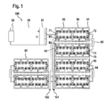
- FIG. 1 illustrates a schematic top view of a battery system 100 according to the prior art.
- a plurality of battery modules 90 are electrically connected in series between a first system terminal 101 with positive polarity and a second system terminal 102 with negative polarity.
- Each battery module 90 comprises ten stacked prismatic battery cells 80, with five parallel connected pairs of battery cells 80 connected in series between a first module terminal 93 with positive polarity and a second module terminal 94 with negative polarity.
- Each battery module 90 further comprises a cell supervision circuit (CSC) 70 disposed on top of the stacked battery cells 80.
- Each CSC 70 comprises a printed circuit board as a circuit carrier with a plurality of contact pads, contact metallizations and integrated circuits that are surface mounted to the carrier.
- the CSC 70 is electrically connected to the terminal of each battery cell 80 and is configured for monitoring and balancing the voltage of the individual battery cells 80.
- the CSC 70 might comprise a plurality of resistors that are connectable to the individual cells 80 for passively balancing the module 90 by dissipating energy of the highest voltage battery cells 80.
- Each CSC 70 further comprises a first signal port 71 and a second signal port 72 that are configured to interconnect the CSC 70 for data transmission.
- the illustrated battery system 100 further comprises a battery management system (BMS) 50 that comprises a VEH converter 52 for connecting the BMS to a 12 V board net of an electric vehicle.
- the BMS 50 further comprises a high voltage (HV) connector 51 that is configured for safely connecting the voltage domain of the plurality of battery modules 90 to the voltage domain of the board net.
- the battery management system 50 is configured for communication with electric consumers connected to the board net as well as with the battery modules 90. For communicating, the BMS 50 is coupled to the modules 90 via a daisy chain configuration.
- the BMS 50 is coupled via a pair of data lines to the first signal port 71 of a first battery module 91 that is an outermost battery module 90, i.e. connected to a battery system terminal 101.
- the second signal port 72 of the first battery module 91 is coupled to a first signal port 71 of a second battery module 92 again via a pair of data lines.
- a two wire data connection spans across the battery system 100 and in between the CSCs 70 of the battery modules 90.
- the battery system 100 comprises a plurality of busbars 60, wherein most of the busbars 60 are electrically connected between a second module terminal 94 of a first battery module 91 and a first module terminal 93 of a second battery terminal 92.
- a single busbar 60 interconnects a first module terminal 93 of an outermost battery cell 90 with the first system terminal 101 and another single busbar 60 interconnects a second module terminal 94 of an outermost battery cell 90 with the second system terminal 102.
- the two wire data connections and the busbars 60 are arranged within same regions around the battery modules 90.
- expensive electrical isolation means are required to avoid unwanted coupling between the busbars 70 and the two wire data connections.
- FIG 2 illustrates a battery system 100 according to an embodiment of the present invention. Elements and features that are identical to elements and features of the battery system 100 according to Figure 1 are denoted with identical reference signs.
- a second signal port 72 of a CSC 70 of a first battery module 91 is electronically connected with a first signal port 71 of a CSC 70 of a second battery module 92 via a single wire first data line 61 that is configured for data transmission.
- a second data line 62 electronically connects the second signal port 72 of the CSC 70 of the first battery module 91 with a second module terminal 94 of the first battery module 91.
- a third data line 63 electronically interconnects a first module terminal 93 of a second battery module 92 with a first signal port 71 of a CSC 70 of the second battery module 92.
- the combination of the second data line 62, the busbar 60 and the third data line 63 constitutes a second data connection.
- this second data connection constitutes a two signal path communication pathway between adjacent battery modules 91, 92.
- a full second data line between the signal ports 71, 72 of adjacent battery modules 91, 92 can be omitted.
- costs of material as well as wiring complexity are reduced in a battery system 100 according to the present invention.
- crosstalk between power transmission and data transmission can be avoided or at least reduced with the battery system 100 according to the invention.
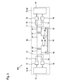
- Figure 3 illustrates a schematic circuit diagram of a communication circuit 200 for a battery system 100 according to the present invention.
- the illustrated communication circuit depicts the necessary or advantageous elements for realizing the system 100 of Figure 2 .
- the illustrated circuit 200 comprises a CSC 70 of a first battery module 91 that is electronically connected with a CSC 70 of a second battery module 92 via a communication pathway 68.
- the assignment of certain circuit elements, e.g. modulators, demodulators and switches, to the CSCs 70 is only exemplarily; these components could also be assigned to the communication pathway 68.
- the CSC 70 of the first battery module 91 comprises a first transceiver 41 that is electronically connect to a first modulator 73 and is configured to provide binary signals, e.g. in form of a high voltage level VDD and a low voltage level VSS, to the first modulator 73.
- the first transceiver 41 is further electronically connected to a first demodulator 74 and is configured to receive binary signals from the first demodulator 74.
- a pair of first switches 77 provides a switchable electrical connection from the first modulator 73 to a first data line 61 and to a second data line 62, wherein a pair of second switches 78 provides a switchable electrical connection from the first demodulator 74 to the first data line 61 and the second date line 62.
- the dashed line between the CSC 70 of the first battery module 91 and the signal pathway 68 can also be interpreted as indicating a second signal port 72.
- the CSC 70 of the second battery module 92 comprises a second transceiver 42 that is electronically connect to a second modulator 75 and is configured to provide binary signals, e.g. in form of a high voltage level VDD and a low voltage level VSS, to the second modulator 75.
- the second transceiver 42 is further electronically connected to a second demodulator 76 and is configured to receive binary signals from the second demodulator 76.
- a pair of second switches 78 provides a switchable electrical connection from the second modulator 75 to the first data line 61 and to a third data line 63, wherein a pair of first switches 77 provides a switchable electrical connection from the second demodulator 76 to the first data line 61 and the third date line 63.
- the dashed line between the CSC 70 of the second battery module 92 and the signal pathway 68 can also be interpreted as indicating a first signal port 71.
- the set of first switches 77 are commonly operated such that either all first switches 77 are closed, i.e. to provide a conducting connection, or all first switches 77 are opened, i.e. to separate the conducting connection.
- the set of second switches 78 are also commonly operated such that either are all second switches 78 are closed, i.e. to provide a conducting connection, or all second switches 78 are opened, i.e. to separate the conducting connection.
- the set of first switches 77 and the set of second switches might be actuated via one or more relays (not shown).
- the communication pathway 68 comprises a first data line 61 and a second data line 62 that are electrically connected to the second signal port 72 of the CSC 70 of the first battery module 91.
- a first isolation transformer 66 is arranged within the first data line 61 and the second data line 62 .
- the first isolation transformer 66 comprises a first inductance and a second inductance, wherein the first inductance is arranged in a first circuit that is formed of segments of the first data line 61 and the second data line 62, one pair first or second switches 77, 78 and the first modulator 73 or first demodulator 74.
- the second data line 62 is electrically connected to the busbar 60, wherein the busbar 60 as a whole interconnects a second module terminal 94 of the first battery module 91 with a first module terminal 93 of a second battery module 92.
- a first filter capacitor 64 is arranged in the second data line 62.
- the first data line 61 and a third data line 63 are further electrically connected to a first signal port 71 of a second battery module 92.
- the third data line 63 is electrically connected to the busbar 60 near the CSC 70 of the second battery module 92.
- a second filter capacitor 65 is arranged in the third data line 63.
- a second isolation transformer 67 is arranged within the first data line 61 and the third data line 63.
- the first isolation transformer 67 comprises a first inductance and a second inductance, wherein the second inductance is arranged in a third circuit that is formed of segments of the first data line 61 and the third data line 63, one pair first or second switches 77, 78 and the second modulator 75 or second demodulator 76.
- the second inductance of the first isolation transformer 66 and the first inductance of the second isolation transformer 67 are arranged in a second circuit that is formed of segments of the first data line 61, the second data line 62, the third data line 63 and the busbar 60.
- the second circuit further comprises the first and second filter capacitors 64, 65.
- the first transceiver 42 transmits binary signals to the first modulator 73 that modulates the signals via a FSK modulation scheme onto a HF carrier frequency.
- the set of first switches 77 is closed and the set of second switches 78 is opened such that the first modulator 73 feeds the signal into the first circuit, i.e. the first data line 61 and the second data line 62.
- the signal passes the first isolation transformer 66, while DC components and low frequency disturbances in the signal are blocked.
- the signal is transmitted via the second circuit, i.e.
- the second filter capacitor 65 blocks DC components at the busbar 60 from being transmitted to the second demodulator 76 and further isolates the voltage level in the CSC 70 of the second battery module 92 from the voltage level of the busbar 60.
- the second demodulator 76 demodulates the signal via a FSK demodulation scheme and transmits binary signals to the second transceiver 42 of the second battery module 92. In the first operation state the CSC 70 of the first battery module 91 thus transmits signals to the CSC 70 of the second battery module 92.
- the second transceiver 42 transmits binary signals to the second modulator 75 that modulates the signals via a FSK modulation scheme onto a HF carrier frequency.
- the set of second switches 78 is closed and the set of first switches 77 is opened such that the second modulator 75 feeds the signal into the third circuit, i.e. the first data line 61 and the third data line 63.
- the signal passes the first isolation transformer 67, while DC components and low frequency disturbances in the signal are blocked.
- the signal is transmitted via the second circuit, i.e.
- the first filter capacitor 64 blocks DC components at the busbar 60 from being transmitted to the first demodulator 74 and further isolates the voltage level in the CSC 70 of the first battery module 91 from the voltage level of the busbar 60.
- the first demodulator 74 demodulates the signal via a FSK demodulation scheme and transmits binary signals to the first transceiver 41 of the first battery module 91.
- the CSC 70 of the second battery module 92 thus transmits signals to the CSC 70 of the first battery module 91.
- the first and second switches 77, 78 determine thus the operation state of the communication circuit 200 and the communication direction.
- the electronic or electric devices and/or any other relevant devices or components according to embodiments of the present invention described herein may be implemented utilizing any suitable hardware, firmware (e.g. an application-specific integrated circuit), software, or a combination of software, firmware, and hardware.
- the various components of these devices may be formed on one integrated circuit (IC) chip or on separate IC chips.
- the various components of these devices may be implemented on a flexible printed circuit film, a tape carrier package (TCP), a printed circuit board (PCB), or formed on one substrate.
- the electrical connections or interconnections described herein may be realized by wires or conducting elements, e.g. on a PCB or another kind of circuit carrier.
- the conducting elements may comprise metallization, e.g. surface metallizations and/or pins, and/or may comprise conductive polymers or ceramics. Further electrical energy might be transmitted via wireless connections, e.g. using electromagnetic radiation and/or light.
- the various components of these devices may be a process or thread, running on one or more processors, in one or more computing devices, executing computer program instructions and interacting with other system components for performing the various functionalities described herein.
- the computer program instructions are stored in a memory which may be implemented in a computing device using a standard memory device, such as, for example, a random access memory (RAM).
- the computer program instructions may also be stored in other non-transitory computer readable media such as, for example, a CD-ROM, flash drive, or the like.
Landscapes
- Engineering & Computer Science (AREA)
- General Chemical & Material Sciences (AREA)
- Chemical & Material Sciences (AREA)
- Chemical Kinetics & Catalysis (AREA)
- Electrochemistry (AREA)
- Power Engineering (AREA)
- Manufacturing & Machinery (AREA)
- Life Sciences & Earth Sciences (AREA)
- Sustainable Development (AREA)
- Sustainable Energy (AREA)
- Transportation (AREA)
- Mechanical Engineering (AREA)
- Charge And Discharge Circuits For Batteries Or The Like (AREA)
- Secondary Cells (AREA)
Abstract
Description
- The present invention relates to a battery system, to a communication circuit for a battery system and to a vehicle with such a battery system and/or such a communication circuit.
- A rechargeable or secondary battery differs from a primary battery in that it can be repeatedly charged and discharged, while the latter provides only an irreversible conversion of chemical to electrical energy. Low-capacity rechargeable batteries are used as power supply for small electronic devices, such as cellular phones, notebook computers and camcorders, while high-capacity rechargeable batteries are used as the power supply for hybrid vehicles and the like.
- In general, rechargeable batteries include an electrode assembly including a positive electrode, a negative electrode, and a separator interposed between the positive and negative electrodes, a case receiving the electrode assembly, and an electrode terminal electrically connected to the electrode assembly. An electrolyte solution is injected into the case in order to enable charging and discharging of the battery via an electrochemical reaction of the positive electrode, the negative electrode, and the electrolyte solution. The shape of the case, e.g. cylindrical or rectangular, depends on the battery's intended purpose.
- Rechargeable batteries may be used as a battery module formed of a plurality of unit battery cells coupled in series and/or in parallel so as to provide a high energy density, e.g. for motor driving of a hybrid vehicle. That is, the battery module is formed by interconnecting the electrode terminals of the plurality of unit battery cells depending on a required amount of power and in order to realize a high-power rechargeable battery, e.g. for an electric vehicle.
- Battery modules can be constructed either in block design or in modular design. In block designs, each battery cell is coupled to a common current collector structure and a common battery management system. In modular designs, pluralities of battery cells are connected to form submodules and several submodules are connected to form the battery module. Battery management functions may be realized either on module or submodule level and thus interchangeability of the components is improved. One or more battery modules are mechanically and electrically integrated, equipped with a thermal management system and set up for communication with one or more electrical consumers in order to form a battery system.
- To provide thermal control of a battery system a thermal management system is required to safely use the at least one battery module by efficiently emitting, discharging and/or dissipating heat generated from its rechargeable batteries. If the heat emission/discharge/dissipation is not sufficiently performed, temperature deviations occur between respective battery cells, such that the at least one battery module cannot generate a desired amount of power. In addition, an increase of the internal temperature can lead to abnormal reactions occurring therein and thus charging and discharging performance of the rechargeable deteriorates and the life-span of the rechargeable battery is shortened. Thus, cooling devices for effectively emitting/discharging/dissipating heat from the cells is required.
- For meeting the dynamic power demands of various electrical consumers connected to the battery system a static control of battery power output and charging is not sufficient. Thus, steady exchange of information between the battery system and the controllers of the electrical consumers is required. This information includes the battery systems actual state of charge (SoC), potential electrical performance, charging ability and internal resistance as well as actual or predicted power demands or surpluses of the consumers. Battery systems usually comprise a battery management system (BMS) for processing this information.
- The BMS is usually coupled to the controller of one or more electrical consumers as well as to each of the battery modules of the battery system. According to the prior art, the communication between the BMS and the battery modules is mainly provided using a two wire protocol. A known protocol is based on serial peripheral interface (SPI) bus system and utilizes the BMS to translate a common SPI signal into a customized SPI signal. The customized SPI signal is used for communication of the BMS with the battery modules. Other known approaches utilize galvanic isolated SPI systems or galvanic isolated controller area network (CAN) bus systems for communication between the BMS and the battery modules.
- The wiring complexity and the production costs of the two wire communication networks are high due to the required amount of electric conductors. Further, a risk for reversed polarity persists and thus unsolved safety issues remain in the battery system.
- It is thus an object of the present invention to overcome or reduce at least some of the drawbacks of the prior art and to provide a battery system with a communication network between individual battery modules that has low wiring complexity and manufacturing costs.
- One or more of the drawbacks of the prior art could be avoided or at least reduced by means of the present invention. In particular, a battery system is provided that comprises a first system terminal and a second system terminal and a plurality of battery modules that are connected in series between the first system terminal and the second system terminal. Each battery module comprises a plurality of battery cells that are connected in series and/or in parallel between a first module terminal and a second module terminal of the respective battery module. Each battery module further comprises a cell supervision circuit (CSC) that comprises a first signal port and a second signal port. The CSC is preferably configured to monitor the cell voltages of some or each of the battery module's battery cells and may further be configured to actively or passively balance the voltages of the individual battery cells within the module. According to the present invention, the CSC is further configured to maintain the communication between the battery modules among each other and the BMS.
- The battery system further comprises a plurality of busbars, wherein each busbar is electrically interconnecting a second module terminal of a first battery module and a first module terminal of second battery module. In other words, the busbar provides the power connections between the individual battery modules. The battery system further comprises a plurality of first data lines. According to the present invention, the second signal port of a first battery module and the first signal port of a second battery module are coupled, i.e. electronically coupled, via one of a plurality of first data lines and via one of the plurality of busbars. Further, the cell supervision circuits are configured to transmit and receive signals via the first data lines and via the busbars. In other words, the present invention provides a communication network for a battery system comprising busbars, wherein one data line can be omitted and is replaced by the busbars that is used as signal line as well. Hence, with the battery system according to the invention two wire protocols can be continued to be utilized in a one wire communication setup. Thus, costs of material and wiring complexity are reduced.
- In the context of the present invention a first system terminal and second system terminal are understood to have different polarities. Further, a first module terminal and a second module terminal are understood to have different polarities. A first signal port and a second signal port are understood as a pair of a signal input port and a signal output port during a determined operation state of the battery system. However, due to changes of the operation state of the battery system a signal input port can become a signal output port and vise versa. It has to be further understood, that a first battery module and a second battery module refer to a pair of adjacent battery modules within the battery system. Except of the outermost battery modules of the battery system, a battery module that is a first battery module with respect to a certain second battery module can be a second battery module with respect to a certain first battery module at the same time. The outermost battery modules are always either a first or a second battery module.
- The busbars are preferably made of an electrically conductive material, e.g. aluminum, and have a strip-like shape with a uniform busbar width and a uniform busbar height. However, the shape of the busbars may be freely adapted to meet individual requirements of a specific battery design, e.g. in view of a limited installation space. In particular, the busbar can be in the form of straight, bend or arbitrary curved belts, bands, ribbons, ribs or rails. The first data lines or further data lines may comprise any kind of wire, cable, metallization or an electrically conducting polymer. The data lines may be connected to the signal ports, the busbars or the terminals via interconnectors, e.g. plugs, or via firmly bonds, e.g. via wire or solder bonds.
- In a preferred embodiment, the cell supervision circuits are configured to transmit and receive analogous signals via the first data lines and via the busbars. Therein the signals are preferably modulated on alternating currents. Advantageously, this kind of communication is widely independent of the voltage levels of the individual battery modules. Thus, less error-prone and secure communication can be provided even between unbalanced battery modules. Particularly preferred, the second signal port of the first battery module is capacitively coupled to the busbar and the busbar is capacitively coupled to the first signal port of the second battery module. The capacitive coupling preferably decouples the CSC from the voltage potentials of and the voltage drop over the busbars. This helps to protect the CSC from disturbances on the busbars. Analogous signals modulated on AC carrier currents with sufficient high frequency can pass the capacitive coupling. Another advantage of using a capacitance is that it is not absolute necessary to use the same bus bar. When different bus bars are used, it applies only one module voltage between the pins connected to the bus bar.
- According to an embodiment, the battery system further comprises a plurality of second data lines, wherein each second data line electrically interconnects the second signal port, e.g. the signal output port, of the first battery module with one of the second module terminal of the first battery module and the busbar. Further preferred, the battery system comprises a plurality of third data lines, wherein each third data line electrically interconnects one of the busbar and the first module terminal of the second battery module with the first signal port, e.g. the signal input port, of the second battery module. In other words, the coupling between the busbar and the signal ports does not have to occur directly. Rather, a short data line segment may connect a signal port with a busbar, either directly or via a module terminal that terminates the busbar. Thus, the use of second data lines might be drastically reduced.
- In a particularly preferred embodiment, the battery system further comprises a plurality of first high pass filters, wherein each first high pass filter is disposed in, i.e. arranged in and electrically connected to, one of the second data lines. Further preferred, the battery system comprises a plurality of second high pass filters, wherein each second high pass filter is disposed in, i.e. arranged in and electrically connected to, one of the third data lines. The first and second high pass filters are utilized to block low frequency AC components or DC components from being transmitted from the busbar to the CSCs of the battery modules. According to this embodiment, the high pass filters are arranged outside the CSCs. However, the high pass filters may also be arranged within the CSCs. Further preferred, at least one first high pass filter comprises a first capacitor and at least one second high pass filter comprises a second capacitor. Filter capacitors are a simple way to realize a high pass filter as well as capacitive coupling. According to this embodiment, capacitive coupling occurs outside the CSCs that are particularly protected from disturbances and voltage peaks on the busbars.
- In order to further isolate the CSCs electronics from the power transmission on the busbars, the battery system further comprises a plurality of first isolation transformers, wherein each first isolation transformer is interconnected between the second signal port of a first battery module and a busbar. In detail, the first isolation transformer is also interconnected between the second signal port of a first battery module and a first data line. In other words, the second signal port of the first battery module and a first inductance of the first isolation transformer are arranged in a first circuit, wherein the first data line, the busbar and a second inductance of the first isolation transformer are arranged in a second circuit, wherein the first isolation transformer inductively couples the first and the second circuit.
- The battery system further comprises a plurality of second isolation transformers, wherein each second isolation transformer is interconnected between a busbar and the first signal port of a second battery module. In detail, the second isolation transformer is also interconnected between the first signal port of a second battery module and a first data line. In other words, a first inductance of the second isolation transformer is also arranged in the second circuit, wherein a second inductance of the second isolation transformer and the first signal port of the second battery module are arranged in a third circuit and wherein the second isolation transformer inductively couples the first and the second circuit.
- Hence, the transformers introduce additional galvanic isolation between the busbars and the CSCs electronics in order to increase safety. The galvanic isolation is further introduced in the first data line between adjacent battery modules and thus disturbances on the first data line are reduced. Particularly, the galvanic isolation of adjacent battery modules decouples the communication signals from the different voltage levels at the connected terminals of the battery modules, wherein the modulated analogous signals can pass the transformers.
- According to a further preferred embodiment of the present invention, each of the battery modules, preferably each of the cell supervision circuits, further comprises at least one modulator and at least one demodulator. The modulators/demodulators may be integrated into the CSCs such that modulated signals already apply to the signal ports of the CSCs. Hence, signal modulation is performed distant to the busbars and any unwanted coupling of power line transmission and modulation or demodulation is avoided, particularly due to the usually good electromagnetic shielding of the CSCs. Alternatively, the modulators/demodulators can be disposed outside the CSCs and e.g. can be part of an additional chip on the battery modules. Thus binary signals may apply to the CSC's signal ports and modulation/demodulation of these signals might occur between CSC and busbar.
- Particularly preferred, each of the modulators is configured to perform a frequency-shift or phase-shift keying modulation scheme and each of the demodulators is configured to perform a frequency-shift or phase-shift keying demodulation scheme. However, the modulators/demodulators may be configured to perform any kind of analogous or digital modulation technique. The used modulation/demodulation scheme depends on the signal format that is outputted to the modulator or the compatibility of the component that receive signals from the demodulator. Alternatively preferred, the modulators/demodulators are configured to perform amplitude shift-keying or quadrature amplitude modulation. The modulators/demodulators may also be configured to perform analogous (de-)modulation.
- According to a further preferred embodiment, the battery system comprises a set of first switches that are interconnected between the modulator of the first battery module and the busbar and between the busbar and the demodulator of the second battery module. In detail, the set of first switches is also interconnected between the modulator of the first battery module and the first data line and between the first data line and the demodulator of the second battery module. In other words, the set of first switches comprises a first pair of first switches and a second pair of first switches, wherein the first pair of first switches is interconnected between two outputs of the modulator of the first battery module and the first data line and the busbar and wherein the second pair of first switches is interconnected between the first data line and the busbar and two inputs of the demodulator of the second battery module.
- Further preferred, the battery system comprises a set of second switches that are interconnected between the demodulator of the first battery module and the busbar and between the busbar and the modulator of the second battery module. In detail, the set of second switches is also interconnected between the demodulator of the first battery module and the first data line and between the first data line and the modulator of the second battery module. In other words, the set of second switches comprises a first pair of second switches and a second pair of second switches, wherein the first pair of second switches is interconnected between two outputs of the demodulator of the first battery module and the first data line and the busbar and wherein the second pair of second switches is interconnected between the first data line and the busbar and two inputs of the modulator of the second battery module.
- According to this preferred embodiment, the set of first switches is set conducting, i.e. closed, for transmitting signals from the first battery module to the second battery module and the second set of switches is set conducting, i.e. closed, for transmitting signals from the second battery module to the first battery module. In other words, bidirectional communication can be realized in the battery system of the invention, wherein the communication direction is set by setting either the first or the second pair of switches conducting.
- As already mentioned, a battery module might be either a first or a second battery module with respect to different neighboring battery modules. However, the first signal port of one of the outermost battery modules, i.e. a first battery module, is coupled to battery management system (BMS), wherein the BMS is coupled to and communicates with each of the plurality of battery modules via a daisy chain configuration. Preferably, the BMS is further coupled to a board net of a vehicle, e.g. to a 12 V board net of a vehicle and comprises a high voltage (HV) connector for safely coupling to the plurality of battery modules. The HV connector may comprise a buck converter or a buck boost converter.
- Another aspect of the present invention relates to a communication circuit for a battery system, comprising a first transceiver of a cell supervision circuit of a first battery module, wherein the transceiver is electrically connected to a first modulator and a first demodulator. The communication circuit further comprises a second transceiver of a cell supervision circuit of a second battery module, wherein the transceiver is electrically connected to a second modulator and a second demodulator. The first and second transceivers are configured to transmit and receive binary signals that were either provided by the BMS or another battery module (in the form of analogous signals) or generated by the respective CSC itself.
- In the communication circuit a first data line is interconnected between the first transceiver and the second transceiver. Further, a busbar is configured and interconnected as a power line between the first battery module and the second battery module, i.e. between the second module terminal of the first battery module and the first module terminal of the second battery module, and is further interconnected, i.e. electronically coupled, between the first transceiver and the second transceiver. In a preferred embodiment, the busbar is connected to the first transceiver, i.e. to the first modulator or the first demodulator, via a second data line. Further preferred, the busbar is connected to the second transceiver, i.e. the second modulator or the second demodulator, via a third data line.
- According to a preferred embodiment of the communication circuit, the first and second modulator and demodulator are configured to transmit and receive analogous signals via the first data lines and the busbars. In other words, they use a circuit constituted at least by the first data line and the busbar between the first and the second transceiver to transmit and receive analogous signals. The analogous signals are preferably modulated signals fed into that circuit. In order to decouple the modulated AC signals from the power line transmission on the busbars, the first transceiver, i.e. the first modulator or first demodulator, is preferably capacitively coupled to the busbar and the busbar is preferably capacitively coupled to the second transceiver, i.e. to the second modulator or the second demodulator.
- The communication circuit further comprises a set of first switches that is configured for electrically connecting or disconnecting the first modulator and the second demodulator to or from the first data line and to or from the busbar and further comprises a set of second switches that is configured for electrically connecting or disconnecting the first demodulator and the second modulator to or from the first data line and to or from the busbar. The switching state of the sets of switches determines the communication direction within the communication circuit either from first to second or from second to first battery module.
- According to a preferred embodiment, the communication circuit further comprises a first isolation transformer that is interconnected between the first transceiver and the busbar and a second isolation transformer that is interconnected between the busbar and the second transceiver. In detail, the first isolation transformer is also interconnected between the first transceiver and the first data line. In other words, the first transceiver and a first inductance of the first isolation transformer are arranged in a first circuit, wherein the first data line, the busbar and a second inductance of the first isolation transformer are arranged in a second circuit and wherein the first isolation transformer inductively couples the first and the second circuit. In detail, the second isolation transformer is interconnected between the second transceiver and the first data line. In other words, a first inductance of the second isolation transformer is also arranged in the second circuit, wherein a second inductance of the second isolation transformer and second transceiver are arranged in a third circuit and wherein the second isolation transformer inductively couples the second and the third circuit.
- Further preferred, the communication circuit comprises a first high pass filter that is interconnected between one of the first modulator and the first demodulator and the busbar and comprises a second high pass filter that is interconnected between the busbar and one of the second modulator and the second demodulator. Preferably, the first high pass filter is disposed in, i.e. arranged in and electrically connected to, the second data line and the second high pass filter is disposed in, i.e. arranged in and electrically connected to, the third data line. The first and second high pass filters are utilized to block low frequency AC components or DC components from being transmitted from the busbar to the transceivers. Further preferred, the first high pass filter comprises a first capacitor and the second high pass filter comprises a second capacitor. The filter capacitors realize high pass filters as well as capacitive coupling.
- Another aspect of the present invention relates to an electric vehicle, comprising a battery system according to the invention as described above and/or a communication circuit according to the invention as described above. Further aspects of the present invention could be learned from the dependent claims or the following description.
- Features will become apparent to those of ordinary skill in the art by describing in detail exemplary embodiments with reference to the attached drawings in which:
-
Fig. 1 illustrates a schematic top view of a battery system according to the prior art; -
Fig. 2 illustrates a schematic top view of a battery system according to an embodiment; and -
Fig. 3 illustrates a schematic circuit diagram of a communication circuit according to an embodiment. - Reference will now be made in detail to embodiments, examples of which are illustrated in the accompanying drawings. Effects and features of the exemplary embodiments, and implementation methods thereof will be described with reference to the accompanying drawings. In the drawings, like reference numerals denote like elements, and redundant descriptions are omitted. The present invention, however, may be embodied in various different forms, and should not be construed as being limited to only the illustrated embodiments herein. Rather, these embodiments are provided as examples so that this disclosure will be thorough and complete, and will fully convey the aspects and features of the present invention to those skilled in the art.
- Accordingly, processes, elements, and techniques that are not considered necessary to those having ordinary skill in the art for a complete understanding of the aspects and features of the present invention may not be described. In the drawings, the relative sizes of elements, layers, and regions may be exaggerated for clarity.
- As used herein, the term "and/or" includes any and all combinations of one or more of the associated listed items. Further, the use of "may" when describing embodiments of the present invention refers to "one or more embodiments of the present invention." In the following description of embodiments of the present invention, the terms of a singular form may include plural forms unless the context clearly indicates otherwise.
- It will be understood that although the terms "first" and "second" are used to describe various elements, these elements should not be limited by these terms. These terms are only used to distinguish one element from another element. For example, a first element may be named a second element and, similarly, a second element may be named a first element, without departing from the scope of the present invention. As used herein, the term "and/or" includes any and all combinations of one or more of the associated listed items. Expressions such as "at least one of," when preceding a list of elements, modify the entire list of elements and do not modify the individual elements of the list.
- As used herein, the term "substantially," "about," and similar terms are used as terms of approximation and not as terms of degree, and are intended to account for the inherent deviations in measured or calculated values that would be recognized by those of ordinary skill in the art. Further, if the term "substantially" is used in combination with a feature that could be expressed using a numeric value, the term "substantially" denotes a range of +/- 5% of the value centered on the value.
-
Figure 1 illustrates a schematic top view of abattery system 100 according to the prior art. Therein a plurality ofbattery modules 90 are electrically connected in series between afirst system terminal 101 with positive polarity and asecond system terminal 102 with negative polarity. Eachbattery module 90 comprises ten stackedprismatic battery cells 80, with five parallel connected pairs ofbattery cells 80 connected in series between afirst module terminal 93 with positive polarity and asecond module terminal 94 with negative polarity. - Each
battery module 90 further comprises a cell supervision circuit (CSC) 70 disposed on top of the stackedbattery cells 80. EachCSC 70 comprises a printed circuit board as a circuit carrier with a plurality of contact pads, contact metallizations and integrated circuits that are surface mounted to the carrier. TheCSC 70 is electrically connected to the terminal of eachbattery cell 80 and is configured for monitoring and balancing the voltage of theindividual battery cells 80. TheCSC 70 might comprise a plurality of resistors that are connectable to theindividual cells 80 for passively balancing themodule 90 by dissipating energy of the highestvoltage battery cells 80. EachCSC 70 further comprises afirst signal port 71 and asecond signal port 72 that are configured to interconnect theCSC 70 for data transmission. - The illustrated
battery system 100 further comprises a battery management system (BMS) 50 that comprises aVEH converter 52 for connecting the BMS to a 12 V board net of an electric vehicle. TheBMS 50 further comprises a high voltage (HV)connector 51 that is configured for safely connecting the voltage domain of the plurality ofbattery modules 90 to the voltage domain of the board net. Thebattery management system 50 is configured for communication with electric consumers connected to the board net as well as with thebattery modules 90. For communicating, theBMS 50 is coupled to themodules 90 via a daisy chain configuration. - In the daisy chain configuration, the
BMS 50 is coupled via a pair of data lines to thefirst signal port 71 of afirst battery module 91 that is anoutermost battery module 90, i.e. connected to abattery system terminal 101. Thesecond signal port 72 of thefirst battery module 91 is coupled to afirst signal port 71 of asecond battery module 92 again via a pair of data lines. Thus, a two wire data connection spans across thebattery system 100 and in between theCSCs 70 of thebattery modules 90. Additionally to this two wire data connection, thebattery system 100 comprises a plurality ofbusbars 60, wherein most of thebusbars 60 are electrically connected between asecond module terminal 94 of afirst battery module 91 and afirst module terminal 93 of asecond battery terminal 92. However, asingle busbar 60 interconnects afirst module terminal 93 of anoutermost battery cell 90 with thefirst system terminal 101 and anothersingle busbar 60 interconnects asecond module terminal 94 of anoutermost battery cell 90 with thesecond system terminal 102. - As can be seen in
Figure 1 , the two wire data connections and thebusbars 60 are arranged within same regions around thebattery modules 90. As installation space in thebattery system 100 is sparse, expensive electrical isolation means are required to avoid unwanted coupling between thebusbars 70 and the two wire data connections. -
Figure 2 illustrates abattery system 100 according to an embodiment of the present invention. Elements and features that are identical to elements and features of thebattery system 100 according toFigure 1 are denoted with identical reference signs. - In the
battery system 100 ofFigure 2 , the two wire data connections of the prior art battery system are replaced by a substantially one wire data connection. Therefore, asecond signal port 72 of aCSC 70 of afirst battery module 91 is electronically connected with afirst signal port 71 of aCSC 70 of asecond battery module 92 via a single wirefirst data line 61 that is configured for data transmission. Further, asecond data line 62 electronically connects thesecond signal port 72 of theCSC 70 of thefirst battery module 91 with asecond module terminal 94 of thefirst battery module 91. Further, athird data line 63 electronically interconnects afirst module terminal 93 of asecond battery module 92 with afirst signal port 71 of aCSC 70 of thesecond battery module 92. The combination of thesecond data line 62, thebusbar 60 and thethird data line 63 constitutes a second data connection. - Together with the
first data line 61 as a first data connection this second data connection constitutes a two signal path communication pathway betweenadjacent battery modules battery system 100 according to the present invention a full second data line between thesignal ports adjacent battery modules battery system 100 according to the present invention. Further, crosstalk between power transmission and data transmission can be avoided or at least reduced with thebattery system 100 according to the invention. -
Figure 3 illustrates a schematic circuit diagram of acommunication circuit 200 for abattery system 100 according to the present invention. The illustrated communication circuit depicts the necessary or advantageous elements for realizing thesystem 100 ofFigure 2 . - The illustrated
circuit 200 comprises aCSC 70 of afirst battery module 91 that is electronically connected with aCSC 70 of asecond battery module 92 via acommunication pathway 68. The assignment of certain circuit elements, e.g. modulators, demodulators and switches, to theCSCs 70 is only exemplarily; these components could also be assigned to thecommunication pathway 68. - In the illustrated
communication circuit 200 theCSC 70 of thefirst battery module 91 comprises afirst transceiver 41 that is electronically connect to afirst modulator 73 and is configured to provide binary signals, e.g. in form of a high voltage level VDD and a low voltage level VSS, to thefirst modulator 73. Thefirst transceiver 41 is further electronically connected to afirst demodulator 74 and is configured to receive binary signals from thefirst demodulator 74. A pair offirst switches 77 provides a switchable electrical connection from thefirst modulator 73 to afirst data line 61 and to asecond data line 62, wherein a pair ofsecond switches 78 provides a switchable electrical connection from thefirst demodulator 74 to thefirst data line 61 and thesecond date line 62. In the illustrated embodiment of thecommunication circuit 200, the dashed line between theCSC 70 of thefirst battery module 91 and thesignal pathway 68 can also be interpreted as indicating asecond signal port 72. - The
CSC 70 of thesecond battery module 92 comprises asecond transceiver 42 that is electronically connect to asecond modulator 75 and is configured to provide binary signals, e.g. in form of a high voltage level VDD and a low voltage level VSS, to thesecond modulator 75. Thesecond transceiver 42 is further electronically connected to asecond demodulator 76 and is configured to receive binary signals from thesecond demodulator 76. - A pair of
second switches 78 provides a switchable electrical connection from thesecond modulator 75 to thefirst data line 61 and to athird data line 63, wherein a pair offirst switches 77 provides a switchable electrical connection from thesecond demodulator 76 to thefirst data line 61 and thethird date line 63. In the illustrated embodiment of thecommunication circuit 200, the dashed line between theCSC 70 of thesecond battery module 92 and thesignal pathway 68 can also be interpreted as indicating afirst signal port 71. - The set of
first switches 77 are commonly operated such that either allfirst switches 77 are closed, i.e. to provide a conducting connection, or allfirst switches 77 are opened, i.e. to separate the conducting connection. The set ofsecond switches 78 are also commonly operated such that either are allsecond switches 78 are closed, i.e. to provide a conducting connection, or allsecond switches 78 are opened, i.e. to separate the conducting connection. The set offirst switches 77 and the set of second switches might be actuated via one or more relays (not shown). - The
communication pathway 68 comprises afirst data line 61 and asecond data line 62 that are electrically connected to thesecond signal port 72 of theCSC 70 of thefirst battery module 91. Within thefirst data line 61 and the second data line 62 afirst isolation transformer 66 is arranged. Thefirst isolation transformer 66 comprises a first inductance and a second inductance, wherein the first inductance is arranged in a first circuit that is formed of segments of thefirst data line 61 and thesecond data line 62, one pair first orsecond switches first modulator 73 orfirst demodulator 74. Thesecond data line 62 is electrically connected to thebusbar 60, wherein thebusbar 60 as a whole interconnects asecond module terminal 94 of thefirst battery module 91 with afirst module terminal 93 of asecond battery module 92. Further, afirst filter capacitor 64 is arranged in thesecond data line 62. Thefirst data line 61 and athird data line 63 are further electrically connected to afirst signal port 71 of asecond battery module 92. Therein, thethird data line 63 is electrically connected to thebusbar 60 near theCSC 70 of thesecond battery module 92. Further, asecond filter capacitor 65 is arranged in thethird data line 63. Asecond isolation transformer 67 is arranged within thefirst data line 61 and thethird data line 63. Thefirst isolation transformer 67 comprises a first inductance and a second inductance, wherein the second inductance is arranged in a third circuit that is formed of segments of thefirst data line 61 and thethird data line 63, one pair first orsecond switches second modulator 75 orsecond demodulator 76. The second inductance of thefirst isolation transformer 66 and the first inductance of thesecond isolation transformer 67 are arranged in a second circuit that is formed of segments of thefirst data line 61, thesecond data line 62, thethird data line 63 and thebusbar 60. The second circuit further comprises the first andsecond filter capacitors - In a first operation state of the
communication circuit 200 according to the embodiment, thefirst transceiver 42 transmits binary signals to thefirst modulator 73 that modulates the signals via a FSK modulation scheme onto a HF carrier frequency. The set offirst switches 77 is closed and the set ofsecond switches 78 is opened such that thefirst modulator 73 feeds the signal into the first circuit, i.e. thefirst data line 61 and thesecond data line 62. The signal passes thefirst isolation transformer 66, while DC components and low frequency disturbances in the signal are blocked. The signal is transmitted via the second circuit, i.e. thesecond data line 62, thebusbar 60 and thethird data line 63 as well as thefist data line 61 to thesecond demodulator 76 that is connected to the first and third data lines 61, 63 via the first switches 77. Therein, thesecond filter capacitor 65 blocks DC components at thebusbar 60 from being transmitted to thesecond demodulator 76 and further isolates the voltage level in theCSC 70 of thesecond battery module 92 from the voltage level of thebusbar 60. Thesecond demodulator 76 demodulates the signal via a FSK demodulation scheme and transmits binary signals to thesecond transceiver 42 of thesecond battery module 92. In the first operation state theCSC 70 of thefirst battery module 91 thus transmits signals to theCSC 70 of thesecond battery module 92. - In a second operation state of the
communication circuit 200 according to the embodiment, thesecond transceiver 42 transmits binary signals to thesecond modulator 75 that modulates the signals via a FSK modulation scheme onto a HF carrier frequency. The set ofsecond switches 78 is closed and the set offirst switches 77 is opened such that thesecond modulator 75 feeds the signal into the third circuit, i.e. thefirst data line 61 and thethird data line 63. The signal passes thefirst isolation transformer 67, while DC components and low frequency disturbances in the signal are blocked. The signal is transmitted via the second circuit, i.e. thethird data line 63, thebusbar 60 and thesecond data line 62 as well as thefirst data line 61 to thefirst demodulator 74 that is connected to the first and second data lines 61, 62 via the second switches 78. Therein, thefirst filter capacitor 64 blocks DC components at thebusbar 60 from being transmitted to thefirst demodulator 74 and further isolates the voltage level in theCSC 70 of thefirst battery module 91 from the voltage level of thebusbar 60. Thefirst demodulator 74 demodulates the signal via a FSK demodulation scheme and transmits binary signals to thefirst transceiver 41 of thefirst battery module 91. In the first operation state theCSC 70 of thesecond battery module 92 thus transmits signals to theCSC 70 of thefirst battery module 91. The first andsecond switches communication circuit 200 and the communication direction. - The electronic or electric devices and/or any other relevant devices or components according to embodiments of the present invention described herein may be implemented utilizing any suitable hardware, firmware (e.g. an application-specific integrated circuit), software, or a combination of software, firmware, and hardware. For example, the various components of these devices may be formed on one integrated circuit (IC) chip or on separate IC chips. Further, the various components of these devices may be implemented on a flexible printed circuit film, a tape carrier package (TCP), a printed circuit board (PCB), or formed on one substrate. The electrical connections or interconnections described herein may be realized by wires or conducting elements, e.g. on a PCB or another kind of circuit carrier. The conducting elements may comprise metallization, e.g. surface metallizations and/or pins, and/or may comprise conductive polymers or ceramics. Further electrical energy might be transmitted via wireless connections, e.g. using electromagnetic radiation and/or light.
- Further, the various components of these devices may be a process or thread, running on one or more processors, in one or more computing devices, executing computer program instructions and interacting with other system components for performing the various functionalities described herein. The computer program instructions are stored in a memory which may be implemented in a computing device using a standard memory device, such as, for example, a random access memory (RAM). The computer program instructions may also be stored in other non-transitory computer readable media such as, for example, a CD-ROM, flash drive, or the like.
- Also, a person of skill in the art should recognize that the functionality of various computing devices may be combined or integrated into a single computing device, or the functionality of a particular computing device may be distributed across one or more other computing devices without departing from the scope of the exemplary embodiments of the present invention.
-
- 200
- communication circuit
- 100
- battery system
- 101
- first system terminal
- 102
- second system terminal
- 90
- battery module
- 91
- first battery module
- 92
- second battery module
- 93
- first module terminal
- 94
- second module terminal
- 80
- battery cell
- 70
- cell supervision circuit (CSC)
- 71
- first signal port
- 72
- second signal port
- 73
- first modulator
- 74
- first demodulator
- 75
- second modulator
- 76
- second demodulator
- 77
- first switch
- 78
- second switch
- 41
- first transceiver
- 42
- second transceiver
- 60
- busbar
- 61
- first data line
- 62
- second data line
- 63
- third data line
- 64
- first high pass filter / second capacitor
- 65
- second high pass filter / second capacitor
- 66
- first isolation transformer
- 67
- second isolation transformer
- 68
- transmission pathway
- 50
- battery management system (BMS)
- 51
- high voltage (HV) connector
- 52
- VEH converter
Claims (15)
- A battery system (100), comprising:a first system terminal (101) and a second system terminal (101);a plurality of battery modules (90) connected in series between the first system terminal (101) and the second system terminal (101), each battery module (90) comprising a plurality of battery cells (80) connected in series and/or in parallel between a first module terminal (93) and a second module terminal (94) and a cell supervision circuit (70) with a first signal port (71) and a second signal port (72);a plurality of busbars (60), each busbar (60) interconnecting a second module terminal (94) of a first battery module (91) and a first module terminal (93) of second battery module (92),wherein the second signal port (72) of a first battery module (91) and the first signal port (71) of a second battery module (92) are coupled via one of a plurality of first data lines (61) and via one of the plurality of busbars (60), andwherein the cell supervision circuits (70) are configured to transmit and receive signals via the first data lines (61) and the busbars (60).
- The battery system (100) according to claim 1, wherein the cell supervision circuits (70) are configured to transmit and receive analogous signals via the first data lines (61) and the busbars (60).
- The battery system (100) according to claim 1 or 2, wherein the second signal port (72) of the first battery module (91) is capacitively coupled to the busbar (60) and wherein the busbar (60) is capacitively coupled to the first signal port (71) of the second battery module (92).
- The battery system (100) according to any one of the preceding claims, further comprising:a plurality of second data lines (62), each second data line (62) interconnecting the second signal port (72) of the first battery module (91) with one of the second module terminal (94) of the first battery module (91) and the busbar (60); anda plurality of third data lines (63), each third data line (63) interconnecting one of the busbar (60) and the first module terminal (93) of the second battery module (92) with the first signal port (71) of the second battery module (92).
- The battery system (100) according to claim 4, further comprising:a plurality of first high pass filters (64), each first high pass filter (64) being disposed in one of the second data lines (62); anda plurality of second high pass filters (65), each second high pass filter (65) being disposed in one of the third data lines (63).
- The battery system (100) according to claim 5, wherein a first high pass filter comprises a first capacitor (64) and wherein a second high pass filter comprises a second capacitor (65).
- The battery system (100) according to any one of the preceding claims, further comprising
a plurality of first isolation transformers (66), each first isolation transformer (66) being interconnected between the second signal port (71) of a first battery module (92) and a busbar (60); and
a plurality of second isolation transformers (67), each second isolation transformer (67) being interconnected between a busbar (60) and the first signal port (71) of a second battery module (92). - The battery system (100) according to any one of the preceding claims, wherein each of the battery modules (90) further comprises at least one modulator (73,75) and at least one demodulator (74,76).
- The battery system (100) according to claim 8, wherein each of the modulators (73,75) is configured to perform a frequency-shift or phase-shift keying modulation scheme and wherein each of the demodulators (74,76) is configured to perform a frequency-shift or phase-shift keying demodulation scheme.
- The battery system (100) according to claim 8 or 9,
wherein a set of first switches (77) is interconnected between the modulator (73) of the first battery module (91) and the busbar (60) and between the busbar (60) and the demodulator (76) of the second battery module (92),
wherein a set of second switches (78) is interconnected between the demodulator (74) of the first battery module (91) and the busbar (60) and between the busbar (60) and the modulator (75) of the second battery module (92). - The battery system (100) according to claim 10,
wherein the set of first switches (77) is set conducting for transmitting signals from the first battery module (91) to the second battery module (92), and
wherein the second set of switches (78) is set conducting for transmitting signals from the second battery module (92) to the first battery module (91). - The battery system (100) according to any one of the preceding claims, further comprising a battery management system (50) coupled to the first signal port (71) of a first battery module (91) and communicating with each of the plurality of battery modules (90) via a daisy chain configuration.
- A communication circuit (200) for a battery system (100), comprising
a first transceiver (41) of a cell supervision circuit (70) of a first battery module (91) electrically connected to a first modulator (73) and a first demodulator (74);
a second transceiver (42) of a cell supervision circuit (70) of a second battery module (92) electrically connected to a second modulator (75) and a second demodulator (76);
a first data line (61) interconnected between the first transceiver (41) and the second transceiver (42);
a busbar (60) configured and interconnected as a power line between the first battery module (91) and the second battery module (92) and coupled between the first transceiver (41) and the second transceiver (42);
a set of first switches (77) configured for electrically connecting or disconnecting the first modulator (73) and the second demodulator (76) to the first data line (61) and to the busbar (60);
a set of second switches (78) configured for electrically connecting or disconnecting the first demodulator (74) and the second modulator (75) to the first data line (61) and to the busbar (60). - The communication circuit (200) according to claim 13, further comprising
a first isolation transformer (66) interconnected between the first transceiver (41) and the busbar (60) and a second isolation transformer (67) interconnected between the busbar (60) and the second transceiver (42);
a first high-pass filter (64) interconnected between one of the first modulator (73) and the first demodulator (74) and the busbar (60); and/or
a second high-pass filter (65) interconnected between the busbar (60) and one of the second modulator (75) and the second demodulator (76). - An electric vehicle, comprising a battery system (100) according to one of the claims 1 to 12 and/or a communication circuit (200) according to any claims 13 and 14.
Priority Applications (3)
| Application Number | Priority Date | Filing Date | Title |
|---|---|---|---|
| HUE16195810A HUE065447T2 (en) | 2016-10-26 | 2016-10-26 | Battery system, communication circuit for a battery system and vehicle |
| PL16195810.3T PL3316389T3 (en) | 2016-10-26 | 2016-10-26 | Battery system, communication circuit for a battery system and vehicle |
| EP16195810.3A EP3316389B1 (en) | 2016-10-26 | 2016-10-26 | Battery system, communication circuit for a battery system and vehicle |
Applications Claiming Priority (1)
| Application Number | Priority Date | Filing Date | Title |
|---|---|---|---|
| EP16195810.3A EP3316389B1 (en) | 2016-10-26 | 2016-10-26 | Battery system, communication circuit for a battery system and vehicle |
Publications (2)
| Publication Number | Publication Date |
|---|---|
| EP3316389A1 true EP3316389A1 (en) | 2018-05-02 |
| EP3316389B1 EP3316389B1 (en) | 2024-01-03 |
Family
ID=57206173
Family Applications (1)
| Application Number | Title | Priority Date | Filing Date |
|---|---|---|---|
| EP16195810.3A Active EP3316389B1 (en) | 2016-10-26 | 2016-10-26 | Battery system, communication circuit for a battery system and vehicle |
Country Status (3)
| Country | Link |
|---|---|
| EP (1) | EP3316389B1 (en) |
| HU (1) | HUE065447T2 (en) |
| PL (1) | PL3316389T3 (en) |
Cited By (3)
| Publication number | Priority date | Publication date | Assignee | Title |
|---|---|---|---|---|
| CN112467311A (en) * | 2019-09-09 | 2021-03-09 | 大众汽车股份公司 | Traction battery and electrically driven motor vehicle |
| WO2025107567A1 (en) * | 2023-11-24 | 2025-05-30 | 爱士惟科技股份有限公司 | Battery wake-up system |
| DE102024002552A1 (en) * | 2024-08-07 | 2026-02-12 | Mercedes-Benz Group AG | Battery for a motor vehicle, method for manufacturing a battery and motor vehicle |
Citations (3)
| Publication number | Priority date | Publication date | Assignee | Title |
|---|---|---|---|---|
| US20080118819A1 (en) * | 2006-11-17 | 2008-05-22 | Paul Gamboa | Modular battery system |
| EP2493003A1 (en) * | 2011-02-28 | 2012-08-29 | Hitachi, Ltd. | Storage battery system and storage battery module |
| EP2738863A1 (en) * | 2011-07-27 | 2014-06-04 | Yazaki Corporation | Battery status notification unit, bus bar module, assembled battery, and battery status observation system |
-
2016
- 2016-10-26 PL PL16195810.3T patent/PL3316389T3/en unknown
- 2016-10-26 HU HUE16195810A patent/HUE065447T2/en unknown
- 2016-10-26 EP EP16195810.3A patent/EP3316389B1/en active Active
Patent Citations (3)
| Publication number | Priority date | Publication date | Assignee | Title |
|---|---|---|---|---|
| US20080118819A1 (en) * | 2006-11-17 | 2008-05-22 | Paul Gamboa | Modular battery system |
| EP2493003A1 (en) * | 2011-02-28 | 2012-08-29 | Hitachi, Ltd. | Storage battery system and storage battery module |
| EP2738863A1 (en) * | 2011-07-27 | 2014-06-04 | Yazaki Corporation | Battery status notification unit, bus bar module, assembled battery, and battery status observation system |
Cited By (3)
| Publication number | Priority date | Publication date | Assignee | Title |
|---|---|---|---|---|
| CN112467311A (en) * | 2019-09-09 | 2021-03-09 | 大众汽车股份公司 | Traction battery and electrically driven motor vehicle |
| WO2025107567A1 (en) * | 2023-11-24 | 2025-05-30 | 爱士惟科技股份有限公司 | Battery wake-up system |
| DE102024002552A1 (en) * | 2024-08-07 | 2026-02-12 | Mercedes-Benz Group AG | Battery for a motor vehicle, method for manufacturing a battery and motor vehicle |
Also Published As
| Publication number | Publication date |
|---|---|
| EP3316389B1 (en) | 2024-01-03 |
| HUE065447T2 (en) | 2024-05-28 |
| PL3316389T3 (en) | 2024-05-13 |
Similar Documents
| Publication | Publication Date | Title |
|---|---|---|
| EP3432409B1 (en) | Cell supervision circuit carrier, battery system and electric vehicle | |
| CN110290973B (en) | Dual power supply system | |
| US11084397B2 (en) | Power supply system for vehicle with multiple operating voltages | |
| JP6630156B2 (en) | Battery monitoring device | |
| EP3620321B1 (en) | Power supply system | |
| CN109116262B (en) | Battery monitoring system, signal transmission method, and semiconductor device | |
| CN106536261A (en) | Battery system and method for operating same | |
| EP3316440A1 (en) | Battery system with integrated balancing and method for balancing a battery system | |
| EP3316389B1 (en) | Battery system, communication circuit for a battery system and vehicle | |
| JP2015187915A (en) | Power supply device and electric vehicle including the same and power storage device | |
| US9902283B2 (en) | Battery for a motor vehicle, motor vehicle, and method for operating a battery | |
| US12088127B2 (en) | IC chip and circuit system using the same | |
| US11394087B2 (en) | Battery module | |
| US11990785B2 (en) | Battery control device | |
| EP3751715A1 (en) | Control system for a battery system | |
| CN111313119B (en) | Battery module and method for assembling cell monitoring circuit carrier to battery module | |
| US11329564B2 (en) | Control system for a battery system | |
| EP3896773A1 (en) | Control system for a battery system | |
| EP3890095A1 (en) | Battery system with light-based communication | |
| US11881731B2 (en) | Control system for a battery system | |
| EP3795411B1 (en) | Storage battery monitoring system, battery pack, and electric vehicle | |
| US11251699B2 (en) | Relay and battery system including the same | |
| JP6199294B2 (en) | Power supply and management device | |
| US11671181B2 (en) | Battery system with light-based communication | |
| EP3890154A1 (en) | Battery system |
Legal Events
| Date | Code | Title | Description |
|---|---|---|---|
| PUAI | Public reference made under article 153(3) epc to a published international application that has entered the european phase |
Free format text: ORIGINAL CODE: 0009012 |
|
| STAA | Information on the status of an ep patent application or granted ep patent |
Free format text: STATUS: REQUEST FOR EXAMINATION WAS MADE |
|
| 17P | Request for examination filed |
Effective date: 20170601 |
|
| AK | Designated contracting states |
Kind code of ref document: A1 Designated state(s): AL AT BE BG CH CY CZ DE DK EE ES FI FR GB GR HR HU IE IS IT LI LT LU LV MC MK MT NL NO PL PT RO RS SE SI SK SM TR |
|
| AX | Request for extension of the european patent |
Extension state: BA ME |
|
| STAA | Information on the status of an ep patent application or granted ep patent |
Free format text: STATUS: EXAMINATION IS IN PROGRESS |
|
| 17Q | First examination report despatched |
Effective date: 20190306 |
|
| GRAP | Despatch of communication of intention to grant a patent |
Free format text: ORIGINAL CODE: EPIDOSNIGR1 |
|
| STAA | Information on the status of an ep patent application or granted ep patent |
Free format text: STATUS: GRANT OF PATENT IS INTENDED |
|
| RIC1 | Information provided on ipc code assigned before grant |
Ipc: H01M 50/569 20210101ALI20230818BHEP Ipc: H01M 50/505 20210101ALI20230818BHEP Ipc: H01M 50/296 20210101ALI20230818BHEP Ipc: H01M 50/209 20210101ALI20230818BHEP Ipc: G06F 15/17 20060101ALI20230818BHEP Ipc: H01M 10/42 20060101ALI20230818BHEP Ipc: B60L 58/10 20190101ALI20230818BHEP Ipc: H02J 7/00 20060101ALI20230818BHEP Ipc: H01M 10/48 20060101AFI20230818BHEP |
|
| INTG | Intention to grant announced |
Effective date: 20230925 |
|
| GRAS | Grant fee paid |
Free format text: ORIGINAL CODE: EPIDOSNIGR3 |
|
| GRAA | (expected) grant |
Free format text: ORIGINAL CODE: 0009210 |
|
| STAA | Information on the status of an ep patent application or granted ep patent |
Free format text: STATUS: THE PATENT HAS BEEN GRANTED |
|
| AK | Designated contracting states |
Kind code of ref document: B1 Designated state(s): AL AT BE BG CH CY CZ DE DK EE ES FI FR GB GR HR HU IE IS IT LI LT LU LV MC MK MT NL NO PL PT RO RS SE SI SK SM TR |
|
| REG | Reference to a national code |
Ref country code: GB Ref legal event code: FG4D |
|
| REG | Reference to a national code |
Ref country code: CH Ref legal event code: EP |
|
| REG | Reference to a national code |
Ref country code: DE Ref legal event code: R096 Ref document number: 602016085107 Country of ref document: DE |
|
| REG | Reference to a national code |
Ref country code: IE Ref legal event code: FG4D |
|
| REG | Reference to a national code |
Ref country code: SE Ref legal event code: TRGR |
|
| REG | Reference to a national code |
Ref country code: LT Ref legal event code: MG9D |
|
| PG25 | Lapsed in a contracting state [announced via postgrant information from national office to epo] |
Ref country code: ES Free format text: LAPSE BECAUSE OF FAILURE TO SUBMIT A TRANSLATION OF THE DESCRIPTION OR TO PAY THE FEE WITHIN THE PRESCRIBED TIME-LIMIT Effective date: 20240103 |
|
| PG25 | Lapsed in a contracting state [announced via postgrant information from national office to epo] |
Ref country code: ES Free format text: LAPSE BECAUSE OF FAILURE TO SUBMIT A TRANSLATION OF THE DESCRIPTION OR TO PAY THE FEE WITHIN THE PRESCRIBED TIME-LIMIT Effective date: 20240103 |
|
| REG | Reference to a national code |
Ref country code: NL Ref legal event code: MP Effective date: 20240103 |
|
| REG | Reference to a national code |
Ref country code: HU Ref legal event code: AG4A Ref document number: E065447 Country of ref document: HU |
|
| PG25 | Lapsed in a contracting state [announced via postgrant information from national office to epo] |
Ref country code: NL Free format text: LAPSE BECAUSE OF FAILURE TO SUBMIT A TRANSLATION OF THE DESCRIPTION OR TO PAY THE FEE WITHIN THE PRESCRIBED TIME-LIMIT Effective date: 20240103 |
|
| PG25 | Lapsed in a contracting state [announced via postgrant information from national office to epo] |
Ref country code: NL Free format text: LAPSE BECAUSE OF FAILURE TO SUBMIT A TRANSLATION OF THE DESCRIPTION OR TO PAY THE FEE WITHIN THE PRESCRIBED TIME-LIMIT Effective date: 20240103 |
|
| PG25 | Lapsed in a contracting state [announced via postgrant information from national office to epo] |
Ref country code: IS Free format text: LAPSE BECAUSE OF FAILURE TO SUBMIT A TRANSLATION OF THE DESCRIPTION OR TO PAY THE FEE WITHIN THE PRESCRIBED TIME-LIMIT Effective date: 20240503 |
|
| PG25 | Lapsed in a contracting state [announced via postgrant information from national office to epo] |
Ref country code: LT Free format text: LAPSE BECAUSE OF FAILURE TO SUBMIT A TRANSLATION OF THE DESCRIPTION OR TO PAY THE FEE WITHIN THE PRESCRIBED TIME-LIMIT Effective date: 20240103 |
|
| PG25 | Lapsed in a contracting state [announced via postgrant information from national office to epo] |
Ref country code: GR Free format text: LAPSE BECAUSE OF FAILURE TO SUBMIT A TRANSLATION OF THE DESCRIPTION OR TO PAY THE FEE WITHIN THE PRESCRIBED TIME-LIMIT Effective date: 20240404 |
|
| PG25 | Lapsed in a contracting state [announced via postgrant information from national office to epo] |
Ref country code: RS Free format text: LAPSE BECAUSE OF FAILURE TO SUBMIT A TRANSLATION OF THE DESCRIPTION OR TO PAY THE FEE WITHIN THE PRESCRIBED TIME-LIMIT Effective date: 20240403 Ref country code: HR Free format text: LAPSE BECAUSE OF FAILURE TO SUBMIT A TRANSLATION OF THE DESCRIPTION OR TO PAY THE FEE WITHIN THE PRESCRIBED TIME-LIMIT Effective date: 20240103 |
|
| PG25 | Lapsed in a contracting state [announced via postgrant information from national office to epo] |
Ref country code: CZ Free format text: LAPSE BECAUSE OF FAILURE TO SUBMIT A TRANSLATION OF THE DESCRIPTION OR TO PAY THE FEE WITHIN THE PRESCRIBED TIME-LIMIT Effective date: 20240103 |
|
| PG25 | Lapsed in a contracting state [announced via postgrant information from national office to epo] |
Ref country code: RS Free format text: LAPSE BECAUSE OF FAILURE TO SUBMIT A TRANSLATION OF THE DESCRIPTION OR TO PAY THE FEE WITHIN THE PRESCRIBED TIME-LIMIT Effective date: 20240403 Ref country code: NO Free format text: LAPSE BECAUSE OF FAILURE TO SUBMIT A TRANSLATION OF THE DESCRIPTION OR TO PAY THE FEE WITHIN THE PRESCRIBED TIME-LIMIT Effective date: 20240403 Ref country code: LT Free format text: LAPSE BECAUSE OF FAILURE TO SUBMIT A TRANSLATION OF THE DESCRIPTION OR TO PAY THE FEE WITHIN THE PRESCRIBED TIME-LIMIT Effective date: 20240103 Ref country code: IS Free format text: LAPSE BECAUSE OF FAILURE TO SUBMIT A TRANSLATION OF THE DESCRIPTION OR TO PAY THE FEE WITHIN THE PRESCRIBED TIME-LIMIT Effective date: 20240503 Ref country code: HR Free format text: LAPSE BECAUSE OF FAILURE TO SUBMIT A TRANSLATION OF THE DESCRIPTION OR TO PAY THE FEE WITHIN THE PRESCRIBED TIME-LIMIT Effective date: 20240103 Ref country code: GR Free format text: LAPSE BECAUSE OF FAILURE TO SUBMIT A TRANSLATION OF THE DESCRIPTION OR TO PAY THE FEE WITHIN THE PRESCRIBED TIME-LIMIT Effective date: 20240404 Ref country code: CZ Free format text: LAPSE BECAUSE OF FAILURE TO SUBMIT A TRANSLATION OF THE DESCRIPTION OR TO PAY THE FEE WITHIN THE PRESCRIBED TIME-LIMIT Effective date: 20240103 Ref country code: BG Free format text: LAPSE BECAUSE OF FAILURE TO SUBMIT A TRANSLATION OF THE DESCRIPTION OR TO PAY THE FEE WITHIN THE PRESCRIBED TIME-LIMIT Effective date: 20240103 |
|
| PG25 | Lapsed in a contracting state [announced via postgrant information from national office to epo] |
Ref country code: PT Free format text: LAPSE BECAUSE OF FAILURE TO SUBMIT A TRANSLATION OF THE DESCRIPTION OR TO PAY THE FEE WITHIN THE PRESCRIBED TIME-LIMIT Effective date: 20240503 |
|
| PG25 | Lapsed in a contracting state [announced via postgrant information from national office to epo] |
Ref country code: PT Free format text: LAPSE BECAUSE OF FAILURE TO SUBMIT A TRANSLATION OF THE DESCRIPTION OR TO PAY THE FEE WITHIN THE PRESCRIBED TIME-LIMIT Effective date: 20240503 Ref country code: LV Free format text: LAPSE BECAUSE OF FAILURE TO SUBMIT A TRANSLATION OF THE DESCRIPTION OR TO PAY THE FEE WITHIN THE PRESCRIBED TIME-LIMIT Effective date: 20240103 |
|
| REG | Reference to a national code |
Ref country code: DE Ref legal event code: R097 Ref document number: 602016085107 Country of ref document: DE |
|
| PG25 | Lapsed in a contracting state [announced via postgrant information from national office to epo] |
Ref country code: DK Free format text: LAPSE BECAUSE OF FAILURE TO SUBMIT A TRANSLATION OF THE DESCRIPTION OR TO PAY THE FEE WITHIN THE PRESCRIBED TIME-LIMIT Effective date: 20240103 |
|
| PG25 | Lapsed in a contracting state [announced via postgrant information from national office to epo] |
Ref country code: SM Free format text: LAPSE BECAUSE OF FAILURE TO SUBMIT A TRANSLATION OF THE DESCRIPTION OR TO PAY THE FEE WITHIN THE PRESCRIBED TIME-LIMIT Effective date: 20240103 |
|
| PG25 | Lapsed in a contracting state [announced via postgrant information from national office to epo] |
Ref country code: EE Free format text: LAPSE BECAUSE OF FAILURE TO SUBMIT A TRANSLATION OF THE DESCRIPTION OR TO PAY THE FEE WITHIN THE PRESCRIBED TIME-LIMIT Effective date: 20240103 |
|
| PG25 | Lapsed in a contracting state [announced via postgrant information from national office to epo] |
Ref country code: SK Free format text: LAPSE BECAUSE OF FAILURE TO SUBMIT A TRANSLATION OF THE DESCRIPTION OR TO PAY THE FEE WITHIN THE PRESCRIBED TIME-LIMIT Effective date: 20240103 |
|
| PG25 | Lapsed in a contracting state [announced via postgrant information from national office to epo] |
Ref country code: SM Free format text: LAPSE BECAUSE OF FAILURE TO SUBMIT A TRANSLATION OF THE DESCRIPTION OR TO PAY THE FEE WITHIN THE PRESCRIBED TIME-LIMIT Effective date: 20240103 Ref country code: SK Free format text: LAPSE BECAUSE OF FAILURE TO SUBMIT A TRANSLATION OF THE DESCRIPTION OR TO PAY THE FEE WITHIN THE PRESCRIBED TIME-LIMIT Effective date: 20240103 Ref country code: RO Free format text: LAPSE BECAUSE OF FAILURE TO SUBMIT A TRANSLATION OF THE DESCRIPTION OR TO PAY THE FEE WITHIN THE PRESCRIBED TIME-LIMIT Effective date: 20240103 Ref country code: EE Free format text: LAPSE BECAUSE OF FAILURE TO SUBMIT A TRANSLATION OF THE DESCRIPTION OR TO PAY THE FEE WITHIN THE PRESCRIBED TIME-LIMIT Effective date: 20240103 Ref country code: DK Free format text: LAPSE BECAUSE OF FAILURE TO SUBMIT A TRANSLATION OF THE DESCRIPTION OR TO PAY THE FEE WITHIN THE PRESCRIBED TIME-LIMIT Effective date: 20240103 |
|
| PLBE | No opposition filed within time limit |
Free format text: ORIGINAL CODE: 0009261 |
|
| STAA | Information on the status of an ep patent application or granted ep patent |
Free format text: STATUS: NO OPPOSITION FILED WITHIN TIME LIMIT |
|
| PG25 | Lapsed in a contracting state [announced via postgrant information from national office to epo] |
Ref country code: IT Free format text: LAPSE BECAUSE OF FAILURE TO SUBMIT A TRANSLATION OF THE DESCRIPTION OR TO PAY THE FEE WITHIN THE PRESCRIBED TIME-LIMIT Effective date: 20240103 |
|
| 26N | No opposition filed |
Effective date: 20241007 |
|
| PG25 | Lapsed in a contracting state [announced via postgrant information from national office to epo] |
Ref country code: IT Free format text: LAPSE BECAUSE OF FAILURE TO SUBMIT A TRANSLATION OF THE DESCRIPTION OR TO PAY THE FEE WITHIN THE PRESCRIBED TIME-LIMIT Effective date: 20240103 |
|
| REG | Reference to a national code |
Ref country code: AT Ref legal event code: UEP Ref document number: 1647737 Country of ref document: AT Kind code of ref document: T Effective date: 20240103 |
|
| PG25 | Lapsed in a contracting state [announced via postgrant information from national office to epo] |
Ref country code: SI Free format text: LAPSE BECAUSE OF FAILURE TO SUBMIT A TRANSLATION OF THE DESCRIPTION OR TO PAY THE FEE WITHIN THE PRESCRIBED TIME-LIMIT Effective date: 20240103 |
|
| REG | Reference to a national code |
Ref country code: DE Ref legal event code: R119 Ref document number: 602016085107 Country of ref document: DE |
|
| REG | Reference to a national code |
Ref country code: CH Ref legal event code: PL |
|
| PG25 | Lapsed in a contracting state [announced via postgrant information from national office to epo] |
Ref country code: MC Free format text: LAPSE BECAUSE OF FAILURE TO SUBMIT A TRANSLATION OF THE DESCRIPTION OR TO PAY THE FEE WITHIN THE PRESCRIBED TIME-LIMIT Effective date: 20240103 |
|
| PG25 | Lapsed in a contracting state [announced via postgrant information from national office to epo] |
Ref country code: DE Free format text: LAPSE BECAUSE OF NON-PAYMENT OF DUE FEES Effective date: 20250501 |
|
| PG25 | Lapsed in a contracting state [announced via postgrant information from national office to epo] |
Ref country code: BE Free format text: LAPSE BECAUSE OF NON-PAYMENT OF DUE FEES Effective date: 20241031 Ref country code: LU Free format text: LAPSE BECAUSE OF NON-PAYMENT OF DUE FEES Effective date: 20241026 |
|
| PG25 | Lapsed in a contracting state [announced via postgrant information from national office to epo] |
Ref country code: CH Free format text: LAPSE BECAUSE OF NON-PAYMENT OF DUE FEES Effective date: 20241031 |
|
| REG | Reference to a national code |
Ref country code: BE Ref legal event code: MM Effective date: 20241031 |
|
| PG25 | Lapsed in a contracting state [announced via postgrant information from national office to epo] |
Ref country code: FI Free format text: LAPSE BECAUSE OF FAILURE TO SUBMIT A TRANSLATION OF THE DESCRIPTION OR TO PAY THE FEE WITHIN THE PRESCRIBED TIME-LIMIT Effective date: 20240103 |
|
| PGFP | Annual fee paid to national office [announced via postgrant information from national office to epo] |
Ref country code: FR Payment date: 20250930 Year of fee payment: 10 |
|
| PG25 | Lapsed in a contracting state [announced via postgrant information from national office to epo] |
Ref country code: IE Free format text: LAPSE BECAUSE OF NON-PAYMENT OF DUE FEES Effective date: 20241026 |
|
| PGFP | Annual fee paid to national office [announced via postgrant information from national office to epo] |
Ref country code: HU Payment date: 20251105 Year of fee payment: 10 |
|
| PGFP | Annual fee paid to national office [announced via postgrant information from national office to epo] |
Ref country code: GB Payment date: 20251001 Year of fee payment: 10 |
|
| PGFP | Annual fee paid to national office [announced via postgrant information from national office to epo] |
Ref country code: AT Payment date: 20251009 Year of fee payment: 10 |
|
| PGFP | Annual fee paid to national office [announced via postgrant information from national office to epo] |
Ref country code: SE Payment date: 20251001 Year of fee payment: 10 |
|
| PGFP | Annual fee paid to national office [announced via postgrant information from national office to epo] |
Ref country code: PL Payment date: 20251006 Year of fee payment: 10 |
|
| PG25 | Lapsed in a contracting state [announced via postgrant information from national office to epo] |
Ref country code: CY Free format text: LAPSE BECAUSE OF FAILURE TO SUBMIT A TRANSLATION OF THE DESCRIPTION OR TO PAY THE FEE WITHIN THE PRESCRIBED TIME-LIMIT; INVALID AB INITIO Effective date: 20161026 |