EP3316238A1 - Method and module for processing high dynamic range (hdr) image and display device using the same - Google Patents
Method and module for processing high dynamic range (hdr) image and display device using the same Download PDFInfo
- Publication number
- EP3316238A1 EP3316238A1 EP17197793.7A EP17197793A EP3316238A1 EP 3316238 A1 EP3316238 A1 EP 3316238A1 EP 17197793 A EP17197793 A EP 17197793A EP 3316238 A1 EP3316238 A1 EP 3316238A1
- Authority
- EP
- European Patent Office
- Prior art keywords
- luminance
- hdr image
- display device
- image
- information
- Prior art date
- Legal status (The legal status is an assumption and is not a legal conclusion. Google has not performed a legal analysis and makes no representation as to the accuracy of the status listed.)
- Granted
Links
Images




Classifications
-
- G—PHYSICS
- G06—COMPUTING OR CALCULATING; COUNTING
- G06T—IMAGE DATA PROCESSING OR GENERATION, IN GENERAL
- G06T5/00—Image enhancement or restoration
- G06T5/90—Dynamic range modification of images or parts thereof
- G06T5/92—Dynamic range modification of images or parts thereof based on global image properties
-
- G—PHYSICS
- G09—EDUCATION; CRYPTOGRAPHY; DISPLAY; ADVERTISING; SEALS
- G09G—ARRANGEMENTS OR CIRCUITS FOR CONTROL OF INDICATING DEVICES USING STATIC MEANS TO PRESENT VARIABLE INFORMATION
- G09G3/00—Control arrangements or circuits, of interest only in connection with visual indicators other than cathode-ray tubes
- G09G3/20—Control arrangements or circuits, of interest only in connection with visual indicators other than cathode-ray tubes for presentation of an assembly of a number of characters, e.g. a page, by composing the assembly by combination of individual elements arranged in a matrix no fixed position being assigned to or needed to be assigned to the individual characters or partial characters
- G09G3/2092—Details of a display terminals using a flat panel, the details relating to the control arrangement of the display terminal and to the interfaces thereto
-
- G—PHYSICS
- G06—COMPUTING OR CALCULATING; COUNTING
- G06T—IMAGE DATA PROCESSING OR GENERATION, IN GENERAL
- G06T5/00—Image enhancement or restoration
- G06T5/90—Dynamic range modification of images or parts thereof
-
- G—PHYSICS
- G06—COMPUTING OR CALCULATING; COUNTING
- G06T—IMAGE DATA PROCESSING OR GENERATION, IN GENERAL
- G06T5/00—Image enhancement or restoration
- G06T5/50—Image enhancement or restoration using two or more images, e.g. averaging or subtraction
-
- G—PHYSICS
- G06—COMPUTING OR CALCULATING; COUNTING
- G06T—IMAGE DATA PROCESSING OR GENERATION, IN GENERAL
- G06T7/00—Image analysis
- G06T7/10—Segmentation; Edge detection
- G06T7/136—Segmentation; Edge detection involving thresholding
-
- H—ELECTRICITY
- H04—ELECTRIC COMMUNICATION TECHNIQUE
- H04N—PICTORIAL COMMUNICATION, e.g. TELEVISION
- H04N23/00—Cameras or camera modules comprising electronic image sensors; Control thereof
- H04N23/60—Control of cameras or camera modules
- H04N23/63—Control of cameras or camera modules by using electronic viewfinders
-
- H—ELECTRICITY
- H04—ELECTRIC COMMUNICATION TECHNIQUE
- H04N—PICTORIAL COMMUNICATION, e.g. TELEVISION
- H04N23/00—Cameras or camera modules comprising electronic image sensors; Control thereof
- H04N23/70—Circuitry for compensating brightness variation in the scene
- H04N23/71—Circuitry for evaluating the brightness variation
-
- H—ELECTRICITY
- H04—ELECTRIC COMMUNICATION TECHNIQUE
- H04N—PICTORIAL COMMUNICATION, e.g. TELEVISION
- H04N23/00—Cameras or camera modules comprising electronic image sensors; Control thereof
- H04N23/70—Circuitry for compensating brightness variation in the scene
- H04N23/741—Circuitry for compensating brightness variation in the scene by increasing the dynamic range of the image compared to the dynamic range of the electronic image sensors
-
- H—ELECTRICITY
- H04—ELECTRIC COMMUNICATION TECHNIQUE
- H04N—PICTORIAL COMMUNICATION, e.g. TELEVISION
- H04N23/00—Cameras or camera modules comprising electronic image sensors; Control thereof
- H04N23/70—Circuitry for compensating brightness variation in the scene
- H04N23/76—Circuitry for compensating brightness variation in the scene by influencing the image signals
-
- H—ELECTRICITY
- H04—ELECTRIC COMMUNICATION TECHNIQUE
- H04N—PICTORIAL COMMUNICATION, e.g. TELEVISION
- H04N5/00—Details of television systems
- H04N5/44—Receiver circuitry for the reception of television signals according to analogue transmission standards
- H04N5/57—Control of contrast or brightness
- H04N5/58—Control of contrast or brightness in dependence upon ambient light
-
- G—PHYSICS
- G06—COMPUTING OR CALCULATING; COUNTING
- G06T—IMAGE DATA PROCESSING OR GENERATION, IN GENERAL
- G06T2207/00—Indexing scheme for image analysis or image enhancement
- G06T2207/20—Special algorithmic details
- G06T2207/20172—Image enhancement details
- G06T2207/20208—High dynamic range [HDR] image processing
-
- G—PHYSICS
- G09—EDUCATION; CRYPTOGRAPHY; DISPLAY; ADVERTISING; SEALS
- G09G—ARRANGEMENTS OR CIRCUITS FOR CONTROL OF INDICATING DEVICES USING STATIC MEANS TO PRESENT VARIABLE INFORMATION
- G09G2320/00—Control of display operating conditions
- G09G2320/02—Improving the quality of display appearance
- G09G2320/0271—Adjustment of the gradation levels within the range of the gradation scale, e.g. by redistribution or clipping
-
- G—PHYSICS
- G09—EDUCATION; CRYPTOGRAPHY; DISPLAY; ADVERTISING; SEALS
- G09G—ARRANGEMENTS OR CIRCUITS FOR CONTROL OF INDICATING DEVICES USING STATIC MEANS TO PRESENT VARIABLE INFORMATION
- G09G2320/00—Control of display operating conditions
- G09G2320/06—Adjustment of display parameters
-
- G—PHYSICS
- G09—EDUCATION; CRYPTOGRAPHY; DISPLAY; ADVERTISING; SEALS
- G09G—ARRANGEMENTS OR CIRCUITS FOR CONTROL OF INDICATING DEVICES USING STATIC MEANS TO PRESENT VARIABLE INFORMATION
- G09G2320/00—Control of display operating conditions
- G09G2320/06—Adjustment of display parameters
- G09G2320/0613—The adjustment depending on the type of the information to be displayed
- G09G2320/062—Adjustment of illumination source parameters
-
- G—PHYSICS
- G09—EDUCATION; CRYPTOGRAPHY; DISPLAY; ADVERTISING; SEALS
- G09G—ARRANGEMENTS OR CIRCUITS FOR CONTROL OF INDICATING DEVICES USING STATIC MEANS TO PRESENT VARIABLE INFORMATION
- G09G2320/00—Control of display operating conditions
- G09G2320/06—Adjustment of display parameters
- G09G2320/066—Adjustment of display parameters for control of contrast
-
- G—PHYSICS
- G09—EDUCATION; CRYPTOGRAPHY; DISPLAY; ADVERTISING; SEALS
- G09G—ARRANGEMENTS OR CIRCUITS FOR CONTROL OF INDICATING DEVICES USING STATIC MEANS TO PRESENT VARIABLE INFORMATION
- G09G2320/00—Control of display operating conditions
- G09G2320/06—Adjustment of display parameters
- G09G2320/0666—Adjustment of display parameters for control of colour parameters, e.g. colour temperature
-
- G—PHYSICS
- G09—EDUCATION; CRYPTOGRAPHY; DISPLAY; ADVERTISING; SEALS
- G09G—ARRANGEMENTS OR CIRCUITS FOR CONTROL OF INDICATING DEVICES USING STATIC MEANS TO PRESENT VARIABLE INFORMATION
- G09G2320/00—Control of display operating conditions
- G09G2320/06—Adjustment of display parameters
- G09G2320/0673—Adjustment of display parameters for control of gamma adjustment, e.g. selecting another gamma curve
-
- G—PHYSICS
- G09—EDUCATION; CRYPTOGRAPHY; DISPLAY; ADVERTISING; SEALS
- G09G—ARRANGEMENTS OR CIRCUITS FOR CONTROL OF INDICATING DEVICES USING STATIC MEANS TO PRESENT VARIABLE INFORMATION
- G09G2340/00—Aspects of display data processing
- G09G2340/04—Changes in size, position or resolution of an image
- G09G2340/0407—Resolution change, inclusive of the use of different resolutions for different screen areas
- G09G2340/0428—Gradation resolution change
-
- G—PHYSICS
- G09—EDUCATION; CRYPTOGRAPHY; DISPLAY; ADVERTISING; SEALS
- G09G—ARRANGEMENTS OR CIRCUITS FOR CONTROL OF INDICATING DEVICES USING STATIC MEANS TO PRESENT VARIABLE INFORMATION
- G09G2360/00—Aspects of the architecture of display systems
- G09G2360/14—Detecting light within display terminals, e.g. using a single or a plurality of photosensors
- G09G2360/144—Detecting light within display terminals, e.g. using a single or a plurality of photosensors the light being ambient light
-
- G—PHYSICS
- G09—EDUCATION; CRYPTOGRAPHY; DISPLAY; ADVERTISING; SEALS
- G09G—ARRANGEMENTS OR CIRCUITS FOR CONTROL OF INDICATING DEVICES USING STATIC MEANS TO PRESENT VARIABLE INFORMATION
- G09G2360/00—Aspects of the architecture of display systems
- G09G2360/16—Calculation or use of calculated indices related to luminance levels in display data
-
- G—PHYSICS
- G09—EDUCATION; CRYPTOGRAPHY; DISPLAY; ADVERTISING; SEALS
- G09G—ARRANGEMENTS OR CIRCUITS FOR CONTROL OF INDICATING DEVICES USING STATIC MEANS TO PRESENT VARIABLE INFORMATION
- G09G5/00—Control arrangements or circuits for visual indicators common to cathode-ray tube indicators and other visual indicators
- G09G5/003—Details of a display terminal, the details relating to the control arrangement of the display terminal and to the interfaces thereto
- G09G5/005—Adapting incoming signals to the display format of the display terminal
-
- G—PHYSICS
- G09—EDUCATION; CRYPTOGRAPHY; DISPLAY; ADVERTISING; SEALS
- G09G—ARRANGEMENTS OR CIRCUITS FOR CONTROL OF INDICATING DEVICES USING STATIC MEANS TO PRESENT VARIABLE INFORMATION
- G09G5/00—Control arrangements or circuits for visual indicators common to cathode-ray tube indicators and other visual indicators
- G09G5/003—Details of a display terminal, the details relating to the control arrangement of the display terminal and to the interfaces thereto
- G09G5/006—Details of the interface to the display terminal
Definitions
- the present disclosure relates to a method and module for processing a high dynamic range (HDR) image, which are capable of improving visibility according to illuminance, and a display device using the same.
- HDR high dynamic range
- An HDR image is encoded using a perceptual quantizer opto-electrical transfer function (hereinafter, PQ-OETF) defined by the society of motion picture and television engineers (SMPTE) ST. 2084 and has a high dynamic range of 0 to 10,000 nits.
- PQ-OETF perceptual quantizer opto-electrical transfer function
- a display device needs to perform an image processing procedure using a perceptual quantizer electro-optical transfer function (PQ-EOTF) defined in SMPTE ST. 2084, in order to display an HDR image.
- PQ-EOTF perceptual quantizer electro-optical transfer function
- the display device displays an HDR image subjected to the image processing procedure using the PQ-EOTF in a bright room, a luminance saturation phenomenon wherein gray-level banding is caused in a high luminance region of an image is generated, deteriorating visibility.
- disclosed embodiments are directed to a method and module for processing a high dynamic range (HDR) image and a display device using the same and that substantially address one or more problems due to limitations and disadvantages of the related art.
- HDR high dynamic range
- Disclosed embodiments provide a method and module for processing a high dynamic range (HDR) image, which are capable of adaptively improving visibility of the HDR image according to illuminance, and a display device using the same.
- HDR high dynamic range
- illuminance information sensed through an illuminance sensor is received, a perceptual quantizer electro-optical transfer function (PQ-EOTF) is adjusted, and gray level information of a first HDR image is converted into luminance information of a second HDR image using the adjusted PQ-EOTF.
- PQ-EOTF perceptual quantizer electro-optical transfer function
- the luminance information of the second HDR image is analyzed to calculate a high-luminance rate of occupancy of pixels having target peak luminance or more of a display device in the second HDR image.
- the second HDR image is luminance-mapped to a third HDR image suitable for the display device using a mapping function changed according to the high-luminance rate.
- luminance information of the third HDR image is converted into gray level information of a fourth HDR image using a perceptual quantizer opto-electrical transfer function (PQ-OETF) and the gray level information is output.
- PQ-OETF perceptual quantizer opto-electrical transfer function
- a first linear mapping function is used in a first luminance part having the target peak luminance or less of the second HDR image and a second non-linear mapping function is used in a second luminance part having the target peak luminance or more, and, when the high-luminance rate is equal to or less than the threshold, the first mapping function is used.
- luminance of the second luminance part of the second HDR image increases according to the second mapping function in a range between the target peak luminance of the display device and a maximum luminance of the display device, and, when the high-luminance rate is equal to or less than the threshold, the second luminance part of the second HDR image is mapped to the target peak luminance.
- a display device of one embodiment uses the above-described image processing module.
- the PQ-EOTF curve is adjusted according to illuminance to adjust the luminance of the HDR image, and, if the high-luminance rate of the adjusted HDR image is equal to or greater than the threshold, the luminance of the high-luminance part equal to or greater than the target peak luminance of the display device increases to increase gray-level distinguishability of the HDR image and to reduce luminance saturation, thereby improving visibility and image quality.
- the display device may display the HDR image with luminance equal to or less than the target peak luminance of the display device if the high-luminance rate of the HDR image adjusted according to illuminance is less than the threshold, thereby improving visibility and maintaining power consumption.
- FIG. 1 is a schematic block diagram showing the configuration of an HDR display device according to an embodiment.
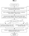
- FIG. 2 is a flowchart illustrating an HDR image processing method according to an embodiment.
- the HDR display device shown in FIG. 1 includes a timing controller 100 having an image processing module 500, a data driver 200 and a gate driver 300 as panel drivers, a display panel 400, the image processing module 500, an illuminance sensor 600, a power supply, a gamma voltage generator, etc.
- the display panel 400 displays an image through a pixel array in which pixels are arranged in a matrix.
- Basic pixels may be composed of at least three subpixels (W/R/G, B/W/R, G/B/W, R/G/B or W/R/G/B) enabling white expression by color mixture of white (W), red (R), green (G) and blue (B) subpixels.
- a liquid crystal display (LCD) panel or an organic light emitting diode (OLED) panel may be used.
- LCD liquid crystal display
- OLED organic light emitting diode
- each subpixel SP includes an OLED element connected between the supply line PL1 of a high voltage EVDD and the supply line PL2 of a low voltage EVSS and a pixel circuit including at least first and second switching TFTs ST1 and ST2, a driving TFT DT and a storage capacitor Cst in order to independently drive the OLED element, as shown in FIG. 1 .
- the configuration of the pixel circuit is various and is not limited to the structure of FIG. 1 .
- the OLED element includes an anode connected to the driving TFT DT, a cathode connected to the supply line PL2 of the low voltage EVSS, and a light emitting layer between the anode and the cathode and emits light in proportion to the amount of current supplied through the driving TFT DT.
- the first switching TFT ST1 is driven by the gate signal of one gate line GLa to supply a data voltage from a data line DL to the gate electrode of the driving TFT DT and the second switching TFT ST2 is driven by the gate signal of another gate line GLb to supply a reference voltage from a reference line RL to the source electrode of the driving TFT DT.
- the second switching TFT ST2 may be further used as a path for outputting current from the driving TFT (DT) to the reference line RL in a sensing mode.
- the storage capacitor Cst connected between the gate electrode and the source electrode of the driving TFT DT supplies a differential voltage between the data voltage supplied to the gate electrode through the first switching TFT ST1 and the reference voltage supplied to the source electrode through the second switching TFT ST2 as driving voltage of the driving TFT DT.
- the driving TFT DT controls current received from the supply line PL1 of the high voltage EVDD according to the driving voltage received from the storage capacitor Cst to supply current proportional to the driving voltage to the OLED element, thereby enabling the OLED element to emit light.
- the data driver 200 receives a data control signal and image data from the timing controller 100.
- the data driver 200 is driven according to the data control signal to divide a reference gamma voltage set received from the gamma voltage generator into gray-level voltages, converts digital image data into analog data signals using the divided gray-level voltages and supplies the analog data signals to the data lines of the display panel 400.
- the data driver 200 includes a plurality of data drive ICs for divisionally driving the data lines of the display panel 400.
- Each data drive IC may be mounted on a circuit film such as a tape carrier package (TCP), a chip on film (COF) or a flexible printed circuit (FPC) to be attached to the display panel 400 using a tape automated bonding (TAB) method or to be mounted on the display panel 400 using a chip on glass (COG) method.
- TCP tape carrier package
- COF chip on film
- FPC flexible printed circuit
- the gate driver 300 drives the plurality of gate lines of the display panel 400 using a gate control signal received from the timing controller 100.
- the gate driver 300 supplies a scan pulse of a gate on voltage to each gate line in a scan period in response to the gate control signal and supplies a gate off voltage in the other period.
- the gate driver 300 may include at least one gate IC and may be mounted on a circuit film such as a TCP, a COF or an FPC to be attached to the display panel 400 using a TAB method or to be mounted on the display panel 400 using a COG method.
- the gate driver 300 may be formed on a TFT substrate along with a TFT array configuring the pixel array of the display panel 400 to be provided in a non-display region of the display panel 400 in a gate-in-panel (GIP) type.
- GIP gate-in-panel
- the illuminance sensor 600 is mounted in the display device to sense the external illuminance of the display device and to supply the sensed illuminance information to the image processing module 500.
- the timing controller 100 receives HDR image data, a timing signal, etc. from an external system.
- the timing controller 100 controls the driving timings of the data driver 200 and the gate driver 300 using the received timing signals.
- the input timing signal includes a dot clock, a data enable signal, a vertical synchronization signal and a horizontal synchronization signal.
- the vertical synchronization signal and the horizontal synchronization signal may be omitted.
- the timing controller 100 may count the data enable signal according to the dot clock to generate and use the vertical synchronization signal and the vertical synchronization signal.
- the data control signals for controlling driving of the data driver 200 may include a source start pulse, a source sampling clock, a source output enable signal, etc.
- the gate control signals for controlling driving of the gate driver 300 may include a gate start pulse, a gate shift clock, a gate output enable signal, etc.
- the timing controller 100 performs a variety of image processing procedures with respect to the HDR image using the image processing module 500 and supplies the image-processed data to the data driver 200.
- the image processing module 500 may be implemented in the timing controller 100 by hardware or may mean a software image processing module stored in a memory. Meanwhile, the image processing module 500 may be provided as a separate IC separately from the timing controller 100. In this case, the image processing module 500 may be located at a previous stage of the timing controller 100.
- the image processing module 500 adjusts a PQ-EOTF according to illuminance to adjust luminance of the HDR image (S2 and S4).
- the image processing module 500 converts the HDR image into luminance information using the PQ-EOTF (S2) and adjusts the luminance information by applying an illuminance-based weight (S4).
- S2 and S4 illuminance-based weight
- the weight increases and thus luminance of the HDR image increases. Therefore, visibility of the HDR image displayed on the display device is improved.
- the image processing module 500 analyzes the HDR image, the luminance of which is adjusted according to illuminance, to calculate a high-luminance rate of occupancy of a high-luminance part having at least a target peak value of the display device in the image (S6).
- the OLED display device implements white with target peak luminance lower than maximum luminance using three-color subpixels (W/R/G, B/W/R, G/B/W or R/G/B) among four-color (W/R/G/B) subpixels in order to adjust a color temperature.
- target peak luminance may be set to 540 nits.
- the image processing module 500 uses a first mapping function in a first luminance part at less than or equal to a target peak value and selectively uses a second mapping function for increasing luminance according to the high-luminance rate of the HDR image in a second luminance part at greater than the target peak, when luminance-mapping the dynamic range of the HDR image to the dynamic range of the display device.
- the image processing module 500 maps the first luminance part at less than or equal to the target peak using the first mapping function and increases the luminance of the second luminance part (high-luminance part) at greater than the target peak value to the maximum luminance (rating value) of the display device using the second non-linear mapping function (S10), when the high-luminance rate of the HDR image exceeds the threshold (S8, Y). Therefore, distinguishability among the gray levels of the high-luminance part may be increased and luminance saturation may be reduced, thereby improving the quality of the HDR image.
- the image processing module 500 maps the first luminance part at less than or equal to the target peakvalue using the first mapping function and clips the luminance of the second luminance part (high-luminance part) at greater than the target peak value to the target peak luminance without using the second mapping function (S12), when the high-luminance rate of the HDR image is less than the threshold. Therefore, the HDR image is displayed with the target peak luminance or less, thereby maintaining power consumption.
- the image processing module 500 converts the luminance information of the HDR image mapped to the dynamic range of the display device into gray level information through the PQ-OETF which is an inverse function of the PQ-EOTF and supplies the gray level information to the data driver 200 (S16).
- the image processing module 500 may further perform an image preprocessing procedure such as conversion of three-color (RGB) data of the HDR image into four-color (WRGB) data before the above-described image processing procedure.
- an image preprocessing procedure such as conversion of three-color (RGB) data of the HDR image into four-color (WRGB) data before the above-described image processing procedure.
- the display device may adjust the luminance of the HDR image according to illuminance and increase the luminance of the high-luminance part when the high-luminance rate of the adjusted HDR image is equal to or greater than the threshold, thereby increasing gray level distinguishability of the HDR image and reducing luminance saturation. Therefore, it is possible to improve visibility and image quality.
- the display device may display the HDR image with the target peak value or less when the high-luminance rate of the HDR image adjusted according to illuminance is less than the threshold, thereby improving visibility and maintaining power consumption.
- FIG. 3 is a block diagram showing an HDR image processing module according to an embodiment.
- FIG. 4 is a graph showing a luminance mapping function according to an embodiment.
- the image processing module 500 shown in FIG. 3 includes an EOTF processor 502, a luminance analyzer 504, a luminance mapping unit 506 and an OETF processor 508.
- the terms "unit” and “-or”/"-er” described in the specification indicate a block for processing at least one function or operation, which may be implemented by hardware or may mean a software image processing module stored in a memory.
- the EOTF processor 502 converts the gray level information of the received HDR image into luminance information using the PQ-EOTF including Equations 1 and 2 below and adjusts the luminance information by applying a weight according to illuminance information received from the illuminance sensor 600.
- N denotes a non-linear color value, which means a value obtained by dividing the color gray level value of each subpixel by a maximum value (e.g., 1,023 in the case of 10 bits) decided by bit-depth and performing normalization with 0 to 1
- L denotes a linear color value in a range of 0 to 1.
- the EOTF processor 502 converts the gray level information of each subpixel into a linear color value L using Equation 1 and scales the linear color value L to absolute luminance C in an HDR range of 0 to 10,000 nits, thereby converting the gray level information of each subpixel into the luminance information.
- the EOTF processor 502 multiplies the luminance information of each subpixel by the weight according to the illuminance information to perform adjustment.
- a look-up table (LUT) having a weight changed according to illuminance section information received from the illuminance sensor 600 is stored in the memory used in the image processing module 500.
- the EOTF processor 502 selects a weight according to the illuminance section information from the LUT, multiplies the luminance information of each subpixel by the selected weight and adjusts the luminance information according to illuminance. As illuminance increases, the weight increases and thus luminance increases. Even when the illuminance is high, visibility is improved.
- the luminance analyzer 504 analyzes the luminance information of the HDR image received from the EOTF processor 502 and calculates the high-luminance rate of occupancy of the high-luminance part having target peak luminance or more of the display device in the HDR image.
- the luminance analyzer 504 analyzes the luminance information of the HDR image at least in frame units and counts the number of high-luminance pixels having target peak luminance or more in the image.
- the luminance analyzer 504 calculates the ratio of the number of high-luminance pixels to the total number of pixels and outputs the high-luminance rate.
- the luminance analyzer 504 may detect a maximum value of the luminance values of the subpixels of each pixel as a representative value of each pixel, compare the representative value of each pixel with the target peak luminance, and count pixels having the representative value equal to or greater than the target peak luminance as high-luminance pixels.
- the luminance mapping unit 506 receives the HDR image and the high-luminance rate from the luminance analyzer 504. The luminance mapping unit 506 maps the luminance information of the HDR image to the dynamic range of the display device according to the high-luminance rate.
- the luminance mapping unit 506 divides the absolute luminance of the HDR image, which is the input luminance Yin before luminance mapping, by the maximum luminance Ymax_display of the display device and performs conversion into normalized luminance (relative luminance) Ypg.
- the luminance mapping unit 506 maps the input luminance Yin corresponding to the normalized luminance Ypq of the HDR image to output luminance Yout corresponding to the normalized luminance Ydisplay of the display device using a mapping function changed according to the high-luminance rate.
- the normalized luminance Ypq of the HDR has a range of 0 to 12.5 and the normalized luminance Ydisplay of the display device has a range of 0 to 1.
- the luminance mapping unit 506 maps the input luminance Yin of the HDR image to the output luminance Yout of the display device using the mapping function shown in FIG. 4 .
- the mapping function includes first and second mapping functions MF1 and MF2 divided according to the target peak luminance Ytp of the display device.
- the luminance mapping unit 506 selectively applies the second mapping function MF2 according to the high-luminance rate.
- the luminance mapping unit 506 maps the input luminance Yin to the output luminance Yout using the first and second mapping function MF1 and MF2 or maps the input luminance Yin to the output luminance Yout using the first mapping function, depending on whether the high-luminance ratio exceeds a threshold TH.
- the luminance mapping unit 506 maps the input luminance Yin of the subpixels exceeding the target peak luminance Ytp to the target peak luminance Ytp of the display device. Therefore, the luminance values having the target peak of the HDR image is displayed in a state of being clipped to the target peak luminance of the display device, thereby maintaining power consumption.
- the luminance mapping unit 506 maps the input luminance Yin to the output luminance Yout using the first and second mapping functions MF1 and MF2.
- the luminance mapping unit 506 maps the input luminance Yin of the subpixel belonging to the high-luminance part between the target peak luminance Ytp and the maximum luminance Ymax to the output luminance Yout which gradually increases in a range between the target peak luminance Ytp of the display device and the maximum luminance Ymax using the second non-linear mapping function MF2. Therefore, the luminance of the HDR image is increased such that the gray levels are distinguishable without saturation of the high-luminance part between the target peak luminance Ytp and the maximum luminance Ymax, thereby improving the quality of the HDR image.
- the second non-linear mapping function MF2 shown in FIG. 4 may be defined as shown in Equation 3 below.
- Equation 3 Ytp denotes normalized target peak luminance of the display device, Ycp denotes normalized clipping luminance of the input luminance Yin, b is a constant. As the b value decreases, a curve becomes gradual. Therefore, the b value is set to a value capable of obtaining a natural curve through experimentation.
- the clipping luminance Ycp of the input luminance Yin is obtained by dividing the maximum luminance of the HDR image by the maximum luminance of the display device and performing normalization.
- the maximum luminance of the HDR image is 10000 nits.
- the clipping luminance Ycp of the input luminance Yin may be set to the maximum luminance Ymax of the display device.
- the clipping luminance Ycp or the input luminance Yin greater than the maximum luminance Ymax is mapped to the maximum luminance Ymax of the display device.
- the OETF processor 508 converts the luminance information Yout of each subpixel received from the luminance mapping unit 506 into the gray level information using the PQ-OETF which is the inverse function of the PQ-EOTF and then outputs the gray level information.
- FIG. 5 is a diagram showing an image processing result of an HDR display device according to an embodiment using a PQ-EOTF curve.
- the HDR display device may display the output luminance of the input gray level along the basic PQ-EOTF curve and represent the gray level up to the target peak luminance of the display device.
- the PQ-EOTF curve is shifted to the left.
- the output luminance according to the gray level increases as compared to the basic PQ-EOTF curve.
- the target peak luminance gradually increases from the target peak luminance to the maximum luminance along a roll-off curve without saturation of the high gray level part corresponding to high luminance equal to or greater than the target peak luminance, thereby increasing distinguishability of the gray level of the HDR image and reducing luminance saturation.
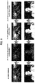
- FIG. 6 is a diagram showing an image processing result when an HDR display device according to an embodiment displays an HDR image having a high-luminance rate greater than a threshold.
- the high-luminance rate (2% or 27%) of occupancy of pixels exceeding the target peak luminance (540 nits) of the display device in the image exceeds the threshold TH (1.5%), as a result d of performing the image processing procedure of increasing the luminance of the high-luminance (high gray level) part from the target peak luminance of the display device to the maximum luminance, visibility is improved and gray-level banding is reduced, thereby improving image quality.
- FIG. 7 is a diagram showing image processing effects when an HDR display device according to an embodiment displays an HDR image having a high-luminance rate less than a threshold.
- the HDR display device if an original HDR image a is displayed in a bright outdoor environment without applying the illuminance-based weight (b), visibility is deteriorated but, as a result (c) of adjusting the PQ-EOTF curve by applying the illuminance-based weight, visibility in the bright outdoor environment is improved. Since the high-luminance rate (0.5%) of the image is less than the threshold TH (1.5%), the image processing procedure of increasing luminance is not performed.
- the PQ-EOTF curve is adjusted according to illuminance to adjust the luminance of the HDR image, and, if the high-luminance rate of the adjusted HDR image is equal to or greater than the threshold, the luminance of the high-luminance part equal to or greater than the target peak luminance of the display device increases to increase gray-level distinguishability of the HDR image and to reduce luminance saturation, thereby improving visibility and image quality.
- the display device displays the HDR image with luminance equal to or less than the target peak luminance of the display device if the high-luminance rate of the HDR image adjusted according to illuminance is less than the threshold, thereby improving visibility and maintaining power consumption.
Landscapes
- Engineering & Computer Science (AREA)
- Multimedia (AREA)
- Signal Processing (AREA)
- Physics & Mathematics (AREA)
- General Physics & Mathematics (AREA)
- Theoretical Computer Science (AREA)
- Computer Hardware Design (AREA)
- Computer Vision & Pattern Recognition (AREA)
- Control Of Indicators Other Than Cathode Ray Tubes (AREA)
Abstract
Description
- The present disclosure relates to a method and module for processing a high dynamic range (HDR) image, which are capable of improving visibility according to illuminance, and a display device using the same.
- Human beings can perceive a wide brightness range of about 10-6 to 108 nits (cd/m2) and high dynamic range (hereinafter, HDR) technology considering the same has extended to image creation, display development, etc. in addition to photography.
- An HDR image is encoded using a perceptual quantizer opto-electrical transfer function (hereinafter, PQ-OETF) defined by the society of motion picture and television engineers (SMPTE) ST. 2084 and has a high dynamic range of 0 to 10,000 nits.
- A display device needs to perform an image processing procedure using a perceptual quantizer electro-optical transfer function (PQ-EOTF) defined in SMPTE ST. 2084, in order to display an HDR image.
- However, since the PQ-EOTF used in the image processing procedure of the display device is derived in a dark room, a just-noticeable difference (JND) in a bright room is not applied.
- To this end, when the display device displays an HDR image subjected to the image processing procedure using the PQ-EOTF in a bright room, a luminance saturation phenomenon wherein gray-level banding is caused in a high luminance region of an image is generated, deteriorating visibility.
- Accordingly, disclosed embodiments are directed to a method and module for processing a high dynamic range (HDR) image and a display device using the same and that substantially address one or more problems due to limitations and disadvantages of the related art.
- Disclosed embodiments provide a method and module for processing a high dynamic range (HDR) image, which are capable of adaptively improving visibility of the HDR image according to illuminance, and a display device using the same.
- Additional advantages, objects, and features of the embodiments will be set forth in part in the description which follows and in part will become apparent to those having ordinary skill in the art upon examination of the following. The objectives and other advantages may be realized and attained by the structure particularly pointed out in the written description and claims hereof as well as the appended drawings.
- In the method and module for processing the image according to one embodiment, illuminance information sensed through an illuminance sensor is received, a perceptual quantizer electro-optical transfer function (PQ-EOTF) is adjusted, and gray level information of a first HDR image is converted into luminance information of a second HDR image using the adjusted PQ-EOTF.
- In the method and module for processing the image according to one embodiment, the luminance information of the second HDR image is analyzed to calculate a high-luminance rate of occupancy of pixels having target peak luminance or more of a display device in the second HDR image.
- In the method and module for processing the image according to one embodiment, the second HDR image is luminance-mapped to a third HDR image suitable for the display device using a mapping function changed according to the high-luminance rate.
- In the method and module for processing the image according to one embodiment, luminance information of the third HDR image is converted into gray level information of a fourth HDR image using a perceptual quantizer opto-electrical transfer function (PQ-OETF) and the gray level information is output.
- In the method and module for processing the image according to one embodiment, when the high-luminance rate exceeds a threshold, a first linear mapping function is used in a first luminance part having the target peak luminance or less of the second HDR image and a second non-linear mapping function is used in a second luminance part having the target peak luminance or more, and, when the high-luminance rate is equal to or less than the threshold, the first mapping function is used.
- In the method and module for processing the image according to one embodiment, when the high-luminance rate exceeds the threshold, luminance of the second luminance part of the second HDR image increases according to the second mapping function in a range between the target peak luminance of the display device and a maximum luminance of the display device, and, when the high-luminance rate is equal to or less than the threshold, the second luminance part of the second HDR image is mapped to the target peak luminance.
- A display device of one embodiment uses the above-described image processing module.
- In the embodiment disclosed, the PQ-EOTF curve is adjusted according to illuminance to adjust the luminance of the HDR image, and, if the high-luminance rate of the adjusted HDR image is equal to or greater than the threshold, the luminance of the high-luminance part equal to or greater than the target peak luminance of the display device increases to increase gray-level distinguishability of the HDR image and to reduce luminance saturation, thereby improving visibility and image quality.
- The display device according to the embodiment may display the HDR image with luminance equal to or less than the target peak luminance of the display device if the high-luminance rate of the HDR image adjusted according to illuminance is less than the threshold, thereby improving visibility and maintaining power consumption.
- It is to be understood that both the foregoing general description and the following detailed description are exemplary and explanatory.
- The accompanying drawings are incorporated in and constitute a part of this application and illustrate and disclose embodiment(s).
-
FIG. 1 is a schematic block diagram showing the configuration of an HDR display device according to an embodiment. -
FIG. 2 is a flowchart illustrating an HDR image processing method according to an embodiment. -
FIG. 3 is a block diagram showing an HDR image processing module according to an embodiment. -
FIG. 4 is a graph showing a luminance mapping function according to an embodiment. -
FIG. 5 is a diagram showing an image processing result of an HDR display device according to an embodiment using a PQ-EOTF curve. -
FIG. 6 is a diagram showing an image processing result when an HDR display device according to an embodiment displays an HDR image having a high-luminance rate greater than a threshold. -
FIG. 7 is a diagram showing image processing effects when an HDR display device according to an embodiment displays an HDR image having a high-luminance rate less than a threshold. -
FIG. 1 is a schematic block diagram showing the configuration of an HDR display device according to an embodiment.FIG. 2 is a flowchart illustrating an HDR image processing method according to an embodiment. - The HDR display device shown in
FIG. 1 includes atiming controller 100 having animage processing module 500, adata driver 200 and agate driver 300 as panel drivers, adisplay panel 400, theimage processing module 500, anilluminance sensor 600, a power supply, a gamma voltage generator, etc. - The
display panel 400 displays an image through a pixel array in which pixels are arranged in a matrix. Basic pixels may be composed of at least three subpixels (W/R/G, B/W/R, G/B/W, R/G/B or W/R/G/B) enabling white expression by color mixture of white (W), red (R), green (G) and blue (B) subpixels. - As the
display panel 400, a liquid crystal display (LCD) panel or an organic light emitting diode (OLED) panel may be used. Hereinafter, assume that thedisplay panel 400 is an OLED panel. - If the
display panel 400 is an OLED panel, each subpixel SP includes an OLED element connected between the supply line PL1 of a high voltage EVDD and the supply line PL2 of a low voltage EVSS and a pixel circuit including at least first and second switching TFTs ST1 and ST2, a driving TFT DT and a storage capacitor Cst in order to independently drive the OLED element, as shown inFIG. 1 . The configuration of the pixel circuit is various and is not limited to the structure ofFIG. 1 . - The OLED element includes an anode connected to the driving TFT DT, a cathode connected to the supply line PL2 of the low voltage EVSS, and a light emitting layer between the anode and the cathode and emits light in proportion to the amount of current supplied through the driving TFT DT.
- The first switching TFT ST1 is driven by the gate signal of one gate line GLa to supply a data voltage from a data line DL to the gate electrode of the driving TFT DT and the second switching TFT ST2 is driven by the gate signal of another gate line GLb to supply a reference voltage from a reference line RL to the source electrode of the driving TFT DT. The second switching TFT ST2 may be further used as a path for outputting current from the driving TFT (DT) to the reference line RL in a sensing mode.
- The storage capacitor Cst connected between the gate electrode and the source electrode of the driving TFT DT supplies a differential voltage between the data voltage supplied to the gate electrode through the first switching TFT ST1 and the reference voltage supplied to the source electrode through the second switching TFT ST2 as driving voltage of the driving TFT DT.
- The driving TFT DT controls current received from the supply line PL1 of the high voltage EVDD according to the driving voltage received from the storage capacitor Cst to supply current proportional to the driving voltage to the OLED element, thereby enabling the OLED element to emit light.
- The
data driver 200 receives a data control signal and image data from thetiming controller 100. Thedata driver 200 is driven according to the data control signal to divide a reference gamma voltage set received from the gamma voltage generator into gray-level voltages, converts digital image data into analog data signals using the divided gray-level voltages and supplies the analog data signals to the data lines of thedisplay panel 400. - The
data driver 200 includes a plurality of data drive ICs for divisionally driving the data lines of thedisplay panel 400. Each data drive IC may be mounted on a circuit film such as a tape carrier package (TCP), a chip on film (COF) or a flexible printed circuit (FPC) to be attached to thedisplay panel 400 using a tape automated bonding (TAB) method or to be mounted on thedisplay panel 400 using a chip on glass (COG) method. - The
gate driver 300 drives the plurality of gate lines of thedisplay panel 400 using a gate control signal received from thetiming controller 100. Thegate driver 300 supplies a scan pulse of a gate on voltage to each gate line in a scan period in response to the gate control signal and supplies a gate off voltage in the other period. - The
gate driver 300 may include at least one gate IC and may be mounted on a circuit film such as a TCP, a COF or an FPC to be attached to thedisplay panel 400 using a TAB method or to be mounted on thedisplay panel 400 using a COG method. Alternatively, thegate driver 300 may be formed on a TFT substrate along with a TFT array configuring the pixel array of thedisplay panel 400 to be provided in a non-display region of thedisplay panel 400 in a gate-in-panel (GIP) type. - The
illuminance sensor 600 is mounted in the display device to sense the external illuminance of the display device and to supply the sensed illuminance information to theimage processing module 500. - The
timing controller 100 receives HDR image data, a timing signal, etc. from an external system. Thetiming controller 100 controls the driving timings of thedata driver 200 and thegate driver 300 using the received timing signals. The input timing signal includes a dot clock, a data enable signal, a vertical synchronization signal and a horizontal synchronization signal. The vertical synchronization signal and the horizontal synchronization signal may be omitted. In this case, thetiming controller 100 may count the data enable signal according to the dot clock to generate and use the vertical synchronization signal and the vertical synchronization signal. The data control signals for controlling driving of thedata driver 200 may include a source start pulse, a source sampling clock, a source output enable signal, etc. The gate control signals for controlling driving of thegate driver 300 may include a gate start pulse, a gate shift clock, a gate output enable signal, etc. - The
timing controller 100 performs a variety of image processing procedures with respect to the HDR image using theimage processing module 500 and supplies the image-processed data to thedata driver 200. Theimage processing module 500 may be implemented in thetiming controller 100 by hardware or may mean a software image processing module stored in a memory. Meanwhile, theimage processing module 500 may be provided as a separate IC separately from thetiming controller 100. In this case, theimage processing module 500 may be located at a previous stage of thetiming controller 100. - Hereinafter, the image processing method of the
image processing module 500 will be described with reference toFIGs. 1 and2 . - The
image processing module 500 adjusts a PQ-EOTF according to illuminance to adjust luminance of the HDR image (S2 and S4). In other words, theimage processing module 500 converts the HDR image into luminance information using the PQ-EOTF (S2) and adjusts the luminance information by applying an illuminance-based weight (S4). As illuminance increases, the weight increases and thus luminance of the HDR image increases. Therefore, visibility of the HDR image displayed on the display device is improved. - The
image processing module 500 analyzes the HDR image, the luminance of which is adjusted according to illuminance, to calculate a high-luminance rate of occupancy of a high-luminance part having at least a target peak value of the display device in the image (S6). - In general, the OLED display device implements white with target peak luminance lower than maximum luminance using three-color subpixels (W/R/G, B/W/R, G/B/W or R/G/B) among four-color (W/R/G/B) subpixels in order to adjust a color temperature. For example, when the maximum luminance (rating value) of the OLED display device is 800 nits, target peak luminance may be set to 540 nits.
- The
image processing module 500 uses a first mapping function in a first luminance part at less than or equal to a target peak value and selectively uses a second mapping function for increasing luminance according to the high-luminance rate of the HDR image in a second luminance part at greater than the target peak, when luminance-mapping the dynamic range of the HDR image to the dynamic range of the display device. - More specifically, the
image processing module 500 maps the first luminance part at less than or equal to the target peak using the first mapping function and increases the luminance of the second luminance part (high-luminance part) at greater than the target peak value to the maximum luminance (rating value) of the display device using the second non-linear mapping function (S10), when the high-luminance rate of the HDR image exceeds the threshold (S8, Y). Therefore, distinguishability among the gray levels of the high-luminance part may be increased and luminance saturation may be reduced, thereby improving the quality of the HDR image. - In contrast, the
image processing module 500 maps the first luminance part at less than or equal to the target peakvalue using the first mapping function and clips the luminance of the second luminance part (high-luminance part) at greater than the target peak value to the target peak luminance without using the second mapping function (S12), when the high-luminance rate of the HDR image is less than the threshold. Therefore, the HDR image is displayed with the target peak luminance or less, thereby maintaining power consumption. - The
image processing module 500 converts the luminance information of the HDR image mapped to the dynamic range of the display device into gray level information through the PQ-OETF which is an inverse function of the PQ-EOTF and supplies the gray level information to the data driver 200 (S16). - The
image processing module 500 may further perform an image preprocessing procedure such as conversion of three-color (RGB) data of the HDR image into four-color (WRGB) data before the above-described image processing procedure. - The display device according to the embodiment may adjust the luminance of the HDR image according to illuminance and increase the luminance of the high-luminance part when the high-luminance rate of the adjusted HDR image is equal to or greater than the threshold, thereby increasing gray level distinguishability of the HDR image and reducing luminance saturation. Therefore, it is possible to improve visibility and image quality. The display device according to the embodiment may display the HDR image with the target peak value or less when the high-luminance rate of the HDR image adjusted according to illuminance is less than the threshold, thereby improving visibility and maintaining power consumption.
-
FIG. 3 is a block diagram showing an HDR image processing module according to an embodiment.FIG. 4 is a graph showing a luminance mapping function according to an embodiment. - The
image processing module 500 shown inFIG. 3 includes anEOTF processor 502, aluminance analyzer 504, aluminance mapping unit 506 and anOETF processor 508. The terms "unit" and "-or"/"-er" described in the specification indicate a block for processing at least one function or operation, which may be implemented by hardware or may mean a software image processing module stored in a memory. - The
EOTF processor 502 converts the gray level information of the received HDR image into luminance information using the PQ-EOTF including Equations 1 and 2 below and adjusts the luminance information by applying a weight according to illuminance information received from theilluminance sensor 600.

- In Equation 1, N denotes a non-linear color value, which means a value obtained by dividing the color gray level value of each subpixel by a maximum value (e.g., 1,023 in the case of 10 bits) decided by bit-depth and performing normalization with 0 to 1, and L denotes a linear color value in a range of 0 to 1. m1 to m2 and c1 to c3 are constants. For example, m1=(2610/4096)×(1/4)=0.1593017578125, m2=(2523/4096)×128=78.84375, c1=3424/4096=0.8359375=c3-c2+1, c2=(2413/4096)×32=18.8515625, and c3=(2392/4096)×32=18.6875.
- The
EOTF processor 502 converts the gray level information of each subpixel into a linear color value L using Equation 1 and scales the linear color value L to absolute luminance C in an HDR range of 0 to 10,000 nits, thereby converting the gray level information of each subpixel into the luminance information. - The
EOTF processor 502 multiplies the luminance information of each subpixel by the weight according to the illuminance information to perform adjustment. A look-up table (LUT) having a weight changed according to illuminance section information received from theilluminance sensor 600 is stored in the memory used in theimage processing module 500. TheEOTF processor 502 selects a weight according to the illuminance section information from the LUT, multiplies the luminance information of each subpixel by the selected weight and adjusts the luminance information according to illuminance. As illuminance increases, the weight increases and thus luminance increases. Even when the illuminance is high, visibility is improved. - The
luminance analyzer 504 analyzes the luminance information of the HDR image received from theEOTF processor 502 and calculates the high-luminance rate of occupancy of the high-luminance part having target peak luminance or more of the display device in the HDR image. Theluminance analyzer 504 analyzes the luminance information of the HDR image at least in frame units and counts the number of high-luminance pixels having target peak luminance or more in the image. Theluminance analyzer 504 calculates the ratio of the number of high-luminance pixels to the total number of pixels and outputs the high-luminance rate. Theluminance analyzer 504 may detect a maximum value of the luminance values of the subpixels of each pixel as a representative value of each pixel, compare the representative value of each pixel with the target peak luminance, and count pixels having the representative value equal to or greater than the target peak luminance as high-luminance pixels. - The
luminance mapping unit 506 receives the HDR image and the high-luminance rate from theluminance analyzer 504. Theluminance mapping unit 506 maps the luminance information of the HDR image to the dynamic range of the display device according to the high-luminance rate. - More specifically, the
luminance mapping unit 506 divides the absolute luminance of the HDR image, which is the input luminance Yin before luminance mapping, by the maximum luminance Ymax_display of the display device and performs conversion into normalized luminance (relative luminance) Ypg. Theluminance mapping unit 506 maps the input luminance Yin corresponding to the normalized luminance Ypq of the HDR image to output luminance Yout corresponding to the normalized luminance Ydisplay of the display device using a mapping function changed according to the high-luminance rate. For example, if the maximum luminance of the display device is 800 nits, the normalized luminance Ypq of the HDR has a range of 0 to 12.5 and the normalized luminance Ydisplay of the display device has a range of 0 to 1. - The
luminance mapping unit 506 maps the input luminance Yin of the HDR image to the output luminance Yout of the display device using the mapping function shown inFIG. 4 . The mapping function includes first and second mapping functions MF1 and MF2 divided according to the target peak luminance Ytp of the display device. Theluminance mapping unit 506 selectively applies the second mapping function MF2 according to the high-luminance rate. - For example, if the maximum luminance of the display device is 800 nits and the target peak is 540 nits, in the mapping function shown in
FIG. 4 , the target peak point Ytp may become 540/800=0.675. - The
luminance mapping unit 506 maps the input luminance Yin to the output luminance Yout using the first and second mapping function MF1 and MF2 or maps the input luminance Yin to the output luminance Yout using the first mapping function, depending on whether the high-luminance ratio exceeds a threshold TH. - If the high-luminance rate of the HDR image is equal to or less than the threshold TH, the
luminance mapping unit 506 maps the input luminance Yin to the output luminance Yout using the first mapping function (MF1: Yout=kYin). If the gradient k is set to 1 in the first mapping function MF1, the output luminance Yout of the display device, to which the input luminance Yin of the subpixel belonging to the target peak luminance Ytp or less is mapped, may be equal to the input luminance Yin. Theluminance mapping unit 506 maps the input luminance Yin of the subpixels exceeding the target peak luminance Ytp to the target peak luminance Ytp of the display device. Therefore, the luminance values having the target peak of the HDR image is displayed in a state of being clipped to the target peak luminance of the display device, thereby maintaining power consumption. - If the high-luminance rate of the HDR image exceeds the threshold TH, the
luminance mapping unit 506 maps the input luminance Yin to the output luminance Yout using the first and second mapping functions MF1 and MF2. Theluminance mapping unit 506 maps the input luminance Yin of the subpixel belonging to the target peak luminance Ytp or less to the output luminance Yout using the first linear mapping function MF1 (Yout=kYin), as described above. - The
luminance mapping unit 506 maps the input luminance Yin of the subpixel belonging to the high-luminance part between the target peak luminance Ytp and the maximum luminance Ymax to the output luminance Yout which gradually increases in a range between the target peak luminance Ytp of the display device and the maximum luminance Ymax using the second non-linear mapping function MF2. Therefore, the luminance of the HDR image is increased such that the gray levels are distinguishable without saturation of the high-luminance part between the target peak luminance Ytp and the maximum luminance Ymax, thereby improving the quality of the HDR image. - The second non-linear mapping function MF2 shown in
FIG. 4 may be defined as shown in Equation 3 below.
- In Equation 3, Ytp denotes normalized target peak luminance of the display device, Ycp denotes normalized clipping luminance of the input luminance Yin, b is a constant. As the b value decreases, a curve becomes gradual. Therefore, the b value is set to a value capable of obtaining a natural curve through experimentation. The clipping luminance Ycp of the input luminance Yin is obtained by dividing the maximum luminance of the HDR image by the maximum luminance of the display device and performing normalization. The maximum luminance of the HDR image is 10000 nits. In consideration of the luminance limit of the display device, when dividing 4,000 nits which are generally used upon mastering of a content creation company by the maximum luminance (e.g., 800 nits) of the display device and performing normalization, the clipping luminance Ycp may be set to 4,000/800=5. The clipping luminance Ycp of the input luminance Yin may be set to the maximum luminance Ymax of the display device. The clipping luminance Ycp or the input luminance Yin greater than the maximum luminance Ymax is mapped to the maximum luminance Ymax of the display device.
- The
OETF processor 508 converts the luminance information Yout of each subpixel received from theluminance mapping unit 506 into the gray level information using the PQ-OETF which is the inverse function of the PQ-EOTF and then outputs the gray level information. -
FIG. 5 is a diagram showing an image processing result of an HDR display device according to an embodiment using a PQ-EOTF curve. - Referring to
FIG. 5 , the HDR display device may display the output luminance of the input gray level along the basic PQ-EOTF curve and represent the gray level up to the target peak luminance of the display device. In the case of applying the illuminance-based weight to adjust the PQ-EOTF curve, as the illuminance-based weight increases, the PQ-EOTF curve is shifted to the left. In the PQ-EOTF1 curve shifted based on the illuminance-based weight, it can be seen that the output luminance according to the gray level increases as compared to the basic PQ-EOTF curve. If the high-luminance rate of occupancy of the pixels exceeding the target peak luminance (e.g., 540 nits) of the display device in the HDR image exceeds the threshold TH, the target peak luminance gradually increases from the target peak luminance to the maximum luminance along a roll-off curve without saturation of the high gray level part corresponding to high luminance equal to or greater than the target peak luminance, thereby increasing distinguishability of the gray level of the HDR image and reducing luminance saturation. -
FIG. 6 is a diagram showing an image processing result when an HDR display device according to an embodiment displays an HDR image having a high-luminance rate greater than a threshold. - Referring to
FIG. 6 , in the HDR display device according to the embodiment, if an original HDR image a is displayed in a bright outdoor environment without applying the illuminance-based weight (b), visibility is deteriorated but, as a result (c) of adjusting the PQ-EOTF curve by applying the illuminance-based weight, visibility in the bright outdoor environment is improved. In addition, since the high-luminance rate (2% or 27%) of occupancy of pixels exceeding the target peak luminance (540 nits) of the display device in the image exceeds the threshold TH (1.5%), as a result d of performing the image processing procedure of increasing the luminance of the high-luminance (high gray level) part from the target peak luminance of the display device to the maximum luminance, visibility is improved and gray-level banding is reduced, thereby improving image quality. -
FIG. 7 is a diagram showing image processing effects when an HDR display device according to an embodiment displays an HDR image having a high-luminance rate less than a threshold. - Referring to
FIG. 7 , in the HDR display device according to the embodiment, if an original HDR image a is displayed in a bright outdoor environment without applying the illuminance-based weight (b), visibility is deteriorated but, as a result (c) of adjusting the PQ-EOTF curve by applying the illuminance-based weight, visibility in the bright outdoor environment is improved. Since the high-luminance rate (0.5%) of the image is less than the threshold TH (1.5%), the image processing procedure of increasing luminance is not performed. - In the embodiment, the PQ-EOTF curve is adjusted according to illuminance to adjust the luminance of the HDR image, and, if the high-luminance rate of the adjusted HDR image is equal to or greater than the threshold, the luminance of the high-luminance part equal to or greater than the target peak luminance of the display device increases to increase gray-level distinguishability of the HDR image and to reduce luminance saturation, thereby improving visibility and image quality.
- The display device according to the embodiment displays the HDR image with luminance equal to or less than the target peak luminance of the display device if the high-luminance rate of the HDR image adjusted according to illuminance is less than the threshold, thereby improving visibility and maintaining power consumption.
- Those skilled in the art will appreciate that various modifications and applications are possible, without departing from the scope of the invention as disclosed in the accompanying claims.
- Further embodiments are defined in the following numbered clauses:
- 1. An image processing method comprising: receiving illuminance information sensed through an illuminance sensor; adjusting a perceptual quantizer electro-optical transfer function (PQ-EOTF) according to the illuminance information and converting gray level information of a first HDR image into luminance information of a second HDR image using the adjusted PQ-EOTF; analyzing the luminance information of the second HDR image and calculating a high-luminance rate of occupancy of pixels having target peak luminance or more of a display device in the second HDR image; luminance-mapping the second HDR image to a third HDR image suitable for the display device using a mapping function changed according to the high-luminance rate; and converting luminance information of the third HDR image into gray level information of a fourth HDR image using a perceptual quantizer opto-electrical transfer function (PQ-OETF) and outputting the gray level information.
- 2. The method according to clause 1, wherein, in the luminance-mapping, when the high-luminance rate exceeds a threshold, a first linear mapping function is used in a first luminance part having the target peak luminance or less of the second HDR image and a second non-linear mapping function is used in a second luminance part having the target peak luminance or more, and when the high-luminance rate is equal to or less than the threshold, the first mapping function is used.
- 3. The method according to
clause 2, wherein: when the high-luminance rate exceeds the threshold, luminance of the second luminance part of the second HDR image increases according to the second mapping function in a range between the target peak luminance of the display device and a maximum luminance of the display device, and when the high-luminance rate is equal to or less than the threshold, the second luminance part of the second HDR image is mapped to the target peak luminance. - 4. An image processing module comprising: an electro-optical transfer function (EOTF) processor configured to receive illuminance information sensed by an illuminance sensor to adjust a perceptual quantizer electro-optical transfer function (PQ-EOTF) and to convert gray level information of a first HDR image into luminance information of a second HDR image using the adjusted PQ-EOTF; a luminance analyzer configured to analyze the luminance information of the second HDR image to calculate a high-luminance rate of occupancy of pixels having target peak luminance or more of a display device in the second HDR image; a luminance mapping unit configured to map the second HDR image to a third HDR image suitable for the display device using a mapping function changed according to the high-luminance rate; and an opto-electrical transfer function (OETF) processor configured to convert the luminance information of the third HDR image into gray level information of a fourth HDR image using the PQ-OETF and to output the gray level information.
- 5. The image processing module according to clause 4, wherein the luminance mapping unit: uses a first linear mapping function in a first luminance part having the target peak luminance or less of the second HDR image and uses a second non-linear mapping function in a second luminance part having the target peak luminance or more, when the high-luminance rate exceeds a threshold, and uses the first mapping function when the high-luminance rate is equal to or less than the threshold.
- 6. The image processing module according to clause 5, wherein the luminance mapping unit: increases luminance of the second luminance part of the second HDR image according to the second mapping function in a range between the target peak luminance of the display device and a maximum luminance of the display device, when the high-luminance rate exceeds the threshold, and maps the second luminance part of the second HDR image to the target peak luminance when the high-luminance rate is equal to or less than the threshold.
- 7. The image processing module according to clause 5, wherein the luminance mapping unit: performs conversion into input luminance normalized by dividing the luminance information of the second HDR image by maximum luminance of the display device before luminance-mapping the second HDR image to the third HDR image, and maps the input luminance to normalized output luminance of the display device using the first or second mapping function.
- 8. A display device comprising: a display panel; the image processing module; and a display panel driver configured to drive the display panel to display an HDR image received from the image processing module, wherein the image processing module comprises: an electro-optical transfer function (EOTF) processor configured to receive illuminance information sensed by an illuminance sensor to adjust a perceptual quantizer electro-optical transfer function (PQ-EOTF) and to convert gray level information of a first HDR image into luminance information of a second HDR image using the adjusted PQ-EOTF; a luminance analyzer configured to analyze the luminance information of the second HDR image to calculate a high-luminance rate of occupancy of pixels having target peak luminance or more of a display device in the second HDR image; a luminance mapping unit configured to map the second HDR image to a third HDR image suitable for the display device using a mapping function changed according to the high-luminance rate; and an opto-electrical transfer function (OETF) processor configured to convert the luminance information of the third HDR image into gray level information of a fourth HDR image using the PQ-OETF and to output the gray level information.
- 9. The display device according to clause 8, wherein the luminance mapping unit: uses a first linear mapping function in a first luminance part having the target peak luminance or less of the second HDR image and uses a second non-linear mapping function in a second luminance part having the target peak luminance or more, when the high-luminance rate exceeds a threshold, and uses the first mapping function when the high-luminance rate is equal to or less than the threshold.
- 10. The display device according to clause 9, wherein the luminance mapping unit: increases luminance of the second luminance part of the second HDR image according to the second mapping function in a range between the target peak luminance of the display device and a maximum luminance of the display device, when the high-luminance rate exceeds the threshold, and maps the second luminance part of the second HDR image to the target peak luminance when the high-luminance rate is equal to or less than the threshold.
- 11. The display device according to clause 9, wherein the luminance mapping unit: performs conversion into input luminance normalized by dividing the luminance information of the second HDR image by maximum luminance of the display device before luminance-mapping the second HDR image to the third HDR image, and maps the input luminance to normalized output luminance of the display device using the first or second mapping function.
Claims (8)
- An image processing method comprising:receiving illuminance information sensed through an illuminance sensor (600);adjusting (502) a perceptual quantizer electro-optical transfer function (PQ-EOTF) according to the illuminance information and converting gray level information of a first HDR image into luminance information of a second HDR image using the adjusted PQ-EOTF;analyzing (504) the luminance information of the second HDR image and calculating a high-luminance rate of occupancy of pixels having at least a target peak luminance (Ytp) of a display device in the second HDR image;luminance-mapping (506) the second HDR image to a third HDR image suitable for the display device using a mapping function changed according to the high-luminance rate; andconverting (508) luminance information of the third HDR image into gray level information of a fourth HDR image using a perceptual quantizer opto-electrical transfer function (PQ-OETF) and outputting the gray level information.
- The method according to claim 1, wherein, in the luminance-mapping,
when the high-luminance rate exceeds a threshold, a first linear mapping function is used below or at a target peak luminance of a first luminance part of the second HDR image and a second non-linear mapping function is used in a second luminance part above a target peak luminance, and
when the high-luminance rate is equal to or less than the threshold, the first mapping function is used. - The method according to claim 2, wherein:when the high-luminance rate exceeds the threshold, luminance of the second luminance part of the second HDR image increases according to the second mapping function in a range between the target peak luminance of the display device and a maximum luminance of the display device, andwhen the high-luminance rate is equal to or less than the threshold, the second luminance part of the second HDR image is mapped to the target peak luminance.
- An image processing module (500) comprising:an electro-optical transfer function (EOTF) processor (502) configured to receive illuminance information sensed by an illuminance sensor (600) to adjust a perceptual quantizer electro-optical transfer function (PQ-EOTF) and to convert gray level information of a first HDR image into luminance information of a second HDR image using the adjusted PQ-EOTF;a luminance analyzer (504) configured to analyze the luminance information of the second HDR image to calculate a high-luminance rate of occupancy of pixels having target peak luminance or more of a display device in the second HDR image;a luminance mapping unit (506) configured to map the second HDR image to a third HDR image suitable for the display device using a mapping function changed according to the high-luminance rate; andan opto-electrical transfer function (OETF) processor (506) configured to convert the luminance information of the third HDR image into gray level information of a fourth HDR image using the PQ-OETF and to output the gray level information.
- The image processing module (500) according to claim 4,
wherein the luminance mapping unit (506):uses a first linear mapping function in a first luminance part below or at the target peak luminance of the second HDR image and uses a second non-linear mapping function in a second luminance part above the target peak luminance, when the high-luminance rate exceeds a threshold, anduses the first mapping function when the high-luminance rate is equal to or less than the threshold. - The image processing module (500) according to claim 5, wherein the luminance mapping unit (506):increases luminance of the second luminance part of the second HDR image according to the second mapping function in a range between the target peak luminance of the display device and a maximum luminance of the display device, when the high-luminance rate exceeds the threshold, andmaps the second luminance part of the second HDR image to the target peak luminance when the high-luminance rate is equal to or less than the threshold.
- The image processing module (500) according to claim 5,
wherein the luminance mapping unit (506):performs conversion into input luminance normalized by dividing the luminance information of the second HDR image by the maximum luminance of the display device before luminance-mapping the second HDR image to the third HDR image, andmaps the input luminance to normalized output luminance of the display device using the first or second mapping function. - A display device comprising:a display panel (400);the image processing module (500) as claimed in any of claims 4 to 7; anda display panel driver configured to drive the display panel to display an HDR image received from the image processing module (500).
Applications Claiming Priority (1)
| Application Number | Priority Date | Filing Date | Title |
|---|---|---|---|
| KR1020160143894A KR102554379B1 (en) | 2016-10-31 | 2016-10-31 | Image processing method and module for high dynamic range (hdr) and display device using the same |
Publications (2)
| Publication Number | Publication Date |
|---|---|
| EP3316238A1 true EP3316238A1 (en) | 2018-05-02 |
| EP3316238B1 EP3316238B1 (en) | 2022-06-22 |
Family
ID=60162055
Family Applications (1)
| Application Number | Title | Priority Date | Filing Date |
|---|---|---|---|
| EP17197793.7A Active EP3316238B1 (en) | 2016-10-31 | 2017-10-23 | Method and module for processing high dynamic range (hdr) image and display device using the same |
Country Status (5)
| Country | Link |
|---|---|
| US (1) | US10504217B2 (en) |
| EP (1) | EP3316238B1 (en) |
| KR (1) | KR102554379B1 (en) |
| CN (1) | CN108009993B (en) |
| TW (1) | TWI651700B (en) |
Cited By (1)
| Publication number | Priority date | Publication date | Assignee | Title |
|---|---|---|---|---|
| CN110689861A (en) * | 2019-09-29 | 2020-01-14 | 联想(北京)有限公司 | Brightness adjusting method and device and electronic equipment |
Families Citing this family (22)
| Publication number | Priority date | Publication date | Assignee | Title |
|---|---|---|---|---|
| CN106971695B (en) * | 2017-03-27 | 2019-04-30 | 武汉华星光电技术有限公司 | The brightness adjusting method and device of RGBW liquid crystal display device |
| US10546554B2 (en) * | 2018-03-26 | 2020-01-28 | Dell Products, Lp | System and method for adaptive tone mapping for high dynamic ratio digital images |
| CN108900823B (en) * | 2018-07-05 | 2019-07-12 | 华为技术有限公司 | A kind of method and device of video frequency signal processing |
| KR102858155B1 (en) * | 2018-07-20 | 2025-09-11 | 인터디지털 브이씨 홀딩스 인코포레이티드 | Method and device for processing medium dynamic range video signals in SL-HDR2 format |
| KR102709257B1 (en) * | 2018-12-27 | 2024-09-23 | 엘지전자 주식회사 | Image display apparatus |
| CN113795879B (en) * | 2019-04-17 | 2023-04-07 | 深圳云英谷科技有限公司 | Method and system for determining grey scale mapping correlation in display panel |
| KR102575261B1 (en) | 2019-05-16 | 2023-09-06 | 주식회사 엘엑스세미콘 | Display Driving Device and Driving Method for Adjusting Brightness of Image based on Ambient Illumination |
| TWI744214B (en) * | 2019-12-05 | 2021-10-21 | 友達光電股份有限公司 | Display system |
| WO2022087973A1 (en) * | 2020-10-29 | 2022-05-05 | Oppo广东移动通信有限公司 | Image processing method and apparatus, computer-readable medium, and electronic device |
| CN114822448B (en) * | 2021-01-22 | 2024-04-05 | 广州视创显示科技有限公司 | Image hybrid display method, device, equipment and storage medium |
| CN115018714B (en) * | 2021-03-05 | 2024-07-26 | 思特威(上海)电子科技股份有限公司 | Image pixel value mapping method, imaging device and computer storage medium |
| CN113674718B (en) * | 2021-08-10 | 2022-10-18 | 北京小米移动软件有限公司 | Display brightness adjusting method, device and storage medium |
| TWI788983B (en) * | 2021-08-30 | 2023-01-01 | 瑞昱半導體股份有限公司 | Video signal processing device and method |
| CN114007028A (en) * | 2021-10-27 | 2022-02-01 | 四川启睿克科技有限公司 | Point-to-point display system and method on Micro LED projection |
| KR20240105409A (en) * | 2021-11-15 | 2024-07-05 | 엘지전자 주식회사 | Video display device and its control method |
| US12008958B2 (en) * | 2022-07-27 | 2024-06-11 | Microsoft Technology Licensing, Llc | HDR OLED display power control |
| CN115424595B (en) * | 2022-09-29 | 2024-03-08 | 上海中航光电子有限公司 | Chroma adjusting device and method |
| CN115762371B (en) * | 2022-10-19 | 2025-04-01 | 北京数字电视国家工程实验室有限公司 | Display brightness range testing method, system, storage medium and electronic device |
| IT202300006735A1 (en) | 2023-04-05 | 2024-10-05 | Torino Politecnico | Method for increasing the operating frequency of synchronous digital circuits using a single clock tree and a mixed distribution of sequential elements |
| CN117711350B (en) * | 2023-08-23 | 2025-01-10 | 荣耀终端有限公司 | Display control method and electronic equipment |
| US12553774B2 (en) * | 2024-03-28 | 2026-02-17 | Ati Technologies Ulc | Method to generate reference EOTFs for display measurements |
| CN118381929A (en) * | 2024-04-19 | 2024-07-23 | 咪咕视讯科技有限公司 | Video imaging method, device, electronic device and readable storage medium |
Citations (2)
| Publication number | Priority date | Publication date | Assignee | Title |
|---|---|---|---|---|
| US20150325208A1 (en) * | 2014-05-12 | 2015-11-12 | Apical Ltd. | Method and apparatus for controlling a display |
| WO2016074999A1 (en) * | 2014-11-10 | 2016-05-19 | Koninklijke Philips N.V. | Method for encoding, video processor, method for decoding, video decoder |
Family Cites Families (21)
| Publication number | Priority date | Publication date | Assignee | Title |
|---|---|---|---|---|
| KR101225058B1 (en) * | 2006-02-14 | 2013-01-23 | 삼성전자주식회사 | Method and apparatus for controlling contrast |
| US8531379B2 (en) * | 2008-04-28 | 2013-09-10 | Sharp Laboratories Of America, Inc. | Methods and systems for image compensation for ambient conditions |
| JP4956488B2 (en) | 2008-06-10 | 2012-06-20 | 株式会社東芝 | Image processing apparatus and image display apparatus |
| US9330630B2 (en) * | 2008-08-30 | 2016-05-03 | Sharp Laboratories Of America, Inc. | Methods and systems for display source light management with rate change control |
| JP5627041B2 (en) | 2010-10-15 | 2014-11-19 | シャープ株式会社 | Image processing apparatus, image processing method, image processing program, and recording medium |
| TWI538473B (en) * | 2011-03-15 | 2016-06-11 | 杜比實驗室特許公司 | Method and device for converting image data |
| CN105393525B (en) * | 2013-07-18 | 2019-04-12 | 皇家飞利浦有限公司 | Create the method and apparatus of the code mapping function for encoding to HDR image and the method and apparatus using such coded image |
| JP6278736B2 (en) | 2014-02-26 | 2018-02-14 | キヤノン株式会社 | Image processing apparatus, image processing method, control program, and recording medium |
| EP3324629B1 (en) * | 2014-05-28 | 2019-06-19 | Koninklijke Philips N.V. | Methods and apparatuses for encoding an hdr images, and methods and apparatuses for use of such encoded images |
| EP3185572B1 (en) * | 2014-08-19 | 2023-03-08 | Panasonic Intellectual Property Management Co., Ltd. | Transmission method, reproduction method and reproduction device |
| CN105934939B (en) * | 2014-09-22 | 2018-10-19 | 松下知识产权经营株式会社 | Playback method and playback device |
| KR102255590B1 (en) * | 2014-11-10 | 2021-05-26 | 엘지디스플레이 주식회사 | Method and device for expanding a dynamic range of display device |
| RU2687267C2 (en) * | 2014-12-11 | 2019-05-13 | Конинклейке Филипс Н.В. | Optimization of images with extended dynamic range for specific displays |
| WO2016197033A1 (en) * | 2015-06-05 | 2016-12-08 | Apple Inc. | Rendering and displaying high dynamic range content |
| US10284863B2 (en) * | 2015-06-08 | 2019-05-07 | Qualcomm Incorporated | Adaptive constant-luminance approach for high dynamic range and wide color gamut video coding |
| GB2539917B (en) * | 2015-06-30 | 2021-04-07 | British Broadcasting Corp | Method and apparatus for conversion of HDR signals |
| AU2015207825A1 (en) * | 2015-07-28 | 2017-02-16 | Canon Kabushiki Kaisha | Method, apparatus and system for encoding video data for selected viewing conditions |
| AU2015207818A1 (en) * | 2015-07-28 | 2017-02-16 | Canon Kabushiki Kaisha | Method, apparatus and system for encoding video data for selected viewing conditions |
| US10244249B2 (en) * | 2015-09-21 | 2019-03-26 | Qualcomm Incorporated | Fixed point implementation of range adjustment of components in video coding |
| KR102647783B1 (en) * | 2015-09-23 | 2024-03-15 | 콤스코프 유케이 리미티드 | System and method for reshaping and adaptation of high dynamic range video data |
| US10148907B1 (en) * | 2017-10-27 | 2018-12-04 | Avago Technologies International Sales Pte. Limited | System and method of luminance processing in high dynamic range and standard dynamic range conversion |
-
2016
- 2016-10-31 KR KR1020160143894A patent/KR102554379B1/en active Active
-
2017
- 2017-09-11 US US15/700,847 patent/US10504217B2/en active Active
- 2017-09-13 TW TW106131376A patent/TWI651700B/en active
- 2017-09-26 CN CN201710880733.2A patent/CN108009993B/en active Active
- 2017-10-23 EP EP17197793.7A patent/EP3316238B1/en active Active
Patent Citations (2)
| Publication number | Priority date | Publication date | Assignee | Title |
|---|---|---|---|---|
| US20150325208A1 (en) * | 2014-05-12 | 2015-11-12 | Apical Ltd. | Method and apparatus for controlling a display |
| WO2016074999A1 (en) * | 2014-11-10 | 2016-05-19 | Koninklijke Philips N.V. | Method for encoding, video processor, method for decoding, video decoder |
Non-Patent Citations (1)
| Title |
|---|
| GARY J SULLIVAN MICROSOFT CORP USA: "Report of Question 6/16 Visual coding;TD 215 R1 (WP3/16)", ITU-T DRAFT ; STUDY PERIOD 2013-2016, INTERNATIONAL TELECOMMUNICATION UNION, GENEVA ; CH, vol. 6/16, 23 October 2015 (2015-10-23), pages 1 - 24, XP044149338 * |
Cited By (1)
| Publication number | Priority date | Publication date | Assignee | Title |
|---|---|---|---|---|
| CN110689861A (en) * | 2019-09-29 | 2020-01-14 | 联想(北京)有限公司 | Brightness adjusting method and device and electronic equipment |
Also Published As
| Publication number | Publication date |
|---|---|
| EP3316238B1 (en) | 2022-06-22 |
| TWI651700B (en) | 2019-02-21 |
| KR102554379B1 (en) | 2023-07-11 |
| KR20180047582A (en) | 2018-05-10 |
| US10504217B2 (en) | 2019-12-10 |
| US20180122058A1 (en) | 2018-05-03 |
| CN108009993A (en) | 2018-05-08 |
| TW201818540A (en) | 2018-05-16 |
| CN108009993B (en) | 2022-07-05 |
Similar Documents
| Publication | Publication Date | Title |
|---|---|---|
| EP3316238B1 (en) | Method and module for processing high dynamic range (hdr) image and display device using the same | |
| KR102322709B1 (en) | Image processing method, image processing circuit and display device using the same | |
| KR101492712B1 (en) | Organic light emitting diode display device and method for driving the same | |
| CN106205485B (en) | Image processing method, image processing circuit and the organic LED display device using it | |
| KR101686103B1 (en) | Display device and method for driving the same | |
| KR102510573B1 (en) | Transparent display device and method for driving the same | |
| KR101157109B1 (en) | Method and apparatus for power level control and/or contrast control in a display device | |
| KR101543277B1 (en) | Method of driving light source | |
| EP2339568A1 (en) | Data display method and device | |
| KR102438252B1 (en) | Display device with 4-colors for high dynamic range (hdr) | |
| US10431165B2 (en) | Display apparatus and method of driving the same | |
| KR102891658B1 (en) | Light Emitting Display Device and Driving Method of the same | |
| CN111951737A (en) | Display driving device and driving method for adjusting image brightness based on ambient illumination | |
| KR102511039B1 (en) | Image processing method, image processing circuit and display device using the same | |
| KR101968911B1 (en) | organic light-emitting dIODE DISPLAY DEVICE AND DRIVING METHOD THEREOF | |
| KR102541939B1 (en) | Liquid crystal display device with high dynamic range (hdr) and method of driving the same | |
| KR102894298B1 (en) | Display device, display device driving method and controller | |
| KR102642018B1 (en) | Transparent display device and method for driving the same | |
| KR20170053204A (en) | Voltage Controller, Display Device and Method for driving thereof | |
| KR20170075173A (en) | Transparent display device and method for driving the same |
Legal Events
| Date | Code | Title | Description |
|---|---|---|---|
| PUAI | Public reference made under article 153(3) epc to a published international application that has entered the european phase |
Free format text: ORIGINAL CODE: 0009012 |
|
| STAA | Information on the status of an ep patent application or granted ep patent |
Free format text: STATUS: REQUEST FOR EXAMINATION WAS MADE |
|
| 17P | Request for examination filed |
Effective date: 20171023 |
|
| AK | Designated contracting states |
Kind code of ref document: A1 Designated state(s): AL AT BE BG CH CY CZ DE DK EE ES FI FR GB GR HR HU IE IS IT LI LT LU LV MC MK MT NL NO PL PT RO RS SE SI SK SM TR |
|
| AX | Request for extension of the european patent |
Extension state: BA ME |
|
| RBV | Designated contracting states (corrected) |
Designated state(s): AL AT BE BG CH CY CZ DE DK EE ES FI FR GB GR HR HU IE IS IT LI LT LU LV MC MK MT NL NO PL PT RO RS SE SI SK SM TR |
|
| STAA | Information on the status of an ep patent application or granted ep patent |
Free format text: STATUS: EXAMINATION IS IN PROGRESS |
|
| 17Q | First examination report despatched |
Effective date: 20200902 |
|
| GRAP | Despatch of communication of intention to grant a patent |
Free format text: ORIGINAL CODE: EPIDOSNIGR1 |
|
| STAA | Information on the status of an ep patent application or granted ep patent |
Free format text: STATUS: GRANT OF PATENT IS INTENDED |
|
| INTG | Intention to grant announced |
Effective date: 20220111 |
|
| GRAS | Grant fee paid |
Free format text: ORIGINAL CODE: EPIDOSNIGR3 |
|
| GRAA | (expected) grant |
Free format text: ORIGINAL CODE: 0009210 |
|
| STAA | Information on the status of an ep patent application or granted ep patent |
Free format text: STATUS: THE PATENT HAS BEEN GRANTED |
|
| AK | Designated contracting states |
Kind code of ref document: B1 Designated state(s): AL AT BE BG CH CY CZ DE DK EE ES FI FR GB GR HR HU IE IS IT LI LT LU LV MC MK MT NL NO PL PT RO RS SE SI SK SM TR |
|
| REG | Reference to a national code |
Ref country code: GB Ref legal event code: FG4D |
|
| REG | Reference to a national code |
Ref country code: CH Ref legal event code: EP |
|
| REG | Reference to a national code |
Ref country code: DE Ref legal event code: R096 Ref document number: 602017058708 Country of ref document: DE |
|
| REG | Reference to a national code |
Ref country code: AT Ref legal event code: REF Ref document number: 1500298 Country of ref document: AT Kind code of ref document: T Effective date: 20220715 |
|
| REG | Reference to a national code |
Ref country code: IE Ref legal event code: FG4D |
|
| REG | Reference to a national code |
Ref country code: LT Ref legal event code: MG9D |
|
| REG | Reference to a national code |
Ref country code: NL Ref legal event code: MP Effective date: 20220622 |
|
| PG25 | Lapsed in a contracting state [announced via postgrant information from national office to epo] |
Ref country code: SE Free format text: LAPSE BECAUSE OF FAILURE TO SUBMIT A TRANSLATION OF THE DESCRIPTION OR TO PAY THE FEE WITHIN THE PRESCRIBED TIME-LIMIT Effective date: 20220622 Ref country code: NO Free format text: LAPSE BECAUSE OF FAILURE TO SUBMIT A TRANSLATION OF THE DESCRIPTION OR TO PAY THE FEE WITHIN THE PRESCRIBED TIME-LIMIT Effective date: 20220922 Ref country code: LT Free format text: LAPSE BECAUSE OF FAILURE TO SUBMIT A TRANSLATION OF THE DESCRIPTION OR TO PAY THE FEE WITHIN THE PRESCRIBED TIME-LIMIT Effective date: 20220622 Ref country code: HR Free format text: LAPSE BECAUSE OF FAILURE TO SUBMIT A TRANSLATION OF THE DESCRIPTION OR TO PAY THE FEE WITHIN THE PRESCRIBED TIME-LIMIT Effective date: 20220622 Ref country code: GR Free format text: LAPSE BECAUSE OF FAILURE TO SUBMIT A TRANSLATION OF THE DESCRIPTION OR TO PAY THE FEE WITHIN THE PRESCRIBED TIME-LIMIT Effective date: 20220923 Ref country code: FI Free format text: LAPSE BECAUSE OF FAILURE TO SUBMIT A TRANSLATION OF THE DESCRIPTION OR TO PAY THE FEE WITHIN THE PRESCRIBED TIME-LIMIT Effective date: 20220622 Ref country code: BG Free format text: LAPSE BECAUSE OF FAILURE TO SUBMIT A TRANSLATION OF THE DESCRIPTION OR TO PAY THE FEE WITHIN THE PRESCRIBED TIME-LIMIT Effective date: 20220922 |
|
| REG | Reference to a national code |
Ref country code: AT Ref legal event code: MK05 Ref document number: 1500298 Country of ref document: AT Kind code of ref document: T Effective date: 20220622 |
|
| PG25 | Lapsed in a contracting state [announced via postgrant information from national office to epo] |
Ref country code: RS Free format text: LAPSE BECAUSE OF FAILURE TO SUBMIT A TRANSLATION OF THE DESCRIPTION OR TO PAY THE FEE WITHIN THE PRESCRIBED TIME-LIMIT Effective date: 20220622 Ref country code: LV Free format text: LAPSE BECAUSE OF FAILURE TO SUBMIT A TRANSLATION OF THE DESCRIPTION OR TO PAY THE FEE WITHIN THE PRESCRIBED TIME-LIMIT Effective date: 20220622 |
|
| PG25 | Lapsed in a contracting state [announced via postgrant information from national office to epo] |
Ref country code: NL Free format text: LAPSE BECAUSE OF FAILURE TO SUBMIT A TRANSLATION OF THE DESCRIPTION OR TO PAY THE FEE WITHIN THE PRESCRIBED TIME-LIMIT Effective date: 20220622 |
|
| PG25 | Lapsed in a contracting state [announced via postgrant information from national office to epo] |
Ref country code: SM Free format text: LAPSE BECAUSE OF FAILURE TO SUBMIT A TRANSLATION OF THE DESCRIPTION OR TO PAY THE FEE WITHIN THE PRESCRIBED TIME-LIMIT Effective date: 20220622 Ref country code: SK Free format text: LAPSE BECAUSE OF FAILURE TO SUBMIT A TRANSLATION OF THE DESCRIPTION OR TO PAY THE FEE WITHIN THE PRESCRIBED TIME-LIMIT Effective date: 20220622 Ref country code: RO Free format text: LAPSE BECAUSE OF FAILURE TO SUBMIT A TRANSLATION OF THE DESCRIPTION OR TO PAY THE FEE WITHIN THE PRESCRIBED TIME-LIMIT Effective date: 20220622 Ref country code: PT Free format text: LAPSE BECAUSE OF FAILURE TO SUBMIT A TRANSLATION OF THE DESCRIPTION OR TO PAY THE FEE WITHIN THE PRESCRIBED TIME-LIMIT Effective date: 20221024 Ref country code: ES Free format text: LAPSE BECAUSE OF FAILURE TO SUBMIT A TRANSLATION OF THE DESCRIPTION OR TO PAY THE FEE WITHIN THE PRESCRIBED TIME-LIMIT Effective date: 20220622 Ref country code: EE Free format text: LAPSE BECAUSE OF FAILURE TO SUBMIT A TRANSLATION OF THE DESCRIPTION OR TO PAY THE FEE WITHIN THE PRESCRIBED TIME-LIMIT Effective date: 20220622 Ref country code: CZ Free format text: LAPSE BECAUSE OF FAILURE TO SUBMIT A TRANSLATION OF THE DESCRIPTION OR TO PAY THE FEE WITHIN THE PRESCRIBED TIME-LIMIT Effective date: 20220622 Ref country code: AT Free format text: LAPSE BECAUSE OF FAILURE TO SUBMIT A TRANSLATION OF THE DESCRIPTION OR TO PAY THE FEE WITHIN THE PRESCRIBED TIME-LIMIT Effective date: 20220622 |
|
| PG25 | Lapsed in a contracting state [announced via postgrant information from national office to epo] |
Ref country code: PL Free format text: LAPSE BECAUSE OF FAILURE TO SUBMIT A TRANSLATION OF THE DESCRIPTION OR TO PAY THE FEE WITHIN THE PRESCRIBED TIME-LIMIT Effective date: 20220622 Ref country code: IS Free format text: LAPSE BECAUSE OF FAILURE TO SUBMIT A TRANSLATION OF THE DESCRIPTION OR TO PAY THE FEE WITHIN THE PRESCRIBED TIME-LIMIT Effective date: 20221022 |
|
| REG | Reference to a national code |
Ref country code: DE Ref legal event code: R097 Ref document number: 602017058708 Country of ref document: DE |
|
| PG25 | Lapsed in a contracting state [announced via postgrant information from national office to epo] |
Ref country code: AL Free format text: LAPSE BECAUSE OF FAILURE TO SUBMIT A TRANSLATION OF THE DESCRIPTION OR TO PAY THE FEE WITHIN THE PRESCRIBED TIME-LIMIT Effective date: 20220622 |
|
| PG25 | Lapsed in a contracting state [announced via postgrant information from national office to epo] |
Ref country code: DK Free format text: LAPSE BECAUSE OF FAILURE TO SUBMIT A TRANSLATION OF THE DESCRIPTION OR TO PAY THE FEE WITHIN THE PRESCRIBED TIME-LIMIT Effective date: 20220622 |
|
| PLBE | No opposition filed within time limit |
Free format text: ORIGINAL CODE: 0009261 |
|
| STAA | Information on the status of an ep patent application or granted ep patent |
Free format text: STATUS: NO OPPOSITION FILED WITHIN TIME LIMIT |
|
| 26N | No opposition filed |
Effective date: 20230323 |
|
| PG25 | Lapsed in a contracting state [announced via postgrant information from national office to epo] |
Ref country code: MC Free format text: LAPSE BECAUSE OF FAILURE TO SUBMIT A TRANSLATION OF THE DESCRIPTION OR TO PAY THE FEE WITHIN THE PRESCRIBED TIME-LIMIT Effective date: 20220622 |
|
| REG | Reference to a national code |
Ref country code: CH Ref legal event code: PL |
|
| REG | Reference to a national code |
Ref country code: BE Ref legal event code: MM Effective date: 20221031 |
|
| PG25 | Lapsed in a contracting state [announced via postgrant information from national office to epo] |
Ref country code: LU Free format text: LAPSE BECAUSE OF NON-PAYMENT OF DUE FEES Effective date: 20221023 |
|
| PG25 | Lapsed in a contracting state [announced via postgrant information from national office to epo] |
Ref country code: LI Free format text: LAPSE BECAUSE OF NON-PAYMENT OF DUE FEES Effective date: 20221031 Ref country code: CH Free format text: LAPSE BECAUSE OF NON-PAYMENT OF DUE FEES Effective date: 20221031 |
|
| PG25 | Lapsed in a contracting state [announced via postgrant information from national office to epo] |
Ref country code: SI Free format text: LAPSE BECAUSE OF FAILURE TO SUBMIT A TRANSLATION OF THE DESCRIPTION OR TO PAY THE FEE WITHIN THE PRESCRIBED TIME-LIMIT Effective date: 20220622 |
|
| PG25 | Lapsed in a contracting state [announced via postgrant information from national office to epo] |
Ref country code: BE Free format text: LAPSE BECAUSE OF NON-PAYMENT OF DUE FEES Effective date: 20221031 |
|
| PG25 | Lapsed in a contracting state [announced via postgrant information from national office to epo] |
Ref country code: IE Free format text: LAPSE BECAUSE OF NON-PAYMENT OF DUE FEES Effective date: 20221023 |
|
| PG25 | Lapsed in a contracting state [announced via postgrant information from national office to epo] |
Ref country code: IT Free format text: LAPSE BECAUSE OF FAILURE TO SUBMIT A TRANSLATION OF THE DESCRIPTION OR TO PAY THE FEE WITHIN THE PRESCRIBED TIME-LIMIT Effective date: 20220622 |
|
| PG25 | Lapsed in a contracting state [announced via postgrant information from national office to epo] |
Ref country code: HU Free format text: LAPSE BECAUSE OF FAILURE TO SUBMIT A TRANSLATION OF THE DESCRIPTION OR TO PAY THE FEE WITHIN THE PRESCRIBED TIME-LIMIT; INVALID AB INITIO Effective date: 20171023 |
|
| PG25 | Lapsed in a contracting state [announced via postgrant information from national office to epo] |
Ref country code: CY Free format text: LAPSE BECAUSE OF FAILURE TO SUBMIT A TRANSLATION OF THE DESCRIPTION OR TO PAY THE FEE WITHIN THE PRESCRIBED TIME-LIMIT Effective date: 20220622 |
|
| PG25 | Lapsed in a contracting state [announced via postgrant information from national office to epo] |
Ref country code: MK Free format text: LAPSE BECAUSE OF FAILURE TO SUBMIT A TRANSLATION OF THE DESCRIPTION OR TO PAY THE FEE WITHIN THE PRESCRIBED TIME-LIMIT Effective date: 20220622 |
|
| PG25 | Lapsed in a contracting state [announced via postgrant information from national office to epo] |
Ref country code: TR Free format text: LAPSE BECAUSE OF FAILURE TO SUBMIT A TRANSLATION OF THE DESCRIPTION OR TO PAY THE FEE WITHIN THE PRESCRIBED TIME-LIMIT Effective date: 20220622 |
|
| PG25 | Lapsed in a contracting state [announced via postgrant information from national office to epo] |
Ref country code: MT Free format text: LAPSE BECAUSE OF FAILURE TO SUBMIT A TRANSLATION OF THE DESCRIPTION OR TO PAY THE FEE WITHIN THE PRESCRIBED TIME-LIMIT Effective date: 20220622 |
|
| PG25 | Lapsed in a contracting state [announced via postgrant information from national office to epo] |
Ref country code: BG Free format text: LAPSE BECAUSE OF FAILURE TO SUBMIT A TRANSLATION OF THE DESCRIPTION OR TO PAY THE FEE WITHIN THE PRESCRIBED TIME-LIMIT Effective date: 20220622 |
|
| PG25 | Lapsed in a contracting state [announced via postgrant information from national office to epo] |
Ref country code: BG Free format text: LAPSE BECAUSE OF FAILURE TO SUBMIT A TRANSLATION OF THE DESCRIPTION OR TO PAY THE FEE WITHIN THE PRESCRIBED TIME-LIMIT Effective date: 20220622 |
|
| PGFP | Annual fee paid to national office [announced via postgrant information from national office to epo] |
Ref country code: GB Payment date: 20250820 Year of fee payment: 9 |
|
| PGFP | Annual fee paid to national office [announced via postgrant information from national office to epo] |
Ref country code: FR Payment date: 20250821 Year of fee payment: 9 |
|
| PGFP | Annual fee paid to national office [announced via postgrant information from national office to epo] |
Ref country code: DE Payment date: 20250820 Year of fee payment: 9 |