EP3316217A1 - Deep learning based bone removal in computed tomography angiography - Google Patents
Deep learning based bone removal in computed tomography angiography Download PDFInfo
- Publication number
- EP3316217A1 EP3316217A1 EP17198839.7A EP17198839A EP3316217A1 EP 3316217 A1 EP3316217 A1 EP 3316217A1 EP 17198839 A EP17198839 A EP 17198839A EP 3316217 A1 EP3316217 A1 EP 3316217A1
- Authority
- EP
- European Patent Office
- Prior art keywords
- bone
- medical image
- voxels
- deep
- trained
- Prior art date
- Legal status (The legal status is an assumption and is not a legal conclusion. Google has not performed a legal analysis and makes no representation as to the accuracy of the status listed.)
- Granted
Links
Images







Classifications
-
- A—HUMAN NECESSITIES
- A61—MEDICAL OR VETERINARY SCIENCE; HYGIENE
- A61B—DIAGNOSIS; SURGERY; IDENTIFICATION
- A61B6/00—Apparatus or devices for radiation diagnosis; Apparatus or devices for radiation diagnosis combined with radiation therapy equipment
- A61B6/02—Arrangements for diagnosis sequentially in different planes; Stereoscopic radiation diagnosis
- A61B6/03—Computed tomography [CT]
- A61B6/032—Transmission computed tomography [CT]
-
- G—PHYSICS
- G06—COMPUTING OR CALCULATING; COUNTING
- G06T—IMAGE DATA PROCESSING OR GENERATION, IN GENERAL
- G06T7/00—Image analysis
- G06T7/10—Segmentation; Edge detection
- G06T7/11—Region-based segmentation
-
- A—HUMAN NECESSITIES
- A61—MEDICAL OR VETERINARY SCIENCE; HYGIENE
- A61B—DIAGNOSIS; SURGERY; IDENTIFICATION
- A61B6/00—Apparatus or devices for radiation diagnosis; Apparatus or devices for radiation diagnosis combined with radiation therapy equipment
- A61B6/02—Arrangements for diagnosis sequentially in different planes; Stereoscopic radiation diagnosis
- A61B6/03—Computed tomography [CT]
-
- A—HUMAN NECESSITIES
- A61—MEDICAL OR VETERINARY SCIENCE; HYGIENE
- A61B—DIAGNOSIS; SURGERY; IDENTIFICATION
- A61B6/00—Apparatus or devices for radiation diagnosis; Apparatus or devices for radiation diagnosis combined with radiation therapy equipment
- A61B6/48—Diagnostic techniques
- A61B6/481—Diagnostic techniques involving the use of contrast agents
-
- A—HUMAN NECESSITIES
- A61—MEDICAL OR VETERINARY SCIENCE; HYGIENE
- A61B—DIAGNOSIS; SURGERY; IDENTIFICATION
- A61B6/00—Apparatus or devices for radiation diagnosis; Apparatus or devices for radiation diagnosis combined with radiation therapy equipment
- A61B6/50—Apparatus or devices for radiation diagnosis; Apparatus or devices for radiation diagnosis combined with radiation therapy equipment specially adapted for specific body parts; specially adapted for specific clinical applications
- A61B6/504—Apparatus or devices for radiation diagnosis; Apparatus or devices for radiation diagnosis combined with radiation therapy equipment specially adapted for specific body parts; specially adapted for specific clinical applications for diagnosis of blood vessels, e.g. by angiography
-
- A—HUMAN NECESSITIES
- A61—MEDICAL OR VETERINARY SCIENCE; HYGIENE
- A61B—DIAGNOSIS; SURGERY; IDENTIFICATION
- A61B6/00—Apparatus or devices for radiation diagnosis; Apparatus or devices for radiation diagnosis combined with radiation therapy equipment
- A61B6/52—Devices using data or image processing specially adapted for radiation diagnosis
-
- A—HUMAN NECESSITIES
- A61—MEDICAL OR VETERINARY SCIENCE; HYGIENE
- A61B—DIAGNOSIS; SURGERY; IDENTIFICATION
- A61B6/00—Apparatus or devices for radiation diagnosis; Apparatus or devices for radiation diagnosis combined with radiation therapy equipment
- A61B6/52—Devices using data or image processing specially adapted for radiation diagnosis
- A61B6/5211—Devices using data or image processing specially adapted for radiation diagnosis involving processing of medical diagnostic data
- A61B6/5252—Devices using data or image processing specially adapted for radiation diagnosis involving processing of medical diagnostic data removing objects from field of view, e.g. removing patient table from a CT image
-
- A—HUMAN NECESSITIES
- A61—MEDICAL OR VETERINARY SCIENCE; HYGIENE
- A61B—DIAGNOSIS; SURGERY; IDENTIFICATION
- A61B6/00—Apparatus or devices for radiation diagnosis; Apparatus or devices for radiation diagnosis combined with radiation therapy equipment
- A61B6/52—Devices using data or image processing specially adapted for radiation diagnosis
- A61B6/5258—Devices using data or image processing specially adapted for radiation diagnosis involving detection or reduction of artifacts or noise
-
- G—PHYSICS
- G06—COMPUTING OR CALCULATING; COUNTING
- G06N—COMPUTING ARRANGEMENTS BASED ON SPECIFIC COMPUTATIONAL MODELS
- G06N3/00—Computing arrangements based on biological models
- G06N3/02—Neural networks
- G06N3/08—Learning methods
- G06N3/084—Backpropagation, e.g. using gradient descent
-
- G—PHYSICS
- G06—COMPUTING OR CALCULATING; COUNTING
- G06T—IMAGE DATA PROCESSING OR GENERATION, IN GENERAL
- G06T7/00—Image analysis
- G06T7/10—Segmentation; Edge detection
- G06T7/136—Segmentation; Edge detection involving thresholding
-
- G—PHYSICS
- G06—COMPUTING OR CALCULATING; COUNTING
- G06T—IMAGE DATA PROCESSING OR GENERATION, IN GENERAL
- G06T2200/00—Indexing scheme for image data processing or generation, in general
- G06T2200/04—Indexing scheme for image data processing or generation, in general involving 3D image data
-
- G—PHYSICS
- G06—COMPUTING OR CALCULATING; COUNTING
- G06T—IMAGE DATA PROCESSING OR GENERATION, IN GENERAL
- G06T2207/00—Indexing scheme for image analysis or image enhancement
- G06T2207/10—Image acquisition modality
- G06T2207/10072—Tomographic images
- G06T2207/10081—Computed x-ray tomography [CT]
-
- G—PHYSICS
- G06—COMPUTING OR CALCULATING; COUNTING
- G06T—IMAGE DATA PROCESSING OR GENERATION, IN GENERAL
- G06T2207/00—Indexing scheme for image analysis or image enhancement
- G06T2207/20—Special algorithmic details
- G06T2207/20036—Morphological image processing
-
- G—PHYSICS
- G06—COMPUTING OR CALCULATING; COUNTING
- G06T—IMAGE DATA PROCESSING OR GENERATION, IN GENERAL
- G06T2207/00—Indexing scheme for image analysis or image enhancement
- G06T2207/20—Special algorithmic details
- G06T2207/20081—Training; Learning
-
- G—PHYSICS
- G06—COMPUTING OR CALCULATING; COUNTING
- G06T—IMAGE DATA PROCESSING OR GENERATION, IN GENERAL
- G06T2207/00—Indexing scheme for image analysis or image enhancement
- G06T2207/20—Special algorithmic details
- G06T2207/20084—Artificial neural networks [ANN]
-
- G—PHYSICS
- G06—COMPUTING OR CALCULATING; COUNTING
- G06T—IMAGE DATA PROCESSING OR GENERATION, IN GENERAL
- G06T2207/00—Indexing scheme for image analysis or image enhancement
- G06T2207/30—Subject of image; Context of image processing
- G06T2207/30004—Biomedical image processing
- G06T2207/30008—Bone
-
- G—PHYSICS
- G06—COMPUTING OR CALCULATING; COUNTING
- G06T—IMAGE DATA PROCESSING OR GENERATION, IN GENERAL
- G06T2207/00—Indexing scheme for image analysis or image enhancement
- G06T2207/30—Subject of image; Context of image processing
- G06T2207/30004—Biomedical image processing
- G06T2207/30101—Blood vessel; Artery; Vein; Vascular
Definitions
- the present invention relates to bone segmentation and removal in medical image data, and more particularly, to automated removal of bone voxels from 3D computed tomography angiography images in order to visualize vessels in the 3D computed tomography angiography images.
- CTA computed tomography angiography
- CTA is a medical imaging technique that is often used to visualize the blood vessels in a patient's body.
- Computed tomography (CT) combines a series of X-ray images taken from different angles and uses computer processing to create cross-sectional images, or slices, of bones, blood vessels and soft tissues inside the body.
- the cross-sectional images, or slices can be combined to generate 3D CT volumes.
- a contrast agent is injected into the bloodstream of the patient prior to CT imaging in order to generate contrast enhanced CT images that visualize the patient's vessels.
- CTA volumes can be visualized using a volume rendering technique (VRT) so that clinicians are able to see 3D vascular structures and pathologies such as stenoses and aneurysms.
- VRT volume rendering technique
- the goal of bone removal is to segment and remove bone voxels from CTA volumes to yield a vascular-only view, which provides an unhindered 3D view of the vascular structures in the CTA volume.
- Top-down approaches include statistical shape model and image atlas based approaches. These approaches typically need strong initial information about the body region or landmark location, which make them difficult to apply in various field of views (FOV).
- FOV field of views
- bottom-up category many approaches are designed for non-contrasted scans, including region-growing and super-voxel approaches.
- the present invention provides a method and system (apparatus) for deep learning based bone removal in computed tomography angiography (CTA) images.
- bone structures are segmented in a 3D medical image of a patient by classifying voxels of the 3D medical image as bone or non-bone voxels using a deep neural network trained for bone segmentation.
- a 3D visualization of non-bone structures in the 3D medical image is generated by removing voxels classified as bone voxels from a 3D visualization of the 3D medical image.
- the 3D medical image of the patient is a computed tomography angiography (CTA) volume.
- CTA computed tomography angiography
- generating a 3D visualization of non-bone structures in the 3D medical image by removing voxels classified as bone voxels from a 3D visualization of the 3D medical image can comprise:
- the present invention relates to a method and system for deep learning based bone removal in computed tomography angiography (CTA) images.
- CTA computed tomography angiography
- Embodiments of the present invention are described herein to give a visual understanding of the deep learning based bone removal method.
- a digital image is often composed of digital representations of one or more objects (or shapes).
- the digital representation of an object is often described herein in terms of identifying and manipulating the objects.
- Such manipulations are virtual manipulations accomplished in the memory or other circuitry / hardware of a computer system. Accordingly, is to be understood that embodiments of the present invention may be performed within a computer system using data stored within the computer system.
- FIG. 1 illustrates exemplary bone segmentation results of a CTA volume using various techniques. As illustrated in FIG.
- image 100 shows a 3D visualization of an original CTA volume visualized using volume rendered technique (VRT).
- Image 110 shows a result of performing bone removal on the CTA volume 100 using the SVM-based watershed algorithm.
- RSID random shift intensity difference
- PBT probabilistic boosting tree
- image 120 of FIG. 1 shows a result of performing bone removal on the CTA volume 100 using the PBT-based algorithm. As shown in image 120, a kidney is missing and a rib was not removed using the PBT-based algorithm.
- Embodiments of the present invention provide a dep learning based method for bone classification/segmentation and removal in CTA images.
- the deep learning based bone removal described herein achieves improved recognition quality as compared with the existing computer-based bone removal techniques described above.
- Image 130 of FIG. 1 shows a result of performing deep learning-based bone removal on the CTA volume 100 according to an embodiment of the present invention.
- the results of bone removal using the deep learning based method of the present invention is significantly improved as compared to the results 110 and 120 achieved using the existing methods.
- Embodiments of the present invention also provide various approaches to make the speed of the deep learning based bone classification reach similar performance to the existing techniques on a central processing unit (CPU).
- CPU central processing unit
- FIG. 2 illustrates a method for deep learning based bone removal in CTA images according to an embodiment of the present invention.
- the method of FIG. 2 includes a training stage 200 and an online bone removal stage 210.
- the training stage 200 which includes steps 202-206, is performed off-line to train a deep neural network (DNN) for bone segmentation/classification.
- the online bone removal stage 210 which includes steps 212-216, performs bone removal on a newly received CTA volume using the trained DNN resulting from the training stage 200.
- the online bone removal stage 210 can be repeated for each newly received CTA image to perform bone removal on each newly received input CTA image using the trained DNN.
- DNN deep neural network
- training volumes are received.
- the training volumes can be 3D medical image volumes with annotated bone structures.
- the training volumes are CTA volumes with annotated bones structures.
- the bone structures can be annotated manually by an expert.
- the training volumes can be received by loading stored training volumes from a database.
- training samples are extracted from each of the training volumes.
- Intensity thresholding is applied to each training volume to find voxels having intensities above a certain intensity threshold.
- an intensity threshold of 123 Hounsfield units (HU), which is an intensity given by a transfer function of volume rendering technique (VRT).
- VRT volume rendering technique
- Positive (bone) and negative (non-bone) voxels that are above the intensity threshold are randomly sampled for each training volume.
- 2000 positive and negative voxels above the intensity threshold are randomly sampled from each training volume, but the present invention is not limited thereto.
- a training sample is generated for each of the sampled positive and negative voxels by extracting an image patch surrounding the voxel.
- a 19 x 19 x 19 image patch is extracted for each training sample.
- a deep neural network (DNN) for bone segmentation is trained based on the training samples.
- the DNN is trained to segment bone structures in a medical image (e.g., a CTA image) by classifying voxels in the medical image as positive (bone) or negative (non-bone).
- a deep convolutional neural network (CNN) can be trained for bone segmentation based on the training samples.
- BRDecompNet decomposed convolutional neural network
- BRDecompNet reaches similar performance as the existing PBT-based solution in both runtime and memory consumption, while providing superior classification accuracy.
- a deep convolutional network referred to herein as "BRNet” is described first followed by BRDecompNet, which is a decomposed version of BRNet.
- Convolutional networks typically involve stacking of multiple layers of convolution and non-linear mapping, and possibly down-sampling and deconvolution.
- the representative capacity is controlled by the depth and breadth of the network. Although a deeper and broader network is able to have more representative power, such a network requires a computationally expensive feed forward operation.
- the present inventors have developed the BRNet network architecture to achieve a balance between complexity and efficiency.
- FIG. 3 illustrates the BRNet network architecture 300 according to an embodiment of the present invention.
- BRNet 300 includes an input layer ("input_1") that inputs a 19 x 19 x 19 image patch of a CTA image.
- BRNet 300 further includes five convolutional layers ("conv1", “conv2", “conv3”, “conv4", and "conv5").
- Each of conv1, conv2, conv4, and conv5 includes eight feature maps, each applying a 5 x 5 x 5 filter on the image.
- Conv3 is the heaviest layer, which uses 16 feature maps with a 7 x 7 x 7 filter.
- Each convolutional layer is followed by a rectified linear unit (ReLu) nonlinear filter.
- a softmax layer is used after conv5.
- the BRNet deep CNN is trained using the training samples extracted from the training volumes.
- Cross-entropy loss can be used during the training.
- Gradient descent and backpropagation can be used to find weights of the BRNet layers that minimize the cross-entropy loss of the network over all of the training samples.
- 48 training volumes were used to train the BRNet deep CNN. 2000 positive and negative voxels above the intensity threshold of 123 HU were sampled from each training volume and an image patch of 19 x 19 x 19, which is the input size of the network 300 of FIG. 3 , was extracted for each training sample.
- BRNet results in improved accuracy, as compared to the existing PBT-based method, as shown in FIG. 5 , which is discussed below. However, in the tests performed by the present inventors, BRNet required a longer runtime as compared with the existing PBT-based method and the existing SVM-based watershed method.
- BRDecompNet Decomposed version of BRNet
- BRDecompNet a decomposed version of BRNet, referred to herein as "BRDecompNet” can be trained for bone segmentation. 3D convolution is very slow. According to an advantageous embodiment, convolutional layers in BRNet can be decomposed into three light-weighted convolutional layers that respectively perform the convolution for each dimension. For example, conv3 of BRNet requires 16 convolutions with 8 x 7 x 7 x 7 4D kernel. In the BRDecompNet architecture, this heavy convolution is replaced with three light-light weights convolutional layers, which are composed of 16 x 8 x 7 x 1 x 1, 16 x 16 x 1 x 7 x 1, and 16 x 16 x 1 x 7, respectively.
- N p denote the number of feature maps in the previous layer.
- N c denotes the number of feature maps in the current layer.
- the kernel size of the original network is assumed to be N x , N y , N z .
- Such a convolutional layer requires N c N p N x N y N z weights as well as multiplication operations.
- BRNet is decomposed into BRDecompNet.
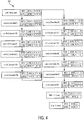
- FIG. 4 illustrates the BRDecompNet architecture 400 according to an embodiment of the present invention.
- conv1, conv2, conv3, and conv4 from BRNet are each decomposed into three light-weight convolutional layers that perform convolution for each dimension.
- conv1 in the BRNet architecture 300 of FIG. 3 is decomposed into conv1 a, conv1 b, and conv1 c in the BRDecompNet architecture 400 of FIG. 4 .
- Conv2 in the BRNet architecture 300 of FIG. 3 is decomposed into conv2a, conv2b, and conv2c in the BRDecompNet architecture 400 of FIG. 4 .
- Conv3 in the BRNet architecture 300 of FIG. 3 is decomposed into conv3a, conv3b, and conv3c in the BRDecompNet architecture 400 of FIG. 4 .
- Conv4 in the BRNet architecture 300 of FIG. 3 is decomposed into conv4a, conv4b, and conv4c in the BRDecompNet architecture 400 of FIG. 4 .
- Conv5 remains the same in the BRDecompNet architecture 500, resulting a total of 13 convolutional layers.
- Conv5 is followed by a flatten layer (“flatten_1”), which flattens the output of conv5 into a 1 D feature vector, and a dense layer (“dense_1”), which outputs a classification result the classifies a voxel as positive (bone) or negative (non-bone).
- flatten_1 flatten layer
- dense_1 dense layer
- the BRDecompNet deep CNN is trained using the training samples extracted from the training volumes in a similar manner to the BRNet network.
- Cross-entropy loss can be used during the training.
- Gradient descent and backpropagation can be used to find weights of the BRDecompNet layers that minimize the cross-entropy loss of the network over all of the training samples.
- the same training and testing dataset was used for the BRDecompNet as the BRNet.
- a final BRDecompNet version was trained based on a training set of 84 volumes, with 8,000 positive and negative samples respectively extracted from each training volume.
- BRDecompNet achieves approximately 80% reduction in computation time, as compared to BRNet.
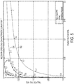
- FIG. 5 illustrates a receiver operating characteristic (ROC) comparison of the PBT, BRNet, BRDecompNet classifiers for bone segmentation.
- FIG. 5 shows the ROC curves for the PBT 502, BRNet 504, and BRDecompNet 506 for the 20 thorax abdomen volumes, with the corresponding probability threshold ranging from 0.1 to 0.9.
- applying the probability threshold of 0.5 on the PBT results in about 1% false positive rate and 81% true positive rate, while the same probability threshold on BRDecompNet results in about 1% false positive rate and 98% true positive rate.
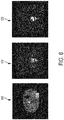
- FIG. 6 illustrates a comparison of probability maps generated using the PBT classifier and the BRDecompNet deep CNN classifier. As shown in FIG.
- image 600 is an original CTA image overlaid with an annotated mask 602 as ground truth
- image 610 is a probability map resulting from bone segmentation using a trained PBT classifier
- image 620 is a probability map resulting from bone segmentation using a trained BRDecompNet deep CNN classifier.
- the probability map 610 resulting from bone segmentation using the PBT includes many false positives in the renal artery and kidney, while the false positives are largely absent in the probability map 620 resulting from bone segmentation using the BRDecompNet.
- Bone segmentation and removal using BRDecompNet improves the classification accuracy as compared to the existing PBT-based method.
- Various embodiments of the present invention are described herein that make BRDecompNet reach similar performance as the existing PBT solution on a CPU, both in terms of runtime and memory consumption.
- Table 1 shows a comparison of runtime and memory consumption of the existing PBT-based bone removal and the BRDecompNet deep learning-based bone removal on 100+ unseen testing volumes.
- BRFGNet Filtered grouped version of BRNet
- FIG. 7 illustrates a network architecture 700 of BRFGNet according to an embodiment of the present invention.
- conv1, conv2, and conv3 in the BRNet architecture 300 of FIG. 3 are each divided into four groups and conv4 in the BRNet architecture 300 of FIG. 3 is divided into two groups.
- conv1 is divided into “conv1g1”, “conv1g2”, “conv1g3” and “conv1g4" in the BRFGNet architecture 700.
- Conv2 is divided into “conv2g1”, “conv2g2”, “conv2g3” and “conv2g4" in the BRFGNet architecture 700.
- Conv3 is divided into “conv3g1”, “conv3g2”, “conv3g3” and “conv3g4" in the BRFGNet architecture 700.
- Conv4 is divided into “conv4g1” and “conv4g2" in the BRFGNet architecture 700.
- merge_1 There are two merge operations (“merge_1” and “merge_2”) before conv4g1 and conv4g2 to merge the four output feature vectors into two.
- merge_3 Another merge operator before conv5 merges two output feature vectors into one.
- Multiple variances of filter-grouped networks can be trained including ones using decomposed features.
- the trained DNN is stored, for example on a memory or storage device of a computer system, and can then be used in the online bone removal stage 210 to segment bone structures in newly received CTA volumes.
- the online bone removal stage 210 includes steps 212-216.
- a CTA volume of a patient is received.
- the CTA volume can be a CTA volume of a specific region of the patient's body or can be whole body CTA volume acquired using a whole body scan of the patient.
- the CTA volume of the patient can be received directly from a CT scanner, or the CTA volume of the patient can be received by loading a CTA volume previously stored on a memory or storage of a computer system or receiving the CTA volume via a network transmission from another computer system.
- the present invention is not limited to a CTA volume and the method of FIG. 2 can be similarly applied to other types of medical images/volumes, as well.
- the method of FIG. 2 can be similarly performed on 3D or 2D medical image data of the patient acquired using various imaging modalities such as computed tomography (CT), combined positron emission tomography (PET)-CT, as magnetic resonance imaging (MRI), ultrasound, etc.
- CT computed tomography
- PET combined positron emission tomography
- MRI magnetic resonance imaging
- ultrasound etc.
- bone structures are segmented in the CTA volume using the trained deep neural network (DNN).
- the trained DNN can be a deep CNN trained for bone segmentation.
- the trained BRDecompNet deep CNN is used to segment the bone structures in the CTA volume.
- the BRNet deep CNN or the BRFGNet deep CNN can be used for the bone segmentation.
- the trained deep neural network e.g., BRDecompNet
- the trained DNN inputs a predetermined sized image patch surrounding the voxel and outputs a classification result (i.e., bone or non-bone) for the voxel.
- the size of the image patch corresponds to the size of the input layer in the trained DNN architecture.
- image patches of size 19 x 19 x 19 voxels can be input to the trained DNN, but the present invention is not limited thereto.
- a C++ implementation can be used to perform the segmentation by the trained DNN.
- Various embodiments provided herein for implementing the deep learning based bone segmentation by the trained DNN improve the speed and memory usage of the deep learning based segmentation.
- end-to-end convolution is performed. During the training of BRDecompNet , the training volumes are sampled in 19 x 19 x 19 image patches. However, if patch-wise convolution is used during the online bone removal stage, there are many unnecessary repetitive convolutions on proximate samples.
- the trained DNN can perform end-to-end convolution in which each layer of the trained DNN computes the feature maps for all of the voxels to be classifier and the trained DNN outputs a probability map or mask that provides the classification results for all of the voxels.
- convolution is performed on masked voxels.
- convolution only needs to be computed for voxels with intensities above 123 HU.
- intensity-based thresholding can be performed in the CTA volume prior to applying the trained DNN. This allows the trained DNN to only consider sufficiently bright voxels whose intensities are above an intensity threshold (e.g., 123 HU). This intensity thresholding results in a thresholded mask.
- a dilation of 19 x 19 x 19 kernel is performed on the thresholded mask.
- a speed gain of 40% is achieved by performing the convolution on the masked voxels.
- the memory allocation for the trained DNN can be made to be more contiguous.
- a 4D data tensor is used during the feed forward operation, with channel as the additional dimension.
- a 5D convolutional kernel is used, with the number of feature maps in the previous layer, as well as the number of feature maps in the next layer as additional two dimensions.
- the 4D data tensor is stored in order of CZYX, with kernel tensor stored in NCZYX, where N and C is the number of feature maps in the next and previous layer, respectively. During the convolution, this order might bring slowdown, since the memory access is not contiguous in the channel. For simplicity sake, FIG.
- the order of CX is used for the data tensor
- NCX is used for the kernel tensor. It can be seen in FIG. 8 that, in order to perform one convolution operation, the memory needs to jump every N x slot to access the same image index location (0, 1, 2, 3, ...) in the next feature map (FeatureMap 0, FeatureMap 1, FeatureMap 2) where N x is the dimension of the feature map size.
- the compiler favors contiguous memory access.
- the NCZYX order can be changed to NZYXC, where the feature values of all the channels corresponding to the same feature map are indexed together.
- the present inventors have observed up to a 25% speed improvement by changing the NCZYX order to NZYXC, where the feature values of all the channels corresponding to the same feature map are indexed together.
- 2D slices can be allocated to columns of an image matrix used for the convolution instead of 3D images.
- the convolution involves matrix multiplication M I ⁇ M k .
- M I is referred to herein as the "image matrix", which is a N s ⁇ N c N x N y N z matrix, where N s is the number of columns (samples), N c is the number of channels in the previous layer, and N z , N y , and N x are the kernel dimension in Z, Y and X, respectively.
- N s is typically all the samples in the image. This is not a problem for a 2D image.
- BRDecompNet assuming that convolution is performed on a 200 x 160 x 160 volume and 6% voxels are above 123 HU, the number of voxels after 19 x 19 x 19 dilation that need to go through convolution is 30%.
- M I is allocated slice-by-slice, which greatly reduces N s . Accordingly, this embodiment provides special handling for 3D volumetric medical image data in order to reduce the memory consumption required for the convolution of the 3D volumetric medical image data.
- a library such as Integrated Performance Primitives (IPP) and Math Kernel Library (MKL) can be used.
- Libraries such as IPP and MKL, provide optimized functions for matrix multiplication with low-level vectorization and Single Instruction Multiple Data (SIMD) instructions.
- SIMD Single Instruction Multiple Data
- bone removal in the CTA volume is performed and non-bone structures in the CTA volume are visualized.
- a 3D visualization of the CTA volume is generated using VRT.
- the segmented bone structures are removed from the 3D visualization of the CTA volume.
- the bone structures can be removed from the 3D visualization of the CTA volume by setting the intensity of voxels classified as bone voxels in the CTA image to zero.
- the 3D visualization of the CTA image provides a 3D visualization of the non-bone structures (e.g., vascular structures) in the CTA image.
- the 3D visualization of the non-bone structures in the CTA image can be displayed, for example on a display device of a computer system.
- Image 130 of FIG. 1 shows a 3D VRT visualization of non-bone structures resulting from performing deep learning-based bone removal on the CTA volume 100 using the BRDecompNet deep CNN according to an embodiment of the present invention
- the trained DNN is a deep CNN (e.g., BRNet, BRDecompNet).
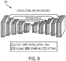
- the DNN for bone segmentation can be trained by end-to-end training of a deep convolutional encoder-decoder (CED).
- FIG. 9 illustrates an exemplary architecture 900 of a deep CED.
- the downsampling and upsampling layers in the deep CED 900 an significantly increase the receptive field, thus more contextual information can be used; and (2) The deep CED 900 is trained in an image-to-image way, such that there is no need to do random sampling on a subset of samples.
- a deep image-to-image network (DI2IN) trained using multi-task learning (MTL) can be used to perform bone segmentation and bone removal in a CTA volume.
- the trained DI2IN (described in greater detail below) can be used as the trained DNN in the method of FIG. 2 .
- a bone mask generated by the trained DI2IN can be used by itself to perform the bone removal in step 216 of FIG. 12 .
- the bone mask generated by the trained DI2IN can be used together an aorta mask and a vessel mask to generate a final mask for bone removal using the method shown in FIG. 10 .
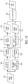
- FIG. 10 illustrates a method for bone removal in a CTA volume using a DI2IN and MTL according to an embodiment of the present invention.
- an input image 1002 is received.
- the input image 1002 is a CTA volume.
- the input CTA volume 1002 may be received directly from an image acquisition device (i.e., a CT scanner) or may be received by loading a previously acquired CTA volume.
- an image acquisition device i.e., a CT scanner
- ⁇ In the color mapping of 3D volume rendering, only voxels with intensities higher than a certain intensity threshold ⁇ are displayed. For a given CTA volume V, the method of FIG.
- DI2IN trained using MTL is used to perform bone segmentation 1004 and landmark detection 1006 in the input image 1002.
- DI2IN, MTL, bone segmentation 1004 and landmark detection 1006 are described in greater detail below.
- the bone segmentation 1004 results in a bone mask 1008.
- the landmark detection 1006 results in landmark locations 1010.
- the bone mask 1008 and landmark locations 1010 are used to perform region-growing based aorta segmentation 1012 and vessel tracing 1014.
- the region-growing based aorta segmentation 1012 results in an aorta mask 1016 and the region-growing based vessel tracing 1014 results in a vessel mask 1018.
- a connected component (CC) analysis 1020 is then performed based on the bone mask 1008, the aorta mask 1016 and the vessel mask 1018 to generate a final mask 1022 used for bone removal in the input image.
- Methods for performing the region-growing based segmentation/vessel growing and the CC analysis for generating the final mask are described in greater detail in United States Publication No. 2016/0328855, filed May 4, 2015 and entitled "Method and System for Whole Body Bone Removal and Vascular Visualization in Medical Image Data", the disclosure of which is incorporated herein in its entirety by reference.
- a 3D convolution kernel has the advantages of utilizing more contextual information, comparing to a 2D counterpart.
- a 3D DI2IN would have to be trained from scratch, since no pre-trained network that sees millions of examples is available. Insufficient training data may result in poor generalization for such a 3D DI2IN.
- one unified network (DI2IN) is used to learn both bone segmentation and body landmark detection, where the later is an auxiliary task, with the goal to improve generalization of learning of the primary task of bone segmentation.
- Reasons for applying such transfer learning / MTL strategy include: (1) Both tasks can be formulated by DI2IN in the same resolution (e.g. 2 mm), where common features are shared; (2) The number of volumes with annotated landmark is much larger than volumes with annotated bone. This enables the MTL network to see more training images; and (3) The bone shape has very high correlation with body region.
- Equation (1) shows the general MTL framework that the present inventors have adapted to the application of bone segmentation.
- N t training data x i t and label y i t there are N t training data x i t and label y i t , while i ⁇ ⁇ 1, ..., N t ⁇ .
- f x i t w t is a function of x i t and parameterized by a weight vector w t .
- the summation takes the loss function and weight regularization term ⁇ t ( w t ) .
- ⁇ t is the importance coefficient of task t 's cost. It can be noted that in the present application, both the data and the loss function can be different among the tasks.
- DI2IN trains a deep neural network that performs a mapping of an input image to an output image.
- a medical image volume such as a CTA volume is input to the DI2IN and the DI2IN outputs an image in which for each voxel a probability value is given to represent the likelihood of being bone or not.
- the probability value from v ⁇ V h is set to zero after the DI2IN feed forward operation.
- M ( v ) can be also reformatted into a weighting function to balance the biased distribution of bone and vessel in some body regions.
- the auxiliary task aims to detect eight body landmarks: including carina bifurcation, left and right kidney center, left and right hip bone, brachiocephalic artery bifurcation, left common carotid artery and left subclavian artery. Those landmarks are present in different regions of the body. Those landmarks are first used to generate heat maps with Gaussian blobs that are centered at their locations in the training images. The width of the Gaussian function is empirically determined. To cope with the sparsity of the positive landmark heat value in the map, mean square error metric is used as the loss function in equation (4), where y i r is the ground truth heat map.
- FIGS. 11A and 11B illustrate exemplary network architectures for a 2D DI2IN and a 3D MTL DI2IN, respectively.
- the 3D MTL DI2IN architecture 1110 is branched into two parts for each task (bone segmentation and landmark detection), where w b and w r in equation (2) share common weights. In both transfer and multi-task learning, only those weights are shared or transferred across tasks.
- the two branched decoding paths corresponding to the two tasks only differ in the last non-linear layer output.
- the cross entropy loss of the bone segmentation and mean square loss of the landmark heatmap is handled by Sigmoid and ReLu layers, respectively.
- FIG. 11A shows the DI2IN architecture 1100 used for 2D bone segmentation.
- the 2D DI2IN architecture 1100 has similar architecture with deep CED, and can be loaded with pre-trained VGG weights.
- the 2D network 1100 has 16 M parameters, corresponding to about 64 MB disk size.
- the 3D MTL network 1110 has 293 K parameters and corresponds to 1.15 MB disk size.
- a total of 1090 3D CTA volumes with bone annotation which cover a variety of different body regions, kV range, fields of view, reconstruction kernels, slice thickness, patient age and pathologies, were used for training the MTL DI2IN. All those 3D CTA volumes have 2D axial slice dimension of 512 x 512, with a resolution ranging from 0.4 mm to 0.7 mm. The slice thickness ranges from 0.4 mm to 5 mm. Among those data, 123 volumes are fully annotated in resampled 2 mm resolution, while the remaining 967 volumes are annotated in sparse 2D slices at an original resolution.
- the landmark heat map regression is based on a set of 2467 3D CT volumes, which are all resampled to 2 mm. Both of the bone and landmark annotations were made by 10 medical students and were at least reviewed and corrected for two times.
- the data is randomly shuffled and split into 75% for training and 25% for testing.
- the training was performed using a NVIDIA TitanX GPU with 12 GB memory.
- the fed 3D volumes are automatically cropped to multiple sub-volumes when the size is larger than a certain threshold.
- the training was based on the Theano framework with CUDA 7.5 and cuDNN 5.0 support.
- Table 2 shows the area under the curve (AUC) of the ROC curve of different DI2IN experiment settings, including learning rate ⁇ , regularization weight ⁇ , and 2D/3D configuration.
- MTL-1 and MTL-2 represent results of bone segmentation in testing data using MTL-based 3D DI2IN with different DI2IN experiment settings.
- STL-1, STL-2, STL-3, and STL-4 represent results of bone segmentation using single task learning(STL)-based 3D DI2IN with different DI2IN experiment settings.
- 2D-t represents results of bone segmentation using a 2D DI2IN trained using transfer learning from VGG-net
- 2D-s represents results of bone segmentation using a 2D DI2IN trained from scratch.
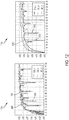
- FIG. 12 illustrates a comparison of 3D DI2IN learning curves for testing data using different DI2IN experimental settings.
- image 1200 shows 3D DI2IN learning curves for STL-1 1202, STL-2 1204, and MTL-1 1206, which used a learning rate of 1 e -3 .
- Image 1210 shows 3D DI2IN learning curves for STL-3 1212, STL-4 1214, and MTL-2 1216, which used a learning rate of 1 e -4 .
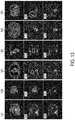
- FIG. 13 illustrates a comparison of probability maps of axial CTA slices resulting from bone segmentation using an STL-based DI2IN and an MTL-based DI2IN.
- images 1300, 1310, 1320, 1330, 1340, and 1350 show original axial CTA slices.
- Images 1302, 1312, 1322, 1332, 1342, and 1352 show probability maps resulting from bone segmentation using STL-1 in images 1300, 1310, 1320, 1330, 1340, and 1350, respectively.
- Images 1304, 1314, 1324, 1334, 1344, and 1354 show probability maps resulting from bone segmentation using MTL-1 in images 1300, 1310, 1320, 1330, 1340, and 1350, respectively.
- the probability maps whiter voxels correspond to higher probability of bones from the final Sigmoid output. Erroneous bone detection areas are circled in the probability maps 1302, 1312, 1322, 1332, 1342, and 1352 generated using STL-1. It is worth mentioning that the first column (images 1300, 1302, and 1304) is a very abnormal case with an aneurysm. Such an aneurysm does not exist in the training data set for STL. With MTL, the network is able to do a better job after seeing 24 times more training images.
- the present inventors compared the proposed DI2IN framework with two existing approaches (watershed-SVM and PBT) on 329 unseen volumes.
- Two medical students subjectively evaluated the quality with severity scores in categories like "vessel cuts" and "bone fragments remaining". The score ranges from 0 to 3, where 0 means no issue at all and 3 means very obvious defect.
- Table 3 shows the histogram of the severity scores with body region details. It can be seen that watershed does a good job in keeping organs intact (e.g. kidneys), but the number of failure cases in bone remaining and vessel cut is large. PBT is slightly better in these two items, with worse performance in the other.
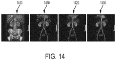
- FIG. 14 illustrates exemplary results 3D visualizations of non-bone structures resulting from performing bone removal in a CTA volume.
- image 1400 shows a 3D VRT visualization of the original CTA volume
- image 1410 shows a 3D VRT visualization of the bone removal result using the PBT-based approach
- image 1420 shows a 3D VRT visualization of the bone removal result using the SVM+watershed based approach
- image 1430 shows a 3D VRA visualization of the bone removal result using MTL DI2IN bone segmentation according to an embodiment of the present invention.
- bone removal is performed jointly with vessel regression.
- This embodiment addresses the vessel-cut problem caused by bone segmentation (bone removal) algorithms.
- one problem that may greatly influence bone-removal result is the appearance of a vessel-cut.
- Previous methods use post-processing techniques such as vessel tracing to fill those cuts.
- One possible drawback of using such post-processing methods is that the whole pipeline is not jointly optimized.
- This embodiment of the present invention provides a unified optimization framework to jointly regress vessels (trace vessels) and remove bone structures.
- FIG. 15 illustrates a method for joint bone removal and vessel regression in a CTA volume according to an embodiment of the present invention.
- input volume 1502 is received.
- the input image 1502 is a CTA volume.
- the input CTA volume 1502 may be received directly from an image acquisition device (i.e., a CT scanner) or may be received by loading a previously acquired CTA volume.
- image acquisition device i.e., a CT scanner
- 3D volume rendering using VRT only voxels with intensities higher than a certain intensity threshold (e.g., 132 HU) are displayed. Accordingly, masking / intensity thresholding can be applied to remove voxels with intensities less than the intensity threshold prior to performing the bone segmentation and vessel regression.
- intensity threshold e.g., 132 HU
- a trained deep pyramid bone segmentation network 1504 performs bone segmentation in the input volume 1502 and a trained deep pyramid vessel regression network 1506 performs vessel regression (i.e., vessel tracing) in the input volume 1502.
- respective DNNs are trained for bone segmentation and for vessel regression, the respective networks for both bone and vessel segmentation are each trained using a Deep Image-to-Image Network (DI2IN) with a structural adjustment - Pyramid Scene Parsing (PSP) on the decoder part of the DI2IN. Additional details regarding the DI2IN are described in U.S. Patent No.
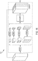
- FIG. 16 illustrates an exemplary structure of a PSP Module 1600.
- the PSP module 1600 inputs a feature map, performs a pyramid of pooling operations to capture contexts of the input feature map in a coarse-fine-manner, convolves the pooled features, and then upsamples and concatenates the features.
- a PSP module is added on the decoder part of the DI2IN architecture.
- a PSP module ca can be added at the last convolutional layer of the DI2IN architecture.
- a pyramid of the pooling operations is used to capture feature contexts in a coarse-to-fine manner. These features are convolved, upsampled to the original image size, and concatenated. Using such an ensemble of long- and short-range feature sets, the DI2IN-PSP network yields more accurate segmentation results for both bone segmentation and vessel segmentation.
- the trained deep pyramid bone segmentation network 1504 segments bone structures in the input volume 1502, resulting in a bone mask 1508, and the trained deep pyramid vessel regression network 1506 traces vessels in the input volume 1502, resulting in a vessel mask 1510.
- the bone mask 1508 and the vessel mask 1510 are the integrated to generate a final mask 1512 that is used to perform bone removal in the input volume 1502.
- a connected component analysis can performed based on the bone mask 1508 and the vessel mask 1510 to generate a final mask 1022 used for bone removal in the input image.
- a method for performing such a connected component analysis for generating the final mask is described in greater detail in United States Publication No. 2016/0328855, filed May 4, 2015 and entitled "Method and System for Whole Body Bone Removal and Vascular Visualization in Medical Image Data", the disclosure of which is incorporated herein in its entirety by reference.
- the present inventors comparing the bone removal results on two datasets using the existing watershed+SVM based approach and joint bone removal and vessel regression using trained DI2IN-PSP networks.
- the experiments were performed on isotopically resampled datasets.
- the methods were tested on 30 head and neck CTA volumes at 1 mm resolution.
- Table 4 illustrates the accuracy, sensitivity, and specificity of the bone removal results in the head and neck dataset using the previous technique (“Before”) and using joint bone removal and vessel regression using trained DI2IN-PSP networks ("After”). The methods were also tested on 25 whole body CTA volumes at 2 mm resolution.
- Table 5 illustrates the accuracy, sensitivity, and specificity of the bone removal results in the whole body dataset using the previous technique (“Before”) and using joint bone removal and vessel regression using trained DI2IN-PSP networks (“After”).
- Table 4 Accuracy Sensitivity Specificity Before 0.957 0.984 0.834 After 0.978 0.988 0.921
- Table 5 Accuracy Sensitivity Specificity Before 0.948 0.950 0.974 After 0.992 0.994 0.979
- Computer 1702 contains a processor 1704, which controls the overall operation of the computer 1702 by executing computer program instructions which define such operation.
- the computer program instructions may be stored in a storage device 1712 (e.g., magnetic disk) and loaded into memory 1710 when execution of the computer program instructions is desired.
- a storage device 1712 e.g., magnetic disk
- FIGS. 2 , 10 , and 15 may be defined by the computer program instructions stored in the memory 1710 and/or storage 1712 and controlled by the processor 1704 executing the computer program instructions.
- An image acquisition device 1720 such as an MR scanning device or a CT scanning device, can be connected to the computer 1702 to input image data to the computer 1702. It is possible to implement the image acquisition device 1720 and the computer 1702 as one device. It is also possible that the image acquisition device 1720 and the computer 1702 communicate wirelessly through a network. In a possible embodiment, the computer 1702 can be located remotely with respect to the image acquisition device 1720 and the method steps described herein can be performed as part of a server or cloud based service. In this case, the method steps may be performed on a single computer or distributed between multiple networked computers. The computer 1702 also includes one or more network interfaces 1706 for communicating with other devices via a network.
- the computer 1702 also includes other input/output devices 1708 that enable user interaction with the computer 1702 (e.g., display, keyboard, mouse, speakers, buttons, etc.). Such input/output devices 1708 may be used in conjunction with a set of computer programs as an annotation tool to annotate volumes received from the image acquisition device 1720.
- input/output devices 1708 may be used in conjunction with a set of computer programs as an annotation tool to annotate volumes received from the image acquisition device 1720.
- FIG. 17 is a high level representation of some of the components of such a computer for illustrative purposes.
Landscapes
- Engineering & Computer Science (AREA)
- Health & Medical Sciences (AREA)
- Life Sciences & Earth Sciences (AREA)
- Medical Informatics (AREA)
- Physics & Mathematics (AREA)
- Biomedical Technology (AREA)
- Biophysics (AREA)
- General Health & Medical Sciences (AREA)
- Molecular Biology (AREA)
- Public Health (AREA)
- Pathology (AREA)
- Radiology & Medical Imaging (AREA)
- Optics & Photonics (AREA)
- Heart & Thoracic Surgery (AREA)
- Nuclear Medicine, Radiotherapy & Molecular Imaging (AREA)
- Surgery (AREA)
- Animal Behavior & Ethology (AREA)
- High Energy & Nuclear Physics (AREA)
- Veterinary Medicine (AREA)
- Computer Vision & Pattern Recognition (AREA)
- Theoretical Computer Science (AREA)
- General Physics & Mathematics (AREA)
- Vascular Medicine (AREA)
- Dentistry (AREA)
- Oral & Maxillofacial Surgery (AREA)
- Computing Systems (AREA)
- Computational Linguistics (AREA)
- Data Mining & Analysis (AREA)
- Evolutionary Computation (AREA)
- Artificial Intelligence (AREA)
- General Engineering & Computer Science (AREA)
- Mathematical Physics (AREA)
- Software Systems (AREA)
- Pulmonology (AREA)
- Image Analysis (AREA)
- Apparatus For Radiation Diagnosis (AREA)
Abstract
Description
- This application claims the benefit of
U.S. Provisional Application No. 62/415,075, filed October 31, 2016 - The present invention relates to bone segmentation and removal in medical image data, and more particularly, to automated removal of bone voxels from 3D computed tomography angiography images in order to visualize vessels in the 3D computed tomography angiography images.
- Bone segmentation and removal in computed tomography angiography (CTA) is an important clinical application. CTA is a medical imaging technique that is often used to visualize the blood vessels in a patient's body. Computed tomography (CT) combines a series of X-ray images taken from different angles and uses computer processing to create cross-sectional images, or slices, of bones, blood vessels and soft tissues inside the body. The cross-sectional images, or slices, can be combined to generate 3D CT volumes. In CTA, a contrast agent is injected into the bloodstream of the patient prior to CT imaging in order to generate contrast enhanced CT images that visualize the patient's vessels. CTA volumes can be visualized using a volume rendering technique (VRT) so that clinicians are able to see 3D vascular structures and pathologies such as stenoses and aneurysms. The goal of bone removal is to segment and remove bone voxels from CTA volumes to yield a vascular-only view, which provides an unhindered 3D view of the vascular structures in the CTA volume.
- In CTA images, there is an overlapping intensity between the distributions of bones and contrast enhanced vessels. That is bone and contrast enhance vessels appear with similar intensity in CTA images. Accordingly, bones can be a major obstacle in the visualization and analysis of vessel trees, aneurisms, and calcifications using CTA, and it is desirable to remove bone structures from CTA images in order to achieve a better visualization of the vessels. In the past, manual editing techniques have been used to extract and remove bone structures from the image data. However, the tedious and long operating time required for manual editing is prohibitive for it to be of practical use. Furthermore, due to image resolution and noise in the image data, bones and vessels with overlapping intensity distributions often appear to be connected, which creates significant challenges in automated segmentation and removal of bone structures from the image data.
- Automatic bone removal in CTA volumes is a challenging task, due to the fact that many osseous and vascular structures have similar patterns in shape and contrast. Previous approaches generally can be categorized into top-down and bottom-up approaches. Top-down approaches include statistical shape model and image atlas based approaches. These approaches typically need strong initial information about the body region or landmark location, which make them difficult to apply in various field of views (FOV). In the bottom-up category, many approaches are designed for non-contrasted scans, including region-growing and super-voxel approaches. However, in CTA volumes, the existence of contrast agent enhances vessel intensities and significantly increases the complexity of the problem, and such approaches have difficulty is differentiating bone and non-bone regions in some regions in CTA volumes (e.g., subclavian) due to weak gradient and highly similar appearance of the bone and non-bone regions.
- The present invention provides a method and system (apparatus) for deep learning based bone removal in computed tomography angiography (CTA) images.
- In an embodiment of the present invention, bone structures are segmented in a 3D medical image of a patient by classifying voxels of the 3D medical image as bone or non-bone voxels using a deep neural network trained for bone segmentation. A 3D visualization of non-bone structures in the 3D medical image is generated by removing voxels classified as bone voxels from a 3D visualization of the 3D medical image.
Advantageously, the 3D medical image of the patient is a computed tomography angiography (CTA) volume.
Further, generating a 3D visualization of non-bone structures in the 3D medical image by removing voxels classified as bone voxels from a 3D visualization of the 3D medical image can comprise: - setting an intensity value to zero for each the voxels classified as a bone voxels in the 3D visualization of the 3D medical image.
- using end-to-end convolution over all of a plurality of voxels being classified in the 3D medical image to perform convolutions required in convolutional layers of the decomposed version of the deep CNN.
- performing intensity-based thresholding to generate an initial mask of voxels in the 3D medical image having intensities greater than an intensity threshold;
- performing dilation on the initial mask of voxels using a kernel having a size corresponding to an receptive field of the decomposed version of the deep CNN; and
- classifying the voxels in the initial mask as bone or non-bone voxels based by performing convolutions on the dilated initial mask using the decomposed version of the deep CNN.
- allocating 2D slices of image patches in the 3D medical image to columns of an image matrix that is multiplied by a kernel matrix to perform convolutions required in convolutional layers of the decomposed version of the deep CNN.
- controlling memory allocated to store feature values of layers of the DNN such that feature values of all channels corresponding to a same feature map index are grouped together.
- segmenting the bone structures in the 3D medical image of the patient using a deep image-to-image network (DI2IN) trained using multi-task learning to segment the bone structures by generating a bone mask of the 3D medical image and to detect anatomical landmarks in the 3D medical image by generating a landmark heatmap of the 3D medical image.
- jointly segmenting bone structures using a trained deep pyramid bone segmentation network and tracing vessel structures in the 3D medical image using a trained deep pyramid vessel regression network, wherein each of the trained deep pyramid bone segmentation network and the trained deep pyramid vessel regression network is a deep image-to-image network (DI2IN) with a pyramid scene parsing model added at a last convolutional layer of the DI2IN; and
- generating a final bone mask of the 3D medical image based on an initial bone mask generated by the trained deep pyramid bone segmentation network and a vessel mask generated by the trained deep pyramid vessel regression network.
- means for segmenting bone structures in a 3D medical image of a patient by classifying voxels of the 3D medical image as bone or non-bone voxels using a deep neural network trained for bone segmentation; and
- means for generating a 3D visualization of non-bone structures in the 3D medical image by removing voxels classified as bone voxels from a 3D visualization of the 3D medical image.
- means for performing intensity-based thresholding to generate an initial mask of voxels in the 3D medical image having intensities greater than an intensity threshold;
- means for performing dilation on the initial mask of voxels using a kernel having a size corresponding to an receptive field of the decomposed version of the deep CNN; and
- means for classifying the voxels in the initial mask as bone or non-bone voxels based by performing convolutions on the dilated initial mask using the decomposed version of the deep CNN.
- means for segmenting the bone structures in the 3D medical image of the patient using a deep image-to-image network (DI2IN) trained using multi-task learning to segment the bone structures by generating a bone mask of the 3D medical image and to detect anatomical landmarks in the 3D medical image by generating a landmark heatmap of the 3D medical image.
- means for jointly segmenting bone structures using a trained deep pyramid bone segmentation network and tracing vessel structures in the 3D medical image using a trained deep pyramid vessel regression network, wherein each of the trained deep pyramid bone segmentation network and the trained deep pyramid vessel regression network is a deep image-to-image network (DI2IN) with a pyramid scene parsing model added at a last convolutional layer of the DI2IN; and
- means for generating a final bone mask of the 3D medical image based on an initial bone mask generated by the trained deep pyramid bone segmentation network and a vessel mask generated by the trained deep pyramid vessel regression network.
- These and other advantages of the invention will be apparent to those of ordinary skill in the art by reference to the following detailed description and the accompanying drawings.
-
-
FIG. 1 illustrates exemplary bone segmentation results of a computed tomography angiography (CTA) volume using various techniques; -
FIG. 2 illustrates a method for deep learning based bone removal in CTA images according to an embodiment of the present invention; -
FIG. 3 illustrates a BRNet network architecture according to an embodiment of the present invention; -
FIG. 4 illustrates a BRDecompNet architecture according to an embodiment of the present invention; -
FIG. 5 illustrates a receiver operating characteristic (ROC) comparison of PBT, BRNet, BRDecompNet classifiers for bone segmentation; -
FIG. 6 illustrates a comparison of probability maps generated using a PBT classifier and a BRDecompNet deep CNN classifier; -
FIG. 7 illustrates a BRFGNet network architecture according to an embodiment of the present invention; -
FIG. 8 illustrates an example of memory allocation for convolution on 1D data; -
FIG. 9 illustrates an exemplary architecture of a deep convolutional encoder-decoder (CED); -
FIG. 10 illustrates a method for bone removal in a CTA volume using a deep image-to-image network (DI2IN) and multi-task learning (MTL) according to an embodiment of the present invention; -
FIGS. 11A and 11B illustrate exemplary network architectures for a 2D DI2IN and a 3D MTL DI2IN, respectively; -
FIG. 12 illustrates a comparison of 3D DI2IN learning curves for testing data using different DI2IN experimental settings; -
FIG. 13 illustrates a comparison of probability maps of axial CTA slices resulting from bone segmentation using an single task learning based DI2IN and an MTL-based DI2IN; -
FIG. 14 illustrates exemplary results 3D visualizations of non-bone structures resulting from performing bone removal in a CTA volume; -
FIG. 15 illustrates a method for joint bone removal and vessel regression in a CTA volume according to an embodiment of the present invention; -
FIG. 16 illustrates an exemplary structure of a pyramid scene parsing (PSP) module; and -
FIG. 17 is a high-level block diagram of a computer capable of implementing the present invention. - The present invention relates to a method and system for deep learning based bone removal in computed tomography angiography (CTA) images. Embodiments of the present invention are described herein to give a visual understanding of the deep learning based bone removal method. A digital image is often composed of digital representations of one or more objects (or shapes). The digital representation of an object is often described herein in terms of identifying and manipulating the objects. Such manipulations are virtual manipulations accomplished in the memory or other circuitry / hardware of a computer system. Accordingly, is to be understood that embodiments of the present invention may be performed within a computer system using data stored within the computer system.
- Automatic removal on bones in CTA images is a challenging task, due to the fact that many osseous and vascular structures have similar patterns of shape and contrast. The close proximity of bones and vessels, such as the vessels close to the skull base or the part of the aorta close to the spine, further complicates automated bone segmentation and removal. One existing technique for bone removal in CTA applies a hierarchical watershed transform as a preparation stage for both a support vector machine (SVM)-based automatic approach and an interactive editing step. Although the automatic processing time of the watershed implementation is fast (on average 20 seconds for a test dataset of 100 volumes), the quality is not satisfactory for a significant number of cases.
FIG. 1 illustrates exemplary bone segmentation results of a CTA volume using various techniques. As illustrated inFIG. 1 ,image 100 shows a 3D visualization of an original CTA volume visualized using volume rendered technique (VRT).Image 110 shows a result of performing bone removal on theCTA volume 100 using the SVM-based watershed algorithm. As shown inimage 110, a number of rib bones were not successfully removed by the SVM-based watershed algorithm. Another existing technique for automated bone removal in CTA feeds combined random shift intensity difference (RSID) features and landmark features into a probabilistic boosting tree (PBT) classifier. Although the PBT-based algorithm reaches an overall superior quality level with respect to the SVM-based watershed algorithm, the PBT-based algorithm is still problematic in some scenarios, such as in the thorax abdomen region.Image 120 ofFIG. 1 shows a result of performing bone removal on theCTA volume 100 using the PBT-based algorithm. As shown inimage 120, a kidney is missing and a rib was not removed using the PBT-based algorithm. - Embodiments of the present invention provide a dep learning based method for bone classification/segmentation and removal in CTA images. The deep learning based bone removal described herein achieves improved recognition quality as compared with the existing computer-based bone removal techniques described above.
Image 130 ofFIG. 1 shows a result of performing deep learning-based bone removal on theCTA volume 100 according to an embodiment of the present invention. As shown inimage 130, the results of bone removal using the deep learning based method of the present invention is significantly improved as compared to theresults -
FIG. 2 illustrates a method for deep learning based bone removal in CTA images according to an embodiment of the present invention. The method ofFIG. 2 includes atraining stage 200 and an onlinebone removal stage 210. Thetraining stage 200, which includes steps 202-206, is performed off-line to train a deep neural network (DNN) for bone segmentation/classification. The onlinebone removal stage 210, which includes steps 212-216, performs bone removal on a newly received CTA volume using the trained DNN resulting from thetraining stage 200. Once the DNN for bone segmentation/classification is trained in thetraining stage 200, the onlinebone removal stage 210 can be repeated for each newly received CTA image to perform bone removal on each newly received input CTA image using the trained DNN. - At
step 202, training volumes are received. The training volumes can be 3D medical image volumes with annotated bone structures. In an advantageous implementation, the training volumes are CTA volumes with annotated bones structures. For example, the bone structures can be annotated manually by an expert. The training volumes can be received by loading stored training volumes from a database. - At
step 204, training samples are extracted from each of the training volumes. Intensity thresholding is applied to each training volume to find voxels having intensities above a certain intensity threshold. For example, an intensity threshold of 123 Hounsfield units (HU), which is an intensity given by a transfer function of volume rendering technique (VRT). Positive (bone) and negative (non-bone) voxels that are above the intensity threshold are randomly sampled for each training volume. In an exemplary implementation, 2000 positive and negative voxels above the intensity threshold are randomly sampled from each training volume, but the present invention is not limited thereto. A training sample is generated for each of the sampled positive and negative voxels by extracting an image patch surrounding the voxel. In an advantageous implementation, a 19 x 19 x 19 image patch is extracted for each training sample. - At
step 206, a deep neural network (DNN) for bone segmentation is trained based on the training samples. The DNN is trained to segment bone structures in a medical image (e.g., a CTA image) by classifying voxels in the medical image as positive (bone) or negative (non-bone). According to an advantageous embodiment, a deep convolutional neural network (CNN) can be trained for bone segmentation based on the training samples. - In recent years deep CNNs have enjoyed great success in image classification and other computer vision tasks. However, a major concern with applying CNNs lies in the expensive computations involved. With modern graphic processing units (GPU), CNNs have become a commodity in dealing with 2D RGB or gray-scale images in the computer vision field. However, in the medical imaging domain, especially for central processing unit (CPU)-based environments, an efficient implementation of 3D convolution is needed. Embodiments of the present invention described herein provide a deep CNN that reaches similar performance as the existing PBT-based solution in both runtime and memory consumption, while providing superior classification accuracy. In an advantageous embodiment of the present invention, a decomposed convolutional neural network, referred to herein as "BRDecompNet", is trained and used to perform bone segmentation. BRDecompNet reaches similar performance as the existing PBT-based solution in both runtime and memory consumption, while providing superior classification accuracy. A deep convolutional network, referred to herein as "BRNet" is described first followed by BRDecompNet, which is a decomposed version of BRNet.
- Convolutional networks typically involve stacking of multiple layers of convolution and non-linear mapping, and possibly down-sampling and deconvolution. The representative capacity is controlled by the depth and breadth of the network. Although a deeper and broader network is able to have more representative power, such a network requires a computationally expensive feed forward operation. According to an advantageous embodiment of the present invention, the present inventors have developed the BRNet network architecture to achieve a balance between complexity and efficiency.
-
FIG. 3 illustrates theBRNet network architecture 300 according to an embodiment of the present invention. As shown inFIG. 3 ,BRNet 300 includes an input layer ("input_1") that inputs a 19 x 19 x 19 image patch of a CTA image.BRNet 300 further includes five convolutional layers ("conv1", "conv2", "conv3", "conv4", and "conv5"). Each of conv1, conv2, conv4, and conv5 includes eight feature maps, each applying a 5 x 5 x 5 filter on the image. Conv3 is the heaviest layer, which uses 16 feature maps with a 7 x 7 x 7 filter. Each convolutional layer is followed by a rectified linear unit (ReLu) nonlinear filter. A softmax layer is used after conv5. There is no down-sampling or up-sampling in theBRNet network 300 ofFIG. 3 . - The BRNet deep CNN is trained using the training samples extracted from the training volumes. Cross-entropy loss can be used during the training. Gradient descent and backpropagation can be used to find weights of the BRNet layers that minimize the cross-entropy loss of the network over all of the training samples. In an exemplary implementation by the present inventors, 48 training volumes were used to train the BRNet deep CNN. 2000 positive and negative voxels above the intensity threshold of 123 HU were sampled from each training volume and an image patch of 19 x 19 x 19, which is the input size of the
network 300 ofFIG. 3 , was extracted for each training sample. BRNet results in improved accuracy, as compared to the existing PBT-based method, as shown inFIG. 5 , which is discussed below. However, in the tests performed by the present inventors, BRNet required a longer runtime as compared with the existing PBT-based method and the existing SVM-based watershed method. - In an advantageous embodiment, a decomposed version of BRNet, referred to herein as "BRDecompNet" can be trained for bone segmentation. 3D convolution is very slow. According to an advantageous embodiment, convolutional layers in BRNet can be decomposed into three light-weighted convolutional layers that respectively perform the convolution for each dimension. For example, conv3 of BRNet requires 16 convolutions with 8 x 7 x 7 x 7 4D kernel. In the BRDecompNet architecture, this heavy convolution is replaced with three light-light weights convolutional layers, which are composed of 16 x 8 x 7 x 1 x 1, 16 x 16 x 1 x 7 x 1, and 16 x 16 x 1 x 7, respectively. This reduces the number of weights, as well as the number of multiplication operations needed from 43904 to 4480 (bias is not counted for simplicity). Without loss of generality, let Np denote the number of feature maps in the previous layer. Nc denotes the number of feature maps in the current layer. The kernel size of the original network is assumed to be Nx, Ny, Nz. Such a convolutional layer requires NcNpNxNyNz weights as well as multiplication operations. For the decomposed module, if Np is applied to each of the decomposed layers, the number of weights is (NcNpNx + NpNpNy + NpNpNz ), which typically results in one magnitude of order less weights and multiplication operations. Following, this methodology for decomposing convolution layers, BRNet is decomposed into BRDecompNet.
-
FIG. 4 illustrates theBRDecompNet architecture 400 according to an embodiment of the present invention. As shown in theBRDecompNet architecture 400 ofFIG. 4 , conv1, conv2, conv3, and conv4 from BRNet are each decomposed into three light-weight convolutional layers that perform convolution for each dimension. In particular, conv1 in theBRNet architecture 300 ofFIG. 3 is decomposed into conv1 a, conv1 b, and conv1 c in theBRDecompNet architecture 400 ofFIG. 4 . Conv2 in theBRNet architecture 300 ofFIG. 3 is decomposed into conv2a, conv2b, and conv2c in theBRDecompNet architecture 400 ofFIG. 4 . Conv3 in theBRNet architecture 300 ofFIG. 3 is decomposed into conv3a, conv3b, and conv3c in theBRDecompNet architecture 400 ofFIG. 4 . Conv4 in theBRNet architecture 300 ofFIG. 3 is decomposed into conv4a, conv4b, and conv4c in theBRDecompNet architecture 400 ofFIG. 4 . Conv5 remains the same in the BRDecompNet architecture 500, resulting a total of 13 convolutional layers. Conv5 is followed by a flatten layer ("flatten_1"), which flattens the output of conv5 into a 1 D feature vector, and a dense layer ("dense_1"), which outputs a classification result the classifies a voxel as positive (bone) or negative (non-bone). - The BRDecompNet deep CNN is trained using the training samples extracted from the training volumes in a similar manner to the BRNet network. Cross-entropy loss can be used during the training. Gradient descent and backpropagation can be used to find weights of the BRDecompNet layers that minimize the cross-entropy loss of the network over all of the training samples. In an exemplary implementation, for evaluation purposes, the same training and testing dataset was used for the BRDecompNet as the BRNet. In another exemplary implementation, a final BRDecompNet version was trained based on a training set of 84 volumes, with 8,000 positive and negative samples respectively extracted from each training volume. BRDecompNet achieves approximately 80% reduction in computation time, as compared to BRNet.
- In tests performed by the present inventors, BRDecompNet achieved 98.5% classification accuracy for bone segmentation on a test data set that included 20 thorax abdomen cases, compared to 93.2% classification accuracy of the existing PBT-based solution. The evaluation of the final VRT view resulting from bone removal using BRDecompNet on 100+ tested unseen volumes also proved to have better quality than both the existing SVM-based watershed approach and the existing PBT-based approach.
FIG. 5 illustrates a receiver operating characteristic (ROC) comparison of the PBT, BRNet, BRDecompNet classifiers for bone segmentation.FIG. 5 shows the ROC curves for thePBT 502,BRNet 504, andBRDecompNet 506 for the 20 thorax abdomen volumes, with the corresponding probability threshold ranging from 0.1 to 0.9. As one example, applying the probability threshold of 0.5 on the PBT results in about 1% false positive rate and 81% true positive rate, while the same probability threshold on BRDecompNet results in about 1% false positive rate and 98% true positive rate.FIG. 6 illustrates a comparison of probability maps generated using the PBT classifier and the BRDecompNet deep CNN classifier. As shown inFIG. 6 ,image 600 is an original CTA image overlaid with an annotatedmask 602 as ground truth,image 610 is a probability map resulting from bone segmentation using a trained PBT classifier, andimage 620 is a probability map resulting from bone segmentation using a trained BRDecompNet deep CNN classifier. As can be observed inFIG. 6 , theprobability map 610 resulting from bone segmentation using the PBT includes many false positives in the renal artery and kidney, while the false positives are largely absent in theprobability map 620 resulting from bone segmentation using the BRDecompNet. - Bone segmentation and removal using BRDecompNet improves the classification accuracy as compared to the existing PBT-based method. Various embodiments of the present invention are described herein that make BRDecompNet reach similar performance as the existing PBT solution on a CPU, both in terms of runtime and memory consumption. Table 1 shows a comparison of runtime and memory consumption of the existing PBT-based bone removal and the BRDecompNet deep learning-based bone removal on 100+ unseen testing volumes.
Table 1 PBT RunTime (s) BRDecompNet RunTime (s) PBT Memory (MB) BRDecompNet Memory (MB) Mean±Stdev 78-90±63.96 81.29±66.96b 1366.91+851.99 1302.39±831.54 Max 310.5 321.8 4483 4345 Min 12.3 12.2 196 252 Median 61.75 65.15 1111 1119 80% 108 111.2 1967 1934 - In another possible embodiment, a filtered grouped version of BRNet, referred to herein as "BRFGNet" can be trained for the deep learning based bone segmentation and removal. The motivation for using BRFGNet is to reduce the network size by convoluting with only subset of feature maps in the previous layer.
FIG. 7 illustrates anetwork architecture 700 of BRFGNet according to an embodiment of the present invention. As shown inFIG. 7 , in theBRFGNet architecture 700, conv1, conv2, and conv3 in theBRNet architecture 300 ofFIG. 3 are each divided into four groups and conv4 in theBRNet architecture 300 ofFIG. 3 is divided into two groups. In particular, conv1 is divided into "conv1g1", "conv1g2", "conv1g3" and "conv1g4" in theBRFGNet architecture 700. Conv2 is divided into "conv2g1", "conv2g2", "conv2g3" and "conv2g4" in theBRFGNet architecture 700. Conv3 is divided into "conv3g1", "conv3g2", "conv3g3" and "conv3g4" in theBRFGNet architecture 700. Conv4 is divided into "conv4g1" and "conv4g2" in theBRFGNet architecture 700. There are two merge operations ("merge_1" and "merge_2") before conv4g1 and conv4g2 to merge the four output feature vectors into two. Another merge operator ("merge_3") before conv5 merges two output feature vectors into one. Multiple variances of filter-grouped networks can be trained including ones using decomposed features. - Returning to
FIG. 2 , once the DNN (e.g., BRDecompNet, BRNet, BRFGNet) is trained instep 206, the trained DNN is stored, for example on a memory or storage device of a computer system, and can then be used in the onlinebone removal stage 210 to segment bone structures in newly received CTA volumes. The onlinebone removal stage 210 includes steps 212-216. - At
step 212, a CTA volume of a patient is received. The CTA volume can be a CTA volume of a specific region of the patient's body or can be whole body CTA volume acquired using a whole body scan of the patient. The CTA volume of the patient can be received directly from a CT scanner, or the CTA volume of the patient can be received by loading a CTA volume previously stored on a memory or storage of a computer system or receiving the CTA volume via a network transmission from another computer system. - Although a CTA image is received and bone removal is performed on the CTA volume in the method of
FIG. 2 , the present invention is not limited to a CTA volume and the method ofFIG. 2 can be similarly applied to other types of medical images/volumes, as well. For example, the method ofFIG. 2 can be similarly performed on 3D or 2D medical image data of the patient acquired using various imaging modalities such as computed tomography (CT), combined positron emission tomography (PET)-CT, as magnetic resonance imaging (MRI), ultrasound, etc. - At
step 214, bone structures are segmented in the CTA volume using the trained deep neural network (DNN). As described above, the trained DNN can be a deep CNN trained for bone segmentation. In an advantageous embodiment, the trained BRDecompNet deep CNN is used to segment the bone structures in the CTA volume. In other possible embodiments, the BRNet deep CNN or the BRFGNet deep CNN can be used for the bone segmentation. The trained deep neural network (e.g., BRDecompNet) segments bone structures in the CTA volume by classifying voxels in the CTA image as bone voxels (positive) or non-bone voxels (negative). In a possible implementation, for a given voxel in the CTA volume the trained DNN inputs a predetermined sized image patch surrounding the voxel and outputs a classification result (i.e., bone or non-bone) for the voxel. The size of the image patch corresponds to the size of the input layer in the trained DNN architecture. In an exemplary implementation, image patches of size 19 x 19 x 19 voxels can be input to the trained DNN, but the present invention is not limited thereto. - In an exemplary embodiment, a C++ implementation can be used to perform the segmentation by the trained DNN. Various embodiments provided herein for implementing the deep learning based bone segmentation by the trained DNN improve the speed and memory usage of the deep learning based segmentation. In an advantageous implementation, end-to-end convolution is performed. During the training of BRDecompNet , the training volumes are sampled in 19 x 19 x 19 image patches. However, if patch-wise convolution is used during the online bone removal stage, there are many unnecessary repetitive convolutions on proximate samples. Accordingly, in an advantageous implementation, instead of repeatedly inputting image patches classification results for individual voxels and utilizing the fact that convolution operations are of spatial nature, the trained DNN can perform end-to-end convolution in which each layer of the trained DNN computes the feature maps for all of the voxels to be classifier and the trained DNN outputs a probability map or mask that provides the classification results for all of the voxels.
- In another advantageous implementation, convolution is performed on masked voxels. For CTA bone removal, not all voxels are needed for classification, since voxels with intensities lower than 123 HU are skipped for rendering. Accordingly, in an advantageous implementation, convolution only needs to be computed for voxels with intensities above 123 HU. In this case, intensity-based thresholding can be performed in the CTA volume prior to applying the trained DNN. This allows the trained DNN to only consider sufficiently bright voxels whose intensities are above an intensity threshold (e.g., 123 HU). This intensity thresholding results in a thresholded mask. Given a receptive field for BRDecompNet of 19 x 19 x 19, a dilation of 19 x 19 x 19 kernel is performed on the thresholded mask. Typically, only about 6% of the voxels of an entire CTA volume have an intensity above 123 HU. By performing the dilation, a speed gain of 40% is achieved by performing the convolution on the masked voxels.
- In another advantageous implementation, the memory allocation for the trained DNN can be made to be more contiguous. For 3D convolution, typically a 4D data tensor is used during the feed forward operation, with channel as the additional dimension. A 5D convolutional kernel is used, with the number of feature maps in the previous layer, as well as the number of feature maps in the next layer as additional two dimensions. Typically, the 4D data tensor is stored in order of CZYX, with kernel tensor stored in NCZYX, where N and C is the number of feature maps in the next and previous layer, respectively. During the convolution, this order might bring slowdown, since the memory access is not contiguous in the channel. For simplicity sake,
FIG. 8 illustrates an example of memory allocation for convolution on 1D data. Here, the order of CX is used for the data tensor, and NCX is used for the kernel tensor. It can be seen inFIG. 8 that, in order to perform one convolution operation, the memory needs to jump every Nx slot to access the same image index location (0, 1, 2, 3, ...) in the next feature map (FeatureMap 0,FeatureMap 1, FeatureMap 2) where Nx is the dimension of the feature map size. The compiler favors contiguous memory access. According to an advantageous implementation, the NCZYX order can be changed to NZYXC, where the feature values of all the channels corresponding to the same feature map are indexed together. The present inventors have observed up to a 25% speed improvement by changing the NCZYX order to NZYXC, where the feature values of all the channels corresponding to the same feature map are indexed together. - In another advantageous implementation, 2D slices can be allocated to columns of an image matrix used for the convolution instead of 3D images. The convolution involves matrix multiplication MI · Mk . MI is referred to herein as the "image matrix", which is a Ns × NcNxNyNz matrix, where Ns is the number of columns (samples), Nc is the number of channels in the previous layer, and Nz, Ny, and Nx are the kernel dimension in Z, Y and X, respectively. In many public deep learning libraries, like Caffe, Ns is typically all the samples in the image. This is not a problem for a 2D image. But for BRDecompNet, assuming that convolution is performed on a 200 x 160 x 160 volume and 6% voxels are above 123 HU, the number of voxels after 19 x 19 x 19 dilation that need to go through convolution is 30%. The memory needed to store one feature MI for the second 1 x 5 x 1 convolution layer is therefore 200 x 160 x 160 x 0.3 x 8 x 1 x 5 x 1 x 4 = 246 MB (without masking, it is 819 MB). For the non-decomposed BRNet, it is 200 x 160 x 160 x 0.3 x 8 x 5 x 5 x 5 x 4 = 6 GB (20 GB without masking). These memory requirements may be too large to be practical, since this is just a previous layer and a second buffer is also needed to store the next layer. Alternatively, in an advantageous implementation, MI is allocated slice-by-slice, which greatly reduces Ns. Accordingly, this embodiment provides special handling for 3D volumetric medical image data in order to reduce the memory consumption required for the convolution of the 3D volumetric medical image data.
- In another advantageous implementation, a library, such as Integrated Performance Primitives (IPP) and Math Kernel Library (MKL) can be used. Libraries, such as IPP and MKL, provide optimized functions for matrix multiplication with low-level vectorization and Single Instruction Multiple Data (SIMD) instructions. The use of IPP or MKL functions together with the contiguous NZYXC memory ordering provides 40% increase in speed of the segmentation using the trained DNN.
- Returning to
FIG. 2 , atstep 216, bone removal in the CTA volume is performed and non-bone structures in the CTA volume are visualized. A 3D visualization of the CTA volume is generated using VRT. The segmented bone structures are removed from the 3D visualization of the CTA volume. The bone structures can be removed from the 3D visualization of the CTA volume by setting the intensity of voxels classified as bone voxels in the CTA image to zero. Once the bone structures are removed, the 3D visualization of the CTA image provides a 3D visualization of the non-bone structures (e.g., vascular structures) in the CTA image. The 3D visualization of the non-bone structures in the CTA image can be displayed, for example on a display device of a computer system.Image 130 ofFIG. 1 shows a 3D VRT visualization of non-bone structures resulting from performing deep learning-based bone removal on theCTA volume 100 using the BRDecompNet deep CNN according to an embodiment of the present invention - In the embodiments described in connection with the method of
FIG. 2 , the trained DNN is a deep CNN (e.g., BRNet, BRDecompNet). In an alternative embodiment, the DNN for bone segmentation can be trained by end-to-end training of a deep convolutional encoder-decoder (CED).FIG. 9 illustrates anexemplary architecture 900 of a deep CED. Two major differences between thedeep CED 900 and the BRNet/BRDecompNet architectures described above are: (1) The downsampling and upsampling layers in thedeep CED 900 an significantly increase the receptive field, thus more contextual information can be used; and (2) Thedeep CED 900 is trained in an image-to-image way, such that there is no need to do random sampling on a subset of samples. - In another embodiment of the present invention, a deep image-to-image network (DI2IN) trained using multi-task learning (MTL) can be used to perform bone segmentation and bone removal in a CTA volume. The trained DI2IN (described in greater detail below) can be used as the trained DNN in the method of
FIG. 2 . In a possible implementation, a bone mask generated by the trained DI2IN can be used by itself to perform the bone removal instep 216 ofFIG. 12 . In another possible implementation, the bone mask generated by the trained DI2IN can be used together an aorta mask and a vessel mask to generate a final mask for bone removal using the method shown inFIG. 10 . -
FIG. 10 illustrates a method for bone removal in a CTA volume using a DI2IN and MTL according to an embodiment of the present invention. As illustrated inFIG. 10 , aninput image 1002 is received. In exemplary embodiment theinput image 1002 is a CTA volume. Theinput CTA volume 1002 may be received directly from an image acquisition device (i.e., a CT scanner) or may be received by loading a previously acquired CTA volume. In the color mapping of 3D volume rendering, only voxels with intensities higher than a certain intensity threshold τ are displayed. For a given CTA volume V, the method ofFIG. 10 only needs to determine labels for voxels v∈Vh , where Vh = {v|I(v) > τ}. Accordingly, intensity thresholding can be applied to remove voxels with intensities less than the intensity threshold τ (e.g., τ = 123 HU) prior to applying the DI2IN. Referring again toFIG. 10 , DI2IN trained using MTL is used to performbone segmentation 1004 andlandmark detection 1006 in theinput image 1002. DI2IN, MTL,bone segmentation 1004 andlandmark detection 1006 are described in greater detail below. Thebone segmentation 1004 results in abone mask 1008. Thelandmark detection 1006 results inlandmark locations 1010. Thebone mask 1008 andlandmark locations 1010 are used to perform region-growing basedaorta segmentation 1012 andvessel tracing 1014. The region-growing basedaorta segmentation 1012 results in anaorta mask 1016 and the region-growing basedvessel tracing 1014 results in avessel mask 1018. A connected component (CC)analysis 1020 is then performed based on thebone mask 1008, theaorta mask 1016 and thevessel mask 1018 to generate afinal mask 1022 used for bone removal in the input image. Methods for performing the region-growing based segmentation/vessel growing and the CC analysis for generating the final mask are described in greater detail in United States Publication No.2016/0328855, filed May 4, 2015 and entitled "Method and System for Whole Body Bone Removal and Vascular Visualization in Medical Image Data", the disclosure of which is incorporated herein in its entirety by reference. - In CT(A) volumes, a 3D convolution kernel has the advantages of utilizing more contextual information, comparing to a 2D counterpart. However, a 3D DI2IN would have to be trained from scratch, since no pre-trained network that sees millions of examples is available. Insufficient training data may result in poor generalization for such a 3D DI2IN. In an advantageous embodiment of the present invention, one unified network (DI2IN) is used to learn both bone segmentation and body landmark detection, where the later is an auxiliary task, with the goal to improve generalization of learning of the primary task of bone segmentation. Reasons for applying such transfer learning / MTL strategy include: (1) Both tasks can be formulated by DI2IN in the same resolution (e.g. 2 mm), where common features are shared; (2) The number of volumes with annotated landmark is much larger than volumes with annotated bone. This enables the MTL network to see more training images; and (3) The bone shape has very high correlation with body region.
- Equation (1) shows the general MTL framework that the present inventors have adapted to the application of bone segmentation. For every task t ∈ {1, ..., T}, there are Nt training data


 and weight regularization term Φ t (w t ). λt is the importance coefficient of task t's cost. It can be noted that in the present application, both the data and the loss function can be different among the tasks. This feature gives better flexibility in dealing with different tasks and datasets.


- DI2IN trains a deep neural network that performs a mapping of an input image to an output image. For the bone segmentation task, a medical image volume, such as a CTA volume is input to the DI2IN and the DI2IN outputs an image in which for each voxel a probability value is given to represent the likelihood of being bone or not. The negative-log likelihood loss for the last output layer is as follows:

 represents the function of counting the number of non-zero voxels. The use of the masking function M(v) = ψ(I(v) > τ) (ψ is a binary step function) guarantees that the backpropagation used to train the DI2IN for bone segmentation only occurs for Vh = {v|I(v) > τ}. During the testing stage, the probability value from v ∉ Vh is set to zero after the DI2IN feed forward operation. Alternatively, M(v) can be also reformatted into a weighting function to balance the biased distribution of bone and vessel in some body regions.
- In an advantageous implementation, the auxiliary task aims to detect eight body landmarks: including carina bifurcation, left and right kidney center, left and right hip bone, brachiocephalic artery bifurcation, left common carotid artery and left subclavian artery. Those landmarks are present in different regions of the body. Those landmarks are first used to generate heat maps with Gaussian blobs that are centered at their locations in the training images. The width of the Gaussian function is empirically determined. To cope with the sparsity of the positive landmark heat value in the map, mean square error metric is used as the loss function in equation (4), where


-
FIGS. 11A and 11B illustrate exemplary network architectures for a 2D DI2IN and a 3D MTL DI2IN, respectively. As shown inFIG. 11B , the 3DMTL DI2IN architecture 1110 is branched into two parts for each task (bone segmentation and landmark detection), where w b and w r in equation (2) share common weights. In both transfer and multi-task learning, only those weights are shared or transferred across tasks. The two branched decoding paths corresponding to the two tasks only differ in the last non-linear layer output. The cross entropy loss of the bone segmentation and mean square loss of the landmark heatmap is handled by Sigmoid and ReLu layers, respectively. The shortcut connections from layers of equal resolution in the encoding path provides essentially high resolution features to the decoding path. It is to be understood that 4D tensors are displayed as 3D for simplicity here inFIG. 11B. FIG. 11A shows theDI2IN architecture 1100 used for 2D bone segmentation. The2D DI2IN architecture 1100 has similar architecture with deep CED, and can be loaded with pre-trained VGG weights. Overall, the2D network 1100 has 16 M parameters, corresponding to about 64 MB disk size. The3D MTL network 1110 has 293 K parameters and corresponds to 1.15 MB disk size. - In an exemplary implementation, a total of 1090 3D CTA volumes with bone annotation, which cover a variety of different body regions, kV range, fields of view, reconstruction kernels, slice thickness, patient age and pathologies, were used for training the MTL DI2IN. All those 3D CTA volumes have 2D axial slice dimension of 512 x 512, with a resolution ranging from 0.4 mm to 0.7 mm. The slice thickness ranges from 0.4 mm to 5 mm. Among those data, 123 volumes are fully annotated in resampled 2 mm resolution, while the remaining 967 volumes are annotated in sparse 2D slices at an original resolution. The landmark heat map regression is based on a set of 2467 3D CT volumes, which are all resampled to 2 mm. Both of the bone and landmark annotations were made by 10 medical students and were at least reviewed and corrected for two times.
- In the experiments run by the present inventors, the data is randomly shuffled and split into 75% for training and 25% for testing. The training was performed using a NVIDIA TitanX GPU with 12 GB memory. To avoid GPU memory overflow by the 3D model, the fed 3D volumes are automatically cropped to multiple sub-volumes when the size is larger than a certain threshold. The training was based on the Theano framework with CUDA 7.5 and cuDNN 5.0 support.
- All the quantitative experiments were performed in 2 mm resolution. Table 2 shows the area under the curve (AUC) of the ROC curve of different DI2IN experiment settings, including learning rate λ, regularization weight ω, and 2D/3D configuration. In Table 2, MTL-1 and MTL-2 represent results of bone segmentation in testing data using MTL-based 3D DI2IN with different DI2IN experiment settings. STL-1, STL-2, STL-3, and STL-4 represent results of bone segmentation using single task learning(STL)-based 3D DI2IN with different DI2IN experiment settings. 2D-t represents results of bone segmentation using a 2D DI2IN trained using transfer learning from VGG-net, and 2D-s represents results of bone segmentation using a 2D DI2IN trained from scratch. PBT represents results of bone segmentation using the existing PBT-based approach.
FIG. 12 illustrates a comparison of 3D DI2IN learning curves for testing data using different DI2IN experimental settings. As shown inFIG. 12 ,image 1200 shows 3D DI2IN learning curves for STL-1 1202, STL-2 1204, and MTL-1 1206, which used a learning rate of 1e -3.Image 1210 shows 3D DI2IN learning curves for STL-3 1212, STL-4 1214, and MTL-2 1216, which used a learning rate of 1e -4. Overall, λ = 1e -3 shows slightly quicker convergence than λ = 1e -4, but with more frequent drop in the accuracy. The use of regularization with ω = 0.01 is able to reduce the frequency of accuracy dropping, but in the experiments with λ = 1e -4 it exhibits more severe drop amplitude. For each learning rate setting, MTL outperforms STL in both final accuracy and the learning curve stability. For 2D settings, transfer learning from VGG-Net (2D-t) is not superior to training from scratch (2D-s).Table 2 PBT 2D-s 2D-t STL-1 STL-2 STL-3 STL-4 MTL-1 MTL-2 λ N/A 1e -4 1e -4 1e -3 1e -3 1e -4 1e -4 1e -3 1e -4 ω N/A 0.00 0.00 0.00 0.01 0.00 0.01 0.00 0.00 AUC of ROC 0.8423 0.9941 0.9936 0.9951 0.9959 0.9948 0.9950 0.0076 0.9958 -
FIG. 13 illustrates a comparison of probability maps of axial CTA slices resulting from bone segmentation using an STL-based DI2IN and an MTL-based DI2IN. As shown inFIG. 13 ,images Images images Images images images - Sometimes the quantitative number may not truly represent the end user experience. To evaluate the final outcome in the VRT view where the clinicians experience, the present inventors compared the proposed DI2IN framework with two existing approaches (watershed-SVM and PBT) on 329 unseen volumes. Two medical students subjectively evaluated the quality with severity scores in categories like "vessel cuts" and "bone fragments remaining". The score ranges from 0 to 3, where 0 means no issue at all and 3 means very obvious defect. Table 3 shows the histogram of the severity scores with body region details. It can be seen that watershed does a good job in keeping organs intact (e.g. kidneys), but the number of failure cases in bone remaining and vessel cut is large. PBT is slightly better in these two items, with worse performance in the other. Both STL and MTL DI2IN significantly outperform PBT and watershed. MTL is slightly better than STL, which is consistent with the quantitative findings.
FIG. 14 illustrates exemplary results 3D visualizations of non-bone structures resulting from performing bone removal in a CTA volume. As shown inFIG. 14 ,image 1400 shows a 3D VRT visualization of the original CTA volume,image 1410 shows a 3D VRT visualization of the bone removal result using the PBT-based approach,image 1420 shows a 3D VRT visualization of the bone removal result using the SVM+watershed based approach, andimage 1430 shows a 3D VRA visualization of the bone removal result using MTL DI2IN bone segmentation according to an embodiment of the present invention.Table 3 Issues Missing Organs Remaining Bones Vessel Cut Region Count Method 0 1 2 3 0 1 2 3 0 1 2 3 Neck 135 Watershed [2] 313 14 0 1 27 142 84 75 156 97 23 52 Thorax 287 PBT 254 33 11 30 111 135 52 30 121 116 67 24 Abdomen 280 STL-1 306 19 3 1 216 67 43 3 225 93 9 2 Runoff 92 MTL-1 319 6 3 1 203 107 18 1 229 97 3 0 All 329 - In another embodiment of the present invention, bone removal is performed jointly with vessel regression. This embodiment addresses the vessel-cut problem caused by bone segmentation (bone removal) algorithms. In particular, one problem that may greatly influence bone-removal result is the appearance of a vessel-cut. Previous methods use post-processing techniques such as vessel tracing to fill those cuts. One possible drawback of using such post-processing methods is that the whole pipeline is not jointly optimized. This embodiment of the present invention provides a unified optimization framework to jointly regress vessels (trace vessels) and remove bone structures.
-
FIG. 15 illustrates a method for joint bone removal and vessel regression in a CTA volume according to an embodiment of the present invention. As shown inFIG. 15 , andinput volume 1502 is received. In an exemplary embodiment theinput image 1502 is a CTA volume. Theinput CTA volume 1502 may be received directly from an image acquisition device (i.e., a CT scanner) or may be received by loading a previously acquired CTA volume. In 3D volume rendering using VRT, only voxels with intensities higher than a certain intensity threshold (e.g., 132 HU) are displayed. Accordingly, masking / intensity thresholding can be applied to remove voxels with intensities less than the intensity threshold prior to performing the bone segmentation and vessel regression. - Referring again to
FIG. 15 , a trained deep pyramidbone segmentation network 1504 performs bone segmentation in theinput volume 1502 and a trained deep pyramidvessel regression network 1506 performs vessel regression (i.e., vessel tracing) in theinput volume 1502. In an advantageous embodiment, respective DNNs are trained for bone segmentation and for vessel regression, the respective networks for both bone and vessel segmentation are each trained using a Deep Image-to-Image Network (DI2IN) with a structural adjustment - Pyramid Scene Parsing (PSP) on the decoder part of the DI2IN. Additional details regarding the DI2IN are described inU.S. Patent No. 9,760,807, issued September 12, 2017 FIG. 16 illustrates an exemplary structure of aPSP Module 1600. As shown inFIG. 16 , thePSP module 1600 inputs a feature map, performs a pyramid of pooling operations to capture contexts of the input feature map in a coarse-fine-manner, convolves the pooled features, and then upsamples and concatenates the features. In an advantageous implementation, such a PSP module is added on the decoder part of the DI2IN architecture. In particular, a PSP module ca can be added at the last convolutional layer of the DI2IN architecture. Specifically, at the last convolutional layer of the DI2IN architecture, where the feature image size is the same as that the original image, a pyramid of the pooling operations is used to capture feature contexts in a coarse-to-fine manner. These features are convolved, upsampled to the original image size, and concatenated. Using such an ensemble of long- and short-range feature sets, the DI2IN-PSP network yields more accurate segmentation results for both bone segmentation and vessel segmentation. - Returning to
FIG. 15 , the trained deep pyramidbone segmentation network 1504 segments bone structures in theinput volume 1502, resulting in abone mask 1508, and the trained deep pyramidvessel regression network 1506 traces vessels in theinput volume 1502, resulting in avessel mask 1510. Thebone mask 1508 and thevessel mask 1510 are the integrated to generate afinal mask 1512 that is used to perform bone removal in theinput volume 1502. In an exemplary implementation, a connected component analysis can performed based on thebone mask 1508 and thevessel mask 1510 to generate afinal mask 1022 used for bone removal in the input image. A method for performing such a connected component analysis for generating the final mask is described in greater detail in United States Publication No.2016/0328855, filed May 4, 2015 and entitled "Method and System for Whole Body Bone Removal and Vascular Visualization in Medical Image Data", the disclosure of which is incorporated herein in its entirety by reference. - The present inventors comparing the bone removal results on two datasets using the existing watershed+SVM based approach and joint bone removal and vessel regression using trained DI2IN-PSP networks. The experiments were performed on isotopically resampled datasets. The metrics are calculated by only considering voxels above a certain threshold (HU = 123). Essentially, only bones, vessels, and some metal artifacts remained above the threshold. Therefore, the sensitivity and specificity approximately describes the correctness of bone and vessel segmentation, respectively. The methods were tested on 30 head and neck CTA volumes at 1 mm resolution. Table 4 illustrates the accuracy, sensitivity, and specificity of the bone removal results in the head and neck dataset using the previous technique ("Before") and using joint bone removal and vessel regression using trained DI2IN-PSP networks ("After"). The methods were also tested on 25 whole body CTA volumes at 2 mm resolution. Table 5 illustrates the accuracy, sensitivity, and specificity of the bone removal results in the whole body dataset using the previous technique ("Before") and using joint bone removal and vessel regression using trained DI2IN-PSP networks ("After").
Table 4 Accuracy Sensitivity Specificity Before 0.957 0.984 0.834 After 0.978 0.988 0.921 Table 5 Accuracy Sensitivity Specificity Before 0.948 0.950 0.974 After 0.992 0.994 0.979 - The above-described methods for deep learning based bone removal in medical images may be implemented on a computer using well-known computer processors, memory units, storage devices, computer software, and other components. A high-level block diagram of such a computer is illustrated in
FIG. 17 .Computer 1702 contains aprocessor 1704, which controls the overall operation of thecomputer 1702 by executing computer program instructions which define such operation. The computer program instructions may be stored in a storage device 1712 (e.g., magnetic disk) and loaded intomemory 1710 when execution of the computer program instructions is desired. Thus, the steps of the methods ofFIGS. 2 ,10 , and15 may be defined by the computer program instructions stored in thememory 1710 and/orstorage 1712 and controlled by theprocessor 1704 executing the computer program instructions. Animage acquisition device 1720, such as an MR scanning device or a CT scanning device, can be connected to thecomputer 1702 to input image data to thecomputer 1702. It is possible to implement theimage acquisition device 1720 and thecomputer 1702 as one device. It is also possible that theimage acquisition device 1720 and thecomputer 1702 communicate wirelessly through a network. In a possible embodiment, thecomputer 1702 can be located remotely with respect to theimage acquisition device 1720 and the method steps described herein can be performed as part of a server or cloud based service. In this case, the method steps may be performed on a single computer or distributed between multiple networked computers. Thecomputer 1702 also includes one ormore network interfaces 1706 for communicating with other devices via a network. Thecomputer 1702 also includes other input/output devices 1708 that enable user interaction with the computer 1702 (e.g., display, keyboard, mouse, speakers, buttons, etc.). Such input/output devices 1708 may be used in conjunction with a set of computer programs as an annotation tool to annotate volumes received from theimage acquisition device 1720. One skilled in the art will recognize that an implementation of an actual computer could contain other components as well, and thatFIG. 17 is a high level representation of some of the components of such a computer for illustrative purposes. - The foregoing Detailed Description is to be understood as being in every respect illustrative and exemplary, but not restrictive, and the scope of the invention disclosed herein is not to be determined from the Detailed Description, but rather from the claims as interpreted according to the full breadth permitted by the patent laws. It is to be understood that the embodiments shown and described herein are only illustrative of the principles of the present invention and that various modifications may be implemented by those skilled in the art without departing from the scope and spirit of the invention. Those skilled in the art could implement various other feature combinations without departing from the scope and spirit of the invention.
Segmenting bone structures in a 3D medical image of a patient by classifying voxels of the 3D medical image as bone or non-bone voxels using a deep neural network trained for bone segmentation can comprise:
Preferred is a method, wherein segmenting bone structures in a 3D medical image of a patient by classifying voxels of the 3D medical image as bone or non-bone voxels using a deep neural network trained for bone segmentation comprises:
The means for segmenting bone structures in a 3D medical image of a patient by classifying voxels of the 3D medical image as bone or non-bone voxels using a deep neural network trained for bone segmentation can comprise:
Preferred is an apparatus, wherein the means for segmenting bone structures in a 3D medical image of a patient by classifying voxels of the 3D medical image as bone or non-bone voxels using a deep neural network trained for bone segmentation comprises:
Claims (18)
- A method for automatic bone removal in a 3D medical image of a patient, comprising:segmenting bone structures in a 3D medical image of a patient by classifying voxels of the 3D medical image as bone or non-bone voxels using a deep neural network trained for bone segmentation; andgenerating a 3D visualization of non-bone structures in the 3D medical image by removing voxels classified as bone voxels from a 3D visualization of the 3D medical image.
- The method of claim 1, wherein the 3D medical image of the patient is a computed tomography angiography (CTA) volume.
- The method of claim 1, wherein generating a 3D visualization of non-bone structures in the 3D medical image by removing voxels classified as bone voxels from a 3D visualization of the 3D medical image comprises:setting an intensity value to zero for each the voxels classified as a bone voxels in the 3D visualization of the 3D medical image.
- The method of claim 1, wherein the deep neural network trained for bone segmentation is a decomposed version of a deep convolutional neural network (CNN) in which at least one 3D convolutional layer is decomposed into three light weighted convolutional layers that respectively perform the convolution for each dimension of a 3D kernel.
- The method of claim 4, wherein for Nc denotes a number of feature in the at least one 3D convolutional layer, Np denotes a number of feature maps in a previous layer, and Nx, Ny, Nz is a kernel size of the 3D kernel, and the at least one 3D convolutional layer is decomposed into a first light-weighted convolutional layer having NcNpNx weights, a second light-weighted convolutional layer having NpNpNy weights, and a third light-weighted convolutional layer having NpNpNz weights.
- The method of claim 4, wherein segmenting bone structures in a 3D medical image of a patient by classifying voxels of the 3D medical image as bone or non-bone voxels using a deep neural network trained for bone segmentation comprises:using end-to-end convolution over all of a plurality of voxels being classified in the 3D medical image to perform convolutions required in convolutional layers of the decomposed version of the deep CNN.
- The method of claim 4, wherein segmenting bone structures in a 3D medical image of a patient by classifying voxels of the 3D medical image as bone or non-bone voxels using a deep neural network trained for bone segmentation comprises:performing intensity-based thresholding to generate an initial mask of voxels in the 3D medical image having intensities greater than an intensity threshold;performing dilation on the initial mask of voxels using a kernel having a size corresponding to an receptive field of the decomposed version of the deep CNN; andclassifying the voxels in the initial mask as bone or non-bone voxels based by performing convolutions on the dilated initial mask using the decomposed version of the deep CNN.
- The method of claim 4, wherein segmenting bone structures in a 3D medical image of a patient by classifying voxels of the 3D medical image as bone or non-bone voxels using a deep neural network trained for bone segmentation comprises:allocating 2D slices of image patches in the 3D medical image to columns of an image matrix that is multiplied by a kernel matrix to perform convolutions required in convolutional layers of the decomposed version of the deep CNN.
- The method of claim 1, wherein segmenting bone structures in a 3D medical image of a patient by classifying voxels of the 3D medical image as bone or non-bone voxels using a deep neural network trained for bone segmentation comprises:controlling memory allocated to store feature values of layers of the DNN such that feature values of all channels corresponding to a same feature map index are grouped together.
- The method of claim 1, wherein the DNN trained for bone segmentation is a deep convolutional encoder-decoder (CED).
- The method of claim 1, wherein segmenting bone structures in a 3D medical image of a patient by classifying voxels of the 3D medical image as bone or non-bone voxels using a deep neural network trained for bone segmentation comprises:segmenting the bone structures in the 3D medical image of the patient using a deep image-to-image network (DI2IN) trained using multi-task learning to segment the bone structures by generating a bone mask of the 3D medical image and to detect anatomical landmarks in the 3D medical image by generating a landmark heatmap of the 3D medical image.
- The method of claim 1, wherein segmenting bone structures in a 3D medical image of a patient by classifying voxels of the 3D medical image as bone or non-bone voxels using a deep neural network trained for bone segmentation comprises:jointly segmenting bone structures using a trained deep pyramid bone segmentation network and tracing vessel structures in the 3D medical image using a trained deep pyramid vessel regression network, wherein each of the trained deep pyramid bone segmentation network and the trained deep pyramid vessel regression network is a deep image-to-image network (DI2IN) with a pyramid scene parsing model added at a last convolutional layer of the DI2IN; andgenerating a final bone mask of the 3D medical image based on an initial bone mask generated by the trained deep pyramid bone segmentation network and a vessel mask generated by the trained deep pyramid vessel regression network.
- An apparatus for automatic bone removal in a 3D medical image of a patient, comprising:means for segmenting bone structures in a 3D medical image of a patient by classifying voxels of the 3D medical image as bone or non-bone voxels using a deep neural network trained for bone segmentation; andmeans for generating a 3D visualization of non-bone structures in the 3D medical image by removing voxels classified as bone voxels from a 3D visualization of the 3D medical image.
- The apparatus of claim 1, wherein the deep neural network trained for bone segmentation is a decomposed version of a deep convolutional neural network (CNN) in which at least one 3D convolutional layer is decomposed into three light weighted convolutional layers that respectively perform the convolution for each dimension of a 3D kernel.
- The apparatus of claim 14, wherein the means for segmenting bone structures in a 3D medical image of a patient by classifying voxels of the 3D medical image as bone or non-bone voxels using a deep neural network trained for bone segmentation comprises:means for performing intensity-based thresholding to generate an initial mask of voxels in the 3D medical image having intensities greater than an intensity threshold;means for performing dilation on the initial mask of voxels using a kernel having a size corresponding to an receptive field of the decomposed version of the deep CNN; andmeans for classifying the voxels in the initial mask as bone or non-bone voxels based by performing convolutions on the dilated initial mask using the decomposed version of the deep CNN.
- The apparatus of claim 13, wherein the DNN trained for bone segmentation is a deep convolutional encoder-decoder (CED).
- The apparatus of claim 13, wherein the means for segmenting bone structures in a 3D medical image of a patient by classifying voxels of the 3D medical image as bone or non-bone voxels using a deep neural network trained for bone segmentation comprises:means for segmenting the bone structures in the 3D medical image of the patient using a deep image-to-image network (DI2IN) trained using multi-task learning to segment the bone structures by generating a bone mask of the 3D medical image and to detect anatomical landmarks in the 3D medical image by generating a landmark heatmap of the 3D medical image.
- The apparatus of claim 13, wherein the means for segmenting bone structures in a 3D medical image of a patient by classifying voxels of the 3D medical image as bone or non-bone voxels using a deep neural network trained for bone segmentation comprises:means for jointly segmenting bone structures using a trained deep pyramid bone segmentation network and tracing vessel structures in the 3D medical image using a trained deep pyramid vessel regression network, wherein each of the trained deep pyramid bone segmentation network and the trained deep pyramid vessel regression network is a deep image-to-image network (DI2IN) with a pyramid scene parsing model added at a last convolutional layer of the DI2IN; andmeans for generating a final bone mask of the 3D medical image based on an initial bone mask generated by the trained deep pyramid bone segmentation network and a vessel mask generated by the trained deep pyramid vessel regression network.
Applications Claiming Priority (2)
| Application Number | Priority Date | Filing Date | Title |
|---|---|---|---|
| US201662415075P | 2016-10-31 | 2016-10-31 | |
| US15/727,677 US10582907B2 (en) | 2016-10-31 | 2017-10-09 | Deep learning based bone removal in computed tomography angiography |
Publications (2)
| Publication Number | Publication Date |
|---|---|
| EP3316217A1 true EP3316217A1 (en) | 2018-05-02 |
| EP3316217B1 EP3316217B1 (en) | 2019-05-22 |
Family
ID=60191177
Family Applications (1)
| Application Number | Title | Priority Date | Filing Date |
|---|---|---|---|
| EP17198839.7A Active EP3316217B1 (en) | 2016-10-31 | 2017-10-27 | Deep learning based bone removal in computed tomography angiography |
Country Status (3)
| Country | Link |
|---|---|
| US (1) | US10582907B2 (en) |
| EP (1) | EP3316217B1 (en) |
| CN (1) | CN107997778B (en) |
Cited By (13)
| Publication number | Priority date | Publication date | Assignee | Title |
|---|---|---|---|---|
| CN109670529A (en) * | 2018-11-14 | 2019-04-23 | 天津大学 | A kind of separable decomposition residual error modularity for quick semantic segmentation |
| EP3586748A1 (en) * | 2018-06-26 | 2020-01-01 | Siemens Healthcare GmbH | Method for operating a medical imaging device and imaging device |
| CN111145181A (en) * | 2019-12-25 | 2020-05-12 | 华侨大学 | Skeleton CT image three-dimensional segmentation method based on multi-view separation convolutional neural network |
| CN111340813A (en) * | 2020-02-25 | 2020-06-26 | 北京字节跳动网络技术有限公司 | Image instance segmentation method and device, electronic equipment and storage medium |
| CN111369528A (en) * | 2020-03-03 | 2020-07-03 | 重庆理工大学 | Coronary artery angiography image stenosis region marking method based on deep convolutional network |
| US10762629B1 (en) | 2019-11-14 | 2020-09-01 | SegAI LLC | Segmenting medical images |
| CN112907563A (en) * | 2021-03-17 | 2021-06-04 | 复旦大学附属华山医院 | CTA full-automatic collateral circulation scoring method and system based on deep learning |
| CN113674338A (en) * | 2018-12-14 | 2021-11-19 | 北京市商汤科技开发有限公司 | Dual-chamber quantification method and device, electronic equipment and storage medium |
| CN113763314A (en) * | 2020-06-03 | 2021-12-07 | 通用电气精准医疗有限责任公司 | System and method for image segmentation and classification using depth-reduced convolutional neural networks |
| CN113837192A (en) * | 2021-09-22 | 2021-12-24 | 推想医疗科技股份有限公司 | Image segmentation method and device and neural network training method and device |
| US11423544B1 (en) | 2019-11-14 | 2022-08-23 | Seg AI LLC | Segmenting medical images |
| US11471096B2 (en) * | 2018-10-25 | 2022-10-18 | The Chinese University Of Hong Kong | Automatic computerized joint segmentation and inflammation quantification in MRI |
| WO2024260950A1 (en) * | 2023-06-22 | 2024-12-26 | Koninklijke Philips N.V. | Modifying visibility of anatomical features in medical images |
Families Citing this family (80)
| Publication number | Priority date | Publication date | Assignee | Title |
|---|---|---|---|---|
| CN108603922A (en) | 2015-11-29 | 2018-09-28 | 阿特瑞斯公司 | Automatic cardiac volume is divided |
| WO2018140596A2 (en) | 2017-01-27 | 2018-08-02 | Arterys Inc. | Automated segmentation utilizing fully convolutional networks |
| US10580131B2 (en) * | 2017-02-23 | 2020-03-03 | Zebra Medical Vision Ltd. | Convolutional neural network for segmentation of medical anatomical images |
| US10366490B2 (en) * | 2017-03-27 | 2019-07-30 | Siemens Healthcare Gmbh | Highly integrated annotation and segmentation system for medical imaging |
| US10733730B2 (en) | 2017-06-19 | 2020-08-04 | Viz.ai Inc. | Method and system for computer-aided triage |
| AU2018288766B2 (en) | 2017-06-19 | 2021-01-21 | Viz.ai, Inc. | A method and system for computer-aided triage |
| US10706840B2 (en) * | 2017-08-18 | 2020-07-07 | Google Llc | Encoder-decoder models for sequence to sequence mapping |
| US10265138B2 (en) * | 2017-09-18 | 2019-04-23 | MediVis, Inc. | Methods and systems for generating and using 3D images in surgical settings |
| US10796221B2 (en) | 2017-10-19 | 2020-10-06 | General Electric Company | Deep learning architecture for automated image feature extraction |
| US10460440B2 (en) * | 2017-10-24 | 2019-10-29 | General Electric Company | Deep convolutional neural network with self-transfer learning |
| US11551353B2 (en) | 2017-11-22 | 2023-01-10 | Arterys Inc. | Content based image retrieval for lesion analysis |
| US10482600B2 (en) * | 2018-01-16 | 2019-11-19 | Siemens Healthcare Gmbh | Cross-domain image analysis and cross-domain image synthesis using deep image-to-image networks and adversarial networks |
| WO2019173452A1 (en) | 2018-03-07 | 2019-09-12 | Rensselaer Polytechnic Institute | Deep neural network for ct metal artifact reduction |
| US10902587B2 (en) * | 2018-05-31 | 2021-01-26 | GE Precision Healthcare LLC | Methods and systems for labeling whole spine image using deep neural network |
| KR102136107B1 (en) * | 2018-06-21 | 2020-07-21 | 한국외국어대학교 연구산학협력단 | Apparatus and method for alignment of bone suppressed chest x-ray image |
| US12249074B2 (en) * | 2018-06-29 | 2025-03-11 | Hinge Health, Inc. | Human pose analysis system and method |
| CN108932715B (en) * | 2018-07-13 | 2022-06-07 | 北京红云智胜科技有限公司 | Deep learning-based coronary angiography image segmentation optimization method |
| US11182603B1 (en) * | 2018-08-31 | 2021-11-23 | Snap Inc. | Weakly supervised semantic parsing |
| NL2021559B1 (en) * | 2018-09-04 | 2020-04-30 | Aidence B V | Determination of a growth rate of an object in 3D data sets using deep learning |
| US11210779B2 (en) * | 2018-09-07 | 2021-12-28 | Siemens Healthcare Gmbh | Detection and quantification for traumatic bleeding using dual energy computed tomography |
| CN110889851B (en) * | 2018-09-11 | 2023-08-01 | 苹果公司 | Robust use of semantic segmentation for depth and disparity estimation |
| CN109344883A (en) * | 2018-09-13 | 2019-02-15 | 西京学院 | A method for identification of fruit tree diseases and insect pests under complex background based on hollow convolution |
| JP7014129B2 (en) * | 2018-10-29 | 2022-02-01 | オムロン株式会社 | Estimator generator, monitoring device, estimator generator method and estimator generator |
| US10991091B2 (en) * | 2018-10-30 | 2021-04-27 | Diagnocat Inc. | System and method for an automated parsing pipeline for anatomical localization and condition classification |
| US11464467B2 (en) * | 2018-10-30 | 2022-10-11 | Dgnct Llc | Automated tooth localization, enumeration, and diagnostic system and method |
| US11244453B2 (en) | 2018-11-02 | 2022-02-08 | Siemens Healthcare Gmbh | Determining malignancy of pulmonary nodules using deep learning |
| US11011257B2 (en) * | 2018-11-21 | 2021-05-18 | Enlitic, Inc. | Multi-label heat map display system |
| EP3657433B1 (en) * | 2018-11-22 | 2022-10-19 | Siemens Healthcare GmbH | Medical image data |
| CN110084826B (en) * | 2018-11-30 | 2023-09-12 | 叠境数字科技(上海)有限公司 | Hair segmentation method based on TOF camera |
| US20220059212A1 (en) | 2018-12-12 | 2022-02-24 | Howmedica Osteonics Corp. | Soft tissue modeling and planning system for orthopedic surgical procedures |
| US10937206B2 (en) | 2019-01-18 | 2021-03-02 | Canon Medical Systems Corporation | Deep-learning-based scatter estimation and correction for X-ray projection data and computer tomography (CT) |
| US10373317B1 (en) * | 2019-01-22 | 2019-08-06 | StradVision, Inc. | Learning method and learning device for attention-driven image segmentation by using at least one adaptive loss weight map to be used for updating HD maps required to satisfy level 4 of autonomous vehicles and testing method and testing device using the same |
| US10410352B1 (en) * | 2019-01-25 | 2019-09-10 | StradVision, Inc. | Learning method and learning device for improving segmentation performance to be used for detecting events including pedestrian event, vehicle event, falling event and fallen event using edge loss and test method and test device using the same |
| US10402977B1 (en) * | 2019-01-25 | 2019-09-03 | StradVision, Inc. | Learning method and learning device for improving segmentation performance in road obstacle detection required to satisfy level 4 and level 5 of autonomous vehicles using laplacian pyramid network and testing method and testing device using the same |
| US11748899B2 (en) * | 2019-02-07 | 2023-09-05 | Siemens Healthcare Gmbh | Dense body marker estimation from camera data for patient positioning in medical imaging |
| CN111612792B (en) * | 2019-02-22 | 2024-03-08 | 曹生 | AI endoscopic analysis methods and products of veins based on VRDS 4D medical imaging |
| CN109905880B (en) * | 2019-03-22 | 2020-05-29 | 苏州浪潮智能科技有限公司 | Network partitioning method, system, electronic device and storage medium |
| US11704573B2 (en) * | 2019-03-25 | 2023-07-18 | Here Global B.V. | Method, apparatus, and computer program product for identifying and compensating content contributors |
| CN109948614B (en) * | 2019-03-26 | 2022-06-28 | 浙江康体汇科技有限公司 | Wrist bone interest area cutting method based on machine learning |
| US12062183B2 (en) | 2019-03-29 | 2024-08-13 | Howmedica Osteonics Corp. | Closed surface fitting for segmentation of orthopedic medical image data |
| EP3719745A1 (en) * | 2019-04-01 | 2020-10-07 | Siemens Healthcare GmbH | Processing a medical image |
| DE102019208496B4 (en) * | 2019-06-12 | 2024-01-25 | Siemens Healthcare Gmbh | Computer-implemented methods and devices for providing a difference image data set of an examination volume and for providing a trained generator function |
| WO2020264355A1 (en) | 2019-06-27 | 2020-12-30 | Viz.ai Inc. | Method and system for computer-aided triage of stroke |
| CN112215329B (en) * | 2019-07-09 | 2023-09-29 | 杭州海康威视数字技术股份有限公司 | Convolution calculation method and device based on neural network |
| US10902602B1 (en) | 2019-07-30 | 2021-01-26 | Viz.ai Inc. | Method and system for computer-aided triage of stroke |
| CN110945564B (en) * | 2019-08-13 | 2023-04-07 | 香港应用科技研究院有限公司 | Medical image segmentation based on mixed context CNN model |
| KR102318959B1 (en) * | 2019-09-10 | 2021-10-27 | 계명대학교 산학협력단 | Prediction method for probability of lung cancer based on artificial intelligence model analyzing medical image and analyzing apparatus for medical image |
| CN110992316B (en) * | 2019-11-18 | 2023-05-30 | 湖北工业大学 | Visualization Method of Brain MRI Abnormal Images Based on 2D CAM |
| EP3828767A1 (en) | 2019-11-26 | 2021-06-02 | Koninklijke Philips N.V. | Probablistic regularization of convolutional neurual networks for multiple-feature detection based on correlations |
| CN119055360A (en) * | 2019-12-31 | 2024-12-03 | 奥瑞斯健康公司 | Anatomical feature recognition and targeting |
| US11737663B2 (en) | 2020-03-30 | 2023-08-29 | Auris Health, Inc. | Target anatomical feature localization |
| US11810291B2 (en) * | 2020-04-15 | 2023-11-07 | Siemens Healthcare Gmbh | Medical image synthesis of abnormality patterns associated with COVID-19 |
| CN111583219B (en) * | 2020-04-30 | 2021-05-18 | 赤峰学院附属医院 | Craniomaxillofacial soft and hard tissue analysis method and device, electronic equipment |
| US12488519B2 (en) | 2020-05-13 | 2025-12-02 | Eos Imaging | Medical imaging conversion method and associated medical imaging 3D model personalization method |
| US11455733B2 (en) * | 2020-06-16 | 2022-09-27 | Xue Feng | System and method to improve model-based organ segmentation with image post-processing |
| US12026873B2 (en) * | 2020-06-23 | 2024-07-02 | Vuno Inc. | Bone age assessment method for bone image |
| JP7446645B2 (en) * | 2020-06-29 | 2024-03-11 | ▲蘇▼州▲潤▼▲邁▼▲徳▼医▲療▼科技有限公司 | System for acquiring aortic images based on deep learning |
| WO2022020803A1 (en) | 2020-07-24 | 2022-01-27 | Viz.ai Inc. | Method and system for computer-aided aneurysm triage |
| US11861828B2 (en) * | 2020-09-01 | 2024-01-02 | Siemens Healthcare Gmbh | Automated estimation of midline shift in brain ct images |
| EP3975115A1 (en) | 2020-09-25 | 2022-03-30 | Siemens Healthcare GmbH | Method and system for analyzing a plurality of interconnected blood vessels |
| JP7673209B2 (en) * | 2021-01-18 | 2025-05-08 | シーメンス メディカル ソリューションズ ユーエスエー インコーポレイテッド | Visual explanation of classification, method and system |
| US12141701B2 (en) | 2021-01-21 | 2024-11-12 | International Business Machines Corporation | Channel scaling: a scale-and-select approach for selective transfer learning |
| US11842485B2 (en) * | 2021-03-04 | 2023-12-12 | GE Precision Healthcare LLC | System and methods for inferring thickness of anatomical classes of interest in two-dimensional medical images using deep neural networks |
| CN113112462A (en) * | 2021-03-31 | 2021-07-13 | 同济大学 | Lightweight vehicle detection method and system and computer readable medium |
| CN113205508B (en) * | 2021-05-20 | 2022-01-25 | 强联智创(北京)科技有限公司 | A segmentation method, device and device based on image data |
| US11694807B2 (en) | 2021-06-17 | 2023-07-04 | Viz.ai Inc. | Method and system for computer-aided decision guidance |
| CN117615713A (en) * | 2021-07-20 | 2024-02-27 | 株式会社岛津制作所 | X-ray photography system and image processing method |
| CN113808111A (en) * | 2021-09-18 | 2021-12-17 | 广州幻境科技有限公司 | A 3D virtual reconstruction method and system for medical images |
| US12112470B2 (en) | 2021-09-29 | 2024-10-08 | Siemens Healthineers Ag | Probabilistic tree tracing and large vessel occlusion detection in medical imaging |
| US12136484B2 (en) | 2021-11-05 | 2024-11-05 | Altis Labs, Inc. | Method and apparatus utilizing image-based modeling in healthcare |
| US12144672B2 (en) * | 2021-11-29 | 2024-11-19 | GE Precision Healthcare LLC | System and method for autonomous identification of heterogeneous phantom regions |
| CN114494160B (en) * | 2022-01-10 | 2023-04-18 | 复旦大学 | Fracture detection method based on complete fusion integrated network candidate frame |
| KR102490504B1 (en) * | 2022-02-15 | 2023-01-19 | 프로메디우스 주식회사 | Medical image processing method and device for pediatric simple x-ray image processing using machine learning model |
| EP4235685A1 (en) * | 2022-02-23 | 2023-08-30 | Siemens Healthcare GmbH | Method, system and computer program for detection of a disease information |
| US12347101B2 (en) | 2022-04-06 | 2025-07-01 | Canon Medical Systems Corporation | Method and apparatus for producing contrained medical image data |
| JP2023168807A (en) * | 2022-05-16 | 2023-11-29 | キヤノンメディカルシステムズ株式会社 | Medical image processing apparatus |
| CN117237178A (en) * | 2022-06-06 | 2023-12-15 | 阿里巴巴(中国)有限公司 | Thread bundle execution method and related GPU |
| US12295774B2 (en) * | 2022-06-20 | 2025-05-13 | Siemens Healthineers Ag | Large vessel occlusion detection and classification in medical imaging |
| CN115186879B (en) * | 2022-06-23 | 2025-04-29 | 福建中锐网络股份有限公司 | Water level prediction method based on deep learning networked watershed inundation model |
| EP4390837A1 (en) * | 2022-12-22 | 2024-06-26 | Imagine Institut des Maladies Génétiques Necker Enfants Malades | Automatic generation of 3d anatomical models |
Citations (4)
| Publication number | Priority date | Publication date | Assignee | Title |
|---|---|---|---|---|
| US20090161939A1 (en) * | 2007-12-21 | 2009-06-25 | General Electric Company | System and method for extracting features of interest from an image |
| US20160210749A1 (en) * | 2015-01-21 | 2016-07-21 | Siemens Aktiengesellschaft | Method and system for cross-domain synthesis of medical images using contextual deep network |
| US20160328855A1 (en) | 2015-05-04 | 2016-11-10 | Siemens Aktiengesellschaft | Method and System for Whole Body Bone Removal and Vascular Visualization in Medical Image Data |
| US9760807B2 (en) | 2016-01-08 | 2017-09-12 | Siemens Healthcare Gmbh | Deep image-to-image network learning for medical image analysis |
Family Cites Families (11)
| Publication number | Priority date | Publication date | Assignee | Title |
|---|---|---|---|---|
| US7676257B2 (en) * | 2003-11-25 | 2010-03-09 | General Electric Company | Method and apparatus for segmenting structure in CT angiography |
| US7593762B2 (en) * | 2004-04-09 | 2009-09-22 | Siemens Medical Solutions Usa, Inc. | System and method for automatically segmenting bones in computed tomography angiography data |
| US8244015B2 (en) * | 2006-11-22 | 2012-08-14 | General Electric Company | Methods and apparatus for detecting aneurysm in vasculatures |
| JP4640383B2 (en) * | 2007-06-27 | 2011-03-02 | 富士フイルム株式会社 | Image processing apparatus and image processing method |
| WO2009067680A1 (en) * | 2007-11-23 | 2009-05-28 | Mercury Computer Systems, Inc. | Automatic image segmentation methods and apparartus |
| US9710880B2 (en) * | 2014-07-03 | 2017-07-18 | Siemens Product Lifecycle Management Software Inc. | User-guided shape morphing in bone segmentation for medical imaging |
| CN104616289A (en) * | 2014-12-19 | 2015-05-13 | 西安华海盈泰医疗信息技术有限公司 | Removal method and system for bone tissue in 3D CT (Three Dimensional Computed Tomography) image |
| CN105640583A (en) * | 2016-03-31 | 2016-06-08 | 上海联影医疗科技有限公司 | Angiography method |
| CN106023195B (en) * | 2016-05-18 | 2019-03-01 | 河南师范大学 | BP neural network image partition method and device based on self-adapted genetic algorithm |
| US9965863B2 (en) * | 2016-08-26 | 2018-05-08 | Elekta, Inc. | System and methods for image segmentation using convolutional neural network |
| US10346981B2 (en) * | 2016-11-04 | 2019-07-09 | Eric Kenneth Anderson | System and method for non-invasive tissue characterization and classification |
-
2017
- 2017-10-09 US US15/727,677 patent/US10582907B2/en active Active
- 2017-10-27 EP EP17198839.7A patent/EP3316217B1/en active Active
- 2017-10-31 CN CN201711095858.0A patent/CN107997778B/en active Active
Patent Citations (4)
| Publication number | Priority date | Publication date | Assignee | Title |
|---|---|---|---|---|
| US20090161939A1 (en) * | 2007-12-21 | 2009-06-25 | General Electric Company | System and method for extracting features of interest from an image |
| US20160210749A1 (en) * | 2015-01-21 | 2016-07-21 | Siemens Aktiengesellschaft | Method and system for cross-domain synthesis of medical images using contextual deep network |
| US20160328855A1 (en) | 2015-05-04 | 2016-11-10 | Siemens Aktiengesellschaft | Method and System for Whole Body Bone Removal and Vascular Visualization in Medical Image Data |
| US9760807B2 (en) | 2016-01-08 | 2017-09-12 | Siemens Healthcare Gmbh | Deep image-to-image network learning for medical image analysis |
Non-Patent Citations (3)
| Title |
|---|
| COSMIN CERNAZANU-GLAVAN ET AL: "Segmentation of bone structure in X-ray images using convolutional neural network", ADVANCES IN ELECTRICAL AND COMPUTER ENGINEERING, 1 January 2013 (2013-01-01), XP055445324, Retrieved from the Internet <URL:http://staff.cs.upt.ro/~cosminc/papers/aece2013.pdf> [retrieved on 20180126] * |
| MAX JADERBERG ET AL: "Speeding up Convolutional Neural Networks with Low Rank Expansions", PROCEEDINGS OF THE BRITISH MACHINE VISION CONFERENCE 2014, 15 May 2014 (2014-05-15), pages 1 - 12, XP055229678, ISBN: 978-1-901725-52-0, DOI: 10.5244/C.28.88 * |
| MILLETARI FAUSTO ET AL: "Robust Segmentation of Various Anatomies in 3D Ultrasound Using Hough Forests and Learned Data Representations", 20 November 2015, ECCV 2016 CONFERENCE; [LECTURE NOTES IN COMPUTER SCIENCE; LECT.NOTES COMPUTER], SPRINGER INTERNATIONAL PUBLISHING, CHAM, PAGE(S) 111 - 118, ISBN: 978-3-642-33485-6, ISSN: 0302-9743, XP047413122 * |
Cited By (19)
| Publication number | Priority date | Publication date | Assignee | Title |
|---|---|---|---|---|
| EP3586748A1 (en) * | 2018-06-26 | 2020-01-01 | Siemens Healthcare GmbH | Method for operating a medical imaging device and imaging device |
| US10706546B2 (en) | 2018-06-26 | 2020-07-07 | Siemens Healthcare Gmbh | Method for operating a medical imaging device and a medical imaging device |
| US11471096B2 (en) * | 2018-10-25 | 2022-10-18 | The Chinese University Of Hong Kong | Automatic computerized joint segmentation and inflammation quantification in MRI |
| CN109670529A (en) * | 2018-11-14 | 2019-04-23 | 天津大学 | A kind of separable decomposition residual error modularity for quick semantic segmentation |
| CN113674338A (en) * | 2018-12-14 | 2021-11-19 | 北京市商汤科技开发有限公司 | Dual-chamber quantification method and device, electronic equipment and storage medium |
| US11423544B1 (en) | 2019-11-14 | 2022-08-23 | Seg AI LLC | Segmenting medical images |
| US10762629B1 (en) | 2019-11-14 | 2020-09-01 | SegAI LLC | Segmenting medical images |
| CN111145181A (en) * | 2019-12-25 | 2020-05-12 | 华侨大学 | Skeleton CT image three-dimensional segmentation method based on multi-view separation convolutional neural network |
| CN111145181B (en) * | 2019-12-25 | 2023-04-07 | 华侨大学 | Skeleton CT image three-dimensional segmentation method based on multi-view separation convolutional neural network |
| CN111340813A (en) * | 2020-02-25 | 2020-06-26 | 北京字节跳动网络技术有限公司 | Image instance segmentation method and device, electronic equipment and storage medium |
| CN111340813B (en) * | 2020-02-25 | 2023-09-01 | 北京字节跳动网络技术有限公司 | Image instance segmentation method and device, electronic equipment and storage medium |
| CN111369528A (en) * | 2020-03-03 | 2020-07-03 | 重庆理工大学 | Coronary artery angiography image stenosis region marking method based on deep convolutional network |
| CN111369528B (en) * | 2020-03-03 | 2022-09-09 | 重庆理工大学 | A deep convolutional network-based method for marking stenotic regions in coronary angiography images |
| CN113763314A (en) * | 2020-06-03 | 2021-12-07 | 通用电气精准医疗有限责任公司 | System and method for image segmentation and classification using depth-reduced convolutional neural networks |
| CN112907563A (en) * | 2021-03-17 | 2021-06-04 | 复旦大学附属华山医院 | CTA full-automatic collateral circulation scoring method and system based on deep learning |
| CN112907563B (en) * | 2021-03-17 | 2023-12-01 | 复旦大学附属华山医院 | Fully automatic collateral circulation scoring method and system for CTA based on deep learning |
| CN113837192A (en) * | 2021-09-22 | 2021-12-24 | 推想医疗科技股份有限公司 | Image segmentation method and device and neural network training method and device |
| CN113837192B (en) * | 2021-09-22 | 2024-04-19 | 推想医疗科技股份有限公司 | Image segmentation method and device, and neural network training method and device |
| WO2024260950A1 (en) * | 2023-06-22 | 2024-12-26 | Koninklijke Philips N.V. | Modifying visibility of anatomical features in medical images |
Also Published As
| Publication number | Publication date |
|---|---|
| US10582907B2 (en) | 2020-03-10 |
| US20180116620A1 (en) | 2018-05-03 |
| CN107997778B (en) | 2021-09-07 |
| EP3316217B1 (en) | 2019-05-22 |
| CN107997778A (en) | 2018-05-08 |
Similar Documents
| Publication | Publication Date | Title |
|---|---|---|
| EP3316217B1 (en) | Deep learning based bone removal in computed tomography angiography | |
| EP3480730B1 (en) | 3d anisotropic hybrid network: transferring convolutional features from 2d images to 3d anisotropic volumes | |
| US20250285265A1 (en) | Systems and methods for detecting structures in 3d images | |
| EP3545499B1 (en) | System and method for real-time rendering of complex data | |
| US8761475B2 (en) | System and method for automatic recognition and labeling of anatomical structures and vessels in medical imaging scans | |
| EP3792879A1 (en) | Manipulable object synthesis in 3d medical images with structured image decomposition | |
| EP4118617A1 (en) | Automated detection of tumors based on image processing | |
| EP2620909B1 (en) | Method, system and computer readable medium for automatic segmentation of a medical image | |
| Alilou et al. | A comprehensive framework for automatic detection of pulmonary nodules in lung CT images | |
| EP3893200B1 (en) | Method, system and computer readable medium for automatic segmentation of a 3d medical image | |
| Gopikha et al. | Regularised Layerwise Weight Norm Based Skin Lesion Features Extraction and Classification. | |
| Wan et al. | A coarse-to-fine full attention guided capsule network for medical image segmentation | |
| Ogiela et al. | Natural user interfaces in medical image analysis | |
| Sumathi et al. | Efficient two stage segmentation framework for chest x-ray images with u-net model fusion | |
| CN117457140A (en) | Cervical cancer diagnosis report generation method, device and equipment based on deep learning | |
| CN112862785B (en) | CTA image data identification method, device and storage medium | |
| CN112862786B (en) | CTA image data processing method, device and storage medium | |
| JP2026501533A (en) | Automatic generation of 3D anatomical models | |
| O'Reilly et al. | Kidney and kidney tumor segmentation using a logical ensemble of u-nets with volumetric validation | |
| US12364444B2 (en) | Systems and methods for automated analysis of airway imaging | |
| EP4641494A1 (en) | Segmenting of image | |
| Tejero-de-Pablos et al. | Improving segmentation of calcified and non-calcified plaques on CCTA-CPR scans via masking of the artery wall | |
| Wu et al. | Segmentation of images of abdominal organs | |
| Tumay et al. | Segmentation on PA chest x-ray images | |
| Baker | Improving Learning Under Data Scarcity Constraints: Application in Brain MRI, Sonar, and Natural Images |
Legal Events
| Date | Code | Title | Description |
|---|---|---|---|
| PUAI | Public reference made under article 153(3) epc to a published international application that has entered the european phase |
Free format text: ORIGINAL CODE: 0009012 |
|
| STAA | Information on the status of an ep patent application or granted ep patent |
Free format text: STATUS: REQUEST FOR EXAMINATION WAS MADE |
|
| 17P | Request for examination filed |
Effective date: 20171027 |
|
| AK | Designated contracting states |
Kind code of ref document: A1 Designated state(s): AL AT BE BG CH CY CZ DE DK EE ES FI FR GB GR HR HU IE IS IT LI LT LU LV MC MK MT NL NO PL PT RO RS SE SI SK SM TR |
|
| AX | Request for extension of the european patent |
Extension state: BA ME |
|
| RBV | Designated contracting states (corrected) |
Designated state(s): AL AT BE BG CH CY CZ DE DK EE ES FI FR GB GR HR HU IE IS IT LI LT LU LV MC MK MT NL NO PL PT RO RS SE SI SK SM TR |
|
| GRAP | Despatch of communication of intention to grant a patent |
Free format text: ORIGINAL CODE: EPIDOSNIGR1 |
|
| STAA | Information on the status of an ep patent application or granted ep patent |
Free format text: STATUS: GRANT OF PATENT IS INTENDED |
|
| RIC1 | Information provided on ipc code assigned before grant |
Ipc: G06T 7/136 20170101ALI20181129BHEP Ipc: G06T 7/11 20170101AFI20181129BHEP |
|
| INTG | Intention to grant announced |
Effective date: 20190102 |
|
| GRAS | Grant fee paid |
Free format text: ORIGINAL CODE: EPIDOSNIGR3 |
|
| GRAA | (expected) grant |
Free format text: ORIGINAL CODE: 0009210 |
|
| STAA | Information on the status of an ep patent application or granted ep patent |
Free format text: STATUS: THE PATENT HAS BEEN GRANTED |
|
| AK | Designated contracting states |
Kind code of ref document: B1 Designated state(s): AL AT BE BG CH CY CZ DE DK EE ES FI FR GB GR HR HU IE IS IT LI LT LU LV MC MK MT NL NO PL PT RO RS SE SI SK SM TR |
|
| REG | Reference to a national code |
Ref country code: GB Ref legal event code: FG4D |
|
| REG | Reference to a national code |
Ref country code: CH Ref legal event code: EP |
|
| REG | Reference to a national code |
Ref country code: IE Ref legal event code: FG4D |
|
| REG | Reference to a national code |
Ref country code: DE Ref legal event code: R096 Ref document number: 602017004125 Country of ref document: DE |
|
| REG | Reference to a national code |
Ref country code: AT Ref legal event code: REF Ref document number: 1136996 Country of ref document: AT Kind code of ref document: T Effective date: 20190615 |
|
| REG | Reference to a national code |
Ref country code: NL Ref legal event code: MP Effective date: 20190522 |
|
| REG | Reference to a national code |
Ref country code: LT Ref legal event code: MG4D |
|
| PG25 | Lapsed in a contracting state [announced via postgrant information from national office to epo] |
Ref country code: ES Free format text: LAPSE BECAUSE OF FAILURE TO SUBMIT A TRANSLATION OF THE DESCRIPTION OR TO PAY THE FEE WITHIN THE PRESCRIBED TIME-LIMIT Effective date: 20190522 Ref country code: NO Free format text: LAPSE BECAUSE OF FAILURE TO SUBMIT A TRANSLATION OF THE DESCRIPTION OR TO PAY THE FEE WITHIN THE PRESCRIBED TIME-LIMIT Effective date: 20190822 Ref country code: AL Free format text: LAPSE BECAUSE OF FAILURE TO SUBMIT A TRANSLATION OF THE DESCRIPTION OR TO PAY THE FEE WITHIN THE PRESCRIBED TIME-LIMIT Effective date: 20190522 Ref country code: SE Free format text: LAPSE BECAUSE OF FAILURE TO SUBMIT A TRANSLATION OF THE DESCRIPTION OR TO PAY THE FEE WITHIN THE PRESCRIBED TIME-LIMIT Effective date: 20190522 Ref country code: PT Free format text: LAPSE BECAUSE OF FAILURE TO SUBMIT A TRANSLATION OF THE DESCRIPTION OR TO PAY THE FEE WITHIN THE PRESCRIBED TIME-LIMIT Effective date: 20190922 Ref country code: LT Free format text: LAPSE BECAUSE OF FAILURE TO SUBMIT A TRANSLATION OF THE DESCRIPTION OR TO PAY THE FEE WITHIN THE PRESCRIBED TIME-LIMIT Effective date: 20190522 Ref country code: HR Free format text: LAPSE BECAUSE OF FAILURE TO SUBMIT A TRANSLATION OF THE DESCRIPTION OR TO PAY THE FEE WITHIN THE PRESCRIBED TIME-LIMIT Effective date: 20190522 Ref country code: FI Free format text: LAPSE BECAUSE OF FAILURE TO SUBMIT A TRANSLATION OF THE DESCRIPTION OR TO PAY THE FEE WITHIN THE PRESCRIBED TIME-LIMIT Effective date: 20190522 Ref country code: NL Free format text: LAPSE BECAUSE OF FAILURE TO SUBMIT A TRANSLATION OF THE DESCRIPTION OR TO PAY THE FEE WITHIN THE PRESCRIBED TIME-LIMIT Effective date: 20190522 |
|
| PG25 | Lapsed in a contracting state [announced via postgrant information from national office to epo] |
Ref country code: LV Free format text: LAPSE BECAUSE OF FAILURE TO SUBMIT A TRANSLATION OF THE DESCRIPTION OR TO PAY THE FEE WITHIN THE PRESCRIBED TIME-LIMIT Effective date: 20190522 Ref country code: BG Free format text: LAPSE BECAUSE OF FAILURE TO SUBMIT A TRANSLATION OF THE DESCRIPTION OR TO PAY THE FEE WITHIN THE PRESCRIBED TIME-LIMIT Effective date: 20190822 Ref country code: RS Free format text: LAPSE BECAUSE OF FAILURE TO SUBMIT A TRANSLATION OF THE DESCRIPTION OR TO PAY THE FEE WITHIN THE PRESCRIBED TIME-LIMIT Effective date: 20190522 Ref country code: GR Free format text: LAPSE BECAUSE OF FAILURE TO SUBMIT A TRANSLATION OF THE DESCRIPTION OR TO PAY THE FEE WITHIN THE PRESCRIBED TIME-LIMIT Effective date: 20190823 |
|
| REG | Reference to a national code |
Ref country code: AT Ref legal event code: MK05 Ref document number: 1136996 Country of ref document: AT Kind code of ref document: T Effective date: 20190522 |
|
| PG25 | Lapsed in a contracting state [announced via postgrant information from national office to epo] |
Ref country code: DK Free format text: LAPSE BECAUSE OF FAILURE TO SUBMIT A TRANSLATION OF THE DESCRIPTION OR TO PAY THE FEE WITHIN THE PRESCRIBED TIME-LIMIT Effective date: 20190522 Ref country code: AT Free format text: LAPSE BECAUSE OF FAILURE TO SUBMIT A TRANSLATION OF THE DESCRIPTION OR TO PAY THE FEE WITHIN THE PRESCRIBED TIME-LIMIT Effective date: 20190522 Ref country code: SK Free format text: LAPSE BECAUSE OF FAILURE TO SUBMIT A TRANSLATION OF THE DESCRIPTION OR TO PAY THE FEE WITHIN THE PRESCRIBED TIME-LIMIT Effective date: 20190522 Ref country code: EE Free format text: LAPSE BECAUSE OF FAILURE TO SUBMIT A TRANSLATION OF THE DESCRIPTION OR TO PAY THE FEE WITHIN THE PRESCRIBED TIME-LIMIT Effective date: 20190522 Ref country code: CZ Free format text: LAPSE BECAUSE OF FAILURE TO SUBMIT A TRANSLATION OF THE DESCRIPTION OR TO PAY THE FEE WITHIN THE PRESCRIBED TIME-LIMIT Effective date: 20190522 Ref country code: RO Free format text: LAPSE BECAUSE OF FAILURE TO SUBMIT A TRANSLATION OF THE DESCRIPTION OR TO PAY THE FEE WITHIN THE PRESCRIBED TIME-LIMIT Effective date: 20190522 |
|
| REG | Reference to a national code |
Ref country code: DE Ref legal event code: R097 Ref document number: 602017004125 Country of ref document: DE |
|
| PG25 | Lapsed in a contracting state [announced via postgrant information from national office to epo] |
Ref country code: SM Free format text: LAPSE BECAUSE OF FAILURE TO SUBMIT A TRANSLATION OF THE DESCRIPTION OR TO PAY THE FEE WITHIN THE PRESCRIBED TIME-LIMIT Effective date: 20190522 Ref country code: IT Free format text: LAPSE BECAUSE OF FAILURE TO SUBMIT A TRANSLATION OF THE DESCRIPTION OR TO PAY THE FEE WITHIN THE PRESCRIBED TIME-LIMIT Effective date: 20190522 |
|
| PLBE | No opposition filed within time limit |
Free format text: ORIGINAL CODE: 0009261 |
|
| STAA | Information on the status of an ep patent application or granted ep patent |
Free format text: STATUS: NO OPPOSITION FILED WITHIN TIME LIMIT |
|
| PG25 | Lapsed in a contracting state [announced via postgrant information from national office to epo] |
Ref country code: TR Free format text: LAPSE BECAUSE OF FAILURE TO SUBMIT A TRANSLATION OF THE DESCRIPTION OR TO PAY THE FEE WITHIN THE PRESCRIBED TIME-LIMIT Effective date: 20190522 |
|
| 26N | No opposition filed |
Effective date: 20200225 |
|
| PG25 | Lapsed in a contracting state [announced via postgrant information from national office to epo] |
Ref country code: PL Free format text: LAPSE BECAUSE OF FAILURE TO SUBMIT A TRANSLATION OF THE DESCRIPTION OR TO PAY THE FEE WITHIN THE PRESCRIBED TIME-LIMIT Effective date: 20190522 |
|
| PG25 | Lapsed in a contracting state [announced via postgrant information from national office to epo] |
Ref country code: MC Free format text: LAPSE BECAUSE OF FAILURE TO SUBMIT A TRANSLATION OF THE DESCRIPTION OR TO PAY THE FEE WITHIN THE PRESCRIBED TIME-LIMIT Effective date: 20190522 Ref country code: SI Free format text: LAPSE BECAUSE OF FAILURE TO SUBMIT A TRANSLATION OF THE DESCRIPTION OR TO PAY THE FEE WITHIN THE PRESCRIBED TIME-LIMIT Effective date: 20190522 |
|
| PG25 | Lapsed in a contracting state [announced via postgrant information from national office to epo] |
Ref country code: LU Free format text: LAPSE BECAUSE OF NON-PAYMENT OF DUE FEES Effective date: 20191027 |
|
| REG | Reference to a national code |
Ref country code: BE Ref legal event code: MM Effective date: 20191031 |
|
| PG25 | Lapsed in a contracting state [announced via postgrant information from national office to epo] |
Ref country code: BE Free format text: LAPSE BECAUSE OF NON-PAYMENT OF DUE FEES Effective date: 20191031 |
|
| PG25 | Lapsed in a contracting state [announced via postgrant information from national office to epo] |
Ref country code: IE Free format text: LAPSE BECAUSE OF NON-PAYMENT OF DUE FEES Effective date: 20191027 |
|
| PG25 | Lapsed in a contracting state [announced via postgrant information from national office to epo] |
Ref country code: CY Free format text: LAPSE BECAUSE OF FAILURE TO SUBMIT A TRANSLATION OF THE DESCRIPTION OR TO PAY THE FEE WITHIN THE PRESCRIBED TIME-LIMIT Effective date: 20190522 |
|
| REG | Reference to a national code |
Ref country code: CH Ref legal event code: PL |
|
| PG25 | Lapsed in a contracting state [announced via postgrant information from national office to epo] |
Ref country code: LI Free format text: LAPSE BECAUSE OF FAILURE TO SUBMIT A TRANSLATION OF THE DESCRIPTION OR TO PAY THE FEE WITHIN THE PRESCRIBED TIME-LIMIT Effective date: 20201031 Ref country code: IS Free format text: LAPSE BECAUSE OF FAILURE TO SUBMIT A TRANSLATION OF THE DESCRIPTION OR TO PAY THE FEE WITHIN THE PRESCRIBED TIME-LIMIT Effective date: 20190922 Ref country code: CH Free format text: LAPSE BECAUSE OF FAILURE TO SUBMIT A TRANSLATION OF THE DESCRIPTION OR TO PAY THE FEE WITHIN THE PRESCRIBED TIME-LIMIT Effective date: 20201031 |
|
| PG25 | Lapsed in a contracting state [announced via postgrant information from national office to epo] |
Ref country code: HU Free format text: LAPSE BECAUSE OF FAILURE TO SUBMIT A TRANSLATION OF THE DESCRIPTION OR TO PAY THE FEE WITHIN THE PRESCRIBED TIME-LIMIT; INVALID AB INITIO Effective date: 20171027 Ref country code: MT Free format text: LAPSE BECAUSE OF FAILURE TO SUBMIT A TRANSLATION OF THE DESCRIPTION OR TO PAY THE FEE WITHIN THE PRESCRIBED TIME-LIMIT Effective date: 20190522 |
|
| PG25 | Lapsed in a contracting state [announced via postgrant information from national office to epo] |
Ref country code: MK Free format text: LAPSE BECAUSE OF FAILURE TO SUBMIT A TRANSLATION OF THE DESCRIPTION OR TO PAY THE FEE WITHIN THE PRESCRIBED TIME-LIMIT Effective date: 20190522 |
|
| REG | Reference to a national code |
Ref country code: DE Ref legal event code: R081 Ref document number: 602017004125 Country of ref document: DE Owner name: SIEMENS HEALTHINEERS AG, DE Free format text: FORMER OWNER: SIEMENS HEALTHCARE GMBH, MUENCHEN, DE |
|
| PGFP | Annual fee paid to national office [announced via postgrant information from national office to epo] |
Ref country code: GB Payment date: 20251111 Year of fee payment: 9 |
|
| PGFP | Annual fee paid to national office [announced via postgrant information from national office to epo] |
Ref country code: FR Payment date: 20251020 Year of fee payment: 9 |
|
| PGFP | Annual fee paid to national office [announced via postgrant information from national office to epo] |
Ref country code: DE Payment date: 20251219 Year of fee payment: 9 |