EP3316191A1 - Method and system for determining energy savings target for distributed sites of an entity - Google Patents
Method and system for determining energy savings target for distributed sites of an entity Download PDFInfo
- Publication number
- EP3316191A1 EP3316191A1 EP17199234.0A EP17199234A EP3316191A1 EP 3316191 A1 EP3316191 A1 EP 3316191A1 EP 17199234 A EP17199234 A EP 17199234A EP 3316191 A1 EP3316191 A1 EP 3316191A1
- Authority
- EP
- European Patent Office
- Prior art keywords
- energy
- energy savings
- distributed sites
- prediction system
- coefficients
- Prior art date
- Legal status (The legal status is an assumption and is not a legal conclusion. Google has not performed a legal analysis and makes no representation as to the accuracy of the status listed.)
- Withdrawn
Links
Images


Classifications
-
- G—PHYSICS
- G06—COMPUTING OR CALCULATING; COUNTING
- G06F—ELECTRIC DIGITAL DATA PROCESSING
- G06F1/00—Details not covered by groups G06F3/00 - G06F13/00 and G06F21/00
- G06F1/26—Power supply means, e.g. regulation thereof
- G06F1/32—Means for saving power
- G06F1/3203—Power management, i.e. event-based initiation of a power-saving mode
- G06F1/3234—Power saving characterised by the action undertaken
-
- G—PHYSICS
- G05—CONTROLLING; REGULATING
- G05B—CONTROL OR REGULATING SYSTEMS IN GENERAL; FUNCTIONAL ELEMENTS OF SUCH SYSTEMS; MONITORING OR TESTING ARRANGEMENTS FOR SUCH SYSTEMS OR ELEMENTS
- G05B19/00—Program-control systems
- G05B19/02—Program-control systems electric
- G05B19/04—Program control other than numerical control, i.e. in sequence controllers or logic controllers
- G05B19/042—Program control other than numerical control, i.e. in sequence controllers or logic controllers using digital processors
- G05B19/0428—Safety, monitoring
-
- G—PHYSICS
- G06—COMPUTING OR CALCULATING; COUNTING
- G06Q—INFORMATION AND COMMUNICATION TECHNOLOGY [ICT] SPECIALLY ADAPTED FOR ADMINISTRATIVE, COMMERCIAL, FINANCIAL, MANAGERIAL OR SUPERVISORY PURPOSES; SYSTEMS OR METHODS SPECIALLY ADAPTED FOR ADMINISTRATIVE, COMMERCIAL, FINANCIAL, MANAGERIAL OR SUPERVISORY PURPOSES, NOT OTHERWISE PROVIDED FOR
- G06Q10/00—Administration; Management
-
- G—PHYSICS
- G06—COMPUTING OR CALCULATING; COUNTING
- G06Q—INFORMATION AND COMMUNICATION TECHNOLOGY [ICT] SPECIALLY ADAPTED FOR ADMINISTRATIVE, COMMERCIAL, FINANCIAL, MANAGERIAL OR SUPERVISORY PURPOSES; SYSTEMS OR METHODS SPECIALLY ADAPTED FOR ADMINISTRATIVE, COMMERCIAL, FINANCIAL, MANAGERIAL OR SUPERVISORY PURPOSES, NOT OTHERWISE PROVIDED FOR
- G06Q10/00—Administration; Management
- G06Q10/06—Resources, workflows, human or project management; Enterprise or organisation planning; Enterprise or organisation modelling
-
- G—PHYSICS
- G06—COMPUTING OR CALCULATING; COUNTING
- G06Q—INFORMATION AND COMMUNICATION TECHNOLOGY [ICT] SPECIALLY ADAPTED FOR ADMINISTRATIVE, COMMERCIAL, FINANCIAL, MANAGERIAL OR SUPERVISORY PURPOSES; SYSTEMS OR METHODS SPECIALLY ADAPTED FOR ADMINISTRATIVE, COMMERCIAL, FINANCIAL, MANAGERIAL OR SUPERVISORY PURPOSES, NOT OTHERWISE PROVIDED FOR
- G06Q50/00—Information and communication technology [ICT] specially adapted for implementation of business processes of specific business sectors, e.g. utilities or tourism
- G06Q50/06—Energy or water supply
-
- G—PHYSICS
- G05—CONTROLLING; REGULATING
- G05B—CONTROL OR REGULATING SYSTEMS IN GENERAL; FUNCTIONAL ELEMENTS OF SUCH SYSTEMS; MONITORING OR TESTING ARRANGEMENTS FOR SUCH SYSTEMS OR ELEMENTS
- G05B2219/00—Program-control systems
- G05B2219/20—Pc systems
- G05B2219/25—Pc structure of the system
- G05B2219/25289—Energy saving, brown out, standby, sleep, powerdown modus for microcomputer
-
- Y—GENERAL TAGGING OF NEW TECHNOLOGICAL DEVELOPMENTS; GENERAL TAGGING OF CROSS-SECTIONAL TECHNOLOGIES SPANNING OVER SEVERAL SECTIONS OF THE IPC; TECHNICAL SUBJECTS COVERED BY FORMER USPC CROSS-REFERENCE ART COLLECTIONS [XRACs] AND DIGESTS
- Y02—TECHNOLOGIES OR APPLICATIONS FOR MITIGATION OR ADAPTATION AGAINST CLIMATE CHANGE
- Y02P—CLIMATE CHANGE MITIGATION TECHNOLOGIES IN THE PRODUCTION OR PROCESSING OF GOODS
- Y02P90/00—Enabling technologies with a potential contribution to greenhouse gas [GHG] emissions mitigation
- Y02P90/80—Management or planning
- Y02P90/82—Energy audits or management systems therefor
Definitions
- the present subject matter is related, in general to energy conservation, and more particularly, but not exclusively to a method and system for determining energy savings target(s) for one or more distributed sites of an entity.
- IPMVP International Performance Measurement and Verification Protocol
- the IPMVP was developed by a coalition of international organizations (led by the United States Department of Energy) in 1994-1995. Now, the IPMVP has become a national measurement and verification standard in some of the countries, including the United States, and has been translated into 10 languages.
- the IPMVP framework offers four specific options for quantifying the energy savings. The IPMVP suggests best practices for quantifying the results of energy efficiency investments. The IPMVP also helps in increasing investments in energy and water management, demand management and renewable energy projects.
- the energy savings are determined by field measurement of the key performance parameter(s) which defines the energy use of the energy conservation measure's (ESS) affected system(s) and/or the success of the project.
- the energy estimates are derived based on historical data, manufacturer's specifications, or engineering judgment. Documentation of the source or justification of the estimated parameter is required.
- Typical applications of performing retrofit isolation of key parameters may include a lighting retrofit, where the power drawn can be monitored and hours of operation can be estimated.
- the energy savings are determined by field measurement of all the key performance parameters which define the energy use of the ESS-affected system.
- Typical applications may include a lighting retrofit where both power drawn and hours of operation are recorded.
- the energy savings are determined by measuring energy use at the whole facility or sub-facility level. This approach is likely to require a regression analysis or similar to account for independent variables such as outdoor air temperature, for example. Typical examples may include measurement of a facility where several ESSs have been implemented, or where the ESS is expected to affect all equipment in a facility.
- the energy savings are determined through simulation of the energy use of the whole facility, or of a sub-facility. Simulation routines are demonstrated to adequately model actual energy performance measured in the facility. This Option usually requires considerable skill in calibrated simulation. Typical applications may include measurement of a facility where several ESSs have been implemented, but no historical energy data is available
- IPMVP methodologies summarized above are best suited only for those retrofits in which some assets are replaced or modified. Instead, the retrofits in which energy savings are generated purely on account of operational ESS, like schedule management, set-point management, asset performance management, capacity management etc., the above methodologies are not suitable.
- the IPMVP methodologies may not be suitable for estimation of energy consumption in the distributed sites that involve variations in several other parameters like sales, age of the asset, ambient temperature, operating hours in different day of week etc. Further, in certain circumstances, the energy consumption across the distributed sites may go up due to higher business intensity in the service window irrespective of the energy control measures.
- the challenges mainly faced during determining energy savings targets for the distributed sites of an entity includes generating energy coefficients associated with an energy profile of the distributed sites and computing energy savings across the distributed based on the energy coefficients and adjustment factors.
- the method comprises identifying, by an energy savings prediction system, one or more energy profiles at each of one or more distributed sites by defining a service window and one or more energy control measures associated with the service window. Values of each of one or more operational parameters are determined for a baseline period against a target reporting period in each of the one or more energy profiles. Upon determining the values of the one or more operational parameters, one or more energy coefficients are computed by performing one or more energy optimization techniques on the values of each of the one or more operational parameters. Further, energy consumption in the service window is predicted by performing modular transformation of the one or more energy coefficients.
- a current energy savings value at each of the one or more distributed sites is computed based on the energy consumption thus predicted and one or more adjustment factors.
- the energy savings target(s) for each of the one or more distributed sites is determined by performing the modular transformation of the one or more energy coefficients when compared with the current energy savings.
- the present disclosure discloses an energy savings prediction system for determining energy savings target(s) for one or more distributed sites of an entity.
- the energy savings prediction system comprises a processor and a memory.
- the memory is communicatively coupled to the processor and stores processor-executable instructions, which, on execution, causes the processor to identify one or more energy profiles at each of one or more distributed sites by defining a service window and one or more energy control measures associated with the service window.
- processor Upon identifying the one or more energy profiles, values of each of one or more operational parameters are determined for a baseline period against a target reporting period in each of the one or more energy profiles.
- the processor computes one or more energy coefficients by performing one or more energy optimization techniques on the values of each of the one or more operational parameters.
- the processor predicts energy consumption in the service window by performing modular transformation of the one or more energy coefficients. Furthermore, the processor computes current energy savings at each of the one or more distributed sites based on the energy consumption thus predicted and one or more adjustment factors. Finally, the processor determines the energy savings target(s) for each of the one or more distributed sites by performing the modular transformation of the one or more energy coefficients when compared with the current energy savings.
- the present disclosure relates to a method and an energy savings prediction system for determining energy savings target(s) for one or more distributed sites of an entity.
- the energy savings prediction system of the present disclosure computes and compiles the energy savings at a site, rolling up into a network of distributed sites, using a bottom-to-top approach.
- the energy savings prediction system is a unique model framework for depicting the energy consumption across the network of distributed sites.
- the system defines a baseline period and one or more consecutive reporting periods for computing the energy savings across the distributed sites by performing modular transformation of energy coefficients associated with a service window of the distributed sites.
- the energy coefficients associated with the service window may be computed by leveraging predetermined local and global energy estimation processes in the baseline period and the reporting period.
- the energy savings prediction system defines a set of operational Energy Savings Strategies (ESS) that are applicable for each service window and each type of asset/instrumentation within the distributed sites.
- ESS Energy Savings Strategies
- the system leverages the ESS onto the service window of the distributed sites and achieves energy control measures through schedule management, set-point management, asset performance management, capacity management etc.
- the energy savings prediction system may also deploy instrumentation such as, energy meters, temperature sensors, thermostats etc. onto the distributed sites in order to measure and record parameter changes like energy consumption rate, temperature and operational parameters.
- the method and the energy savings prediction system of the present disclosure may define a set of site-level operational override solutions to meet the business needs of the distributed sites when some of the operational savings measures in the distributed sites have to be disabled.
- the energy savings prediction system achieves the site-level operational overrides by applying various adjustment factors in the consecutive reporting periods of the distributed sites, thereby clearly distinguishing the energy effects of the energy control measures from the energy effects resulting from other simultaneous changes in the distributed sites.
- FIG. 1 shows an exemplary environment for determining energy savings target(s) for one or more distributed sites of an entity using an energy savings prediction system.
- the environment 100 comprises one or more distributed sites 101, distributed site 1 101i to distributed site n 101 n (collectively referred as distributed sites 101) of an entity, an Energy Management Gateway (EMG) 103 and an energy savings prediction system 107.
- the EMG 103 may be configured with a business logic 103a and network interfaces lQ3b.
- the business logic 103a may include set of real-world business rules and strategies that determine the business related operations of the entity.
- each of the one or more distributed sites 101 Of the entity may be adapted to different set of business rules based on the business requirements at the one or more distributed sites 101.
- the network interfaces 103b are used to establish a communication between the EMG 103 and the energy savings prediction system 107 through the communication network 105.
- the one or more network interfaces 103b may includedc, without limiting to, wireless communication interfaces like Wi-Fi, Zig Bee, along with packet oriented mobile network services like GSM/GPRS, wired communication interfaces like Ethernet and so forth.
- the communication network 105 may be one of a wired communication line, wireless communication channel or any combination thereof, that enable communication between the EMG 103 and the energy savings prediction system 107.
- the energy savings prediction system 107 may receive data related to one or more operational parameters from the one or more distributed sites 101 through the EMG 103 and communication network 105.
- the one or more operational parameters include, without limiting to, rate of energy consumption at each of the distributed sites 101, business volume of each of the distributed sites 101, weather related data, equipment usage data, operational manuals of the one or more distributed sites 101 and so forth.
- the energy savings prediction system 107 may generate one or more energy coefficients 213 by performing one or more energy optimization techniques on the values of each of the one or more operational parameters.
- the energy savings prediction system 107 may predict energy consumption in a service window of the one or more distributed sites 101 by performing modular transformation of the one or more energy coefficients 213. Finally, the energy savings prediction system 107 determines the energy savings target(s) for each of the one or more distributed sites 101 by performing the modular transformation of the one or more energy coefficients 213 when compared with a current energy savings value across the one or more distributed sites 101. In an embodiment, the energy savings prediction system 107 may display various information, including the values of the energy consumption and the energy savings target(s), on a display interface associated with the energy savings prediction system 107.
- FIG. 2A shows a detailed block diagram illustrating the energy savings prediction system.
- the energy savings prediction system 107 comprises an I/O interface 201, a processor 2Q3 and a memory 205.
- the I/O interface 201 may be configured to receive the one or more operational parameters from the one or more distributed sites 101 through the communication network 105.
- the memory 205 may be communicatively coupled to the processor 203.
- the processor 203 may be configured to perform one or more functions of the energy savings prediction system 107 for determining the energy savings target for the one or more distributed sites 101.
- the energy savings prediction system 107 may comprise data 207 and modules 209 for performing various operations in accordance with the embodiments of the present disclosure.
- the data 207 may be stored within the memory 205 and may include, without limiting to, one or more energy profiles 211 associated with the one or more distributed sites 101, the one or more energy coefficients 213 and other data 215.
- the data 207 may be stored within the memory 205 in the form of various data structures. Additionally, the aforementioned data 207 may be organized using data models, such as relational or hierarchical data models.
- the other data 215 may store data, including temporary data and temporary files, generated by modules 209 while performing the various functions of the energy savings prediction system 107.
- the one or more energy profiles 211 associated with the one or more distributed sites 101 are identified by the energy savings prediction system 107 by mapping a service window associated with each of the one or more distributed sites 101 with the one or more distributed sites 101 based on operating schedule of each of the one or more distributed sites 101.
- the service window is a framework that helps in identifying the unique energy profiles 211 that each of the one or more distributed sites 101 go through during their operation.
- the energy profiles 211 of each of the one or more distributed sites 101 are a result of the business volume, weather, equipment usage, operational menu etc. operational parameters associated with the one or more distributed sites 101.
- the energy profile 211 for a construction site may include patterns/timelines of different operations in the construction site, such as crew set-up, breakfast, pre-lunch, lunch, post-lunch and dinner.
- the energy profile 211 for a bank may include details of bank set-up hours, customer hours, closing hours and maintenance hours of the bank.
- the energy profiles 211 associated with each of the one or more distributed sites 101 may be different and defined based on business requirements across each of the one or more distributed sites 101.
- the one or more energy coefficients 213 arc computed by the energy savings prediction system 107 by performing one or more energy optimization techniques on the values of each of the one or more operational parameters.
- the one or more energy optimization techniques used for computing the one or more energy coefficients 213 may be a local optimization technique such as Least Squares (LS) optimization or a global optimization technique such as Principle Component Analysis (PCA).
- the energy savings prediction system 107 leverages the one or more energy optimization techniques on the historic and/or current values of the one or more operational parameters.
- the data 207 may be processed by one or more modules 209 of the energy savings prediction system 107.
- the one or more modules 209 may be stored as a part of the processor 203.
- the one or more modules 209 may be communicatively coupled to the processor 203 for performing one or more functions of the energy savings prediction system 107.
- the modules 209 may include, without limiting to, a receiving module 217, a baseline period module 219, a reporting period module 221, a coefficient generation module 223, an adjustment module 227, an energy savings computation module 229 and other modules 231.
- module refers to an application specific integrated circuit (ASIC), an electronic circuit, a processor (shared, dedicated, or group) and memory that execute one or more software or firmware programs, a combinational logic circuit, and/or other suitable components that provide the described functionality.
- ASIC application specific integrated circuit
- the other modules 231 may be used to perform various miscellaneous functionalities of the energy savings prediction system 107. It will be appreciated that such aforementioned modules may be represented as a single module or a combination of different modules.
- the receiving module 217 may be responsible for receiving the data related to the one or more operational parameters from the one or more distributed sites 101.
- the receiving module 217 may communicate with a data measurement component (not shown in figures), deployed at each of the one or more distributed sites 101, to receive the data related to the one or more operational parameters through the communication network 105.
- the data measurement component may be configured to record and transmit the values of the one or more operational parameters required for computing and determining the energy savings target.
- the data measurement component may collect the values of the one or more operational parameters from various instruments including energy monitoring/relay devices, grid meters, Distributed Generation (PG) meters, temperature sensors/ transducers and so forth that are deployed in each of the one or more distributed sites 101.
- PG Distributed Generation
- the receiving module 217 may receive the data related to the one or more operational parameters in the form of data packets using TCP/IP data transmission protocol. Further, the receiving module 217 may translate the received data, which is in the hexadecimal data format, to a user-readable data format. Then the translated data are stored in the energy savings prediction system 107 for defining values of the one or more operational parameters during a baseline period against a target reporting period.
- the baseline period module 219 may be responsible for defining a baseline period for determining the values of the one or more operational parameters.
- the baseline period for each of the one or more distributed sites 101 may be configurable individually based on the operational schedule of the one or more distributed sites 101.
- the baseline period module 219 may identify the historic values of the one or more operational parameters over a predetermined period of operation, for example, one year.
- the baseline period module 219 may normalize the identified values of the one or more operational parameters into a predefined time period using modular transfer functions 235 and coefficients of the modular transfer functions 235.
- the predefined time period of normalization may be in terms of number of months, weeks or days of operation of the one or more distributed sites 101.
- the baseline period module 219 may compute sales/guest count data over the predefined time period from daily or weekly format.
- the reporting period module 221 may be responsible for defining a target reporting period, against which the values of each of one or more operational parameters for the baseline period have to be determined. Similar to the baseline period, the reporting period for each of the one or more distributed sites 101 may be configurable individually based on the operational schedule of the one or more distributed sites 101. Initially, the reporting period module 221 may identify the current values of the one or more operational parameters across each of the one or more distributed sites 101. Then, the reporting period module 221 may normalize the identified values of the one or more operational parameters into a predefined time period using modular transfer functions 235 and coefficients of the modular transfer functions 235. As an example, the predefined time period of normalization may be in terms of number of months, weeks or days of operation of the one or more distributed sites 101. In an embodiment, the reporting period module 219 may compute sales/guest count data over the predefined time period from daily or weekly format.
- Both the baseline period module 219 and the reporting period module 221 may consider total number of days that the one or more distributed sites 101 were shut down or no operations were performed, during normalization of the identified data. Consideration of the discretionary shut down days of the one or more distributed sites 101 helps in accurate calculations of the values of energy consumption and energy savings at each of the one or more distributed sites 101.
- the coefficient generation module 223 may be responsible for generating and computing the one or more energy coefficients 213 associated with the energy profiles 211 of the one or more distributed sites 101. In some embodiment, the coefficients generation module 223 may generate the one or more energy coefficients 213 by iteratively minimizing Euclidean distance between the actual value as well as the predicted values of the energy consumption/savings.
- the coefficient generation module 223 may take the values of the one or more operational parameters in the baseline period and the reporting period and perform one or more local and/or global optimization techniques to estimate the one or more energy coefficients 213 related to the one or more operational parameters.
- the initial estimation of the one or more energy coefficients 213 may be derived using the local optimization technique such as, the Least Square (LS) regression optimization technique.
- the initial estimation of the one or more energy coefficients 213 may be further refined by using a fitness function or a gradient solving technique like Newton Raphson method to estimate the one or more energy coefficients 213.
- the coefficient generation module 223 may converge the one or more energy coefficients 213 to a local minimum value before further optimizing the one or more energy coefficients 213 using the global optimization tools such as Particle Swarm Optimization (PQS).
- PQS Particle Swarm Optimization
- the POS optimization may be performed using the coefficients from the gradient solver technique as an initial guess to ensure that the one or more energy coefficients 213 are converged to a global minimum and a least residual values.
- the adjustment module 227 may be responsible for determining the values corresponding to the one or more adjustment factors that have to be considered while predicting the energy consumption value across each of the one or more distributed sites 101.
- the one or more adjustment factors include at least one of manual override adjustment factor, back failure control adjustment factor, operating schedule adjustment factor and out of boundary adjustment factor, which are explained in detail in the below paragraphs:
- each of the one or more distributed sites 101 may be provided with a physical/manual override component to override the operational efficiency measures for the predetermined time period for required asset groups like lighting.
- the manual override component may be purely based on the site manager's discretion. The energy consumption that happens because of the manual override has to be factored from each reporting period as an adjustment.
- control back failure adjustments have to be performed when the site-level controls fail because of issues, for example, break-down of instruments in the site. In such situations, the energy consumption because of the control back failure have to be factored as adjustments while computing the energy savings value.
- Any changes in the business schedules of the one or more distributed sites 101 may have to be taken into account while computing the energy consumption/savings values for the one or more distributed sites 101.
- the one or more adjustments may have to be carried out in order to segregate the energy effects of one of the energy savings measures from the effects of other simultaneous changes affecting the values of energy consumption and/or savings across the one or more distributed sites 101.
- the adjustment module 227 helps the energy savings prediction system 107 to adapt to the routine and non-routine based adjustments factors that are disclosed above.
- the energy savings computation module 229 may be responsible for computing current energy savings at each of the one or more distributed sites 101 based on the energy consumption at each of the one or more distributed sites 101 and one or more adjustment factors.
- the energy consumption at each of the one or more distributed sites 101 may be computed by performing modular transformation of the one or more energy coefficients 213. Equation (1) below is an exemplary illustration of computation of monthly energy consumption in one of the distributed sites 101.
- Monthly energy consumption in kWh CO 1 + D 1 * Guest count + EI Current year ⁇ Base year + CI * CDD 1 + D 2 * Guest count + C 2 * CDD 2 + C 3 * HDD 1 + D 3 * Guest count + C 4 * HDD 2
- CO, C1, C2, C3, C4, D1, D2, D3 and E1 represent energy coefficients associated with the distributed site 101. Each of these energy coefficients may be computed using one or more local and/or global optimization techniques.
- the parameters c CDD' and 'HDD' in equation (1) indicate the energy consumption variations with respect to Cooling Degree Days (CDD) and Heating Degree Days (HDD) at the distributed site 101.
- the energy savings computation module 229 may compute energy savings for each service window of the one or more distributed sites 101 on single day basis and then compute the total energy savings based on the number of weekdays in the reporting period of each of the one or more distributed sites 101.
- the energy savings computation module 229 may collect and compile the energy savings of each of the one or more distributed sites 101 for a number of reporting periods based on different levels, for example enterprise level, cluster/city level, site level and asset level, in the one or more distributed sites 101.
- the collected energy savings values of the one or more distributed sites 101 may be used for determining the energy savings target for each of the one or more distributed sites 101.
- the energy savings computation module 229 determines the energy savings target for each of the one or more distributed sites 101 by performing the modular transformation of the one or more energy coefficients 213 when compared with the energy savings at each of the one or more distributed sites 101 over a number of reporting periods.
- the energy savings computation module 229 may be communicably coupled to a User Interface (UI) 109 for displaying various information comprising, without limiting to, the energy consumption values at each of the one or more distributed sites 101, the current energy savings value and the energy savings target for each of the one or more distributed sites 101.
- the UI 109 may display the above information in various display formats such as, tables, pie charts, trends, and graphs and may allow the users to download the displayed information for future use.
- the information being displayed on the UI 109 may be categorized as per different levels in the one or more distributed sites 101.
- the UI 109 may also be configured to provide one or more energy savings recommendations to the user.
- the UI 109 may indicate/highlight a critical energy control measure from the information being displayed, in order to draw the attention of the users onto the critical energy control measure.
- the UI 109 may be configured within the energy savings prediction system 107.
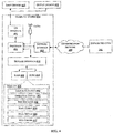
- FIG. 2B illustrates a method of determining predicted energy savings and energy savings target(s) using a modular transfer function.
- the energy savings prediction system 107 determines the values of predicted energy savings 237 and energy savings target 239 for each of the one or more distributed sites 101 by performing the modular transfer function 235 on the one or more energy coefficients 213.
- the predicted energy savings 237 may be determined by evaluating a first set of energy coefficients 213 1 , which are generated by the coefficient generation module 223 using the historic and current values of the one or more operational parameters 211 during the baseline period.
- the energy savings target may be obtained by evaluating a second set of energy coefficients 213 2 that are obtained by performing machine learning techniques on the values of the one or more operational parameters 211 at the reporting period, using the machine learning component 233.
- the machine learning component 233 may use the historic and the current values of the one or more operational parameters data to determine the energy savings target for a pre-set target value.
- the pre-set target value may be 10%, which means that the energy savings target is 10% higher than the median energy savings value in the one or more distributed sites 101.
- One or more coefficients of the modular transfer function 235 may be identified by iteratively operating on the initial values of the one or more coefficients. An initial guess on the values of the one or more coefficients is made in order to find the values that are reasonably close to the true root. Then the modular transfer function 235 may be approximated by its tangent line, which may be computed using the tools of calculus, and by computing x- intercept of the tangent line using elementary algebra techniques.
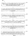
- FIG. 3 shows a flowchart illustrating a method for determining the energy savings target for the one or more distributed sites.
- the method 300 comprises one or more blocks for determining energy savings target for one or more distributed sites 101 using an energy savings prediction system 107.
- the method 300 may be described in the general context of computer executable instructions.
- computer executable instructions can include routines, programs, objects, components, data structures, procedures, modules, and functions, which perform particular functions or implement particular abstract data types.
- the energy savings prediction system 1Q7 identifies one or more energy profiles 211 at each of one or more distributed sites 101 by defining a service window and one or more energy control measures associated with the service window.
- the one or more energy profiles 211 are identified by mapping the service window with each of the one or more distributed sites 101 based on operating schedule of each of the one or more distributed sites 101.
- the energy savings prediction system 107 determines values of each of one or more operational parameters for a baseline period against a target reporting period in each of the one or more energy profiles 211.
- the one or more operational parameters include, without limiting to, rate of energy consumption at each of the distributed sites 101, business volume of each of the distributed sites 101, weather related data, equipment usage data and so forth.
- the energy savings prediction system 107 computes one or more energy coefficients 213 by performing one or more energy optimization techniques on the values of each of the one or more operational parameters.
- the values of each of the one or more operational parameters are normalized to a predefined time period using modular transfer functions 235 and coefficients of the modular transfer functions 235.
- the energy savings prediction system 107 predicts energy consumption of the one or more distributed sites 101 in the service window by performing modular transformation of the one or more energy coefficients 213.
- the values of the one or more energy coefficients 213 are updated during each reporting period while predicting the energy consumption.
- the energy savings prediction system 107 computes a current energy savings at each of the one or more distributed sites 101 based on the energy consumption thus predicted and one or more adjustment factors.
- the one or more adjustment factors include at least one of manual override adjustment factor, back failure control adjustment factor, operating schedule adjustment factor and out of boundary adjustment factor.
- the energy savings prediction system 107 determines the energy savings target for each of the one or more distributed sites 101 by performing the modular transformation of the one or more energy coefficients 213 when compared with the current energy savings. Finally, the energy savings prediction system 107 displays information comprising at least one of energy consumption values at each of the one or more distributed sites 101, the current energy savings value and the energy savings target on a user interface 109 associated with the energy savings prediction system 107.
- FIG. 4 illustrates a block diagram of an exemplary computer system 400 for implementing embodiments consistent with the present invention.
- the computer system 400 may be the energy savings prediction system 107 which is used for determining energy savings target for one or more distributed sites 101 of an entity.
- the computer system 400 may comprise a central processing unit ("CPU” or "processor") 402.
- the processor 402 may comprise at least one data processor for executing program components for executing user or system-generated business processes.
- a user may include a person, a person using a device such as such as those included in this invention, or such a device itself.
- the processor 402 may include specialized processing units such as integrated system (bus) controllers, memory management control units, floating point units, graphics processing units, digital signal processing units, etc.
- the processor 402 may be disposed in communication with one or more input/output (I/O) devices (411 and 412) via I/O interface 401.
- the I/O interface 401 may employ communication protocols/methods such as, without limitation, audio, analog, digital, stereo, IEEE-1394, serial bus, Universal Serial Bus (USB), infrared, PS/2, BNC, coaxial, component, composite, Digital Visual Interface (DVI), high-definition multimedia interface (HDMI), Radio Frequency (RF) antennas, S-Video, Video Graphics Array (VGA), IEEE 802.n /b/g/n/x, Bluetooth, cellular (e.g., Code-Division Multiple Access (CDMA), High-Speed Packet Access (HSPA+), Global System For Mobile Communications (GSM), Long-Term Evolution (LTE) or the like), etc.
- CDMA Code-Division Multiple Access
- HSPA+ High-Speed Packet Access
- GSM Global System For Mobile Communications
- LTE Long-Term Evolution
- the computer system 400 may communicate with one or more I/O devices (411 and 412).
- the processor 402 may be disposed in communication with a communication network 409 via a network interface 403.
- the network interface 403 may communicate with the communication network 409.
- the network interface 403 may employ connection protocols including, without limitation, direct connect, Ethernet (e.g., twisted pair 10/100/1000 Base T), Transmission Control Protocol/Internet Protocol (TCP/IP), token ring, IEEE 802.1 la/b/g/n/x, etc.
- TCP/IP Transmission Control Protocol/Internet Protocol
- token ring IEEE 802.1 la/b/g/n/x, etc.
- the computer system 400 may communicate with the one or more distributed sites 101 for collecting/receiving the one or more operational parameters associated with the one or more distributed sites 101.
- the communication network 409 can be implemented as one of the different types of networks, such as intranet or Local Area Network (LAN) and such within the organization.
- LAN Local Area Network
- the communication network 409 may either be a dedicated network or a shared network, which represents an association of the different types of networks that use a variety of protocols, for example, Hypertext Transfer Protocol (HTTP), Transmission Control Protocol/Internet Protocol (TCP/IP), Wireless Application Protocol (WAP), etc., to communicate with each other. Further, the communication network 409 may include a variety of network devices, including routers, bridges, servers, computing devices, storage devices, etc.
- HTTP Hypertext Transfer Protocol
- TCP/IP Transmission Control Protocol/Internet Protocol
- WAP Wireless Application Protocol
- the communication network 409 may include a variety of network devices, including routers, bridges, servers, computing devices, storage devices, etc.
- the processor 402 may be disposed in communication with a memory 405 (e.g., RAM 413, ROM 414, etc. as shown in FIG. 4 ) via a storage interface 404.
- the storage interface 404 may connect to memory 405 including, without limitation, memory drives, removable disc drives, etc., employing connection protocols such as Serial Advanced Technology Attachment (SATA), Integrated Drive Electronics (IDE), IEEE-1394, Universal Serial Bus (USB), fiber channel, Small Computer Systems Interface (SCSI), etc.
- the memory drives may further include a drum, magnetic disc drive, magnetooptical drive, optical drive, Redundant Array of Independent Discs (RAID), solid-state memory devices, solid-state drives, etc.
- the memory 405 may store a collection of program or database components, including, without limitation, user/application data 406, an operating system 407, web server 408 etc.
- computer system 400 may store user/application data 406, such as the data, variables, records, etc. as described in this invention.
- databases may be implemented as fault-tolerant, relational, scalable, secure databases such as Oracle or Sybase.
- the operating system 407 may facilitate resource management and operation of the computer system 400.
- Examples of operating systems include, without limitation, Apple Macintosh OS X, UNIX, Unix-like system distributions (e.g., Berkeley Software Distribution (BSD), FreeBSD, Net BSD, Open BSD, etc.), Linux distributions (e.g., Red Hat, Ubuntu, K- Ubuntu, etc.), International Business Machines (IBM) OS/2, Microsoft Windows (XP, Vista/7/8, etc.), Apple iOS, Google Android, Blackberry Operating System (OS), or the like.
- a user interface may facilitate display, execution, interaction, manipulation, or operation of program components through textual or graphical facilities.
- GUIs may provide computer interaction interface elements on a display system operatively connected to the computer system 400, such as cursors, icons, check boxes, menus, windows, widgets, etc.
- Graphical User Interfaces may be employed, including, without limitation, Apple Macintosh operating systems' Aqua, IBM OS/2, Microsoft Windows (e.g., Aero, Metro, etc.), Unix X-Windows, web interface libraries (e.g., ActiveX, Java, JavaScript, AJAX, HTML, Adobe Flash, etc.), or the like.
- the computer system 400 may implement a web browser 408 stored program component.
- the web browser may be a hypertext viewing application, such as Microsoft Internet Explorer, Google Chrome, Mozilla Firefox, Apple Safari, etc. Secure web browsing may be provided using Secure Hypertext Transport Protocol (HTTPS) secure sockets layer (SSL), Transport Layer Security (TLS), etc. Web browsers may utilize facilities such as AJAX, DHTML, Adobe Flash, JavaScript, Java, Application Programming Interfaces (APIs), etc.
- the computer system 400 may implement a mail server stored program component.
- the mail server may be an Internet mail server such as Microsoft Exchange, or the like.
- the mail server may utilize facilities such as Active Server Pages (ASP), ActiveX, American National Standards Institute (ANSI) C++/C#, Microsoft .NET, CGI scripts, Java, JavaScript, PERL, PHP, Python, WebObjects, etc.
- the mail server may utilize communication protocols such as Internet Message Access Protocol (IMAP), Messaging Application Programming Interface (MAPI), Microsoft Exchange, Post Office Protocol (POP), Simple Mail Transfer Protocol (SMTP), pr the like.
- the computer system 400 may implement a mail client stored program component.
- the mail client may be a mail viewing application, such as Apple Mail, Microsoft Entourage, Microsoft Outlook, Mozilla Thunderbird, etc.
- a computer-readable storage medium refers to any type of physical memory on which information or data readable by a processor may be stored.
- a computer-readable storage medium may store instructions for execution by one or more processors, including instructions for causing the processor(s) to perform steps or stages consistent with the embodiments described herein.
- the term "computer- readable medium” should be understood to include tangible items and exclude carrier waves and transient signals, i.e., non-transitory. Examples include Random Access Memory (RAM), Read- Only Memory (ROM), volatile memory, nonvolatile memory, hard drives, Compact Disc (CD) ROMs, Digital Video Disc (DVDs), flash drives, disks, and any other known physical storage media.
- the present disclosure provides a system and a method for computing and determining the energy savings target(s) for a network of distributed sites, such as different operational branches of a bank, where operational energy efficiency measures are deployed.
- the method of present disclosure helps in tracking the effectiveness of the results of energy control measures performed on the distributed sites over a multi-year period.
- the present disclosure teaches a method for determining routine and/or non-routine based adjustments while performing the energy savings calculations for the distributed sites.
- the method of present disclosure facilitates in determining site level overrides solution and meeting business needs when the operational savings measures on the distributed sites need to be disabled.
- the present disclosure discloses a unique framework to depict the energy consumptions of the distributed sites using transfer functions and local & global estimation processes.
- an embodiment means “one or more (but not all) embodiments of the invention(s)" unless expressly specified otherwise.
- Reference Numerals Reference Number Description 100 Environment 101 Distributed sites 103 Energy Management Gateway (EMG) 103a Business logic in EMG 103b Network interfaces in EMG 105 Communication network 107 Energy savings prediction system 109 User interface 201 I/O Interface 203 Processor 205 Memory 207 Data 209 Modules 211 Energy profiles 213 Energy coefficients 215 Other data 217 Receiving module 219 Baseline period module 221 Reporting period module 223 Coefficient generation module 227 Adjustment module 229 Energy savings computation module 231 Other modules 233 Machine learning component 235 Modular transfer function 237 Predicted energy savings 239 Energy savings target
Landscapes
- Engineering & Computer Science (AREA)
- Business, Economics & Management (AREA)
- Economics (AREA)
- General Physics & Mathematics (AREA)
- Physics & Mathematics (AREA)
- Human Resources & Organizations (AREA)
- Strategic Management (AREA)
- Theoretical Computer Science (AREA)
- Tourism & Hospitality (AREA)
- Entrepreneurship & Innovation (AREA)
- Marketing (AREA)
- General Business, Economics & Management (AREA)
- Health & Medical Sciences (AREA)
- Quality & Reliability (AREA)
- Operations Research (AREA)
- Game Theory and Decision Science (AREA)
- Educational Administration (AREA)
- Development Economics (AREA)
- Public Health (AREA)
- Water Supply & Treatment (AREA)
- General Health & Medical Sciences (AREA)
- Primary Health Care (AREA)
- Automation & Control Theory (AREA)
- General Engineering & Computer Science (AREA)
- Management, Administration, Business Operations System, And Electronic Commerce (AREA)
Abstract
Description
- The present subject matter is related, in general to energy conservation, and more particularly, but not exclusively to a method and system for determining energy savings target(s) for one or more distributed sites of an entity.
- Currently, energy savings from various energy conservation projects is measured and verified using an International Performance Measurement and Verification Protocol (IPMVP) framework. The IPMVP was developed by a coalition of international organizations (led by the United States Department of Energy) in 1994-1995. Now, the IPMVP has become a national measurement and verification standard in some of the countries, including the United States, and has been translated into 10 languages. The IPMVP framework offers four specific options for quantifying the energy savings. The IPMVP suggests best practices for quantifying the results of energy efficiency investments. The IPMVP also helps in increasing investments in energy and water management, demand management and renewable energy projects.
- The specific options provided by the IPMVP framework for estimating the energy consumption/savings in a site (A, B, C and D) are summarized as shown below:
- Here, the energy savings are determined by field measurement of the key performance parameter(s) which defines the energy use of the energy conservation measure's (ESS) affected system(s) and/or the success of the project. The energy estimates are derived based on historical data, manufacturer's specifications, or engineering judgment. Documentation of the source or justification of the estimated parameter is required. Typical applications of performing retrofit isolation of key parameters may include a lighting retrofit, where the power drawn can be monitored and hours of operation can be estimated.
- Here, the energy savings are determined by field measurement of all the key performance parameters which define the energy use of the ESS-affected system. Typical applications may include a lighting retrofit where both power drawn and hours of operation are recorded.
- Here, the energy savings are determined by measuring energy use at the whole facility or sub-facility level. This approach is likely to require a regression analysis or similar to account for independent variables such as outdoor air temperature, for example. Typical examples may include measurement of a facility where several ESSs have been implemented, or where the ESS is expected to affect all equipment in a facility.
- Here, the energy savings are determined through simulation of the energy use of the whole facility, or of a sub-facility. Simulation routines are demonstrated to adequately model actual energy performance measured in the facility. This Option usually requires considerable skill in calibrated simulation. Typical applications may include measurement of a facility where several ESSs have been implemented, but no historical energy data is available
- However, IPMVP methodologies summarized above are best suited only for those retrofits in which some assets are replaced or modified. Instead, the retrofits in which energy savings are generated purely on account of operational ESS, like schedule management, set-point management, asset performance management, capacity management etc., the above methodologies are not suitable.
- Also, the IPMVP methodologies may not be suitable for estimation of energy consumption in the distributed sites that involve variations in several other parameters like sales, age of the asset, ambient temperature, operating hours in different day of week etc. Further, in certain circumstances, the energy consumption across the distributed sites may go up due to higher business intensity in the service window irrespective of the energy control measures.
- The challenges mainly faced during determining energy savings targets for the distributed sites of an entity includes generating energy coefficients associated with an energy profile of the distributed sites and computing energy savings across the distributed based on the energy coefficients and adjustment factors.
- Disclosed herein is a method for determining energy savings target(s) for one or more distributed sites of an entity. The method comprises identifying, by an energy savings prediction system, one or more energy profiles at each of one or more distributed sites by defining a service window and one or more energy control measures associated with the service window. Values of each of one or more operational parameters are determined for a baseline period against a target reporting period in each of the one or more energy profiles. Upon determining the values of the one or more operational parameters, one or more energy coefficients are computed by performing one or more energy optimization techniques on the values of each of the one or more operational parameters. Further, energy consumption in the service window is predicted by performing modular transformation of the one or more energy coefficients. A current energy savings value at each of the one or more distributed sites is computed based on the energy consumption thus predicted and one or more adjustment factors. Finally, the energy savings target(s) for each of the one or more distributed sites is determined by performing the modular transformation of the one or more energy coefficients when compared with the current energy savings.
- Further, the present disclosure discloses an energy savings prediction system for determining energy savings target(s) for one or more distributed sites of an entity. The energy savings prediction system comprises a processor and a memory. The memory is communicatively coupled to the processor and stores processor-executable instructions, which, on execution, causes the processor to identify one or more energy profiles at each of one or more distributed sites by defining a service window and one or more energy control measures associated with the service window. Upon identifying the one or more energy profiles, values of each of one or more operational parameters are determined for a baseline period against a target reporting period in each of the one or more energy profiles. The processor computes one or more energy coefficients by performing one or more energy optimization techniques on the values of each of the one or more operational parameters. Further, the processor predicts energy consumption in the service window by performing modular transformation of the one or more energy coefficients. Furthermore, the processor computes current energy savings at each of the one or more distributed sites based on the energy consumption thus predicted and one or more
adjustment factors. Finally, the processor determines the energy savings target(s) for each of the one or more distributed sites by performing the modular transformation of the one or more energy coefficients when compared with the current energy savings. - The foregoing summary is illustrative only and is not intended to be in any way limiting. In addition to the illustrative aspects, embodiments, and features described above, further aspects, embodiments, and features will become apparent by reference to the drawings and the following detailed description.
- The accompanying drawings, which are incorporated in and constitute a part of this disclosure, illustrate exemplary embodiments and, together with the description, serve to explain the disclosed principles. In the figures, the left-most digit(s) of a reference number identifies the figure in which the reference number first appears. The same numbers are used throughout the figures to reference like features and components. Some embodiments of system and/or methods in accordance with embodiments of the present subject matter are now described, by way of example only, and with reference to the accompanying figures, in which:
-
FIG. 1 shows an exemplary environment for determining energy savings target(s) for one or more distributed sites of an entity using an energy savings prediction system; -
FIG. 2A shows a detailed block diagram illustrating the energy savings prediction system; -
FIG. 2B illustrates a method of determining predicted energy savings and energy savings target(s) using a modular transfer function; -
FIG. 3 shows a flowchart illustrating a method for determining the energy savings target(s) for the one or more distributed sites; and -
FIG. 4 illustrates a block diagram of an exemplary computer system for implementing embodiments consistent with the present disclosure. - It should be appreciated by those skilled in the art that any block diagrams herein represent conceptual views of illustrative systems embodying the principles of the present subject matter. Similarly, it will be appreciated that any flow charts, flow diagrams, state transition diagrams, pseudo code, and the like represent various processes which may be substantially represented in computer readable medium and executed by a computer or processor, whether or not such computer or processor is explicitly shown.
- In the present document, the word "exemplary" is used herein to mean "serving as an example, instance, or illustration." Any embodiment or implementation of the present subject matter described herein as "exemplary" is not necessarily to be construed as preferred or advantageous over other embodiments.
- While the disclosure is susceptible to various modifications and alternative forms, specific embodiment thereof has been shown by way of example in the drawings and will be described in detail below. It should be understood, however that it is not intended to limit the disclosure to the particular forms disclosed, but on the contrary, the disclosure is to cover all modifications, equivalents, and alternative falling within the spirit and the scope of the disclosure.
- The terms "comprises", "comprising", or any other variations thereof, are intended to cover a non-exclusive inclusion, such that a setup, device or method that comprises a list of components or steps does not include only those components or steps but may include other components or steps not expressly listed or inherent to such setup or device or method. In other words, one or more elements in a system or apparatus proceeded by "comprises... a" does not, without more constraints, preclude the existence of other elements or additional elements in the system or method.
- The present disclosure relates to a method and an energy savings prediction system for determining energy savings target(s) for one or more distributed sites of an entity. The energy savings prediction system of the present disclosure computes and compiles the energy savings at a site, rolling up into a network of distributed sites, using a bottom-to-top approach. The energy savings prediction system is a unique model framework for depicting the energy consumption across the network of distributed sites. The system defines a baseline period and one or more consecutive reporting periods for computing the energy savings across the distributed sites by performing modular transformation of energy coefficients associated with a service window of the distributed sites. The energy coefficients associated with the service window may be computed by leveraging predetermined local and global energy estimation processes in the baseline period and the reporting period.
- The energy savings prediction system defines a set of operational Energy Savings Strategies (ESS) that are applicable for each service window and each type of asset/instrumentation within the distributed sites. The system leverages the ESS onto the service window of the distributed sites and achieves energy control measures through schedule management, set-point management, asset performance management, capacity management etc. Further, the energy savings prediction system may also deploy instrumentation such as, energy meters, temperature sensors, thermostats etc. onto the distributed sites in order to measure and record parameter changes like energy consumption rate, temperature and operational parameters.
- In an embodiment, the method and the energy savings prediction system of the present disclosure may define a set of site-level operational override solutions to meet the business needs of the distributed sites when some of the operational savings measures in the distributed sites have to be disabled. The energy savings prediction system achieves the site-level operational overrides by applying various adjustment factors in the consecutive reporting periods of the distributed sites, thereby clearly distinguishing the energy effects of the energy control measures from the energy effects resulting from other simultaneous changes in the distributed sites.
- In the following detailed description of the embodiments of the disclosure, reference is made to the accompanying drawings that form a part hereof, and in which are shown by way of illustration specific embodiments in which the disclosure may be practiced. These embodiments are described in sufficient detail to enable those skilled in the art to practice the disclosure, and it is to be understood that other embodiments may be utilized and that changes may be made
without departing from the scope of the present disclosure. The following description is, therefore, not to be taken in a limiting sense. -
FIG. 1 shows an exemplary environment for determining energy savings target(s) for one or more distributed sites of an entity using an energy savings prediction system. - Accordingly, the
environment 100 comprises one or more distributedsites 101, distributedsite 1 101i to distributed site n 101n (collectively referred as distributed sites 101) of an entity, an Energy Management Gateway (EMG) 103 and an energysavings prediction system 107. TheEMG 103 may be configured with abusiness logic 103a and network interfaces lQ3b. Thebusiness logic 103a may include set of real-world business rules and strategies that determine the business related operations of the entity. In an embodiment, each of the one or more distributedsites 101 Of the entity may be adapted to different set of business rules based on the business requirements at the one or more distributedsites 101. - The network interfaces 103b are used to establish a communication between the
EMG 103 and the energysavings prediction system 107 through thecommunication network 105. As an example, the one ormore network interfaces 103b may includc, without limiting to, wireless communication interfaces like Wi-Fi, Zig Bee, along with packet oriented mobile network services like GSM/GPRS, wired communication interfaces like Ethernet and so forth. Thecommunication network 105 may be one of a wired communication line, wireless communication channel or any combination thereof, that enable communication between theEMG 103 and the energysavings prediction system 107. - In an embodiment, the energy
savings prediction system 107 may receive data related to one or more operational parameters from the one or more distributedsites 101 through theEMG 103 andcommunication network 105. As an example, the one or more operational parameters include, without limiting to, rate of energy consumption at each of the distributedsites 101, business volume of each of the distributedsites 101, weather related data, equipment usage data, operational manuals of the one or more distributedsites 101 and so forth. Upon receiving the data related to the one or more operational parameters, the energysavings prediction system 107 may generate one ormore energy coefficients 213 by performing one or more energy
optimization techniques on the values of each of the one or more operational parameters. Further, the energysavings prediction system 107 may predict energy consumption in a service window of the one or more distributedsites 101 by performing modular transformation of the one ormore energy coefficients 213. Finally, the energysavings prediction system 107 determines the energy savings target(s) for each of the one or more distributedsites 101 by performing the modular transformation of the one ormore energy coefficients 213 when compared with a current energy savings value across the one or more distributedsites 101. In an embodiment, the energysavings prediction system 107 may display various information, including the values of the energy consumption and the energy savings target(s), on a display interface associated with the energysavings prediction system 107. -
FIG. 2A shows a detailed block diagram illustrating the energy savings prediction system. - The energy
savings prediction system 107 comprises an I/O interface 201, a processor 2Q3 and amemory 205. The I/O interface 201 may be configured to receive the one or more operational parameters from the one or more distributedsites 101 through thecommunication network 105. Thememory 205 may be communicatively coupled to theprocessor 203. Theprocessor 203 may be configured to perform one or more functions of the energysavings prediction system 107 for determining the energy savings target for the one or more distributedsites 101. In an implementation, the energysavings prediction system 107 may comprisedata 207 andmodules 209 for performing various operations in accordance with the embodiments of the present disclosure. In an embodiment, thedata 207 may be stored within thememory 205 and may include, without limiting to, one ormore energy profiles 211 associated with the one or more distributedsites 101, the one ormore energy coefficients 213 andother data 215. - The
data 207 may be stored within thememory 205 in the form of various data structures. Additionally, theaforementioned data 207 may be organized using data models, such as relational or hierarchical data models. Theother data 215 may store data, including temporary data and temporary files, generated bymodules 209 while performing the various functions of the energysavings prediction system 107. - The one or
more energy profiles 211 associated with the one or more distributedsites 101 are identified by the energysavings prediction system 107 by mapping a service window associated with each of the one or more distributedsites 101 with the one or more distributedsites 101 based on operating schedule of each of the one or more distributedsites 101. The service window is a framework that helps in identifying theunique energy profiles 211 that each of the one or more distributedsites 101 go through during their operation. The energy profiles 211 of each of the one or more distributedsites 101 are a result of the business volume, weather, equipment usage, operational menu etc. operational parameters associated with the one or more distributedsites 101. As an example, theenergy profile 211 for a construction site may include patterns/timelines of different operations in the construction site, such as crew set-up, breakfast, pre-lunch, lunch, post-lunch and dinner. Similarly, theenergy profile 211 for a bank may include details of bank set-up hours, customer hours, closing hours and maintenance hours of the bank. In an embodiment, theenergy profiles 211 associated with each of the one or more distributedsites 101 may be different and defined based on business requirements across each of the one or more distributedsites 101. - The one or
more energy coefficients 213 arc computed by the energysavings prediction system 107 by performing one or more energy optimization techniques on the values of each of the one or more operational parameters. As an example, the one or more energy optimization techniques used for computing the one ormore energy coefficients 213 may be a local optimization technique such as Least Squares (LS) optimization or a global optimization technique such as Principle Component Analysis (PCA). In an embodiment, the energysavings prediction system 107 leverages the one or more energy optimization techniques on the historic and/or current values of the one or more operational parameters. - The
data 207 may be processed by one ormore modules 209 of the energysavings prediction system 107. In one implementation, the one ormore modules 209 may be stored as a part of theprocessor 203. In another implementation, the one ormore modules 209 may be communicatively coupled to theprocessor 203 for performing one or more functions of the energysavings prediction system 107. Themodules 209 may include, without limiting to, a receivingmodule 217, abaseline period module 219, areporting period module 221, acoefficient generation module 223, an adjustment module 227, an energysavings computation module 229 andother modules 231. - As used herein, the term module refers to an application specific integrated circuit (ASIC), an electronic circuit, a processor (shared, dedicated, or group) and memory that execute one or more software or firmware programs, a combinational logic circuit, and/or other suitable components that provide the described functionality. In an embodiment, the
other modules 231 may be used to perform various miscellaneous functionalities of the energysavings prediction system 107. It will be appreciated that such aforementioned modules may be represented as a single module or a combination of different modules. - The receiving
module 217 may be responsible for receiving the data related to the one or more operational parameters from the one or more distributedsites 101. In an implementation, the receivingmodule 217 may communicate with a data measurement component (not shown in figures), deployed at each of the one or more distributedsites 101, to receive the data related to the one or more operational parameters through thecommunication network 105. The data measurement component may be configured to record and transmit the values of the one or more operational parameters required for computing and determining the energy savings target. The data measurement component may collect the values of the one or more operational parameters from various instruments including energy monitoring/relay devices, grid meters, Distributed Generation (PG) meters, temperature sensors/ transducers and so forth that are deployed in each of the one or more distributedsites 101. - The receiving
module 217 may receive the data related to the one or more operational parameters in the form of data packets using TCP/IP data transmission protocol. Further, the receivingmodule 217 may translate the received data, which is in the hexadecimal data format, to a user-readable data format. Then the translated data are stored in the energysavings prediction system 107 for defining values of the one or more operational parameters during a baseline period against a target reporting period. - The
baseline period module 219 may be responsible for defining a baseline period for determining the values of the one or more operational parameters. The baseline period for each of the one or more distributedsites 101 may be configurable individually based on the operational schedule of the one or more distributedsites 101. Initially, thebaseline period module 219 may identify the historic values of the one or more operational parameters over a predetermined period of operation, for example, one year. Then, thebaseline period module 219 may normalize the identified values of the one or more operational parameters into a predefined time period usingmodular transfer functions 235 and coefficients of the modular transfer functions 235. As an example, the predefined time period of normalization may be in terms of number of months, weeks or days of operation of the one or more distributedsites 101. In an embodiment, thebaseline period module 219 may compute sales/guest count data over the predefined time period from daily or weekly format. - The
reporting period module 221 may be responsible for defining a target reporting period, against which the values of each of one or more operational parameters for the baseline period have to be determined. Similar to the baseline period, the reporting period for each of the one or more distributedsites 101 may be configurable individually based on the operational schedule of the one or more distributedsites 101. Initially, thereporting period module 221 may identify the current values of the one or more operational parameters across each of the one or more distributedsites 101. Then, thereporting period module 221 may normalize the identified values of the one or more operational parameters into a predefined time period usingmodular transfer functions 235 and coefficients of the modular transfer functions 235. As an example, the predefined time period of normalization may be in terms of number of months, weeks or days of operation of the one or more distributedsites 101. In an embodiment, thereporting period module 219 may compute sales/guest count data over the predefined time period from daily or weekly format. - Both the
baseline period module 219 and thereporting period module 221 may consider total number of days that the one or more distributedsites 101 were shut down or no operations were performed, during normalization of the identified data. Consideration of the discretionary shut down days of the one or more distributedsites 101 helps in accurate calculations of the values of energy consumption and energy savings at each of the one or more distributedsites 101. - The
coefficient generation module 223 may be responsible for generating and computing the one ormore energy coefficients 213 associated with theenergy profiles 211 of the one or more distributedsites 101. In some embodiment, thecoefficients generation module 223 may generate the one ormore energy coefficients 213 by iteratively minimizing Euclidean distance between the actual value as well as the predicted values of the energy consumption/savings. - The
coefficient generation module 223 may take the values of the one or more operational parameters in the baseline period and the reporting period and perform one or more local and/or global optimization techniques to estimate the one ormore energy coefficients 213 related to the one or more operational parameters. As an example, the initial estimation of the one ormore energy coefficients 213 may be derived using the local optimization technique such as, the Least Square (LS) regression optimization technique. Further, the initial estimation of the one ormore energy coefficients 213 may be further refined by using a fitness function or a gradient solving technique like Newton Raphson method to estimate the one ormore energy coefficients 213. - The
coefficient generation module 223 may converge the one ormore energy coefficients 213 to a local minimum value before further optimizing the one ormore energy coefficients 213 using the global optimization tools such as Particle Swarm Optimization (PQS). The POS optimization may be performed using the coefficients from the gradient solver technique as an initial guess to ensure that the one ormore energy coefficients 213 are converged to a global minimum and a least residual values. - The adjustment module 227 may be responsible for determining the values corresponding to the one or more adjustment factors that have to be considered while predicting the energy consumption value across each of the one or more distributed
sites 101. As an example, the one or more adjustment factors include at least one of manual override adjustment factor, back failure control adjustment factor, operating schedule adjustment factor and out of boundary adjustment factor, which are explained in detail in the below paragraphs: - Because of the site-specific business requirements, some of the operational measures may have to be disabled for a predetermined time period- For this, each of the one or more distributed
sites 101 may be provided with a physical/manual override component to override the operational efficiency measures for the predetermined time period for required asset groups like lighting. The manual override component may be purely based on the site manager's discretion. The energy consumption that happens because of the manual override has to be factored from each reporting period as an adjustment. - The control back failure adjustments have to be performed when the site-level controls fail because of issues, for example, break-down of instruments in the site. In such situations, the energy consumption because of the control back failure have to be factored as adjustments while computing the energy savings value.
- Any changes in the business schedules of the one or more distributed
sites 101, for example, major changes in the site's business hours, may have to be taken into account while computing the energy consumption/savings values for the one or more distributedsites 101. - Significant additions or modifications in out of boundary loads, for example, power consumption from an isolated meter, have to be considered as adjustment to the baseline energy consumption values for an accurate estimation of the energy consumption across each of the one or more distributed
sites 101. - The one or more adjustments may have to be carried out in order to segregate the energy effects of one of the energy savings measures from the effects of other simultaneous changes affecting the values of energy consumption and/or savings across the one or more distributed
sites 101. Thus, the adjustment module 227 helps the energysavings prediction system 107 to adapt to the routine and non-routine based adjustments factors that are disclosed above. - The energy
savings computation module 229 may be responsible for computing current energy savings at each of the one or more distributedsites 101 based on the energy consumption at each of the one or more distributedsites 101 and one or more adjustment factors. The energy consumption at each of the one or more distributedsites 101 may be computed by performing modular transformation of the one ormore energy coefficients 213. Equation (1) below is an exemplary illustration of computation of monthly energy consumption in one of the distributedsites 101.
- Where, CO, C1, C2, C3, C4, D1, D2, D3 and E1 represent energy coefficients associated with the distributed
site 101. Each of these energy coefficients may be computed using one or more local and/or global optimization techniques. The parameters cCDD' and 'HDD' in equation (1) indicate the energy consumption variations with respect to Cooling Degree Days (CDD) and Heating Degree Days (HDD) at the distributedsite 101. - Upon computing the energy consumption values, the energy
savings computation module 229 may compute energy savings for each service window of the one or more distributedsites 101 on single day basis and then compute the total energy savings based on the number of weekdays in the reporting period of each of the one or more distributedsites 101. In an embodiment, the energy savings for each of the one or more distributedsites 101 may be calculated using the following equation:
- The energy
savings computation module 229 may collect and compile the energy savings of each of the one or more distributedsites 101 for a number of reporting periods based on different levels, for example enterprise level, cluster/city level, site level and asset level, in the one or more distributedsites 101. The collected energy savings values of the one or more
distributedsites 101 may be used for determining the energy savings target for each of the one or more distributedsites 101. In an embodiment, the energysavings computation module 229 determines the energy savings target for each of the one or more distributedsites 101 by performing the modular transformation of the one ormore energy coefficients 213 when compared with the energy savings at each of the one or more distributedsites 101 over a number of reporting periods. - The energy
savings computation module 229 may be communicably coupled to a User Interface (UI) 109 for displaying various information comprising, without limiting to, the energy consumption values at each of the one or more distributedsites 101, the current energy savings value and the energy savings target for each of the one or more distributedsites 101. The UI 109 may display the above information in various display formats such as, tables, pie charts, trends, and graphs and may allow the users to download the displayed information for future use. The information being displayed on the UI 109 may be categorized as per different levels in the one or more distributedsites 101. In an embodiment, the UI 109 may also be configured to provide one or more energy savings recommendations to the user. As an example, the UI 109 may indicate/highlight a critical energy control measure from the information being displayed, in order to draw the attention of the users onto the critical energy control measure. In an implementation, the UI 109 may be configured within the energysavings prediction system 107. -
FIG. 2B illustrates a method of determining predicted energy savings and energy savings target(s) using a modular transfer function. - The energy
savings prediction system 107 determines the values of predictedenergy savings 237 and energy savings target 239 for each of the one or more distributedsites 101 by performing themodular transfer function 235 on the one ormore energy coefficients 213. In an embodiment, the predictedenergy savings 237 may be determined by evaluating a first set ofenergy coefficients 2131, which are generated by thecoefficient generation module 223 using the historic and current values of the one or moreoperational parameters 211 during the baseline period. Similarly, the energy savings target may be obtained by evaluating a second set of energy
coefficients 2132 that are obtained by performing machine learning techniques on the values of the one or moreoperational parameters 211 at the reporting period, using themachine learning component 233. - The
machine learning component 233 may use the historic and the current values of the one or more operational parameters data to determine the energy savings target for a pre-set target value. As an example, the pre-set target value may be 10%, which means that the energy savings target is 10% higher than the median energy savings value in the one or more distributedsites 101. - One or more coefficients of the
modular transfer function 235 may be identified by iteratively operating on the initial values of the one or more coefficients. An initial guess on the values of the one or more coefficients is made in order to find the values that are reasonably close to the true root. Then themodular transfer function 235 may be approximated by its tangent line, which may be computed using the tools of calculus, and by computing x- intercept of the tangent line using elementary algebra techniques. -
FIG. 3 shows a flowchart illustrating a method for determining the energy savings target for the one or more distributed sites. - As illustrated in
FIG. 3 , themethod 300 comprises one or more blocks for determining energy savings target for one or more distributedsites 101 using an energysavings prediction system 107. Themethod 300 may be described in the general context of computer executable instructions. Generally, computer executable instructions can include routines, programs, objects, components, data structures, procedures, modules, and functions, which perform particular functions or implement particular abstract data types. - The order in which the
method 300 is described is not intended to be construed as a limitation, and any number of the described method blocks can be combined in any order to implement the method. Additionally, individual blocks may be deleted from the methods without departing from the spirit and scope of the subject matter described herein. Furthermore, the
method can be implemented in any suitable hardware, software, firmware, or combination thereof. - At
block 301, the energy savings prediction system 1Q7 identifies one ormore energy profiles 211 at each of one or more distributedsites 101 by defining a service window and one or more energy control measures associated with the service window. In an embodiment, the one ormore energy profiles 211 are identified by mapping the service window with each of the one or more distributedsites 101 based on operating schedule of each of the one or more distributedsites 101. - At
block 303, the energysavings prediction system 107 determines values of each of one or more operational parameters for a baseline period against a target reporting period in each of the one or more energy profiles 211. As an example, the one or more operational parameters include, without limiting to, rate of energy consumption at each of the distributedsites 101, business volume of each of the distributedsites 101, weather related data, equipment usage data and so forth. - At
block 305, the energysavings prediction system 107 computes one ormore energy coefficients 213 by performing one or more energy optimization techniques on the values of each of the one or more operational parameters. In an embodiment, the values of each of the one or more operational parameters are normalized to a predefined time period usingmodular transfer functions 235 and coefficients of the modular transfer functions 235. - At
block 307, the energysavings prediction system 107 predicts energy consumption of the one or more distributedsites 101 in the service window by performing modular transformation of the one ormore energy coefficients 213. The values of the one ormore energy coefficients 213 are updated during each reporting period while predicting the energy consumption. - At
block 309, the energysavings prediction system 107 computes a current energy savings at each of the one or more distributedsites 101 based on the energy consumption thus predicted and one or more adjustment factors. In an embodiment, the one or more adjustment factors include at least one of manual override adjustment factor, back failure control adjustment factor, operating schedule adjustment factor and out of boundary adjustment factor. - At
block 311, the energysavings prediction system 107 determines the energy savings target for each of the one or more distributedsites 101 by performing the modular transformation of the one ormore energy coefficients 213 when compared with the current energy savings. Finally, the energysavings prediction system 107 displays information comprising at least one of energy consumption values at each of the one or more distributedsites 101, the current energy savings value and the energy savings target on a user interface 109 associated with the energysavings prediction system 107. -
FIG. 4 illustrates a block diagram of anexemplary computer system 400 for implementing embodiments consistent with the present invention. In an embodiment, thecomputer system 400 may be the energysavings prediction system 107 which is used for determining energy savings target for one or more distributedsites 101 of an entity. Thecomputer system 400 may comprise a central processing unit ("CPU" or "processor") 402. Theprocessor 402 may comprise at least one data processor for executing program components for executing user or system-generated business processes. A user may include a person, a person using a device such as such as those included in this invention, or such a device itself. Theprocessor 402 may include specialized processing units such as integrated system (bus) controllers, memory management control units, floating point units, graphics processing units, digital signal processing units, etc. - The
processor 402 may be disposed in communication with one or more input/output (I/O) devices (411 and 412) via I/O interface 401. The I/O interface 401 may employ communication protocols/methods such as, without limitation, audio, analog, digital, stereo, IEEE-1394, serial bus, Universal Serial Bus (USB), infrared, PS/2, BNC, coaxial, component, composite, Digital Visual Interface (DVI), high-definition multimedia interface (HDMI), Radio Frequency (RF) antennas, S-Video, Video Graphics Array (VGA), IEEE 802.n /b/g/n/x, Bluetooth, cellular (e.g., Code-Division Multiple Access (CDMA), High-Speed Packet Access (HSPA+), Global System For Mobile Communications (GSM), Long-Term Evolution (LTE) or the like), etc. - Using the I/
O interface 401, thecomputer system 400 may communicate with one or more I/O devices (411 and 412). - The
processor 402 may be disposed in communication with acommunication network 409 via anetwork interface 403. Thenetwork interface 403 may communicate with thecommunication network 409. Thenetwork interface 403 may employ connection protocols including, without limitation, direct connect, Ethernet (e.g., twisted pair 10/100/1000 Base T), Transmission Control Protocol/Internet Protocol (TCP/IP), token ring, IEEE 802.1 la/b/g/n/x, etc. Using thenetwork interface 403 and thecommunication network 409, thecomputer system 400 may communicate with the one or more distributedsites 101 for collecting/receiving the one or more operational parameters associated with the one or more distributedsites 101. Thecommunication network 409 can be implemented as one of the different types of networks, such as intranet or Local Area Network (LAN) and such within the organization. Thecommunication network 409 may either be a dedicated network or a shared network, which represents an association of the different types of networks that use a variety of protocols, for example, Hypertext Transfer Protocol (HTTP), Transmission Control Protocol/Internet Protocol (TCP/IP), Wireless Application Protocol (WAP), etc., to communicate with each other. Further, thecommunication network 409 may include a variety of network devices, including routers, bridges, servers, computing devices, storage devices, etc. - The
processor 402 may be disposed in communication with a memory 405 (e.g.,RAM 413,ROM 414, etc. as shown inFIG. 4 ) via astorage interface 404. Thestorage interface 404 may connect tomemory 405 including, without limitation, memory drives, removable disc drives, etc., employing connection protocols such as Serial Advanced Technology Attachment (SATA), Integrated Drive Electronics (IDE), IEEE-1394, Universal Serial Bus (USB), fiber channel, Small Computer Systems Interface (SCSI), etc. The memory drives may further include a drum, magnetic disc drive, magnetooptical drive, optical drive, Redundant Array of Independent Discs (RAID), solid-state memory devices, solid-state drives, etc. - The
memory 405 may store a collection of program or database components, including, without limitation, user/application data 406, anoperating system 407,web server 408 etc. In some embodiments,computer system 400 may store user/application data 406, such as the data, variables, records, etc. as described in this invention. Such databases may be implemented as fault-tolerant, relational, scalable, secure databases such as Oracle or Sybase. - The
operating system 407 may facilitate resource management and operation of thecomputer system 400. Examples of operating systems include, without limitation, Apple Macintosh OS X, UNIX, Unix-like system distributions (e.g., Berkeley Software Distribution (BSD), FreeBSD, Net BSD, Open BSD, etc.), Linux distributions (e.g., Red Hat, Ubuntu, K- Ubuntu, etc.), International Business Machines (IBM) OS/2, Microsoft Windows (XP, Vista/7/8, etc.), Apple iOS, Google Android, Blackberry Operating System (OS), or the like. A user interface may facilitate display, execution, interaction, manipulation, or operation of program components through textual or graphical facilities. For example, user interfaces may provide computer interaction interface elements on a display system operatively connected to thecomputer system 400, such as cursors, icons, check boxes, menus, windows, widgets, etc. Graphical User Interfaces (GUIs) may be employed, including, without limitation, Apple Macintosh operating systems' Aqua, IBM OS/2, Microsoft Windows (e.g., Aero, Metro, etc.), Unix X-Windows, web interface libraries (e.g., ActiveX, Java, JavaScript, AJAX, HTML, Adobe Flash, etc.), or the like. - The
computer system 400 may implement aweb browser 408 stored program component. The web browser may be a hypertext viewing application, such as Microsoft Internet Explorer, Google Chrome, Mozilla Firefox, Apple Safari, etc. Secure web browsing may be provided using Secure Hypertext Transport Protocol (HTTPS) secure sockets layer (SSL), Transport Layer Security (TLS), etc. Web browsers may utilize facilities such as AJAX, DHTML, Adobe Flash, JavaScript, Java, Application Programming Interfaces (APIs), etc. In some embodiments, thecomputer system 400 may implement a mail server stored program component. The mail server may be an Internet mail server such as Microsoft Exchange, or the like. The mail server may utilize facilities such as Active Server Pages (ASP), ActiveX, American National Standards Institute (ANSI) C++/C#, Microsoft .NET, CGI scripts, Java, JavaScript, PERL, PHP, Python, WebObjects, etc. The mail server may utilize
communication protocols such as Internet Message Access Protocol (IMAP), Messaging Application Programming Interface (MAPI), Microsoft Exchange, Post Office Protocol (POP), Simple Mail Transfer Protocol (SMTP), pr the like. Thecomputer system 400 may implement a mail client stored program component. The mail client may be a mail viewing application, such as Apple Mail, Microsoft Entourage, Microsoft Outlook, Mozilla Thunderbird, etc. - Furthermore, one or more computer-readable storage media may be utilized. A computer-readable storage medium refers to any type of physical memory on which information or data readable by a processor may be stored. Thus, a computer-readable storage medium may store instructions for execution by one or more processors, including instructions for causing the processor(s) to perform steps or stages consistent with the embodiments described herein. The term "computer- readable medium" should be understood to include tangible items and exclude carrier waves and transient signals, i.e., non-transitory. Examples include Random Access Memory (RAM), Read- Only Memory (ROM), volatile memory, nonvolatile memory, hard drives, Compact Disc (CD) ROMs, Digital Video Disc (DVDs), flash drives, disks, and any other known physical storage media.
- In an embodiment, the present disclosure provides a system and a method for computing and determining the energy savings target(s) for a network of distributed sites, such as different operational branches of a bank, where operational energy efficiency measures are deployed.
- In an embodiment, the method of present disclosure helps in tracking the effectiveness of the results of energy control measures performed on the distributed sites over a multi-year period.
- In an embodiment, the present disclosure teaches a method for determining routine and/or non-routine based adjustments while performing the energy savings calculations for the distributed sites.
- In an embodiment, the method of present disclosure facilitates in determining site level overrides solution and meeting business needs when the operational savings measures on the distributed sites need to be disabled.
- In an embodiment, the present disclosure discloses a unique framework to depict the energy consumptions of the distributed sites using transfer functions and local & global estimation processes.
- The terms "an embodiment", "embodiment", "embodiments", "the embodiment", "the embodiments", "one or more embodiments", "some embodiments", and "one embodiment" mean "one or more (but not all) embodiments of the invention(s)" unless expressly specified otherwise.
- The terms "including", "comprising", "having" and variations thereof mean "including but not limited to", unless expressly specified otherwise.
- The enumerated listing of items does not imply that any or all of the items are mutually exclusive, unless expressly specified otherwise.
- The terms "a", "an" and "the" mean "one or more", unless expressly specified otherwise. A description of an embodiment with several components in communication with each other does not imply that all such components are required. On the contrary a variety of optional components are described to illustrate the wide variety of possible embodiments of the invention.
- When a single device or article is described herein, it will be readily apparent that more than one device/article (whether or not they cooperate) may be used in place of a single device/article. Similarly, where more than one device or article is described herein (whether or not they cooperate), it will be readily apparent that a single device/article may be used in place of the more than one device or article or a different number of devices/articles may be used instead of the shown number of devices or programs. The functionality and/or the features of a device may be alternatively embodied by one or more other devices which are not explicitly described as having such functionality/features. Thus, other embodiments of the invention need not include the device itself.
- Finally, the language used in the specification has been principally selected for readability and instructional purposes, and it may not have been selected to delineate or circumscribe the inventive subject matter. It is therefore intended that the scope of the invention be limited not by this detailed description, but rather by any claims that issue on an application based here on. Accordingly, the embodiments of the present invention are intended to be illustrative, but not limiting, of the scope of the invention, which is set forth in the following claims.
- While various aspects and embodiments have been disclosed herein, other aspects and embodiments will be apparent to those skilled in the art. The various aspects and embodiments disclosed herein are for purposes of illustration and are not intended to be limiting, with the true scope of the invention being indicated by the following claims.
Reference Numerals: Reference Number Description 100 Environment 101 Distributed sites 103 Energy Management Gateway (EMG) 103a Business logic in EMG 103b Network interfaces in EMG 105 Communication network 107 Energy savings prediction system 109 User interface 201 I/ O Interface 203 Processor 205 Memory 207 Data 209 Modules 211 Energy profiles 213 Energy coefficients 215 Other data 217 Receiving module 219 Baseline period module 221 Reporting period module 223 Coefficient generation module 227 Adjustment module 229 Energy savings computation module 231 Other modules 233 Machine learning component 235 Modular transfer function 237 Predicted energy savings 239 Energy savings target
Claims (12)
- A method for determining energy savings target(s) for one or more distributed sites (101) of an entity, the method comprising:identifying, by an energy savings prediction system (107), one or more energy profiles (211) at each of one or more distributed sites (101) by defining a service window and one or more energy control measures associated with the service window;determining, by an energy savings prediction system (107), values of each of one or more operational parameters for a baseline period against a target reporting period in each of the one or more energy profiles (211);computing, by the energy savings prediction system (107), one or more energy coefficients (213) by performing one or more energy optimization techniques on the values of each of the one or more operational parameters;predicting, by the energy savings prediction system (107), energy consumption in the service window by performing modular transformation of the one or more energy coefficients (213);computing, by the energy savings prediction system (107), current energy savings at each of the one or more distributed sites (101) based on the energy consumption thus predicted and one or more adjustment factors; anddetermining, by the energy savings prediction system (107), the energy savings target(s) for each of the one or more distributed sites (101) by performing the modular transformation of the one or more energy coefficients (213) when compared with the current energy savings.
- The method as claimed in claim 1, wherein the one or more energy profiles (211) are identified by mapping the service window with each of the one or more distributed sites (101) based on operating schedule of each of the one or more distributed sites (101).
- The method as claimed in claim 1 or 2 comprising normalizing the values of each of the one or more operational parameters to a predefined time period using modular transfer functions (235) and coefficients of the modular transfer functions (235).
- The method as claimed in claim 1, 2 or 3, wherein the one or more energy coefficients (213) are updated during each reporting period while predicting the energy consumption.
- The method as claimed in any preceding claim, wherein the one or more adjustment factors include at least one of manual override adjustment factor, back failure control adjustment factor, operating schedule adjustment factor and out of boundary adjustment factor.
- The method as claimed in any preceding claim, comprising displaying information comprising at least one of value of energy consumption at each of the one or more distributed sites (101), the current energy savings and the energy savings target on a user interface (109) associated with the energy savings prediction system (107).
- An energy savings prediction system (107) for determining energy savings target(s) for one or more distributed sites (101) of an entity, the energy savings prediction system (107) comprising:a processor (203); anda memory (205), communicatively coupled to the processor (203), wherein the memory (205) stores processor-executable instructions, which, on execution, causes the processor (203) to:identify one or more energy profiles (211) at each of one or more distributed sites (101) by defining a service window and one or more energy control measures associated with the service window;determine values of each of one or more operational parameters for a baseline period against a target reporting period in each of the one or more energy profiles (211);compute one or more energy coefficients (213) by performing one or more energy optimization techniques on the values of each of the one or more operational parameters;predict energy consumption in the service window by performing modular transformation of the one or more energy coefficients (213);compute current energy savings at each of the one or more distributed sites (101) based on the energy consumption thus predicted and one or more adjustment factors; anddetermine the energy savings target(s) for each of the one or more distributed sites (101) by performing the modular transformation of the one or more energy coefficients (213) when compared with the current energy savings.
- The energy savings prediction system (107) as claimed in claim 7, wherein the processor (203) identifies one or more energy profiles (211) by mapping the service window with each of the one or more distributed sites (101) based on operating schedule of each of the one or more distributed sites (101).
- The energy savings prediction system (107) as claimed in claim 7 or 8, wherein the processor (203) normalizes the values of each of the one or more operational parameters to a predefined time period using modular transfer functions (235) and coefficients of the modular transfer functions (235).
- The energy savings prediction system (107) as claimed in claim 7, 8 or 9, wherein the processor (203) updates the one or more energy coefficients (213) during each reporting period while predicting the energy consumption.
- The energy savings prediction system (107) as claimed in any of claims 7 to 10, wherein the one or more adjustment factors include at least one of manual override adjustment factor, back failure control adjustment factor, operating schedule adjustment factor and out of boundary adjustment factor.
- The energy savings prediction system (107) as claimed in any of claims 7 to 11, comprising a user interface (109) to display information comprising at least one of value of energy consumption at each of the one or more distributed sites (101), the current energy savings and the energy savings target.
Applications Claiming Priority (1)
| Application Number | Priority Date | Filing Date | Title |
|---|---|---|---|
| IN201641037195 | 2016-10-30 |
Publications (1)
| Publication Number | Publication Date |
|---|---|
| EP3316191A1 true EP3316191A1 (en) | 2018-05-02 |
Family
ID=60201398
Family Applications (1)
| Application Number | Title | Priority Date | Filing Date |
|---|---|---|---|
| EP17199234.0A Withdrawn EP3316191A1 (en) | 2016-10-30 | 2017-10-30 | Method and system for determining energy savings target for distributed sites of an entity |
Country Status (3)
| Country | Link |
|---|---|
| US (1) | US10274920B2 (en) |
| EP (1) | EP3316191A1 (en) |
| CN (1) | CN108021222B (en) |
Cited By (1)
| Publication number | Priority date | Publication date | Assignee | Title |
|---|---|---|---|---|
| CN120103768A (en) * | 2025-04-27 | 2025-06-06 | 山东港口烟台港集团有限公司 | A method and system for information collection and control of port energy-using equipment |
Families Citing this family (2)
| Publication number | Priority date | Publication date | Assignee | Title |
|---|---|---|---|---|
| US10333306B2 (en) * | 2016-12-14 | 2019-06-25 | Nec Corporation | Data-driven demand charge management solution |
| CN111586706B (en) * | 2020-04-10 | 2022-06-14 | 西安电子科技大学 | Long-distance wide-area channel detection method, system, storage medium and Internet of things terminal |
Citations (4)
| Publication number | Priority date | Publication date | Assignee | Title |
|---|---|---|---|---|
| US20120310416A1 (en) * | 2011-06-03 | 2012-12-06 | Energyhub | Realization of energy savings potential through feedback |
| US20140229027A1 (en) * | 2013-02-12 | 2014-08-14 | Wipro Limited | Methods for optimizing energy consumption and devices thereof |
| US20140282172A1 (en) * | 2013-03-14 | 2014-09-18 | Lutron Electronics, Co., Inc. | System and method for graphically displaying energy consumption and savings |
| US20160171403A1 (en) * | 2013-08-06 | 2016-06-16 | Koninklijke Philips N.V. | System for modeling energy conservation measures and method of operation thereof |
Family Cites Families (14)
| Publication number | Priority date | Publication date | Assignee | Title |
|---|---|---|---|---|
| US909274A (en) | 1908-03-04 | 1909-01-12 | George L Patterson | Process of coating with metals. |
| US4261037A (en) * | 1979-04-03 | 1981-04-07 | Dupont Energy Management Corporation | System for monitoring utility usage |
| US6553418B1 (en) * | 1999-01-02 | 2003-04-22 | Daniel J. Collins | Energy information and control system |
| US7062389B2 (en) * | 2001-06-18 | 2006-06-13 | Verisae, Inc. | Enterprise energy management system |
| US7369968B2 (en) * | 2000-06-16 | 2008-05-06 | Verisae, Inc. | Enterprise energy management system |
| AU2001278923A1 (en) * | 2000-07-13 | 2002-01-30 | Nxegen | System and method for monitoring and controlling energy usage |
| US20060065750A1 (en) * | 2004-05-21 | 2006-03-30 | Fairless Keith W | Measurement, scheduling and reporting system for energy consuming equipment |
| US8543343B2 (en) * | 2005-12-21 | 2013-09-24 | Sterling Planet, Inc. | Method and apparatus for determining energy savings by using a baseline energy use model that incorporates an artificial intelligence algorithm |
| US8321188B2 (en) * | 2009-11-18 | 2012-11-27 | Bank Of America Corporation | Weather-related energy-usage analysis |
| WO2011100255A2 (en) * | 2010-02-09 | 2011-08-18 | Johnson Controls Technology Company | Systems and methods for measuring and verifying energy savings in buildings |
| EP2633450A4 (en) * | 2010-10-27 | 2017-10-11 | Hewlett-Packard Enterprise Development LP | Systems and methods for scheduling changes |
| US9261863B2 (en) * | 2012-01-23 | 2016-02-16 | Earth Networks, Inc. | Optimizing and controlling the energy consumption of a building |
| CN104375035B (en) * | 2014-11-11 | 2017-12-26 | 国家电网公司 | A kind of energy-saving equipment energy efficiency test method |
| US10548210B2 (en) * | 2015-09-28 | 2020-01-28 | The Board Of Trustees Of The University Of Illinois | Control of electromagnetic energy with spatially periodic microplasma devices |
-
2017
- 2017-02-27 US US15/444,295 patent/US10274920B2/en active Active
- 2017-10-27 CN CN201711032383.0A patent/CN108021222B/en active Active
- 2017-10-30 EP EP17199234.0A patent/EP3316191A1/en not_active Withdrawn
Patent Citations (4)
| Publication number | Priority date | Publication date | Assignee | Title |
|---|---|---|---|---|
| US20120310416A1 (en) * | 2011-06-03 | 2012-12-06 | Energyhub | Realization of energy savings potential through feedback |
| US20140229027A1 (en) * | 2013-02-12 | 2014-08-14 | Wipro Limited | Methods for optimizing energy consumption and devices thereof |
| US20140282172A1 (en) * | 2013-03-14 | 2014-09-18 | Lutron Electronics, Co., Inc. | System and method for graphically displaying energy consumption and savings |
| US20160171403A1 (en) * | 2013-08-06 | 2016-06-16 | Koninklijke Philips N.V. | System for modeling energy conservation measures and method of operation thereof |
Cited By (1)
| Publication number | Priority date | Publication date | Assignee | Title |
|---|---|---|---|---|
| CN120103768A (en) * | 2025-04-27 | 2025-06-06 | 山东港口烟台港集团有限公司 | A method and system for information collection and control of port energy-using equipment |
Also Published As
| Publication number | Publication date |
|---|---|
| US10274920B2 (en) | 2019-04-30 |
| CN108021222B (en) | 2023-12-26 |
| US20180120803A1 (en) | 2018-05-03 |
| CN108021222A (en) | 2018-05-11 |
Similar Documents
| Publication | Publication Date | Title |
|---|---|---|
| EP3182341B1 (en) | Method and system for determining quality level of performance data associated with an entity group | |
| US11966939B1 (en) | Determining appliance insurance coverage/products using informatic sensor data | |
| US20250246909A1 (en) | System and method for congestion forecasting in electrical networks | |
| US11796202B2 (en) | Intelligent ventilation monitoring, controls and optimization | |
| US10884039B2 (en) | Systems and methods for processing data relating to energy usage | |
| EP3316198A1 (en) | Method and system for managing performance indicators for addressing goals of enterprise facility operations management | |
| US20170262900A1 (en) | System and method for generating promotion data | |
| US11592199B2 (en) | Energy efficiency and comfort optimization through extreme weather adaptivity and AI | |
| US10274920B2 (en) | Method and system for determining energy savings target for distributed sites of an entity | |
| US20180245987A1 (en) | System monitoring apparatus, system monitoring method, and recording medium on which system monitoring program is recorded | |
| CN117113157B (en) | An artificial intelligence-based electricity fault detection system in Taiwan area | |
| CN117791554A (en) | Method and system for checking frequency fixed value of power grid safety and stability control device on line | |
| US20150192697A1 (en) | Utility usage forecasting | |
| US11256244B2 (en) | Adaptive alarm and dispatch system using incremental regressive model development | |
| US20170053291A1 (en) | Optimal time scale and data volume for real-time fraud analytics | |
| US10309874B2 (en) | Method for determining performance of an intermittently used refrigerator using a performance measuring device | |
| EP3196831A1 (en) | Methods and systems for monitoring energy consumption of energy consuming apparatuses | |
| US9996067B2 (en) | Method and system for indicating energy savings for a distributed site | |
| TW202318280A (en) | Pattern detection and prediction using time series data | |
| CN115511152A (en) | A prediction method, system, device and storage medium for fault maintenance of construction equipment | |
| JP6753919B2 (en) | Sales forecasting system based on electricity usage and its method | |
| US20210372647A1 (en) | Method and system for automatic detection of malfunctions/inefficient household electronic heating device | |
| US20260030257A1 (en) | System and Method of Device Performance and Behavior Tracking and Analysis | |
| US12632018B1 (en) | Systems and methods for monitoring and control of energy consumption for a structure | |
| US20180189834A1 (en) | Method and system for identifying an optimal promotion-type for products |
Legal Events
| Date | Code | Title | Description |
|---|---|---|---|
| PUAI | Public reference made under article 153(3) epc to a published international application that has entered the european phase |
Free format text: ORIGINAL CODE: 0009012 |
|
| STAA | Information on the status of an ep patent application or granted ep patent |
Free format text: STATUS: THE APPLICATION HAS BEEN PUBLISHED |
|
| AK | Designated contracting states |
Kind code of ref document: A1 Designated state(s): AL AT BE BG CH CY CZ DE DK EE ES FI FR GB GR HR HU IE IS IT LI LT LU LV MC MK MT NL NO PL PT RO RS SE SI SK SM TR |
|
| AX | Request for extension of the european patent |
Extension state: BA ME |
|
| STAA | Information on the status of an ep patent application or granted ep patent |
Free format text: STATUS: REQUEST FOR EXAMINATION WAS MADE |
|
| 17P | Request for examination filed |
Effective date: 20181102 |
|
| RBV | Designated contracting states (corrected) |
Designated state(s): AL AT BE BG CH CY CZ DE DK EE ES FI FR GB GR HR HU IE IS IT LI LT LU LV MC MK MT NL NO PL PT RO RS SE SI SK SM TR |
|
| STAA | Information on the status of an ep patent application or granted ep patent |
Free format text: STATUS: EXAMINATION IS IN PROGRESS |
|
| 17Q | First examination report despatched |
Effective date: 20190313 |
|
| RAP3 | Party data changed (applicant data changed or rights of an application transferred) |
Owner name: CHUBB ALBA CONTROL SYSTEMS LIMITED |
|
| RAP1 | Party data changed (applicant data changed or rights of an application transferred) |
Owner name: CARRIER CORPORATION |
|
| P01 | Opt-out of the competence of the unified patent court (upc) registered |
Effective date: 20230527 |
|
| STAA | Information on the status of an ep patent application or granted ep patent |
Free format text: STATUS: THE APPLICATION IS DEEMED TO BE WITHDRAWN |
|
| 18D | Application deemed to be withdrawn |
Effective date: 20230725 |