EP3316066A1 - Method for determining at least a part of a border - Google Patents
Method for determining at least a part of a border Download PDFInfo
- Publication number
- EP3316066A1 EP3316066A1 EP17198571.6A EP17198571A EP3316066A1 EP 3316066 A1 EP3316066 A1 EP 3316066A1 EP 17198571 A EP17198571 A EP 17198571A EP 3316066 A1 EP3316066 A1 EP 3316066A1
- Authority
- EP
- European Patent Office
- Prior art keywords
- tuples
- locations
- gap
- tuple
- nearest
- Prior art date
- Legal status (The legal status is an assumption and is not a legal conclusion. Google has not performed a legal analysis and makes no representation as to the accuracy of the status listed.)
- Granted
Links
Images



Classifications
-
- G—PHYSICS
- G05—CONTROLLING; REGULATING
- G05D—SYSTEMS FOR CONTROLLING OR REGULATING NON-ELECTRIC VARIABLES
- G05D1/00—Control of position, course, altitude or attitude of land, water, air or space vehicles, e.g. using automatic pilots
- G05D1/02—Control of position or course in two dimensions
- G05D1/021—Control of position or course in two dimensions specially adapted to land vehicles
- G05D1/0212—Control of position or course in two dimensions specially adapted to land vehicles with means for defining a desired trajectory
- G05D1/0219—Control of position or course in two dimensions specially adapted to land vehicles with means for defining a desired trajectory ensuring the processing of the whole working surface
-
- G—PHYSICS
- G06—COMPUTING OR CALCULATING; COUNTING
- G06T—IMAGE DATA PROCESSING OR GENERATION, IN GENERAL
- G06T7/00—Image analysis
- G06T7/10—Segmentation; Edge detection
- G06T7/13—Edge detection
-
- G—PHYSICS
- G06—COMPUTING OR CALCULATING; COUNTING
- G06T—IMAGE DATA PROCESSING OR GENERATION, IN GENERAL
- G06T7/00—Image analysis
- G06T7/10—Segmentation; Edge detection
- G06T7/136—Segmentation; Edge detection involving thresholding
Definitions
- the present invention relates to the field of determining a border, at least a part of a border. Methods like these are used to limit the activities of a technical device, for instance moveable object or a robot, to a predefined area.
- border should be recorded by automatic means; in devices of the state of the art this often contradicts to above requirements. In some cases, existing methods leave gaps in the area to be covered. In other cases, borders of the area are overrun.
- the present invention discloses a method for determining at least a part of the border for a moveable object in a physical area.
- the border comprises a set of border locations of the physical area. Border locations are positions in a 2-dimensional or 3-dimensional physical area. The physical border locations are associated to n-tuples of border locations.
- At least a first ordered set of reference locations of the physical area is used.
- the reference locations of the first set are associated to a set of corresponding n-tuples, wherein the set of n-tuples specifies the positions of the corresponding reference locations in the physical area.
- the reference locations are usually obtained by moving a recording device along a physical contour, which shall be defined as the physical border. During this moving, the recording device records reference locations periodically, for instance every second. Depending on the required precision of these reference locations, conditions of the terrain, precision of the recording device, etc., recording frequency may be higher or lower. Due to intrinsic imprecisions or uncertainties of the recording procedure, the reference locations recorded this way differ - at least slightly - from ideal reference locations. This may lead to imprecise definition of the borderorto unnecessary zic-zac of the border line.
- One strategy to cope with this would be to smoothen the border line, e.g. by using an interpolation method, like spline interpolation, of the reference locations. However, this would also smoothen edges, cornersorthe like, and thus lead awayfrom ideal reference locations. This would lead to gaps within the area to be covered.
- the method of the present invention performs following steps, at least:
- the set of n-tuples associated to the reference locations are stored in a storage device. This makes the n-tuples - and the positions associated with them - accessible for computing systems.
- the storage device could be made of semiconductors, of magnetic or optic means, or other means to store and/or to handle information.
- step a) at least an n-tuple associated to a first reference location of the first ordered set is retrieved from the storage device.
- the order of the first ordered set is usually given by the sequence the reference locations have been recorded by the recording device during the recording procedure.
- step b) at least a set of n-tuples associated to a plurality of second locations of the first set is retrieved from the storage device.
- the number of n-tuples retrieved typically ranges between 5 and 200.
- the main criterion to select this plurality of second locations is their vicinity to the n-tuple associated to a first reference location, which has been retrieved in step a).
- step c) from the plurality of n-tuples, which have been retrieved in step b), a subset is selected that comprises the nearest n-tuples, in relation to the n-tuple associated to the first location, which has been retrieved in step a).
- step d a linearity estimation is computed of the nearest n-tuples associated to the nearest second locations. This is done by using a first computational procedure.
- a centre n-tuple is determined associated to a centre location of the nearest second locations. If the linearity estimation, as computed in step e), is above a predefined threshold, this centre n-tuple, which is associated to the centre location, is stored in the storage device as a border element that is part of the border.
- a second set of reference locations is used.
- the second set of reference locations may include the first ordered set of reference locations.
- the second set may consists of the first ordered set of reference locations, only.
- the second set may as well include a plurality of additional reference locations. These additional reference locations are usually obtained by moving the recording device several times - e.g. 2 to 10 times - along a physical contour which shall be defined as the physical border.
- step b) is replaced by step b2), where from the storage device at least a set of n-tuples associated to a plurality of second locations of the second set is retrieved.
- This embodiment has the advantage of increasing the number of second locations that are used for computing the linearity estimation (step d) and determining the centre n-tuple (step e). Note that the sequence of recording and storing this second set does not play any role, because only the nearest are selected (in step c). This eases the recording procedure considerably.
- the centre n-tuple is the mass centre of the nearest n-tuples or the weighted mass centre of the nearest n-tuples.
- the centre n-tuple of the nearest n-tuples can be computed in several ways.
- One method is to compute the mass centre of these nearest n-tuples.
- Another method is to attribute the nearest n-tuples with a weight. Examples for weights are: Depending on the recording device, e.g. higher weights for better recording quality; depending on the linearity estimation, e.g. higher weights for points with higher linearity or higher weights for points with linearity above a predefined threshold.
- the centre n-tuple is determined by performing the steps of:
- the number of nearest n-tuples is not constant and may vary for each n-tuple associated to a first reference location of the first set (as retrieved in step a).
- the number of nearest n-tuples selected may be determined by a predefined threshold of the linearity estimation, i.e. only those nearest n-tuples are selected that are above this predefined threshold.
- Another criterion for selecting the nearest n-tuples can be to limit their number, i.e. take a subset with n nearest n-tuples.
- Cardinality n of this set is between 5 and 200, preferably between 10 and 60, most preferably between 20 and 40, elements.
- Some embodiments vary the cardinality of said subsets systematically, e.g. from 20 to 40 elements, determine for each of these subsets its linearity estimation, and then (after step e), select the centre n-tuple for the subset with highest linearity estimation.
- a third ordered set of reference locations, associated to a set of corresponding n-tuples, is computed, further comprising the steps of:
- Said third ordered set of reference locations consists of gap n-tuples and non-gap n-tuples.
- the centre n-tuple (step e) is stored as non-gap n-tuple, if the linearity estimation is above a predefined threshold. This predefined threshold of non-gap n-tuples is preferably above 0.9, most preferably above 0.93.
- the centre n-tuple (step e) is stored as gap n-tuples, if it is not a non-gap n-tuple according to the definition above.
- the third ordered set of reference locations consists of centre n-tuples, as determined in step e), that are either gap n-tuples or non-gap n-tuples.
- This third ordered set is used to compute at least one corner n-tuple, by performing a second computational procedure. Said second computational procedure removes the gap n-tuples and substitutes this gap by determining at least one n-tuple that is between the remaining non-gap n-tuples; this n-tuple is called corner n-tuple.
- the second computational procedure determines for each subset of gap n-tuples the corner n-tuple associated to the corner element, that is part of the border, by computing a first linear correlation line of the non-gap n-tuples before said subset of gap n-tuples and a second linear correlation line of the non-gap n-tuples after said subset of gap n-tuples and the corner n-tuple as the intersection of the first linear correlation line and the second linear correlation line.
- the second computational procedure first searches in the third ordered set of reference locations for a successional subset of gap n-tuples, with cardinality greater than or equal to one. Then, the procedure removes the gap n-tuples; this leads to a gap in said third ordered set. In consequence, subsets "before this gap” and a “afterthis gap” arise from this removing. These subsets maybe limited by a predefined number, e.g. 5 n-tuples subset "before this gap” and 5 n-tuples "afterthis gap” are selected. Another limitation may be to select all the n-tuples "before this gap” back to the last gap and all the n-tuples "afterthis gap” to the next gap.
- a first linear correlation line of the non-gap n-tuples before the gap i.e. before said subset of gap n-tuples
- a second linear correlation line of the non-gap n-tuples after the gap i.e. aftersaid subset of gap n-tuples
- This second computational procedure is performed for each successional subset of gap n-tuples between non-gap n-tuples.
- the first computational procedure is further based on determining a centre n-tuple associated to a centre location of the nearest second locations, wherein, after computing a first line that is the linear correlation of the nearest second locations and a second line that is perpendicular on the first line, linearity estimation is result of the quotient of the squares of the distances to the first line and the squares of the distances to the second line.
- the centre n-tuple is computed, based on the nearest second locations, by using one of the methods disclosed above. Then, a first line is computed that is the linear correlation of the nearest second locations. Subsequently, a second line that is perpendicular on the first line is computed. The second line crosses the first line in the centre n-tuple.
- linearity estimation is the result of the quotient of the squares of the distances to the first line and the squares of the distances to the second line.
- the linearity estimation is result of an excentricity computation of the nearest n-tuples (614, 615).
- uncertainties of the first reference locations, of the second locations, and of border elements are numerically considered.
- Uncertainties may have been produced from the recording procedure, by using the recording device, as pointed out above.
- an estimation is given for errors or uncertainties related to each of the first reference locations and/or of the second locations recorded.
- These uncertainties are numerically considered, e.g. by computing several border elements, e.g. one without errors, one with maximal errors in each direction, etc. After this computing, each border element is computed bytakingthe average orthe weighted average of above results.
- both the first and the second set of reference locations is determined by moving the moveable object in a physical area, by determining each reference location and storing the n-tuples associated to the reference locations in the storage device. This can also be achieved by a machine that carries said recording device orthe moveable object, along a physical contour.
- said moveable object is equipped with an electronic control unit that is able to execute the methods described above.
- first set of reference locations 510 comprising a plurality of first locations 511,512.
- the points shown stand for reference locations in a physical area, obtained by a recording device along a physical contour.
- the reference locations are recorded and stored sequentially, e.g. the recording device has been moved counter-clockwise.
- reference location 512 is stored after reference location 511.
- Fig. 1b depicts schematically an area where a set of second reference locations 520 are obtained by a recording device along a physical contour, comprising a plurality of second locations 512, 513.
- the first set of reference locations 510 may be a subset of the set of second reference locations 520.
- the set of second reference locations 520 is not necessarily ordered, e.g. there is no order between second locations 512, 513.
- the set of second reference locations 520 contains more elements than the first set of reference locations 510.
- Fig. 2 depicts schematically border elements 551 determined by a method according to state of the art.
- the plurality of first locations 511, 512 is shown as small dots, the border elements 551 and border corner location 549 are shown as big dots. It is clearly visible that smoothening the plurality of first locations 511 leads, as a result, to a set of border locations 551 that avoids zic-zac of the border line. However, the set of border locations 551 does not include border corner location 549.
- Fig. 3a and 3b give an idea of the meaning of a linearity estimation:
- the plurality of first locations 511, 512, 513 - associated to a set of n tuples 611, 612, 613 - of Fig. 3a lies within a "quite round" ellipse.
- this set of first locations 511, 512, 513 has a low linearity estimation.
- the plurality of first locations 511, 512, 513 of Fig. 3b lies within a "quite longish" ellipse, where the y-extension of this ellipse is significantly longer than its x-extension.
- this set of first locations 511, 512, 513 has a high linearity estimation.
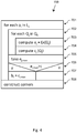
- Procedure 700 of Fig. 4 illustrates some methods implemented in the present invention.
- Loop 701 is executed for each position p i , which is in first set of reference locations L 1 510, i.e. from step 702 to 707.
- Loop 702 is executed for each subset Q j of nearest second locations Q k 514,515. Nearest second locations Q k are elements of second set of reference locations 520; they are limited either by their number or by some distance threshold.
- step 703 for each subset Q j linearity estimation e j of subset Q j is computed, by using a first computational procedure.
- step 704 for this subset Q j centre n-tuple c j 619 of subset Q j is determined.
- the centre n-tuple c j 619 of subset Q j with highest linearity estimation e j max is selected, step 705.
- the centre n-tuple c j 619 becomes non-gap element 541 and element 551 of non-gap element 541. Otherwise, centre n-tuple c j 619 becomes gap element 542.
- Fig. 5 depicts schematically a set of non-gap elements 541, of the third ordered set of reference locations 540, and gaps between them.
- a centre n-tuple - as determined by step e) - is stored as non-gap n-tuple, if the linearity estimation is above a predefined threshold.
- This predefined threshold t of non-gap n-tuples is preferably above 0.9, most preferably above 0.93. There may be implementations where the predefined threshold t is lower or higher or adaptive, depending on the area to be covered.
- the centre n-tuple (step e) is stored as gap n-tuple, if it is not a non-gap n-tuple, i.e.
- the gaps between the non-gap elements 541, particularly between special non-gap elements 546, are created by the second computational procedure by removing the gap n tuples from said third ordered set 540 of reference locations.
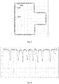
- Fig. 6 depicts an example how the linearity estimations (y-axis) of the elements of the third ordered set of reference locations 540 may be distributed.
- Reference locations 540 are ordered numerically, from 0 to about 200 (x-axis).
- Reference locations 0 to 20 have linearity estimations well above 0.95, i.e. above the predefined threshold t.
- Reference locations 31 to 51 are above 0.95 again, with an incision and a minimum below 0.7 at reference location 56, and so on.
- a line that represents the predefined threshold t is drawn at a linearity estimation of 0.93.
- centre n-tuples (according to step e) are stored as non-gap n-tuples 641, which are associated to non-gap elements 541, if the linearity estimation is above predefined threshold t. Centre n-tuples below line t are stored as gap n-tuples 642.
- Fig. 7 depicts schematically a corner element and its neighbours.
- all the elements of the third ordered set of reference locations 540 between special non-gap elements 546 have been removed from this set by second computational procedure.
- border corner location 549 is computed.
- a first linear correlation line of the non-gap n-tuples before the gap is computed; then, a second linear correlation line of the non-gap n-tuples after the gap.
- the intersection of the first linear correlation line and the second linear correlation line is constructed. This is the corner n-tuple, which substitutes the gap n-tuples of this gap.
- gap-filling elements 548 may be inserted. This has the advantage of giving nearly equidistant elements, which is quite useful for a user of the methods of this invention, because it eases the move and further computations for moveable objects 10.
- Fig. 8 depicts schematically a border 550 according to the present invention.
- Border 550 consists of a set of border locations 551, 552.
- Border 550 contains non-gap elements 541, possibly border corner locations 549, and possibly gap-filling elements 548.
Landscapes
- Engineering & Computer Science (AREA)
- Physics & Mathematics (AREA)
- General Physics & Mathematics (AREA)
- Computer Vision & Pattern Recognition (AREA)
- Theoretical Computer Science (AREA)
- Radar, Positioning & Navigation (AREA)
- Aviation & Aerospace Engineering (AREA)
- Remote Sensing (AREA)
- Automation & Control Theory (AREA)
- Management, Administration, Business Operations System, And Electronic Commerce (AREA)
- Numerical Control (AREA)
- Information Retrieval, Db Structures And Fs Structures Therefor (AREA)
- Image Analysis (AREA)
Abstract
Description
- The present invention relates to the field of determining a border, at least a part of a border. Methods like these are used to limit the activities of a technical device, for instance moveable object or a robot, to a predefined area.
- On the one hand, coming out of this area may be dangerous, illegal, or simply not desired for the moveable object. On the other hand, said moveable object should be able to cover the complete area; otherwise, machines like harvesters, mine sweepers, vacuum cleaners, and many others that use a method like this, would not be considered to work properly.
- Furthermore, the border should be recorded by automatic means; in devices of the state of the art this often contradicts to above requirements. In some cases, existing methods leave gaps in the area to be covered. In other cases, borders of the area are overrun.
- With this background, it is an object of the present invention to provide a method that improves or, at least partly, overcomes the disadvantages of the state of the art.
- These and further benefits are set out in
claim 1. Further embodiments and optional features of the present invention are set out in the dependent claims. - The present invention discloses a method for determining at least a part of the border for a moveable object in a physical area.
- The border comprises a set of border locations of the physical area. Border locations are positions in a 2-dimensional or 3-dimensional physical area. The physical border locations are associated to n-tuples of border locations.
- For determining the border, or at least a part of it, at least a first ordered set of reference locations of the physical area is used. The reference locations of the first set are associated to a set of corresponding n-tuples, wherein the set of n-tuples specifies the positions of the corresponding reference locations in the physical area.
- The reference locations are usually obtained by moving a recording device along a physical contour, which shall be defined as the physical border. During this moving, the recording device records reference locations periodically, for instance every second. Depending on the required precision of these reference locations, conditions of the terrain, precision of the recording device, etc., recording frequency may be higher or lower. Due to intrinsic imprecisions or uncertainties of the recording procedure, the reference locations recorded this way differ - at least slightly - from ideal reference locations. This may lead to imprecise definition of the borderorto unnecessary zic-zac of the border line. One strategy to cope with this would be to smoothen the border line, e.g. by using an interpolation method, like spline interpolation, of the reference locations. However, this would also smoothen edges, cornersorthe like, and thus lead awayfrom ideal reference locations. This would lead to gaps within the area to be covered.
- To avoid, at least partially, disadvantages like these, the method of the present invention performs following steps, at least:
- a) Retrieving from the storage device at least an n-tuple associated to a first reference location of the first set;
- b) Retrieving from the storage device at least a set of n-tuples associated to a plurality of second locations of the first set;
- c) Selecting from the plurality of n-tuples associated to the second locations a subset comprising nearest, in relation to the n-tuple associated to the first location, n-tuples associated to nearest second locations;
- d) Computing a linearity estimation, by using a first computational procedure, of the nearest n-tuples associated to the nearest second locations;
- e) Determining a centre n-tuple associated to a centre location of the nearest second locations and storing the centre n-tuple associated to the centre location in the storage device as a border element that is part of the border, if the linearity estimation is above a predefined threshold.
- The set of n-tuples associated to the reference locations are stored in a storage device. This makes the n-tuples - and the positions associated with them - accessible for computing systems. The storage device could be made of semiconductors, of magnetic or optic means, or other means to store and/or to handle information.
- In step a), at least an n-tuple associated to a first reference location of the first ordered set is retrieved from the storage device. The order of the first ordered set is usually given by the sequence the reference locations have been recorded by the recording device during the recording procedure.
- In step b), at least a set of n-tuples associated to a plurality of second locations of the first set is retrieved from the storage device. The number of n-tuples retrieved typically ranges between 5 and 200. The main criterion to select this plurality of second locations is their vicinity to the n-tuple associated to a first reference location, which has been retrieved in step a).
- In step c), from the plurality of n-tuples, which have been retrieved in step b), a subset is selected that comprises the nearest n-tuples, in relation to the n-tuple associated to the first location, which has been retrieved in step a).
- In step d), a linearity estimation is computed of the nearest n-tuples associated to the nearest second locations. This is done by using a first computational procedure.
- In step e), a centre n-tuple is determined associated to a centre location of the nearest second locations. If the linearity estimation, as computed in step e), is above a predefined threshold, this centre n-tuple, which is associated to the centre location, is stored in the storage device as a border element that is part of the border.
- In some embodiments, a second set of reference locations is used. The second set of reference locations may include the first ordered set of reference locations. Alternatively, the second set may consists of the first ordered set of reference locations, only. Or, the second set may as well include a plurality of additional reference locations. These additional reference locations are usually obtained by moving the recording device several times - e.g. 2 to 10 times - along a physical contour which shall be defined as the physical border.
- Based on this second set of reference locations, step b) is replaced by step b2), where from the storage device at least a set of n-tuples associated to a plurality of second locations of the second set is retrieved.
- This embodiment has the advantage of increasing the number of second locations that are used for computing the linearity estimation (step d) and determining the centre n-tuple (step e). Note that the sequence of recording and storing this second set does not play any role, because only the nearest are selected (in step c). This eases the recording procedure considerably.
- In some embodiments, the centre n-tuple is the mass centre of the nearest n-tuples or the weighted mass centre of the nearest n-tuples.
- The centre n-tuple of the nearest n-tuples can be computed in several ways. One method is to compute the mass centre of these nearest n-tuples. Another method is to attribute the nearest n-tuples with a weight. Examples for weights are: Depending on the recording device, e.g. higher weights for better recording quality; depending on the linearity estimation, e.g. higher weights for points with higher linearity or higher weights for points with linearity above a predefined threshold.
- In some embodiments, the centre n-tuple is determined by performing the steps of:
- Repeating steps c) and d) for a predefined number of subsets comprising nearest n-tuples, wherein each of said subsets has a different cardinality;
- Selecting, after step e), the centre n-tuple for the subset with highest linearity estimation, of the predefined number of subsets comprising nearest second locations.
- The number of nearest n-tuples is not constant and may vary for each n-tuple associated to a first reference location of the first set (as retrieved in step a). The number of nearest n-tuples selected may be determined by a predefined threshold of the linearity estimation, i.e. only those nearest n-tuples are selected that are above this predefined threshold. Another criterion for selecting the nearest n-tuples can be to limit their number, i.e. take a subset with n nearest n-tuples. Cardinality n of this set is between 5 and 200, preferably between 10 and 60, most preferably between 20 and 40, elements.
- Some embodiments vary the cardinality of said subsets systematically, e.g. from 20 to 40 elements, determine for each of these subsets its linearity estimation, and then (after step e), select the centre n-tuple for the subset with highest linearity estimation.
- In some embodiments, a third ordered set of reference locations, associated to a set of corresponding n-tuples, is computed, further comprising the steps of:
- Storing, after step e), the centre n-tuple associated to the centre location in the storage device as a non-gap n-tuple associated to a non-gap element that is part of the third set, if the linearity estimation is above the predefined threshold, or storing the centre n-tuple associated to the centre location in the storage device as a gap n-tuple associated to a gap element that is part of the third set, if the linearity estimation is below the predefined threshold, as part of the third ordered set of n-tuples;
- Computing a corner n-tuple associated to a corner element that is part of the border, by using a second computational procedure, wherein the second computational procedure is based on gap n-tuples and non-gap n-tuples.
- Said third ordered set of reference locations consists of gap n-tuples and non-gap n-tuples. The centre n-tuple (step e) is stored as non-gap n-tuple, if the linearity estimation is above a predefined threshold. This predefined threshold of non-gap n-tuples is preferably above 0.9, most preferably above 0.93. The centre n-tuple (step e) is stored as gap n-tuples, if it is not a non-gap n-tuple according to the definition above.
- Hence, the third ordered set of reference locations consists of centre n-tuples, as determined in step e), that are either gap n-tuples or non-gap n-tuples. This third ordered set is used to compute at least one corner n-tuple, by performing a second computational procedure. Said second computational procedure removes the gap n-tuples and substitutes this gap by determining at least one n-tuple that is between the remaining non-gap n-tuples; this n-tuple is called corner n-tuple.
- In some embodiments, the second computational procedure determines for each subset of gap n-tuples the corner n-tuple associated to the corner element, that is part of the border, by computing a first linear correlation line of the non-gap n-tuples before said subset of gap n-tuples and a second linear correlation line of the non-gap n-tuples after said subset of gap n-tuples and the corner n-tuple as the intersection of the first linear correlation line and the second linear correlation line.
- Hence, the second computational procedure first searches in the third ordered set of reference locations for a successional subset of gap n-tuples, with cardinality greater than or equal to one. Then, the procedure removes the gap n-tuples; this leads to a gap in said third ordered set. In consequence, subsets "before this gap" and a "afterthis gap" arise from this removing. These subsets maybe limited by a predefined number, e.g. 5 n-tuples subset "before this gap" and 5 n-tuples "afterthis gap" are selected. Another limitation may be to select all the n-tuples "before this gap" back to the last gap and all the n-tuples "afterthis gap" to the next gap.
- Then, a first linear correlation line of the non-gap n-tuples before the gap, i.e. before said subset of gap n-tuples, and a second linear correlation line of the non-gap n-tuples after the gap, i.e. aftersaid subset of gap n-tuples, is computed. The intersection of the first linear correlation line and the second linear correlation line is the corner n-tuple, which substitutes the gap n-tuples of this gap.
- This second computational procedure is performed for each successional subset of gap n-tuples between non-gap n-tuples.
- In some embodiments, the first computational procedure is further based on determining a centre n-tuple associated to a centre location of the nearest second locations, wherein, after computing a first line that is the linear correlation of the nearest second locations and a second line that is perpendicular on the first line, linearity estimation is result of the quotient of the squares of the distances to the first line and the squares of the distances to the second line.
- In this embodiment of the first computational procedure, which provides a linearity estimation, first the centre n-tuple is computed, based on the nearest second locations, by using one of the methods disclosed above. Then, a first line is computed that is the linear correlation of the nearest second locations. Subsequently, a second line that is perpendicular on the first line is computed. The second line crosses the first line in the centre n-tuple. By using these lines, linearity estimation is the result of the quotient of the squares of the distances to the first line and the squares of the distances to the second line.
- In some embodiments, the linearity estimation is result of an excentricity computation of the nearest n-tuples (614, 615).
- There are several methods known that perform a linearity estimation. One of these methods is disclosed e.g. in paper "Stojmenović, M.; Nayak, A.; Zunic, J.: Measuring Linearity of a Finite Set of Points. IEEE 2006".
- In some embodiments, uncertainties of the first reference locations, of the second locations, and of border elements are numerically considered.
- Uncertainties may have been produced from the recording procedure, by using the recording device, as pointed out above. For many of existing recording devices, an estimation is given for errors or uncertainties related to each of the first reference locations and/or of the second locations recorded. These uncertainties are numerically considered, e.g. by computing several border elements, e.g. one without errors, one with maximal errors in each direction, etc. After this computing, each border element is computed bytakingthe average orthe weighted average of above results.
- In some embodiments, both the first and the second set of reference locations is determined by moving the moveable object in a physical area, by determining each reference location and storing the n-tuples associated to the reference locations in the storage device. This can also be achieved by a machine that carries said recording device orthe moveable object, along a physical contour.
- For this purpose, said moveable object is equipped with an electronic control unit that is able to execute the methods described above.
- The invention will best be understood from the following detailed description of some embodiments of the invention shown in the accompanying drawings, wherein:
- Fig. 1a
- depicts schematically an area where first reference locations are obtained by a recording device along a physical contour;
- Fig. 1b
- depicts schematically an area where second reference locations are obtained by a recording device along a physical contour;
- Fig. 2
- depicts schematically border elements determined by a method according to state of the art;
- Fig. 3a
- depicts schematically a set of n-tuples with low linearity estimation;
- Fig. 3b
- depicts schematically a set of n-tuples with high linearity estimation;
- Fig. 4
- illustrates some methods implemented in the present invention;
- Fig. 5
- depicts schematically a set of non-gap elements and gaps between these non-gap elements;
- Fig. 6
- depicts schematically an example for linearity estimations and a predefined threshold;
- Fig. 7
- depicts schematically a corner element and its neighbours;
- Fig. 8
- depicts schematically a border with corner elements according to the present invention.
- In
Fig. 1a an area is shown schematically with first set ofreference locations 510, comprising a plurality of first locations 511,512. The points shown stand for reference locations in a physical area, obtained by a recording device along a physical contour. The reference locations are recorded and stored sequentially, e.g. the recording device has been moved counter-clockwise. In the example shown,reference location 512 is stored afterreference location 511. -
Fig. 1b depicts schematically an area where a set ofsecond reference locations 520 are obtained by a recording device along a physical contour, comprising a plurality ofsecond locations reference locations 510 may be a subset of the set ofsecond reference locations 520. The set ofsecond reference locations 520 is not necessarily ordered, e.g. there is no order betweensecond locations second reference locations 520 contains more elements than the first set ofreference locations 510. -
Fig. 2 depictsschematically border elements 551 determined by a method according to state of the art. The plurality offirst locations border elements 551 andborder corner location 549 are shown as big dots. It is clearly visible that smoothening the plurality offirst locations 511 leads, as a result, to a set ofborder locations 551 that avoids zic-zac of the border line. However, the set ofborder locations 551 does not includeborder corner location 549. -
Fig. 3a and 3b give an idea of the meaning of a linearity estimation: The plurality offirst locations Fig. 3a lies within a "quite round" ellipse. Hence, this set offirst locations first locations Fig. 3b lies within a "quite longish" ellipse, where the y-extension of this ellipse is significantly longer than its x-extension. As a result, this set offirst locations -
Procedure 700 ofFig. 4 illustrates some methods implemented in the present invention.Loop 701 is executed for each position pi, which is in first set ofreference locations L 1 510, i.e. fromstep 702 to 707.Loop 702 is executed for each subset Qj of nearest second locations Qk 514,515. Nearest second locations Qk are elements of second set ofreference locations 520; they are limited either by their number or by some distance threshold. Instep 703, for each subset Qj linearity estimation ej of subset Qj is computed, by using a first computational procedure. Instep 704, for this subset Qj centre n-tuple cj 619 of subset Qj is determined. - After having computed the linearity estimation of at least 2, preferably between 20 and 40, subsets, the centre n-tuple cj 619 of subset Qj with highest linearity estimation ej max is selected,
step 705. In cases when highest linearity estimation ej max is above a predefined threshold t, as determined instep 706, the centre n-tuple cj 619 becomesnon-gap element 541 andelement 551 ofnon-gap element 541. Otherwise, centre n-tuple cj 619 becomesgap element 542. - After having determined all
non-gap elements 541 andgap elements 542, corners are constructed according to the second computational procedure,step 708. -
Fig. 5 depicts schematically a set ofnon-gap elements 541, of the third ordered set of reference locations 540, and gaps between them. A centre n-tuple - as determined by step e) - is stored as non-gap n-tuple, if the linearity estimation is above a predefined threshold. This predefined threshold t of non-gap n-tuples is preferably above 0.9, most preferably above 0.93. There may be implementations where the predefined threshold t is lower or higher or adaptive, depending on the area to be covered. The centre n-tuple (step e) is stored as gap n-tuple, if it is not a non-gap n-tuple, i.e. when its linearity estimation is below the predefined threshold t. The gaps between thenon-gap elements 541, particularly between specialnon-gap elements 546, are created by the second computational procedure by removing the gap n tuples from said third ordered set 540 of reference locations. -
Fig. 6 depicts an example how the linearity estimations (y-axis) of the elements of the third ordered set of reference locations 540 may be distributed. Reference locations 540 are ordered numerically, from 0 to about 200 (x-axis). Reference locations 0 to 20 have linearity estimations well above 0.95, i.e. above the predefined threshold t. Between reference locations 21 to 30 there is an incision, with a minimum below 0.7 at reference locations 25 and 26. Reference locations 31 to 51 are above 0.95 again, with an incision and a minimum below 0.7 at reference location 56, and so on. A line that represents the predefined threshold t is drawn at a linearity estimation of 0.93. Consequently, centre n-tuples (according to step e) are stored as non-gap n-tuples 641, which are associated tonon-gap elements 541, if the linearity estimation is above predefined threshold t. Centre n-tuples below line t are stored as gap n-tuples 642. -
Fig. 7 depicts schematically a corner element and its neighbours. As elaborated above, all the elements of the third ordered set of reference locations 540 between specialnon-gap elements 546 have been removed from this set by second computational procedure. Then,border corner location 549 is computed. Forthis, a first linear correlation line of the non-gap n-tuples before the gap is computed; then, a second linear correlation line of the non-gap n-tuples after the gap. In the next step, the intersection of the first linear correlation line and the second linear correlation line is constructed. This is the corner n-tuple, which substitutes the gap n-tuples of this gap. Betweenborder corner location 549 and specialnon-gap elements 546 some gap-fillingelements 548 may be inserted. This has the advantage of giving nearly equidistant elements, which is quite useful for a user of the methods of this invention, because it eases the move and further computations for moveable objects 10. -
Fig. 8 depicts schematically aborder 550 according to the present invention.Border 550 consists of a set ofborder locations 551, 552.Border 550 containsnon-gap elements 541, possibly bordercorner locations 549, and possibly gap-fillingelements 548. -
- 10
- moveable object
- 20
- electronic control unit, ECU
- 300
- storage device
- 510
- first set of reference locations
- 511
- first location (511) of the first set (510)
- 511.. 515
- plurality of first locations
- 514,515
- nearest first locations
- 519
- centre location
- 520
- second set of reference locations
- 540
- third set of reference locations (gap locations)
- 541
- non-gap element
- 542
- gap element
- 546
- special non-gap element
- 548
- gap-filling elements
- 549
- border corner location
- 550
- non-gap element
- 551,552
- set of border locations
- 610
- first set of n-tuples of reference locations
- 611
- n-tuple (coordinate) of first reference location
- 611.. 615
- plurality of n-tuples of first locations
- 614,615
- n-tuples of nearest first locations
- 619
- n-tuple of centre location
- 620
- second set of n-tuples of reference locations
- 640
- third set of n-tuples (gap n-tuples)
- 641
- non-gap n-tuple
- 642
- gap n-tuple
- 649
- n-tuple of border corner location
- 650
- n-tuples of border
- 651,652
- set of n-tuples of border locations
- 700, 710 to 780
- procedure, steps of
procedure 700 - cj
- centre of subset Qj
- ej
- excentricity of subset Qj
- L1
- first set of reference locations
- pi
- position, in first set of reference locations
- Qj
- subset of nearest second locations
- Qk
- nearest second locations
- t
- predefined threshold
Claims (12)
- Method for determining at least a part of the border (550) for a moveable object (10) in a physical area by using at least a first ordered set (510) of reference locations of the physical area,
wherein the border (550) comprises a set of border locations (551, 552) of the physical area, wherein the reference locations of the first set (510) are associated to a set of corresponding n-tuples (610), wherein the set of n-tuples (610) specifies the positions of the corresponding reference locations (510) in the physical area,
wherein the set of n-tuples (610) associated to the reference locations of the first and of the second set (510) are stored in a storage device (300),
said method comprising at least the steps of:a) retrieving from the storage device (300) at least an n-tuple (611) associated to a first reference location (511) of the first set (510);b) retrieving from the storage device (300) at least a set of n-tuples (612, 613) associated to a plurality of second locations (512,513) of the first set (510);c) selecting from the plurality of n-tuples (612, 613) associated to the second locations (512, 513) a subset comprising nearest, in relation to the n-tuple (611) associated to the first location (511), n-tuples (614,615) associated to nearest second locations (514, 515);d) computing a linearity estimation, by using a first computational procedure, of the nearest n-tuples (614, 615) associated to the nearest second locations (514,515);e) determining a centre n-tuple (619) associated to a centre location (519) of the nearest second locations (525, 526) and
storing the centre n-tuple (619) associated to the centre location (519) in the storage device (300) as a border element (551) that is part of the border (550), if the linearity estimation is above a predefined threshold. - Method according to claim 1,
using a second set (520) of reference locations, that may include the first ordered set (510) of reference locations, replacing step b) by step b2), wherein
b2) retrieving from the storage device (300) at least a set of n-tuples (612, 613) associated to a plurality of second locations (512,513) of the second set (520). - Method according to claim 1 or 2,
wherein the centre n-tuple (619) is the mass centre of the nearest n-tuples (614, 615) orthe weighted mass centre of the nearest n-tuples (614, 615). - Method according to claim 1,2, or 3, further comprising the steps of:- repeating steps c) and d) for a predefined number of subsets comprising nearest n-tuples (614,615), wherein each of said subsets has a different cardinality;- selecting, after step e), the centre n-tuple (619) for the subset with highest linearity estimation, of the predefined number of subsets comprising nearest second locations (514, 515).
- Method according to claim 4,
wherein the cardinality of subsets comprising nearest n-tuples (625, 614, 615) is between 5 and 200, preferably between 10 and 60, most preferably between 20 and 40, elements. - Method according to one of the preceding claims, using a third ordered set of reference locations (540), associated to a set of corresponding n-tuples (640), further comprising the steps of:- storing, after step e), the centre n-tuple (619) associated to the centre location (519) in the storage device (300) as a non-gap n-tuple (641) associated to a non-gap element (541) that is part of the third set (540), if the linearity estimation is above the predefined threshold, or storing the centre n-tuple (619) associated to the centre location (519) in the storage device (300) as a gap n-tuple (642) associated to a gap element (542) that is part of the third set (540), if the linearity estimation is below the predefined threshold, as part of the third ordered set of n-tuples (640);- computing a corner n-tuple (649) associated to a corner element (549) that is part of the border (550), by using a second computational procedure, wherein the second computational procedure is based on gap n-tuples (642) and non-gap n-tuples (641).
- Method according to claim 6,
by using the subset of non-gap n-tuples (641) and gap n-tuples (642) that are part of the third ordered set of reference locations (540),
wherein the second computational procedure determines for each subset of gap n-tuples (642) the corner n-tuple (649) associated to the corner element (549), that is part of the border (550),
by computing a first linear correlation line of the non-gap n-tuples (641) before said subset of gap n-tuples (642) and a second linear correlation line of the non-gap n-tuples (641) after said subset of gap n-tuples (642) and the corner n-tuple (649) as the intersection of the first linear correlation line and the second linear correlation line. - Method according to one of the preceding claims,
wherein the first computational procedure is further based on determining a centre n-tuple (619) associated to a centre location (519) of the nearest second locations (514,515),
wherein, after computing a first line that is the linear correlation of the nearest second locations (514, 515) and a second line that is perpendicular on the first line, linearity estimation is result of the quotient of the squares of the distances to the first line and the squares of the distances to the second line. - Method according to one of the preceding claims,
wherein the linearity estimation is result of an excentricity computation of the nearest n-tuples (614,615). - Method according to one of the preceding claims,
wherein uncertainties of the first reference locations (511), of the second locations (521, 522), and of border elements (551) are numerically considered. - Method according to one of the preceding claims,
wherein both the first and the second set (510,520) of reference locations (511, 521, 522) is determined by moving the moveable object (10) in a physical area, by determining each reference location (511,521,522) and storing the n-tuples (611, 621, 622) associated to the reference locations (511,521,522) in the storage device (300). - Moveable object (10) with an electronic control unit (20) that is able to execute the method according to claim 1 to 11.
Priority Applications (1)
| Application Number | Priority Date | Filing Date | Title |
|---|---|---|---|
| PL17198571T PL3316066T3 (en) | 2016-10-26 | 2017-10-26 | Method for determining at least a part of a border |
Applications Claiming Priority (1)
| Application Number | Priority Date | Filing Date | Title |
|---|---|---|---|
| DE102016120461 | 2016-10-26 |
Publications (2)
| Publication Number | Publication Date |
|---|---|
| EP3316066A1 true EP3316066A1 (en) | 2018-05-02 |
| EP3316066B1 EP3316066B1 (en) | 2019-09-25 |
Family
ID=60201837
Family Applications (1)
| Application Number | Title | Priority Date | Filing Date |
|---|---|---|---|
| EP17198571.6A Active EP3316066B1 (en) | 2016-10-26 | 2017-10-26 | Method for determining at least a part of a border |
Country Status (4)
| Country | Link |
|---|---|
| EP (1) | EP3316066B1 (en) |
| CN (1) | CN107993240B (en) |
| ES (1) | ES2763166T3 (en) |
| PL (1) | PL3316066T3 (en) |
Cited By (1)
| Publication number | Priority date | Publication date | Assignee | Title |
|---|---|---|---|---|
| GB2618104A (en) * | 2022-04-27 | 2023-11-01 | Dyson Technology Ltd | Method for edge cleaning |
Citations (2)
| Publication number | Priority date | Publication date | Assignee | Title |
|---|---|---|---|---|
| US20100076599A1 (en) * | 2008-09-20 | 2010-03-25 | Steven Jacobs | Manually driven determination of a region of interest (roi) or a path of interest (poi) for a robotic device |
| US20120265391A1 (en) * | 2009-06-18 | 2012-10-18 | Michael Todd Letsky | Method for establishing a desired area of confinement for an autonomous robot and autonomous robot implementing a control system for executing the same |
Family Cites Families (2)
| Publication number | Priority date | Publication date | Assignee | Title |
|---|---|---|---|---|
| US7275058B2 (en) * | 2003-02-18 | 2007-09-25 | Seiko Epson Corporation | Method and system for finding a k order statistic in a union of sorted sets |
| DE102007053008A1 (en) * | 2007-11-05 | 2009-05-14 | Repetzki, Sebastian, Dr.-Ing. | Target body and method for determining its spatial position |
-
2017
- 2017-10-26 CN CN201711012616.0A patent/CN107993240B/en active Active
- 2017-10-26 ES ES17198571T patent/ES2763166T3/en active Active
- 2017-10-26 EP EP17198571.6A patent/EP3316066B1/en active Active
- 2017-10-26 PL PL17198571T patent/PL3316066T3/en unknown
Patent Citations (2)
| Publication number | Priority date | Publication date | Assignee | Title |
|---|---|---|---|---|
| US20100076599A1 (en) * | 2008-09-20 | 2010-03-25 | Steven Jacobs | Manually driven determination of a region of interest (roi) or a path of interest (poi) for a robotic device |
| US20120265391A1 (en) * | 2009-06-18 | 2012-10-18 | Michael Todd Letsky | Method for establishing a desired area of confinement for an autonomous robot and autonomous robot implementing a control system for executing the same |
Non-Patent Citations (2)
| Title |
|---|
| MILOS STOJMENOVIC ET AL: "Measuring Linearity of a Finite Set of Points", CYBERNETICS AND INTELLIGENT SYSTEMS, 2006 IEEE CONFERENCE ON, IEEE, PISCATAWAY, NJ, USA, 1 June 2006 (2006-06-01), pages 1 - 6, XP031020046, ISBN: 978-1-4244-0023-2 * |
| STOJMENOVIC, M.; NAYAK, A.; ZUNIC, J.: "Measuring Linearity of a Finite Set of Points", 2006, IEEE |
Cited By (2)
| Publication number | Priority date | Publication date | Assignee | Title |
|---|---|---|---|---|
| GB2618104A (en) * | 2022-04-27 | 2023-11-01 | Dyson Technology Ltd | Method for edge cleaning |
| GB2618104B (en) * | 2022-04-27 | 2024-10-30 | Dyson Technology Ltd | Method for edge cleaning |
Also Published As
| Publication number | Publication date |
|---|---|
| CN107993240B (en) | 2023-08-04 |
| CN107993240A (en) | 2018-05-04 |
| PL3316066T3 (en) | 2020-04-30 |
| EP3316066B1 (en) | 2019-09-25 |
| ES2763166T3 (en) | 2020-05-27 |
Similar Documents
| Publication | Publication Date | Title |
|---|---|---|
| JP6800989B2 (en) | Robot routing systems, methods, robots and media | |
| Davison | Real-time simultaneous localisation and mapping with a single camera | |
| CN109665328A (en) | A kind of dynamic optimization chest palletizing method, information data processing terminal | |
| KR100918706B1 (en) | Apparatus and Method of Estimating Camera Position | |
| JP2018538599A (en) | Method and apparatus for grouping web page labels in a web browser | |
| CN107135482B (en) | Update the method and device of fingerprint base | |
| CN108961294A (en) | A kind of dividing method and device of three-dimensional point cloud | |
| EP3316066B1 (en) | Method for determining at least a part of a border | |
| WO2024140553A1 (en) | Travel path planning method and apparatus, self-moving robot, and storage medium | |
| CN112948372B (en) | A method and system for index-based fixed-track length seismic data retrieval | |
| US12001212B2 (en) | Path planning method and device for unmanned device | |
| CN107261500A (en) | A kind of method, device and mobile terminal for positioning object | |
| KR102695353B1 (en) | Method for robot path finding | |
| CN105589896B (en) | Data mining method and device | |
| CN113888608A (en) | Target tracking method, device, equipment and medium | |
| US20130238985A1 (en) | Methods and devices for eliminating cracks within pages | |
| CN118918244A (en) | Building three-dimensional reconstruction method and system based on point cloud | |
| KR102076988B1 (en) | Apparatus for indoor location measurement using beacon placed indoor and operating method thereof | |
| KR102007378B1 (en) | Apparatus for optimizing beacon arrangement and operating method thereof | |
| CN112308476A (en) | Order form combining method, device and storage medium | |
| KR100863228B1 (en) | Approximate Indexing Method for Road Network Databases | |
| CN106997355B (en) | Method and device for obtaining distance and determining the shortest line segment based on Mongodb | |
| CN113752252A (en) | Linkage method and system for water constraint layer and laser impact track of impeller | |
| CN116028787A (en) | Data processing method and device, device, storage medium | |
| CN112241975A (en) | Matching and positioning method and matching positioning device of feature template |
Legal Events
| Date | Code | Title | Description |
|---|---|---|---|
| PUAI | Public reference made under article 153(3) epc to a published international application that has entered the european phase |
Free format text: ORIGINAL CODE: 0009012 |
|
| STAA | Information on the status of an ep patent application or granted ep patent |
Free format text: STATUS: THE APPLICATION HAS BEEN PUBLISHED |
|
| AK | Designated contracting states |
Kind code of ref document: A1 Designated state(s): AL AT BE BG CH CY CZ DE DK EE ES FI FR GB GR HR HU IE IS IT LI LT LU LV MC MK MT NL NO PL PT RO RS SE SI SK SM TR |
|
| AX | Request for extension of the european patent |
Extension state: BA ME |
|
| STAA | Information on the status of an ep patent application or granted ep patent |
Free format text: STATUS: REQUEST FOR EXAMINATION WAS MADE |
|
| 17P | Request for examination filed |
Effective date: 20181031 |
|
| RBV | Designated contracting states (corrected) |
Designated state(s): AL AT BE BG CH CY CZ DE DK EE ES FI FR GB GR HR HU IE IS IT LI LT LU LV MC MK MT NL NO PL PT RO RS SE SI SK SM TR |
|
| STAA | Information on the status of an ep patent application or granted ep patent |
Free format text: STATUS: EXAMINATION IS IN PROGRESS |
|
| 17Q | First examination report despatched |
Effective date: 20190103 |
|
| GRAP | Despatch of communication of intention to grant a patent |
Free format text: ORIGINAL CODE: EPIDOSNIGR1 |
|
| STAA | Information on the status of an ep patent application or granted ep patent |
Free format text: STATUS: GRANT OF PATENT IS INTENDED |
|
| INTG | Intention to grant announced |
Effective date: 20190502 |
|
| GRAS | Grant fee paid |
Free format text: ORIGINAL CODE: EPIDOSNIGR3 |
|
| GRAA | (expected) grant |
Free format text: ORIGINAL CODE: 0009210 |
|
| STAA | Information on the status of an ep patent application or granted ep patent |
Free format text: STATUS: THE PATENT HAS BEEN GRANTED |
|
| AK | Designated contracting states |
Kind code of ref document: B1 Designated state(s): AL AT BE BG CH CY CZ DE DK EE ES FI FR GB GR HR HU IE IS IT LI LT LU LV MC MK MT NL NO PL PT RO RS SE SI SK SM TR |
|
| REG | Reference to a national code |
Ref country code: GB Ref legal event code: FG4D |
|
| REG | Reference to a national code |
Ref country code: CH Ref legal event code: EP |
|
| REG | Reference to a national code |
Ref country code: AT Ref legal event code: REF Ref document number: 1184434 Country of ref document: AT Kind code of ref document: T Effective date: 20191015 |
|
| REG | Reference to a national code |
Ref country code: IE Ref legal event code: FG4D |
|
| REG | Reference to a national code |
Ref country code: DE Ref legal event code: R096 Ref document number: 602017007289 Country of ref document: DE |
|
| REG | Reference to a national code |
Ref country code: NL Ref legal event code: MP Effective date: 20190925 |
|
| PG25 | Lapsed in a contracting state [announced via postgrant information from national office to epo] |
Ref country code: FI Free format text: LAPSE BECAUSE OF FAILURE TO SUBMIT A TRANSLATION OF THE DESCRIPTION OR TO PAY THE FEE WITHIN THE PRESCRIBED TIME-LIMIT Effective date: 20190925 Ref country code: HR Free format text: LAPSE BECAUSE OF FAILURE TO SUBMIT A TRANSLATION OF THE DESCRIPTION OR TO PAY THE FEE WITHIN THE PRESCRIBED TIME-LIMIT Effective date: 20190925 Ref country code: SE Free format text: LAPSE BECAUSE OF FAILURE TO SUBMIT A TRANSLATION OF THE DESCRIPTION OR TO PAY THE FEE WITHIN THE PRESCRIBED TIME-LIMIT Effective date: 20190925 Ref country code: NO Free format text: LAPSE BECAUSE OF FAILURE TO SUBMIT A TRANSLATION OF THE DESCRIPTION OR TO PAY THE FEE WITHIN THE PRESCRIBED TIME-LIMIT Effective date: 20191225 Ref country code: LT Free format text: LAPSE BECAUSE OF FAILURE TO SUBMIT A TRANSLATION OF THE DESCRIPTION OR TO PAY THE FEE WITHIN THE PRESCRIBED TIME-LIMIT Effective date: 20190925 Ref country code: BG Free format text: LAPSE BECAUSE OF FAILURE TO SUBMIT A TRANSLATION OF THE DESCRIPTION OR TO PAY THE FEE WITHIN THE PRESCRIBED TIME-LIMIT Effective date: 20191225 |
|
| REG | Reference to a national code |
Ref country code: LT Ref legal event code: MG4D |
|
| PG25 | Lapsed in a contracting state [announced via postgrant information from national office to epo] |
Ref country code: RS Free format text: LAPSE BECAUSE OF FAILURE TO SUBMIT A TRANSLATION OF THE DESCRIPTION OR TO PAY THE FEE WITHIN THE PRESCRIBED TIME-LIMIT Effective date: 20190925 Ref country code: LV Free format text: LAPSE BECAUSE OF FAILURE TO SUBMIT A TRANSLATION OF THE DESCRIPTION OR TO PAY THE FEE WITHIN THE PRESCRIBED TIME-LIMIT Effective date: 20190925 Ref country code: GR Free format text: LAPSE BECAUSE OF FAILURE TO SUBMIT A TRANSLATION OF THE DESCRIPTION OR TO PAY THE FEE WITHIN THE PRESCRIBED TIME-LIMIT Effective date: 20191226 |
|
| REG | Reference to a national code |
Ref country code: CH Ref legal event code: NV Representative=s name: VALIPAT S.A. C/O BOVARD SA NEUCHATEL, CH |
|
| PG25 | Lapsed in a contracting state [announced via postgrant information from national office to epo] |
Ref country code: EE Free format text: LAPSE BECAUSE OF FAILURE TO SUBMIT A TRANSLATION OF THE DESCRIPTION OR TO PAY THE FEE WITHIN THE PRESCRIBED TIME-LIMIT Effective date: 20190925 Ref country code: NL Free format text: LAPSE BECAUSE OF FAILURE TO SUBMIT A TRANSLATION OF THE DESCRIPTION OR TO PAY THE FEE WITHIN THE PRESCRIBED TIME-LIMIT Effective date: 20190925 Ref country code: PT Free format text: LAPSE BECAUSE OF FAILURE TO SUBMIT A TRANSLATION OF THE DESCRIPTION OR TO PAY THE FEE WITHIN THE PRESCRIBED TIME-LIMIT Effective date: 20200127 Ref country code: AL Free format text: LAPSE BECAUSE OF FAILURE TO SUBMIT A TRANSLATION OF THE DESCRIPTION OR TO PAY THE FEE WITHIN THE PRESCRIBED TIME-LIMIT Effective date: 20190925 Ref country code: RO Free format text: LAPSE BECAUSE OF FAILURE TO SUBMIT A TRANSLATION OF THE DESCRIPTION OR TO PAY THE FEE WITHIN THE PRESCRIBED TIME-LIMIT Effective date: 20190925 |
|
| REG | Reference to a national code |
Ref country code: ES Ref legal event code: FG2A Ref document number: 2763166 Country of ref document: ES Kind code of ref document: T3 Effective date: 20200527 |
|
| PG25 | Lapsed in a contracting state [announced via postgrant information from national office to epo] |
Ref country code: CZ Free format text: LAPSE BECAUSE OF FAILURE TO SUBMIT A TRANSLATION OF THE DESCRIPTION OR TO PAY THE FEE WITHIN THE PRESCRIBED TIME-LIMIT Effective date: 20190925 Ref country code: SM Free format text: LAPSE BECAUSE OF FAILURE TO SUBMIT A TRANSLATION OF THE DESCRIPTION OR TO PAY THE FEE WITHIN THE PRESCRIBED TIME-LIMIT Effective date: 20190925 Ref country code: SK Free format text: LAPSE BECAUSE OF FAILURE TO SUBMIT A TRANSLATION OF THE DESCRIPTION OR TO PAY THE FEE WITHIN THE PRESCRIBED TIME-LIMIT Effective date: 20190925 Ref country code: IS Free format text: LAPSE BECAUSE OF FAILURE TO SUBMIT A TRANSLATION OF THE DESCRIPTION OR TO PAY THE FEE WITHIN THE PRESCRIBED TIME-LIMIT Effective date: 20200224 |
|
| REG | Reference to a national code |
Ref country code: DE Ref legal event code: R097 Ref document number: 602017007289 Country of ref document: DE |
|
| PG2D | Information on lapse in contracting state deleted |
Ref country code: IS |
|
| PG25 | Lapsed in a contracting state [announced via postgrant information from national office to epo] |
Ref country code: LU Free format text: LAPSE BECAUSE OF NON-PAYMENT OF DUE FEES Effective date: 20191026 Ref country code: DK Free format text: LAPSE BECAUSE OF FAILURE TO SUBMIT A TRANSLATION OF THE DESCRIPTION OR TO PAY THE FEE WITHIN THE PRESCRIBED TIME-LIMIT Effective date: 20190925 Ref country code: IS Free format text: LAPSE BECAUSE OF FAILURE TO SUBMIT A TRANSLATION OF THE DESCRIPTION OR TO PAY THE FEE WITHIN THE PRESCRIBED TIME-LIMIT Effective date: 20200126 |
|
| PLBE | No opposition filed within time limit |
Free format text: ORIGINAL CODE: 0009261 |
|
| STAA | Information on the status of an ep patent application or granted ep patent |
Free format text: STATUS: NO OPPOSITION FILED WITHIN TIME LIMIT |
|
| REG | Reference to a national code |
Ref country code: BE Ref legal event code: MM Effective date: 20191031 |
|
| PG25 | Lapsed in a contracting state [announced via postgrant information from national office to epo] |
Ref country code: MC Free format text: LAPSE BECAUSE OF FAILURE TO SUBMIT A TRANSLATION OF THE DESCRIPTION OR TO PAY THE FEE WITHIN THE PRESCRIBED TIME-LIMIT Effective date: 20190925 Ref country code: BE Free format text: LAPSE BECAUSE OF NON-PAYMENT OF DUE FEES Effective date: 20191031 |
|
| 26N | No opposition filed |
Effective date: 20200626 |
|
| PG25 | Lapsed in a contracting state [announced via postgrant information from national office to epo] |
Ref country code: IE Free format text: LAPSE BECAUSE OF NON-PAYMENT OF DUE FEES Effective date: 20191026 |
|
| PG25 | Lapsed in a contracting state [announced via postgrant information from national office to epo] |
Ref country code: SI Free format text: LAPSE BECAUSE OF FAILURE TO SUBMIT A TRANSLATION OF THE DESCRIPTION OR TO PAY THE FEE WITHIN THE PRESCRIBED TIME-LIMIT Effective date: 20190925 |
|
| PG25 | Lapsed in a contracting state [announced via postgrant information from national office to epo] |
Ref country code: CY Free format text: LAPSE BECAUSE OF FAILURE TO SUBMIT A TRANSLATION OF THE DESCRIPTION OR TO PAY THE FEE WITHIN THE PRESCRIBED TIME-LIMIT Effective date: 20190925 |
|
| PG25 | Lapsed in a contracting state [announced via postgrant information from national office to epo] |
Ref country code: HU Free format text: LAPSE BECAUSE OF FAILURE TO SUBMIT A TRANSLATION OF THE DESCRIPTION OR TO PAY THE FEE WITHIN THE PRESCRIBED TIME-LIMIT; INVALID AB INITIO Effective date: 20171026 Ref country code: MT Free format text: LAPSE BECAUSE OF FAILURE TO SUBMIT A TRANSLATION OF THE DESCRIPTION OR TO PAY THE FEE WITHIN THE PRESCRIBED TIME-LIMIT Effective date: 20190925 |
|
| REG | Reference to a national code |
Ref country code: AT Ref legal event code: UEP Ref document number: 1184434 Country of ref document: AT Kind code of ref document: T Effective date: 20190925 |
|
| PG25 | Lapsed in a contracting state [announced via postgrant information from national office to epo] |
Ref country code: TR Free format text: LAPSE BECAUSE OF FAILURE TO SUBMIT A TRANSLATION OF THE DESCRIPTION OR TO PAY THE FEE WITHIN THE PRESCRIBED TIME-LIMIT Effective date: 20190925 |
|
| PG25 | Lapsed in a contracting state [announced via postgrant information from national office to epo] |
Ref country code: MK Free format text: LAPSE BECAUSE OF FAILURE TO SUBMIT A TRANSLATION OF THE DESCRIPTION OR TO PAY THE FEE WITHIN THE PRESCRIBED TIME-LIMIT Effective date: 20190925 |
|
| REG | Reference to a national code |
Ref country code: DE Ref legal event code: R079 Ref document number: 602017007289 Country of ref document: DE Free format text: PREVIOUS MAIN CLASS: G05D0001020000 Ipc: G05D0001430000 |
|
| PGFP | Annual fee paid to national office [announced via postgrant information from national office to epo] |
Ref country code: GB Payment date: 20231025 Year of fee payment: 7 |
|
| PGFP | Annual fee paid to national office [announced via postgrant information from national office to epo] |
Ref country code: ES Payment date: 20231117 Year of fee payment: 7 |
|
| PGFP | Annual fee paid to national office [announced via postgrant information from national office to epo] |
Ref country code: CH Payment date: 20231101 Year of fee payment: 7 |
|
| PGFP | Annual fee paid to national office [announced via postgrant information from national office to epo] |
Ref country code: PL Payment date: 20231017 Year of fee payment: 7 |
|
| REG | Reference to a national code |
Ref country code: CH Ref legal event code: PL |
|
| GBPC | Gb: european patent ceased through non-payment of renewal fee |
Effective date: 20241026 |
|
| PG25 | Lapsed in a contracting state [announced via postgrant information from national office to epo] |
Ref country code: GB Free format text: LAPSE BECAUSE OF NON-PAYMENT OF DUE FEES Effective date: 20241026 |
|
| PG25 | Lapsed in a contracting state [announced via postgrant information from national office to epo] |
Ref country code: CH Free format text: LAPSE BECAUSE OF NON-PAYMENT OF DUE FEES Effective date: 20241031 |
|
| REG | Reference to a national code |
Ref country code: ES Ref legal event code: FD2A Effective date: 20251203 |
|
| PGFP | Annual fee paid to national office [announced via postgrant information from national office to epo] |
Ref country code: DE Payment date: 20251020 Year of fee payment: 9 |
|
| PGFP | Annual fee paid to national office [announced via postgrant information from national office to epo] |
Ref country code: AT Payment date: 20251021 Year of fee payment: 9 |
|
| PGFP | Annual fee paid to national office [announced via postgrant information from national office to epo] |
Ref country code: IT Payment date: 20251031 Year of fee payment: 9 |
|
| PGFP | Annual fee paid to national office [announced via postgrant information from national office to epo] |
Ref country code: FR Payment date: 20251022 Year of fee payment: 9 |
|
| PG25 | Lapsed in a contracting state [announced via postgrant information from national office to epo] |
Ref country code: ES Free format text: LAPSE BECAUSE OF NON-PAYMENT OF DUE FEES Effective date: 20241027 |