EP3316065A1 - Method for determining a path - Google Patents
Method for determining a path Download PDFInfo
- Publication number
- EP3316065A1 EP3316065A1 EP17198570.8A EP17198570A EP3316065A1 EP 3316065 A1 EP3316065 A1 EP 3316065A1 EP 17198570 A EP17198570 A EP 17198570A EP 3316065 A1 EP3316065 A1 EP 3316065A1
- Authority
- EP
- European Patent Office
- Prior art keywords
- contour
- location
- tuples
- reference location
- locations
- Prior art date
- Legal status (The legal status is an assumption and is not a legal conclusion. Google has not performed a legal analysis and makes no representation as to the accuracy of the status listed.)
- Granted
Links
Images



Classifications
-
- G—PHYSICS
- G05—CONTROLLING; REGULATING
- G05D—SYSTEMS FOR CONTROLLING OR REGULATING NON-ELECTRIC VARIABLES
- G05D1/00—Control of position, course, altitude or attitude of land, water, air or space vehicles, e.g. using automatic pilots
- G05D1/02—Control of position or course in two dimensions
- G05D1/021—Control of position or course in two dimensions specially adapted to land vehicles
- G05D1/0212—Control of position or course in two dimensions specially adapted to land vehicles with means for defining a desired trajectory
- G05D1/0219—Control of position or course in two dimensions specially adapted to land vehicles with means for defining a desired trajectory ensuring the processing of the whole working surface
-
- G—PHYSICS
- G01—MEASURING; TESTING
- G01C—MEASURING DISTANCES, LEVELS OR BEARINGS; SURVEYING; NAVIGATION; GYROSCOPIC INSTRUMENTS; PHOTOGRAMMETRY OR VIDEOGRAMMETRY
- G01C21/00—Navigation; Navigational instruments not provided for in groups G01C1/00 - G01C19/00
- G01C21/26—Navigation; Navigational instruments not provided for in groups G01C1/00 - G01C19/00 specially adapted for navigation in a road network
- G01C21/34—Route searching; Route guidance
- G01C21/3407—Route searching; Route guidance specially adapted for specific applications
Definitions
- the present invention relates to the field of determining a path for a moveable object in a physical area.
- Said moveable object may be an aviation device, e.g. an autonomous aviation device, a moveable robot, e.g. for service purposes, for dangerous tasks like mine sweeping, or for agricultural uses like seeding or mowing, or a ship or submarine, e.g. to search through some area, or a similar device.
- the notion "robot” means the same as "moveable object”.
- the present invention discloses a method for determining a path where a moveable object - as defined above - should move on.
- a path consists of an ordered set of positions in a physical area the moveable object or robot can move to.
- the robot moves from one position to another position, according to the order of the ordered set.
- the method of this invention determines each of these positions.
- a position determined by this method is called target location.
- the method is based on at least a first and a second reference location. These - and, if necessary, further - reference locations are a set of positions in a physical area. They are associated to a set of corresponding n-tuples.
- the reference locations are assumed to be something given. To determine these reference locations may be object of a different invention. However, these inventions do not rely on each other.
- orientation information is used to determine the path for the robot.
- the orientation information can be a preferred angle or angle range where the next position should be located. It can - additionally or alternatively - be a direction or preferred direction, an information like "go preferably left” or “go preferably clockwise” or the like.
- the orientation information can also be a prevention, e.g. "do not go into this orthat direction”.
- the reference locations are comprised in a first contour.
- a contour consists of a set of reference locations.
- the contour may be understood as a kind of border the robot should move within. However, in some situations the robot may be allowed to cross the contour.
- n-tuples may be a set of coordinates, e.g. of the form ⁇ x i , y i , o i > for robots that move in a 2-dimensional area, where x i and y i represent x- and y-coordinates of the positions of the corresponding locations, and o i represents orientation information.
- the n-tuples may contain other or additional information, for example: For robots that move in a 3-dimensional area, z-coordinates are used in addition.
- the coordinates may be represented as polar coordinates or in another coordinate system.
- the coordinates may as well be represented as functions. Information on uncertainties (e.g. measurement uncertainties) may also be contained in the n-tuples.
- the set of n-tuples of the first and the second reference location are stored in a storage device. This makes the n-tuples - and the positions associated with them - accessible for computing systems.
- the storage device could be made of semiconductors, of magnetic or optic means, or other means to store and/orto handle information.
- the method according to the present invention comprises at least the steps of:
- the storage device is both used to retrieve the set of n-tuples associated to the first and the second reference location and to store the n-tuple associated to the first target location in the storage device, which is result of a first computational procedure.
- the first computational procedure uses at least information that is related to the position of the first and the second reference location and the orientation information.
- Executing this method repeatedly leads to a second contour that lies essentially within the first contour. Therefore, the robot first follows the set of first target locations, comes back to a - basically arbitrary - starting point. After this first round, the robot takes the second contour and transforms it into a new first contour, determines a next set of first target locations, follows this, and so on. By using this method, the robot moves essentially in always-narrower rounds.
- the orientation information may be, for instance: Move clockwise or counter-clockwise; keep a predefined position - e.g. the centre of an area - right or left; move up or down; decide true or false.
- This information is used in the first computational procedure, typically when the computation leads to more than one, particularly to two, first target locations. Then, the orientation information of Boolean type is of relevance to decide which one of these first target locations to take.
- the n-tuple comprises at least the orientation information and at least one x-coordinate and one y-coordinate and/or a function that represents at least a part of the first contour.
- the n-tuples which are associated to corresponding physical positions, may be of the form ⁇ x i , y i , o i >, where x i and y i represent x- and y-coordinates of the positions of the corresponding locations, respectively, and o i represents orientation information.
- the n-tuples may contain other or additional information, for example z-coordinates, particularly for robots that move in a 3-dimensional area.
- the coordinates may be represented as polar coordinates or in another coordinate system.
- the coordinates may as well be represented as functions.
- the first computational procedure - which determines the n-tuple associated to the first target location - comprises following steps:
- the first target location is determined by constructing a point or position at a pre-selected distance from said predefined point.
- the pre-selected distance may be zero.
- the n-tuple associated to the first target location is determined by executing the first computational procedure, based on orientation information and at least on the set of n-tuples associated to the first, the second and a third reference location n-tuple, which is also part of the first contour.
- the first computational procedure comprises following steps:
- the first computational procedure uses 3 reference locations to determine the first target location, namely the first, the second, and a third reference location. All these reference locations are part of the first contour, and they are associated to the first, the second, and a third n-tuple, respectively.
- a circle is constructed that includes said 3 reference locations.
- the reference location that has a minimal distance to the other reference locations is considered as second reference location; hence, it is located between said first and said third reference location.
- a line is constructed that goes through the second reference location and the centre of said circle. Now, the orientation information is used to determine the direction, starting from the second reference location, where the first target location is determined.
- the first target location is determined by constructing a point or position at a pre-selected distance from said second reference location.
- the pre-selected distance may be zero.
- Executing the first computational procedure repeatedly leads to a second contour that lies essentially within the first contour. Therefore, the robot first follows the set of first target locations, then comes back to a - basically arbitrary - starting point. After this first round, the robot takes the second contour and transforms it into a new first contour, determines a next set of first target locations, follows this, and so on.
- the robot moves essentially in always-narrower rounds or - informally spoken - shifts the new first contour with every round closerto a middle area of the first contour. This middle area is not necessarily sited in a geometric mid of the first contour.
- the result of the shift is written in a list called "New Points", i.e. n-tuples that are associated to newly determined target locations. During normal operation, this list holds between 2 and 100, particularly 10 "New Points”. When the robot has reached essentially every position within the first contour, the list holds zero "New Points”.
- Uncertainties may be associated with the reference locations and/orthe current position of the moveable object. Uncertainties may be caused - for instance - by turbulences for aviation devices, by drifts for water-based vehicles, or come from muddy, slippery, etc. ground for land-based vehicles, which lead to irregular moves. They may result from deviations during determination of the robot's current position, e.g. resulting from GPS-based imprecision. Uncertainties may also result from inexactly determining the positions of the first contour.
- an n-tuple for a robot that moves in a 2-dimensional area and has uncertainties sx and sy in x- and y-direction, respectively may be of the form ⁇ x i ,sx i ,y i ,sy i ,o i >.
- smoothed target locations are used. It is advantageous for moveable robots to move on a smoothed path, because smoothed paths reduce forces on the power-train and help to reduce the overall energy consumption.
- the smoothed path consists of an ordered set of smoothed target locations.
- the robot uses at least first and second smoothed target locations, additionally to the target locations.
- the first and second smoothed target locations are associated to a set of corresponding n-tuples.
- the path must have been determined already. After that, at least following steps are done:
- the smoothed path is calculated from the path by using an interpolation method, particularly a polynomial interpolation or a spline interpolation, preferably a cubic spline algorithm.
- interpolation method particularly a polynomial interpolation or a spline interpolation, preferably a cubic spline algorithm.
- These methods e.g. spline calculations, polynomial interpolation, or others, are basically known, but so far rather used for drawings than for smoothing physical movements.
- To determine the first and second smoothed target locations between 2 and 30, preferably between 4 and 15, most preferably 7 n-tuples need to be retrieved from the path.
- the smoothed path uses modified spline interpolation.
- the smoothed path comprises at least one reference location of the first contour, from and/or to which the interpolation method is a straight line.
- the second computational procedure realizes - as an additional feature - to recognize reference locations from and/orto which the interpolation method is a straight line. This is achieved by an additional entry in the n-tuples associated to these reference locations.
- the second computational procedure may - instead of moving in a straight line - allow to move in other curves. For instance, if crashing a rock is suspected and said rock would lie, when applying a simple spline algorithm, on a convex spline curve, the robot's smoothed path may actually lie on a concave curve, i.e. away from the rock. This method has the advantage of further reducing the danger of touching obstacles.
- each pair first and second smoothed target locations are essentially equidistant. This has the advantage that it leads to an even smoother moving of the robot.
- These equidistant smoothed target locations are determined by a third computational procedure.
- the equidistant smoothed target locations have, for instance, a distance for which the robot needs one second or less to move.
- a comparison is done between the computed smoothed target location and the actual smoothed target location in the physical area.
- the n-tuple associated to the first target location is compared with the first target location in the physical area, or the n-tuples associated to the first and second smoothed target locations are compared with the first and second smoothed target locations in the physical area. Then, if differences appear between the n-tuples and the first and second smoothed target locations, the n-tuples are corrected accordingly.
- differences may result from turbulences for aviation devices, from drifts for water-based vehicles, orfrom muddy, slippery, etc. ground for land-based vehicles, etc., in combination with deviations when determining the current position of the robot, e.g. resulting from GPS-based imprecision. Differences may also result from inexact determination of the positions of the first contour.
- Determining differences and path corrections based on these may be done e.g. by using a method for determining the position of the moveable object, as disclosed in EP 2 749 983 A2 .
- the moveable object starts determining the path with a first starting point that is comprised in the first contour.
- the path is transformed into the first contour. Additionally, a new starting point is set.
- This method leads the moveable object or robot to move "inward", i.e. with every round closerto a middle area of the first contour.
- This middle area is not necessarily sited in a geometric mid of the first contour.
- This starting point is a special position that may also be used for an automatic start.
- the fourth reference location is transformed into the second reference location.
- This special method consists of at least following steps:
- All n-tuples of the first contourthat have not been used - i.e. that are associated to fourth reference locations - must lie in the Separate Area, i.e. apart from the area that can be reached by the next round. These n-tuples are candidates "to be treated later".
- the notion "treated” may mean that the robot has to go to this position and/or has to do some action on this position. However, the Separate Area may be so small, that the robot has treated it already, e.g. because the robot's action to be done has some overlap.
- each n-tuple associated to fourth reference locations needs to be check against other reference locations within the Separate Area, i.e. against fifth reference locations. Then, all n-tuples that fulfil a distance criterion - say: their distance is bigger than the predefined distance - must be treated later, indeed. For this, a second contour is filled with these positions.
- This method has the advantage to guarantee the proper treatment even of Separate Areas.
- the moveable object is moved to said reference locations in the first contour, and then the number of reference locations in the first contour is set to zero.
- This method is used when the first contour has only a few reference locations left, i.e. their number is below a predefined number. Then, the robot is moved inside the first contour and then the number of reference locations in the first contour is set to zero.
- the robot After being moved inside the first contour, the robot can execute any kind of movement that only deals with a small number of positions left. For instance, the robot can be moved outward, e.g. in spirals. After that, and if no Separate Areas are left, moving is finished.
- one or more of following methods may be used: LIFO, next-neighbour, random, or other method.
- A* algorithm is a preferred method.
- known obstacles are defined. This method has the advantage that predefined areas can be avoided, e.g. rocks, water, dangerous areas, or the like, or even freely defined areas.
- At least one location in the physical area associated to a corresponding n-tuple can be defined as a special contour, namely as an obstacle.
- the robot deals with unknown obstacles, i.e. the first target location associated to the determined n-tuple is not reachable. This method has the advantage that collision with unknown objects are avoided or minimized, also depending on the sensors that are used for recognizing these unknown objects.
- the robot makes some special moves: It moves back from the unknown obstacle. This is achieved by inverting the order of the n-tuples and inverting the orientation information.
- Fig. 1 depicts schematically an area where a moveable object according to the present invention is moved.
- the area is bordered by a first contour 100, with first reference location 110 and second reference location 120 that are comprised in a first contour 100.
- first contour 100 can be of any shape to demonstrate the flexibility of the methods of this invention.
- first starting point 105 is shown, where the robot 10 starts to move.
- first contour 100 there are three areas that are marked as known obstacle 180. These areas may be real obstacles, sinks, water, or any kind of areas where the robot 10 should not move.
- the area shown here - and in the other figures - has only 2-dimensional extensions. Hence, the methods explained in these embodiments only consider 2-dimensional areas. However, the methods of the present invention may as well be applied to 3-dimensional areas.
- Fig. 2 illustrates some methods that are used by the robot 10 when it is moving.
- the robot 10 retrieves n-tuples 210, 220, which are associated to first reference location 110 and second reference location 120, from the storage device 300, step 421.
- Storage device 300 and some computational devices may be placed on the robot 10, but also on a distant device with a wireless or wired connection to the robot 10.
- a first computational procedure is used to determine the n-tuple 260 associated to the first target location (160), step 422.
- the first computational procedure at least needs two n-tuples 210,220, which are associated to first reference location 110 and second reference location and at least contain x- and y-coordinates of these locations, and orientation information.
- the first computational procedure may as well use a higher number of reference locations, e.g. three.
- the orientation information determines the way the robot 10 will move. For instance, if orientation information of first reference location 110 and second reference location 120 of Fig. 1 has value "clockwise", then the robot 10 will move up from first starting point 105.
- n-tuple 260 which is associated to first target location 160, is stored in the storage device 300, step 423. Steps 421, 422, 423 are repeated n1 times.
- a preferred strategy can be to repeat this step until one round is finished, then do some checks, and after that start again, from step 410.
- path 150 which at least consists of first target location 160, is determined for every round in step 420.
- step 420 smoothed path 155 is determined, step 430.
- step 420 and step 430 are not necessarily executed strictly sequentially. There may be some overlap, e.g. the smoothed path 155 may be determined as soon as only some - e.g. 7 - target locations of path 150 have been determined.
- n-tuple 260 which is associated to first target location 160, is retrieved from the storage device 300.
- second computational procedure is executed, e.g. by using modified spline interpolation.
- modified means that simply executing a smoothing method like spline interpolation may endanger the robot. For instance, if crashing a rock is suspected and said rock lies on a convex curve, the robot's smoothed path may lie on a concave curve, i.e. away from the rock. This method has the advantage of further reducing the danger of touching obstacles. Note that modified spline interpolation needs a modified n-tuple that indications border situations like these.
- n-tuples 265, 266, which are associated to first and second smoothed target location 165, 166, are stored in the storage device 300, step 433. Steps 431, 432, 433 are repeated n2 times. End of this procedure 440 may be reached at every round, or after having treated the complete area within first contour 100.
- Fig. 3a depicts the situation when the starting point 105 is used only once.
- Robot 10 starts at first starting point 105 and - e.g. with orientation information "up" - it moves up, e.g. touching positions 110 and 120 of first contour 100.
- Fig. 3b depicts the situation when the starting point 105 is used a second time for determining the path 150. This situation appears when the first round has been finished. Then, a second starting point 106 is determined and a new first contour 100, with positions first reference location 110 and second reference location 120, is taken. Consequently, second starting point 106 is transformed into starting point 105 for this round.
- Fig. 4a depicts the situation when distance between positions is below a predefined distance.
- first reference location 110 is not used in combination with second reference location 120 that would be the next position, but rather with reference location 121, because using second reference location 120 would result in an acute angle where the robot 10 has to move.
- Tight Corner Check method is used, as depicted in Fig. 4b .
- reference location 121 is used to determined first target location 160.
- the acute angle situation is avoided.
- Fig. 5 depicts the situation when Separate Area Check applies.
- second contour 101 is separated from first contour 100, because all positions in bottleneck 103 have already been treated.
- all n-tuples associated to positions in the first contour 100 are checked, if they have been used for determining the n-tuple 260 associated to the first target location 160. For this check, the n-tuples need an additional entry.
- All n-tuples of the first contourthat have not been used - i.e. that are associated to fourth reference locations - must lie in the Separate Area, i.e. apart from the area that can be reached by the next round. These n-tuples build second contour 101 and are candidates "to be treated later". However, the Separate Area within second contour 101 may be so small, that the robot 10 has treated it already, e.g. because the robot 10 has an overlapping frame. To check this, each n-tuple 240 associated to fourth reference location 140 needs to be check against other reference locations within the Separate Area, i.e. against fifth reference locations 141.
Landscapes
- Engineering & Computer Science (AREA)
- Radar, Positioning & Navigation (AREA)
- Remote Sensing (AREA)
- Physics & Mathematics (AREA)
- General Physics & Mathematics (AREA)
- Automation & Control Theory (AREA)
- Aviation & Aerospace Engineering (AREA)
- Manipulator (AREA)
- Control Of Position, Course, Altitude, Or Attitude Of Moving Bodies (AREA)
Abstract
Description
- The present invention relates to the field of determining a path for a moveable object in a physical area. Said moveable object may be an aviation device, e.g. an autonomous aviation device, a moveable robot, e.g. for service purposes, for dangerous tasks like mine sweeping, or for agricultural uses like seeding or mowing, or a ship or submarine, e.g. to search through some area, or a similar device. In this description, the notion "robot" means the same as "moveable object".
- Methods for determining a path are known in the art. However, manual interaction is often required, particularly if high coverage of the area the moveable object works on is required. Another reason for manual interaction is to overcome unexpected situations like obstacles, rims, or the like. These drawbacks result in a higher effort when running methods according to state of the art. Some methods lead to insufficient coverage of the area to work on.
- With this background, it is an object of the present invention to provide a method that improves or, at least partly, overcomes the disadvantages of the state of the art.
- These and further benefits are set out in claim 1. Further embodiments and optional features of the present invention are set out in the dependent claims.
- The present invention discloses a method for determining a path where a moveable object - as defined above - should move on.
- A path consists of an ordered set of positions in a physical area the moveable object or robot can move to. The robot moves from one position to another position, according to the order of the ordered set. The method of this invention determines each of these positions. A position determined by this method is called target location.
- The method is based on at least a first and a second reference location. These - and, if necessary, further - reference locations are a set of positions in a physical area. They are associated to a set of corresponding n-tuples.
- In this invention, the reference locations are assumed to be something given. To determine these reference locations may be object of a different invention. However, these inventions do not rely on each other.
- Said reference locations are attributed with an orientation information. This orientation information is used to determine the path for the robot. The orientation information can be a preferred angle or angle range where the next position should be located. It can - additionally or alternatively - be a direction or preferred direction, an information like "go preferably left" or "go preferably clockwise" or the like. The orientation information can also be a prevention, e.g. "do not go into this orthat direction".
- The reference locations are comprised in a first contour. A contour consists of a set of reference locations. The contour may be understood as a kind of border the robot should move within. However, in some situations the robot may be allowed to cross the contour.
- The physical positions, for instance the first target location and the reference locations, are associated to corresponding n-tuples. These n-tuples may be a set of coordinates, e.g. of the form < xi, yi, oi > for robots that move in a 2-dimensional area, where xi and yi represent x- and y-coordinates of the positions of the corresponding locations, and oi represents orientation information. The n-tuples may contain other or additional information, for example: For robots that move in a 3-dimensional area, z-coordinates are used in addition. The coordinates may be represented as polar coordinates or in another coordinate system. The coordinates may as well be represented as functions. Information on uncertainties (e.g. measurement uncertainties) may also be contained in the n-tuples.
- The set of n-tuples of the first and the second reference location are stored in a storage device. This makes the n-tuples - and the positions associated with them - accessible for computing systems. The storage device could be made of semiconductors, of magnetic or optic means, or other means to store and/orto handle information.
- The method according to the present invention comprises at least the steps of:
- Retrieving from the storage device at least the set of n-tuples associated to the first and the second reference location;
- Determining the n-tuple associated to the first target location by using a first computational procedure, wherein the first computational procedure is based on orientation information and at least on the set of n-tuples associated to the first and the second reference location;
- Storing the n-tuple associated to the first target location in the storage device.
- Hence, the storage device is both used to retrieve the set of n-tuples associated to the first and the second reference location and to store the n-tuple associated to the first target location in the storage device, which is result of a first computational procedure.
- To achieve this, the first computational procedure uses at least information that is related to the position of the first and the second reference location and the orientation information.
- Executing this method repeatedly leads to a second contour that lies essentially within the first contour. Therefore, the robot first follows the set of first target locations, comes back to a - basically arbitrary - starting point. After this first round, the robot takes the second contour and transforms it into a new first contour, determines a next set of first target locations, follows this, and so on. By using this method, the robot moves essentially in always-narrower rounds.
- In some embodiments, the orientation information is of Boolean type.
- The orientation information may be, for instance: Move clockwise or counter-clockwise; keep a predefined position - e.g. the centre of an area - right or left; move up or down; decide true or false.
- This information is used in the first computational procedure, typically when the computation leads to more than one, particularly to two, first target locations. Then, the orientation information of Boolean type is of relevance to decide which one of these first target locations to take.
- In some embodiments, the n-tuple comprises at least the orientation information and at least one x-coordinate and one y-coordinate and/or a function that represents at least a part of the first contour.
- The n-tuples, which are associated to corresponding physical positions, may be of the form < xi, yi, oi >, where xi and yi represent x- and y-coordinates of the positions of the corresponding locations, respectively, and oi represents orientation information.
- The n-tuples may contain other or additional information, for example z-coordinates, particularly for robots that move in a 3-dimensional area. The coordinates may be represented as polar coordinates or in another coordinate system. The coordinates may as well be represented as functions.
- In some embodiments, the first computational procedure - which determines the n-tuple associated to the first target location - comprises following steps:
- Dropping a perpendicular at a predefined point, preferably the half, of a line connecting first and the second reference location (110, 120) associated to the set of n-tuples (210,220);
- Determining a direction, based on the orientation information;
- Determining the first target location either at the predefined point or on said perpendicular at a pre-selected distance from the predefined point in the determined direction.
- For this implementation of the first computational procedure, a line is drawn or computed that connects the first and the second reference location. At a predefined point, preferably at the half of this line, a perpendicular that crosses this line is dropped.
- Then, the orientation information is used to determine a direction. For instance, if the orientation information is a preferred angle range, the computational procedure only uses the side of the perpendicularthat has the direction of the preferred angle range. Or, in case the orientation information tells "go clockwise", the computational procedure only uses the side of the perpendicularthat lies clockwise.
- When the perpendicular and the direction is set, the first target location is determined by constructing a point or position at a pre-selected distance from said predefined point. In some cases, e.g. for some reference locations of the first round, the pre-selected distance may be zero.
- In some embodiments, the n-tuple associated to the first target location is determined by executing the first computational procedure, based on orientation information and at least on the set of n-tuples associated to the first, the second and a third reference location n-tuple, which is also part of the first contour. For these embodiments, the first computational procedure comprises following steps:
- Constructing a circle that includes the first, the second, and the third reference location, wherein said second reference location is between said first and said third reference location;
- Determining a direction, based on the orientation information and the centre of said circle, on a line between second reference location and said centre;
- Determining the first target location on said line at a pre-selected distance from the second reference location.
- For these embodiments, the first computational procedure uses 3 reference locations to determine the first target location, namely the first, the second, and a third reference location. All these reference locations are part of the first contour, and they are associated to the first, the second, and a third n-tuple, respectively.
- Based on these 3 reference locations, a circle is constructed that includes said 3 reference locations. The reference location that has a minimal distance to the other reference locations is considered as second reference location; hence, it is located between said first and said third reference location. Then, a line is constructed that goes through the second reference location and the centre of said circle. Now, the orientation information is used to determine the direction, starting from the second reference location, where the first target location is determined.
- After that, the first target location is determined by constructing a point or position at a pre-selected distance from said second reference location. In some cases, e.g. for some reference locations of the first round, the pre-selected distance may be zero.
- Executing the first computational procedure repeatedly leads to a second contour that lies essentially within the first contour. Therefore, the robot first follows the set of first target locations, then comes back to a - basically arbitrary - starting point. After this first round, the robot takes the second contour and transforms it into a new first contour, determines a next set of first target locations, follows this, and so on. By using this method, the robot moves essentially in always-narrower rounds or - informally spoken - shifts the new first contour with every round closerto a middle area of the first contour. This middle area is not necessarily sited in a geometric mid of the first contour.
- In some embodiments, the result of the shift is written in a list called "New Points", i.e. n-tuples that are associated to newly determined target locations. During normal operation, this list holds between 2 and 100, particularly 10 "New Points". When the robot has reached essentially every position within the first contour, the list holds zero "New Points".
- In some embodiments, uncertainties are considered by the first computational procedure. Uncertainties may be associated with the reference locations and/orthe current position of the moveable object. Uncertainties may be caused - for instance - by turbulences for aviation devices, by drifts for water-based vehicles, or come from muddy, slippery, etc. ground for land-based vehicles, which lead to irregular moves. They may result from deviations during determination of the robot's current position, e.g. resulting from GPS-based imprecision. Uncertainties may also result from inexactly determining the positions of the first contour.
- Uncertainties can be specified in the n-tuples. For instance, an n-tuple for a robot that moves in a 2-dimensional area and has uncertainties sx and sy in x- and y-direction, respectively, may be of the form <xi,sxi,yi,syi,oi>.
- In some embodiments, smoothed target locations are used. It is advantageous for moveable robots to move on a smoothed path, because smoothed paths reduce forces on the power-train and help to reduce the overall energy consumption. The smoothed path consists of an ordered set of smoothed target locations.
- To determine a smoothed path, the robot uses at least first and second smoothed target locations, additionally to the target locations. The first and second smoothed target locations are associated to a set of corresponding n-tuples. To determine the smoothed path, the path must have been determined already. After that, at least following steps are done:
- Retrieving from the storage device at least the n-tuple associated to the first target location;
- Determining the n-tuples associated to the first and second smoothed target locations by using a second computational procedure, wherein the second computational procedure is based on the n-tuple associated to the first target location;
- Storing the n-tuples associated to the first and second smoothed target locations in the storage device.
- There are several methods available that implement said second computational procedure, or at least a part of it. For instance, the smoothed path is calculated from the path by using an interpolation method, particularly a polynomial interpolation or a spline interpolation, preferably a cubic spline algorithm. These methods, e.g. spline calculations, polynomial interpolation, or others, are basically known, but so far rather used for drawings than for smoothing physical movements. To determine the first and second smoothed target locations, between 2 and 30, preferably between 4 and 15, most preferably 7 n-tuples need to be retrieved from the path.
- In some embodiments, the smoothed path uses modified spline interpolation. Forthis, the smoothed path comprises at least one reference location of the first contour, from and/or to which the interpolation method is a straight line.
- This method has the advantage that obstacles or the like - e.g. a fence, a rock, or an edge - can be circumvented, even if the smoothed path would crash with the fence, or rock, otherwise.
- In these embodiments, the second computational procedure realizes - as an additional feature - to recognize reference locations from and/orto which the interpolation method is a straight line. This is achieved by an additional entry in the n-tuples associated to these reference locations.
- In some embodiments, the second computational procedure may - instead of moving in a straight line - allow to move in other curves. For instance, if crashing a rock is suspected and said rock would lie, when applying a simple spline algorithm, on a convex spline curve, the robot's smoothed path may actually lie on a concave curve, i.e. away from the rock. This method has the advantage of further reducing the danger of touching obstacles.
- In some embodiments, each pair first and second smoothed target locations are essentially equidistant. This has the advantage that it leads to an even smoother moving of the robot. These equidistant smoothed target locations are determined by a third computational procedure.
- The equidistant smoothed target locations have, for instance, a distance for which the robot needs one second or less to move.
- In some embodiments, after some or all computations, using said second computational procedure, a comparison is done between the computed smoothed target location and the actual smoothed target location in the physical area.
- To achieve this, the n-tuple associated to the first target location is compared with the first target location in the physical area, or the n-tuples associated to the first and second smoothed target locations are compared with the first and second smoothed target locations in the physical area. Then, if differences appear between the n-tuples and the first and second smoothed target locations, the n-tuples are corrected accordingly.
- These differences may result from turbulences for aviation devices, from drifts for water-based vehicles, orfrom muddy, slippery, etc. ground for land-based vehicles, etc., in combination with deviations when determining the current position of the robot, e.g. resulting from GPS-based imprecision. Differences may also result from inexact determination of the positions of the first contour.
- Determining differences and path corrections based on these may be done e.g. by using a method for determining the position of the moveable object, as disclosed in
EP 2 749 983 A2 - In some embodiments, the moveable object starts determining the path with a first starting point that is comprised in the first contour. When hitting the first starting point a second time for determining the path, the path is transformed into the first contour. Additionally, a new starting point is set.
- This method leads the moveable object or robot to move "inward", i.e. with every round closerto a middle area of the first contour. This middle area is not necessarily sited in a geometric mid of the first contour.
- This starting point is a special position that may also be used for an automatic start.
- In some embodiments, when the distance between the first reference location and a forth reference location comprised in the first contour is smaller than a predefined distance, the fourth reference location is transformed into the second reference location.
- Situations like this occur, when the robot comes to a tight corner, e.g. corners with an acute angle. Using this method, then, has the advantage to avoid unnecessary moves and thus to save energy and time by maintaining a high area coverage.
- In some embodiments, when the first starting point is used a second time for determining the path and the distance between one reference location in the first contour and at least one other reference location in the first contour has been found smaller than the predefined distance, it is advantageous to identify this area that is cut off the central area and to handle the separated area by using a special method, called Separate Area Check.
- This special method consists of at least following steps:
- Each fourth reference location in the first contour is checked for having been used to determine the n-tuple associated to the first target location;
- Each fourth reference location that has not been used is checked if there is at least one fifth reference location that has not been used and the distance between the fourth and the fifth reference location (140,141) is bigger than the predefined distance;
- All fifth reference locations are transformed into a second contour.
- Separate Area Check is executed at the end of each round, i.e. when the first starting point is reached again. Then, all n-tuples associated to positions in the first contour are checked, if they have been used for determining the n-tuple associated to the first target location. To enable this check, the n-tuples need an additional entry.
- All n-tuples of the first contourthat have not been used - i.e. that are associated to fourth reference locations - must lie in the Separate Area, i.e. apart from the area that can be reached by the next round. These n-tuples are candidates "to be treated later". The notion "treated" may mean that the robot has to go to this position and/or has to do some action on this position. However, the Separate Area may be so small, that the robot has treated it already, e.g. because the robot's action to be done has some overlap. To check this, each n-tuple associated to fourth reference locations needs to be check against other reference locations within the Separate Area, i.e. against fifth reference locations. Then, all n-tuples that fulfil a distance criterion - say: their distance is bigger than the predefined distance - must be treated later, indeed. For this, a second contour is filled with these positions.
- This method has the advantage to guarantee the proper treatment even of Separate Areas.
- In some embodiments, when the first starting point is used for determining the path a second time and the number of reference locations in the first contour is below a predefined number, then the moveable object is moved to said reference locations in the first contour, and then the number of reference locations in the first contour is set to zero.
- This method is used when the first contour has only a few reference locations left, i.e. their number is below a predefined number. Then, the robot is moved inside the first contour and then the number of reference locations in the first contour is set to zero.
- After being moved inside the first contour, the robot can execute any kind of movement that only deals with a small number of positions left. For instance, the robot can be moved outward, e.g. in spirals. After that, and if no Separate Areas are left, moving is finished.
- In some embodiments, when the number of reference locations in the first contour is set to zero and there is a second contour with a number of reference locations greater than zero, then a method with following steps is executed:
- Retrieving from the storage device all n-tuples that are defined as viable;
- Determining a cross-path between the first starting point and at least one reference location in the second contour, by using a next-neighbourtraversing method;
- Moving the moveable object on the cross-path to the reference location in the second contour;
- Transforming the at least one reference location in the second contour into the first starting point and
- Transforming the second contour into the first contour;
- Otherwise stop the moveable object.
- To select the Separate Area or one of the Separate Areas that are left, one or more of following methods may be used: LIFO, next-neighbour, random, or other method. To move the moveable object to this area, the so-called A* algorithm is a preferred method.
- In some embodiments, known obstacles are defined. This method has the advantage that predefined areas can be avoided, e.g. rocks, water, dangerous areas, or the like, or even freely defined areas.
- For this, at least one location in the physical area associated to a corresponding n-tuple can be defined as a special contour, namely as an obstacle.
- This requires an additional entry in the corresponding n-tuple. When positions corresponding to the special contour are approached, they become part of the first contour and are avoided this way.
- In some embodiments, the robot deals with unknown obstacles, i.e. the first target location associated to the determined n-tuple is not reachable. This method has the advantage that collision with unknown objects are avoided or minimized, also depending on the sensors that are used for recognizing these unknown objects.
- When the first target location associated to the determined n-tuple is not reachable, at least following steps are executed:
- Transforming all n-tuples associated to the path and the reference locations of the first contour that have not been used yet for determining the n-tuple associated to the first target location to a third contour;
- Transforming the third contour into the first contour by inverting the order of the n-tuples and inverting the orientation information.
- Hence, the robot makes some special moves: It moves back from the unknown obstacle. This is achieved by inverting the order of the n-tuples and inverting the orientation information.
- The invention will best be understood from the following detailed description of some embodiments of the invention shown in the accompanying drawings, wherein:
-
Fig. 1 depicts schematically an area where a moveable object according to the present invention moves; -
Fig. 2 illustrates some methods of the present invention; -
Fig. 3a depicts the situation when the starting point is used only once; -
Fig. 3b depicts the situation when the starting point is used a second time for determining the path; -
Fig. 4a depicts the situation when distance between positions is below a predefined distance; -
Fig. 4b depicts the situation after executing Tight Corner Check; -
Fig. 5 depicts the situation when Separate Area Check applies. -
Fig. 1 depicts schematically an area where a moveable object according to the present invention is moved. The area is bordered by afirst contour 100, withfirst reference location 110 andsecond reference location 120 that are comprised in afirst contour 100. Of course, thefirst contour 100 can be of any shape to demonstrate the flexibility of the methods of this invention. Furthermore,first starting point 105 is shown, where therobot 10 starts to move. Withinfirst contour 100, there are three areas that are marked as knownobstacle 180. These areas may be real obstacles, sinks, water, or any kind of areas where therobot 10 should not move. The area shown here - and in the other figures - has only 2-dimensional extensions. Hence, the methods explained in these embodiments only consider 2-dimensional areas. However, the methods of the present invention may as well be applied to 3-dimensional areas. -
Fig. 2 illustrates some methods that are used by therobot 10 when it is moving. After the start of procedure,step 410, therobot 10 retrieves n-tuples 210, 220, which are associated tofirst reference location 110 andsecond reference location 120, from the storage device 300,step 421. Storage device 300 and some computational devices may be placed on therobot 10, but also on a distant device with a wireless or wired connection to therobot 10. - Then, a first computational procedure is used to determine the n-tuple 260 associated to the first target location (160),
step 422. To execute this, the first computational procedure at least needs two n-tuples 210,220, which are associated tofirst reference location 110 and second reference location and at least contain x- and y-coordinates of these locations, and orientation information. The first computational procedure may as well use a higher number of reference locations, e.g. three. The orientation information determines the way therobot 10 will move. For instance, if orientation information offirst reference location 110 andsecond reference location 120 ofFig. 1 has value "clockwise", then therobot 10 will move up fromfirst starting point 105. - After having executed the first computational procedure, n-tuple 260, which is associated to
first target location 160, is stored in the storage device 300,step 423.Steps - A preferred strategy can be to repeat this step until one round is finished, then do some checks, and after that start again, from
step 410. With this strategy,path 150, which at least consists offirst target location 160, is determined for every round instep 420. - When
path 150 has been determined,step 420, smoothed path 155 is determined,step 430. - Note that
step 420 and step 430 are not necessarily executed strictly sequentially. There may be some overlap, e.g. the smoothed path 155 may be determined as soon as only some - e.g. 7 - target locations ofpath 150 have been determined. - In
step 431, n-tuple 260, which is associated tofirst target location 160, is retrieved from the storage device 300. After that, second computational procedure is executed, e.g. by using modified spline interpolation. In the present invention, "modified" means that simply executing a smoothing method like spline interpolation may endanger the robot. For instance, if crashing a rock is suspected and said rock lies on a convex curve, the robot's smoothed path may lie on a concave curve, i.e. away from the rock. This method has the advantage of further reducing the danger of touching obstacles. Note that modified spline interpolation needs a modified n-tuple that indications border situations like these. After having executed the first computational procedure, n-tuples 265, 266, which are associated to first and second smoothed target location 165, 166, are stored in the storage device 300,step 433.Steps procedure 440 may be reached at every round, or after having treated the complete area withinfirst contour 100. -
Fig. 3a depicts the situation when thestarting point 105 is used only once.Robot 10 starts atfirst starting point 105 and - e.g. with orientation information "up" - it moves up, e.g. touchingpositions first contour 100. -
Fig. 3b depicts the situation when thestarting point 105 is used a second time for determining thepath 150. This situation appears when the first round has been finished. Then, asecond starting point 106 is determined and a newfirst contour 100, with positionsfirst reference location 110 andsecond reference location 120, is taken. Consequently,second starting point 106 is transformed intostarting point 105 for this round. -
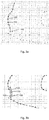
Fig. 4a depicts the situation when distance between positions is below a predefined distance. In this example,first reference location 110 is not used in combination withsecond reference location 120 that would be the next position, but rather with reference location 121, because usingsecond reference location 120 would result in an acute angle where therobot 10 has to move. - To avoid the unnecessary move of
robot 10 in an acute angle, Tight Corner Check method is used, as depicted inFig. 4b . For this, reference location 121 is used to determinedfirst target location 160. Thus, the acute angle situation is avoided. -
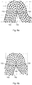
Fig. 5 depicts the situation when Separate Area Check applies. In this situation,second contour 101 is separated fromfirst contour 100, because all positions in bottleneck 103 have already been treated. In this situation, all n-tuples associated to positions in thefirst contour 100 are checked, if they have been used for determining the n-tuple 260 associated to thefirst target location 160. For this check, the n-tuples need an additional entry. - All n-tuples of the first contourthat have not been used - i.e. that are associated to fourth reference locations - must lie in the Separate Area, i.e. apart from the area that can be reached by the next round. These n-tuples build
second contour 101 and are candidates "to be treated later". However, the Separate Area withinsecond contour 101 may be so small, that therobot 10 has treated it already, e.g. because therobot 10 has an overlapping frame. To check this, each n-tuple 240 associated tofourth reference location 140 needs to be check against other reference locations within the Separate Area, i.e. against fifth reference locations 141. Then, all n-tuples that fulfil a distance criterion - say: their distance is biggerthan the predefined distance pd - must be treated later, indeed. Forthis, thesecond contour 101 consists of these positions. Positions with distance smaller than predefined distance pd are deleted from the list "candidates to be treated later" ofsecond contour 101. -
- 10
- moveable object, robot
- 100
- first contour
- 101
- second contour
- 102
- third contour
- 105
- first starting point
- 106
- second starting point
- 110
- first reference location
- 120
- second reference location
- 130
- third reference location
- 140, 141
- fourth, fifth reference location
- 150
- path
- 155
- smoothed path
- 160
- first target location
- 180
- known obstacle
- 165, 166
- first and second smoothed target location
- 210
- n-tuple (coordinate) of first reference location
- 220
- n-tuple (coordinate) of second reference location
- 230
- n-tuple (coordinate) of third reference location
- 260
- n-tuple (coordinate) of first target location
- 265, 266
- n-tuples of first and second smoothed target location
- 280
- n-tuple (coordinate) of known obstacle
- 300
- storage device
- 410
- start of procedure
- 420, 421, 422, 423
- steps to determine path
- 430, 431, 432, 433
- steps to determine smoothed path
- 440
- end of procedure
- pd
- predefined distance
- pn
- predefined number of reference locations
- sx, sy
- uncertainties of x or y
Claims (18)
- Method for determining a path (150) for a moveable object (10) in a physical area
by using at least a first reference location (110) and a second reference location (120) of the physical area,
wherein the first and the second reference location (110, 120) with an orientation information are comprised in a first contour (100),
wherein the path (150) comprises at least a first target location (160),
wherein the first target location (160) and the reference locations (110,120) are associated to a set of corresponding n-tuples (210,220,260),
whereby the set of n-tuples (210,220,260) specify the positions of the corresponding locations (110, 120, 160) in the physical area,
wherein the set of n-tuples (210, 220) of the first and the second reference location (110, 120) are stored in a storage device (300);
said method comprising at least the steps of:- retrieving from the storage device (300) at least the set of n-tuples (210, 220) associated to the first and the second reference location (110, 120);- determining the n-tuple (260) associated to the first target location (160) by using a first computational procedure, wherein the first computational procedure is based on orientation information and at least on the set of n-tuples (210, 220) associated to the first and the second reference location (110, 120);- storing the n-tuple (260) associated to the first target location (160) in the storage device (300). - Method according to claim 1,
wherein the orientation information is of Boolean type. - Method according to claim 1 or 2,
wherein the n-tuple (210, 220, 260) comprises at least the orientation information and
at least one x-coordinate and one y-coordinate and/or a function that represents at least a part of the first contour (100). - Method according to one of the preceding claims,
wherein the n-tuple (260) associated to the first target location (160) is determined by executing the first computational procedure comprising following steps:- dropping a perpendicular at a predefined point (215), preferably the half, of a line connecting first and the second reference location (110,120) associated to the set of n-tuples (210, 220);- determining a direction, based on the orientation information;- determining the first target location (160) either at the predefined point (215) or on said perpendicular at a pre-selected distance from the predefined point (215) in the determined direction. - Method according to one of the preceding claims,
wherein the n-tuple (260) associated to the first target location (160) is determined by executing the first computational procedure, based on orientation information and at least on the set of n-tuples (210, 220) associated to the first and the second reference location (110, 120) and a third n-tuple (230), which is also part of the first contour (100), associated to a third reference location (130), comprising following steps:- constructing a circle that includes the first, the second, and the third reference location (110, 120,130), wherein said second reference location (120) is between said first and said third reference location (110, 130);- determining a direction, based on the orientation information and the centre of said circle, on a line between second reference location (120) and said centre;- determining the first target location (160) on said line at a pre-selected distance from the second reference location (120). - Method according to claim 4 or 5,
wherein uncertainties associated with the reference locations (110,120) and/orthe current position of the moveable object (10) are subtracted from the pre-selected distance. - Method according to one of the preceding claims,
by using additionally first and second smoothed target locations (165,166) associated to a set of corresponding n-tuples (265, 266)
wherein, after determining the path (150) for the moveable object (10), a smoothed path (155) is determined for the moveable object (10), comprising at least the steps of:- retrieving from the storage device (300) at least the n-tuple (260) associated to the first target location (160);- determining the n-tuples (265, 266) associated to the first and second smoothed target locations (165, 166) by using a second computational procedure,
wherein the second computational procedure is based on the n-tuple (260) associated to the first target location (160);- storing the n-tuples (265, 266) associated to the first and second smoothed target locations (165, 166) in the storage device (300). - Method according to claim 7,
wherein the moveable object (10) moves on a smoothed path (155),
wherein the smoothed path (155) is calculated from the path (150) by using an interpolation method, particularly a polynomial interpolation or a spline interpolation, preferably a cubic spline algorithm. - Method according to claim 7,
wherein the smoothed path (155) comprises at least one reference location (110) of the first contour (100), from and/orto which the interpolation method is a straight line. - Method according to claim 7 or 8,
wherein the n-tuples (265, 266) associated to the first and second smoothed target locations (165, 166) are determined by a third computational procedure that provides the same distance between each pair of adjacent smoothed target locations (165, 166). - Method according to one of the preceding claims,
wherein the n-tuple (260) associated to the first target location (160) is compared with the first target location (160) in the physical area, or
or the n-tuples (265, 266) associated to the first and second smoothed target locations (165, 166) are compared with the first and second smoothed target locations (165, 166) in the physical area and, if differences appear between the n-tuples (265, 266) and the first and second smoothed target locations (165,166), the n-tuples (265,266) are corrected accordingly. - Method according to one of the preceding claims,
wherein the moveable object (10) starts determining the path (150) with a first starting point (105) that is comprised in the first contour (100) and,
when the first starting point (105) is used a second time for determining the path (150), the path (150) is transformed into the first contour (100). - Method according to one of the preceding claims,
wherein, when the distance between the first reference location (110) and a forth reference location (140) comprised in the first contour (100) is smallerthan a predefined distance (pd), the fourth reference location (140) is transformed into the second reference location (120). - Method according to one of the preceding claims,
wherein, when- the first starting point (105) is used a second time for determining the path (150) and- the distance between one reference location in the first contour (100) and at least one other reference location (140) in the first contour (100) has been found smaller than the predefined distance (pd),then a method with following steps is executed:- each fourth reference location in the first contour (100) is checked for having been used to determine the n-tuple (260) associated to the first target location (160);- each fourth reference location (140) that has not been used is checked if there is at least one fifth reference location (141) that has not been used and the distance between the fourth and the fifth reference location (140,141) is bigger than the predefined distance (pd);- all fifth reference locations (141) are transformed into a second contour (101). - Method according to one of the preceding claims,
wherein, when- the first starting point (105) is used for determining the path (150) a second time and- the number of reference locations in the first contour (100) is below a predefined number (pn),then- the moveable object (10) is moved to said reference locations in the first contour (100), and then- the number of reference locations in the first contour (100) is set to zero. - Method according to claim 15,
wherein, when- the number of reference locations in the first contour (100) is set to zero and- there is a second contour (101) with a number of reference locations greater than zerothen a method with following steps is executed:- retrieving from the storage device (300) all n-tuples that are defined as viable;- determining a cross-path between the first starting point (105) and at least one reference location in the second contour (101), by using a traversing method;- moving the moveable object (10) on the cross-path to the reference location in the second contour (101);- transforming the at least one reference location in the second contour (101) into the first starting point (105) and- transforming the second contour (101) into the first contour (100);otherwise stop the moveable object (10). - Method according to one of the preceding claims,
wherein at least one location (180) in the physical area associated to a corresponding n-tuple (280) can be defined as a special contour, namely as an obstacle. - Method according to one of the preceding claims,
wherein, when the first target location (160) associated to the determined the n-tuple (260) is not reachable, at least following steps are executed:- transforming all n-tuples associated to the path (150) and the reference locations of the first contour (100) that have not been used yet for determining the n-tuple (260) associated to the first target location (160) to a third contour (103);- transforming the third contour (103) into the first contour (100) by inverting the order of the n-tuples and inverting the orientation information.
Applications Claiming Priority (1)
| Application Number | Priority Date | Filing Date | Title |
|---|---|---|---|
| DE102016120460 | 2016-10-26 |
Publications (3)
| Publication Number | Publication Date |
|---|---|
| EP3316065A1 true EP3316065A1 (en) | 2018-05-02 |
| EP3316065B1 EP3316065B1 (en) | 2024-02-14 |
| EP3316065C0 EP3316065C0 (en) | 2024-02-14 |
Family
ID=60382016
Family Applications (1)
| Application Number | Title | Priority Date | Filing Date |
|---|---|---|---|
| EP17198570.8A Active EP3316065B1 (en) | 2016-10-26 | 2017-10-26 | Method for determining a path |
Country Status (2)
| Country | Link |
|---|---|
| EP (1) | EP3316065B1 (en) |
| CN (1) | CN107990906B (en) |
Cited By (4)
| Publication number | Priority date | Publication date | Assignee | Title |
|---|---|---|---|---|
| US20220374019A1 (en) * | 2021-05-24 | 2022-11-24 | Trimble Inc. | Area coverage planner |
| CN116520862A (en) * | 2023-06-30 | 2023-08-01 | 青岛哈尔滨工程大学创新发展中心 | AUV task allocation method for multi-objective optimization under influence of ocean currents |
| US11814074B2 (en) | 2020-04-30 | 2023-11-14 | Trimble Inc. | Headland-following turns |
| US11874665B2 (en) | 2021-05-24 | 2024-01-16 | Trimble Inc. | Area coverage planner with replenishment planner |
Families Citing this family (2)
| Publication number | Priority date | Publication date | Assignee | Title |
|---|---|---|---|---|
| CN110136221B (en) * | 2019-04-12 | 2023-04-11 | 阿波罗智联(北京)科技有限公司 | Preprocessing method and device for drawing navigation map layer |
| CN110617817B (en) * | 2019-09-29 | 2022-04-08 | 阿波罗智联(北京)科技有限公司 | Navigation route determining method, device, equipment and storage medium |
Citations (5)
| Publication number | Priority date | Publication date | Assignee | Title |
|---|---|---|---|---|
| US5995902A (en) * | 1997-05-29 | 1999-11-30 | Ag-Chem Equipment Co., Inc. | Proactive swath planning system for assisting and guiding a vehicle operator |
| US6876920B1 (en) * | 1998-10-27 | 2005-04-05 | Beeline Technologies Pty Ltd | Vehicle positioning apparatus and method |
| US20060178823A1 (en) * | 2005-02-04 | 2006-08-10 | Novariant, Inc. | System and method for propagating agricultural vehicle guidance paths that have varying curvature along their length |
| EP1916584A2 (en) * | 2006-10-27 | 2008-04-30 | CNH Belgium N.V. | Nudge compensation for curved swath paths |
| EP2749983A2 (en) | 2012-11-12 | 2014-07-02 | Einhell Germany AG | Device and method for determining position |
Family Cites Families (1)
| Publication number | Priority date | Publication date | Assignee | Title |
|---|---|---|---|---|
| US20120290165A1 (en) * | 2011-05-09 | 2012-11-15 | Chien Ouyang | Flexible Robotic Mower |
-
2017
- 2017-10-26 CN CN201711012716.3A patent/CN107990906B/en active Active
- 2017-10-26 EP EP17198570.8A patent/EP3316065B1/en active Active
Patent Citations (5)
| Publication number | Priority date | Publication date | Assignee | Title |
|---|---|---|---|---|
| US5995902A (en) * | 1997-05-29 | 1999-11-30 | Ag-Chem Equipment Co., Inc. | Proactive swath planning system for assisting and guiding a vehicle operator |
| US6876920B1 (en) * | 1998-10-27 | 2005-04-05 | Beeline Technologies Pty Ltd | Vehicle positioning apparatus and method |
| US20060178823A1 (en) * | 2005-02-04 | 2006-08-10 | Novariant, Inc. | System and method for propagating agricultural vehicle guidance paths that have varying curvature along their length |
| EP1916584A2 (en) * | 2006-10-27 | 2008-04-30 | CNH Belgium N.V. | Nudge compensation for curved swath paths |
| EP2749983A2 (en) | 2012-11-12 | 2014-07-02 | Einhell Germany AG | Device and method for determining position |
Cited By (6)
| Publication number | Priority date | Publication date | Assignee | Title |
|---|---|---|---|---|
| US11814074B2 (en) | 2020-04-30 | 2023-11-14 | Trimble Inc. | Headland-following turns |
| US20220374019A1 (en) * | 2021-05-24 | 2022-11-24 | Trimble Inc. | Area coverage planner |
| US11860635B2 (en) * | 2021-05-24 | 2024-01-02 | Trimble Inc. | Area coverage planner |
| US11874665B2 (en) | 2021-05-24 | 2024-01-16 | Trimble Inc. | Area coverage planner with replenishment planner |
| CN116520862A (en) * | 2023-06-30 | 2023-08-01 | 青岛哈尔滨工程大学创新发展中心 | AUV task allocation method for multi-objective optimization under influence of ocean currents |
| CN116520862B (en) * | 2023-06-30 | 2023-09-29 | 青岛哈尔滨工程大学创新发展中心 | AUV task allocation method for multi-objective optimization under influence of ocean currents |
Also Published As
| Publication number | Publication date |
|---|---|
| EP3316065B1 (en) | 2024-02-14 |
| CN107990906A (en) | 2018-05-04 |
| CN107990906B (en) | 2022-06-17 |
| EP3316065C0 (en) | 2024-02-14 |
Similar Documents
| Publication | Publication Date | Title |
|---|---|---|
| EP3316065B1 (en) | Method for determining a path | |
| US10124488B2 (en) | Robot control system and method for planning driving path of robot | |
| EP3504602B1 (en) | Materials handling vehicle path validation and dynamic path modification | |
| KR101585504B1 (en) | Method and apparatus for generating pathe of autonomous vehicle | |
| US4862373A (en) | Method for providing a collision free path in a three-dimensional space | |
| US9616889B2 (en) | Cruise control system and method | |
| CN114355923B (en) | MPC-based track planning and tracking method under A-guidance | |
| CN112141091B (en) | Secondary parking method and system for solving parking space deviation and positioning deviation and vehicle | |
| CN108646765A (en) | Based on the quadruped robot paths planning method and system for improving A* algorithms | |
| JP5993784B2 (en) | Route correction device | |
| JP2022157259A (en) | System, method and work vehicle | |
| CN115808918A (en) | Global path planning method, motion control method and computer program product | |
| Fuji et al. | Trajectory planning for automated parking using multi-resolution state roadmap considering non-holonomic constraints | |
| CN113485346A (en) | Autonomous navigation method of mobile robot in nuclear accident complex environment | |
| WO2022124938A1 (en) | Robot motion planning method and mobile robot | |
| EP3498574A1 (en) | Method and system for guiding an autonomous vehicle in a forward path in real-time | |
| Xi et al. | A safe and efficient timed-elastic-band planner for unstructured environments | |
| JP6131587B2 (en) | Route correction device | |
| CN114637288A (en) | Mobile robot, method and device for controlling movement of mobile robot, and storage medium | |
| EP3480082A1 (en) | Method and system for autonomously steering a vehicle in a reverse path in real-time | |
| CN117382616B (en) | Path planning method and device, electronic equipment and storage medium | |
| KR102324099B1 (en) | Method for path planning of indoor moving robot and recording medium storing program for executing the same, and computer program stored in recording medium for executing the same | |
| WO2022247899A1 (en) | Traveling route planning method and apparatus, storage medium, and mobile apparatus | |
| JP2013134615A (en) | Route correction device | |
| Chiang et al. | Comparing path length by boundary following fast matching method and bug algorithms for path planning |
Legal Events
| Date | Code | Title | Description |
|---|---|---|---|
| PUAI | Public reference made under article 153(3) epc to a published international application that has entered the european phase |
Free format text: ORIGINAL CODE: 0009012 |
|
| STAA | Information on the status of an ep patent application or granted ep patent |
Free format text: STATUS: THE APPLICATION HAS BEEN PUBLISHED |
|
| AK | Designated contracting states |
Kind code of ref document: A1 Designated state(s): AL AT BE BG CH CY CZ DE DK EE ES FI FR GB GR HR HU IE IS IT LI LT LU LV MC MK MT NL NO PL PT RO RS SE SI SK SM TR |
|
| AX | Request for extension of the european patent |
Extension state: BA ME |
|
| STAA | Information on the status of an ep patent application or granted ep patent |
Free format text: STATUS: REQUEST FOR EXAMINATION WAS MADE |
|
| 17P | Request for examination filed |
Effective date: 20181031 |
|
| RBV | Designated contracting states (corrected) |
Designated state(s): AL AT BE BG CH CY CZ DE DK EE ES FI FR GB GR HR HU IE IS IT LI LT LU LV MC MK MT NL NO PL PT RO RS SE SI SK SM TR |
|
| STAA | Information on the status of an ep patent application or granted ep patent |
Free format text: STATUS: EXAMINATION IS IN PROGRESS |
|
| 17Q | First examination report despatched |
Effective date: 20200814 |
|
| GRAP | Despatch of communication of intention to grant a patent |
Free format text: ORIGINAL CODE: EPIDOSNIGR1 |
|
| STAA | Information on the status of an ep patent application or granted ep patent |
Free format text: STATUS: GRANT OF PATENT IS INTENDED |
|
| INTG | Intention to grant announced |
Effective date: 20230515 |
|
| GRAJ | Information related to disapproval of communication of intention to grant by the applicant or resumption of examination proceedings by the epo deleted |
Free format text: ORIGINAL CODE: EPIDOSDIGR1 |
|
| STAA | Information on the status of an ep patent application or granted ep patent |
Free format text: STATUS: EXAMINATION IS IN PROGRESS |
|
| INTC | Intention to grant announced (deleted) | ||
| GRAP | Despatch of communication of intention to grant a patent |
Free format text: ORIGINAL CODE: EPIDOSNIGR1 |
|
| STAA | Information on the status of an ep patent application or granted ep patent |
Free format text: STATUS: GRANT OF PATENT IS INTENDED |
|
| INTG | Intention to grant announced |
Effective date: 20230918 |
|
| GRAS | Grant fee paid |
Free format text: ORIGINAL CODE: EPIDOSNIGR3 |
|
| GRAA | (expected) grant |
Free format text: ORIGINAL CODE: 0009210 |
|
| STAA | Information on the status of an ep patent application or granted ep patent |
Free format text: STATUS: THE PATENT HAS BEEN GRANTED |
|
| AK | Designated contracting states |
Kind code of ref document: B1 Designated state(s): AL AT BE BG CH CY CZ DE DK EE ES FI FR GB GR HR HU IE IS IT LI LT LU LV MC MK MT NL NO PL PT RO RS SE SI SK SM TR |
|
| REG | Reference to a national code |
Ref country code: GB Ref legal event code: FG4D |
|
| REG | Reference to a national code |
Ref country code: CH Ref legal event code: EP |
|
| REG | Reference to a national code |
Ref country code: DE Ref legal event code: R096 Ref document number: 602017079108 Country of ref document: DE |
|
| REG | Reference to a national code |
Ref country code: IE Ref legal event code: FG4D |
|
| U01 | Request for unitary effect filed |
Effective date: 20240223 |
|
| U07 | Unitary effect registered |
Designated state(s): AT BE BG DE DK EE FI FR IT LT LU LV MT NL PT SE SI Effective date: 20240301 |
|
| REG | Reference to a national code |
Ref country code: LT Ref legal event code: MG9D |
|
| PG25 | Lapsed in a contracting state [announced via postgrant information from national office to epo] |
Ref country code: IS Free format text: LAPSE BECAUSE OF FAILURE TO SUBMIT A TRANSLATION OF THE DESCRIPTION OR TO PAY THE FEE WITHIN THE PRESCRIBED TIME-LIMIT Effective date: 20240614 |
|
| PG25 | Lapsed in a contracting state [announced via postgrant information from national office to epo] |
Ref country code: GR Free format text: LAPSE BECAUSE OF FAILURE TO SUBMIT A TRANSLATION OF THE DESCRIPTION OR TO PAY THE FEE WITHIN THE PRESCRIBED TIME-LIMIT Effective date: 20240515 |
|
| PG25 | Lapsed in a contracting state [announced via postgrant information from national office to epo] |
Ref country code: RS Free format text: LAPSE BECAUSE OF FAILURE TO SUBMIT A TRANSLATION OF THE DESCRIPTION OR TO PAY THE FEE WITHIN THE PRESCRIBED TIME-LIMIT Effective date: 20240514 Ref country code: HR Free format text: LAPSE BECAUSE OF FAILURE TO SUBMIT A TRANSLATION OF THE DESCRIPTION OR TO PAY THE FEE WITHIN THE PRESCRIBED TIME-LIMIT Effective date: 20240214 |
|
| PG25 | Lapsed in a contracting state [announced via postgrant information from national office to epo] |
Ref country code: ES Free format text: LAPSE BECAUSE OF FAILURE TO SUBMIT A TRANSLATION OF THE DESCRIPTION OR TO PAY THE FEE WITHIN THE PRESCRIBED TIME-LIMIT Effective date: 20240214 |
|
| PG25 | Lapsed in a contracting state [announced via postgrant information from national office to epo] |
Ref country code: RS Free format text: LAPSE BECAUSE OF FAILURE TO SUBMIT A TRANSLATION OF THE DESCRIPTION OR TO PAY THE FEE WITHIN THE PRESCRIBED TIME-LIMIT Effective date: 20240514 Ref country code: NO Free format text: LAPSE BECAUSE OF FAILURE TO SUBMIT A TRANSLATION OF THE DESCRIPTION OR TO PAY THE FEE WITHIN THE PRESCRIBED TIME-LIMIT Effective date: 20240514 Ref country code: IS Free format text: LAPSE BECAUSE OF FAILURE TO SUBMIT A TRANSLATION OF THE DESCRIPTION OR TO PAY THE FEE WITHIN THE PRESCRIBED TIME-LIMIT Effective date: 20240614 Ref country code: HR Free format text: LAPSE BECAUSE OF FAILURE TO SUBMIT A TRANSLATION OF THE DESCRIPTION OR TO PAY THE FEE WITHIN THE PRESCRIBED TIME-LIMIT Effective date: 20240214 Ref country code: GR Free format text: LAPSE BECAUSE OF FAILURE TO SUBMIT A TRANSLATION OF THE DESCRIPTION OR TO PAY THE FEE WITHIN THE PRESCRIBED TIME-LIMIT Effective date: 20240515 Ref country code: ES Free format text: LAPSE BECAUSE OF FAILURE TO SUBMIT A TRANSLATION OF THE DESCRIPTION OR TO PAY THE FEE WITHIN THE PRESCRIBED TIME-LIMIT Effective date: 20240214 |
|
| PG25 | Lapsed in a contracting state [announced via postgrant information from national office to epo] |
Ref country code: PL Free format text: LAPSE BECAUSE OF FAILURE TO SUBMIT A TRANSLATION OF THE DESCRIPTION OR TO PAY THE FEE WITHIN THE PRESCRIBED TIME-LIMIT Effective date: 20240214 |
|
| PG25 | Lapsed in a contracting state [announced via postgrant information from national office to epo] |
Ref country code: PL Free format text: LAPSE BECAUSE OF FAILURE TO SUBMIT A TRANSLATION OF THE DESCRIPTION OR TO PAY THE FEE WITHIN THE PRESCRIBED TIME-LIMIT Effective date: 20240214 |
|
| PG25 | Lapsed in a contracting state [announced via postgrant information from national office to epo] |
Ref country code: SM Free format text: LAPSE BECAUSE OF FAILURE TO SUBMIT A TRANSLATION OF THE DESCRIPTION OR TO PAY THE FEE WITHIN THE PRESCRIBED TIME-LIMIT Effective date: 20240214 |
|
| PG25 | Lapsed in a contracting state [announced via postgrant information from national office to epo] |
Ref country code: CZ Free format text: LAPSE BECAUSE OF FAILURE TO SUBMIT A TRANSLATION OF THE DESCRIPTION OR TO PAY THE FEE WITHIN THE PRESCRIBED TIME-LIMIT Effective date: 20240214 |
|
| PG25 | Lapsed in a contracting state [announced via postgrant information from national office to epo] |
Ref country code: SK Free format text: LAPSE BECAUSE OF FAILURE TO SUBMIT A TRANSLATION OF THE DESCRIPTION OR TO PAY THE FEE WITHIN THE PRESCRIBED TIME-LIMIT Effective date: 20240214 |
|
| PG25 | Lapsed in a contracting state [announced via postgrant information from national office to epo] |
Ref country code: SM Free format text: LAPSE BECAUSE OF FAILURE TO SUBMIT A TRANSLATION OF THE DESCRIPTION OR TO PAY THE FEE WITHIN THE PRESCRIBED TIME-LIMIT Effective date: 20240214 Ref country code: SK Free format text: LAPSE BECAUSE OF FAILURE TO SUBMIT A TRANSLATION OF THE DESCRIPTION OR TO PAY THE FEE WITHIN THE PRESCRIBED TIME-LIMIT Effective date: 20240214 Ref country code: RO Free format text: LAPSE BECAUSE OF FAILURE TO SUBMIT A TRANSLATION OF THE DESCRIPTION OR TO PAY THE FEE WITHIN THE PRESCRIBED TIME-LIMIT Effective date: 20240214 Ref country code: CZ Free format text: LAPSE BECAUSE OF FAILURE TO SUBMIT A TRANSLATION OF THE DESCRIPTION OR TO PAY THE FEE WITHIN THE PRESCRIBED TIME-LIMIT Effective date: 20240214 |
|
| REG | Reference to a national code |
Ref country code: DE Ref legal event code: R097 Ref document number: 602017079108 Country of ref document: DE |
|
| U20 | Renewal fee for the european patent with unitary effect paid |
Year of fee payment: 8 Effective date: 20241028 |
|
| PLBE | No opposition filed within time limit |
Free format text: ORIGINAL CODE: 0009261 |
|
| STAA | Information on the status of an ep patent application or granted ep patent |
Free format text: STATUS: NO OPPOSITION FILED WITHIN TIME LIMIT |
|
| 26N | No opposition filed |
Effective date: 20241115 |
|
| REG | Reference to a national code |
Ref country code: CH Ref legal event code: PL |
|
| GBPC | Gb: european patent ceased through non-payment of renewal fee |
Effective date: 20241026 |
|
| PG25 | Lapsed in a contracting state [announced via postgrant information from national office to epo] |
Ref country code: MC Free format text: LAPSE BECAUSE OF FAILURE TO SUBMIT A TRANSLATION OF THE DESCRIPTION OR TO PAY THE FEE WITHIN THE PRESCRIBED TIME-LIMIT Effective date: 20240214 |
|
| PG25 | Lapsed in a contracting state [announced via postgrant information from national office to epo] |
Ref country code: GB Free format text: LAPSE BECAUSE OF NON-PAYMENT OF DUE FEES Effective date: 20241026 |
|
| PG25 | Lapsed in a contracting state [announced via postgrant information from national office to epo] |
Ref country code: CH Free format text: LAPSE BECAUSE OF NON-PAYMENT OF DUE FEES Effective date: 20241031 |
|
| PG25 | Lapsed in a contracting state [announced via postgrant information from national office to epo] |
Ref country code: IE Free format text: LAPSE BECAUSE OF NON-PAYMENT OF DUE FEES Effective date: 20241026 |
|
| U20 | Renewal fee for the european patent with unitary effect paid |
Year of fee payment: 9 Effective date: 20251027 |
|
| PG25 | Lapsed in a contracting state [announced via postgrant information from national office to epo] |
Ref country code: CY Free format text: LAPSE BECAUSE OF FAILURE TO SUBMIT A TRANSLATION OF THE DESCRIPTION OR TO PAY THE FEE WITHIN THE PRESCRIBED TIME-LIMIT; INVALID AB INITIO Effective date: 20171026 |
|
| PG25 | Lapsed in a contracting state [announced via postgrant information from national office to epo] |
Ref country code: HU Free format text: LAPSE BECAUSE OF FAILURE TO SUBMIT A TRANSLATION OF THE DESCRIPTION OR TO PAY THE FEE WITHIN THE PRESCRIBED TIME-LIMIT; INVALID AB INITIO Effective date: 20171026 |