EP3315941A1 - Method of inspecting component abrasive surface with marking media - Google Patents
Method of inspecting component abrasive surface with marking media Download PDFInfo
- Publication number
- EP3315941A1 EP3315941A1 EP17196025.5A EP17196025A EP3315941A1 EP 3315941 A1 EP3315941 A1 EP 3315941A1 EP 17196025 A EP17196025 A EP 17196025A EP 3315941 A1 EP3315941 A1 EP 3315941A1
- Authority
- EP
- European Patent Office
- Prior art keywords
- particles
- set forth
- paper
- media
- imprint
- Prior art date
- Legal status (The legal status is an assumption and is not a legal conclusion. Google has not performed a legal analysis and makes no representation as to the accuracy of the status listed.)
- Granted
Links
Images


Classifications
-
- G—PHYSICS
- G01—MEASURING; TESTING
- G01M—TESTING STATIC OR DYNAMIC BALANCE OF MACHINES OR STRUCTURES; TESTING OF STRUCTURES OR APPARATUS, NOT OTHERWISE PROVIDED FOR
- G01M15/00—Testing of engines
- G01M15/14—Testing gas-turbine engines or jet-propulsion engines
-
- G—PHYSICS
- G01—MEASURING; TESTING
- G01B—MEASURING LENGTH, THICKNESS OR SIMILAR LINEAR DIMENSIONS; MEASURING ANGLES; MEASURING AREAS; MEASURING IRREGULARITIES OF SURFACES OR CONTOURS
- G01B5/00—Measuring arrangements characterised by the use of mechanical techniques
- G01B5/28—Measuring arrangements characterised by the use of mechanical techniques for measuring roughness or irregularity of surfaces
-
- G—PHYSICS
- G01—MEASURING; TESTING
- G01N—INVESTIGATING OR ANALYSING MATERIALS BY DETERMINING THEIR CHEMICAL OR PHYSICAL PROPERTIES
- G01N19/00—Investigating materials by mechanical methods
- G01N19/08—Detecting presence of flaws or irregularities
-
- F—MECHANICAL ENGINEERING; LIGHTING; HEATING; WEAPONS; BLASTING
- F05—INDEXING SCHEMES RELATING TO ENGINES OR PUMPS IN VARIOUS SUBCLASSES OF CLASSES F01-F04
- F05D—INDEXING SCHEME FOR ASPECTS RELATING TO NON-POSITIVE-DISPLACEMENT MACHINES OR ENGINES, GAS-TURBINES OR JET-PROPULSION PLANTS
- F05D2230/00—Manufacture
- F05D2230/72—Maintenance
Definitions
- This application relates to a method of inspecting whether a surface of a component needs repair by imprinting the surface onto a marking media.
- Gas turbine engines typically include a fan delivering air into a bypass duct as bypass air and further into a compressor. Air in the compressor is compressed and then delivered into a combustor where it is mixed with fuel and ignited. Products of this combustion pass downstream over turbine rotors driving them to rotate. It is desirable to maintain tight clearances between a radially outer portion of blades rotating with both the compressor and turbine rotors and outer housings or static structure.
- the abrasive surfaces wear and eventually need to be recoated. This is a procedure that would desirably be limited as it will typically require removal of the blade, and the abrasive coatings themselves are expensive. Still, the abrasive materials are recoated periodically, without regard to actual need.
- a method of evaluating the quality of a surface on a component comprises the steps of (a) contacting a surface of a component with a media and imprinting qualities of the surface with the media; and (b) evaluating the imprint to determine the quality of the surface of the component.
- the surface of the component includes a plurality of particles and the quality includes whether the particles have worn such that they should be replaced.
- the component is a blade for a gas turbine engine.
- the particles are abrasive particles on a rotating blade in a gas turbine engine.
- the media includes a marking paper.
- the marking paper passes an imprint from the surface onto a second piece of paper.
- a size of an average imprint on the second paper is evaluated to determine whether the particles should be replaced.
- a percentage of mark on the second piece of paper per unit area of the paper is compared to a limit to identify whether the particles should be replaced.
- a size of an average imprint is evaluated to determine whether the particles should be replaced.
- a percentage of mark per unit area is compared to a limit to identify whether the particles should be replaced.
- the particles are abrasive particles on a rotating blade in a gas turbine engine.
- an absence of particles is also identified as part of the quality determination.
- an imprint from the media on the particles is evaluated to make the quality determination.
- the media includes a marking paper.
- a size of an average imprint is evaluated to determine whether the particles should be replaced.
- a percentage of mark per unit is compared to a limit to identify whether the particles should be replaced.
- the method is performed after the component is resurfaced.
- a gauge is utilized to ensure a controllable force provides a contact of step (a).
- the size of the average imprint is evaluated to determine whether the particles should be replaced.
- a percentage of mark per unit area of the paper is compared to a limit to identify whether the particles should be replaced.
- FIG. 1A schematically illustrates a gas turbine engine 20.
- the gas turbine engine 20 is disclosed herein as a two-spool turbofan that generally incorporates a fan section 22, a compressor section 24, a combustor section 26 and a turbine section 28.
- Alternative engines might include an augmentor section (not shown) among other systems or features.
- the fan section 22 drives air along a bypass flow path B in a bypass duct defined within a nacelle 15, while the compressor section 24 drives air along a core flow path C for compression and communication into the combustor section 26 then expansion through the turbine section 28.
- the exemplary engine 20 generally includes a low speed spool 30 and a high speed spool 32 mounted for rotation about an engine central longitudinal axis A relative to an engine static structure 36 via several bearing systems 38. It should be understood that various bearing systems 38 at various locations may alternatively or additionally be provided, and the location of bearing systems 38 may be varied as appropriate to the application.
- the low speed spool 30 generally includes an inner shaft 40 that interconnects a fan 42, a first (or low) pressure compressor 44 and a first (or low) pressure turbine 46.
- the inner shaft 40 is connected to the fan 42 through a speed change mechanism, which in exemplary gas turbine engine 20 is illustrated as a geared architecture 48 to drive the fan 42 at a lower speed than the low speed spool 30.
- the high speed spool 32 includes an outer shaft 50 that interconnects a second (or high) pressure compressor 52 and a second (or high) pressure turbine 54.
- a combustor 56 is arranged in exemplary gas turbine 20 between the high pressure compressor 52 and the high pressure turbine 54.
- a mid-turbine frame 57 of the engine static structure 36 is arranged generally between the high pressure turbine 54 and the low pressure turbine 46.
- the mid-turbine frame 57 further supports bearing systems 38 in the turbine section 28.
- the inner shaft 40 and the outer shaft 50 are concentric and rotate via bearing systems 38 about the engine central longitudinal axis A which is collinear with their longitudinal axes.
- the core airflow is compressed by the low pressure compressor 44 then the high pressure compressor 52, mixed and burned with fuel in the combustor 56, then expanded over the high pressure turbine 54 and low pressure turbine 46.
- the mid-turbine frame 57 includes airfoils 59 which are in the core airflow path C.
- the turbines 46, 54 rotationally drive the respective low speed spool 30 and high speed spool 32 in response to the expansion.
- gear system 48 may be located aft of combustor section 26 or even aft of turbine section 28, and fan section 22 may be positioned forward or aft of the location of gear system 48.
- the engine 20 in one example is a high-bypass geared aircraft engine.
- the engine 20 bypass ratio is greater than about six (6), with an example embodiment being greater than about ten (10)
- the geared architecture 48 is an epicyclic gear train, such as a planetary gear system or other gear system, with a gear reduction ratio of greater than about 2.3
- the low pressure turbine 46 has a pressure ratio that is greater than about five.
- the engine 20 bypass ratio is greater than about ten (10:1)
- the fan diameter is significantly larger than that of the low pressure compressor 44
- the low pressure turbine 46 has a pressure ratio that is greater than about five 5:1.
- Low pressure turbine 46 pressure ratio is pressure measured prior to inlet of low pressure turbine 46 as related to the pressure at the outlet of the low pressure turbine 46 prior to an exhaust nozzle.
- the geared architecture 48 may be an epicycle gear train, such as a planetary gear system or other gear system, with a gear reduction ratio of greater than about 2.3:1. It should be understood, however, that the above parameters are only exemplary of one embodiment of a geared architecture engine and that the present invention is applicable to other gas turbine engines including direct drive turbofans.
- the fan section 22 of the engine 20 is designed for a particular flight condition -- typically cruise at about 0.8 Mach and about 35,000 feet (10,668 meters).
- the flight condition of 0.8 Mach and 35,000 ft (10,668 meters), with the engine at its best fuel consumption - also known as "bucket cruise Thrust Specific Fuel Consumption ('TSFC')" - is the industry standard parameter of lbm of fuel being burned divided by lbf of thrust the engine produces at that minimum point.
- "Low fan pressure ratio” is the pressure ratio across the fan blade alone, without a Fan Exit Guide Vane (“FEGV”) system.
- the low fan pressure ratio as disclosed herein according to one non-limiting embodiment is less than about 1.45.
- Low corrected fan tip speed is the actual fan tip speed in ft/sec divided by an industry standard temperature correction of [(Tram °R) / (518.7 °R)] 0.5 .
- the "Low corrected fan tip speed” as disclosed herein according to one non-limiting embodiment is less than about 1150 ft / second (350.5 meters/second).
- Figure 1B schematically shows a compressor blade row 120.
- a rotor 122 receives a plurality of blades 124 each having a radially outer tip 126 (only one shown).
- An abradable seal 128 is positioned outwardly of tip 126.
- the blade 124 has a coating 129 on its outer tip 126 and there are abrasive particles 130 in that coating 129.
- Example coatings could be cBN abrasive particles in a nickel matrix.
- aluminum oxide based abrasive grit may be utilized.
- many other abrasives may be utilized.
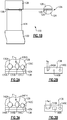
- Figure 2A shows a method of inspecting whether recoating is required for the abrasive particles 130.
- the abrasive material is in particle form, such as 130A, 130B, and 130C.
- the particles are unworn and have pointed tips 131A, 131B, and 131C.
- a marking paper 134 is placed to be contacted by the tips 131A, 131B, and 131C.
- a second piece of paper 136 is placed on the opposed side of the marking paper 134.
- a force F is applied, forcing the paper 134 against tips 131A, 131B, and 131C.
- the marking paper may be similar to that known as articulating paper which is used for dentistry purposes. On the other hand, any media which passes an imprint from the tips 131A, 131B, and 131C or merely captures an imprint may be utilized.
- the term "marking paper” as utilized in this application should be interpreted to broadly cover any such media.
- One acceptable marking paper is available under the trade name Bausch Articulating Paper.
- the second piece of paper 136 has small imprints 140A, 140B, and 140C from the marking paper 134. As shown, a contact diameter a u as associated with the mark 140A is relatively small. This is how the marks from an unworn blade or a blade that is not in need of recoating may appear.
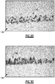
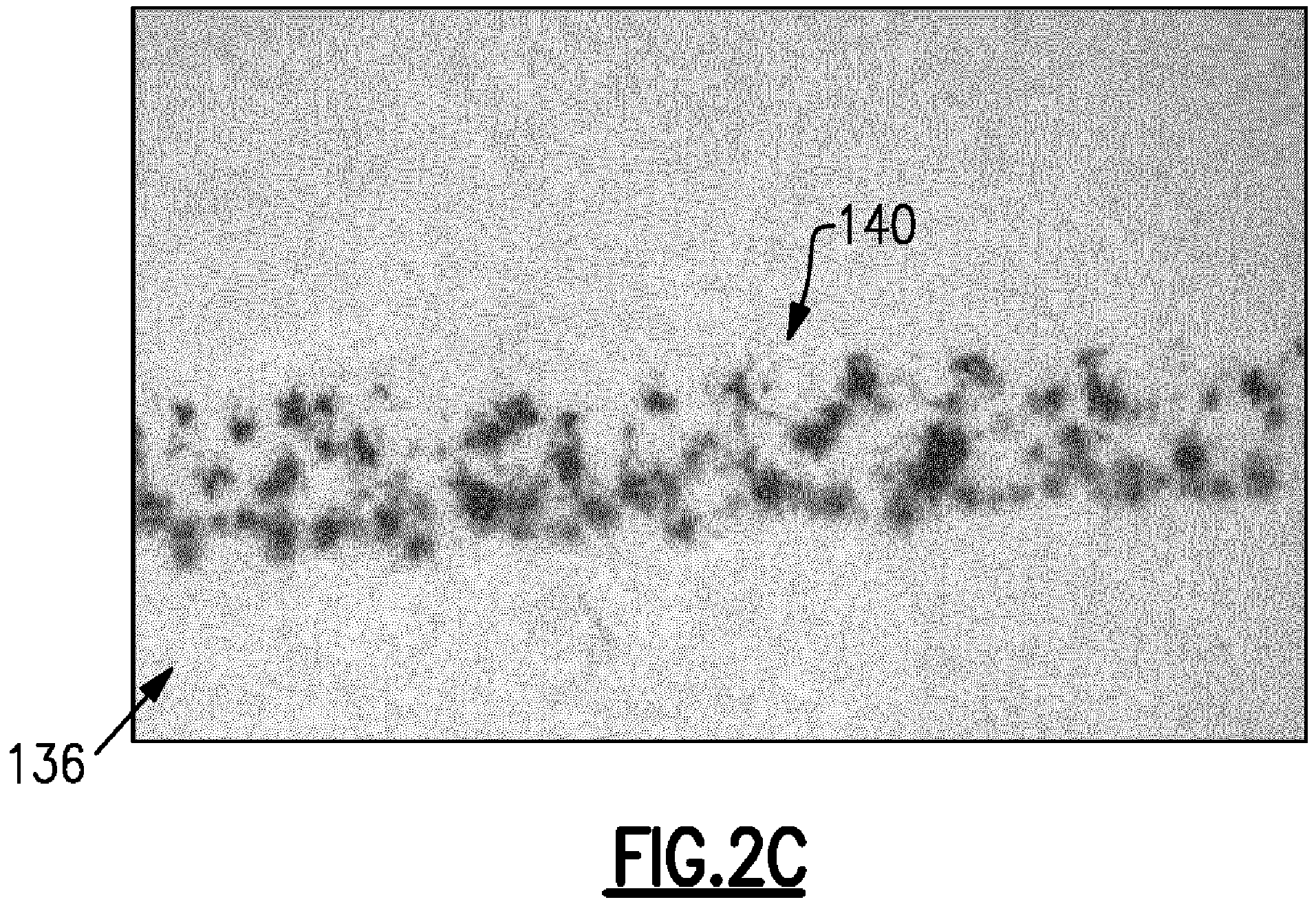
- Figure 2C shows a more real world photograph of what the paper 136 may look like with a number of marks 140.
- FIG 3A shows another occurrence of the method shown in Figure 2A , however, now the abrasive particles 142A, 142B, and 142C have worn and may be in need of being recoated.
- the tips are no longer pointed, but rather as shown at 144A, 144B, and 144C, they are relatively flat.
- the force F is applied and the marks are formed on the paper 136 as shown in Figure 3B .
- the marks can be seen to be much wider and cover a greater surface area as shown at 146A, 146B, and 146C compared to those in Figure 2B .
- a contact width a w is shown to be much greater than that shown at a u .
- the contact width is then correlated to the amount and percent wear of the tip.
- Figure 3C shows a real world example of the coverage of the marked area 146 from such a worn blade.
- the size may be compared to a limit and a need for recoating may be identified based upon that comparison.
- the area of mark per area media may be compared to a limit to identify the need for recoating.
- a limit to identify the need for recoating As an example, by comparing Figure 2C and Figure 3C , it is evident that a greater surface area is covered by the marks 146 of the worn blade than of the mark 140 of the blade which is not in need of being recoated.
- Figure 4A shows other potential features.
- a gauge 150 may press the paper 154 against the blade 152.
- the gauge 150 will ensure a controllable force be applied to the paper to provide the contact force as described above.
- particle 156 is shown in the blade 152, a void 158 where a particle may have been removed, may also be identified by this method. A missing particle would affect the percentage area, and thus the absence of particles is also identified as part of the quality determination.
- Figure 4B shows another embodiment.
- the blade 160 has a number of particle chips 162.
- the marking paper will change the color of the chips 162, and rather than evaluating the size, or area on the paper, such can be done on the blade.
- the imprint of the media on the particles is evaluated to make the quality determination.
- FIG. 5 is a flowchart of the method showing the steps of this disclosure.
- an imprint of the blade is made on media.
- the size, or the percentage area of mark is compared to a limit.
- the media may be separate from the marking paper, as disclosed above, or the imprints may somehow be on the marking paper.
- a need for recoating is identified based upon this comparison.
- the "media” may be the marking paper 134 and separate paper 136 in combination, or alternatively just a piece of marking paper.
- the method of this disclosure can be utilized to determine the quality of the coating after the coating has occurred.
Landscapes
- General Physics & Mathematics (AREA)
- Physics & Mathematics (AREA)
- Chemical & Material Sciences (AREA)
- General Health & Medical Sciences (AREA)
- Analytical Chemistry (AREA)
- Biochemistry (AREA)
- Life Sciences & Earth Sciences (AREA)
- Health & Medical Sciences (AREA)
- Immunology (AREA)
- Pathology (AREA)
- Engineering & Computer Science (AREA)
- Combustion & Propulsion (AREA)
- Turbine Rotor Nozzle Sealing (AREA)
- Structures Of Non-Positive Displacement Pumps (AREA)
Abstract
Description
- This application relates to a method of inspecting whether a surface of a component needs repair by imprinting the surface onto a marking media.
- Gas turbine engines are known and typically include a fan delivering air into a bypass duct as bypass air and further into a compressor. Air in the compressor is compressed and then delivered into a combustor where it is mixed with fuel and ignited. Products of this combustion pass downstream over turbine rotors driving them to rotate. It is desirable to maintain tight clearances between a radially outer portion of blades rotating with both the compressor and turbine rotors and outer housings or static structure.
- Thus, it is known to put an abradable seal radially outwardly of the blades in a compressor and turbine section. The outer tips of the blades may be provided with an abrasive surface to wear into the abradable seal. In particular, abrasive surfaces are applied to the radially outer portion of the compressor blades.
- The abrasive surfaces wear and eventually need to be recoated. This is a procedure that would desirably be limited as it will typically require removal of the blade, and the abrasive coatings themselves are expensive. Still, the abrasive materials are recoated periodically, without regard to actual need.
- In a featured embodiment, a method of evaluating the quality of a surface on a component comprises the steps of (a) contacting a surface of a component with a media and imprinting qualities of the surface with the media; and (b) evaluating the imprint to determine the quality of the surface of the component.
- In another embodiment according to the previous embodiment, the surface of the component includes a plurality of particles and the quality includes whether the particles have worn such that they should be replaced.
- In another embodiment according to any of the previous embodiments, the component is a blade for a gas turbine engine.
- In another embodiment according to any of the previous embodiments, the particles are abrasive particles on a rotating blade in a gas turbine engine.
- In another embodiment according to any of the previous embodiments, the media includes a marking paper.
- In another embodiment according to any of the previous embodiments, the marking paper passes an imprint from the surface onto a second piece of paper.
- In another embodiment according to any of the previous embodiments, a size of an average imprint on the second paper is evaluated to determine whether the particles should be replaced.
- In another embodiment according to any of the previous embodiments, a percentage of mark on the second piece of paper per unit area of the paper is compared to a limit to identify whether the particles should be replaced.
- In another embodiment according to any of the previous embodiments, a size of an average imprint is evaluated to determine whether the particles should be replaced.
- In another embodiment according to any of the previous embodiments, a percentage of mark per unit area is compared to a limit to identify whether the particles should be replaced.
- In another embodiment according to any of the previous embodiments, the particles are abrasive particles on a rotating blade in a gas turbine engine.
- In another embodiment according to any of the previous embodiments, an absence of particles is also identified as part of the quality determination.
- In another embodiment according to any of the previous embodiments, an imprint from the media on the particles is evaluated to make the quality determination.
- In another embodiment according to any of the previous embodiments, the media includes a marking paper.
- In another embodiment according to any of the previous embodiments, a size of an average imprint is evaluated to determine whether the particles should be replaced.
- In another embodiment according to any of the previous embodiments, a percentage of mark per unit is compared to a limit to identify whether the particles should be replaced.
- In another embodiment according to any of the previous embodiments, the method is performed after the component is resurfaced.
- In another embodiment according to any of the previous embodiments, a gauge is utilized to ensure a controllable force provides a contact of step (a).
- In another embodiment according to any of the previous embodiments, the size of the average imprint is evaluated to determine whether the particles should be replaced.
- In another embodiment according to any of the previous embodiments, a percentage of mark per unit area of the paper is compared to a limit to identify whether the particles should be replaced.
- These and other features may be best understood from the following drawings and specification.
-
-
Figure 1A schematically shows a gas turbine engine. -
Figure 1B shows a compressor blade. -
Figure 2A shows a first step in a method. -
Figure 2B shows a subsequent step. -
Figure 2C is a more real world view ofFigure 2B . -
Figure 3A shows another method step. -
Figure 3B shows a portion of a subsequent step. -
Figure 3C is a more real world version ofFigure 3B . -
Figure 4A shows another possible scenario. -
Figure 4B shows yet another method embodiment. -
Figure 5 shows a flowchart. -
Figure 1A schematically illustrates agas turbine engine 20. Thegas turbine engine 20 is disclosed herein as a two-spool turbofan that generally incorporates afan section 22, acompressor section 24, a combustor section 26 and aturbine section 28. Alternative engines might include an augmentor section (not shown) among other systems or features. Thefan section 22 drives air along a bypass flow path B in a bypass duct defined within anacelle 15, while thecompressor section 24 drives air along a core flow path C for compression and communication into the combustor section 26 then expansion through theturbine section 28. Although depicted as a two-spool turbofan gas turbine engine in the disclosed non-limiting embodiment, it should be understood that the concepts described herein are not limited to use with two-spool turbofans as the teachings may be applied to other types of turbine engines including three-spool architectures. - The
exemplary engine 20 generally includes alow speed spool 30 and ahigh speed spool 32 mounted for rotation about an engine central longitudinal axis A relative to an engine static structure 36 viaseveral bearing systems 38. It should be understood thatvarious bearing systems 38 at various locations may alternatively or additionally be provided, and the location ofbearing systems 38 may be varied as appropriate to the application. - The
low speed spool 30 generally includes aninner shaft 40 that interconnects afan 42, a first (or low)pressure compressor 44 and a first (or low)pressure turbine 46. Theinner shaft 40 is connected to thefan 42 through a speed change mechanism, which in exemplarygas turbine engine 20 is illustrated as a gearedarchitecture 48 to drive thefan 42 at a lower speed than thelow speed spool 30. Thehigh speed spool 32 includes anouter shaft 50 that interconnects a second (or high)pressure compressor 52 and a second (or high)pressure turbine 54. Acombustor 56 is arranged inexemplary gas turbine 20 between thehigh pressure compressor 52 and thehigh pressure turbine 54. Amid-turbine frame 57 of the engine static structure 36 is arranged generally between thehigh pressure turbine 54 and thelow pressure turbine 46. Themid-turbine frame 57 further supports bearingsystems 38 in theturbine section 28. Theinner shaft 40 and theouter shaft 50 are concentric and rotate viabearing systems 38 about the engine central longitudinal axis A which is collinear with their longitudinal axes. - The core airflow is compressed by the
low pressure compressor 44 then thehigh pressure compressor 52, mixed and burned with fuel in thecombustor 56, then expanded over thehigh pressure turbine 54 andlow pressure turbine 46. Themid-turbine frame 57 includesairfoils 59 which are in the core airflow path C. Theturbines low speed spool 30 andhigh speed spool 32 in response to the expansion. It will be appreciated that each of the positions of thefan section 22,compressor section 24, combustor section 26,turbine section 28, and fandrive gear system 48 may be varied. For example,gear system 48 may be located aft of combustor section 26 or even aft ofturbine section 28, andfan section 22 may be positioned forward or aft of the location ofgear system 48. - The
engine 20 in one example is a high-bypass geared aircraft engine. In a further example, theengine 20 bypass ratio is greater than about six (6), with an example embodiment being greater than about ten (10), the gearedarchitecture 48 is an epicyclic gear train, such as a planetary gear system or other gear system, with a gear reduction ratio of greater than about 2.3 and thelow pressure turbine 46 has a pressure ratio that is greater than about five. In one disclosed embodiment, theengine 20 bypass ratio is greater than about ten (10:1), the fan diameter is significantly larger than that of thelow pressure compressor 44, and thelow pressure turbine 46 has a pressure ratio that is greater than about five 5:1.Low pressure turbine 46 pressure ratio is pressure measured prior to inlet oflow pressure turbine 46 as related to the pressure at the outlet of thelow pressure turbine 46 prior to an exhaust nozzle. The gearedarchitecture 48 may be an epicycle gear train, such as a planetary gear system or other gear system, with a gear reduction ratio of greater than about 2.3:1. It should be understood, however, that the above parameters are only exemplary of one embodiment of a geared architecture engine and that the present invention is applicable to other gas turbine engines including direct drive turbofans. - A significant amount of thrust is provided by the bypass flow B due to the high bypass ratio. The
fan section 22 of theengine 20 is designed for a particular flight condition -- typically cruise at about 0.8 Mach and about 35,000 feet (10,668 meters). The flight condition of 0.8 Mach and 35,000 ft (10,668 meters), with the engine at its best fuel consumption - also known as "bucket cruise Thrust Specific Fuel Consumption ('TSFC')" - is the industry standard parameter of lbm of fuel being burned divided by lbf of thrust the engine produces at that minimum point. "Low fan pressure ratio" is the pressure ratio across the fan blade alone, without a Fan Exit Guide Vane ("FEGV") system. The low fan pressure ratio as disclosed herein according to one non-limiting embodiment is less than about 1.45. "Low corrected fan tip speed" is the actual fan tip speed in ft/sec divided by an industry standard temperature correction of [(Tram °R) / (518.7 °R)]0.5. The "Low corrected fan tip speed" as disclosed herein according to one non-limiting embodiment is less than about 1150 ft / second (350.5 meters/second). -
Figure 1B schematically shows acompressor blade row 120. Arotor 122 receives a plurality ofblades 124 each having a radially outer tip 126 (only one shown). Anabradable seal 128 is positioned outwardly oftip 126. - Shown in a detail, the
blade 124 has acoating 129 on itsouter tip 126 and there areabrasive particles 130 in thatcoating 129. - Example coatings could be cBN abrasive particles in a nickel matrix. Alternatively, aluminum oxide based abrasive grit may be utilized. Of course, many other abrasives may be utilized.
-
Figure 2A shows a method of inspecting whether recoating is required for theabrasive particles 130. As shown, the abrasive material is in particle form, such as 130A, 130B, and 130C. The particles are unworn and have pointedtips - A marking
paper 134 is placed to be contacted by thetips paper 136 is placed on the opposed side of the markingpaper 134. A force F is applied, forcing thepaper 134 againsttips - The marking paper may be similar to that known as articulating paper which is used for dentistry purposes. On the other hand, any media which passes an imprint from the
tips - Now, as shown in
Figure 2B , the second piece ofpaper 136 hassmall imprints paper 134. As shown, a contact diameter au as associated with themark 140A is relatively small. This is how the marks from an unworn blade or a blade that is not in need of recoating may appear. -
Figure 2C shows a more real world photograph of what thepaper 136 may look like with a number ofmarks 140. -
Figure 3A shows another occurrence of the method shown inFigure 2A , however, now theabrasive particles paper 136 as shown inFigure 3B . The marks can be seen to be much wider and cover a greater surface area as shown at 146A, 146B, and 146C compared to those inFigure 2B . A contact width aw is shown to be much greater than that shown at au. The contact width is then correlated to the amount and percent wear of the tip. -
Figure 3C shows a real world example of the coverage of the markedarea 146 from such a worn blade. - A decision can be made that recoating is in order based upon a review of the size of the marks, say, on average. The size may be compared to a limit and a need for recoating may be identified based upon that comparison.
- Alternatively, the area of mark per area media may be compared to a limit to identify the need for recoating. As an example, by comparing
Figure 2C and Figure 3C , it is evident that a greater surface area is covered by themarks 146 of the worn blade than of themark 140 of the blade which is not in need of being recoated. -
Figure 4A shows other potential features. As shown as inFigure 4A , agauge 150 may press thepaper 154 against theblade 152. Thegauge 150 will ensure a controllable force be applied to the paper to provide the contact force as described above. In addition, whileparticle 156 is shown in theblade 152, a void 158 where a particle may have been removed, may also be identified by this method. A missing particle would affect the percentage area, and thus the absence of particles is also identified as part of the quality determination. -
Figure 4B shows another embodiment. Here, theblade 160 has a number ofparticle chips 162. The marking paper will change the color of thechips 162, and rather than evaluating the size, or area on the paper, such can be done on the blade. Thus, the imprint of the media on the particles is evaluated to make the quality determination. -
Figure 5 is a flowchart of the method showing the steps of this disclosure. At step 100, an imprint of the blade is made on media. At step 102, the size, or the percentage area of mark, is compared to a limit. The media may be separate from the marking paper, as disclosed above, or the imprints may somehow be on the marking paper. At step 104, a need for recoating is identified based upon this comparison. - Thus, for purposes of this application, the "media" may be the marking
paper 134 andseparate paper 136 in combination, or alternatively just a piece of marking paper. - While the method is disclosed as a way of determining whether abrasive coating on a gas turbine engine blade must be recoated, it should be understood that the broad teachings of this disclosure could extend to testing the surface quality of any number of other components.
- In addition, the method of this disclosure can be utilized to determine the quality of the coating after the coating has occurred.
- Although an embodiment of this invention has been disclosed, a worker of ordinary skill in this art would recognize that certain modifications would come within the scope of this invention. For that reason, the following claims should be studied to determine the true scope and content of this invention.
Claims (14)
- A method of evaluating the quality of a surface on a component comprising the steps of:(a) contacting a surface of a component with a media and imprinting qualities of the surface with the media; and(b) evaluating the imprint to determine the quality of the surface of the component.
- The method as set forth in claim 1, wherein the surface of the component includes a plurality of particles and the quality includes whether the particles have worn such that they should be replaced.
- The method as set forth in claim 1 or 2, wherein said component is a blade for a gas turbine engine.
- The method as set forth in claim 2 or 3, wherein the particles are abrasive particles on a rotating blade in a gas turbine engine.
- The method as set forth in any preceding claim, wherein the media includes a marking paper.
- The method as set forth in claim 5, wherein the marking paper passes an imprint from the surface onto a second piece of paper.
- The method as set forth in claim 6, wherein a size of an average imprint on the second paper is evaluated to determine whether the particles should be replaced.
- The method as set forth in claim 6, wherein a percentage of mark on the second piece of paper per unit area of the paper is compared to a limit to identify whether the particles should be replaced.
- The method as set forth in any one of claims 2-8, wherein an absence of particles is also identified as part of the quality determination.
- The method as set forth in any one of claim 2-9, wherein an imprint from the media on the particles is evaluated to make the quality determination.
- The method as set forth in any preceding claim, wherein said method is performed after the component is resurfaced.
- The method as set forth in any preceding claim, wherein a gauge is utilized to ensure a controllable force provides a contact of step (a).
- The method as set forth in any preceding claim, wherein a size of an average imprint is evaluated to determine whether the particles should be replaced.
- The method as set forth in any preceding claim, wherein a percentage of mark per unit area of the media is compared to a limit to identify whether the particles should be replaced.
Applications Claiming Priority (1)
| Application Number | Priority Date | Filing Date | Title |
|---|---|---|---|
| US15/334,452 US10527524B2 (en) | 2016-10-26 | 2016-10-26 | Method of inspecting component surface with marking media |
Publications (3)
| Publication Number | Publication Date |
|---|---|
| EP3315941A1 true EP3315941A1 (en) | 2018-05-02 |
| EP3315941B1 EP3315941B1 (en) | 2020-12-23 |
| EP3315941B8 EP3315941B8 (en) | 2021-04-07 |
Family
ID=60083794
Family Applications (1)
| Application Number | Title | Priority Date | Filing Date |
|---|---|---|---|
| EP17196025.5A Active EP3315941B8 (en) | 2016-10-26 | 2017-10-11 | Method of inspecting component abrasive surface with marking media |
Country Status (2)
| Country | Link |
|---|---|
| US (2) | US10527524B2 (en) |
| EP (1) | EP3315941B8 (en) |
Cited By (1)
| Publication number | Priority date | Publication date | Assignee | Title |
|---|---|---|---|---|
| CN109187335A (en) * | 2018-07-20 | 2019-01-11 | 郑州磨料磨具磨削研究所有限公司 | A kind of test device of diamond wire bonding agent to abrasive grain holding power |
Families Citing this family (5)
| Publication number | Priority date | Publication date | Assignee | Title |
|---|---|---|---|---|
| US10527524B2 (en) * | 2016-10-26 | 2020-01-07 | United Technologies Corporation | Method of inspecting component surface with marking media |
| CN114322723B (en) * | 2021-12-17 | 2022-12-09 | 江苏康业金属制品有限公司 | Multifunctional semi-automatic metal spool quality inspection device |
| US12442634B2 (en) | 2022-05-13 | 2025-10-14 | Rtx Corporation | Visual and/or dimensional tip inspection systems and methods |
| US12044632B2 (en) | 2022-05-13 | 2024-07-23 | Rtx Corporation | Airfoil tip cleaning and assessment systems and methods |
| US11725517B1 (en) * | 2022-05-13 | 2023-08-15 | Raytheon Technologies Corporation | Airfoil tip cleaning and assessment systems and methods |
Citations (3)
| Publication number | Priority date | Publication date | Assignee | Title |
|---|---|---|---|---|
| US3421223A (en) * | 1967-02-06 | 1969-01-14 | Pascal Co Inc | Tooth marking method and means |
| EP2233600A1 (en) * | 2009-03-26 | 2010-09-29 | Alstom Technology Ltd | Method for the protection of a thermal barrier coating system and a method for the renewal of such a protection |
| EP2962844A2 (en) * | 2014-07-03 | 2016-01-06 | Rolls-Royce Corporation | Visual indicator of coating thickness |
Family Cites Families (21)
| Publication number | Priority date | Publication date | Assignee | Title |
|---|---|---|---|---|
| US1978716A (en) | 1932-04-01 | 1934-10-30 | Silas A Morehouse | Razor blade lubricator |
| US2330257A (en) | 1939-01-14 | 1943-09-28 | John F Wallace | Process for making tampons |
| US3731687A (en) | 1971-07-16 | 1973-05-08 | J Glassman | Catamenial tampon |
| US3813781A (en) | 1973-09-04 | 1974-06-04 | A Forgione | Bruxism monitoring device |
| US3959881A (en) | 1975-04-25 | 1976-06-01 | Kokal Jr August | Bite intensity detecting articulating paper |
| US4547155A (en) | 1984-03-15 | 1985-10-15 | Adler Harold A | Shielded dental contact marker |
| DE69313065T2 (en) * | 1992-10-15 | 1997-12-11 | Fuji Photo Film Co Ltd | Pressure sensitive recording layer |
| US5326261A (en) | 1993-01-15 | 1994-07-05 | Rains Michael D | Dental marking product |
| DE59602988D1 (en) | 1995-06-22 | 1999-10-14 | Medivice Ltd Co | Tampon applicator |
| US5704759A (en) * | 1996-10-21 | 1998-01-06 | Alliedsignal Inc. | Abrasive tip/abradable shroud system and method for gas turbine compressor clearance control |
| US5941150A (en) | 1997-06-09 | 1999-08-24 | Kropf; Gary | Device for dispensing and holding articulating paper |
| US5935407A (en) * | 1997-11-06 | 1999-08-10 | Chromalloy Gas Turbine Corporation | Method for producing abrasive tips for gas turbine blades |
| US6592540B2 (en) | 2001-03-12 | 2003-07-15 | Decarlo Tracy | Tampon applicator with lubricated tip |
| US7190440B2 (en) * | 2002-09-17 | 2007-03-13 | Seagate Technology, Llc | Controlling compressive force using pressure sensitive film |
| US7810447B2 (en) | 2005-01-08 | 2010-10-12 | Deborah Manos | Articulating paper coating dispenser and method |
| US8219367B2 (en) * | 2005-12-20 | 2012-07-10 | Sintokogio, Ltd. | Method of estimating information on projection conditions by a projection machine and a device thereof |
| WO2014123841A1 (en) * | 2013-02-10 | 2014-08-14 | United Technologies Corporation | Removable film for airfoil surfaces |
| CN104000667A (en) * | 2014-04-04 | 2014-08-27 | 首都医科大学附属北京口腔医院 | Stress testing apparatus and lingual orthodontic force measuring apparatus |
| US10544698B2 (en) * | 2016-06-20 | 2020-01-28 | United Technologies Corporation | Air seal abrasive coating and method |
| US10527524B2 (en) * | 2016-10-26 | 2020-01-07 | United Technologies Corporation | Method of inspecting component surface with marking media |
| US12099894B2 (en) * | 2019-09-20 | 2024-09-24 | Rtx Corporation | Composite material marking and identification |
-
2016
- 2016-10-26 US US15/334,452 patent/US10527524B2/en active Active
-
2017
- 2017-10-11 EP EP17196025.5A patent/EP3315941B8/en active Active
-
2020
- 2020-01-06 US US16/734,818 patent/US11480500B2/en active Active
Patent Citations (3)
| Publication number | Priority date | Publication date | Assignee | Title |
|---|---|---|---|---|
| US3421223A (en) * | 1967-02-06 | 1969-01-14 | Pascal Co Inc | Tooth marking method and means |
| EP2233600A1 (en) * | 2009-03-26 | 2010-09-29 | Alstom Technology Ltd | Method for the protection of a thermal barrier coating system and a method for the renewal of such a protection |
| EP2962844A2 (en) * | 2014-07-03 | 2016-01-06 | Rolls-Royce Corporation | Visual indicator of coating thickness |
Cited By (2)
| Publication number | Priority date | Publication date | Assignee | Title |
|---|---|---|---|---|
| CN109187335A (en) * | 2018-07-20 | 2019-01-11 | 郑州磨料磨具磨削研究所有限公司 | A kind of test device of diamond wire bonding agent to abrasive grain holding power |
| CN109187335B (en) * | 2018-07-20 | 2021-06-18 | 郑州磨料磨具磨削研究所有限公司 | Testing arrangement of diamond wire bonding agent to grit power of controlling |
Also Published As
| Publication number | Publication date |
|---|---|
| US11480500B2 (en) | 2022-10-25 |
| US20200141836A1 (en) | 2020-05-07 |
| US20180113053A1 (en) | 2018-04-26 |
| EP3315941B8 (en) | 2021-04-07 |
| EP3315941B1 (en) | 2020-12-23 |
| US10527524B2 (en) | 2020-01-07 |
Similar Documents
| Publication | Publication Date | Title |
|---|---|---|
| EP3315941B1 (en) | Method of inspecting component abrasive surface with marking media | |
| US11840930B2 (en) | Component with feather seal slots for a gas turbine engine | |
| US20220290575A1 (en) | Feather seal for cmc boas | |
| US10890079B2 (en) | Gas turbine engine arc segments with arced walls | |
| EP3734018A1 (en) | Seal for a gas turbine engine | |
| US9796055B2 (en) | Turbine case retention hook with insert | |
| US11572795B2 (en) | System and method for manufacture of abrasive coating | |
| US10822983B2 (en) | Hydrostatic seal with abradable teeth for gas turbine engine | |
| US20180171462A1 (en) | Abradable seal and method of producing a seal | |
| US10167729B2 (en) | Knife edge with increased crack propagation life | |
| US9957814B2 (en) | Gas turbine engine component with film cooling hole with accumulator | |
| US12601295B2 (en) | Support structure for bearing compartment | |
| US20200040755A1 (en) | Structural support for blade outer air seal assembly | |
| EP2955332B1 (en) | Geared turbofan engine with gearbox seal | |
| EP3819474A1 (en) | Platform seal for a gas turbine engine | |
| US10753281B2 (en) | Ablatable shaft feature in a gas turbine engine | |
| US20200025029A1 (en) | Attachment block for blade outer air seal providing convection cooling | |
| US10961866B2 (en) | Attachment block for blade outer air seal providing impingement cooling | |
| US11028719B2 (en) | Brush seal repair method | |
| EP2986823A2 (en) | Gas turbine engine airfoil platform edge geometry |
Legal Events
| Date | Code | Title | Description |
|---|---|---|---|
| PUAI | Public reference made under article 153(3) epc to a published international application that has entered the european phase |
Free format text: ORIGINAL CODE: 0009012 |
|
| STAA | Information on the status of an ep patent application or granted ep patent |
Free format text: STATUS: THE APPLICATION HAS BEEN PUBLISHED |
|
| AK | Designated contracting states |
Kind code of ref document: A1 Designated state(s): AL AT BE BG CH CY CZ DE DK EE ES FI FR GB GR HR HU IE IS IT LI LT LU LV MC MK MT NL NO PL PT RO RS SE SI SK SM TR |
|
| AX | Request for extension of the european patent |
Extension state: BA ME |
|
| STAA | Information on the status of an ep patent application or granted ep patent |
Free format text: STATUS: REQUEST FOR EXAMINATION WAS MADE |
|
| 17P | Request for examination filed |
Effective date: 20181030 |
|
| RBV | Designated contracting states (corrected) |
Designated state(s): AL AT BE BG CH CY CZ DE DK EE ES FI FR GB GR HR HU IE IS IT LI LT LU LV MC MK MT NL NO PL PT RO RS SE SI SK SM TR |
|
| GRAP | Despatch of communication of intention to grant a patent |
Free format text: ORIGINAL CODE: EPIDOSNIGR1 |
|
| STAA | Information on the status of an ep patent application or granted ep patent |
Free format text: STATUS: GRANT OF PATENT IS INTENDED |
|
| RIC1 | Information provided on ipc code assigned before grant |
Ipc: G01N 19/08 20060101AFI20200529BHEP Ipc: G01B 5/28 20060101ALI20200529BHEP |
|
| INTG | Intention to grant announced |
Effective date: 20200706 |
|
| GRAS | Grant fee paid |
Free format text: ORIGINAL CODE: EPIDOSNIGR3 |
|
| GRAA | (expected) grant |
Free format text: ORIGINAL CODE: 0009210 |
|
| STAA | Information on the status of an ep patent application or granted ep patent |
Free format text: STATUS: THE PATENT HAS BEEN GRANTED |
|
| AK | Designated contracting states |
Kind code of ref document: B1 Designated state(s): AL AT BE BG CH CY CZ DE DK EE ES FI FR GB GR HR HU IE IS IT LI LT LU LV MC MK MT NL NO PL PT RO RS SE SI SK SM TR |
|
| REG | Reference to a national code |
Ref country code: GB Ref legal event code: FG4D |
|
| REG | Reference to a national code |
Ref country code: DE Ref legal event code: R096 Ref document number: 602017029913 Country of ref document: DE |
|
| REG | Reference to a national code |
Ref country code: AT Ref legal event code: REF Ref document number: 1348199 Country of ref document: AT Kind code of ref document: T Effective date: 20210115 |
|
| REG | Reference to a national code |
Ref country code: IE Ref legal event code: FG4D |
|
| REG | Reference to a national code |
Ref country code: CH Ref legal event code: PK Free format text: BERICHTIGUNG B8 |
|
| RAP2 | Party data changed (patent owner data changed or rights of a patent transferred) |
Owner name: RAYTHEON TECHNOLOGIES CORPORATION |
|
| PG25 | Lapsed in a contracting state [announced via postgrant information from national office to epo] |
Ref country code: FI Free format text: LAPSE BECAUSE OF FAILURE TO SUBMIT A TRANSLATION OF THE DESCRIPTION OR TO PAY THE FEE WITHIN THE PRESCRIBED TIME-LIMIT Effective date: 20201223 Ref country code: GR Free format text: LAPSE BECAUSE OF FAILURE TO SUBMIT A TRANSLATION OF THE DESCRIPTION OR TO PAY THE FEE WITHIN THE PRESCRIBED TIME-LIMIT Effective date: 20210324 Ref country code: NO Free format text: LAPSE BECAUSE OF FAILURE TO SUBMIT A TRANSLATION OF THE DESCRIPTION OR TO PAY THE FEE WITHIN THE PRESCRIBED TIME-LIMIT Effective date: 20210323 Ref country code: RS Free format text: LAPSE BECAUSE OF FAILURE TO SUBMIT A TRANSLATION OF THE DESCRIPTION OR TO PAY THE FEE WITHIN THE PRESCRIBED TIME-LIMIT Effective date: 20201223 |
|
| REG | Reference to a national code |
Ref country code: AT Ref legal event code: MK05 Ref document number: 1348199 Country of ref document: AT Kind code of ref document: T Effective date: 20201223 |
|
| REG | Reference to a national code |
Ref country code: NL Ref legal event code: MP Effective date: 20201223 |
|
| PG25 | Lapsed in a contracting state [announced via postgrant information from national office to epo] |
Ref country code: SE Free format text: LAPSE BECAUSE OF FAILURE TO SUBMIT A TRANSLATION OF THE DESCRIPTION OR TO PAY THE FEE WITHIN THE PRESCRIBED TIME-LIMIT Effective date: 20201223 Ref country code: BG Free format text: LAPSE BECAUSE OF FAILURE TO SUBMIT A TRANSLATION OF THE DESCRIPTION OR TO PAY THE FEE WITHIN THE PRESCRIBED TIME-LIMIT Effective date: 20210323 Ref country code: LV Free format text: LAPSE BECAUSE OF FAILURE TO SUBMIT A TRANSLATION OF THE DESCRIPTION OR TO PAY THE FEE WITHIN THE PRESCRIBED TIME-LIMIT Effective date: 20201223 |
|
| PG25 | Lapsed in a contracting state [announced via postgrant information from national office to epo] |
Ref country code: NL Free format text: LAPSE BECAUSE OF FAILURE TO SUBMIT A TRANSLATION OF THE DESCRIPTION OR TO PAY THE FEE WITHIN THE PRESCRIBED TIME-LIMIT Effective date: 20201223 Ref country code: HR Free format text: LAPSE BECAUSE OF FAILURE TO SUBMIT A TRANSLATION OF THE DESCRIPTION OR TO PAY THE FEE WITHIN THE PRESCRIBED TIME-LIMIT Effective date: 20201223 |
|
| REG | Reference to a national code |
Ref country code: LT Ref legal event code: MG9D |
|
| PG25 | Lapsed in a contracting state [announced via postgrant information from national office to epo] |
Ref country code: SK Free format text: LAPSE BECAUSE OF FAILURE TO SUBMIT A TRANSLATION OF THE DESCRIPTION OR TO PAY THE FEE WITHIN THE PRESCRIBED TIME-LIMIT Effective date: 20201223 Ref country code: RO Free format text: LAPSE BECAUSE OF FAILURE TO SUBMIT A TRANSLATION OF THE DESCRIPTION OR TO PAY THE FEE WITHIN THE PRESCRIBED TIME-LIMIT Effective date: 20201223 Ref country code: PT Free format text: LAPSE BECAUSE OF FAILURE TO SUBMIT A TRANSLATION OF THE DESCRIPTION OR TO PAY THE FEE WITHIN THE PRESCRIBED TIME-LIMIT Effective date: 20210423 Ref country code: SM Free format text: LAPSE BECAUSE OF FAILURE TO SUBMIT A TRANSLATION OF THE DESCRIPTION OR TO PAY THE FEE WITHIN THE PRESCRIBED TIME-LIMIT Effective date: 20201223 Ref country code: EE Free format text: LAPSE BECAUSE OF FAILURE TO SUBMIT A TRANSLATION OF THE DESCRIPTION OR TO PAY THE FEE WITHIN THE PRESCRIBED TIME-LIMIT Effective date: 20201223 Ref country code: LT Free format text: LAPSE BECAUSE OF FAILURE TO SUBMIT A TRANSLATION OF THE DESCRIPTION OR TO PAY THE FEE WITHIN THE PRESCRIBED TIME-LIMIT Effective date: 20201223 |
|
| PG25 | Lapsed in a contracting state [announced via postgrant information from national office to epo] |
Ref country code: PL Free format text: LAPSE BECAUSE OF FAILURE TO SUBMIT A TRANSLATION OF THE DESCRIPTION OR TO PAY THE FEE WITHIN THE PRESCRIBED TIME-LIMIT Effective date: 20201223 Ref country code: AT Free format text: LAPSE BECAUSE OF FAILURE TO SUBMIT A TRANSLATION OF THE DESCRIPTION OR TO PAY THE FEE WITHIN THE PRESCRIBED TIME-LIMIT Effective date: 20201223 |
|
| REG | Reference to a national code |
Ref country code: DE Ref legal event code: R097 Ref document number: 602017029913 Country of ref document: DE |
|
| PG25 | Lapsed in a contracting state [announced via postgrant information from national office to epo] |
Ref country code: IS Free format text: LAPSE BECAUSE OF FAILURE TO SUBMIT A TRANSLATION OF THE DESCRIPTION OR TO PAY THE FEE WITHIN THE PRESCRIBED TIME-LIMIT Effective date: 20210423 |
|
| PG25 | Lapsed in a contracting state [announced via postgrant information from national office to epo] |
Ref country code: AL Free format text: LAPSE BECAUSE OF FAILURE TO SUBMIT A TRANSLATION OF THE DESCRIPTION OR TO PAY THE FEE WITHIN THE PRESCRIBED TIME-LIMIT Effective date: 20201223 Ref country code: CZ Free format text: LAPSE BECAUSE OF FAILURE TO SUBMIT A TRANSLATION OF THE DESCRIPTION OR TO PAY THE FEE WITHIN THE PRESCRIBED TIME-LIMIT Effective date: 20201223 Ref country code: IT Free format text: LAPSE BECAUSE OF FAILURE TO SUBMIT A TRANSLATION OF THE DESCRIPTION OR TO PAY THE FEE WITHIN THE PRESCRIBED TIME-LIMIT Effective date: 20201223 |
|
| PLBE | No opposition filed within time limit |
Free format text: ORIGINAL CODE: 0009261 |
|
| STAA | Information on the status of an ep patent application or granted ep patent |
Free format text: STATUS: NO OPPOSITION FILED WITHIN TIME LIMIT |
|
| PG25 | Lapsed in a contracting state [announced via postgrant information from national office to epo] |
Ref country code: DK Free format text: LAPSE BECAUSE OF FAILURE TO SUBMIT A TRANSLATION OF THE DESCRIPTION OR TO PAY THE FEE WITHIN THE PRESCRIBED TIME-LIMIT Effective date: 20201223 |
|
| 26N | No opposition filed |
Effective date: 20210924 |
|
| PG25 | Lapsed in a contracting state [announced via postgrant information from national office to epo] |
Ref country code: ES Free format text: LAPSE BECAUSE OF FAILURE TO SUBMIT A TRANSLATION OF THE DESCRIPTION OR TO PAY THE FEE WITHIN THE PRESCRIBED TIME-LIMIT Effective date: 20201223 |
|
| PG25 | Lapsed in a contracting state [announced via postgrant information from national office to epo] |
Ref country code: SI Free format text: LAPSE BECAUSE OF FAILURE TO SUBMIT A TRANSLATION OF THE DESCRIPTION OR TO PAY THE FEE WITHIN THE PRESCRIBED TIME-LIMIT Effective date: 20201223 |
|
| REG | Reference to a national code |
Ref country code: CH Ref legal event code: PL |
|
| PG25 | Lapsed in a contracting state [announced via postgrant information from national office to epo] |
Ref country code: IS Free format text: LAPSE BECAUSE OF FAILURE TO SUBMIT A TRANSLATION OF THE DESCRIPTION OR TO PAY THE FEE WITHIN THE PRESCRIBED TIME-LIMIT Effective date: 20210423 |
|
| REG | Reference to a national code |
Ref country code: BE Ref legal event code: MM Effective date: 20211031 |
|
| PG25 | Lapsed in a contracting state [announced via postgrant information from national office to epo] |
Ref country code: MC Free format text: LAPSE BECAUSE OF FAILURE TO SUBMIT A TRANSLATION OF THE DESCRIPTION OR TO PAY THE FEE WITHIN THE PRESCRIBED TIME-LIMIT Effective date: 20201223 |
|
| PG25 | Lapsed in a contracting state [announced via postgrant information from national office to epo] |
Ref country code: LU Free format text: LAPSE BECAUSE OF NON-PAYMENT OF DUE FEES Effective date: 20211011 Ref country code: BE Free format text: LAPSE BECAUSE OF NON-PAYMENT OF DUE FEES Effective date: 20211031 |
|
| PG25 | Lapsed in a contracting state [announced via postgrant information from national office to epo] |
Ref country code: LI Free format text: LAPSE BECAUSE OF NON-PAYMENT OF DUE FEES Effective date: 20211031 Ref country code: CH Free format text: LAPSE BECAUSE OF NON-PAYMENT OF DUE FEES Effective date: 20211031 |
|
| PG25 | Lapsed in a contracting state [announced via postgrant information from national office to epo] |
Ref country code: IE Free format text: LAPSE BECAUSE OF NON-PAYMENT OF DUE FEES Effective date: 20211011 |
|
| PG25 | Lapsed in a contracting state [announced via postgrant information from national office to epo] |
Ref country code: HU Free format text: LAPSE BECAUSE OF FAILURE TO SUBMIT A TRANSLATION OF THE DESCRIPTION OR TO PAY THE FEE WITHIN THE PRESCRIBED TIME-LIMIT; INVALID AB INITIO Effective date: 20171011 |
|
| P01 | Opt-out of the competence of the unified patent court (upc) registered |
Effective date: 20230520 |
|
| PG25 | Lapsed in a contracting state [announced via postgrant information from national office to epo] |
Ref country code: CY Free format text: LAPSE BECAUSE OF FAILURE TO SUBMIT A TRANSLATION OF THE DESCRIPTION OR TO PAY THE FEE WITHIN THE PRESCRIBED TIME-LIMIT Effective date: 20201223 |
|
| PG25 | Lapsed in a contracting state [announced via postgrant information from national office to epo] |
Ref country code: MK Free format text: LAPSE BECAUSE OF FAILURE TO SUBMIT A TRANSLATION OF THE DESCRIPTION OR TO PAY THE FEE WITHIN THE PRESCRIBED TIME-LIMIT Effective date: 20201223 |
|
| PG25 | Lapsed in a contracting state [announced via postgrant information from national office to epo] |
Ref country code: MT Free format text: LAPSE BECAUSE OF FAILURE TO SUBMIT A TRANSLATION OF THE DESCRIPTION OR TO PAY THE FEE WITHIN THE PRESCRIBED TIME-LIMIT Effective date: 20201223 |
|
| REG | Reference to a national code |
Ref country code: DE Ref legal event code: R081 Ref document number: 602017029913 Country of ref document: DE Owner name: RTX CORPORATION (N.D.GES.D. STAATES DELAWARE),, US Free format text: FORMER OWNER: UNITED TECHNOLOGIES CORPORATION, FARMINGTON, CONN., US |
|
| PGFP | Annual fee paid to national office [announced via postgrant information from national office to epo] |
Ref country code: GB Payment date: 20250923 Year of fee payment: 9 |
|
| PGFP | Annual fee paid to national office [announced via postgrant information from national office to epo] |
Ref country code: FR Payment date: 20250924 Year of fee payment: 9 |
|
| PG25 | Lapsed in a contracting state [announced via postgrant information from national office to epo] |
Ref country code: TR Free format text: LAPSE BECAUSE OF FAILURE TO SUBMIT A TRANSLATION OF THE DESCRIPTION OR TO PAY THE FEE WITHIN THE PRESCRIBED TIME-LIMIT Effective date: 20201223 |
|
| PGFP | Annual fee paid to national office [announced via postgrant information from national office to epo] |
Ref country code: DE Payment date: 20250923 Year of fee payment: 9 |