EP3315892A1 - Noise attenuation device - Google Patents
Noise attenuation device Download PDFInfo
- Publication number
- EP3315892A1 EP3315892A1 EP16275159.8A EP16275159A EP3315892A1 EP 3315892 A1 EP3315892 A1 EP 3315892A1 EP 16275159 A EP16275159 A EP 16275159A EP 3315892 A1 EP3315892 A1 EP 3315892A1
- Authority
- EP
- European Patent Office
- Prior art keywords
- barrel
- munition
- extension portion
- barrel extension
- range
- Prior art date
- Legal status (The legal status is an assumption and is not a legal conclusion. Google has not performed a legal analysis and makes no representation as to the accuracy of the status listed.)
- Ceased
Links
Images
Classifications
-
- F—MECHANICAL ENGINEERING; LIGHTING; HEATING; WEAPONS; BLASTING
- F41—WEAPONS
- F41A—FUNCTIONAL FEATURES OR DETAILS COMMON TO BOTH SMALLARMS AND ORDNANCE, e.g. CANNONS; MOUNTINGS FOR SMALLARMS OR ORDNANCE
- F41A21/00—Barrels; Gun tubes; Muzzle attachments; Barrel mounting means
- F41A21/30—Silencers
-
- F—MECHANICAL ENGINEERING; LIGHTING; HEATING; WEAPONS; BLASTING
- F41—WEAPONS
- F41A—FUNCTIONAL FEATURES OR DETAILS COMMON TO BOTH SMALLARMS AND ORDNANCE, e.g. CANNONS; MOUNTINGS FOR SMALLARMS OR ORDNANCE
- F41A21/00—Barrels; Gun tubes; Muzzle attachments; Barrel mounting means
- F41A21/32—Muzzle attachments or glands
-
- F—MECHANICAL ENGINEERING; LIGHTING; HEATING; WEAPONS; BLASTING
- F41—WEAPONS
- F41A—FUNCTIONAL FEATURES OR DETAILS COMMON TO BOTH SMALLARMS AND ORDNANCE, e.g. CANNONS; MOUNTINGS FOR SMALLARMS OR ORDNANCE
- F41A21/00—Barrels; Gun tubes; Muzzle attachments; Barrel mounting means
- F41A21/32—Muzzle attachments or glands
- F41A21/325—Mountings for muzzle attachments
-
- F—MECHANICAL ENGINEERING; LIGHTING; HEATING; WEAPONS; BLASTING
- F41—WEAPONS
- F41A—FUNCTIONAL FEATURES OR DETAILS COMMON TO BOTH SMALLARMS AND ORDNANCE, e.g. CANNONS; MOUNTINGS FOR SMALLARMS OR ORDNANCE
- F41A21/00—Barrels; Gun tubes; Muzzle attachments; Barrel mounting means
- F41A21/32—Muzzle attachments or glands
- F41A21/34—Flash dampers
-
- F—MECHANICAL ENGINEERING; LIGHTING; HEATING; WEAPONS; BLASTING
- F41—WEAPONS
- F41A—FUNCTIONAL FEATURES OR DETAILS COMMON TO BOTH SMALLARMS AND ORDNANCE, e.g. CANNONS; MOUNTINGS FOR SMALLARMS OR ORDNANCE
- F41A21/00—Barrels; Gun tubes; Muzzle attachments; Barrel mounting means
- F41A21/32—Muzzle attachments or glands
- F41A21/36—Muzzle attachments or glands for recoil reduction ; Stabilisators; Compensators, e.g. for muzzle climb prevention
Definitions
- This invention relates to a noise attenuation device and in particular a device which provides an increased performance in the range of a mortar system.
- Blast attenuation devices such as muzzle brakes are well known in the art. They typically provide a means of allowing the rapid dispersion of the hot gases. Further features on these device is that they use apertures, such as slits or holes to allow the gases to disperse radially outwardly, to reduce the recoil of the barrel and attached ordnance.
- the present invention provides a noise attenuation device suitable for use on a munition barrel, said device comprising an barrel extension portion, at a first end of said barrel extension portion there is a tapered portion which tapers outwardly from said barrel extension portion, at a second end of the barrel extension portion a connector to secure the device onto a munition barrel.
- the tapered portion may be is frustroconical, cupola, parabola, flared portion, to allow the controlled dispersion of the gases produced as the munition leaves the barrel.
- the height of the tapered portion is in the range of from 5cm to 30cm, more preferably in the range of 10cm to 20 cm more preferably the height of the frustroconical portion is in the range of 10 cm to 20 cm, most preferably 13.34cm.
- the tapered portion may have sides which may be substantially straight, parabolic, curved, trumpet shaped sides, in a highly preferred arrangement the tapered portion has substantially straight sides.
- the frustroconical portion has a base.
- the plane of the base may be substantially perpendicular to the plane of the barrel extension portion or it may be an elliptical/parabolic conic section, or slant cut.
- the base may have any shaped cross section, such as for example elliptical, circular, square, highly preferably a right angled frustrated cone with a substantially circular base.
- the tapered portion comprises an inner surface and an outer surface, the inner surface may comprise a textured surface, such as for example concave convex portions, such as for example ridges, grooves, voids, such as to alter the flow of the combustion gases.
- the inner surface of the tapered portion may comprise a coating or layer, to alter the friction of the surface, such as paints, polymers etc.
- the barrel extension portion is a tube with an internal diameter (bore) substantially the same as the internal diameter(bore) as the munition barrel to which it is attached, such that the munition to be launched retains substantially the same gas tight seal in the barrel extension portion.
- the barrel extension portion has a length in the range of from 10 cm to 60cm, more preferably 30 cm to 50cm, more preferably 45cm.
- the device may be manufactured from any suitable material, such as a metal, polymer, composite, preferably a metal, preferably steel.
- a metal such as a metal, polymer, composite, preferably a metal, preferably steel.
- the barrel extension portion and taper are selected from the same material.
- the barrel extension portion when deployed on the munition barrel, provides a temporary increase in overall barrel length, thereby increasing the time that the munition experiences the impulse from the hot expanding gases from the burning propellant. This may allow a reduction in the mass of propellant required to achieve the same range usually achievable with the munition's normal propellant mass. The reduction of propellant required to achieve the current maximum range, reduces the blast pressure.
- the combination of reduced propellant mass munition and a device according to the invention comprising a tapered portion may provide a reduction in noise to operators located around the weapon.
- Ii has been shown that a device when attached to a munition barrel allows a reduced mass propellant munition to be launched and to achieve substantially the same range.
- the connector must provide a gas tight seal between the device and the munition barrel.
- the connector and munition barrel may comprise co-operatively engaging surfaces, such as threads, collets, locking rings.
- the tapered portion may be reversibly attached to the barrel extension portion, such that the device may be more conveniently stored.
- a munition system comprising a munition barrel, a munition capable of being launched via said barrel, and a noise attenuation device as defined herein, said attenuation device attached by a connector to said munition barrel, wherein the munition has a reduced mass of propellant.
- the reduction may be at least 1%wt, preferably at least 10%wt, more preferably in the range of 5 to 20%wt.
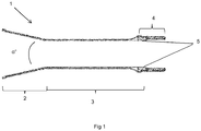
- a noise attenuation device 1 the device comprises a barrel extension portion 3.
- a tapered portion 2 which is preferably in the form of a frustrated cone.
- the tapered portion 2 is tapered such that the sides expand outwardly as a function of distance from the barrel extension portion.
- the cone angle ⁇ ° is 25°.
- the connector 4 allows the barrel extension portion 3 to be connected to an existing munition barrel, such as a mortar barrel.
- the inner surface (bore) 5 of the barrel extension portion 3, should be substantially the same bore as the munition barrel to ensuring a gas tight seal with a munition progressing up the barrel extension portion.
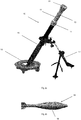
- the mortar launcher 10 comprises a barrel portion 15, which is supported by a base plate 16, which may be sunk into the ground.
- the mortar launcher 10, is further supported by a bi-pod 17, to allow the mortar launcher 10 to be arranged at a specific elevation.
- a noise reduction device 11 At the open end of the mortar barrel 15, is located a noise reduction device 11.
- the noise reduction device 11 comprises a barrel extension portion 13.
- a tapered portion 12 At a first end of the barrel extension portion 13 is a tapered portion 12, which is preferably in the form of a frustrated cone.
- the connector 14 reversibly connects the noise reduction device 11 to the open end of the barrel 15.
- a mortar bomb 18 is then deposited down the elongate barrel portion 12 and barrel 15. It is essential that the elongate barrel portion 12 and barrel 15 are of substantially the same bore, (same inner diameters) such that the mortar bomb 18 forms a gas tight seal via the obturator 19, with the inner wall of the barrel 15 and elongate barrel portion 12.
Landscapes
- Engineering & Computer Science (AREA)
- General Engineering & Computer Science (AREA)
- Percussive Tools And Related Accessories (AREA)
Abstract
This invention relates to a noise attenuation device and in particular a device which provides an increased performance in the range of a mortar system.
A noise attenuation device suitable for use on a munition barrel, said device comprising an barrel extension portion, at a first end of said barrel extension portion there is a tapered portion which tapers outwardly from said barrel extension portion, at a second end of the barrel extension portion a connector to secure the device onto a munition barrel.
Description
- This invention relates to a noise attenuation device and in particular a device which provides an increased performance in the range of a mortar system.
- Blast attenuation devices such as muzzle brakes are well known in the art. They typically provide a means of allowing the rapid dispersion of the hot gases. Further features on these device is that they use apertures, such as slits or holes to allow the gases to disperse radially outwardly, to reduce the recoil of the barrel and attached ordnance.
- In a first aspect, the present invention provides a noise attenuation device suitable for use on a munition barrel, said device comprising an barrel extension portion, at a first end of said barrel extension portion there is a tapered portion which tapers outwardly from said barrel extension portion, at a second end of the barrel extension portion a connector to secure the device onto a munition barrel.
- The tapered portion may be is frustroconical, cupola, parabola, flared portion, to allow the controlled dispersion of the gases produced as the munition leaves the barrel.
- Detailed optimised modelling has found that when the tapered portion is a frustroconical portion, has a cone angle α° in the range of 22° to 28°, highly preferably a cone angle of substantially 25°.
- Preferably the height of the tapered portion is in the range of from 5cm to 30cm, more preferably in the range of 10cm to 20 cm more preferably the height of the frustroconical portion is in the range of 10 cm to 20 cm, most preferably 13.34cm.
- The tapered portion may have sides which may be substantially straight, parabolic, curved, trumpet shaped sides, in a highly preferred arrangement the tapered portion has substantially straight sides.
- The frustroconical portion has a base. The plane of the base may be substantially perpendicular to the plane of the barrel extension portion or it may be an elliptical/parabolic conic section, or slant cut. The base may have any shaped cross section, such as for example elliptical, circular, square, highly preferably a right angled frustrated cone with a substantially circular base.
- The tapered portion comprises an inner surface and an outer surface, the inner surface may comprise a textured surface, such as for example concave convex portions, such as for example ridges, grooves, voids, such as to alter the flow of the combustion gases.
- The inner surface of the tapered portion may comprise a coating or layer, to alter the friction of the surface, such as paints, polymers etc.
- The barrel extension portion is a tube with an internal diameter (bore) substantially the same as the internal diameter(bore) as the munition barrel to which it is attached, such that the munition to be launched retains substantially the same gas tight seal in the barrel extension portion. In a preferred arrangement the barrel extension portion has a length in the range of from 10 cm to 60cm, more preferably 30 cm to 50cm, more preferably 45cm.
- The device may be manufactured from any suitable material, such as a metal, polymer, composite, preferably a metal, preferably steel. Preferably the barrel extension portion and taper are selected from the same material.
- The barrel extension portion, when deployed on the munition barrel, provides a temporary increase in overall barrel length, thereby increasing the time that the munition experiences the impulse from the hot expanding gases from the burning propellant. This may allow a reduction in the mass of propellant required to achieve the same range usually achievable with the munition's normal propellant mass. The reduction of propellant required to achieve the current maximum range, reduces the blast pressure. The combination of reduced propellant mass munition and a device according to the invention comprising a tapered portion may provide a reduction in noise to operators located around the weapon.
- The use of a device on a 81 mm standard mortar barrel in combination with an 81 mm mortar with 20% reduced propellant mass, has been demonstrated to provide a 5dB reduction in noise to operators located proximate to the device, whilst maintaining the required distance for the mortar bomb.
- Ii has been shown that a device when attached to a munition barrel allows a reduced mass propellant munition to be launched and to achieve substantially the same range.
- The connector must provide a gas tight seal between the device and the munition barrel. The connector and munition barrel may comprise co-operatively engaging surfaces, such as threads, collets, locking rings.
- The tapered portion may be reversibly attached to the barrel extension portion, such that the device may be more conveniently stored.
- According to a further aspect of the invention there is provided a munition system comprising a munition barrel, a munition capable of being launched via said barrel, and a noise attenuation device as defined herein, said attenuation device attached by a connector to said munition barrel, wherein the munition has a reduced mass of propellant. The reduction may be at least 1%wt, preferably at least 10%wt, more preferably in the range of 5 to 20%wt.
-
- Figure 1 a, b cross section of a noise reduction device, with a connector.
-
Figure 2a, 2b , show a side view of a mortar barrel with a noise reduction device attached thereto, and a mortar. - Turing to
figure 1 there is provided anoise attenuation device 1, the device comprises abarrel extension portion 3. At a first end of thebarrel extension portion 3 is atapered portion 2, which is preferably in the form of a frustrated cone. Thetapered portion 2, is tapered such that the sides expand outwardly as a function of distance from the barrel extension portion. The cone angle α° is 25°. At the second end of thebarrel extension portion 3 is aconnector 4. Theconnector 4 allows thebarrel extension portion 3 to be connected to an existing munition barrel, such as a mortar barrel. The inner surface (bore) 5 of thebarrel extension portion 3, should be substantially the same bore as the munition barrel to ensuring a gas tight seal with a munition progressing up the barrel extension portion. - Turing to
fig 2a , there is provided aL16 81mm mortar 10, which has been in service since 1965. Themortar launcher 10 comprises abarrel portion 15, which is supported by abase plate 16, which may be sunk into the ground. Themortar launcher 10, is further supported by abi-pod 17, to allow themortar launcher 10 to be arranged at a specific elevation. At the open end of themortar barrel 15, is located anoise reduction device 11. Thenoise reduction device 11 comprises abarrel extension portion 13. At a first end of thebarrel extension portion 13 is a tapered portion 12, which is preferably in the form of a frustrated cone. Theconnector 14 reversibly connects thenoise reduction device 11 to the open end of thebarrel 15. - A
mortar bomb 18 is then deposited down the elongate barrel portion 12 andbarrel 15. It is essential that the elongate barrel portion 12 andbarrel 15 are of substantially the same bore, (same inner diameters) such that themortar bomb 18 forms a gas tight seal via theobturator 19, with the inner wall of thebarrel 15 and elongate barrel portion 12.
Claims (11)
1. A noise attenuation device suitable for use on a munition barrel, said device comprising an barrel extension portion, at a first end of said barrel extension portion there is a tapered portion which tapers outwardly from said barrel extension portion, at a second end of the barrel extension portion a connector to secure the device onto a munition barrel.
2. A device according to claim 1 wherein said tapered portion, is frustroconical, cupola, parabola, flared portion.
3. A device according to claim 2, wherein the frustroconical portion has a cone angle in the range of 22° to 28°
4. A device according to claim 3, wherein the frustroconical portion has a cone angle of substantially 25°.
5. A device according to any one of the preceding claims wherein the barrel extension portion has a length in the range of 30cm to 60cm.
5. A device according to any one of claims 2 to 4, wherein the height of the frustroconical portion is in the range of 10 cm to 17 cm.
6. A device according to any one of the preceding claims wherein the device when attached to a munition barrel allows a reduced mass propellant munition to be launched and to achieve substantially the same range.
7. A device according to any one of the preceding claims wherein the connector and munition barrel comprise co-operatively engaging surfaces.
8. A device according to any one of the preceding claims wherein the tapered portion is reversibly attached to the barrel extension portion
9. A munition system comprising a munition barrel, a munition capable of being launched via said barrel, and a noise attenuation device according to any one of the preceding claims, said attenuation device attached by a connector to said munition barrel, wherein the munition has a reduced mass of propellant.
10. A system according to claim 9, wherein the reduction of propellant is in the range of 5 to 20%wt.
Priority Applications (6)
| Application Number | Priority Date | Filing Date | Title |
|---|---|---|---|
| EP16275159.8A EP3315892A1 (en) | 2016-10-28 | 2016-10-28 | Noise attenuation device |
| PCT/GB2017/053013 WO2018078320A1 (en) | 2016-10-28 | 2017-10-05 | Noise attenuation device |
| US16/345,567 US10670363B2 (en) | 2016-10-28 | 2017-10-05 | Noise attenuation device |
| LTEP17784672.2T LT3532794T (en) | 2016-10-28 | 2017-10-05 | Noise attenuation device |
| EP17784672.2A EP3532794B1 (en) | 2016-10-28 | 2017-10-05 | Noise attenuation device |
| PT177846722T PT3532794T (en) | 2016-10-28 | 2017-10-05 | Noise attenuation device |
Applications Claiming Priority (1)
| Application Number | Priority Date | Filing Date | Title |
|---|---|---|---|
| EP16275159.8A EP3315892A1 (en) | 2016-10-28 | 2016-10-28 | Noise attenuation device |
Publications (1)
| Publication Number | Publication Date |
|---|---|
| EP3315892A1 true EP3315892A1 (en) | 2018-05-02 |
Family
ID=57249759
Family Applications (1)
| Application Number | Title | Priority Date | Filing Date |
|---|---|---|---|
| EP16275159.8A Ceased EP3315892A1 (en) | 2016-10-28 | 2016-10-28 | Noise attenuation device |
Country Status (2)
| Country | Link |
|---|---|
| EP (1) | EP3315892A1 (en) |
| PT (1) | PT3532794T (en) |
Citations (3)
| Publication number | Priority date | Publication date | Assignee | Title |
|---|---|---|---|---|
| NL6804528A (en) * | 1967-04-01 | 1968-10-02 | ||
| US6308608B1 (en) * | 1998-08-30 | 2001-10-30 | Moshe Eisenman | Dust suppression |
| EP1956335A2 (en) * | 2007-02-08 | 2008-08-13 | Honeywell International Inc. | Velocity measurement using manetoresistive sensors |
-
2016
- 2016-10-28 EP EP16275159.8A patent/EP3315892A1/en not_active Ceased
-
2017
- 2017-10-05 PT PT177846722T patent/PT3532794T/en unknown
Patent Citations (3)
| Publication number | Priority date | Publication date | Assignee | Title |
|---|---|---|---|---|
| NL6804528A (en) * | 1967-04-01 | 1968-10-02 | ||
| US6308608B1 (en) * | 1998-08-30 | 2001-10-30 | Moshe Eisenman | Dust suppression |
| EP1956335A2 (en) * | 2007-02-08 | 2008-08-13 | Honeywell International Inc. | Velocity measurement using manetoresistive sensors |
Also Published As
| Publication number | Publication date |
|---|---|
| PT3532794T (en) | 2021-02-02 |
Similar Documents
| Publication | Publication Date | Title |
|---|---|---|
| US9903678B2 (en) | Method of manufacturing a diffuser muzzle brake | |
| US9423198B1 (en) | Flash hider with gas flow control modules and associated methods | |
| US8418803B2 (en) | Flash suppressor | |
| US8166861B2 (en) | Shock reduction muzzle brake | |
| US10274278B2 (en) | Firearm attachment | |
| US11428490B2 (en) | Inaudible frequency suppressor | |
| US10234229B2 (en) | Muzzle end accessory mount for a firearm | |
| US20190041155A1 (en) | Muzzle Device | |
| US9976830B2 (en) | Firearm barrel including a gas pressure relief chamber | |
| EP3171119B1 (en) | Firearm suppressor and method of operation | |
| US9417022B2 (en) | Combination flash hider and muzzle brake | |
| EP2965033A1 (en) | Silencer for a firearm | |
| US9163892B1 (en) | Muzzle break with supersonic nozzle | |
| US20180238652A1 (en) | Firearm Barrel Including a Gas Pressure Relief Chamber | |
| EP3532794B1 (en) | Noise attenuation device | |
| EP3382318A1 (en) | Silencer for a shotgun | |
| US10508879B1 (en) | Device for dampening residual effects from a firearm suppressor | |
| CN101970972B (en) | Apparatus, support member and method for supporting projectiles entering a barrel of a weapon | |
| US8550002B2 (en) | Arrangement for supporting mortar shell into breech-loading weapon barrel | |
| GB2555579A (en) | Noise attenuation device | |
| US8091263B1 (en) | Reduced recoil choked shotgun barrel | |
| US20210278159A1 (en) | Firearm Barrel Including a Gas Pressure Relief Chamber | |
| US8458945B2 (en) | One piece progressive bore multi-staged shotgun choke system | |
| US20180010874A1 (en) | Firearm flash hider | |
| CN209559016U (en) | A kind of silencer that using effect is good |
Legal Events
| Date | Code | Title | Description |
|---|---|---|---|
| PUAI | Public reference made under article 153(3) epc to a published international application that has entered the european phase |
Free format text: ORIGINAL CODE: 0009012 |
|
| AK | Designated contracting states |
Kind code of ref document: A1 Designated state(s): AL AT BE BG CH CY CZ DE DK EE ES FI FR GB GR HR HU IE IS IT LI LT LU LV MC MK MT NL NO PL PT RO RS SE SI SK SM TR |
|
| AX | Request for extension of the european patent |
Extension state: BA ME |
|
| 18R | Application refused |
Effective date: 20180521 |