EP3315885A1 - Home appliance device - Google Patents
Home appliance device Download PDFInfo
- Publication number
- EP3315885A1 EP3315885A1 EP17195278.1A EP17195278A EP3315885A1 EP 3315885 A1 EP3315885 A1 EP 3315885A1 EP 17195278 A EP17195278 A EP 17195278A EP 3315885 A1 EP3315885 A1 EP 3315885A1
- Authority
- EP
- European Patent Office
- Prior art keywords
- cover element
- home appliance
- guiding
- appliance device
- cover
- Prior art date
- Legal status (The legal status is an assumption and is not a legal conclusion. Google has not performed a legal analysis and makes no representation as to the accuracy of the status listed.)
- Granted
Links
Images




Classifications
-
- F—MECHANICAL ENGINEERING; LIGHTING; HEATING; WEAPONS; BLASTING
- F25—REFRIGERATION OR COOLING; COMBINED HEATING AND REFRIGERATION SYSTEMS; HEAT PUMP SYSTEMS; MANUFACTURE OR STORAGE OF ICE; LIQUEFACTION SOLIDIFICATION OF GASES
- F25D—REFRIGERATORS; COLD ROOMS; ICE-BOXES; COOLING OR FREEZING APPARATUS NOT OTHERWISE PROVIDED FOR
- F25D25/00—Charging, supporting, and discharging the articles to be cooled
- F25D25/02—Charging, supporting, and discharging the articles to be cooled by shelves
- F25D25/024—Slidable shelves
-
- A—HUMAN NECESSITIES
- A47—FURNITURE; DOMESTIC ARTICLES OR APPLIANCES; COFFEE MILLS; SPICE MILLS; SUCTION CLEANERS IN GENERAL
- A47B—TABLES; DESKS; OFFICE FURNITURE; CABINETS; DRAWERS; GENERAL DETAILS OF FURNITURE
- A47B96/00—Details of cabinets, racks or shelf units not covered by a single one of groups A47B43/00 - A47B95/00; General details of furniture
- A47B96/02—Shelves
- A47B96/025—Shelves with moving elements, e.g. movable extensions or link elements
-
- F—MECHANICAL ENGINEERING; LIGHTING; HEATING; WEAPONS; BLASTING
- F16—ENGINEERING ELEMENTS AND UNITS; GENERAL MEASURES FOR PRODUCING AND MAINTAINING EFFECTIVE FUNCTIONING OF MACHINES OR INSTALLATIONS; THERMAL INSULATION IN GENERAL
- F16C—SHAFTS; FLEXIBLE SHAFTS; ELEMENTS OR CRANKSHAFT MECHANISMS; ROTARY BODIES OTHER THAN GEARING ELEMENTS; BEARINGS
- F16C29/00—Bearings for parts moving only linearly
- F16C29/04—Ball or roller bearings
- F16C29/045—Ball or roller bearings having rolling elements journaled in one of the moving parts
-
- F—MECHANICAL ENGINEERING; LIGHTING; HEATING; WEAPONS; BLASTING
- F16—ENGINEERING ELEMENTS AND UNITS; GENERAL MEASURES FOR PRODUCING AND MAINTAINING EFFECTIVE FUNCTIONING OF MACHINES OR INSTALLATIONS; THERMAL INSULATION IN GENERAL
- F16C—SHAFTS; FLEXIBLE SHAFTS; ELEMENTS OR CRANKSHAFT MECHANISMS; ROTARY BODIES OTHER THAN GEARING ELEMENTS; BEARINGS
- F16C29/00—Bearings for parts moving only linearly
- F16C29/04—Ball or roller bearings
- F16C29/048—Ball or roller bearings with thin walled races, e.g. tracks of sheet metal
-
- F—MECHANICAL ENGINEERING; LIGHTING; HEATING; WEAPONS; BLASTING
- F16—ENGINEERING ELEMENTS AND UNITS; GENERAL MEASURES FOR PRODUCING AND MAINTAINING EFFECTIVE FUNCTIONING OF MACHINES OR INSTALLATIONS; THERMAL INSULATION IN GENERAL
- F16C—SHAFTS; FLEXIBLE SHAFTS; ELEMENTS OR CRANKSHAFT MECHANISMS; ROTARY BODIES OTHER THAN GEARING ELEMENTS; BEARINGS
- F16C29/00—Bearings for parts moving only linearly
- F16C29/08—Arrangements for covering or protecting the ways
- F16C29/082—Arrangements for covering or protecting the ways fixed to the way
-
- F—MECHANICAL ENGINEERING; LIGHTING; HEATING; WEAPONS; BLASTING
- F16—ENGINEERING ELEMENTS AND UNITS; GENERAL MEASURES FOR PRODUCING AND MAINTAINING EFFECTIVE FUNCTIONING OF MACHINES OR INSTALLATIONS; THERMAL INSULATION IN GENERAL
- F16C—SHAFTS; FLEXIBLE SHAFTS; ELEMENTS OR CRANKSHAFT MECHANISMS; ROTARY BODIES OTHER THAN GEARING ELEMENTS; BEARINGS
- F16C29/00—Bearings for parts moving only linearly
- F16C29/08—Arrangements for covering or protecting the ways
- F16C29/084—Arrangements for covering or protecting the ways fixed to the carriage or bearing body movable along the guide rail or track
-
- F—MECHANICAL ENGINEERING; LIGHTING; HEATING; WEAPONS; BLASTING
- F25—REFRIGERATION OR COOLING; COMBINED HEATING AND REFRIGERATION SYSTEMS; HEAT PUMP SYSTEMS; MANUFACTURE OR STORAGE OF ICE; LIQUEFACTION SOLIDIFICATION OF GASES
- F25D—REFRIGERATORS; COLD ROOMS; ICE-BOXES; COOLING OR FREEZING APPARATUS NOT OTHERWISE PROVIDED FOR
- F25D11/00—Self-contained movable devices, e.g. domestic refrigerators
-
- F—MECHANICAL ENGINEERING; LIGHTING; HEATING; WEAPONS; BLASTING
- F16—ENGINEERING ELEMENTS AND UNITS; GENERAL MEASURES FOR PRODUCING AND MAINTAINING EFFECTIVE FUNCTIONING OF MACHINES OR INSTALLATIONS; THERMAL INSULATION IN GENERAL
- F16C—SHAFTS; FLEXIBLE SHAFTS; ELEMENTS OR CRANKSHAFT MECHANISMS; ROTARY BODIES OTHER THAN GEARING ELEMENTS; BEARINGS
- F16C2362/00—Apparatus for lighting or heating
- F16C2362/52—Compressors of refrigerators, e.g. air-conditioners
-
- F—MECHANICAL ENGINEERING; LIGHTING; HEATING; WEAPONS; BLASTING
- F25—REFRIGERATION OR COOLING; COMBINED HEATING AND REFRIGERATION SYSTEMS; HEAT PUMP SYSTEMS; MANUFACTURE OR STORAGE OF ICE; LIQUEFACTION SOLIDIFICATION OF GASES
- F25D—REFRIGERATORS; COLD ROOMS; ICE-BOXES; COOLING OR FREEZING APPARATUS NOT OTHERWISE PROVIDED FOR
- F25D23/00—General constructional features
- F25D23/06—Walls
- F25D23/065—Details
- F25D23/067—Supporting elements
Definitions
- the invention relates to a home appliance device, in particular a home appliance chiller device, according to claim 1.
- US 8,490428 A1 discloses a refrigerator and/or freezer which comprises telescopic guiding units and which has a stationary guiding element. Further, a cover element is disclosed which partly covers the stationary guiding element.
- One object of the invention is, in particular, to provide a generic home appliance device with improved characteristics regarding protection. This object is achieved, according to the invention, by the features of claim 1, while advantageous implementations and further developments of the invention may be gathered from the dependent claims.
- a home appliance device in particular a home appliance chiller device, comprising: a telescopic guiding unit, which is convertible at least from a fully contracted state to a fully extracted state and vice versa and which has at least one stationary guiding element; and comprising a cover unit, which at least mostly covers the stationary guiding element at least in the fully extracted state.
- the guiding unit may serve as a visual cover which hides the stationary guiding element from view.
- the cover unit protects the guiding unit from debris and condensed water, which could in particular cause corrosion and/or jamming of the guiding unit, cleanliness as well as a lifetime of the home appliance device may be increased.
- an operating safety may be improved, in particular as the cover unit prevents a user's limbs from getting caught in the guiding unit.
- a “configured” is in particular to mean specifically programmed, designed and/or equipped.
- an object being configured for a certain function is in particular to be understood that the object implements and/or fulfills said certain function in at least one application state and/or operating state.
- a “home appliance device” is in particular to be understood at least a portion, preferably a sub-assembly group, of a home appliance.
- the home appliance is in particular provided for storing and preferably tempering victuals such as beverages, in particular alcoholic beverages such as wine, meat, fish, vegetables, fruits, milk and/or dairy products in at least one operating state, advantageously for the purpose of enhancing a quality and/or a keepability of the stored victuals.
- the home appliance may be embodied as a home chiller appliance, which is in at least one operating state configured for cooling victuals.
- the home chiller appliance may in particular be embodied as a climate cabinet, an ice-box, a refrigerator, a freezer and/or a refrigerator-freezer combination.
- the home chiller appliance may be embodied as a wine cooler.
- the home appliance may also be embodied as a home appliance for warming up and in particular for cooking victuals, e.g. an oven, a steamer and/or a microwave.
- the home appliance device may in particular further comprise an insert and preferably an inner liner.
- the guiding unit is in particular configured for extraction and/or contraction of the insert out of and/or into the inner liner.
- the guiding unit may in particular be fixable, or detachably fixable, in the fully extracted state and/or the fully contracted state.
- the guiding unit may be configured for allowing a sliding motion of the insert with respect to the inner liner.
- the stationary guiding element of the guiding unit stays in place and may be coupled to the inner liner.
- “coupled” is in particular to mean at least indirectly or directly attached, fixed and/or connected.
- a main extension of the guiding unit is longer than a main extension of the guiding unit in the fully contracted state, in particular by at least 50 %, or at least 65 %, or at least 80 % or at least 95 % than a main extension of the guiding unit in the fully contracted state.
- a "main extension" of an object is, in particular, to be understood, in this context, as a longest side of an imaginary rectangular cuboid which only just entirely encloses the object.
- “convertible” is in particular to mean extractable, in particular repeatably extractable, or in an extraction direction, or in addition contractible in a contraction direction.
- the extraction direction and the contraction direction may be in particular antiparallel directions and extend in particular at least substantially parallel to the main extension of the guiding unit or in addition at least substantially parallel to a horizontal plane of the home appliance device, advantageously regardless of the state of the guiding unit.
- a "horizontal plane” is in particular to be understood as a main extension plane of a base onto which the home appliance device is installed in an installation position.
- a "main extension plane” of an object is, in particular, to be understood as a plane extending parallel to a largest side of an imaginary rectangular cuboid which only just entirely encloses the object or in addition extends through a geometric center of the object.
- At least substantially parallel is in particular to be understood as an orientation of a direction with respect to a reference direction, in particular in a plane, wherein the direction and the reference direction include an angle of 0°, the orientation in particular having a deviation of less than 15°, or of less than 10° or of less than 2°.
- the insert is in particular configured for storage of victuals.
- the insert may in particular be implemented as a shelf, or an at least partly transparent shelf, e.g. made of glass and/or of a transparent plastic, as a cover for a drawer, which is in particular configured for adjusting humidity in the drawer, and/or as a dividing plate, which in an installation position may divide a storage space into at least two storage areas.
- the insert may be implemented as a bottle holder.
- a "bottle holder" is in particular to be understood as a shelf which is configured for depositing bottles.
- the insert comprises a frame and at least two elongate deposit elements, which are fixed to the frame and are arranged offset to each other in a direction at least substantially perpendicular to a main extension direction of the deposit elements.
- at least two deposit elements may be configured for storage of at least one bottle.
- at least substantially perpendicular is in particular to be understood as an orientation of a direction with respect to a reference direction, in particular in a plane, wherein the direction and the reference direction form an angle of 90° and in particular having a deviation of less than 15°, or of less than 10° or of less than 2°.
- the deposit elements may be implemented as slats and/or rods.
- the deposit elements are made of wood.
- the insert may comprise a profile which is at least partly shaped corresponding to a contour of a bottle.
- the cover unit may be in particular implemented separate from the guiding unit.
- the cover unit may be at least partly implemented integrally with the inner liner and/or the insert.
- the term "a first object and a second object being at least partly implemented integrally” is in particular to mean that at least one component of the first object and at least one component of the second object are implemented integrally with each other.
- “Implemented integrally” is in particular to mean, in this context, connected at least by substance-to-substance bond, e.g. by a welding process, an adhesive bonding, an injection-molding process and/or by another process that is deemed expedient by a person having ordinary skill in the art.
- "implemented integrally” could in particular mean made of one piece.
- Melt of one piece is, in particular, to mean, in this context, manufactured from one single piece, e.g. by production from one single cast and/or by manufacturing in a one-component or multi-component injection-molding process, or from a single blank.
- a first object at least partly covering a second object is in particular to mean that the first object covers and/or encloses the second object from at least one side, or from at least two sides, or from at least three sides or from at least four sides.
- the second object, or a surface area of the second object is at least partly arranged or hidden behind the first object, wherein in particular the surface area has a normal vector which is at least substantially parallel to the viewing direction.
- the cover unit at least mostly covers the stationary guiding element in the fully extracted state.
- the term "at least mostly” with reference to an object is in particular to mean by more than 50 %, or more than 65 %, or more than 80 % or more than 95 % of an object, in particular a surface area, ora volume and/or a mass of the object.
- the cover unit may comprise a first cover element and a second cover element, which are movably coupled to each other by the guiding unit, in particular in a direction at least substantially parallel to the extraction and/or contraction direction.
- a first object and a second object being movably coupled is in particular to mean that the first object and the second object are at least indirectly attached, connected and/or fixed to each other and movable with respect to each other or in addition in at least one direction, or in precisely one direction.
- the first cover element is in particular implemented as a stationary cover element.
- the first cover element is in particular coupled to the inner liner.
- the second cover element is in particular implemented as a movable cover element, which is in particular movable with respect to the first cover element.
- first cover element and the second cover element For the purpose of effectively arranging the first cover element and the second cover element in the contracted state in such a way that a construction-space can be reduced, it is proposed that the first cover element and the second cover element at least partly, or at least mostly or entirely, overlap in the fully contracted state, in particular viewed in a direction at least substantially perpendicular to the extraction and/or contraction direction.
- the term "a first object and a second object at least partly overlapping" is in particular to mean that the objects cover each other at least partly, and that they extend at least partly, or at least mostly and or entirely, at least substantially parallel to each other.
- first cover element and the second cover element are arranged consecutively.
- first cover element and the second cover element may at least partly, or at most minorly overlap in the fully extracted state, in particular viewed in a direction at least substantially perpendicular to the extraction direction and/or the contraction direction.
- the term "at most minorly" with reference to an object is in particular to mean by less than 50 %, or less than 35%, or less than 20 % or less than 5 % of the object, in particular of a surface area, of a volume and/or of a mass of the object.
- a cleanliness of the cover unit can be improved as debris and condensed water can be prevented from entering between the first cover element and the second cover element.
- an effective arrangement of the first cover element and the second cover element, in particular in the fully extracted state of the guiding unit can be achieved such that no additional material is required, which reduces costs.
- the second cover element may at least partly enclose the first cover element from at least one side, in particular a first side, a second side, a third side and/or a fourth side, at least in the fully contracted state and in particular in the fully contracted state.
- a first object being enclosed by a second object from at least one side is in particular to mean that the first object is at least partly surrounded or closed off by the second object from the at least one side.
- a straight line which originates in the second object and which is in particular at least substantially parallel to the side and/orconsecutively crosses the first object and then extends into the second object.
- a "side” is in particular to be understood as a spatial plane which extends at least substantially parallel the extraction direction and/or the contraction direction.
- the first side is in particular at least substantially parallel to the horizontal plane.
- the second side is in particular at least perpendicular to the horizontal plane.
- the third side is in particular at least substantially parallel to the horizontal plane.
- the fourth side is in particular at least substantially perpendicular to the horizontal plane.
- the first side and the third side are in particular opposite sides.
- the second side and the fourth side are in particular opposite sides.
- the second cover element at least partly engages into the first cover element from at least one side, in particular the first side, the second side, the third side and/or the fourth side, in the fully contracted state.
- the second cover element engages into the first cover element in particular from the same side from which the first cover element is at least partly enclosed by the second cover element.
- the term "a first object at least partly engaging into a second object from at least one side” is in particular to mean that the second object delimits a receiving region into which the first object at least partly extends, in particular in a direction at least substantially perpendicular to the side from which the first object extends into the second object.
- the first cover element and the second cover element together at least mostly cover the guiding unit from at least one side, in particular the first side, the second side, the third side and/or the fourth side, in the fully extracted state.
- the first cover element and the second cover element together at least mostly cover the guiding unit from the same side from which the first cover element is also at least partly enclosed by the second cover element.
- the first cover element encloses the guiding unit from at least three sides, in particular the first side, the second side, the third side and/or the fourth side, viewed along the extraction direction of the guiding unit.
- the guiding unit can in particular be protected at least partly by the first cover element.
- the first cover element may have a cross-section which is at least substantially spiral-shaped, in particular viewed along the extraction direction.
- an "at least substantially spiral-shaped object” is to be understood as an object which revolves around a center point at least section-wise, in particular in straight consecutive sections that include angles with each other, and which may converge into the center point, wherein the center point is in particular a geometric center point of the object.
- consecutive sections include an angle of more than 0°, or more than 30°, or more than 60°, and/or in particular less than 180°, or less than 150°, or at most 120°.
- consecutive sections are arranged at least substantially perpendicular to each other.
- the at least substantially spiral-shaped object comprises in particular at least four, or at least five, or precisely five, consecutive sections. In this way, the first cover element can be implemented in a simple manner.
- the first cover element has a cross-section which is at least substantially u-shaped, in particular viewed along the extraction direction.
- an "at least substantially u-shaped object” is to be understood as an object which revolves around a center point at least section-wise, in particular in straight consecutive sections that include angles with each other, wherein the center point is in particular a geometric center point of the object.
- consecutive sections include angles of more than 0°, or more than 30°, or more than 60°, and/or less than 180°, or less than 150°, or at most 120°.
- consecutive sections may be arranged at least substantially perpendicular to each other.
- the at least substantially u-shaped object comprises in particular at least three, or precisely three, consecutive sections of this kind. In this way, the first cover element can be implemented in a simple manner.
- the second cover element encloses the guiding unit from at least one side, in particular the first side, the second side, the third side and/or the fourth side, viewed along an extraction direction of the guiding unit.
- the second cover element has a cross-section which is at least partly at least substantially u-shaped, in particular viewed along the extraction direction.
- the guiding unit can in particular be protected at least partly by the second cover element.
- the guiding unit comprises at least one movable guiding element, which is movably coupled to the stationary guiding element, wherein the first cover element is coupled to the stationary guiding element and the second cover element is coupled to the movable guiding element.
- the first cover element may in particular be fixed to the stationary guiding element in a force-fit and/or form-fit manner.
- the second cover element may in particular be fixed to the movable guiding element in a force-fit and/or form-fit manner.
- the guiding unit may comprise in particular at least one further movable guiding element, which may couple the movable guiding element to the stationary guiding element.
- the further movable guiding element may be in particular arranged at least partly between the stationary guiding element and the movable guiding element.
- the movable guiding element and the stationary guiding element may be coupled to each other directly.
- the guiding elements may be in particular implemented as guiding rails. It is conceivable that the first cover element may be coupled to the movable guiding element and that the second cover element may be coupled to the stationary guiding element. As a result, a movement of the guiding unit may be transferred to the cover unit such that the cover unit protects the guiding unit in each state.
- first cover element may be configured for coupling with an inner liner, in particular the before-mentioned inner liner
- second cover element may be configured for coupling with the insert, in particular the before-mentioned insert.
- first cover element may be fixed to the inner liner in a force-fit and/or form-fit manner.
- first cover element may be at least partly integrally implemented with the inner liner, or in addtion with a lateral wall of the inner liner.
- the second cover element may be in particular coupled to the insert.
- the second cover element may be fixed to the insert in a force-fit and/or form-fit manner.
- first cover element may be at least partly implemented integrally with the insert,in particular with the frame of the insert.
- first cover element may be configured for coupling with the inner liner and the second cover element may be configured for coupling with the insert.
- the guiding unit may move the insert into and out of the inner liner while being continuously protected by the cover unit.
- the first cover element may in particular comprise a first wall section, by means of which the first cover element is configured to be coupled to the inner liner, and by means of which the first cover element is coupled to the guiding unit, wherein in particular the inner liner and the guiding unit are attached to sides of the first wall section which face in opposite directions.
- the first cover element may have a first wall section, by means of which the first cover element may be configured to be coupled to the inner liner, and has a second wall section, by means of which the first cover element may be coupled to the guiding unit, wherein the first wall section and the second wall section are arranged opposite each other.
- the inner liner and the guiding unit may be in particular attached to sides of the first wall section, respectively the second wall section, which face in the same direction.
- the home appliance device comprises an insert, in particular the before-mentioned insert, which may be embodied as a bottle holder and may be coupled to the guiding unit.
- the home appliance device may be not to be limited to the application and implementation described above.
- the home appliance device may comprise a number of respective elements, structural components and units that differs from the number mentioned herein.
- values within the limits mentioned are to be understood to be also disclosed and to be used as applicable.
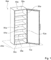
- Fig. 1 shows a home appliance 45a comprising a home appliance device, in a schematic perspective view.
- the home appliance 45a is embodied as a wine cooler.
- the home appliance 45a could further be embodied as a refrigerator, a climate cabinet, an ice-box, a freezer and/or a refrigerator-freezer combination.
- the home appliance device is shown in an installation position.
- the home appliance device is installed on a base.
- the base defines a horizontal plane 46a.
- the home appliance device comprises a housing 48a.
- the housing 48a is installed upright on the base.
- the home appliance device comprises an inner liner 36a.
- the inner liner 36a is arranged inside the housing 48a.
- the inner liner 36a defines a storage space 50a.
- the inner liner 36a comprises walls 52a, 54a, 56a, 58a, which delimit the storage space 50a.
- the inner liner 36a has two lateral walls 52a, or in addition opposite each other.
- the inner liner 36a has a rear wall 54a.
- the inner liner 36a has a bottom wall 56a.
- the inner liner 36a has a top wall 58a, or in addition opposite the bottom wall 56a.
- the home appliance device comprises at least one insert 38a.
- the home appliance device comprises six inserts 38a. It is conceivable that the home appliance device may comprise a deviating number of inserts 38a as deemed advantageous by someone skilled in the art.
- the insert 38a is embodied as a bottle holder.
- the home appliance device may comprise a combination of different embodiments of inserts, for example at least one insert embodied as a shelf and at least one further insert embodied as a bottle holder.
- only one insert 38a is given a reference numeral and is described in detail. The following description may be transferred to further inserts accordingly.
- the insert 38a is configured for depositing bottles.
- the insert 38a comprises a frame 60a.
- the insert 38a comprises at least two elongate deposit elements 62a.
- the deposit elements 62a are fixed to the frame 60a.
- the deposit elements 62a are arranged offset to each other in a direction at least substantially perpendicular to a main extension direction of the deposit elements 62a.
- the deposit elements 62a are implemented as slats and/or rods.
- the deposit elements 62a are made of wood.
- the insert 38a may comprise a profile which is at least partly shaped corresponding to a contour of a bottle.
- the insert 38a is coupled to a guiding unit 10a of the home appliance device.
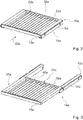
- Fig. 2 shows a portion of the home appliance device comprising the guiding unit 10a.
- the home appliance device comprises at least two guiding units 10a, in particular for each insert 38a.
- the home appliance device comprises one guiding unit 10a for each lateral wall 52a of the inner liner 36a and/or for each lateral side of the insert 38a.
- the guiding unit 10a is a telescopic guiding unit.
- the guiding unit 10a is configured for extraction and/or contraction of the insert 38a out of and/or into the inner liner 36a.
- the guiding unit 10a is convertible at least from a fully contracted state to a fully extracted state and vice versa.
- fig. 2 the guiding unit 10a is shown in the fully contracted state.
- fig. 3 the guiding unit 10a is shown in the fully extracted state.
- the guiding unit 10a may be mechanically fixable in the fully extracted state and/or the fully contracted state.
- the insert 38a is slidable between the fully contracted ad the fully extracted states by means of the guiding unit 10a.
- the guiding unit 10a is extractable in an extraction direction 28a.
- the extraction direction 28a is at least substantially parallel to a main extension of the guiding unit 10a and in particular at least substantially parallel to the horizontal plane 46a.
- the guiding unit 10a is contractible in a contraction direction 29a.
- the extraction direction 28a and the contraction direction 29a are antiparallel directions.
- a main extension of the guiding unit 10a in the fully extracted state is longer than a main extension of the guiding unit 10a in the fully contracted state.
- the main extension of the guiding unit 10a in the fully extracted state is by at least 95 % longer than the main extension of the guiding unit 10a in the fully contracted state.
- the guiding unit 10a has at least one stationary guiding element 12a.
- the stationary guiding element 12a is indirectly coupled to the inner liner 36a.
- the guiding unit 10a comprises at least one movable guiding element 32a.
- the movable guiding element 32a is indirectly coupled to the insert.
- the movable guiding element 32a is movably coupled to the stationary guiding element 12a.
- the movable guiding element 32a is movable with respect to the stationary guiding element 12a.
- the guiding unit 10a comprises at least one further movable guiding element 34a.
- the further movable guiding element 34a couples the movable guiding element 32a to the stationary guiding element 12a.
- the further movable guiding element 34a is arranged at least partly between the stationary guiding element 12a and the movable guiding element 32a.
- the guiding elements 12a, 32a, 34a are supported movably with respect to each other by bearing elements 70a.
- the bearing elements 70a may be implemented as ball bearings.
- the movable guiding element 32a and the stationary guiding element 12a may in particular be coupled to each other directly. It is conceivable that the home appliance device may comprise a deviating number of guiding elements 12a, 32a, 34a as deemed advantageous by someone skilled in the art.
- the home appliance device comprises at least one cover unit 14a.
- the home appliance device comprises at least two cover units 14a, in particular one for each guiding unit 10a.
- cover unit 14a is given a reference numeral and is described in detail. The following description can be transferred to further cover units accordingly.
- the cover unit 14a at least mostly covers the stationary guiding element 12a at least in the fully extracted state.
- the cover unit 14a comprises a first cover element 16a.
- the first cover element 16a is coupled with the inner liner 36a.
- the first cover element 16a comprises a first wall section 40a. By means of the first wall section 40a, the first cover element 16a is coupled to the inner liner 36a.
- the first cover element 16a is connected to the lateral wall 52a of the inner liner 36a in a force-fit and/or form-fit manner.
- the first cover element 16a may be implemented integrally with the inner liner 36a, in particular with the lateral wall 52a.
- the first cover element 16a is coupled to the guiding unit 10a, preferably to the stationary guiding element 12a.
- the first cover element 16a comprises a second wall section 42a.
- the first cover element 16a is coupled to the guiding unit 10a.
- the first wall section 40a and the second wall section 42a are arranged opposite each other.
- the first cover element 16a may be coupled to the inner liner 36a and the guiding unit 10a by means of only one wall section, in particular the first wall section 40a.
- the first cover element 16a covers and/or encloses the guiding unit 10a, in particular the stationary guiding element 12a at least in the fully extracted state, from at least three sides 22a, 24a, 26a, namely a first side 22a, a second side 24a, and a third side 26a (see fig. 6 ).
- the first side 22a is at least substantially perpendicular to the horizontal plane 46a.
- the second side 24a is at least substantially parallel to the horizontal plane 46a.
- the third side 26a is at least substantially perpendicular to the horizontal plane 46a.
- the first side 22a and the third side 26a are situated opposite each other.
- the first cover element 16a may enclose the guiding unit 10a, in particular the stationary guiding element 12a at least in the fully extracted state, from four sides 20a, 22a, 24a, 26a.
- the fourth side 20a would in particular be at least substantially parallel to the horizontal plane 46a.
- the second side 24a and the fourth side 20a would in particular be situated opposite each other.
- the first cover element 16a has a cross-section which is at least substantially spiral-shaped.
- the first cover element 16a comprises five consecutive wall sections 40a, 41 a, 42a, 43a, 44a.
- the consecutive wall sections 40a, 41 a, 42a, 43a, 44a are straight.
- the consecutive wall sections 40a, 41 a, 42a, 43a, 44a are connected to each other. Respectively two consecutive wall sections 40a, 41 a, 42a, 43a, 44a include an angle of 90°.
- the consecutive wall sections 40a, 41 a, 42a, 43a, 44a converge into a center point.
- the center point is the geometric center point of the first cover element 16a.
- Fig. 5 shows a portion of the cover unit 14a which comprises a second cover element 18a in a perspective view.
- the second cover element 18a and the first cover element 16a are movably coupled to each other by means of the guiding unit 10a (see fig. 6 ).
- the second cover element 18a is configured for coupling with the insert 38a.
- the second cover element 18a has a first wall section 66a. By means of the first wall section 66a, the second cover element 18a is coupled to the insert 38a. Alternatively the second cover element 18a may be integrally implemented with the insert 38a.
- the second cover element 18a is coupled to the movable guiding element 32a.
- the second cover element 18a has a second wall section 64a.
- the second cover element 18a is coupled to the guiding unit 10a, in particular to the movable guiding element 32a.
- the first wall section 66a and the second wall section 64a of the second cover element 18a are arranged opposite each other.
- the second cover element 18a encloses the guiding unit 10a from at least one side 20a. Additionally or alternatively the first cover element 16a may enclose the guiding unit 10a from three sides 20a, 22a, 26a.
- the second cover element 18a has a cross-section which is at least substantially u-shaped.
- the second cover element 18a comprises three consecutive wall sections 64a, 65a, 66a.
- the consecutive wall sections 64a, 65a, 66a are straight.
- the consecutive wall sections 64a, 65a, 66a are connected to each other. Respectively two consecutive wall sections 64a, 65a, 66a include an angle of 90°.
- the second cover element 18a at least partly engages into the first cover element 16a from at least one side 20a at least in the fully contracted state.
- the first cover element 16a delimits a receiving region 68a into which the second cover element 18a at least partly extends.
- the receiving region 68a is delimited at least by the wall sections 40a and 44a of the first cover element 16a.
- the second wall section 64a of the second cover element 18a extends into the receiving region 68a. Viewed in the extraction direction 28a, the second wall section 64a of the second cover element 18a is arranged in between the wall sections 40a, 44a of the first cover element 16a.
- the first cover element 16a and the second cover element 18a at least mostly overlap in the fully contracted state (see fig. 2 ). Viewed at least substantially perpendicular to the extraction direction 28a, the first cover element 16a and the second cover element 18a at most minorly overlap in the fully extracted state (see fig. 3 ).
- the wall section 64a of the second cover element 18a overlaps with the wall section 44a of the first cover element 16a.
- the wall section 65a of the second cover element 18a overlaps with the wall section 43a of the first cover element.
- the wall section 66a of the second cover element 18a overlaps with the wall section 42a of the first cover element 16a.
- the first cover element 16a and the second cover element 18a together at least mostly cover the guiding unit 10a from the first side 20a.
- Figs. 7 to 10 show further exemplary embodiments of the invention.
- the following description is substantially limited to the differences between the exemplary embodiments, wherein regarding structural elements, features and functions that remain the same the description of the other exemplary embodiments, in particular the exemplary embodiment of figs. 1 to 6 , may be referred to.
- the letter a of the reference numerals in the exemplary embodiment of figs. 1 to 6 has been substituted by the letters b to e in the reference numerals of the exemplary embodiments of figs. 7 to 10 .
- structural elements having the same denomination in particular regarding structural elements having the same reference numerals, principally the drawing and/or the description of the other exemplary embodiments, in particular of the exemplary embodiment of figs. 1 to 6 , may be referred to.
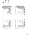
- Figs. 7 to 9 show a portion of a further home appliance device comprising a cover unit 14b-d.
- the exemplary embodiments of figs. 7 to 9 differ from the preceding exemplary embodiment at least substantially by their respective implementations of a first cover element 16b-d and a second cover element 18b-d.
- the different implementations may in particular be transferred into each other by reflections across the marked axis.
- the properties of the first cover element and the second cover element are swapped, such that the second cover element may be configured to be coupled to an inner liner, while the first cover element is configured to be coupled to an insert.
- the first cover element 16b-d may be configured to be coupled to a movable guiding element, while the second cover element 18b-d may be configured to be coupled to a stationary guiding element.
- Fig. 10 shows a portion of another exemplary embodiment of a home appliance device, comprising a cover unit 14e.
- the cover unit 14e at least mostly covers a stationary guiding element 12e at least in the fully extracted state.
- a first cover element 16e covers and/or encloses a guiding unit 10e, in particular the stationary guiding element 12a, at least in the fully extracted state, from at least three sides 22e, 24e, 26e, namely a first side 22e, a second side 24e, and a third side 26e (see fig. 6 ).
- the first side 22e is at least substantially perpendicular to the horizontal plane 46e.
- the second side 24e is at least substantially parallel to a horizontal plane 46e.
- the third side 26e is at least substantially perpendicular to the horizontal plane 46e.
- the first side 22e and the third side 26e are situated opposite each other.
- the first cover element 16e has a cross-section which is at least substantially u-shaped.
- the first cover element 16e comprises three consecutive wall sections 40e, 41 e, 42e.
- the consecutive wall sections 40e, 41 e, 42e are straight.
- the consecutive wall sections 40e, 41 e, 42e are connected to each other.
- Respectively two consecutive wall sections 40e, 41 e, 42e include an angle of 90°.
- a second cover element 18e at least partly engages into the first cover element 16e from at least one side 20e, in particular a fourth side 20e, at least in the fully contracted state.
- the first cover element 16e delimits a receiving region 68e into which the second cover element 18e at least partly extends.
- the receiving region 68e is delimited at least by the wall sections 40e and 42e of the first cover element 16e.
- a second wall section 64e of the second cover element 18e extends into the receiving region 68e. Viewed in the extraction direction 28e, the second wall section 64e of the second cover element 18e is arranged in between the wall sections 40e, 42e of the first cover element 16a.
Landscapes
- Engineering & Computer Science (AREA)
- General Engineering & Computer Science (AREA)
- Mechanical Engineering (AREA)
- Chemical & Material Sciences (AREA)
- Combustion & Propulsion (AREA)
- Physics & Mathematics (AREA)
- Thermal Sciences (AREA)
- Devices That Are Associated With Refrigeration Equipment (AREA)
- Closures For Containers (AREA)
Abstract
Description
- The invention relates to a home appliance device, in particular a home appliance chiller device, according to claim 1.
-
US 8,490428 A1 discloses a refrigerator and/or freezer which comprises telescopic guiding units and which has a stationary guiding element. Further, a cover element is disclosed which partly covers the stationary guiding element. - One object of the invention is, in particular, to provide a generic home appliance device with improved characteristics regarding protection. This object is achieved, according to the invention, by the features of claim 1, while advantageous implementations and further developments of the invention may be gathered from the dependent claims.
- A home appliance device, in particular a home appliance chiller device, is proposed, comprising: a telescopic guiding unit, which is convertible at least from a fully contracted state to a fully extracted state and vice versa and which has at least one stationary guiding element; and comprising a cover unit, which at least mostly covers the stationary guiding element at least in the fully extracted state.
- By means of the invention in particular a protective effect of the home appliance device can be improved. The guiding unit may serve as a visual cover which hides the stationary guiding element from view. Advantageously, due to the fact that the cover unit protects the guiding unit from debris and condensed water, which could in particular cause corrosion and/or jamming of the guiding unit, cleanliness as well as a lifetime of the home appliance device may be increased. Furthermore, an operating safety may be improved, in particular as the cover unit prevents a user's limbs from getting caught in the guiding unit.
- In this context, "configured" is in particular to mean specifically programmed, designed and/or equipped. By an object being configured for a certain function is in particular to be understood that the object implements and/or fulfills said certain function in at least one application state and/or operating state. By a "home appliance device" is in particular to be understood at least a portion, preferably a sub-assembly group, of a home appliance. The home appliance is in particular provided for storing and preferably tempering victuals such as beverages, in particular alcoholic beverages such as wine, meat, fish, vegetables, fruits, milk and/or dairy products in at least one operating state, advantageously for the purpose of enhancing a quality and/or a keepability of the stored victuals. The home appliance may be embodied as a home chiller appliance, which is in at least one operating state configured for cooling victuals. The home chiller appliance may in particular be embodied as a climate cabinet, an ice-box, a refrigerator, a freezer and/or a refrigerator-freezer combination. The home chiller appliance may be embodied as a wine cooler. The home appliance may also be embodied as a home appliance for warming up and in particular for cooking victuals, e.g. an oven, a steamer and/or a microwave. The home appliance device may in particular further comprise an insert and preferably an inner liner.
- The guiding unit is in particular configured for extraction and/or contraction of the insert out of and/or into the inner liner. The guiding unit may in particular be fixable, or detachably fixable, in the fully extracted state and/or the fully contracted state. In particular in between the fully extracted state and/or the fully contracted state the guiding unit may be configured for allowing a sliding motion of the insert with respect to the inner liner. In particular during extraction and/or contraction of the guiding unit, the stationary guiding element of the guiding unit stays in place and may be coupled to the inner liner. In this context, "coupled" is in particular to mean at least indirectly or directly attached, fixed and/or connected. For example, in the fully extracted state a main extension of the guiding unit is longer than a main extension of the guiding unit in the fully contracted state, in particular by at least 50 %, or at least 65 %, or at least 80 % or at least 95 % than a main extension of the guiding unit in the fully contracted state. A "main extension" of an object is, in particular, to be understood, in this context, as a longest side of an imaginary rectangular cuboid which only just entirely encloses the object. In this context "convertible" is in particular to mean extractable, in particular repeatably extractable, or in an extraction direction, or in addition contractible in a contraction direction. The extraction direction and the contraction direction may be in particular antiparallel directions and extend in particular at least substantially parallel to the main extension of the guiding unit or in addition at least substantially parallel to a horizontal plane of the home appliance device, advantageously regardless of the state of the guiding unit. In this context, a "horizontal plane" is in particular to be understood as a main extension plane of a base onto which the home appliance device is installed in an installation position. A "main extension plane" of an object is, in particular, to be understood as a plane extending parallel to a largest side of an imaginary rectangular cuboid which only just entirely encloses the object or in addition extends through a geometric center of the object. In this context "at least substantially parallel" is in particular to be understood as an orientation of a direction with respect to a reference direction, in particular in a plane, wherein the direction and the reference direction include an angle of 0°, the orientation in particular having a deviation of less than 15°, or of less than 10° or of less than 2°.
- The insert is in particular configured for storage of victuals. The insert may in particular be implemented as a shelf, or an at least partly transparent shelf, e.g. made of glass and/or of a transparent plastic, as a cover for a drawer, which is in particular configured for adjusting humidity in the drawer, and/or as a dividing plate, which in an installation position may divide a storage space into at least two storage areas. For example, the insert may be implemented as a bottle holder. In this context a "bottle holder" is in particular to be understood as a shelf which is configured for depositing bottles. For example, the insert comprises a frame and at least two elongate deposit elements, which are fixed to the frame and are arranged offset to each other in a direction at least substantially perpendicular to a main extension direction of the deposit elements. In particular at least two deposit elements may be configured for storage of at least one bottle. In this context "at least substantially perpendicular" is in particular to be understood as an orientation of a direction with respect to a reference direction, in particular in a plane, wherein the direction and the reference direction form an angle of 90° and in particular having a deviation of less than 15°, or of less than 10° or of less than 2°. The deposit elements may be implemented as slats and/or rods. For example, the deposit elements are made of wood. Additionally or alternatively the insert may comprise a profile which is at least partly shaped corresponding to a contour of a bottle.
- The cover unit may be in particular implemented separate from the guiding unit. For example, the cover unit may be at least partly implemented integrally with the inner liner and/or the insert. In this context, the term "a first object and a second object being at least partly implemented integrally" is in particular to mean that at least one component of the first object and at least one component of the second object are implemented integrally with each other. "Implemented integrally" is in particular to mean, in this context, connected at least by substance-to-substance bond, e.g. by a welding process, an adhesive bonding, an injection-molding process and/or by another process that is deemed expedient by a person having ordinary skill in the art. For example, "implemented integrally" could in particular mean made of one piece. "Made of one piece" is, in particular, to mean, in this context, manufactured from one single piece, e.g. by production from one single cast and/or by manufacturing in a one-component or multi-component injection-molding process, or from a single blank.
- In this context, the term "a first object at least partly covering a second object" is in particular to mean that the first object covers and/or encloses the second object from at least one side, or from at least two sides, or from at least three sides or from at least four sides. In particular in at least one viewing direction the second object, or a surface area of the second object, is at least partly arranged or hidden behind the first object, wherein in particular the surface area has a normal vector which is at least substantially parallel to the viewing direction. In particular, viewed in a direction at least substantially perpendicular to the extraction direction and/or to the contraction direction, the cover unit at least mostly covers the stationary guiding element in the fully extracted state. The term "at least mostly" with reference to an object is in particular to mean by more than 50 %, or more than 65 %, or more than 80 % or more than 95 % of an object, in particular a surface area, ora volume and/or a mass of the object.
- Further, the cover unit may comprise a first cover element and a second cover element, which are movably coupled to each other by the guiding unit, in particular in a direction at least substantially parallel to the extraction and/or contraction direction. In this context, the term "a first object and a second object being movably coupled" is in particular to mean that the first object and the second object are at least indirectly attached, connected and/or fixed to each other and movable with respect to each other or in addition in at least one direction, or in precisely one direction. The first cover element is in particular implemented as a stationary cover element. The first cover element is in particular coupled to the inner liner. The second cover element is in particular implemented as a movable cover element, which is in particular movable with respect to the first cover element. As a result, in particular, the cover unit can be moved alongside the guiding unit such that the guiding unit is constantly covered by the cover unit, in particular regardless of the extraction or contraction state of the guiding unit.
- For the purpose of effectively arranging the first cover element and the second cover element in the contracted state in such a way that a construction-space can be reduced, it is proposed that the first cover element and the second cover element at least partly, or at least mostly or entirely, overlap in the fully contracted state, in particular viewed in a direction at least substantially perpendicular to the extraction and/or contraction direction. In this context, the term "a first object and a second object at least partly overlapping" is in particular to mean that the objects cover each other at least partly, and that they extend at least partly, or at least mostly and or entirely, at least substantially parallel to each other.
- In particular in the fully extracted state it is conceivable that the first cover element and the second cover element are arranged consecutively. Further, the first cover element and the second cover element may at least partly, or at most minorly overlap in the fully extracted state, in particular viewed in a direction at least substantially perpendicular to the extraction direction and/or the contraction direction. The term "at most minorly" with reference to an object is in particular to mean by less than 50 %, or less than 35%, or less than 20 % or less than 5 % of the object, in particular of a surface area, of a volume and/or of a mass of the object. As a result, a cleanliness of the cover unit can be improved as debris and condensed water can be prevented from entering between the first cover element and the second cover element. For example, an effective arrangement of the first cover element and the second cover element, in particular in the fully extracted state of the guiding unit, can be achieved such that no additional material is required, which reduces costs.
- Further, the second cover element may at least partly enclose the first cover element from at least one side, in particular a first side, a second side, a third side and/or a fourth side, at least in the fully contracted state and in particular in the fully contracted state. In this context, the term "a first object being enclosed by a second object from at least one side" is in particular to mean that the first object is at least partly surrounded or closed off by the second object from the at least one side. For example, a straight line which originates in the second object and which is in particular at least substantially parallel to the side and/orconsecutively crosses the first object and then extends into the second object. In this context, a "side" is in particular to be understood as a spatial plane which extends at least substantially parallel the extraction direction and/or the contraction direction. The first side is in particular at least substantially parallel to the horizontal plane. The second side is in particular at least perpendicular to the horizontal plane. The third side is in particular at least substantially parallel to the horizontal plane. The fourth side is in particular at least substantially perpendicular to the horizontal plane. The first side and the third side are in particular opposite sides. The second side and the fourth side are in particular opposite sides. As a result a protective effect of the cover unit can be further enhanced.
- In addition, it is proposed that the second cover element at least partly engages into the first cover element from at least one side, in particular the first side, the second side, the third side and/or the fourth side, in the fully contracted state. The second cover element engages into the first cover element in particular from the same side from which the first cover element is at least partly enclosed by the second cover element. In this context, the term "a first object at least partly engaging into a second object from at least one side" is in particular to mean that the second object delimits a receiving region into which the first object at least partly extends, in particular in a direction at least substantially perpendicular to the side from which the first object extends into the second object. As a result, in particular an interaction between the first cover element and the second cover element can be achieved in a simple manner. Furthermore, in this way the cover unit may be coupled to the guiding unit in a simple manner.
- For the purpose of improving a protective effect and a cleanliness of the guiding unit in the fully extracted state, it is proposed that the first cover element and the second cover element together at least mostly cover the guiding unit from at least one side, in particular the first side, the second side, the third side and/or the fourth side, in the fully extracted state. In particular, the first cover element and the second cover element together at least mostly cover the guiding unit from the same side from which the first cover element is also at least partly enclosed by the second cover element.
- Furthermore, it is proposed that the first cover element encloses the guiding unit from at least three sides, in particular the first side, the second side, the third side and/or the fourth side, viewed along the extraction direction of the guiding unit. As a result, the guiding unit can in particular be protected at least partly by the first cover element.
- For example, the first cover element may have a cross-section which is at least substantially spiral-shaped, in particular viewed along the extraction direction. In this context, an "at least substantially spiral-shaped object" is to be understood as an object which revolves around a center point at least section-wise, in particular in straight consecutive sections that include angles with each other, and which may converge into the center point, wherein the center point is in particular a geometric center point of the object. In particular, consecutive sections include an angle of more than 0°, or more than 30°, or more than 60°, and/or in particular less than 180°, or less than 150°, or at most 120°. According to one embodiment, consecutive sections are arranged at least substantially perpendicular to each other. The at least substantially spiral-shaped object comprises in particular at least four, or at least five, or precisely five, consecutive sections. In this way, the first cover element can be implemented in a simple manner.
- Further, it may be proposed that the first cover element has a cross-section which is at least substantially u-shaped, in particular viewed along the extraction direction. In this context, an "at least substantially u-shaped object" is to be understood as an object which revolves around a center point at least section-wise, in particular in straight consecutive sections that include angles with each other, wherein the center point is in particular a geometric center point of the object. In particular, consecutive sections include angles of more than 0°, or more than 30°, or more than 60°, and/or less than 180°, or less than 150°, or at most 120°. For example, consecutive sections may be arranged at least substantially perpendicular to each other. The at least substantially u-shaped object comprises in particular at least three, or precisely three, consecutive sections of this kind. In this way, the first cover element can be implemented in a simple manner.
- It is also proposed that the second cover element encloses the guiding unit from at least one side, in particular the first side, the second side, the third side and/or the fourth side, viewed along an extraction direction of the guiding unit. The second cover element has a cross-section which is at least partly at least substantially u-shaped, in particular viewed along the extraction direction. As a result, the guiding unit can in particular be protected at least partly by the second cover element.
- It is further proposed that the guiding unit comprises at least one movable guiding element, which is movably coupled to the stationary guiding element, wherein the first cover element is coupled to the stationary guiding element and the second cover element is coupled to the movable guiding element. The first cover element may in particular be fixed to the stationary guiding element in a force-fit and/or form-fit manner. The second cover element may in particular be fixed to the movable guiding element in a force-fit and/or form-fit manner. By the term "fixed in a force-fit and/or form-fit manner" is in particular to be understood releasably connected, wherein a holding force between two structural components is transferred via a geometric engagement of the structural components with each other, and/or via a friction force acting between the structural components. Alternatively or additionally a fixation may be provided by a substance-to-substance bond, an adhesive and/or cohesive connection. The guiding unit may comprise in particular at least one further movable guiding element, which may couple the movable guiding element to the stationary guiding element. The further movable guiding element may be in particular arranged at least partly between the stationary guiding element and the movable guiding element. Alternatively, the movable guiding element and the stationary guiding element may be coupled to each other directly. The guiding elements may be in particular implemented as guiding rails. It is conceivable that the first cover element may be coupled to the movable guiding element and that the second cover element may be coupled to the stationary guiding element. As a result, a movement of the guiding unit may be transferred to the cover unit such that the cover unit protects the guiding unit in each state.
- In addition, the first cover element may be configured for coupling with an inner liner, in particular the before-mentioned inner liner, and the second cover element may be configured for coupling with the insert, in particular the before-mentioned insert. For example, the first cover element may be fixed to the inner liner in a force-fit and/or form-fit manner. It is also conceivable that the first cover element may be at least partly integrally implemented with the inner liner, or in addtion with a lateral wall of the inner liner. The second cover element may be in particular coupled to the insert. For example, the second cover element may be fixed to the insert in a force-fit and/or form-fit manner. It is also conceivable that the first cover element may be at least partly implemented integrally with the insert,in particular with the frame of the insert. Alternatively, the first cover element may be configured for coupling with the inner liner and the second cover element may be configured for coupling with the insert. As a result, the guiding unit may move the insert into and out of the inner liner while being continuously protected by the cover unit.
- The first cover element may in particular comprise a first wall section, by means of which the first cover element is configured to be coupled to the inner liner, and by means of which the first cover element is coupled to the guiding unit, wherein in particular the inner liner and the guiding unit are attached to sides of the first wall section which face in opposite directions. In order to improve a stability of the coupling between the guiding unit and the cover unit, in one example the first cover element may have a first wall section, by means of which the first cover element may be configured to be coupled to the inner liner, and has a second wall section, by means of which the first cover element may be coupled to the guiding unit, wherein the first wall section and the second wall section are arranged opposite each other. The inner liner and the guiding unit may be in particular attached to sides of the first wall section, respectively the second wall section, which face in the same direction.
- For the purpose of improving a functionality of the home appliance device, it may be proposed that the home appliance device comprises an insert, in particular the before-mentioned insert, which may be embodied as a bottle holder and may be coupled to the guiding unit.
- Herein the home appliance device may be not to be limited to the application and implementation described above. In particular, for the purpose of fulfilling a functionality herein described, the home appliance device may comprise a number of respective elements, structural components and units that differs from the number mentioned herein. Furthermore, regarding the value ranges mentioned in this disclosure, values within the limits mentioned are to be understood to be also disclosed and to be used as applicable.
- Further advantages may become apparent from the following description of the drawing. In the drawing exemplary embodiments of the invention are shown. The drawing, the description and the claims contain a plurality of features in combination. The person having ordinary skill in the art will purposefully also consider the features separately and will find further expedient combinations.
- If there is more than one specimen of a certain object, only one of these is given a reference numeral in the figures and in the description. The description of this specimen may be correspondingly transferred to the other specimens of the object.
- It is shown in:
- Fig. 1
- a home appliance comprising a home appliance device in a schematic front view,
- Fig. 2
- a portion of the home appliance device, comprising a guiding unit in a contracted state, an insert and a cover unit, in a perspective view,
- Fig. 3
- a portion of the home appliance device, comprising the guiding unit in an extracted state, the insert and the cover unit, in a perspective view,
- Fig. 4
- the guiding unit and a portion of the cover unit comprising a first cover element, in a perspective view,
- Fig. 5
- a portion of the cover unit, comprising a second cover element, in a perspective view,
- Fig. 6
- a portion of the home appliance device, comprising the cover unit and the guiding unit, in cross-sectional view,
- Figs. 7-9
- further embodiments of a home appliance device comprising a cover unit in a schematic cross-sectional view, and
- Fig. 10
- another embodiment of a home appliance device, comprising a cover unit and a guiding unit, in a cross-sectional view.
-
Fig. 1 shows ahome appliance 45a comprising a home appliance device, in a schematic perspective view. Thehome appliance 45a is embodied as a wine cooler. Thehome appliance 45a could further be embodied as a refrigerator, a climate cabinet, an ice-box, a freezer and/or a refrigerator-freezer combination. - In
fig. 1 the home appliance device is shown in an installation position. The home appliance device is installed on a base. The base defines ahorizontal plane 46a. The home appliance device comprises ahousing 48a. Thehousing 48a is installed upright on the base. The home appliance device comprises aninner liner 36a. Theinner liner 36a is arranged inside thehousing 48a. Theinner liner 36a defines astorage space 50a. Theinner liner 36a compriseswalls storage space 50a. Theinner liner 36a has twolateral walls 52a, or in addition opposite each other. Theinner liner 36a has arear wall 54a. Theinner liner 36a has abottom wall 56a. Theinner liner 36a has atop wall 58a, or in addition opposite thebottom wall 56a. - The home appliance device comprises at least one
insert 38a. In the present case the home appliance device comprises sixinserts 38a. It is conceivable that the home appliance device may comprise a deviating number ofinserts 38a as deemed advantageous by someone skilled in the art. Theinsert 38a is embodied as a bottle holder. The home appliance device may comprise a combination of different embodiments of inserts, for example at least one insert embodied as a shelf and at least one further insert embodied as a bottle holder. For the sake of clarity, in the following only oneinsert 38a is given a reference numeral and is described in detail. The following description may be transferred to further inserts accordingly. - The
insert 38a is configured for depositing bottles. Theinsert 38a comprises aframe 60a. Theinsert 38a comprises at least twoelongate deposit elements 62a. Thedeposit elements 62a are fixed to theframe 60a. Thedeposit elements 62a are arranged offset to each other in a direction at least substantially perpendicular to a main extension direction of thedeposit elements 62a. Thedeposit elements 62a are implemented as slats and/or rods. Thedeposit elements 62a are made of wood. Alternatively or additionally theinsert 38a may comprise a profile which is at least partly shaped corresponding to a contour of a bottle. Theinsert 38a is coupled to aguiding unit 10a of the home appliance device. -
Fig. 2 shows a portion of the home appliance device comprising the guidingunit 10a. In the present case the home appliance device comprises at least two guidingunits 10a, in particular for eachinsert 38a. The home appliance device comprises one guidingunit 10a for eachlateral wall 52a of theinner liner 36a and/or for each lateral side of theinsert 38a. - For the sake of clarity, in the following only one guiding
unit 10a is given a reference numeral and is described in detail. The following description can be transferred to further guiding units accordingly. - The guiding
unit 10a is a telescopic guiding unit. The guidingunit 10a is configured for extraction and/or contraction of theinsert 38a out of and/or into theinner liner 36a. The guidingunit 10a is convertible at least from a fully contracted state to a fully extracted state and vice versa. Infig. 2 the guidingunit 10a is shown in the fully contracted state. Infig. 3 the guidingunit 10a is shown in the fully extracted state. The guidingunit 10a may be mechanically fixable in the fully extracted state and/or the fully contracted state. Theinsert 38a is slidable between the fully contracted ad the fully extracted states by means of the guiding unit 10a.The guidingunit 10a is extractable in anextraction direction 28a. Theextraction direction 28a is at least substantially parallel to a main extension of the guidingunit 10a and in particular at least substantially parallel to thehorizontal plane 46a. The guidingunit 10a is contractible in acontraction direction 29a. Theextraction direction 28a and thecontraction direction 29a are antiparallel directions. A main extension of the guidingunit 10a in the fully extracted state is longer than a main extension of the guidingunit 10a in the fully contracted state. In the present case the main extension of the guidingunit 10a in the fully extracted state is by at least 95 % longer than the main extension of the guidingunit 10a in the fully contracted state. - The guiding
unit 10a has at least onestationary guiding element 12a. Thestationary guiding element 12a is indirectly coupled to theinner liner 36a. The guidingunit 10a comprises at least onemovable guiding element 32a. Themovable guiding element 32a is indirectly coupled to the insert. Further, themovable guiding element 32a is movably coupled to thestationary guiding element 12a. Themovable guiding element 32a is movable with respect to thestationary guiding element 12a. The guidingunit 10a comprises at least one furthermovable guiding element 34a. The furthermovable guiding element 34a couples themovable guiding element 32a to thestationary guiding element 12a. The furthermovable guiding element 34a is arranged at least partly between thestationary guiding element 12a and themovable guiding element 32a. The guidingelements elements 70a. Thebearing elements 70a may be implemented as ball bearings. Alternatively, themovable guiding element 32a and thestationary guiding element 12a may in particular be coupled to each other directly. It is conceivable that the home appliance device may comprise a deviating number of guidingelements - The home appliance device comprises at least one
cover unit 14a. In the present case the home appliance device comprises at least twocover units 14a, in particular one for each guidingunit 10a. For the sake of clarity, in the following only onecover unit 14a is given a reference numeral and is described in detail. The following description can be transferred to further cover units accordingly. Thecover unit 14a at least mostly covers thestationary guiding element 12a at least in the fully extracted state. - The
cover unit 14a comprises afirst cover element 16a. Thefirst cover element 16a is coupled with theinner liner 36a. Thefirst cover element 16a comprises afirst wall section 40a. By means of thefirst wall section 40a, thefirst cover element 16a is coupled to theinner liner 36a. Thefirst cover element 16a is connected to thelateral wall 52a of theinner liner 36a in a force-fit and/or form-fit manner. Alternatively thefirst cover element 16a may be implemented integrally with theinner liner 36a, in particular with thelateral wall 52a. Thefirst cover element 16a is coupled to the guidingunit 10a, preferably to thestationary guiding element 12a. Thefirst cover element 16a comprises asecond wall section 42a. By means of thesecond wall section 42a, thefirst cover element 16a is coupled to the guidingunit 10a. Thefirst wall section 40a and thesecond wall section 42a are arranged opposite each other. Alternatively, thefirst cover element 16a may be coupled to theinner liner 36a and the guidingunit 10a by means of only one wall section, in particular thefirst wall section 40a. - Viewed along the
extraction direction 28a, thefirst cover element 16a covers and/or encloses the guidingunit 10a, in particular thestationary guiding element 12a at least in the fully extracted state, from at least threesides first side 22a, asecond side 24a, and athird side 26a (seefig. 6 ). Thefirst side 22a is at least substantially perpendicular to thehorizontal plane 46a. Thesecond side 24a is at least substantially parallel to thehorizontal plane 46a. Thethird side 26a is at least substantially perpendicular to thehorizontal plane 46a. Thefirst side 22a and thethird side 26a are situated opposite each other. Additionally or alternatively thefirst cover element 16a may enclose the guidingunit 10a, in particular thestationary guiding element 12a at least in the fully extracted state, from foursides fourth side 20a would in particular be at least substantially parallel to thehorizontal plane 46a. Furthermore, thesecond side 24a and thefourth side 20a would in particular be situated opposite each other. Thefirst cover element 16a has a cross-section which is at least substantially spiral-shaped. Thefirst cover element 16a comprises fiveconsecutive wall sections consecutive wall sections consecutive wall sections consecutive wall sections consecutive wall sections first cover element 16a. -
Fig. 5 shows a portion of thecover unit 14a which comprises asecond cover element 18a in a perspective view. Thesecond cover element 18a and thefirst cover element 16a are movably coupled to each other by means of the guidingunit 10a (seefig. 6 ). Thesecond cover element 18a is configured for coupling with theinsert 38a. Thesecond cover element 18a has afirst wall section 66a. By means of thefirst wall section 66a, thesecond cover element 18a is coupled to theinsert 38a. Alternatively thesecond cover element 18a may be integrally implemented with theinsert 38a. Thesecond cover element 18a is coupled to themovable guiding element 32a. Thesecond cover element 18a has asecond wall section 64a. By means of thesecond wall section 64a, thesecond cover element 18a is coupled to the guidingunit 10a, in particular to themovable guiding element 32a. Thefirst wall section 66a and thesecond wall section 64a of thesecond cover element 18a are arranged opposite each other. - Viewed along the
extraction direction 28a, thesecond cover element 18a encloses the guidingunit 10a from at least oneside 20a. Additionally or alternatively thefirst cover element 16a may enclose the guidingunit 10a from threesides second cover element 18a has a cross-section which is at least substantially u-shaped. Thesecond cover element 18a comprises threeconsecutive wall sections consecutive wall sections consecutive wall sections consecutive wall sections - The
second cover element 18a at least partly engages into thefirst cover element 16a from at least oneside 20a at least in the fully contracted state. Thefirst cover element 16a delimits a receivingregion 68a into which thesecond cover element 18a at least partly extends. The receivingregion 68a is delimited at least by thewall sections first cover element 16a. Thesecond wall section 64a of thesecond cover element 18a extends into the receivingregion 68a. Viewed in theextraction direction 28a, thesecond wall section 64a of thesecond cover element 18a is arranged in between thewall sections first cover element 16a. - Viewed at least substantially perpendicularly to the
extraction direction 28a, thefirst cover element 16a and thesecond cover element 18a at least mostly overlap in the fully contracted state (seefig. 2 ). Viewed at least substantially perpendicular to theextraction direction 28a, thefirst cover element 16a and thesecond cover element 18a at most minorly overlap in the fully extracted state (seefig. 3 ). Thewall section 64a of thesecond cover element 18a overlaps with thewall section 44a of thefirst cover element 16a. Thewall section 65a of thesecond cover element 18a overlaps with thewall section 43a of the first cover element. Thewall section 66a of thesecond cover element 18a overlaps with thewall section 42a of thefirst cover element 16a. In the fully extracted state, thefirst cover element 16a and thesecond cover element 18a together at least mostly cover theguiding unit 10a from thefirst side 20a. -
Figs. 7 to 10 show further exemplary embodiments of the invention. The following description is substantially limited to the differences between the exemplary embodiments, wherein regarding structural elements, features and functions that remain the same the description of the other exemplary embodiments, in particular the exemplary embodiment offigs. 1 to 6 , may be referred to. For distinguishing the exemplary embodiments, the letter a of the reference numerals in the exemplary embodiment offigs. 1 to 6 has been substituted by the letters b to e in the reference numerals of the exemplary embodiments offigs. 7 to 10 . Regarding structural elements having the same denomination, in particular regarding structural elements having the same reference numerals, principally the drawing and/or the description of the other exemplary embodiments, in particular of the exemplary embodiment offigs. 1 to 6 , may be referred to. -
Figs. 7 to 9 show a portion of a further home appliance device comprising acover unit 14b-d. The exemplary embodiments offigs. 7 to 9 differ from the preceding exemplary embodiment at least substantially by their respective implementations of afirst cover element 16b-d and asecond cover element 18b-d. The different implementations may in particular be transferred into each other by reflections across the marked axis. In some cases of these embodiments the properties of the first cover element and the second cover element are swapped, such that the second cover element may be configured to be coupled to an inner liner, while the first cover element is configured to be coupled to an insert. Furthermore, in some cases thefirst cover element 16b-d may be configured to be coupled to a movable guiding element, while thesecond cover element 18b-d may be configured to be coupled to a stationary guiding element. -
Fig. 10 shows a portion of another exemplary embodiment of a home appliance device, comprising acover unit 14e. Thecover unit 14e at least mostly covers astationary guiding element 12e at least in the fully extracted state. Viewed along anextraction direction 28e, afirst cover element 16e covers and/or encloses a guidingunit 10e, in particular thestationary guiding element 12a, at least in the fully extracted state, from at least threesides first side 22e, asecond side 24e, and athird side 26e (seefig. 6 ). Thefirst side 22e is at least substantially perpendicular to the horizontal plane 46e. Thesecond side 24e is at least substantially parallel to a horizontal plane 46e. Thethird side 26e is at least substantially perpendicular to the horizontal plane 46e. Thefirst side 22e and thethird side 26e are situated opposite each other. - The
first cover element 16e has a cross-section which is at least substantially u-shaped. Thefirst cover element 16e comprises threeconsecutive wall sections consecutive wall sections consecutive wall sections consecutive wall sections - A
second cover element 18e at least partly engages into thefirst cover element 16e from at least oneside 20e, in particular afourth side 20e, at least in the fully contracted state. Thefirst cover element 16e delimits a receivingregion 68e into which thesecond cover element 18e at least partly extends. The receivingregion 68e is delimited at least by thewall sections first cover element 16e. Asecond wall section 64e of thesecond cover element 18e extends into the receivingregion 68e. Viewed in theextraction direction 28e, thesecond wall section 64e of thesecond cover element 18e is arranged in between thewall sections first cover element 16a. -
- 10
- guiding unit
- 12
- stationary guiding element
- 14
- cover unit
- 16
- first cover element
- 18
- second cover element
- 20
- fourth side
- 22
- first side
- 24
- second side
- 26
- third side
- 28
- extraction direction
- 29
- contraction direction
- 32
- movable guiding element
- 34
- further movable guiding element
- 36
- inner liner
- 38
- insert
- 40
- wall section
- 41
- wall section
- 42
- wall section
- 43
- wall section
- 44
- wall section
- 45
- home appliance
- 46
- horizontal plane
- 48
- housing
- 50
- storage space
- 52
- wall
- 54
- wall
- 56
- wall
- 58
- wall
- 60
- frame
- 62
- deposit element
- 64
- wall section
- 65
- wall section
- 66
- wall section
- 68
- receiving region
- 70
- bearing element
Claims (16)
- A home appliance device, in particular a home appliance chiller device, comprising: a telescopic guiding unit, which is convertible at least from a fully contracted state to a fully extracted state and vice versa and which has at least one stationary guiding element; and comprising a cover unit, which at least mostly covers the stationary guiding elementat least in the fully extracted state.
- The home appliance device according to claim 1, the cover unit comprising a first cover element and a second cover element, which are movably coupled to each other by the guiding unit.
- The home appliance device according to claim 2, the first cover element and the second cover element at least partly overlapping in the fully contracted state.
- The home appliance device according to claim 2, the first cover element and the second cover element at least partly overlapping in the fully extracted state.
- The home appliance device according to any one of claim 2, the second cover element at least partly enclosing the first cover element from at least one side in the fully contracted state.
- The home appliance device according to any one of claim 2, the second cover element at least partly engaging into the first cover element from at least one side in the fully contracted state.
- The home appliance device according to any one of claim 2, the first cover element and the second cover element together at least mostly covering the guiding unit from at least one side in the fully extracted state.
- The home appliance device according to any one of claim 2, the first cover element enclosing the guiding unit from at least three sides, viewed along an extraction direction of the guiding unit.
- The home appliance device according to any one of claim 2, the first cover element having a cross section which is at least substantially spiral-shaped
- The home appliance device according to any one of claims 2, the first cover element having a cross section which is at least substantially u-shaped.
- The home appliance device according to any one of claim 2, the second cover element enclosing the guiding unit from at least one side , viewed along an extraction direction of the guiding unit.
- The home appliance device according to any one of claim 2, the guiding unit comprising at least one movable guiding element, which is movably coupled to the stationary guiding element, wherein the first cover element is coupled to the stationary guiding element and the second cover element is coupled to the movable guiding element.
- The home appliance device according to any one of claim 2, the first cover element being configured for coupling with an inner liner and the second cover element being configured for coupling with an insert.
- The home appliance device according to any one of claim 2, the first cover element having a first wall section, by means of which the first cover element is configured to be coupled to the inner liner, and having a second wall section, by means of which the first cover element is coupled to the guiding unit, wherein the first wall section and the second wall section are arranged opposite each other.
- The home appliance device according to any one of the preceding claims, further comprising an insert, which is embodied as a bottle holder and is coupled to the guiding unit.
- A home appliance, in particular a home chiller appliance, comprising at least one home appliance device according to any one of the preceding claims.
Priority Applications (1)
| Application Number | Priority Date | Filing Date | Title |
|---|---|---|---|
| PL17195278T PL3315885T3 (en) | 2016-10-28 | 2017-10-06 | Home appliance device |
Applications Claiming Priority (1)
| Application Number | Priority Date | Filing Date | Title |
|---|---|---|---|
| US15/337,132 US9845985B1 (en) | 2016-10-28 | 2016-10-28 | Home appliance device |
Publications (2)
| Publication Number | Publication Date |
|---|---|
| EP3315885A1 true EP3315885A1 (en) | 2018-05-02 |
| EP3315885B1 EP3315885B1 (en) | 2020-02-12 |
Family
ID=60037502
Family Applications (1)
| Application Number | Title | Priority Date | Filing Date |
|---|---|---|---|
| EP17195278.1A Active EP3315885B1 (en) | 2016-10-28 | 2017-10-06 | Home appliance device |
Country Status (4)
| Country | Link |
|---|---|
| US (1) | US9845985B1 (en) |
| EP (1) | EP3315885B1 (en) |
| CN (1) | CN207831756U (en) |
| PL (1) | PL3315885T3 (en) |
Cited By (2)
| Publication number | Priority date | Publication date | Assignee | Title |
|---|---|---|---|---|
| KR20200086876A (en) * | 2019-01-10 | 2020-07-20 | 엘지전자 주식회사 | Refrigerator |
| EP3805676A1 (en) * | 2019-10-09 | 2021-04-14 | BSH Hausgeräte GmbH | Household appliance with specific bearing device with a bar-like bearing channel for a rail extension |
Families Citing this family (2)
| Publication number | Priority date | Publication date | Assignee | Title |
|---|---|---|---|---|
| US10285501B2 (en) * | 2016-10-26 | 2019-05-14 | Dassault Aviation | Slide system and slide assembly for a drawer and drawer assembly |
| USD847220S1 (en) | 2018-07-18 | 2019-04-30 | The Wine Enthusiast, Inc. | Shelf for wine bottles |
Citations (5)
| Publication number | Priority date | Publication date | Assignee | Title |
|---|---|---|---|---|
| US3078130A (en) * | 1960-07-15 | 1963-02-19 | Otto A Beeck | Roller mounted extension slide |
| US4436357A (en) * | 1981-02-19 | 1984-03-13 | Julius Blum Ges. M.B.H. | Pull-out guide assembly for drawers, shelves or the like |
| US20020033657A1 (en) * | 2000-08-28 | 2002-03-21 | Kim Yong-Myoung | Sliding device for a storage case |
| WO2013042338A2 (en) * | 2011-09-22 | 2013-03-28 | Panasonic Corporation | Refrigerator |
| US8490428B2 (en) | 2007-05-30 | 2013-07-23 | Liebherr-Hausgerate Ochsenhausen Gmbh | Refrigerator and/or freezer |
Family Cites Families (10)
| Publication number | Priority date | Publication date | Assignee | Title |
|---|---|---|---|---|
| US1837293A (en) * | 1929-09-20 | 1931-12-22 | Joseph W Sanford | Refrigerator |
| BE672618A (en) * | 1965-11-22 | 1966-03-16 | ||
| DE10145143A1 (en) * | 2001-09-13 | 2003-04-03 | Bsh Bosch Siemens Hausgeraete | Cooling device for bottles |
| DE10260182A1 (en) * | 2002-12-20 | 2004-07-01 | BSH Bosch und Siemens Hausgeräte GmbH | Storage for a cooling device, in particular bottle storage for a bottle storage refrigerator |
| US7406833B2 (en) * | 2005-05-27 | 2008-08-05 | Whirlpool Corporation | Refrigerator storage system |
| DE202005016883U1 (en) * | 2005-07-19 | 2006-11-23 | Liebherr-Hausgeräte Ochsenhausen GmbH | Fridge and / or freezer |
| DE102006061096A1 (en) * | 2006-12-22 | 2008-06-26 | BSH Bosch und Siemens Hausgeräte GmbH | telescopic extension |
| KR101356827B1 (en) * | 2007-06-22 | 2014-01-29 | 엘지전자 주식회사 | Refrigerator and assembling method thereof |
| US8091971B2 (en) * | 2008-06-03 | 2012-01-10 | Rev-A-Shelf Company, Llc | Soft close drawer assembly |
| US20130257253A1 (en) * | 2012-04-03 | 2013-10-03 | Whirlpool Corporation | Crisper pan system for a domestic refrigerator |
-
2016
- 2016-10-28 US US15/337,132 patent/US9845985B1/en active Active
-
2017
- 2017-10-06 EP EP17195278.1A patent/EP3315885B1/en active Active
- 2017-10-06 PL PL17195278T patent/PL3315885T3/en unknown
- 2017-10-26 CN CN201721398651.6U patent/CN207831756U/en active Active
Patent Citations (5)
| Publication number | Priority date | Publication date | Assignee | Title |
|---|---|---|---|---|
| US3078130A (en) * | 1960-07-15 | 1963-02-19 | Otto A Beeck | Roller mounted extension slide |
| US4436357A (en) * | 1981-02-19 | 1984-03-13 | Julius Blum Ges. M.B.H. | Pull-out guide assembly for drawers, shelves or the like |
| US20020033657A1 (en) * | 2000-08-28 | 2002-03-21 | Kim Yong-Myoung | Sliding device for a storage case |
| US8490428B2 (en) | 2007-05-30 | 2013-07-23 | Liebherr-Hausgerate Ochsenhausen Gmbh | Refrigerator and/or freezer |
| WO2013042338A2 (en) * | 2011-09-22 | 2013-03-28 | Panasonic Corporation | Refrigerator |
Cited By (2)
| Publication number | Priority date | Publication date | Assignee | Title |
|---|---|---|---|---|
| KR20200086876A (en) * | 2019-01-10 | 2020-07-20 | 엘지전자 주식회사 | Refrigerator |
| EP3805676A1 (en) * | 2019-10-09 | 2021-04-14 | BSH Hausgeräte GmbH | Household appliance with specific bearing device with a bar-like bearing channel for a rail extension |
Also Published As
| Publication number | Publication date |
|---|---|
| PL3315885T3 (en) | 2020-07-13 |
| EP3315885B1 (en) | 2020-02-12 |
| US9845985B1 (en) | 2017-12-19 |
| CN207831756U (en) | 2018-09-07 |
Similar Documents
| Publication | Publication Date | Title |
|---|---|---|
| EP3315885B1 (en) | Home appliance device | |
| US10914508B2 (en) | Refrigerator | |
| US9863690B1 (en) | Home appliance door | |
| US8794722B2 (en) | Drawer assembly for an appliance | |
| EP3327383B1 (en) | Home appliance | |
| US9903642B2 (en) | Refrigeration device having a tray | |
| US20180156534A1 (en) | Home appliance device | |
| RU2010137737A (en) | REFRIGERATING UNIT AND STORAGE CONTAINER FOR REFRIGERATING UNIT | |
| US20180142946A1 (en) | Home Appliance Device | |
| US20180128539A1 (en) | Domestic appliance device and refrigeration appliance having the domestic appliance device | |
| EP2401569B1 (en) | Basket kick-out | |
| EP2682699B1 (en) | Tower pantry in refrigerator | |
| US9194622B2 (en) | Cooling device having a movable container | |
| RACK | SIDE SIDE | |
| US9823012B2 (en) | Storage assembly for an appliance | |
| KR101750232B1 (en) | Seasoning refrigerator with freezer room | |
| US20190360741A1 (en) | Refrigerator appliance with multiple zone flexible chamber in door | |
| EP3343153A1 (en) | Home appliance device | |
| EP2477525B1 (en) | Cabinet refrigerator with barriers for withholding air | |
| KR20110067928A (en) | Refrigerator and compartment cover | |
| US20180142944A1 (en) | Modular cabinet for storage of items in refrigerator | |
| KR20130129793A (en) | Refrigerator having height adjustable type drawer | |
| US20130200772A1 (en) | Closure element | |
| WO2009124864A3 (en) | Refrigerating appliance comprising a door tray | |
| TR201904319A2 (en) | A HOME APPLIANCE WITH A BOTTOM WALL CONTAINING A LIQUID COLLECTION AREA |
Legal Events
| Date | Code | Title | Description |
|---|---|---|---|
| PUAI | Public reference made under article 153(3) epc to a published international application that has entered the european phase |
Free format text: ORIGINAL CODE: 0009012 |
|
| STAA | Information on the status of an ep patent application or granted ep patent |
Free format text: STATUS: THE APPLICATION HAS BEEN PUBLISHED |
|
| AK | Designated contracting states |
Kind code of ref document: A1 Designated state(s): AL AT BE BG CH CY CZ DE DK EE ES FI FR GB GR HR HU IE IS IT LI LT LU LV MC MK MT NL NO PL PT RO RS SE SI SK SM TR |
|
| AX | Request for extension of the european patent |
Extension state: BA ME |
|
| STAA | Information on the status of an ep patent application or granted ep patent |
Free format text: STATUS: REQUEST FOR EXAMINATION WAS MADE |
|
| 17P | Request for examination filed |
Effective date: 20181102 |
|
| RBV | Designated contracting states (corrected) |
Designated state(s): AL AT BE BG CH CY CZ DE DK EE ES FI FR GB GR HR HU IE IS IT LI LT LU LV MC MK MT NL NO PL PT RO RS SE SI SK SM TR |
|
| RIC1 | Information provided on ipc code assigned before grant |
Ipc: F16C 29/08 20060101ALI20190731BHEP Ipc: F16C 29/04 20060101ALI20190731BHEP Ipc: F25D 25/02 20060101AFI20190731BHEP Ipc: A47B 96/02 20060101ALI20190731BHEP Ipc: F25D 23/06 20060101ALN20190731BHEP |
|
| GRAP | Despatch of communication of intention to grant a patent |
Free format text: ORIGINAL CODE: EPIDOSNIGR1 |
|
| STAA | Information on the status of an ep patent application or granted ep patent |
Free format text: STATUS: GRANT OF PATENT IS INTENDED |
|
| RIC1 | Information provided on ipc code assigned before grant |
Ipc: F25D 25/02 20060101AFI20190829BHEP Ipc: A47B 96/02 20060101ALI20190829BHEP Ipc: F16C 29/08 20060101ALI20190829BHEP Ipc: F25D 23/06 20060101ALN20190829BHEP Ipc: F16C 29/04 20060101ALI20190829BHEP |
|
| INTG | Intention to grant announced |
Effective date: 20190910 |
|
| GRAS | Grant fee paid |
Free format text: ORIGINAL CODE: EPIDOSNIGR3 |
|
| GRAA | (expected) grant |
Free format text: ORIGINAL CODE: 0009210 |
|
| STAA | Information on the status of an ep patent application or granted ep patent |
Free format text: STATUS: THE PATENT HAS BEEN GRANTED |
|
| AK | Designated contracting states |
Kind code of ref document: B1 Designated state(s): AL AT BE BG CH CY CZ DE DK EE ES FI FR GB GR HR HU IE IS IT LI LT LU LV MC MK MT NL NO PL PT RO RS SE SI SK SM TR |
|
| REG | Reference to a national code |
Ref country code: GB Ref legal event code: FG4D |
|
| REG | Reference to a national code |
Ref country code: CH Ref legal event code: EP |
|
| REG | Reference to a national code |
Ref country code: AT Ref legal event code: REF Ref document number: 1232670 Country of ref document: AT Kind code of ref document: T Effective date: 20200215 |
|
| REG | Reference to a national code |
Ref country code: IE Ref legal event code: FG4D |
|
| REG | Reference to a national code |
Ref country code: DE Ref legal event code: R096 Ref document number: 602017011556 Country of ref document: DE |
|
| PG25 | Lapsed in a contracting state [announced via postgrant information from national office to epo] |
Ref country code: RS Free format text: LAPSE BECAUSE OF FAILURE TO SUBMIT A TRANSLATION OF THE DESCRIPTION OR TO PAY THE FEE WITHIN THE PRESCRIBED TIME-LIMIT Effective date: 20200212 Ref country code: FI Free format text: LAPSE BECAUSE OF FAILURE TO SUBMIT A TRANSLATION OF THE DESCRIPTION OR TO PAY THE FEE WITHIN THE PRESCRIBED TIME-LIMIT Effective date: 20200212 Ref country code: NO Free format text: LAPSE BECAUSE OF FAILURE TO SUBMIT A TRANSLATION OF THE DESCRIPTION OR TO PAY THE FEE WITHIN THE PRESCRIBED TIME-LIMIT Effective date: 20200512 |
|
| REG | Reference to a national code |
Ref country code: LT Ref legal event code: MG4D |
|
| REG | Reference to a national code |
Ref country code: NL Ref legal event code: MP Effective date: 20200212 |
|
| PG25 | Lapsed in a contracting state [announced via postgrant information from national office to epo] |
Ref country code: BG Free format text: LAPSE BECAUSE OF FAILURE TO SUBMIT A TRANSLATION OF THE DESCRIPTION OR TO PAY THE FEE WITHIN THE PRESCRIBED TIME-LIMIT Effective date: 20200512 Ref country code: GR Free format text: LAPSE BECAUSE OF FAILURE TO SUBMIT A TRANSLATION OF THE DESCRIPTION OR TO PAY THE FEE WITHIN THE PRESCRIBED TIME-LIMIT Effective date: 20200513 Ref country code: HR Free format text: LAPSE BECAUSE OF FAILURE TO SUBMIT A TRANSLATION OF THE DESCRIPTION OR TO PAY THE FEE WITHIN THE PRESCRIBED TIME-LIMIT Effective date: 20200212 Ref country code: SE Free format text: LAPSE BECAUSE OF FAILURE TO SUBMIT A TRANSLATION OF THE DESCRIPTION OR TO PAY THE FEE WITHIN THE PRESCRIBED TIME-LIMIT Effective date: 20200212 Ref country code: IS Free format text: LAPSE BECAUSE OF FAILURE TO SUBMIT A TRANSLATION OF THE DESCRIPTION OR TO PAY THE FEE WITHIN THE PRESCRIBED TIME-LIMIT Effective date: 20200612 Ref country code: LV Free format text: LAPSE BECAUSE OF FAILURE TO SUBMIT A TRANSLATION OF THE DESCRIPTION OR TO PAY THE FEE WITHIN THE PRESCRIBED TIME-LIMIT Effective date: 20200212 |
|
| PG25 | Lapsed in a contracting state [announced via postgrant information from national office to epo] |
Ref country code: NL Free format text: LAPSE BECAUSE OF FAILURE TO SUBMIT A TRANSLATION OF THE DESCRIPTION OR TO PAY THE FEE WITHIN THE PRESCRIBED TIME-LIMIT Effective date: 20200212 |
|
| PG25 | Lapsed in a contracting state [announced via postgrant information from national office to epo] |
Ref country code: RO Free format text: LAPSE BECAUSE OF FAILURE TO SUBMIT A TRANSLATION OF THE DESCRIPTION OR TO PAY THE FEE WITHIN THE PRESCRIBED TIME-LIMIT Effective date: 20200212 Ref country code: SK Free format text: LAPSE BECAUSE OF FAILURE TO SUBMIT A TRANSLATION OF THE DESCRIPTION OR TO PAY THE FEE WITHIN THE PRESCRIBED TIME-LIMIT Effective date: 20200212 Ref country code: DK Free format text: LAPSE BECAUSE OF FAILURE TO SUBMIT A TRANSLATION OF THE DESCRIPTION OR TO PAY THE FEE WITHIN THE PRESCRIBED TIME-LIMIT Effective date: 20200212 Ref country code: EE Free format text: LAPSE BECAUSE OF FAILURE TO SUBMIT A TRANSLATION OF THE DESCRIPTION OR TO PAY THE FEE WITHIN THE PRESCRIBED TIME-LIMIT Effective date: 20200212 Ref country code: SM Free format text: LAPSE BECAUSE OF FAILURE TO SUBMIT A TRANSLATION OF THE DESCRIPTION OR TO PAY THE FEE WITHIN THE PRESCRIBED TIME-LIMIT Effective date: 20200212 Ref country code: ES Free format text: LAPSE BECAUSE OF FAILURE TO SUBMIT A TRANSLATION OF THE DESCRIPTION OR TO PAY THE FEE WITHIN THE PRESCRIBED TIME-LIMIT Effective date: 20200212 Ref country code: CZ Free format text: LAPSE BECAUSE OF FAILURE TO SUBMIT A TRANSLATION OF THE DESCRIPTION OR TO PAY THE FEE WITHIN THE PRESCRIBED TIME-LIMIT Effective date: 20200212 Ref country code: LT Free format text: LAPSE BECAUSE OF FAILURE TO SUBMIT A TRANSLATION OF THE DESCRIPTION OR TO PAY THE FEE WITHIN THE PRESCRIBED TIME-LIMIT Effective date: 20200212 Ref country code: PT Free format text: LAPSE BECAUSE OF FAILURE TO SUBMIT A TRANSLATION OF THE DESCRIPTION OR TO PAY THE FEE WITHIN THE PRESCRIBED TIME-LIMIT Effective date: 20200705 |
|
| REG | Reference to a national code |
Ref country code: DE Ref legal event code: R097 Ref document number: 602017011556 Country of ref document: DE |
|
| REG | Reference to a national code |
Ref country code: AT Ref legal event code: MK05 Ref document number: 1232670 Country of ref document: AT Kind code of ref document: T Effective date: 20200212 |
|
| PLBE | No opposition filed within time limit |
Free format text: ORIGINAL CODE: 0009261 |
|
| STAA | Information on the status of an ep patent application or granted ep patent |
Free format text: STATUS: NO OPPOSITION FILED WITHIN TIME LIMIT |
|
| 26N | No opposition filed |
Effective date: 20201113 |
|
| PG25 | Lapsed in a contracting state [announced via postgrant information from national office to epo] |
Ref country code: AT Free format text: LAPSE BECAUSE OF FAILURE TO SUBMIT A TRANSLATION OF THE DESCRIPTION OR TO PAY THE FEE WITHIN THE PRESCRIBED TIME-LIMIT Effective date: 20200212 |
|
| PG25 | Lapsed in a contracting state [announced via postgrant information from national office to epo] |
Ref country code: SI Free format text: LAPSE BECAUSE OF FAILURE TO SUBMIT A TRANSLATION OF THE DESCRIPTION OR TO PAY THE FEE WITHIN THE PRESCRIBED TIME-LIMIT Effective date: 20200212 |
|
| REG | Reference to a national code |
Ref country code: CH Ref legal event code: PL |
|
| PG25 | Lapsed in a contracting state [announced via postgrant information from national office to epo] |
Ref country code: LU Free format text: LAPSE BECAUSE OF NON-PAYMENT OF DUE FEES Effective date: 20201006 Ref country code: MC Free format text: LAPSE BECAUSE OF FAILURE TO SUBMIT A TRANSLATION OF THE DESCRIPTION OR TO PAY THE FEE WITHIN THE PRESCRIBED TIME-LIMIT Effective date: 20200212 |
|
| REG | Reference to a national code |
Ref country code: BE Ref legal event code: MM Effective date: 20201031 |
|
| PG25 | Lapsed in a contracting state [announced via postgrant information from national office to epo] |
Ref country code: FR Free format text: LAPSE BECAUSE OF NON-PAYMENT OF DUE FEES Effective date: 20201031 |
|
| PG25 | Lapsed in a contracting state [announced via postgrant information from national office to epo] |
Ref country code: LI Free format text: LAPSE BECAUSE OF NON-PAYMENT OF DUE FEES Effective date: 20201031 Ref country code: CH Free format text: LAPSE BECAUSE OF NON-PAYMENT OF DUE FEES Effective date: 20201031 Ref country code: BE Free format text: LAPSE BECAUSE OF NON-PAYMENT OF DUE FEES Effective date: 20201031 |
|
| PG25 | Lapsed in a contracting state [announced via postgrant information from national office to epo] |
Ref country code: IE Free format text: LAPSE BECAUSE OF NON-PAYMENT OF DUE FEES Effective date: 20201006 |
|
| PG25 | Lapsed in a contracting state [announced via postgrant information from national office to epo] |
Ref country code: MT Free format text: LAPSE BECAUSE OF FAILURE TO SUBMIT A TRANSLATION OF THE DESCRIPTION OR TO PAY THE FEE WITHIN THE PRESCRIBED TIME-LIMIT Effective date: 20200212 Ref country code: CY Free format text: LAPSE BECAUSE OF FAILURE TO SUBMIT A TRANSLATION OF THE DESCRIPTION OR TO PAY THE FEE WITHIN THE PRESCRIBED TIME-LIMIT Effective date: 20200212 |
|
| GBPC | Gb: european patent ceased through non-payment of renewal fee |
Effective date: 20211006 |
|
| PG25 | Lapsed in a contracting state [announced via postgrant information from national office to epo] |
Ref country code: MK Free format text: LAPSE BECAUSE OF FAILURE TO SUBMIT A TRANSLATION OF THE DESCRIPTION OR TO PAY THE FEE WITHIN THE PRESCRIBED TIME-LIMIT Effective date: 20200212 Ref country code: AL Free format text: LAPSE BECAUSE OF FAILURE TO SUBMIT A TRANSLATION OF THE DESCRIPTION OR TO PAY THE FEE WITHIN THE PRESCRIBED TIME-LIMIT Effective date: 20200212 |
|
| PG25 | Lapsed in a contracting state [announced via postgrant information from national office to epo] |
Ref country code: GB Free format text: LAPSE BECAUSE OF NON-PAYMENT OF DUE FEES Effective date: 20211006 |
|
| PGFP | Annual fee paid to national office [announced via postgrant information from national office to epo] |
Ref country code: IT Payment date: 20221031 Year of fee payment: 6 |
|
| PG25 | Lapsed in a contracting state [announced via postgrant information from national office to epo] |
Ref country code: IT Free format text: LAPSE BECAUSE OF NON-PAYMENT OF DUE FEES Effective date: 20231006 |
|
| PG25 | Lapsed in a contracting state [announced via postgrant information from national office to epo] |
Ref country code: IT Free format text: LAPSE BECAUSE OF NON-PAYMENT OF DUE FEES Effective date: 20231006 |
|
| PGFP | Annual fee paid to national office [announced via postgrant information from national office to epo] |
Ref country code: TR Payment date: 20250929 Year of fee payment: 9 Ref country code: PL Payment date: 20250929 Year of fee payment: 9 |
|
| PGFP | Annual fee paid to national office [announced via postgrant information from national office to epo] |
Ref country code: DE Payment date: 20251031 Year of fee payment: 9 |