EP3315839A1 - Compressor surge protection - Google Patents
Compressor surge protection Download PDFInfo
- Publication number
- EP3315839A1 EP3315839A1 EP17195706.1A EP17195706A EP3315839A1 EP 3315839 A1 EP3315839 A1 EP 3315839A1 EP 17195706 A EP17195706 A EP 17195706A EP 3315839 A1 EP3315839 A1 EP 3315839A1
- Authority
- EP
- European Patent Office
- Prior art keywords
- duct
- cover
- chamber
- pressure relief
- pressure
- Prior art date
- Legal status (The legal status is an assumption and is not a legal conclusion. Google has not performed a legal analysis and makes no representation as to the accuracy of the status listed.)
- Granted
Links
Images



Classifications
-
- B—PERFORMING OPERATIONS; TRANSPORTING
- B64—AIRCRAFT; AVIATION; COSMONAUTICS
- B64D—EQUIPMENT FOR FITTING IN OR TO AIRCRAFT; FLIGHT SUITS; PARACHUTES; ARRANGEMENT OR MOUNTING OF POWER PLANTS OR PROPULSION TRANSMISSIONS IN AIRCRAFT
- B64D41/00—Power installations for auxiliary purposes
-
- B—PERFORMING OPERATIONS; TRANSPORTING
- B64—AIRCRAFT; AVIATION; COSMONAUTICS
- B64D—EQUIPMENT FOR FITTING IN OR TO AIRCRAFT; FLIGHT SUITS; PARACHUTES; ARRANGEMENT OR MOUNTING OF POWER PLANTS OR PROPULSION TRANSMISSIONS IN AIRCRAFT
- B64D43/00—Arrangements or adaptations of instruments
-
- F—MECHANICAL ENGINEERING; LIGHTING; HEATING; WEAPONS; BLASTING
- F16—ENGINEERING ELEMENTS AND UNITS; GENERAL MEASURES FOR PRODUCING AND MAINTAINING EFFECTIVE FUNCTIONING OF MACHINES OR INSTALLATIONS; THERMAL INSULATION IN GENERAL
- F16K—VALVES; TAPS; COCKS; ACTUATING-FLOATS; DEVICES FOR VENTING OR AERATING
- F16K17/00—Safety valves; Equalising valves, e.g. pressure relief valves
- F16K17/02—Safety valves; Equalising valves, e.g. pressure relief valves opening on surplus pressure on one side; closing on insufficient pressure on one side
- F16K17/04—Safety valves; Equalising valves, e.g. pressure relief valves opening on surplus pressure on one side; closing on insufficient pressure on one side spring-loaded
-
- F—MECHANICAL ENGINEERING; LIGHTING; HEATING; WEAPONS; BLASTING
- F16—ENGINEERING ELEMENTS AND UNITS; GENERAL MEASURES FOR PRODUCING AND MAINTAINING EFFECTIVE FUNCTIONING OF MACHINES OR INSTALLATIONS; THERMAL INSULATION IN GENERAL
- F16K—VALVES; TAPS; COCKS; ACTUATING-FLOATS; DEVICES FOR VENTING OR AERATING
- F16K17/00—Safety valves; Equalising valves, e.g. pressure relief valves
- F16K17/02—Safety valves; Equalising valves, e.g. pressure relief valves opening on surplus pressure on one side; closing on insufficient pressure on one side
- F16K17/04—Safety valves; Equalising valves, e.g. pressure relief valves opening on surplus pressure on one side; closing on insufficient pressure on one side spring-loaded
- F16K17/0446—Safety valves; Equalising valves, e.g. pressure relief valves opening on surplus pressure on one side; closing on insufficient pressure on one side spring-loaded with an obturating member having at least a component of their opening and closing motion not perpendicular to the closing faces
- F16K17/046—Safety valves; Equalising valves, e.g. pressure relief valves opening on surplus pressure on one side; closing on insufficient pressure on one side spring-loaded with an obturating member having at least a component of their opening and closing motion not perpendicular to the closing faces the valve being of the gate valve type or the sliding valve type
-
- F—MECHANICAL ENGINEERING; LIGHTING; HEATING; WEAPONS; BLASTING
- F16—ENGINEERING ELEMENTS AND UNITS; GENERAL MEASURES FOR PRODUCING AND MAINTAINING EFFECTIVE FUNCTIONING OF MACHINES OR INSTALLATIONS; THERMAL INSULATION IN GENERAL
- F16K—VALVES; TAPS; COCKS; ACTUATING-FLOATS; DEVICES FOR VENTING OR AERATING
- F16K3/00—Gate valves or sliding valves, i.e. cut-off apparatus with closing members having a sliding movement along the seat for opening and closing
- F16K3/22—Gate valves or sliding valves, i.e. cut-off apparatus with closing members having a sliding movement along the seat for opening and closing with sealing faces shaped as surfaces of solids of revolution
- F16K3/24—Gate valves or sliding valves, i.e. cut-off apparatus with closing members having a sliding movement along the seat for opening and closing with sealing faces shaped as surfaces of solids of revolution with cylindrical valve members
-
- F—MECHANICAL ENGINEERING; LIGHTING; HEATING; WEAPONS; BLASTING
- F16—ENGINEERING ELEMENTS AND UNITS; GENERAL MEASURES FOR PRODUCING AND MAINTAINING EFFECTIVE FUNCTIONING OF MACHINES OR INSTALLATIONS; THERMAL INSULATION IN GENERAL
- F16K—VALVES; TAPS; COCKS; ACTUATING-FLOATS; DEVICES FOR VENTING OR AERATING
- F16K3/00—Gate valves or sliding valves, i.e. cut-off apparatus with closing members having a sliding movement along the seat for opening and closing
- F16K3/22—Gate valves or sliding valves, i.e. cut-off apparatus with closing members having a sliding movement along the seat for opening and closing with sealing faces shaped as surfaces of solids of revolution
- F16K3/24—Gate valves or sliding valves, i.e. cut-off apparatus with closing members having a sliding movement along the seat for opening and closing with sealing faces shaped as surfaces of solids of revolution with cylindrical valve members
- F16K3/26—Gate valves or sliding valves, i.e. cut-off apparatus with closing members having a sliding movement along the seat for opening and closing with sealing faces shaped as surfaces of solids of revolution with cylindrical valve members with fluid passages in the valve member
- F16K3/265—Gate valves or sliding valves, i.e. cut-off apparatus with closing members having a sliding movement along the seat for opening and closing with sealing faces shaped as surfaces of solids of revolution with cylindrical valve members with fluid passages in the valve member with a sleeve sliding in the direction of the flow line
-
- F—MECHANICAL ENGINEERING; LIGHTING; HEATING; WEAPONS; BLASTING
- F16—ENGINEERING ELEMENTS AND UNITS; GENERAL MEASURES FOR PRODUCING AND MAINTAINING EFFECTIVE FUNCTIONING OF MACHINES OR INSTALLATIONS; THERMAL INSULATION IN GENERAL
- F16K—VALVES; TAPS; COCKS; ACTUATING-FLOATS; DEVICES FOR VENTING OR AERATING
- F16K31/00—Actuating devices; Operating means; Releasing devices
- F16K31/12—Actuating devices; Operating means; Releasing devices actuated by fluid
- F16K31/122—Actuating devices; Operating means; Releasing devices actuated by fluid the fluid acting on a piston
-
- F—MECHANICAL ENGINEERING; LIGHTING; HEATING; WEAPONS; BLASTING
- F16—ENGINEERING ELEMENTS AND UNITS; GENERAL MEASURES FOR PRODUCING AND MAINTAINING EFFECTIVE FUNCTIONING OF MACHINES OR INSTALLATIONS; THERMAL INSULATION IN GENERAL
- F16K—VALVES; TAPS; COCKS; ACTUATING-FLOATS; DEVICES FOR VENTING OR AERATING
- F16K31/00—Actuating devices; Operating means; Releasing devices
- F16K31/12—Actuating devices; Operating means; Releasing devices actuated by fluid
- F16K31/122—Actuating devices; Operating means; Releasing devices actuated by fluid the fluid acting on a piston
- F16K31/1221—Actuating devices; Operating means; Releasing devices actuated by fluid the fluid acting on a piston one side of the piston being spring-loaded
-
- F—MECHANICAL ENGINEERING; LIGHTING; HEATING; WEAPONS; BLASTING
- F16—ENGINEERING ELEMENTS AND UNITS; GENERAL MEASURES FOR PRODUCING AND MAINTAINING EFFECTIVE FUNCTIONING OF MACHINES OR INSTALLATIONS; THERMAL INSULATION IN GENERAL
- F16K—VALVES; TAPS; COCKS; ACTUATING-FLOATS; DEVICES FOR VENTING OR AERATING
- F16K31/00—Actuating devices; Operating means; Releasing devices
- F16K31/12—Actuating devices; Operating means; Releasing devices actuated by fluid
- F16K31/122—Actuating devices; Operating means; Releasing devices actuated by fluid the fluid acting on a piston
- F16K31/1223—Actuating devices; Operating means; Releasing devices actuated by fluid the fluid acting on a piston one side of the piston being acted upon by the circulating fluid
-
- F—MECHANICAL ENGINEERING; LIGHTING; HEATING; WEAPONS; BLASTING
- F02—COMBUSTION ENGINES; HOT-GAS OR COMBUSTION-PRODUCT ENGINE PLANTS
- F02C—GAS-TURBINE PLANTS; AIR INTAKES FOR JET-PROPULSION PLANTS; CONTROLLING FUEL SUPPLY IN AIR-BREATHING JET-PROPULSION PLANTS
- F02C7/00—Features, components parts, details or accessories, not provided for in, or of interest apart form groups F02C1/00 - F02C6/00; Air intakes for jet-propulsion plants
- F02C7/26—Starting; Ignition
- F02C7/268—Starting drives for the rotor, acting directly on the rotor of the gas turbine to be started
- F02C7/275—Mechanical drives
- F02C7/277—Mechanical drives the starter being a separate turbine
Definitions
- Pneumatic systems often include one or more compressors that can experience surge events in which pressure associated with the load may rapidly increase.
- At least some aircraft engines are typically started with the assistance of an auxilliary power unit (APU).
- the APU provides the aircraft with electrical and pneumatic power.
- Pressurized air from the APU load compressor is routed to an aircraft engine via a duct system where the pressurized air drives a turbine at the engine to generate power and rotation on the engine shaft for engine start. If the aircraft engine, or other pneumatic load, stops utilizing the pressurized air, then the potential exists for a surge condition in which the pressure within the duct increases back to the APU.
- a surge valve is integrated into the APU to prevent surge conditions. However, the surge valve may take more time than is desirable to open. Because the surge valve is physically located within or at the APU, if the surge valve does not respond quickly enough, then the surge condition may reach the compressor before the integrated surge protection valve can open.
- Surge protection within APUs is typically designed for a particular aircraft and engine platform. If components within that aircraft or engine system are modified, the surge protection may not be adequate. For example, if an aircraft is upgraded with new engines that have different starting and operating specifications than the engines for which the APU was originally utilized, then the surge protection that is integrated with the APU may not be adequate. Redesigning or replacing the APU within an aircraft to accommodate engine or other aircraft component changes may be costly and time consuming.
- a pressure relief assembly includes a cover, a first chamber, a second chamber, and a piston.
- the cover is configured to seal a relief aperture in a sidewall of a duct when the cover is in a closed configuration.
- the cover is configured to expose the relief aperture to an external environment when positioned in an open configuration.
- the first chamber is partially defined by the sidewall of the duct and has a first volume open to the interior volume of the duct via a first orifice.
- the second chamber is partially defined by the sidewall of the duct and has a second volume that is open to the interior volume of the duct via a second orifice.
- the second orifice has a larger area than the area of the first orifice.
- the piston is connected to the cover and is positioned between the first and second chambers. The piston changes the volumes of the first and second chambers in response to a change in pressure within the chambers.
- a method for providing pressure relief includes receiving a portion of a gas from an interior of a duct through a first orifice at a first chamber of a pressure relief assembly. A second portion of the gas is received from the interior of the duct through a second orifice at a second chamber of the pressure relief assembly. The second orifice has a larger area than that of the first orifice.
- a piston is moved, decreasing a volume of the first chamber while increasing a volume of the second chamber.
- a cover connected to the piston moves from a closed configuration sealing a gas within the duct to an open configuration in which the cover exposes a relief aperture in the sidewall of the duct to allow the gas within the duct to escape to an external environment.
- a pressure relief system for providing pressurized air to an aircraft engine with protection from pressure surges.
- the system includes an APU relief valve and a pressure relief assembly.
- the APU relief valve is positioned near a load compressor.
- the pressure relief assembly is integrated into a sidewall of a duct and is positioned downstream of the APU relief valve near a main engine start system associated with the aircraft engine.
- auxilliary power unit APU
- auxilliary power unit APU
- the operating parameters may also change.
- the load compressor within the APU may be subjected to a surge in pressure. Replacing or redesigning the APU is a costly solution.
- a pressure relief assembly may be integrated into a duct and positioned close to the pneumatic load, such as the engine start system.
- the pressure relief assembly described herein effectively becomes a remote and independent sensor for the APU load compressor, reacting to a surge condition at a distant location from the compressor at or near the load, which is the source of the surge.
- the time delay between the surge initiation and the activation of the surge protection approaches zero since the pressure relief assembly is located proximate to the load rather than the APU.
- Another benefit of the pressure relief assembly described herein as compared to the conventional APU and integrated APU relief valve is the integration of the pressure relief assembly into a section of a duct in a low profile manner.
- the portion of the duct with the pressure relief assembly may be placed into an existing duct system at a desired location without removing, replacing, or modifying the existing APU or APU relief valve.
- the low profile nature of the pressure relief assembly and corresponding duct allows for easy installation within an aircraft where space and weight considerations are significant.
- conventional APU systems utilize two controllers and an APU relief valve.
- One controller monitors and responds to changes in pressure, while the second controller monitors and responds to flow rates.
- the pressure relief assembly described below does not utilize any electronics or controllers for operation. Rather, the configuration of the pressure relief assembly responds to pressure gradients to mechanically move a piston and corresponding cover to seal and expose a relief aperture in the duct.
- FIGURE 1 shows a block diagram of an APU system 100, the main engine start system 200, and remote pressure relief system 400 according to the present invention.
- the APU system 100 and main engine start system 200 are illustrated with only certain components used in the discussion below for clarity purposes. It should be appreciated that the APU system 100 and main engine start system 200 are not limited to the components shown and described herein, and may include greater or fewer components than those illustrated in FIGURE 1 .
- the APU system 100 includes a power section 101, connected by a shaft 102 to a load compressor 103, and an APU relief valve 104.
- the various examples discussed below will be described in the context of an APU system 100 providing pressurized air to a main engine start system 200 of an aircraft for starting purposes.
- the main engine start system 200 includes an air turbine starter 201, connected by a shaft 202 to the main engine compressor 203, and a quick-closing valve 204 to initiate and end the start sequence.
- the APU system 100 will be described as a pneumatic source of pressurized air flow to the load, which is the main engine start system 200 of the aircraft.
- the APU system 100 may include any type of pneumatic source providing pressurized gas to any type of load, and is not limited to an APU system 100 providing pressurized air to the main engine start system 200 of an ai rcraft.
- the pressurized air is routed from the APU system 100 to the main engine start system 200 load via a duct system 300.
- the duct system 300 includes any length and number of duct sections coupled together to form a pathway from the APU system 100 to the main engine start system 200.
- the APU system 100 is often located in the rear of the aircraft, with ducts routing air forward to an aircraft engine mounted under a wing of the aircraft.
- Conventional aircraft APU systems 100 include an APU relief valve 104 integrated with the load compressor 103.
- the APU relief valve 104 is located at or near the load compressor 103 and operates to relieve pressure within the duct system 300 to prevent surge conditions from entering the load compressor 103 and causing operational transients of the load compressor 103.
- the APU relief valves 104 associated with conventional load compressors 103 are not always adequate to prevent surge damage due to the positioning of the valve close to the load compressor 103, which does not allow for sufficient time for the valve to dissipate the pressure before the surge enters the APU load compressor 103, as well as due to the APU relief valve 104 being incapable of handling surge conditions associated with a new or modified aircraft main engine start system 200 or air turbine starter 201 for which the APU relief valve 104 was not designed.
- the main engine start system 200 may also include a quick-closing valve 204.
- the quick-closing valve 204 is functional to stop the flow of pressurized air to the load when the load no longer needs or is incapable of receiving the pressurized air. Closing this valve during the operation of the load compressor 103 may create a surge condition as the pressurized air within the duct system has no flow sink, or no place to go. In conventional APU systems, this buildup in pressure increases rearward toward the load compressor 103. Due to the length of the duct system 300 and positioning of the APU relief valve 104, the pressure increase within the duct system 300 may be too severe for the APU relief valve 104 to dissipate, or dissipate quickly enough, before reaching the load compressor 103.
- a pressure relief system 400 is positioned proximate to the main engine start system 200.
- the pressure relief system 400 responds to an increase in pressure within the duct system 300 to open a relief aperture and vent pressurized air to the external environment surrounding the duct system 300.
- the pressure relief system 400 is positioned proximate to the main engine start system 200, in contrast to the APU relief valve 104, which is positioned proximate to the load compressor 103.
- Another way of describing the positioning of the pressure relief system 400 is that the pressure relief system 400 is positioned at a location within the duct system 300 that is closer to the load, or main engine start system 200, than to the APU system 100.
- the precise positioning of the pressure relief system 400 is dependent upon the particular application. Specifically, the characteristics of the APU system 100, the APU relief valve 104, and the main engine start system 200 or other load, as well as the sizing and length of the duct system 300, are all factors to be considered when determining the placement of the pressure relief system 400.
- the distance that the load is from the APU system 100 and the speed at which the APU relief valve 104 operates may drive the placement of the pressure relief system 400.
- the remote placement of the pressure relief system 400 away from the APU system 100 provides relief so that the APU system 100 is not as sensitive to the load going offline too quickly, enabling the flow from the APU system 100 to be maintained even when the load is unable to accept the flow.
- the pressure relief system 400 may include a pressure relief assembly 401 integrated into a duct 402.
- the duct 402 may include any section or portion of ducting within the duct system 300.
- a section of a duct 402 may be fitted with the pressure relief assembly 401 described below and used to replace a similar section of the duct system 300 at the desired location.
- an applicable portion of the duct system 300 may be removed and replaced with the pressure relief system 400 that includes the duct 402 with integrated pressure relief assembly 401.
- Removing and replacing the applicable portion of the duct system 300 may include removing fasteners connecting the portion to adjacent portions of the duct system 300, removing the portion, positioning the duct 402 in place, and utilizing fasteners to secure the duct 402 to adjacent portions of the duct system 300.
- an applicable portion of the duct system 300 may be cut away and the duct 402 with integrated pressure relief assembly 401 may be spliced into the location where the portion was removed using fasteners, welds, adhesive, or any suitable mechansim for securing the duct 402 in place.
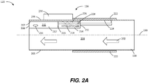
- FIGURE 2A shows the pressure relief system 400 configured with a cover 222 in a closed configuration so that all pressurized air 240 from the APU system 100 is routed to the main engine start system 200.
- FIGURE 2B shows the pressure relief system 400 configured with the cover 222 in an open configuration that allows pressurized air 240 to be vented to an external environment when pressure within the duct 402 exceeds a predetermined amount in order to prevent a surge condition.
- the pressure relief system 400 includes a duct 402 and a pressure relief assembly 401, which is integrated into the duct 402.
- the duct 402 may be a section of ducting that is sized to mate with adjacent sections of the duct system 300 at a location near the load.
- the duct 402 includes an interior volume 242 defined by a sidewall 206.
- the duct 402 may have any cross-sectional shape.
- the duct 402 routes the pressurized air 240 from the duct system 300 downstream of the duct 402 to the main engine start system 200, or other load, upstream of the duct 402.
- the pressure relief assembly 401 includes two chambers separated by a piston 220.
- the first chamber 212 is at least partially defined by the sidewall 206.
- the sidewall 206 becomes an outer wall of the first chamber, while an inner wall 207 is opposite the sidewall 206 and closest to the interior volume 242 of the duct 402.
- a first end wall 208 provides a fixed wall coupling the sidewall 206 to the inner wall 207 at one end of the first chamber 212, while the piston 220 provides a moveable end wall at an opposing end of the first chamber 212. Moving the piston 220 axially parallel to a central axis 210 through the duct 402 changes a first volume 232 of the first chamber 212.
- Pressurized air 240 or other gas within the interior volume 242 of the duct 402 is fluidly coupled to the pressurized air 240 of the first volume 232 of the first chamber 212 through a first orifice 216.
- the first orifice 216 may be sized and shaped as desired and is not limited to the size and shape shown in FIGURES 2A and 2B .
- the pressure relief assembly 401 has a second chamber 214 adjacent to the first chamber 212.
- the second chamber 214 is at least partially defined by the sidewall 206.
- the sidewall 206 becomes the outer wall of the second chamber 214, while the inner wall 207 is opposite the sidewall 206 and closest to the interior volume 242 of the duct 402.
- a second end wall 211 provides a fixed wall coupling the sidewall 206 to the inner wall 207 at one end of the second chamber 214.
- the piston 220 provides a moveable end wall at an opposing end of the second chamber 214 that is shared with the first chamber 212.
- Moving the piston 220 axially parallel to the central axis 210 through the duct 402 changes not only the first volume 232 of the first chamber 212, but also a second volume 234 of the second chamber 214.
- Pressurized air 240 or other gas within the interior volume 242 of the duct 402 is fluidly coupled to the pressurized air 240 of the second volume 234 of the second chamber 214 through a second orifice 218.
- the second orifice 218 may be sized and shaped as desired and is not limited to the size and shape, or to a single orifice, as shown in FIGURES 2A and 2B .
- the piston 220 is free to move axially parallel to the central axis 210.
- the piston 220 is coupled to a cover 222.
- the cover 222 is configured to seal a relief aperture 224 in the sidewall 206 of the duct 402 when positioned in a closed configuration as shown in FIGURE 2A , and to expose the relief aperture to an external environment when positioned in an open configuration as shown in FIGURE 2B .
- the piston 220 simultaneously increases the volume of one chamber and decreases the volume of the other chamber. For example, as the piston 220 moves to the left in FIGURE 2A , the first volume 232 of the first chamber 212 decreases while the second volume 234 of the second chamber 214 increases.
- the cover 222 is coupled to the piston 220, as the piston 220 moves to the left, the cover 222 transitions from the closed configuration shown in FIGURE 2A to the open position shown in FIGURE 2B . Conversely, as the piston 220 moves to the right in FIGURE 2B , the first volume 232 of the first chamber 212 increases while the second volume 234 of the second chamber 214 decreases, transitioning the attached cover 222 from the open configuration shown in FIGURE 2B to the closed configuration shown in FIGURE 2A .
- the piston 220 is biased in a closed position in which the first volume 232 of the first chamber 212 is larger than the second volume 234 of the second chamber 214.
- the piston 220 may be biased against a stopper (not shown) using a spring 226.
- the spring 226 is coupled at a first end to the piston 220 and at a second end to a fixed component of the pressure relief assembly 401.
- the fixed component is a set screw 228.
- the tension force in the spring 226 may be selectively modified with the set screw 228 in order to adjust the amount of force required to move the piston 220 and decrease the first volume 232 of the first chamber 212.
- the piston 220 is set in motion as a result of a pressure differential in the between the pressure of the pressurized air 240 within the first volume 232 of the first chamber 212 and the pressure of the pressurized air 240 within the second volume 234 of the second chamber 214. Because both the first chamber 212 and the second chamber 214 are both exposed to the interior volume 242 of the duct 402 via the first orifice 216 and the second orifice 218, respectively, as the pressure within the interior volume 242 of the duct 402 increases, the pressure within the first volume 232 and the second volume 234 also increases.
- the pressure within the two chambers increases at different rates.
- the resulting pressure differential between the two chambers applies a force to the piston 220, pushing the piston 220 towards the chamber of lower pressure.
- the first volume 232 and the second volume 234 may be equivalent when the cover 222 is in the closed configuration. As long as the area of the second orifice 218 is larger than the area of the first orifice 216, pressurized air or gas from the interior volume 242 of the duct 402 may enter the second chamber 214 more quickly than the first chamber 212. In doing so, the pressure differential between the two chambers increases and the piston 220 is moved to reposition the cover 222 in the open configuration.
- the second volume 234 may be smaller than the first volume 232 when the cover 222 is configured in the closed configuration.
- the second orifice 218 has a larger area than an area of the first orifice 216. Because high pressure air can fill and increase the pressure within the second chamber 214 more quickly than the air can fill and increase the pressure within the first chamber 212 due to the smaller volume of the second chamber 214 and the larger area of the second orifice 218, a pneumatic surge condition that quickly increases the pressure within the duct 402 will create a pressure differential that moves the piston 220 toward the first chamber 212.
- This movement moves the cover 222 to the open configuration of FIGURE 2B , allowing the pressurized air 240 within the duct 402 to escape to the external environment via the relief aperture.
- the pressure differential between the first chamber 212 and the second chamber 214 decreases to a value in which the force created by the pressure differential and applied to the piston 220 is not sufficient to overcome the biasing force on the piston 220 from the spring 226.
- the piston 220 is pulled back into place by the spring 226 so that the attached cover 222 seals the relief aperture 224.
- the pressure relief assembly 401 may include an electronic safety mechanism 230 that is coupled to the cover 222 and is configured to secure the cover 222 in the closed configuration when the electronic safety mechanism 230 is de-energized when a power supply 244 does not transmit electrical power to the electronic safety mechanism 230.
- the electronic safety mechanism 230 may be a solenoid motor that when de-energized, prevents the cover 222 from moving from the closed configuration. In other words, when the power supply 244 de-energized the electronic safety mechanism 230, the cover 222 cannot move the open configuration.
- This safety mechanism 230 may be locked into the closed configuration at any time in which it would not be desirable to open the cover 222, such as during engine start.
- FIGURE 3 shows a perspective view of a pressure relief system 400 according to the present invention. It should be appreciated that all components of the pressure relief system 400 are not shown for clarity purposes. As one example, the spring 226 and set screw 228 are not shown. This view provides a better visualization of the first chamber 212 and the second chamber 214 with the piston 220 providing a movable wall shared by both chambers.
- the cover 222 can slide axially parallel to the central axis 210 to cover and seal the relief aperture 224 in the closed configuration and to expose the relief aperture 224 in the open configuration.
- the configuration of the cover 222 and how the cover 222 seals and exposes the relief aperture 224 is not limited to the configuration shown in FIGURES 2A , 2B , and 3 .
- FIGURES 4A-4C , 5A and 5B illustrate additional configurations for opening and closing the cover 222.
- the mechanical connections of the cover 222 to the piston 220 may be designed in any suitable manner known to those with skill in the art to effectuate the opening and closing operation described below with respect to each embodiment.
- FIGURES 4A-4C are perspective views in which the cover 222 may not fully encompass the outer circumference of the duct 402.
- the cover 222 partially wraps around the outer surface of the duct 402 and is at least as large as the relief aperture 224.
- FIGURE 4A shows the cover 222 positioned in the closed configuration in which the cover 222 is sealing the relief aperture 224 to prevent pressurized air 240 from escaping from the interior volume 242 of the duct 402.
- the cover 222 can open by moving upward away from the relief aperture 224 to expose the relief aperture 224 to the external environment. This movement can be in a direction normal to the central axis 210 as shown in FIGURE 4B .
- the movement of the cover 222 may be rotational such that a portion of the cover 222 moves upward away from the relief aperture 224 to expose the relief aperture 224 to the external environment and allow the excess pressure to be released from the duct 402.
- FIGURES 5A and 5B show perspective views in which the cover 222 can rotate around the central axis 210 of the duct 402 to cover the relief aperture 224 in the closed configuration and to expose the relief aperture 224 in the open configuration.
- the cover 222 has a cover aperture 502 that when is not aligned with the relief aperture 224 in the closed configuration.
- transitioning the cover 222 from the closed configuration to the open configuration involves rotating the cover 222 until the cover aperture 502 aligns with the relief aperture 224 to expose the relief aperture 224 to the external environment.
- FIGURE 6 shows a routine 600 for providing pressure relief within a duct 402 fluidly coupled to a load compressor 103 and a load according to the present invention. It should be appreciated that more or fewer operations may be performed than shown in the figures and described herein. These operations may also be performed in parallel, or in a different order than those described herein.
- the routine 600 begins at operation 602, where if the pressure relief system 400 is being retrofit into an existing APU system, a portion of the duct system 300 is replaced with the duct 402 near the load. At operation 604, a portion of the gas within the interior volume 242 of the duct 402 is received within the first chamber 212 through the first orifice 216. At the same time, at operation 606, another portion of the gas within the interior volume 242 of the duct 402 is received within the second chamber 214 through the second orifice 218.
- the gas within the interior volume 242 of the duct 402 enters the second chamber 214 more quickly, and the pressure builds within more quickly, than the first chamber 212.
- the pressure differential between the first chamber 212 and the second chamber 214 increases as the pressure within the interior volume 242 of the duct 402 increases. Conversely, as the pressure within the interior volume 242 of the duct 402 decreases, the pressure differential decreases to a level below that of the force from the spring 226.
- the piston 220 moves. If the pressure differential between the first chamber 212 and the second chamber 214 increases due to an increase of pressure within the duct 402, then the pressure differential between the chambers causes the piston 220 to move towards the first chamber 212. However, if the pressure differential between the first chamber 212 and the second chamber 214 decreases due to a decrease of pressure within the duct 402, then when the force from the spring 226 is greater than any force on the piston 220 from the pressure differential between the chambers, the piston 220 moves towards the second chamber 214.
- the cover 222 is repositioned, transitioning between open and closed configurations, as a result of the piston 220 movement. Because the cover 222 is coupled to the piston 220, as the piston 220 moves towards the first chamber 212, the cover 222 moves from the closed configuration to the open configuration to allow for pressurized gas within the interior volume 242 of the duct 402 to escape to the external environment. As the piston 220 moves towards the second chamber 214, the cover 222 moves from the open configuration to the closed configuration to seal the relief aperture 224 and prevent pressurized gas from escaping to the external environment. From operation 612, the routine 600 ends.
Landscapes
- Engineering & Computer Science (AREA)
- General Engineering & Computer Science (AREA)
- Mechanical Engineering (AREA)
- Aviation & Aerospace Engineering (AREA)
- Structures Of Non-Positive Displacement Pumps (AREA)
- Safety Valves (AREA)
Abstract
Description
- Pneumatic systems often include one or more compressors that can experience surge events in which pressure associated with the load may rapidly increase. At least some aircraft engines are typically started with the assistance of an auxilliary power unit (APU). The APU provides the aircraft with electrical and pneumatic power. Pressurized air from the APU load compressor is routed to an aircraft engine via a duct system where the pressurized air drives a turbine at the engine to generate power and rotation on the engine shaft for engine start. If the aircraft engine, or other pneumatic load, stops utilizing the pressurized air, then the potential exists for a surge condition in which the pressure within the duct increases back to the APU. Conventionally, a surge valve is integrated into the APU to prevent surge conditions. However, the surge valve may take more time than is desirable to open. Because the surge valve is physically located within or at the APU, if the surge valve does not respond quickly enough, then the surge condition may reach the compressor before the integrated surge protection valve can open.
- Surge protection within APUs is typically designed for a particular aircraft and engine platform. If components within that aircraft or engine system are modified, the surge protection may not be adequate. For example, if an aircraft is upgraded with new engines that have different starting and operating specifications than the engines for which the APU was originally utilized, then the surge protection that is integrated with the APU may not be adequate. Redesigning or replacing the APU within an aircraft to accommodate engine or other aircraft component changes may be costly and time consuming.
- It is with respect to these considerations and others that the disclosure made herein is presented.
- It should be appreciated that this Summary is provided to introduce a selection of concepts in a simplified form that are further described below in the Detailed Description. This Summary is not intended to be used to limit the scope of the claimed subject matter.
- Concepts and technologies described herein provide for a pressure relief assembly and system and corresponding method for providing pressure relief remote from, and independent of, the surge protection system typically integrated into a load compressor. According to one aspect, a pressure relief assembly includes a cover, a first chamber, a second chamber, and a piston. The cover is configured to seal a relief aperture in a sidewall of a duct when the cover is in a closed configuration. The cover is configured to expose the relief aperture to an external environment when positioned in an open configuration. The first chamber is partially defined by the sidewall of the duct and has a first volume open to the interior volume of the duct via a first orifice. The second chamber is partially defined by the sidewall of the duct and has a second volume that is open to the interior volume of the duct via a second orifice. The second orifice has a larger area than the area of the first orifice. The piston is connected to the cover and is positioned between the first and second chambers. The piston changes the volumes of the first and second chambers in response to a change in pressure within the chambers.
- According to yet another aspect, a method for providing pressure relief is provided. The method includes receiving a portion of a gas from an interior of a duct through a first orifice at a first chamber of a pressure relief assembly. A second portion of the gas is received from the interior of the duct through a second orifice at a second chamber of the pressure relief assembly. The second orifice has a larger area than that of the first orifice. In response to a pressure differential between first and second chambers, a piston is moved, decreasing a volume of the first chamber while increasing a volume of the second chamber. When the piston moves, a cover connected to the piston moves from a closed configuration sealing a gas within the duct to an open configuration in which the cover exposes a relief aperture in the sidewall of the duct to allow the gas within the duct to escape to an external environment.
- According to another aspect, a pressure relief system is provided for providing pressurized air to an aircraft engine with protection from pressure surges. The system includes an APU relief valve and a pressure relief assembly. The APU relief valve is positioned near a load compressor. The pressure relief assembly is integrated into a sidewall of a duct and is positioned downstream of the APU relief valve near a main engine start system associated with the aircraft engine.
- The features, functions, and advantages that have been discussed can be achieved independently in various embodiments of the present disclosure or may be combined in yet other embodiments, further details of which can be seen with reference to the following description and drawings.
-
-
FIGURE 1 is a block diagram of an auxilliary power unit (APU) system, main engine start system, and remote pressure relief system according to the present invention; -
FIGURES 2A and2B are cross-sectional diagrams of a duct and pressure relief assembly in closed and open configurations, respectively, illustrating various aspects of a pressure relief system according to the present invention; -
FIGURE 3 is a perspective view of a pressure relief system according to the present invention; -
FIGURE 4A is a perspective view of a pressure relief system showing an embodiment of a cover in a closed configuration according to the present invention; -
FIGURES 4B and 4C are perspective views of the pressure relief system ofFIGURE 4A showing embodiments of the cover in an open according to the present invention; -
FIGURES 5A and 5B are perspective views of a pressure relief system in closed and open configurations, respectively, showing embodiments of a cover having a cover aperture according to the present invention; and -
FIGURE 6 is a flow diagram showing a method for providing pressure relief within a duct fluidly coupled to a compressor and a load according to the present invention. - The following detailed description is directed to a pressure relief assembly and system and corresponding method for utilizing the same. As discussed above, conventional auxilliary power unit (APU) systems are designed for a particular platform having specific operating parameters. When components of that platform change, the operating parameters may also change. Unless the APU is modified, or the integrated APU relief valve incorporated into the APU is replaced, the load compressor within the APU may be subjected to a surge in pressure. Replacing or redesigning the APU is a costly solution.
- Utilizing the concepts and technologies described herein, a pressure relief assembly may be integrated into a duct and positioned close to the pneumatic load, such as the engine start system. By positioning the pressure relief assembly close to the load rather than close to the APU as is typical, a flow sink is created in a position where the surge condition is initiated, decreasing the burden on the APU relief valve. The pressure relief assembly described herein effectively becomes a remote and independent sensor for the APU load compressor, reacting to a surge condition at a distant location from the compressor at or near the load, which is the source of the surge. The time delay between the surge initiation and the activation of the surge protection approaches zero since the pressure relief assembly is located proximate to the load rather than the APU.
- Another benefit of the pressure relief assembly described herein as compared to the conventional APU and integrated APU relief valve is the integration of the pressure relief assembly into a section of a duct in a low profile manner. The portion of the duct with the pressure relief assembly may be placed into an existing duct system at a desired location without removing, replacing, or modifying the existing APU or APU relief valve. The low profile nature of the pressure relief assembly and corresponding duct allows for easy installation within an aircraft where space and weight considerations are significant.
- Moreover, conventional APU systems utilize two controllers and an APU relief valve. One controller monitors and responds to changes in pressure, while the second controller monitors and responds to flow rates. In contrast, the pressure relief assembly described below does not utilize any electronics or controllers for operation. Rather, the configuration of the pressure relief assembly responds to pressure gradients to mechanically move a piston and corresponding cover to seal and expose a relief aperture in the duct.
- In the following detailed description, references are made to the accompanying drawings that form a part hereof, and which are shown by way of illustration. Referring now to the drawings, in which like numerals represent like elements through the several figures, a pressure relief assembly, system, and corresponding method for using the same according to the present invention will be described.
-
FIGURE 1 shows a block diagram of anAPU system 100, the main engine start system 200, and remote pressure relief system 400 according to the present invention. TheAPU system 100 and main engine start system 200 are illustrated with only certain components used in the discussion below for clarity purposes. It should be appreciated that theAPU system 100 and main engine start system 200 are not limited to the components shown and described herein, and may include greater or fewer components than those illustrated inFIGURE 1 . - The
APU system 100 includes a power section 101, connected by ashaft 102 to a load compressor 103, and anAPU relief valve 104. The various examples discussed below will be described in the context of anAPU system 100 providing pressurized air to a main engine start system 200 of an aircraft for starting purposes. The main engine start system 200 includes an air turbine starter 201, connected by ashaft 202 to the main engine compressor 203, and a quick-closingvalve 204 to initiate and end the start sequence. Accordingly, for the purposes of this disclosure, theAPU system 100 will be described as a pneumatic source of pressurized air flow to the load, which is the main engine start system 200 of the aircraft. However, it should be understood that theAPU system 100 may include any type of pneumatic source providing pressurized gas to any type of load, and is not limited to anAPU system 100 providing pressurized air to the main engine start system 200 of an ai rcraft. - The pressurized air is routed from the
APU system 100 to the main engine start system 200 load via a duct system 300. The duct system 300 includes any length and number of duct sections coupled together to form a pathway from theAPU system 100 to the main engine start system 200. In conventional aircraft, theAPU system 100 is often located in the rear of the aircraft, with ducts routing air forward to an aircraft engine mounted under a wing of the aircraft. Conventionalaircraft APU systems 100 include anAPU relief valve 104 integrated with the load compressor 103. TheAPU relief valve 104 is located at or near the load compressor 103 and operates to relieve pressure within the duct system 300 to prevent surge conditions from entering the load compressor 103 and causing operational transients of the load compressor 103. However, as discussed above, theAPU relief valves 104 associated with conventional load compressors 103 are not always adequate to prevent surge damage due to the positioning of the valve close to the load compressor 103, which does not allow for sufficient time for the valve to dissipate the pressure before the surge enters the APU load compressor 103, as well as due to theAPU relief valve 104 being incapable of handling surge conditions associated with a new or modified aircraft main engine start system 200 or air turbine starter 201 for which theAPU relief valve 104 was not designed. - The main engine start system 200 may also include a quick-closing
valve 204. The quick-closingvalve 204 is functional to stop the flow of pressurized air to the load when the load no longer needs or is incapable of receiving the pressurized air. Closing this valve during the operation of the load compressor 103 may create a surge condition as the pressurized air within the duct system has no flow sink, or no place to go. In conventional APU systems, this buildup in pressure increases rearward toward the load compressor 103. Due to the length of the duct system 300 and positioning of theAPU relief valve 104, the pressure increase within the duct system 300 may be too severe for theAPU relief valve 104 to dissipate, or dissipate quickly enough, before reaching the load compressor 103. - According to the present invention, a pressure relief system 400 is positioned proximate to the main engine start system 200. The pressure relief system 400 responds to an increase in pressure within the duct system 300 to open a relief aperture and vent pressurized air to the external environment surrounding the duct system 300. As shown in
FIGURE 1 , the pressure relief system 400 is positioned proximate to the main engine start system 200, in contrast to theAPU relief valve 104, which is positioned proximate to the load compressor 103. Another way of describing the positioning of the pressure relief system 400 is that the pressure relief system 400 is positioned at a location within the duct system 300 that is closer to the load, or main engine start system 200, than to theAPU system 100. - The precise positioning of the pressure relief system 400 is dependent upon the particular application. Specifically, the characteristics of the
APU system 100, theAPU relief valve 104, and the main engine start system 200 or other load, as well as the sizing and length of the duct system 300, are all factors to be considered when determining the placement of the pressure relief system 400. The distance that the load is from theAPU system 100 and the speed at which theAPU relief valve 104 operates may drive the placement of the pressure relief system 400. In sum, the remote placement of the pressure relief system 400 away from theAPU system 100 provides relief so that theAPU system 100 is not as sensitive to the load going offline too quickly, enabling the flow from theAPU system 100 to be maintained even when the load is unable to accept the flow. - The pressure relief system 400 may include a pressure relief assembly 401 integrated into a duct 402. The duct 402 may include any section or portion of ducting within the duct system 300. For example, a section of a duct 402 may be fitted with the pressure relief assembly 401 described below and used to replace a similar section of the duct system 300 at the desired location. Moreover, when retrofitting a conventional APU system with the pressure relief system 400 described herein, an applicable portion of the duct system 300 may be removed and replaced with the pressure relief system 400 that includes the duct 402 with integrated pressure relief assembly 401. Removing and replacing the applicable portion of the duct system 300 may include removing fasteners connecting the portion to adjacent portions of the duct system 300, removing the portion, positioning the duct 402 in place, and utilizing fasteners to secure the duct 402 to adjacent portions of the duct system 300. Alternatively, an applicable portion of the duct system 300 may be cut away and the duct 402 with integrated pressure relief assembly 401 may be spliced into the location where the portion was removed using fasteners, welds, adhesive, or any suitable mechansim for securing the duct 402 in place.
- Turning now to
FIGURES 2A and2B , a pressure relief system 400 will be described in greater detail.FIGURE 2A shows the pressure relief system 400 configured with acover 222 in a closed configuration so that all pressurized air 240 from theAPU system 100 is routed to the main engine start system 200.FIGURE 2B shows the pressure relief system 400 configured with thecover 222 in an open configuration that allows pressurized air 240 to be vented to an external environment when pressure within the duct 402 exceeds a predetermined amount in order to prevent a surge condition. - The pressure relief system 400 includes a duct 402 and a pressure relief assembly 401, which is integrated into the duct 402. As previously discussed, the duct 402 may be a section of ducting that is sized to mate with adjacent sections of the duct system 300 at a location near the load. The duct 402 includes an interior volume 242 defined by a
sidewall 206. The duct 402 may have any cross-sectional shape. The duct 402 routes the pressurized air 240 from the duct system 300 downstream of the duct 402 to the main engine start system 200, or other load, upstream of the duct 402. - The pressure relief assembly 401 includes two chambers separated by a
piston 220. Thefirst chamber 212 is at least partially defined by thesidewall 206. Thesidewall 206 becomes an outer wall of the first chamber, while aninner wall 207 is opposite thesidewall 206 and closest to the interior volume 242 of the duct 402. Afirst end wall 208 provides a fixed wall coupling thesidewall 206 to theinner wall 207 at one end of thefirst chamber 212, while thepiston 220 provides a moveable end wall at an opposing end of thefirst chamber 212. Moving thepiston 220 axially parallel to acentral axis 210 through the duct 402 changes afirst volume 232 of thefirst chamber 212. Pressurized air 240 or other gas within the interior volume 242 of the duct 402 is fluidly coupled to the pressurized air 240 of thefirst volume 232 of thefirst chamber 212 through afirst orifice 216. Thefirst orifice 216 may be sized and shaped as desired and is not limited to the size and shape shown inFIGURES 2A and2B . Similarly, there may be more than onefirst orifice 216 in theinner wall 207 of thefirst chamber 212 that allows pressurized air 240 to flow between the duct 402 and thefirst chamber 212. - The pressure relief assembly 401 has a
second chamber 214 adjacent to thefirst chamber 212. Thesecond chamber 214 is at least partially defined by thesidewall 206. As with thefirst chamber 212, thesidewall 206 becomes the outer wall of thesecond chamber 214, while theinner wall 207 is opposite thesidewall 206 and closest to the interior volume 242 of the duct 402. Asecond end wall 211 provides a fixed wall coupling thesidewall 206 to theinner wall 207 at one end of thesecond chamber 214. As stated above, thepiston 220 provides a moveable end wall at an opposing end of thesecond chamber 214 that is shared with thefirst chamber 212. Moving thepiston 220 axially parallel to thecentral axis 210 through the duct 402 changes not only thefirst volume 232 of thefirst chamber 212, but also asecond volume 234 of thesecond chamber 214. Pressurized air 240 or other gas within the interior volume 242 of the duct 402 is fluidly coupled to the pressurized air 240 of thesecond volume 234 of thesecond chamber 214 through asecond orifice 218. Thesecond orifice 218 may be sized and shaped as desired and is not limited to the size and shape, or to a single orifice, as shown inFIGURES 2A and2B . - The
piston 220 is free to move axially parallel to thecentral axis 210. Thepiston 220 is coupled to acover 222. Thecover 222 is configured to seal arelief aperture 224 in thesidewall 206 of the duct 402 when positioned in a closed configuration as shown inFIGURE 2A , and to expose the relief aperture to an external environment when positioned in an open configuration as shown inFIGURE 2B . As thepiston 220 moves, thepiston 220 simultaneously increases the volume of one chamber and decreases the volume of the other chamber. For example, as thepiston 220 moves to the left inFIGURE 2A , thefirst volume 232 of thefirst chamber 212 decreases while thesecond volume 234 of thesecond chamber 214 increases. Because thecover 222 is coupled to thepiston 220, as thepiston 220 moves to the left, thecover 222 transitions from the closed configuration shown inFIGURE 2A to the open position shown inFIGURE 2B . Conversely, as thepiston 220 moves to the right inFIGURE 2B , thefirst volume 232 of thefirst chamber 212 increases while thesecond volume 234 of thesecond chamber 214 decreases, transitioning the attachedcover 222 from the open configuration shown inFIGURE 2B to the closed configuration shown inFIGURE 2A . - Also as shown in
FIGURE 2A , thepiston 220 is biased in a closed position in which thefirst volume 232 of thefirst chamber 212 is larger than thesecond volume 234 of thesecond chamber 214. Thepiston 220 may be biased against a stopper (not shown) using aspring 226. Thespring 226 is coupled at a first end to thepiston 220 and at a second end to a fixed component of the pressure relief assembly 401. According to one embodiment, the fixed component is aset screw 228. By coupling thespring 226 to aset screw 228, the tension force in thespring 226 may be selectively modified with theset screw 228 in order to adjust the amount of force required to move thepiston 220 and decrease thefirst volume 232 of thefirst chamber 212. - The
piston 220 is set in motion as a result of a pressure differential in the between the pressure of the pressurized air 240 within thefirst volume 232 of thefirst chamber 212 and the pressure of the pressurized air 240 within thesecond volume 234 of thesecond chamber 214. Because both thefirst chamber 212 and thesecond chamber 214 are both exposed to the interior volume 242 of the duct 402 via thefirst orifice 216 and thesecond orifice 218, respectively, as the pressure within the interior volume 242 of the duct 402 increases, the pressure within thefirst volume 232 and thesecond volume 234 also increases. However, due to the differing volumes of thefirst volume 232 and thesecond volume 234, and due to the differing areas of thefirst orifice 216 and of thesecond orifice 218, the pressure within the two chambers increases at different rates. The resulting pressure differential between the two chambers applies a force to thepiston 220, pushing thepiston 220 towards the chamber of lower pressure. - The
first volume 232 and thesecond volume 234 may be equivalent when thecover 222 is in the closed configuration. As long as the area of thesecond orifice 218 is larger than the area of thefirst orifice 216, pressurized air or gas from the interior volume 242 of the duct 402 may enter thesecond chamber 214 more quickly than thefirst chamber 212. In doing so, the pressure differential between the two chambers increases and thepiston 220 is moved to reposition thecover 222 in the open configuration. - As seen in
FIGURE 2A , thesecond volume 234 may be smaller than thefirst volume 232 when thecover 222 is configured in the closed configuration. Moreover, thesecond orifice 218 has a larger area than an area of thefirst orifice 216. Because high pressure air can fill and increase the pressure within thesecond chamber 214 more quickly than the air can fill and increase the pressure within thefirst chamber 212 due to the smaller volume of thesecond chamber 214 and the larger area of thesecond orifice 218, a pneumatic surge condition that quickly increases the pressure within the duct 402 will create a pressure differential that moves thepiston 220 toward thefirst chamber 212. This movement moves thecover 222 to the open configuration ofFIGURE 2B , allowing the pressurized air 240 within the duct 402 to escape to the external environment via the relief aperture. When enough of the pressurized air 240 vents to the external environment, the pressure differential between thefirst chamber 212 and thesecond chamber 214 decreases to a value in which the force created by the pressure differential and applied to thepiston 220 is not sufficient to overcome the biasing force on thepiston 220 from thespring 226. When this happens, thepiston 220 is pulled back into place by thespring 226 so that the attachedcover 222 seals therelief aperture 224. - The pressure relief assembly 401 may include an
electronic safety mechanism 230 that is coupled to thecover 222 and is configured to secure thecover 222 in the closed configuration when theelectronic safety mechanism 230 is de-energized when a power supply 244 does not transmit electrical power to theelectronic safety mechanism 230. As an example, theelectronic safety mechanism 230 may be a solenoid motor that when de-energized, prevents thecover 222 from moving from the closed configuration. In other words, when the power supply 244 de-energized theelectronic safety mechanism 230, thecover 222 cannot move the open configuration. Thissafety mechanism 230 may be locked into the closed configuration at any time in which it would not be desirable to open thecover 222, such as during engine start. -
FIGURE 3 shows a perspective view of a pressure relief system 400 according to the present invention. It should be appreciated that all components of the pressure relief system 400 are not shown for clarity purposes. As one example, thespring 226 and setscrew 228 are not shown. This view provides a better visualization of thefirst chamber 212 and thesecond chamber 214 with thepiston 220 providing a movable wall shared by both chambers. Thecover 222 can slide axially parallel to thecentral axis 210 to cover and seal therelief aperture 224 in the closed configuration and to expose therelief aperture 224 in the open configuration. The configuration of thecover 222 and how thecover 222 seals and exposes therelief aperture 224 is not limited to the configuration shown inFIGURES 2A ,2B , and3 . Rather, any configuration in which thecover 222 may be opened and closed via the movement of thepiston 220 may be used.FIGURES 4A-4C ,5A and 5B illustrate additional configurations for opening and closing thecover 222. For clarity purposes, all components of the pressure relief system 400 other than the duct 402, thecover 222, and therelief aperture 224 have been removed. The mechanical connections of thecover 222 to thepiston 220 may be designed in any suitable manner known to those with skill in the art to effectuate the opening and closing operation described below with respect to each embodiment. -
FIGURES 4A-4C are perspective views in which thecover 222 may not fully encompass the outer circumference of the duct 402. In these examples, thecover 222 partially wraps around the outer surface of the duct 402 and is at least as large as therelief aperture 224.FIGURE 4A shows thecover 222 positioned in the closed configuration in which thecover 222 is sealing therelief aperture 224 to prevent pressurized air 240 from escaping from the interior volume 242 of the duct 402. As shown inFIGURE 4B , thecover 222 can open by moving upward away from therelief aperture 224 to expose therelief aperture 224 to the external environment. This movement can be in a direction normal to thecentral axis 210 as shown inFIGURE 4B . Alternatively, as shown inFIGURE 4C , the movement of thecover 222 may be rotational such that a portion of thecover 222 moves upward away from therelief aperture 224 to expose therelief aperture 224 to the external environment and allow the excess pressure to be released from the duct 402. -
FIGURES 5A and 5B show perspective views in which thecover 222 can rotate around thecentral axis 210 of the duct 402 to cover therelief aperture 224 in the closed configuration and to expose therelief aperture 224 in the open configuration. As seen inFIGURE 5A , thecover 222 has acover aperture 502 that when is not aligned with therelief aperture 224 in the closed configuration. However, as seen inFIGURE 5B , transitioning thecover 222 from the closed configuration to the open configuration involves rotating thecover 222 until thecover aperture 502 aligns with therelief aperture 224 to expose therelief aperture 224 to the external environment. -
FIGURE 6 shows a routine 600 for providing pressure relief within a duct 402 fluidly coupled to a load compressor 103 and a load according to the present invention. It should be appreciated that more or fewer operations may be performed than shown in the figures and described herein. These operations may also be performed in parallel, or in a different order than those described herein. - The routine 600 begins at
operation 602, where if the pressure relief system 400 is being retrofit into an existing APU system, a portion of the duct system 300 is replaced with the duct 402 near the load. Atoperation 604, a portion of the gas within the interior volume 242 of the duct 402 is received within thefirst chamber 212 through thefirst orifice 216. At the same time, atoperation 606, another portion of the gas within the interior volume 242 of the duct 402 is received within thesecond chamber 214 through thesecond orifice 218. - Because the
second orifice 218 of thesecond chamber 214 is larger in area than thefirst orifice 216 of thefirst chamber 212, and because thesecond volume 234 of thesecond chamber 214 is smaller than thefirst volume 232 of thefirst chamber 212, the gas within the interior volume 242 of the duct 402 enters thesecond chamber 214 more quickly, and the pressure builds within more quickly, than thefirst chamber 212. As a result, atoperation 608, the pressure differential between thefirst chamber 212 and thesecond chamber 214 increases as the pressure within the interior volume 242 of the duct 402 increases. Conversely, as the pressure within the interior volume 242 of the duct 402 decreases, the pressure differential decreases to a level below that of the force from thespring 226. - At
operation 610, in response to the pressure differential increase or decrease, thepiston 220 moves. If the pressure differential between thefirst chamber 212 and thesecond chamber 214 increases due to an increase of pressure within the duct 402, then the pressure differential between the chambers causes thepiston 220 to move towards thefirst chamber 212. However, if the pressure differential between thefirst chamber 212 and thesecond chamber 214 decreases due to a decrease of pressure within the duct 402, then when the force from thespring 226 is greater than any force on thepiston 220 from the pressure differential between the chambers, thepiston 220 moves towards thesecond chamber 214. - At
operation 612, thecover 222 is repositioned, transitioning between open and closed configurations, as a result of thepiston 220 movement. Because thecover 222 is coupled to thepiston 220, as thepiston 220 moves towards thefirst chamber 212, thecover 222 moves from the closed configuration to the open configuration to allow for pressurized gas within the interior volume 242 of the duct 402 to escape to the external environment. As thepiston 220 moves towards thesecond chamber 214, thecover 222 moves from the open configuration to the closed configuration to seal therelief aperture 224 and prevent pressurized gas from escaping to the external environment. Fromoperation 612, the routine 600 ends. - Further, the disclosure comprises embodiments according to the following clauses:
- Clause 1. A pressure relief assembly for use with a duct having an interior volume defined by a sidewall and a relief aperture defined through the sidewall of the duct, the pressure relief assembly comprising: a cover configured to seal the relief aperture when positioned in a closed configuration and to expose the relief aperture to an external environment when positioned in an open configuration; a first chamber at least partially defined by the sidewall and having a first volume fluidly coupled to the interior volume of the duct through a first orifice; a second chamber at least partially defined by the sidewall and having a second volume fluidly coupled to the interior volume of the duct through a second orifice, the second orifice having a larger area than an area of the first orifice; and a piston coupled to the cover, positioned between the first chamber and the second chamber and defining a wall of the first chamber and the second chamber, and configured to change the first volume and the second volume in response to a change in pressure in at least the first chamber or the second chamber.
- Clause 2. The pressure relief assembly of Clause 1, wherein the cover slides axially parallel to a central axis of the duct to cover the relief aperture in the closed configuration and to expose the relief aperture in the open configuration.
- Clause 3. The pressure relief assembly of Clause 1, wherein the cover rotates around a central axis of the duct to cover the relief aperture in the closed configuration and to expose the relief aperture in the open configuration.
- Clause 4. The pressure relief assembly of Clause 1, wherein at least a portion of the cover moves upward away from the relief aperture to expose the relief aperture in the open configuration and moves downward toward the relief aperture to cover the relief aperture in the closed configuration.
- Clause 5. The pressure relief assembly of any one of Clauses 1 to 4, further comprising a spring coupled at a first end to the piston and at a second end to a fixed component of the pressure relief assembly, the spring configured to bias the cover coupled to the piston in the closed configuration.
- Clause 6. The pressure relief assembly of Clause 5, wherein the fixed component comprises a set screw configured to selectively modify a tension in the spring to adjust a pressure differential between the first chamber and the second chamber sufficient to transition the cover between the closed configuration and the open configuration.
- Clause 7. The pressure relief assembly of any one of Clauses 1 to 6, further comprising an electronic safety mechanism coupled to the cover and configured to secure the cover in the closed configuration when de-energized.
- Clause 8. The pressure relief assembly of Clause 7, wherein the electronic safety mechanism comprises a solenoid motor.
- Clause 9. The pressure relief assembly of any one of Clauses 1 to 8, wherein the pressure relief assembly is integrated into the duct, wherein the duct is configured to be positioned within a duct system associated with an auxiliary power unit (APU) of an aircraft such that airflow from the APU to an aircraft engine flows through the duct.
- Clause 10. The pressure relief assembly of Clause 9, wherein the duct is positioned closer to the aircraft engine than the APU within the duct system.
- Clause 11. The pressure relief assembly of any one of Clauses 1 to 10, wherein the second volume is smaller than the first volume when the cover is configured in the closed configuration.
- Clause 12. A pressure relief system for providing pressurized air to an aircraft engine with protection from pressure surges, the system comprising: an APU relief valve positioned proximate to a load compressor; and the pressure relief assembly of any one of Clauses 1 to 11 integrated into the sidewall of the duct and positioned downstream of the APU relief valve proximate to a main engine start system associated with the aircraft engine.
- Clause 13. A method for providing pressure relief within a duct fluidly coupled to a compressor and a load, the method comprising: receiving a first portion of a gas from an interior volume of the duct through a first orifice at a first chamber of a pressure relief assembly at least partially defined by a sidewall of the duct; receiving a second portion of the gas from the interior volume of the duct through a second orifice at a second chamber of the pressure relief assembly at least partially defined by the sidewall of the duct, the second orifice having a larger area than an area of the first orifice; in response to a pressure differential between the first chamber and the second chamber, moving a piston and decreasing a first volume of the first chamber while increasing a second volume of the second chamber; and in response to moving the piston, repositioning a cover coupled to the piston to transition from a closed configuration in which the gas is sealed within the duct to an open configuration in which the interior volume of the duct is exposed to an external environment via a relief aperture in the sidewall of the duct to allow the gas to escape from the interior volume of the duct.
- Clause 14. The method of Clause 13, wherein repositioning the cover comprises sliding the cover axially parallel to a central axis of the duct to expose the relief aperture in the open configuration.
- Clause 15. The method of Clause 13, wherein repositioning the cover comprises rotating the cover around a central axis of the duct to expose the relief aperture in the open configuration.
- Clause 16. The method of Clause 13, wherein repositioning the cover comprises raising a portion of the cover upward away from the relief aperture to expose the relief aperture in the open configuration.
- Clause 17. The method of any one of Clauses 13 to 16, further comprising: in response to the pressure differential returning to a value in which a biasing spring force overcomes a force associated with the pressure differential, moving the piston to increase the first volume and decrease the second volume; and in response to moving the piston to increase the first volume and decrease the second volume, repositioning the cover coupled to the piston to transition from the open configuration to the closed configuration.
- Clause 18. The method of any one of Clauses 13 to 17, further comprising: removing a portion of a duct system associated with an APU in an aircraft proximate to the load, wherein the load comprises an aircraft engine; replacing the portion of the duct system with the duct having the pressure relief assembly such that in increase in pressure within the pressurized gas flow proximate to the aircraft engine increases the pressure differential between the first chamber and the second chamber.
- Clause 19. A pressure relief system for providing pressurized air to an aircraft engine with protection from pressure surges, the system comprising: an APU relief valve positioned proximate to a load compressor; and a pressure relief assembly integrated into a sidewall of a duct and positioned downstream of the APU relief valve proximate to a main engine start system associated with the aircraft engine.
- Clause 20. The pressure relief system of Clause 19, wherein the pressure relief assembly comprises: a cover configured to seal a relief aperture defined through a sidewall of the duct when positioned in a closed configuration and to expose the relief aperture to an external environment when positioned in an open configuration; a first chamber at least partially defined by the sidewall of the duct and having a first volume fluidly coupled to the interior volume of the duct through a first orifice, a second chamber at least partially defined by the sidewall and having a second volume fluidly coupled to the interior volume of the duct through a second orifice, the second orifice having a larger area than an area of the first orifice; and a piston coupled to the cover, positioned between the first chamber and the second chamber and defining a wall of the first chamber and the second chamber, and configured to change the first volume and the second volume in response to a change in pressure in at least the first chamber or the second chamber.
- Clause 21. The pressure relief system of Clause 20, wherein the cover slides axially parallel to a central axis of the duct to cover the relief aperture in the closed configuration and to expose the relief aperture in the open configuration, wherein the cover rotates around the central axis of the duct to cover the relief aperture in the closed configuration and to expose the relief aperture in the open configuration, or wherein at least a portion of the cover moves upward away from the relief aperture to expose the relief aperture in the open configuration and moves downward toward the relief aperture to cover the relief aperture in the closed configuration.
- Clause 22. Aircraft comprising a pressure relief assembly according to any of the preceding clauses 1-12, or a pressure relief system according to any of the preceding clauses 19-21.
- Based on the foregoing, it should be appreciated that technologies for a pressure relief assembly and system for use with a duct to protect an associated compressor, and a corresponding method for utilizing the same are provided herein. The subject matter described above is provided by way of illustration only and should not be construed as limiting. Various modifications and changes may be made to the subject matter described herein without following the example embodiments and applications illustrated and described, and without departing from the true spirit and scope of the present disclosure, which is set forth in the following claims.
Claims (15)
- A pressure relief assembly (401) for use with a duct (402) having an interior volume (242) defined by a sidewall (206) and a relief aperture (224) defined through the sidewall of the duct, the pressure relief assembly comprising:a cover (222) configured to seal the relief aperture when positioned in a closed configuration and to expose the relief aperture to an external environment when positioned in an open configuration;a first chamber (212) at least partially defined by the sidewall and having a first volume (232) fluidly coupled to the interior volume of the duct through a first orifice (216);a second chamber (214) at least partially defined by the sidewall and having a second volume (234) fluidly coupled to the interior volume of the duct through a second orifice (218), the second orifice having a larger area than an area of the first orifice; anda piston (220) coupled to the cover, positioned between the first chamber and the second chamber and defining a wall of the first chamber and the second chamber, and configured to change the first volume and the second volume in response to a change in pressure in at least the first chamber or the second chamber.
- The pressure relief assembly (401) of claim 1, wherein the cover (222) slides axially parallel to a central axis (210) of the duct (402) to cover the relief aperture (224) in the closed configuration and to expose the relief aperture in the open configuration.
- The pressure relief assembly (401) of claim 1, wherein the cover (222) rotates around a central axis (210) of the duct (402) to cover the relief aperture (224) in the closed configuration and to expose the relief aperture in the open configuration.
- The pressure relief assembly (401) of claim 1, wherein at least a portion of the cover (222) moves upward away from the relief aperture (224) to expose the relief aperture in the open configuration and moves downward toward the relief aperture to cover the relief aperture in the closed configuration.
- The pressure relief assembly (401) of any one of claims 1 to 4, further comprising a spring (226) coupled at a first end to the piston (220) and at a second end to a fixed component of the pressure relief assembly, the spring configured to bias the cover (222) coupled to the piston in the closed configuration.
- The pressure relief assembly (401) of claim 5, wherein the fixed component comprises a set screw (228) configured to selectively modify a tension in the spring (226) to adjust a pressure differential between the first chamber (212) and the second chamber (214) sufficient to transition the cover (222) between the closed configuration and the open configuration.
- The pressure relief assembly (401) of any one of claims 1 to 6, further comprising an electronic safety mechanism (230) coupled to the cover (222) and configured to secure the cover in the closed configuration when de-energized, preferably wherein the electronic safety mechanism comprises a solenoid motor.
- The pressure relief assembly (401) of any one of claims 1 to 7, wherein the pressure relief assembly is integrated into the duct (402), wherein the duct is configured to be positioned within a duct system (300) associated with an auxiliary power unit (APU) system (100) of an aircraft such that airflow from the APU system to an aircraft engine flows through the duct.
- The pressure relief assembly (401) of claim 8, wherein the duct (402) is positioned closer to the aircraft engine than the APU system (100) within the duct system (300).
- The pressure relief assembly (401) of any one of claims 1 to 9, wherein the second volume (234) is smaller than the first volume (232) when the cover (222) is configured in the closed configuration.
- A pressure relief system (400) for providing pressurized air to an aircraft engine with protection from pressure surges, the system comprising:an APU relief valve (104) positioned proximate to a load compressor (103); andthe pressure relief assembly (401) of any one of Claims 1 to 10 integrated into the sidewall (206) of the duct (402) and positioned downstream of the APU relief valve proximate to a main engine start system (200) associated with the aircraft engine.
- A method (600) for providing pressure relief within a duct (402) fluidly coupled to a compressor (103) and a load, the method comprising:receiving (604) a first portion of a gas from an interior volume (242) of the duct through a first orifice (216) at a first chamber (212) of a pressure relief assembly (401) at least partially defined by a sidewall (206) of the duct;receiving (606) a second portion of the gas from the interior volume of the duct through a second orifice (218) at a second chamber (214) of the pressure relief assembly at least partially defined by the sidewall of the duct, the second orifice having a larger area than an area of the first orifice;in response to a pressure differential between the first chamber and the second chamber, moving (610) a piston (220) and decreasing a first volume (232) of the first chamber while increasing a second volume (234) of the second chamber; andin response to moving the piston, repositioning (612) a cover (222) coupled to the piston to transition from a closed configuration in which the gas is sealed within the duct to an open configuration in which the interior volume of the duct is exposed to an external environment via a relief aperture (224) in the sidewall of the duct to allow the gas to escape from the interior volume of the duct.
- The method (600) of claim 12, wherein repositioning (612) the cover (222) comprises:sliding the cover axially parallel to a central axis (210) of the duct (402) to expose the relief aperture (224) in the open configuration;rotating the cover around the central axis of the duct to expose the relief aperture in the open configuration; orraising a portion of the cover upward away from the relief aperture to expose the relief aperture in the open configuration.
- The method (600) of claim 12 or 13, further comprising:in response to the pressure differential returning to a value in which a biasing spring force overcomes a force associated with the pressure differential, moving the piston (220) to increase the first volume (232) and decrease the second volume (234); andin response to moving the piston to increase the first volume and decrease the second volume, repositioning the cover (222) coupled to the piston to transition from the open configuration to the closed configuration.
- The method (600) of any one of claims 12 to 14, further comprising:removing a portion of a duct system (300) associated with an APU system (100) in an aircraft proximate to the load, wherein the load comprises an aircraft engine;replacing (602) the portion of the duct system with the duct (402) having the pressure relief assembly (401) such that in increase in pressure within the pressurized gas flow proximate to the aircraft engine increases the pressure differential between the first chamber (232) and the second chamber (234).
Applications Claiming Priority (1)
| Application Number | Priority Date | Filing Date | Title |
|---|---|---|---|
| US15/334,262 US10393281B2 (en) | 2016-10-25 | 2016-10-25 | Compressor surge protection |
Publications (2)
| Publication Number | Publication Date |
|---|---|
| EP3315839A1 true EP3315839A1 (en) | 2018-05-02 |
| EP3315839B1 EP3315839B1 (en) | 2019-12-04 |
Family
ID=60080628
Family Applications (1)
| Application Number | Title | Priority Date | Filing Date |
|---|---|---|---|
| EP17195706.1A Active EP3315839B1 (en) | 2016-10-25 | 2017-10-10 | Compressor surge protection |
Country Status (4)
| Country | Link |
|---|---|
| US (1) | US10393281B2 (en) |
| EP (1) | EP3315839B1 (en) |
| CA (1) | CA2974287C (en) |
| ES (1) | ES2776653T3 (en) |
Families Citing this family (1)
| Publication number | Priority date | Publication date | Assignee | Title |
|---|---|---|---|---|
| US11592027B1 (en) | 2021-12-02 | 2023-02-28 | Hamilton Sundstrand Corporation | Compressor surge prevention control |
Citations (7)
| Publication number | Priority date | Publication date | Assignee | Title |
|---|---|---|---|---|
| US20020096654A1 (en) * | 2001-01-25 | 2002-07-25 | Holloway Rufus M. | Hydraulic valve and a liquid flow system |
| EP1526312A1 (en) * | 2003-10-14 | 2005-04-27 | Christopher Terrell | Valve |
| US20060284018A1 (en) * | 2005-06-07 | 2006-12-21 | Carns James A | Valves for annular conduits including aircraft fuel conduits and associated systems and methods |
| EP1970607A1 (en) * | 2007-03-16 | 2008-09-17 | Rolls-Royce plc | Cooling arrangement |
| US20130247995A1 (en) * | 2012-03-20 | 2013-09-26 | The Aerospace Corporation | Systems and Methods for a Control Valve |
| US20160139616A1 (en) * | 2014-11-17 | 2016-05-19 | Chevron U.S.A. Inc. | Valve Actuation Using Shape Memory Alloy |
| EP3045699A1 (en) * | 2015-01-14 | 2016-07-20 | Goodrich Actuation Systems Limited | Anti-icing systems |
Family Cites Families (5)
| Publication number | Priority date | Publication date | Assignee | Title |
|---|---|---|---|---|
| US6283138B1 (en) | 1998-04-24 | 2001-09-04 | Anderson, Greenwood Lp | Pressure relief valve monitoring device |
| US8316875B2 (en) * | 2008-12-30 | 2012-11-27 | General Electric Company | Methods, apparatus and/or systems relating to fuel delivery systems for industrial machinery |
| WO2012149433A2 (en) * | 2011-04-29 | 2012-11-01 | Weatherford/Lamb, Inc. | Annular relief valve |
| FR2991735B1 (en) * | 2012-06-11 | 2018-10-26 | Safran Power Units | METHOD AND SYSTEM FOR CONTROLLING THE SUPPLY OF COMPRESSED AIR TO A PNEUMATIC NETWORK, IN PARTICULAR AN AIRCRAFT |
| US20170152860A1 (en) * | 2015-11-30 | 2017-06-01 | Borgwarner Inc. | Compressor inlet guide vanes |
-
2016
- 2016-10-25 US US15/334,262 patent/US10393281B2/en active Active
-
2017
- 2017-07-19 CA CA2974287A patent/CA2974287C/en active Active
- 2017-10-10 ES ES17195706T patent/ES2776653T3/en active Active
- 2017-10-10 EP EP17195706.1A patent/EP3315839B1/en active Active
Patent Citations (7)
| Publication number | Priority date | Publication date | Assignee | Title |
|---|---|---|---|---|
| US20020096654A1 (en) * | 2001-01-25 | 2002-07-25 | Holloway Rufus M. | Hydraulic valve and a liquid flow system |
| EP1526312A1 (en) * | 2003-10-14 | 2005-04-27 | Christopher Terrell | Valve |
| US20060284018A1 (en) * | 2005-06-07 | 2006-12-21 | Carns James A | Valves for annular conduits including aircraft fuel conduits and associated systems and methods |
| EP1970607A1 (en) * | 2007-03-16 | 2008-09-17 | Rolls-Royce plc | Cooling arrangement |
| US20130247995A1 (en) * | 2012-03-20 | 2013-09-26 | The Aerospace Corporation | Systems and Methods for a Control Valve |
| US20160139616A1 (en) * | 2014-11-17 | 2016-05-19 | Chevron U.S.A. Inc. | Valve Actuation Using Shape Memory Alloy |
| EP3045699A1 (en) * | 2015-01-14 | 2016-07-20 | Goodrich Actuation Systems Limited | Anti-icing systems |
Also Published As
| Publication number | Publication date |
|---|---|
| EP3315839B1 (en) | 2019-12-04 |
| US10393281B2 (en) | 2019-08-27 |
| CA2974287A1 (en) | 2018-04-25 |
| ES2776653T3 (en) | 2020-07-31 |
| US20180112783A1 (en) | 2018-04-26 |
| CA2974287C (en) | 2020-06-23 |
Similar Documents
| Publication | Publication Date | Title |
|---|---|---|
| EP1472446B1 (en) | Actuator for an air turbine starter valve | |
| US12497168B2 (en) | Aircraft store ejector system | |
| EP1847458B1 (en) | Diffusing air inlet door assembly | |
| EP3259508B1 (en) | Redundant valve system | |
| EP3246606B1 (en) | Solenoid pilot valve for gas turbine engine bleed valves | |
| US20100143094A1 (en) | Bearing-chamber pressure system | |
| EP2508782B1 (en) | Check valve | |
| US12577891B2 (en) | Auxiliary oil supply device for an aircraft turbine engine | |
| US12486799B2 (en) | Turbine engine comprising an oil supply system | |
| JP5057520B2 (en) | Relief device for turbojet engine and turbojet engine equipped with the relief device | |
| EP3315839B1 (en) | Compressor surge protection | |
| US20170022906A1 (en) | Method for isolating a combustible fluid tank from a downstream portion of a turbomachine supply system in case of a fire, and such a supply system | |
| US11365825B2 (en) | Actuator fail fix system | |
| EP2813687A2 (en) | Reverse flow relief valve in bleed air system | |
| CN118043541A (en) | Turbine engine including oil supply system | |
| EP3485338B1 (en) | Differential pressure regulating shut-off valve | |
| EP3575650A1 (en) | Self venting pressure relief valve | |
| US20110233433A1 (en) | Sealed flapper diverter valve |
Legal Events
| Date | Code | Title | Description |
|---|---|---|---|
| PUAI | Public reference made under article 153(3) epc to a published international application that has entered the european phase |
Free format text: ORIGINAL CODE: 0009012 |
|
| STAA | Information on the status of an ep patent application or granted ep patent |
Free format text: STATUS: REQUEST FOR EXAMINATION WAS MADE |
|
| 17P | Request for examination filed |
Effective date: 20171010 |
|
| AK | Designated contracting states |
Kind code of ref document: A1 Designated state(s): AL AT BE BG CH CY CZ DE DK EE ES FI FR GB GR HR HU IE IS IT LI LT LU LV MC MK MT NL NO PL PT RO RS SE SI SK SM TR |
|
| AX | Request for extension of the european patent |
Extension state: BA ME |
|
| STAA | Information on the status of an ep patent application or granted ep patent |
Free format text: STATUS: EXAMINATION IS IN PROGRESS |
|
| 17Q | First examination report despatched |
Effective date: 20190204 |
|
| GRAP | Despatch of communication of intention to grant a patent |
Free format text: ORIGINAL CODE: EPIDOSNIGR1 |
|
| STAA | Information on the status of an ep patent application or granted ep patent |
Free format text: STATUS: GRANT OF PATENT IS INTENDED |
|
| INTG | Intention to grant announced |
Effective date: 20190612 |
|
| GRAS | Grant fee paid |
Free format text: ORIGINAL CODE: EPIDOSNIGR3 |
|
| GRAA | (expected) grant |
Free format text: ORIGINAL CODE: 0009210 |
|
| STAA | Information on the status of an ep patent application or granted ep patent |
Free format text: STATUS: THE PATENT HAS BEEN GRANTED |
|
| AK | Designated contracting states |
Kind code of ref document: B1 Designated state(s): AL AT BE BG CH CY CZ DE DK EE ES FI FR GB GR HR HU IE IS IT LI LT LU LV MC MK MT NL NO PL PT RO RS SE SI SK SM TR |
|
| REG | Reference to a national code |
Ref country code: GB Ref legal event code: FG4D |
|
| REG | Reference to a national code |
Ref country code: CH Ref legal event code: EP |
|
| REG | Reference to a national code |
Ref country code: AT Ref legal event code: REF Ref document number: 1209838 Country of ref document: AT Kind code of ref document: T Effective date: 20191215 |
|
| REG | Reference to a national code |
Ref country code: DE Ref legal event code: R096 Ref document number: 602017009296 Country of ref document: DE |
|
| REG | Reference to a national code |
Ref country code: IE Ref legal event code: FG4D |
|
| REG | Reference to a national code |
Ref country code: NL Ref legal event code: MP Effective date: 20191204 |
|
| REG | Reference to a national code |
Ref country code: LT Ref legal event code: MG4D |
|
| PG25 | Lapsed in a contracting state [announced via postgrant information from national office to epo] |
Ref country code: BG Free format text: LAPSE BECAUSE OF FAILURE TO SUBMIT A TRANSLATION OF THE DESCRIPTION OR TO PAY THE FEE WITHIN THE PRESCRIBED TIME-LIMIT Effective date: 20200304 Ref country code: LT Free format text: LAPSE BECAUSE OF FAILURE TO SUBMIT A TRANSLATION OF THE DESCRIPTION OR TO PAY THE FEE WITHIN THE PRESCRIBED TIME-LIMIT Effective date: 20191204 Ref country code: FI Free format text: LAPSE BECAUSE OF FAILURE TO SUBMIT A TRANSLATION OF THE DESCRIPTION OR TO PAY THE FEE WITHIN THE PRESCRIBED TIME-LIMIT Effective date: 20191204 Ref country code: LV Free format text: LAPSE BECAUSE OF FAILURE TO SUBMIT A TRANSLATION OF THE DESCRIPTION OR TO PAY THE FEE WITHIN THE PRESCRIBED TIME-LIMIT Effective date: 20191204 Ref country code: SE Free format text: LAPSE BECAUSE OF FAILURE TO SUBMIT A TRANSLATION OF THE DESCRIPTION OR TO PAY THE FEE WITHIN THE PRESCRIBED TIME-LIMIT Effective date: 20191204 Ref country code: NO Free format text: LAPSE BECAUSE OF FAILURE TO SUBMIT A TRANSLATION OF THE DESCRIPTION OR TO PAY THE FEE WITHIN THE PRESCRIBED TIME-LIMIT Effective date: 20200304 Ref country code: GR Free format text: LAPSE BECAUSE OF FAILURE TO SUBMIT A TRANSLATION OF THE DESCRIPTION OR TO PAY THE FEE WITHIN THE PRESCRIBED TIME-LIMIT Effective date: 20200305 |
|
| PG25 | Lapsed in a contracting state [announced via postgrant information from national office to epo] |
Ref country code: HR Free format text: LAPSE BECAUSE OF FAILURE TO SUBMIT A TRANSLATION OF THE DESCRIPTION OR TO PAY THE FEE WITHIN THE PRESCRIBED TIME-LIMIT Effective date: 20191204 Ref country code: RS Free format text: LAPSE BECAUSE OF FAILURE TO SUBMIT A TRANSLATION OF THE DESCRIPTION OR TO PAY THE FEE WITHIN THE PRESCRIBED TIME-LIMIT Effective date: 20191204 |
|
| PG25 | Lapsed in a contracting state [announced via postgrant information from national office to epo] |
Ref country code: AL Free format text: LAPSE BECAUSE OF FAILURE TO SUBMIT A TRANSLATION OF THE DESCRIPTION OR TO PAY THE FEE WITHIN THE PRESCRIBED TIME-LIMIT Effective date: 20191204 |
|
| PG25 | Lapsed in a contracting state [announced via postgrant information from national office to epo] |
Ref country code: NL Free format text: LAPSE BECAUSE OF FAILURE TO SUBMIT A TRANSLATION OF THE DESCRIPTION OR TO PAY THE FEE WITHIN THE PRESCRIBED TIME-LIMIT Effective date: 20191204 Ref country code: CZ Free format text: LAPSE BECAUSE OF FAILURE TO SUBMIT A TRANSLATION OF THE DESCRIPTION OR TO PAY THE FEE WITHIN THE PRESCRIBED TIME-LIMIT Effective date: 20191204 Ref country code: RO Free format text: LAPSE BECAUSE OF FAILURE TO SUBMIT A TRANSLATION OF THE DESCRIPTION OR TO PAY THE FEE WITHIN THE PRESCRIBED TIME-LIMIT Effective date: 20191204 Ref country code: EE Free format text: LAPSE BECAUSE OF FAILURE TO SUBMIT A TRANSLATION OF THE DESCRIPTION OR TO PAY THE FEE WITHIN THE PRESCRIBED TIME-LIMIT Effective date: 20191204 Ref country code: PT Free format text: LAPSE BECAUSE OF FAILURE TO SUBMIT A TRANSLATION OF THE DESCRIPTION OR TO PAY THE FEE WITHIN THE PRESCRIBED TIME-LIMIT Effective date: 20200429 |
|
| REG | Reference to a national code |
Ref country code: ES Ref legal event code: FG2A Ref document number: 2776653 Country of ref document: ES Kind code of ref document: T3 Effective date: 20200731 |
|
| PG25 | Lapsed in a contracting state [announced via postgrant information from national office to epo] |
Ref country code: IS Free format text: LAPSE BECAUSE OF FAILURE TO SUBMIT A TRANSLATION OF THE DESCRIPTION OR TO PAY THE FEE WITHIN THE PRESCRIBED TIME-LIMIT Effective date: 20200404 Ref country code: SK Free format text: LAPSE BECAUSE OF FAILURE TO SUBMIT A TRANSLATION OF THE DESCRIPTION OR TO PAY THE FEE WITHIN THE PRESCRIBED TIME-LIMIT Effective date: 20191204 Ref country code: SM Free format text: LAPSE BECAUSE OF FAILURE TO SUBMIT A TRANSLATION OF THE DESCRIPTION OR TO PAY THE FEE WITHIN THE PRESCRIBED TIME-LIMIT Effective date: 20191204 |
|
| REG | Reference to a national code |
Ref country code: DE Ref legal event code: R097 Ref document number: 602017009296 Country of ref document: DE |
|
| REG | Reference to a national code |
Ref country code: AT Ref legal event code: MK05 Ref document number: 1209838 Country of ref document: AT Kind code of ref document: T Effective date: 20191204 |
|
| PLBE | No opposition filed within time limit |
Free format text: ORIGINAL CODE: 0009261 |
|
| STAA | Information on the status of an ep patent application or granted ep patent |
Free format text: STATUS: NO OPPOSITION FILED WITHIN TIME LIMIT |
|
| PG25 | Lapsed in a contracting state [announced via postgrant information from national office to epo] |
Ref country code: DK Free format text: LAPSE BECAUSE OF FAILURE TO SUBMIT A TRANSLATION OF THE DESCRIPTION OR TO PAY THE FEE WITHIN THE PRESCRIBED TIME-LIMIT Effective date: 20191204 |
|
| 26N | No opposition filed |
Effective date: 20200907 |
|
| PG25 | Lapsed in a contracting state [announced via postgrant information from national office to epo] |
Ref country code: AT Free format text: LAPSE BECAUSE OF FAILURE TO SUBMIT A TRANSLATION OF THE DESCRIPTION OR TO PAY THE FEE WITHIN THE PRESCRIBED TIME-LIMIT Effective date: 20191204 Ref country code: PL Free format text: LAPSE BECAUSE OF FAILURE TO SUBMIT A TRANSLATION OF THE DESCRIPTION OR TO PAY THE FEE WITHIN THE PRESCRIBED TIME-LIMIT Effective date: 20191204 Ref country code: SI Free format text: LAPSE BECAUSE OF FAILURE TO SUBMIT A TRANSLATION OF THE DESCRIPTION OR TO PAY THE FEE WITHIN THE PRESCRIBED TIME-LIMIT Effective date: 20191204 |
|
| REG | Reference to a national code |
Ref country code: CH Ref legal event code: PL |
|
| PG25 | Lapsed in a contracting state [announced via postgrant information from national office to epo] |
Ref country code: LU Free format text: LAPSE BECAUSE OF NON-PAYMENT OF DUE FEES Effective date: 20201010 Ref country code: MC Free format text: LAPSE BECAUSE OF FAILURE TO SUBMIT A TRANSLATION OF THE DESCRIPTION OR TO PAY THE FEE WITHIN THE PRESCRIBED TIME-LIMIT Effective date: 20191204 |
|
| REG | Reference to a national code |
Ref country code: BE Ref legal event code: MM Effective date: 20201031 |
|
| PG25 | Lapsed in a contracting state [announced via postgrant information from national office to epo] |
Ref country code: LI Free format text: LAPSE BECAUSE OF NON-PAYMENT OF DUE FEES Effective date: 20201031 Ref country code: CH Free format text: LAPSE BECAUSE OF NON-PAYMENT OF DUE FEES Effective date: 20201031 Ref country code: BE Free format text: LAPSE BECAUSE OF NON-PAYMENT OF DUE FEES Effective date: 20201031 |
|
| PG25 | Lapsed in a contracting state [announced via postgrant information from national office to epo] |
Ref country code: IE Free format text: LAPSE BECAUSE OF NON-PAYMENT OF DUE FEES Effective date: 20201010 |
|
| PG25 | Lapsed in a contracting state [announced via postgrant information from national office to epo] |
Ref country code: TR Free format text: LAPSE BECAUSE OF FAILURE TO SUBMIT A TRANSLATION OF THE DESCRIPTION OR TO PAY THE FEE WITHIN THE PRESCRIBED TIME-LIMIT Effective date: 20191204 Ref country code: MT Free format text: LAPSE BECAUSE OF FAILURE TO SUBMIT A TRANSLATION OF THE DESCRIPTION OR TO PAY THE FEE WITHIN THE PRESCRIBED TIME-LIMIT Effective date: 20191204 Ref country code: CY Free format text: LAPSE BECAUSE OF FAILURE TO SUBMIT A TRANSLATION OF THE DESCRIPTION OR TO PAY THE FEE WITHIN THE PRESCRIBED TIME-LIMIT Effective date: 20191204 |
|
| PG25 | Lapsed in a contracting state [announced via postgrant information from national office to epo] |
Ref country code: MK Free format text: LAPSE BECAUSE OF FAILURE TO SUBMIT A TRANSLATION OF THE DESCRIPTION OR TO PAY THE FEE WITHIN THE PRESCRIBED TIME-LIMIT Effective date: 20191204 |
|
| P01 | Opt-out of the competence of the unified patent court (upc) registered |
Effective date: 20230516 |
|
| PGFP | Annual fee paid to national office [announced via postgrant information from national office to epo] |
Ref country code: DE Payment date: 20251029 Year of fee payment: 9 |
|
| PGFP | Annual fee paid to national office [announced via postgrant information from national office to epo] |
Ref country code: GB Payment date: 20251027 Year of fee payment: 9 |
|
| PGFP | Annual fee paid to national office [announced via postgrant information from national office to epo] |
Ref country code: IT Payment date: 20251021 Year of fee payment: 9 |
|
| PGFP | Annual fee paid to national office [announced via postgrant information from national office to epo] |
Ref country code: FR Payment date: 20251027 Year of fee payment: 9 |
|
| PGFP | Annual fee paid to national office [announced via postgrant information from national office to epo] |
Ref country code: ES Payment date: 20251103 Year of fee payment: 9 |