EP3315777A1 - Scroll compressor and method for producing scroll compressor - Google Patents
Scroll compressor and method for producing scroll compressor Download PDFInfo
- Publication number
- EP3315777A1 EP3315777A1 EP16861893.2A EP16861893A EP3315777A1 EP 3315777 A1 EP3315777 A1 EP 3315777A1 EP 16861893 A EP16861893 A EP 16861893A EP 3315777 A1 EP3315777 A1 EP 3315777A1
- Authority
- EP
- European Patent Office
- Prior art keywords
- rotary shaft
- scroll compressor
- harness
- housing
- axis
- Prior art date
- Legal status (The legal status is an assumption and is not a legal conclusion. Google has not performed a legal analysis and makes no representation as to the accuracy of the status listed.)
- Granted
Links
Images




Classifications
-
- F—MECHANICAL ENGINEERING; LIGHTING; HEATING; WEAPONS; BLASTING
- F04—POSITIVE - DISPLACEMENT MACHINES FOR LIQUIDS; PUMPS FOR LIQUIDS OR ELASTIC FLUIDS
- F04C—ROTARY-PISTON, OR OSCILLATING-PISTON, POSITIVE-DISPLACEMENT MACHINES FOR LIQUIDS; ROTARY-PISTON, OR OSCILLATING-PISTON, POSITIVE-DISPLACEMENT PUMPS
- F04C18/00—Rotary-piston pumps specially adapted for elastic fluids
- F04C18/02—Rotary-piston pumps specially adapted for elastic fluids of arcuate-engagement type, i.e. with circular translatory movement of co-operating members, each member having the same number of teeth or tooth-equivalents
-
- F—MECHANICAL ENGINEERING; LIGHTING; HEATING; WEAPONS; BLASTING
- F01—MACHINES OR ENGINES IN GENERAL; ENGINE PLANTS IN GENERAL; STEAM ENGINES
- F01C—ROTARY-PISTON OR OSCILLATING-PISTON MACHINES OR ENGINES
- F01C21/00—Component parts, details or accessories not provided for in groups F01C1/00 - F01C20/00
- F01C21/007—General arrangements of parts; Frames and supporting elements
-
- F—MECHANICAL ENGINEERING; LIGHTING; HEATING; WEAPONS; BLASTING
- F01—MACHINES OR ENGINES IN GENERAL; ENGINE PLANTS IN GENERAL; STEAM ENGINES
- F01C—ROTARY-PISTON OR OSCILLATING-PISTON MACHINES OR ENGINES
- F01C21/00—Component parts, details or accessories not provided for in groups F01C1/00 - F01C20/00
- F01C21/02—Arrangements of bearings
-
- F—MECHANICAL ENGINEERING; LIGHTING; HEATING; WEAPONS; BLASTING
- F04—POSITIVE - DISPLACEMENT MACHINES FOR LIQUIDS; PUMPS FOR LIQUIDS OR ELASTIC FLUIDS
- F04C—ROTARY-PISTON, OR OSCILLATING-PISTON, POSITIVE-DISPLACEMENT MACHINES FOR LIQUIDS; ROTARY-PISTON, OR OSCILLATING-PISTON, POSITIVE-DISPLACEMENT PUMPS
- F04C23/00—Combinations of two or more pumps, each being of rotary-piston or oscillating-piston type, specially adapted for elastic fluids; Pumping installations specially adapted for elastic fluids; Multi-stage pumps specially adapted for elastic fluids
- F04C23/008—Hermetic pumps
-
- F—MECHANICAL ENGINEERING; LIGHTING; HEATING; WEAPONS; BLASTING
- F04—POSITIVE - DISPLACEMENT MACHINES FOR LIQUIDS; PUMPS FOR LIQUIDS OR ELASTIC FLUIDS
- F04C—ROTARY-PISTON, OR OSCILLATING-PISTON, POSITIVE-DISPLACEMENT MACHINES FOR LIQUIDS; ROTARY-PISTON, OR OSCILLATING-PISTON, POSITIVE-DISPLACEMENT PUMPS
- F04C29/00—Component parts, details or accessories of pumps or pumping installations, not provided for in groups F04C18/00 - F04C28/00
- F04C29/0021—Systems for the equilibration of forces acting on the pump
-
- F—MECHANICAL ENGINEERING; LIGHTING; HEATING; WEAPONS; BLASTING
- F04—POSITIVE - DISPLACEMENT MACHINES FOR LIQUIDS; PUMPS FOR LIQUIDS OR ELASTIC FLUIDS
- F04C—ROTARY-PISTON, OR OSCILLATING-PISTON, POSITIVE-DISPLACEMENT MACHINES FOR LIQUIDS; ROTARY-PISTON, OR OSCILLATING-PISTON, POSITIVE-DISPLACEMENT PUMPS
- F04C29/00—Component parts, details or accessories of pumps or pumping installations, not provided for in groups F04C18/00 - F04C28/00
- F04C29/02—Lubrication; Lubricant separation
- F04C29/028—Means for improving or restricting lubricant flow
-
- F—MECHANICAL ENGINEERING; LIGHTING; HEATING; WEAPONS; BLASTING
- F04—POSITIVE - DISPLACEMENT MACHINES FOR LIQUIDS; PUMPS FOR LIQUIDS OR ELASTIC FLUIDS
- F04C—ROTARY-PISTON, OR OSCILLATING-PISTON, POSITIVE-DISPLACEMENT MACHINES FOR LIQUIDS; ROTARY-PISTON, OR OSCILLATING-PISTON, POSITIVE-DISPLACEMENT PUMPS
- F04C2240/00—Components
- F04C2240/50—Bearings
- F04C2240/56—Bearing bushings or details thereof
Definitions
- the present invention a scroll compressor, and a method of producing the scroll compressor.
- the scroll compressor includes a main axis that is rotationally driven by an electric motor, an eccentric shaft that is provided on a position offset with respect to the main axis, and an orbiting scroll that is supported on the eccentric shaft via a bearing device, a fixed scroll that forms a compression chamber variable in volume by facing an orbiting scroll, and a housing that houses the above members.
- the orbiting scroll performs orbiting motion centering on an axis of the main axis, without rotation. As a result, the fluid introduced into the compression chamber is compressed.
- the above main axis and eccentric shaft are supported on both sides in an axial direction of the main axis by a main bearing (upper bearing) provided inside the housing, and a sub bearing (lower bearing).
- Patent Document 1 As a specific example of such the scroll compressor, an apparatus described in the following Patent Document 1 is known.
- a second frame supporting the main axis from below is fixed by a spot welding with respect to an inner peripheral surface of an attachment via a plurality of ribs.
- Patent Document 1 Japanese Unexamined Patent Application, First Publication No. H05-231345
- the orbiting scroll performs an orbiting motion about the axis of the main axis as the center by the eccentric shaft that is offset relative to the main axis as described above, and compressing a refrigerant gas. Therefore, the main bearing and the sub bearing are continuously subjected to a load caused by reaction force of the refrigerant compressor and moment caused by members, such as a rotor balance weight, for adjusting a balance during rotation. Furthermore, in association with enlargement in capacity and augmentation in output of the scroll compressor which has been conducted in recent years, the load also tends to increase.
- the present invention has been made in view of such circumstances, and an object thereof is to provide a scroll compressor capable of stable operation.
- the present invention employs the following means.
- the scroll compressor 100 includes a housing 1 forming the outer shape of the device, and a drive unit 3 (an electric motor 3) provided in the housing 1, a rotary shaft 4 rotationally driven by the drive unit 3, a compression unit 2 (a scroll compressor body 2) driven by a rotation of the rotary shaft 4, a main bearing 9A and a sub bearing 9B rotatably supporting the rotary shaft 4, a harness 40 fitted within the housing 1, and a fixed portion (a bolt B, see FIG. 2 ) configured to fix the sub bearing 9B to the harness 40.
- a drive unit 3 an electric motor 3
- a rotary shaft 4 rotationally driven by the drive unit 3
- a compression unit 2 (a scroll compressor body 2) driven by a rotation of the rotary shaft 4
- a main bearing 9A and a sub bearing 9B rotatably supporting the rotary shaft 4
- a harness 40 fitted within the housing 1
- a fixed portion a bolt B, see FIG. 2
- the compression unit 2 and the drive unit 3 are connected to each other by the rotary shaft 4 extending along an axis 01. That is, rotational energy by the drive unit 3 is transmitted immediately to the compression unit 2 through the rotary shaft 4.
- the compression unit 2 compresses a working fluid by this rotational energy and discharges it to the outside in a high pressure state.
- the working fluid in a high pressure state is used, for example, as a refrigerant in air conditioners and the like.
- the housing 1 is provided with a suction pipe 11 for sucking a refrigerant gas as the working fluid from the outside, and a discharge pipe 12 for discharging the refrigerant gas that is in a high pressure state in a discharge chamber 67 after being compressed by the compression unit 2.
- the rotary shaft 4 has a columnar shape centering on the axis 01.
- the rotary shaft 4 rotatably supported within the housing 1 by the main bearing 9A provided at an end portion (first end portion) on one side of the rotary shaft 4 in an axis O1 direction and the sub bearing 9B provided at the other end portion (second end portion) on the other side of the rotary shaft 4 which is the opposite side in the axis O1 direction when viewed from the main bearing 9A.
- the main bearing 9A has a main bearing body 75 which rotatably supports the rotary shaft 4.
- an eccentric shaft 5 having a columnar shape and centering on an eccentric axis 02 that is different from the axis O1 is provided at an offset (eccentric) position with respect to the axis O1.
- the eccentric axis 02 is parallel to the axis O1.
- the eccentric shaft 5 has a columnar shape protruding from the end portion of the rotary shaft 4 toward the one side in the axis O1 direction. Accordingly, in a state in which the rotary shaft 4 is rotating about the axis 01, the eccentric shaft 5 revolves around the axis 01 of the rotary shaft 4.
- the main bearing 9A is provided with an Oldham ring 91 for restricting a rotation (a rotation about the eccentric axis 02) of an orbiting scroll 7.
- the Oldham ring 91 has projections that are fitted in a groove formed in an end plate 71 of the orbiting scroll 7.
- the compression unit 2 includes a fixed scroll 6 and the orbiting scroll 7.
- a discharge cover 8 is a member having a substantially disc shape and partitioning a space inside the housing 1 in the axis O1 direction; and at a central portion of the discharge cover 8, a discharge port 68 which communicates the refrigerant gas after compression to the above the discharge chamber 67 and a discharge valve 66 for preventing backflow of the refrigerant from the high pressure side are provided.
- the fixed scroll 6 is a member having a substantially disc shape and fixed inside the housing 1.
- the orbiting scroll 7 faces the fixed scroll 6 from the axis O1 direction to form a compression chamber C therebetween.
- the fixed scroll 6 includes an end plate 61 having a disc shape, and a fixed wrap 62 erected on a surface of the other side in the axis O1 direction of the end plate 61 from the one side toward the other side in the axis O1 direction.
- the end plate 61 extends along a plane substantially perpendicular to the axis O1.
- the fixed wrap 62 is a wall body which is formed in a spiral shape when viewed from the axis O1 direction.
- the fixed wrap 62 is formed in a plate-like member that is wound about a center of the end plate 61.
- the fixed wrap 62 may desirably be configured to form an involute curve centering on the axis O1 when viewed from the axis 01 direction.
- an outer peripheral wall 63 extending in a tubular shape along an outer periphery of the end plate 61 is formed. Further, on an edge at the other side in the axis O1 direction of the outer peripheral wall 63, a flange 64 having an annular shape and extending outward in a radial direction is provided.
- the fixed scroll 6 is fixed to the main bearing 9A by bolts or the like via the flange 64. Furthermore, a fixed scroll discharge port 65 is formed in a center portion of the spiral of the fixed scroll 6 is.
- the orbiting scroll 7 includes the end plate 71 having the disc shape, and the orbiting wrap 72 having a spiral shape and provided on a surface on one side in the axis O1 direction in the end plate 71.
- the orbiting wrap 72 may also desirably be configured to form an involute curve centering on the axis 02.
- the orbiting wrap 72 faces the fixed wrap 62 from the axis O1 direction and is disposed so as to overlap each other in a direction intersecting with the axis O1.
- the fixed wrap 62 and the orbiting wrap 72 are engaged with each other.
- a predetermined space is formed between the fixed wrap 62 and the orbiting wrap 72.
- the volume of this space varies while the orbiting wrap 72 orbits. Thereby, it is possible to compress the refrigerant gas.
- the orbiting scroll 7 configured as described above is connected to one side in the axis 01 direction of the above rotary shaft 4 via a bushing assembly 10.
- a boss 73 having a cylindrical shape is formed on a surface at the other side in the axis 01 direction of the end plate 71 of the orbiting wrap 72.
- a central axis of the boss 73 is coaxial with the axis 02.
- the eccentric shaft 5 formed on the rotary shaft 4 is fitted into an internal space of the boss 73 from the axis O1 direction through the bushing assembly 10.
- lubricant oil is supplied to the rotary shaft 4 (the eccentric shaft 5) from a lubrication pump 80. After lubricating a portion between the bush 101 of the bushing assembly 10 and the bearing 74 of the orbiting scroll 7, the lubricating oil is collected downwardly in the housing 1.
- the sub bearing 9B includes a sub-bearing body 76, a holder 78 having a tubular shape and supporting the sub-bearing body 76 from the outer peripheral side of the sub-bearing body 76, and a plurality (three) of arms 79 that extends radially so that the holder 78 is provided as a center.
- the holder 78 is provided at a position substantially coaxial with the axis 01.
- the arm 79 is a rod-like member that connects an inner peripheral surface 1A of the housing 1 and an outer peripheral surface of the holder 78.
- the three arms 79 in the present embodiment have substantially the same shape and size with each other.
- the end portion (an outer peripheral end 79A) at the outer side in the radial direction of the arm 79 has a first hole 79H through which a fastening bolt B is inserted.
- the first hole 79H has an inner diameter that is slightly larger than a shaft diameter of the fastening bolt B. That is, when the fastening bolt B is inserted into the first hole 79H, a slight gap is formed between the outer peripheral surface of the fastening bolt B and an inner peripheral surface of the first hole 79H.
- the sub bearing 9B configured as described above is fixed to the housing 1 via the harness 40.
- the harness 40 is a member having a substantially ring shape centering on the axis 01.
- An outer diameter of the harness 40 is substantially set equal to or slightly smaller than an inner diameter of the housing 1.
- the harness 40 is fixed to the inner peripheral surface of the housing 1 by shrink fitting. More specifically, the harness 40 is fixed to the housing 1 by the following method (a method for producing the scroll compressor). The method includes an assembling process, a shrink fitting process, and a fixation process. In the assembling process, the electric motor 3 (the drive unit 3), the rotary shaft 4, the scroll compressor body 2 (the compression unit 2), and the main bearing 9A are housed within the housing 1. Then, in the shrink fitting process, the harness 40 is fixed by shrink fitting with respect to the inner peripheral surface of the housing 1.
- the housing 1 is thermally expanded by heating by a heat source, and the inner diameter of the housing 1 is expanded.
- the harness 40 is fitted to the inside of the housing 1.
- the housing 1 shrinks to restore the initial size.
- the harness 40 is firmly fixed on the inner peripheral side of the housing 1.
- the sub bearing 9B is fixed to the harness 40 by the bolt B as the fixed portion described later (the fixing process).
- the harness 40 is formed line-symmetrically with respect to an object axis Os extending in a horizontal plane that intersects the axis O1. Further, when viewed from the axis O1 direction, an outer peripheral portion of the harness 40 is cut out at four portions and the four portions are respectively defined as a cutout portion 41. These four cutout portions 41 are respectively defined as a first cutout 41A and a second cutout 41B which are line symmetrical with respect to the object axis Os described above.
- the first cutout 41A has a curved edge that curves radially inward from the outer peripheral edge (outer peripheral side) of the harness 40, when viewed from the axis O1 direction.
- the second cutout 41B is a straight edge forming a chord of the harness 40.
- the harness 40 has a plurality of second holes 40H for fixing the arms 79 of the sub bearing 9B. More specifically, each of the second holes 40H is formed at a position corresponding to the first hole 79H formed in each of the three the arms 79, when viewed from the axis O1 direction.
- the bolt B is inserted so as to penetrate both the first hole 79H and the second hole 40H and is fastened by a nut or the like.
- the harness 40 in the state of being fixed in the housing 1, the harness 40 is in a state of substantially abutting the drive unit 3 (the electric motor 3) described above from the axis O1 direction.
- an inner diameter of the first hole 79H formed in the arm 79 is slightly larger than the shaft diameter of the bolt B.
- the sub bearing 9B has a room for slightly pivots around the axis O1 with respect to the harness 40.
- a central axis of the sub bearing 9B (the sub-bearing body 76) is possible to be matched with respect to the axis O1 of the housing 1 (the rotary shaft 4).
- the sub bearing 9B is capable of carrying out centering with respect the axis O1.
- the eccentric shaft 5 described above revolves around the axis O1, and the orbiting scroll 7 attached thereto orbits the axis O1 as the center.
- the rotation of the orbiting scroll 7 is restricted by the Oldham ring 91 described above. Therefore, the orbiting scroll 7 performs a circular motion (orbits) along a locus drawn by the eccentric axis 02 so that the axis O1 of the rotary shaft 4 is provided as a center.
- the orbiting wrap 72 of the orbiting scroll 7 repeats a continuous relative movement relative to the fixed wrap 62 of the fixed scroll 6. Due to this relative movement, the volume of the compression chamber C formed between the fixed wrap 62 and orbiting wrap 72 varies with time.
- the refrigerant gas as the working fluid is introduced into the compression chamber C from an opening created at an outside in the radial direction of the orbiting wrap 72 (and the fixed wrap 62).
- the opening described above is closed.
- the refrigerant gas is confined within the compression chamber C.
- the orbiting scroll 7 still orbits, the refrigerant gas moves radially inward (i.e., the eccentric axis 02 side).
- the orbiting wrap 72 and the fixed wrap 62 are formed in the spiral shape as described above, the volume of the compression chamber C formed by the both is contracted gradually toward the inner side in the radial direction.
- the refrigerant gas is compressed.
- the refrigerant gas reaches the maximum pressure, and then is supplied to the outside through the above fixed scroll discharge port 65 and the discharge pipe 12 of the housing 1.
- the arm 79 in the sub bearing 9B is directly fixed to the inner peripheral surface of the housing 1 by for example welding, the arm 79 is subjected to a load acting inwardly or outwardly in the radial direction with a sinusoidal increase and decrease by reaction force when compressing the refrigerant gas and moment of the member such as a balance weight for adjusting balance during rotation.
- the arm 79 (the sub bearing 9B) is fixed to the housing 1 via the harness 40 as described above.
- the harness 40 is fixed by shrink fitting with respect to the inner peripheral surface of the housing 1. That is, the outer peripheral surface of the harness 40 and the inner peripheral surface of the housing 1 abut to each other and are held in a state of interference fit.
- the inner diameter of the first hole 79H formed the arm 79 (the sub bearing 9B) is slightly larger relative the shaft diameter of the bolt B. That is, in the stage before tightening complete the bolt B, the sub bearing 9B for the harness 40, there is room for slightly pivots around the axis O1. By using this room, the central axis of the sub bearing 9B (the sub-bearing body 76) is matched against the axis O1 of the housing 1 (the rotary shaft 4). In other words, it is possible to center the sub bearing 9B against the axis O1.
- the shape of the arm 79 in the sub bearing 9B and the shape of the harness 40 are different from the first embodiment.
- a region including the outer peripheral end 79A of the arm 79 is formed thinner than other portions of the outer peripheral end 79A, and is defined as a thin portion 79B.
- an end face at one side in the axis O1 direction of the arm 79 (the drive unit 3 side) has a counterbore that slightly deepens toward the other side in the axis 01 direction.
- a step is formed between the thin portion 79B and the other portions of the arm 79 (the radially inward portion with respect to the axis O1).
- a shim S having an extremely thin plate-like shape is disposed as needed.
- the shim S being interposed, it is possible to easily carry out alignment (the alignment in the axis O1 direction) of the sub bearing 9B with respect to the harness 40.
- the harness 40 is fixed to the inner peripheral surface 1A of the housing 1 by shrink fitting, it is conceivable that the precise alignment of the harness 40 in the axis O1 direction is difficult. That is, by the disposition of the harness 40 in a slightly deviated position in the axis O1 direction with respect to the housing 1, there may be a possibility in that the positional deviation of the sub bearing 9B in the axis 01 direction is occurred.
- the shim S between the sub bearing 9B and the harness 40 as described in the above, such deviation is offset and it is possible to optimize the position of the sub bearing 9B in the axis O1 direction.
- the shim S a plurality types of shims in different thickness is prepared and it is preferable to appropriately select and used a properly shim S according to the deviation amount between the harness 40 and the sub bearing 9B.
- a size in the radial direction (thickness) in a region at one side in the axis O1 direction of the harness 40 is smaller than that in the first embodiment. More particularly, by setting a distance in the radial direction between the outer peripheral surface of the harness 40 and the inner peripheral surface thereof smaller than that in the first embodiment, a constricted part 40C are formed. According to the constricted part 40C, it is possible to ensure a larger gap between an inner peripheral surface 40A of the harness 40 and the drive unit 3.
- lubricant oil is continuously supplied by the lubrication pump 80.
- the gap between the harness 40 and the drive unit 3 is not large enough, there is a possibility of affecting a flow of the lubricant oil.
- the constricted part 40C is formed in the harness 40, it is possible to reduce the possibility in that the harness 40 affects a flow state of the lubricant oil.
- the end face at one side in the axis O1 direction of the harness 40 abuts the drive unit 3.
- the aspect of the harness 40 is not limited thereto, and for example, as shown in FIG. 5 , a gap along the axis O1 direction may be formed between the harness 40 and the drive unit 3. In this case, it is possible to further reduce the possibility in that the harness 40 affects a flow state of the lubricant oil.
- the sub bearing 9B has been described with three arms 79.
- the aspect of the sub bearing 9B is not limited thereto, and for example, as shown in FIG. 6 , four arms 79 extending in a radial fashion in the radial direction from the holder 78 may be provided. In this case, it is desirable to form four second holes 40H in the harness 40 so as to corresponding to the four arms 79.
Landscapes
- Engineering & Computer Science (AREA)
- Mechanical Engineering (AREA)
- General Engineering & Computer Science (AREA)
- Rotary Pumps (AREA)
- Applications Or Details Of Rotary Compressors (AREA)
Abstract
Description
- The present invention, a scroll compressor, and a method of producing the scroll compressor.
- The present application, filed in Japan on November 5,2015 claiming priority to Japanese Patent Application No. No.
2015-217463 - The scroll compressor includes a main axis that is rotationally driven by an electric motor, an eccentric shaft that is provided on a position offset with respect to the main axis, and an orbiting scroll that is supported on the eccentric shaft via a bearing device, a fixed scroll that forms a compression chamber variable in volume by facing an orbiting scroll, and a housing that houses the above members. The orbiting scroll performs orbiting motion centering on an axis of the main axis, without rotation. As a result, the fluid introduced into the compression chamber is compressed. Here, the above main axis and eccentric shaft are supported on both sides in an axial direction of the main axis by a main bearing (upper bearing) provided inside the housing, and a sub bearing (lower bearing).
- As a specific example of such the scroll compressor, an apparatus described in the following Patent Document 1 is known. In the scroll compressor described in Patent Document 1, a second frame supporting the main axis from below is fixed by a spot welding with respect to an inner peripheral surface of an attachment via a plurality of ribs.
- Patent Document 1: Japanese Unexamined Patent Application, First Publication No.
H05-231345 - In the scroll compressor, the orbiting scroll performs an orbiting motion about the axis of the main axis as the center by the eccentric shaft that is offset relative to the main axis as described above, and compressing a refrigerant gas. Therefore, the main bearing and the sub bearing are continuously subjected to a load caused by reaction force of the refrigerant compressor and moment caused by members, such as a rotor balance weight, for adjusting a balance during rotation. Furthermore, in association with enlargement in capacity and augmentation in output of the scroll compressor which has been conducted in recent years, the load also tends to increase.
- However, in the scroll compressor described in patent document 1, since the spot welding of the ribs is performed at only one location, when an excessive load as described above is continuously applied, there is a possibility to cause fatigue failure or the like by stress concentration. As a result, there is a possibility in that a stable operation of the scroll compressor is disturbed.
- The present invention has been made in view of such circumstances, and an object thereof is to provide a scroll compressor capable of stable operation.
- In order to solve the above problem, the present invention employs the following means.
- (1) A first aspect of the present invention provides a scroll compressor including: an electric motor; a rotary shaft rotationally driven about an axis thereof by the electric motor; a scroll compressor body driven by a rotation of the rotary shaft; a main bearing rotatably supporting the rotary shaft between the electric motor and the scroll compressor body; a sub bearing supporting the rotary shaft at opposite side of the main bearing of the electric motor, and provided with a plurality of arms at intervals in a peripheral direction of the rotary shaft, the plurality of arms extending along a radial direction of the rotary shaft; a housing having a tubular shape extending along the axis, and housing the electric motor, the rotary shaft, the scroll compressor body, the main bearing, and the sub bearing; a harness having a ring shape and fitted onto an inner peripheral surface of the housing; and a fixed portion in which the arms of the sub bearing are fixed to the harness.
According to the above-described configuration, the arm is fixed to the harness by the fixed portion, and the harness is fitted into the inner peripheral surface of the housing. Accordingly, even when vibration is propagated from the scroll compressor body to the arm, it is possible to substantially eliminate the possibility of falling the arm and the harness out from the housing. - (2) A second aspect of the present invention provides the scroll compressor according to (1), and the fixed portion is a fastening bolt that is inserted through a first hole formed in the arm and a second hole formed in the harness, and an inner diameter of the first hole is larger than an outer diameter of the fastening bolt.
According to the above-described configuration, when fixing the arm to the harness, it is possible to easily carry out centering (the coaxial work) of the arm and the rotary shaft. - (3) A third aspect of the present invention provides the scroll compressor according to (1) or (2), and the scroll compressor further includes a shim for an alignment of each arm in an axial direction by interposing the shim between the arm and the harness.
According to the above-described configuration, by interposing the shim between the arm and the harness, it is possible to easily carry out positioning of the arm in the axial direction. - (4) A fourth aspect of the present invention provides a method for producing a scroll compressor that includes: an electric motor; a rotary shaft rotationally driven about an axis thereof by the electric motor; a scroll compressor body driven by a rotation of the rotary shaft; a main bearing rotatably supporting the rotary shaft between the electric motor and the scroll compressor body; a sub bearing supporting the rotary shaft at opposite side of the main bearing of the electric motor, and provided with a plurality of arms at intervals in a peripheral direction of the rotary shaft, the plurality of arms extending along a radial direction of the rotary shaft; a housing having a tubular shape extending along the axis, and housing the electric motor, the rotary shaft, the scroll compressor body, the main bearing, and the sub bearing; a harness having a ring shape and fitted onto an inner peripheral surface of the housing; and a fixed portion in which the arms of the sub bearing are fixed to the harness, and the method includes: an assembling process that houses the electric motor, the rotary shaft, the scroll compressor body, the main bearing within the housing; a shrink fitting process that fixes the harness to the inner peripheral surface of the housing by shrink fitting; and a fixing process that fixes the sub bearing to the harness via the fixed portion.
- According to the method as described above, it is possible to firmly fix the harness to the inner peripheral surface of the housing by shrink fitting.
- According to the scroll compressor according to the present invention, it is possible to realize stable operation for a long-term.
-
-
FIG. 1 is a cross-sectional view of a scroll compressor according to a first embodiment of the present invention. -
FIG. 2 is an enlarged cross sectional view of a main part of the scroll compressor according to a first embodiment of the present invention. -
FIG. 3 is a cross-sectional view of an axial direction of the scroll compressor according to a first embodiment of the present invention. -
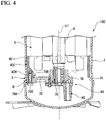
FIG. 4 is an enlarged cross sectional view of a main part of a scroll compressor according to a second embodiment of the present invention. -
FIG. 5 is a view showing a modification example of a scroll compressor according to an embodiment of the present invention. -
FIG. 6 is a view showing another modification of a scroll compressor according to an embodiment of the present invention. -
FIG. 7 is a process diagram showing processes of a method for producing the scroll compressor according to an embodiment of the present invention. - A
scroll compressor 100 according to a first embodiment of the present invention will be described with reference to the drawings. As shown inFIG. 1 , thescroll compressor 100 includes a housing 1 forming the outer shape of the device, and a drive unit 3 (an electric motor 3) provided in the housing 1, arotary shaft 4 rotationally driven by thedrive unit 3, a compression unit 2 (a scroll compressor body 2) driven by a rotation of therotary shaft 4, a main bearing 9A and a sub bearing 9B rotatably supporting therotary shaft 4, aharness 40 fitted within the housing 1, and a fixed portion (a bolt B, seeFIG. 2 ) configured to fix the sub bearing 9B to theharness 40. - The
compression unit 2 and thedrive unit 3 are connected to each other by therotary shaft 4 extending along anaxis 01. That is, rotational energy by thedrive unit 3 is transmitted immediately to thecompression unit 2 through therotary shaft 4. Thecompression unit 2 compresses a working fluid by this rotational energy and discharges it to the outside in a high pressure state. The working fluid in a high pressure state is used, for example, as a refrigerant in air conditioners and the like. Hereinafter, the configuration of each element will be described in detail. - The housing 1 is provided with a
suction pipe 11 for sucking a refrigerant gas as the working fluid from the outside, and adischarge pipe 12 for discharging the refrigerant gas that is in a high pressure state in adischarge chamber 67 after being compressed by thecompression unit 2. - The
rotary shaft 4 has a columnar shape centering on theaxis 01. Therotary shaft 4 rotatably supported within the housing 1 by the main bearing 9A provided at an end portion (first end portion) on one side of therotary shaft 4 in an axis O1 direction and the sub bearing 9B provided at the other end portion (second end portion) on the other side of therotary shaft 4 which is the opposite side in the axis O1 direction when viewed from the main bearing 9A. The main bearing 9A has a main bearingbody 75 which rotatably supports therotary shaft 4. - In the one end portion on one side of the
rotary shaft 4, aneccentric shaft 5 having a columnar shape and centering on aneccentric axis 02 that is different from the axis O1 is provided at an offset (eccentric) position with respect to the axis O1. Theeccentric axis 02 is parallel to the axis O1. Theeccentric shaft 5 has a columnar shape protruding from the end portion of therotary shaft 4 toward the one side in the axis O1 direction. Accordingly, in a state in which therotary shaft 4 is rotating about theaxis 01, theeccentric shaft 5 revolves around theaxis 01 of therotary shaft 4. - The main bearing 9A is provided with an Oldham
ring 91 for restricting a rotation (a rotation about the eccentric axis 02) of an orbitingscroll 7. Although the details are not shown, the Oldhamring 91 has projections that are fitted in a groove formed in anend plate 71 of theorbiting scroll 7. - The
compression unit 2 includes afixed scroll 6 and theorbiting scroll 7. Adischarge cover 8 is a member having a substantially disc shape and partitioning a space inside the housing 1 in the axis O1 direction; and at a central portion of thedischarge cover 8, adischarge port 68 which communicates the refrigerant gas after compression to the above thedischarge chamber 67 and adischarge valve 66 for preventing backflow of the refrigerant from the high pressure side are provided. - The
fixed scroll 6 is a member having a substantially disc shape and fixed inside the housing 1. The orbitingscroll 7 faces thefixed scroll 6 from the axis O1 direction to form a compression chamber C therebetween. More particularly, thefixed scroll 6 includes anend plate 61 having a disc shape, and afixed wrap 62 erected on a surface of the other side in the axis O1 direction of theend plate 61 from the one side toward the other side in the axis O1 direction. Theend plate 61 extends along a plane substantially perpendicular to the axis O1. The fixedwrap 62 is a wall body which is formed in a spiral shape when viewed from the axis O1 direction. More specifically, the fixedwrap 62 is formed in a plate-like member that is wound about a center of theend plate 61. As an example, the fixedwrap 62 may desirably be configured to form an involute curve centering on the axis O1 when viewed from theaxis 01 direction. - On an outer side in radial direction of the fixed
wrap 62, an outerperipheral wall 63 extending in a tubular shape along an outer periphery of theend plate 61 is formed. Further, on an edge at the other side in the axis O1 direction of the outerperipheral wall 63, aflange 64 having an annular shape and extending outward in a radial direction is provided. The fixedscroll 6 is fixed to themain bearing 9A by bolts or the like via theflange 64. Furthermore, a fixedscroll discharge port 65 is formed in a center portion of the spiral of the fixedscroll 6 is. - The
orbiting scroll 7 includes theend plate 71 having the disc shape, and the orbitingwrap 72 having a spiral shape and provided on a surface on one side in the axis O1 direction in theend plate 71. The orbitingwrap 72 may also desirably be configured to form an involute curve centering on theaxis 02. - Furthermore, the orbiting
wrap 72 faces the fixedwrap 62 from the axis O1 direction and is disposed so as to overlap each other in a direction intersecting with the axis O1. In other words, the fixedwrap 62 and the orbitingwrap 72 are engaged with each other. In such engaging state, a predetermined space is formed between the fixedwrap 62 and the orbitingwrap 72. The volume of this space varies while the orbitingwrap 72 orbits. Thereby, it is possible to compress the refrigerant gas. - The
orbiting scroll 7 configured as described above is connected to one side in theaxis 01 direction of the aboverotary shaft 4 via abushing assembly 10. Aboss 73 having a cylindrical shape is formed on a surface at the other side in theaxis 01 direction of theend plate 71 of the orbitingwrap 72. A central axis of theboss 73 is coaxial with theaxis 02. Theeccentric shaft 5 formed on therotary shaft 4 is fitted into an internal space of theboss 73 from the axis O1 direction through thebushing assembly 10. - In addition, lubricant oil is supplied to the rotary shaft 4 (the eccentric shaft 5) from a
lubrication pump 80. After lubricating a portion between thebush 101 of thebushing assembly 10 and the bearing 74 of theorbiting scroll 7, the lubricating oil is collected downwardly in the housing 1. - Next, a detail structure of the
sub bearing 9B will be described with reference toFIG. 2 orFIG. 3 . As shown in the figures, the sub bearing 9B includes asub-bearing body 76, aholder 78 having a tubular shape and supporting thesub-bearing body 76 from the outer peripheral side of thesub-bearing body 76, and a plurality (three) ofarms 79 that extends radially so that theholder 78 is provided as a center. - The
holder 78 is provided at a position substantially coaxial with theaxis 01. Thearm 79 is a rod-like member that connects an innerperipheral surface 1A of the housing 1 and an outer peripheral surface of theholder 78. The threearms 79 in the present embodiment have substantially the same shape and size with each other. Furthermore, the end portion (an outerperipheral end 79A) at the outer side in the radial direction of thearm 79 has afirst hole 79H through which a fastening bolt B is inserted. In addition, thefirst hole 79H has an inner diameter that is slightly larger than a shaft diameter of the fastening bolt B. That is, when the fastening bolt B is inserted into thefirst hole 79H, a slight gap is formed between the outer peripheral surface of the fastening bolt B and an inner peripheral surface of thefirst hole 79H. - The
sub bearing 9B configured as described above is fixed to the housing 1 via theharness 40. Theharness 40 is a member having a substantially ring shape centering on theaxis 01. An outer diameter of theharness 40 is substantially set equal to or slightly smaller than an inner diameter of the housing 1. - The
harness 40 is fixed to the inner peripheral surface of the housing 1 by shrink fitting. More specifically, theharness 40 is fixed to the housing 1 by the following method (a method for producing the scroll compressor). The method includes an assembling process, a shrink fitting process, and a fixation process. In the assembling process, the electric motor 3 (the drive unit 3), therotary shaft 4, the scroll compressor body 2 (the compression unit 2), and themain bearing 9A are housed within the housing 1. Then, in the shrink fitting process, theharness 40 is fixed by shrink fitting with respect to the inner peripheral surface of the housing 1. - More specifically, in a shrink fitting process, the housing 1 is thermally expanded by heating by a heat source, and the inner diameter of the housing 1 is expanded. In a state where the inner diameter of the housing 1 is expanded, the
harness 40 is fitted to the inside of the housing 1. Thereafter, by removing heat of the housing 1, the housing 1 shrinks to restore the initial size. As the result, theharness 40 is firmly fixed on the inner peripheral side of the housing 1. Thereafter, the sub bearing 9B is fixed to theharness 40 by the bolt B as the fixed portion described later (the fixing process). - Here, the
harness 40 is formed line-symmetrically with respect to an object axis Os extending in a horizontal plane that intersects the axis O1. Further, when viewed from the axis O1 direction, an outer peripheral portion of theharness 40 is cut out at four portions and the four portions are respectively defined as a cutout portion 41. These four cutout portions 41 are respectively defined as afirst cutout 41A and asecond cutout 41B which are line symmetrical with respect to the object axis Os described above. Thefirst cutout 41A has a curved edge that curves radially inward from the outer peripheral edge (outer peripheral side) of theharness 40, when viewed from the axis O1 direction. In addition, thesecond cutout 41B is a straight edge forming a chord of theharness 40. - Furthermore, the
harness 40 according to the present embodiment has a plurality ofsecond holes 40H for fixing thearms 79 of thesub bearing 9B. More specifically, each of thesecond holes 40H is formed at a position corresponding to thefirst hole 79H formed in each of the three thearms 79, when viewed from the axis O1 direction. After corresponding thefirst hole 79H formed in thearm 79 to thesecond hole 40H of theharness 40 fixed to the inner peripheral surface of the housing 1, the bolt B is inserted so as to penetrate both thefirst hole 79H and thesecond hole 40H and is fastened by a nut or the like. In addition, in the state of being fixed in the housing 1, theharness 40 is in a state of substantially abutting the drive unit 3 (the electric motor 3) described above from the axis O1 direction. - Incidentally, as described above, an inner diameter of the
first hole 79H formed in the arm 79 (thesub bearing 9B) is slightly larger than the shaft diameter of the bolt B. Thus, in the stage before completely fastening the bolt B, the sub bearing 9B has a room for slightly pivots around the axis O1 with respect to theharness 40. By using this room, a central axis of thesub bearing 9B (the sub-bearing body 76) is possible to be matched with respect to the axis O1 of the housing 1 (the rotary shaft 4). In other words, the sub bearing 9B is capable of carrying out centering with respect the axis O1. - Next, the operation of the
scroll compressor 100 according to the present embodiment will be described. To start the operation of thescroll compressor 100, first by energizing the above drive unit 3 (the electric motor 3), therotary shaft 4 is rotationally driven about the axis O1. - In association with the rotation of the
rotary shaft 4, theeccentric shaft 5 described above revolves around the axis O1, and theorbiting scroll 7 attached thereto orbits the axis O1 as the center. Here, the rotation of theorbiting scroll 7 is restricted by theOldham ring 91 described above. Therefore, theorbiting scroll 7 performs a circular motion (orbits) along a locus drawn by theeccentric axis 02 so that the axis O1 of therotary shaft 4 is provided as a center. Along with this orbiting, the orbitingwrap 72 of theorbiting scroll 7 repeats a continuous relative movement relative to the fixedwrap 62 of the fixedscroll 6. Due to this relative movement, the volume of the compression chamber C formed between the fixedwrap 62 and orbitingwrap 72 varies with time. - Although not shown in detail, first, during orbiting of the
orbiting scroll 7, the refrigerant gas as the working fluid is introduced into the compression chamber C from an opening created at an outside in the radial direction of the orbiting wrap 72 (and the fixed wrap 62). In association with the orbiting of theorbiting scroll 7, the opening described above is closed. Thus, the refrigerant gas is confined within the compression chamber C. Subsequently, as theorbiting scroll 7 still orbits, the refrigerant gas moves radially inward (i.e., theeccentric axis 02 side). At this time, since the orbitingwrap 72 and the fixedwrap 62 are formed in the spiral shape as described above, the volume of the compression chamber C formed by the both is contracted gradually toward the inner side in the radial direction. As the result, the refrigerant gas is compressed. Eventually, in the vicinity of the center portion of the orbiting scroll 7 (or the fixed scroll 6), the refrigerant gas reaches the maximum pressure, and then is supplied to the outside through the above fixedscroll discharge port 65 and thedischarge pipe 12 of the housing 1. - Here, as described above, when the
arm 79 in the sub bearing 9B is directly fixed to the inner peripheral surface of the housing 1 by for example welding, thearm 79 is subjected to a load acting inwardly or outwardly in the radial direction with a sinusoidal increase and decrease by reaction force when compressing the refrigerant gas and moment of the member such as a balance weight for adjusting balance during rotation. - When such load is continuously added, the fixation between the
arm 79 and the housing 1 is weakened and the operation of the device may be hindered. However, in thescroll compressor 100 according to the present embodiment, the arm 79 (thesub bearing 9B) is fixed to the housing 1 via theharness 40 as described above. Particularly, theharness 40 is fixed by shrink fitting with respect to the inner peripheral surface of the housing 1. That is, the outer peripheral surface of theharness 40 and the inner peripheral surface of the housing 1 abut to each other and are held in a state of interference fit. Thus, it possible to fix firmly and stably the arm 79 (thesub bearing 9B) to the innerperipheral surface 1A of the housing 1. Therefore, even when vibration is propagated from the scroll compressor body to the arm, it is possible to substantially eliminate the possibility of falling the arm and a harness out from a housing. - Furthermore, according to the above-described structure, the inner diameter of the
first hole 79H formed the arm 79 (thesub bearing 9B) is slightly larger relative the shaft diameter of the bolt B. That is, in the stage before tightening complete the bolt B, thesub bearing 9B for theharness 40, there is room for slightly pivots around the axis O1. By using this room, the central axis of thesub bearing 9B (the sub-bearing body 76) is matched against the axis O1 of the housing 1 (the rotary shaft 4). In other words, it is possible to center the sub bearing 9B against the axis O1. - The first embodiment of the present invention has been described with reference to the drawings. The above embodiment is merely an example, and thus, various modifications and the like can be applied to this.
- Next, a second embodiment of the present invention will be described with reference to
FIG. 4 . As shown in the figure, in the scroll compressor 200 according to the present embodiment, the shape of thearm 79 in the sub bearing 9B and the shape of theharness 40 are different from the first embodiment. - That is, in the present embodiment, a region including the outer
peripheral end 79A of thearm 79 is formed thinner than other portions of the outerperipheral end 79A, and is defined as athin portion 79B. Specifically, an end face at one side in the axis O1 direction of the arm 79 (thedrive unit 3 side) has a counterbore that slightly deepens toward the other side in theaxis 01 direction. Thus, a step is formed between thethin portion 79B and the other portions of the arm 79 (the radially inward portion with respect to the axis O1). - In such
thin portion 79B, a shim S having an extremely thin plate-like shape is disposed as needed. By the shim S being interposed, it is possible to easily carry out alignment (the alignment in the axis O1 direction) of the sub bearing 9B with respect to theharness 40. In particular, when theharness 40 is fixed to the innerperipheral surface 1A of the housing 1 by shrink fitting, it is conceivable that the precise alignment of theharness 40 in the axis O1 direction is difficult. That is, by the disposition of theharness 40 in a slightly deviated position in the axis O1 direction with respect to the housing 1, there may be a possibility in that the positional deviation of the sub bearing 9B in theaxis 01 direction is occurred. - However, by disposing the shim S between the sub bearing 9B and the
harness 40 as described in the above, such deviation is offset and it is possible to optimize the position of the sub bearing 9B in the axis O1 direction. In addition, as the shim S, a plurality types of shims in different thickness is prepared and it is preferable to appropriately select and used a properly shim S according to the deviation amount between theharness 40 and thesub bearing 9B. - Furthermore, in the present embodiment, a size in the radial direction (thickness) in a region at one side in the axis O1 direction of the
harness 40 is smaller than that in the first embodiment. More particularly, by setting a distance in the radial direction between the outer peripheral surface of theharness 40 and the inner peripheral surface thereof smaller than that in the first embodiment, aconstricted part 40C are formed. According to theconstricted part 40C, it is possible to ensure a larger gap between an inner peripheral surface 40A of theharness 40 and thedrive unit 3. - Here, in the
main bearing 9A and thesub bearing 9B described above, lubricant oil is continuously supplied by thelubrication pump 80. The lubricant oil that has finished lubricating themain bearing 9A, the sub bearing 9B flows downward at below the housing 1 (i.e., the other side in the axis O1 direction), and is stored. - At this time, if the gap between the
harness 40 and thedrive unit 3 is not large enough, there is a possibility of affecting a flow of the lubricant oil. However, in the present embodiment, since theconstricted part 40C is formed in theharness 40, it is possible to reduce the possibility in that theharness 40 affects a flow state of the lubricant oil. - In addition, in each embodiment described above, the end face at one side in the axis O1 direction of the
harness 40 abuts thedrive unit 3. However, the aspect of theharness 40 is not limited thereto, and for example, as shown inFIG. 5 , a gap along the axis O1 direction may be formed between theharness 40 and thedrive unit 3. In this case, it is possible to further reduce the possibility in that theharness 40 affects a flow state of the lubricant oil. - Further, in each of the embodiments described above, the sub bearing 9B has been described with three
arms 79. However, the aspect of the sub bearing 9B is not limited thereto, and for example, as shown inFIG. 6 , fourarms 79 extending in a radial fashion in the radial direction from theholder 78 may be provided. In this case, it is desirable to form foursecond holes 40H in theharness 40 so as to corresponding to the fourarms 79. - According to the scroll compressor of the present invention, it is possible to realize stable operation for a long-term.
-
- 1 ... Housing
- 2 ... Compression unit
- 3 ... Drive unit (electric motor)
- 4 ... Rotary shaft
- 5 ... Eccentric shaft
- 6 ... Fixed scroll
- 7 ... Orbiting scroll
- 8 ... Discharge cover
- 9A ... Main bearing
- 9B ... Sub bearing
- 10 ... Bush assembly
- 11 ... Suction piping
- 12 ... Discharge piping
- 40 ... Harness
- 61 ... End plate
- 62 ... Fixed wrap
- 63 ... Outer peripheral wall
- 64 ... Flange
- 65 ... Fixed scroll discharge port
- 66 ... Discharge valve
- 67 ... Discharge chamber
- 68 ... Discharge port
- 71 ... End plate
- 72 ... Orbiting wrap
- 73 ... Boss
- 74 ... Bearing
- 75 ... Main bearing body
- 76 ... Sub bearing body
- 79 ... Arm
- 80 ... Lubrication pump
- 91 ... Oldham ring
- 92 ... Thrust bearing
- 93 ... Oil drain hole
- 100 ... Scroll compressor
- 101 ... Bush
- C ... Compression chamber
- H1 ... Welding-use opening
- H2, H21, H22 ... Hole
- O1 ... Axis
- O2 ... Eccentric axis
- W ... Welded portion
Claims (4)
- A scroll compressor comprising:an electric motor;a rotary shaft rotationally driven about an axis thereof by the electric motor;a scroll compressor body driven by a rotation of the rotary shaft;a main bearing rotatably supporting the rotary shaft between the electric motor and the scroll compressor body;a sub bearing supporting the rotary shaft at opposite side of the main bearing of the electric motor, and provided with a plurality of arms at intervals in a peripheral direction of the rotary shaft, the plurality of arms extending along a radial direction of the rotary shaft;a housing having a tubular shape extending along the axis, and housing the electric motor, the rotary shaft, the scroll compressor body, the main bearing, and the sub bearing;a harness having a ring shape and fitted onto an inner peripheral surface of the housing; anda fixed portion in which the arms of the sub bearing are fixed to the harness.
- The scroll compressor according to Claim 1, wherein
the fixed portion is a fastening bolt that is inserted through a first hole formed in the arm and a second hole formed in the harness, and
an inner diameter of the first hole is larger than an outer diameter of the fastening bolt. - The scroll compressor according to Claim 1 or 2, further comprises:a shim for an alignment of each arm in an axial direction by interposing the shim between the arm and the harness.
- A method for producing a scroll compressor including:an electric motor;a rotary shaft rotationally driven about an axis thereof by the electric motor;a scroll compressor body driven by a rotation of the rotary shaft;a main bearing rotatably supporting the rotary shaft between the electric motor and the scroll compressor body;a sub bearing supporting the rotary shaft at opposite side of the main bearing of the electric motor, and provided with a plurality of arms at intervals in a peripheral direction of the rotary shaft, the plurality of arms extending along a radial direction of the rotary shaft;a housing having a tubular shape extending along the axis, and housing the electric motor, the rotary shaft, the scroll compressor body, the main bearing, and the sub bearing;a harness having a ring shape and fitted onto an inner peripheral surface of the housing; anda fixed portion in which the arms of the sub bearing are fixed to the harness,wherein the method comprises:an assembling process that houses the electric motor, the rotary shaft, the scroll compressor body, the main bearing within the housing;a shrink fitting process that fixes the harness to the inner peripheral surface of the housing by shrink fitting; anda fixing process that fixes the sub bearing to the harness via the fixed portion.
Applications Claiming Priority (2)
| Application Number | Priority Date | Filing Date | Title |
|---|---|---|---|
| JP2015217463A JP2017089427A (en) | 2015-11-05 | 2015-11-05 | Scroll compressor, and method of manufacturing scroll compressor |
| PCT/JP2016/080210 WO2017077826A1 (en) | 2015-11-05 | 2016-10-12 | Scroll compressor and method for producing scroll compressor |
Publications (3)
| Publication Number | Publication Date |
|---|---|
| EP3315777A1 true EP3315777A1 (en) | 2018-05-02 |
| EP3315777A4 EP3315777A4 (en) | 2018-08-22 |
| EP3315777B1 EP3315777B1 (en) | 2019-10-23 |
Family
ID=58661979
Family Applications (1)
| Application Number | Title | Priority Date | Filing Date |
|---|---|---|---|
| EP16861893.2A Active EP3315777B1 (en) | 2015-11-05 | 2016-10-12 | Scroll compressor and method for producing scroll compressor |
Country Status (4)
| Country | Link |
|---|---|
| EP (1) | EP3315777B1 (en) |
| JP (1) | JP2017089427A (en) |
| CN (1) | CN107923396A (en) |
| WO (1) | WO2017077826A1 (en) |
Cited By (1)
| Publication number | Priority date | Publication date | Assignee | Title |
|---|---|---|---|---|
| DE102021206432A1 (en) | 2021-06-22 | 2022-12-22 | Brose Fahrzeugteile SE & Co. Kommanditgesellschaft, Würzburg | scroll machine |
Families Citing this family (2)
| Publication number | Priority date | Publication date | Assignee | Title |
|---|---|---|---|---|
| CN111237188B (en) * | 2018-11-29 | 2024-04-26 | 谷轮环境科技(苏州)有限公司 | Scroll compressor and positioning method for non-orbiting scroll part of scroll compressor |
| CN117642555B (en) * | 2021-08-05 | 2024-05-28 | 大金工业株式会社 | Scroll compressor and refrigeration cycle device |
Family Cites Families (20)
| Publication number | Priority date | Publication date | Assignee | Title |
|---|---|---|---|---|
| JP2697278B2 (en) * | 1990-10-05 | 1998-01-14 | 三菱電機株式会社 | Manufacturing method of scroll compressor |
| JP3198576B2 (en) * | 1992-01-31 | 2001-08-13 | 松下電器産業株式会社 | Scroll compressor |
| JPH0842471A (en) * | 1994-07-29 | 1996-02-13 | Sanyo Electric Co Ltd | Scroll compressor |
| JPH08312550A (en) * | 1995-05-19 | 1996-11-26 | Fujitsu General Ltd | Scroll compressor |
| JPH1047269A (en) * | 1996-08-01 | 1998-02-17 | Mitsubishi Electric Corp | Scroll compressor |
| JP3550940B2 (en) * | 1997-04-24 | 2004-08-04 | 三菱電機株式会社 | Fluid machinery |
| JP2000104691A (en) * | 1998-09-25 | 2000-04-11 | Sanyo Electric Co Ltd | Scroll compressor auxiliary bearing |
| JP2000274362A (en) * | 1999-03-25 | 2000-10-03 | Hitachi Ltd | Compressor and assembly method thereof |
| JP2002339887A (en) * | 2001-05-17 | 2002-11-27 | Matsushita Electric Ind Co Ltd | Hermetic compressor |
| US7094043B2 (en) * | 2002-09-23 | 2006-08-22 | Tecumseh Products Company | Compressor having counterweight shield |
| JP2004176549A (en) * | 2002-11-25 | 2004-06-24 | Fujitsu General Ltd | Manufacturing method of hermetic compressor |
| JP4376554B2 (en) * | 2003-06-12 | 2009-12-02 | パナソニック株式会社 | Scroll compressor |
| JP4440564B2 (en) * | 2003-06-12 | 2010-03-24 | パナソニック株式会社 | Scroll compressor |
| US8147229B2 (en) * | 2005-01-20 | 2012-04-03 | Tecumseh Products Company | Motor-compressor unit mounting arrangement for compressors |
| JP5114710B2 (en) * | 2007-10-16 | 2013-01-09 | 株式会社前川製作所 | Hermetic scroll compressor and method for assembling the same |
| JP2009228441A (en) * | 2008-03-19 | 2009-10-08 | Sanyo Electric Co Ltd | Scroll compressor |
| US8342795B2 (en) * | 2008-04-24 | 2013-01-01 | Emerson Climate Technologies, Inc. | Support member for optimizing dynamic load distribution and attenuating vibration |
| US9080570B2 (en) * | 2009-09-25 | 2015-07-14 | Toshiba Carrier Corporation | Hermetic compressor and refrigeration cycle equipment using the same |
| JP5984787B2 (en) * | 2013-12-04 | 2016-09-06 | 三菱電機株式会社 | Scroll compressor |
| CN104165142B (en) * | 2014-08-01 | 2017-02-22 | 广东美芝制冷设备有限公司 | Rotary compressor |
-
2015
- 2015-11-05 JP JP2015217463A patent/JP2017089427A/en active Pending
-
2016
- 2016-10-12 CN CN201680043785.8A patent/CN107923396A/en active Pending
- 2016-10-12 WO PCT/JP2016/080210 patent/WO2017077826A1/en not_active Ceased
- 2016-10-12 EP EP16861893.2A patent/EP3315777B1/en active Active
Cited By (1)
| Publication number | Priority date | Publication date | Assignee | Title |
|---|---|---|---|---|
| DE102021206432A1 (en) | 2021-06-22 | 2022-12-22 | Brose Fahrzeugteile SE & Co. Kommanditgesellschaft, Würzburg | scroll machine |
Also Published As
| Publication number | Publication date |
|---|---|
| WO2017077826A1 (en) | 2017-05-11 |
| EP3315777B1 (en) | 2019-10-23 |
| JP2017089427A (en) | 2017-05-25 |
| CN107923396A (en) | 2018-04-17 |
| EP3315777A4 (en) | 2018-08-22 |
Similar Documents
| Publication | Publication Date | Title |
|---|---|---|
| KR102027695B1 (en) | Scroll compressor | |
| US8342795B2 (en) | Support member for optimizing dynamic load distribution and attenuating vibration | |
| JP2001221171A (en) | Scroll machine | |
| EP2913531B1 (en) | Scroll compressor with balance weight | |
| EP3447296A1 (en) | Compressor | |
| US20130251551A1 (en) | Compressor shell with multiple diameters | |
| EP3315777B1 (en) | Scroll compressor and method for producing scroll compressor | |
| JP4594265B2 (en) | Scroll type fluid machine | |
| EP3339644A1 (en) | Scroll compressor and method for producing scroll compressor | |
| EP3308027B1 (en) | Ring weld blocker in discharge check valve | |
| EP3534005B1 (en) | Scroll compressor and method for producing same | |
| EP3492743B1 (en) | Scroll-type fluid machine and method for assembling same | |
| CN107882738B (en) | Compressor with a compressor housing having a plurality of compressor blades | |
| CN112005013A (en) | Scroll compressor and method of manufacturing the same | |
| JP2017145806A (en) | Scroll compressor | |
| JP4045567B2 (en) | Compressor and its assembly method | |
| JP4415178B2 (en) | Scroll fluid machine and assembly method thereof | |
| JP5430208B2 (en) | Sealed fluid machinery | |
| EP4534845A1 (en) | Scroll compressor and method for assembling scroll compressor | |
| KR940006866B1 (en) | Axial fluid compressor | |
| EP3396166A1 (en) | Rotary machine | |
| US20160369799A1 (en) | Separator plate with inlet curve | |
| EP2383481A2 (en) | Radial needle bearing | |
| JP4748585B2 (en) | Manufacturing method of scroll compressor | |
| JPH041494A (en) | Hydraulic compressor and assembling method thereof |
Legal Events
| Date | Code | Title | Description |
|---|---|---|---|
| STAA | Information on the status of an ep patent application or granted ep patent |
Free format text: STATUS: THE INTERNATIONAL PUBLICATION HAS BEEN MADE |
|
| PUAI | Public reference made under article 153(3) epc to a published international application that has entered the european phase |
Free format text: ORIGINAL CODE: 0009012 |
|
| STAA | Information on the status of an ep patent application or granted ep patent |
Free format text: STATUS: REQUEST FOR EXAMINATION WAS MADE |
|
| 17P | Request for examination filed |
Effective date: 20180126 |
|
| AK | Designated contracting states |
Kind code of ref document: A1 Designated state(s): AL AT BE BG CH CY CZ DE DK EE ES FI FR GB GR HR HU IE IS IT LI LT LU LV MC MK MT NL NO PL PT RO RS SE SI SK SM TR |
|
| AX | Request for extension of the european patent |
Extension state: BA ME |
|
| A4 | Supplementary search report drawn up and despatched |
Effective date: 20180723 |
|
| RIC1 | Information provided on ipc code assigned before grant |
Ipc: F01C 21/02 20060101ALI20180717BHEP Ipc: F01C 21/00 20060101ALI20180717BHEP Ipc: F04C 23/00 20060101ALI20180717BHEP Ipc: F04C 29/02 20060101ALI20180717BHEP Ipc: F04C 18/02 20060101AFI20180717BHEP Ipc: F04C 29/00 20060101ALI20180717BHEP |
|
| DAV | Request for validation of the european patent (deleted) | ||
| DAX | Request for extension of the european patent (deleted) | ||
| GRAP | Despatch of communication of intention to grant a patent |
Free format text: ORIGINAL CODE: EPIDOSNIGR1 |
|
| STAA | Information on the status of an ep patent application or granted ep patent |
Free format text: STATUS: GRANT OF PATENT IS INTENDED |
|
| RIC1 | Information provided on ipc code assigned before grant |
Ipc: F04C 23/00 20060101ALI20190405BHEP Ipc: F04C 18/02 20060101AFI20190405BHEP Ipc: F04C 29/00 20060101ALI20190405BHEP Ipc: F04C 29/02 20060101ALI20190405BHEP Ipc: F01C 21/02 20060101ALI20190405BHEP Ipc: F01C 21/00 20060101ALI20190405BHEP |
|
| INTG | Intention to grant announced |
Effective date: 20190509 |
|
| GRAS | Grant fee paid |
Free format text: ORIGINAL CODE: EPIDOSNIGR3 |
|
| GRAA | (expected) grant |
Free format text: ORIGINAL CODE: 0009210 |
|
| STAA | Information on the status of an ep patent application or granted ep patent |
Free format text: STATUS: THE PATENT HAS BEEN GRANTED |
|
| AK | Designated contracting states |
Kind code of ref document: B1 Designated state(s): AL AT BE BG CH CY CZ DE DK EE ES FI FR GB GR HR HU IE IS IT LI LT LU LV MC MK MT NL NO PL PT RO RS SE SI SK SM TR |
|
| REG | Reference to a national code |
Ref country code: GB Ref legal event code: FG4D |
|
| REG | Reference to a national code |
Ref country code: CH Ref legal event code: EP |
|
| REG | Reference to a national code |
Ref country code: IE Ref legal event code: FG4D |
|
| REG | Reference to a national code |
Ref country code: DE Ref legal event code: R096 Ref document number: 602016023127 Country of ref document: DE |
|
| REG | Reference to a national code |
Ref country code: AT Ref legal event code: REF Ref document number: 1193936 Country of ref document: AT Kind code of ref document: T Effective date: 20191115 |
|
| REG | Reference to a national code |
Ref country code: NL Ref legal event code: MP Effective date: 20191023 |
|
| REG | Reference to a national code |
Ref country code: LT Ref legal event code: MG4D |
|
| PG25 | Lapsed in a contracting state [announced via postgrant information from national office to epo] |
Ref country code: LV Free format text: LAPSE BECAUSE OF FAILURE TO SUBMIT A TRANSLATION OF THE DESCRIPTION OR TO PAY THE FEE WITHIN THE PRESCRIBED TIME-LIMIT Effective date: 20191023 Ref country code: SE Free format text: LAPSE BECAUSE OF FAILURE TO SUBMIT A TRANSLATION OF THE DESCRIPTION OR TO PAY THE FEE WITHIN THE PRESCRIBED TIME-LIMIT Effective date: 20191023 Ref country code: NL Free format text: LAPSE BECAUSE OF FAILURE TO SUBMIT A TRANSLATION OF THE DESCRIPTION OR TO PAY THE FEE WITHIN THE PRESCRIBED TIME-LIMIT Effective date: 20191023 Ref country code: LT Free format text: LAPSE BECAUSE OF FAILURE TO SUBMIT A TRANSLATION OF THE DESCRIPTION OR TO PAY THE FEE WITHIN THE PRESCRIBED TIME-LIMIT Effective date: 20191023 Ref country code: GR Free format text: LAPSE BECAUSE OF FAILURE TO SUBMIT A TRANSLATION OF THE DESCRIPTION OR TO PAY THE FEE WITHIN THE PRESCRIBED TIME-LIMIT Effective date: 20200124 Ref country code: NO Free format text: LAPSE BECAUSE OF FAILURE TO SUBMIT A TRANSLATION OF THE DESCRIPTION OR TO PAY THE FEE WITHIN THE PRESCRIBED TIME-LIMIT Effective date: 20200123 Ref country code: PL Free format text: LAPSE BECAUSE OF FAILURE TO SUBMIT A TRANSLATION OF THE DESCRIPTION OR TO PAY THE FEE WITHIN THE PRESCRIBED TIME-LIMIT Effective date: 20191023 Ref country code: FI Free format text: LAPSE BECAUSE OF FAILURE TO SUBMIT A TRANSLATION OF THE DESCRIPTION OR TO PAY THE FEE WITHIN THE PRESCRIBED TIME-LIMIT Effective date: 20191023 Ref country code: BG Free format text: LAPSE BECAUSE OF FAILURE TO SUBMIT A TRANSLATION OF THE DESCRIPTION OR TO PAY THE FEE WITHIN THE PRESCRIBED TIME-LIMIT Effective date: 20200123 Ref country code: PT Free format text: LAPSE BECAUSE OF FAILURE TO SUBMIT A TRANSLATION OF THE DESCRIPTION OR TO PAY THE FEE WITHIN THE PRESCRIBED TIME-LIMIT Effective date: 20200224 |
|
| PG25 | Lapsed in a contracting state [announced via postgrant information from national office to epo] |
Ref country code: IS Free format text: LAPSE BECAUSE OF FAILURE TO SUBMIT A TRANSLATION OF THE DESCRIPTION OR TO PAY THE FEE WITHIN THE PRESCRIBED TIME-LIMIT Effective date: 20200224 Ref country code: RS Free format text: LAPSE BECAUSE OF FAILURE TO SUBMIT A TRANSLATION OF THE DESCRIPTION OR TO PAY THE FEE WITHIN THE PRESCRIBED TIME-LIMIT Effective date: 20191023 Ref country code: HR Free format text: LAPSE BECAUSE OF FAILURE TO SUBMIT A TRANSLATION OF THE DESCRIPTION OR TO PAY THE FEE WITHIN THE PRESCRIBED TIME-LIMIT Effective date: 20191023 |
|
| PG25 | Lapsed in a contracting state [announced via postgrant information from national office to epo] |
Ref country code: AL Free format text: LAPSE BECAUSE OF FAILURE TO SUBMIT A TRANSLATION OF THE DESCRIPTION OR TO PAY THE FEE WITHIN THE PRESCRIBED TIME-LIMIT Effective date: 20191023 |
|
| REG | Reference to a national code |
Ref country code: DE Ref legal event code: R097 Ref document number: 602016023127 Country of ref document: DE |
|
| PG2D | Information on lapse in contracting state deleted |
Ref country code: IS |
|
| PG25 | Lapsed in a contracting state [announced via postgrant information from national office to epo] |
Ref country code: CZ Free format text: LAPSE BECAUSE OF FAILURE TO SUBMIT A TRANSLATION OF THE DESCRIPTION OR TO PAY THE FEE WITHIN THE PRESCRIBED TIME-LIMIT Effective date: 20191023 Ref country code: RO Free format text: LAPSE BECAUSE OF FAILURE TO SUBMIT A TRANSLATION OF THE DESCRIPTION OR TO PAY THE FEE WITHIN THE PRESCRIBED TIME-LIMIT Effective date: 20191023 Ref country code: EE Free format text: LAPSE BECAUSE OF FAILURE TO SUBMIT A TRANSLATION OF THE DESCRIPTION OR TO PAY THE FEE WITHIN THE PRESCRIBED TIME-LIMIT Effective date: 20191023 Ref country code: DK Free format text: LAPSE BECAUSE OF FAILURE TO SUBMIT A TRANSLATION OF THE DESCRIPTION OR TO PAY THE FEE WITHIN THE PRESCRIBED TIME-LIMIT Effective date: 20191023 Ref country code: ES Free format text: LAPSE BECAUSE OF FAILURE TO SUBMIT A TRANSLATION OF THE DESCRIPTION OR TO PAY THE FEE WITHIN THE PRESCRIBED TIME-LIMIT Effective date: 20191023 Ref country code: IS Free format text: LAPSE BECAUSE OF FAILURE TO SUBMIT A TRANSLATION OF THE DESCRIPTION OR TO PAY THE FEE WITHIN THE PRESCRIBED TIME-LIMIT Effective date: 20200223 |
|
| REG | Reference to a national code |
Ref country code: AT Ref legal event code: MK05 Ref document number: 1193936 Country of ref document: AT Kind code of ref document: T Effective date: 20191023 |
|
| PLBE | No opposition filed within time limit |
Free format text: ORIGINAL CODE: 0009261 |
|
| STAA | Information on the status of an ep patent application or granted ep patent |
Free format text: STATUS: NO OPPOSITION FILED WITHIN TIME LIMIT |
|
| PG25 | Lapsed in a contracting state [announced via postgrant information from national office to epo] |
Ref country code: IT Free format text: LAPSE BECAUSE OF FAILURE TO SUBMIT A TRANSLATION OF THE DESCRIPTION OR TO PAY THE FEE WITHIN THE PRESCRIBED TIME-LIMIT Effective date: 20191023 Ref country code: SK Free format text: LAPSE BECAUSE OF FAILURE TO SUBMIT A TRANSLATION OF THE DESCRIPTION OR TO PAY THE FEE WITHIN THE PRESCRIBED TIME-LIMIT Effective date: 20191023 Ref country code: SM Free format text: LAPSE BECAUSE OF FAILURE TO SUBMIT A TRANSLATION OF THE DESCRIPTION OR TO PAY THE FEE WITHIN THE PRESCRIBED TIME-LIMIT Effective date: 20191023 |
|
| 26N | No opposition filed |
Effective date: 20200724 |
|
| PG25 | Lapsed in a contracting state [announced via postgrant information from national office to epo] |
Ref country code: AT Free format text: LAPSE BECAUSE OF FAILURE TO SUBMIT A TRANSLATION OF THE DESCRIPTION OR TO PAY THE FEE WITHIN THE PRESCRIBED TIME-LIMIT Effective date: 20191023 Ref country code: SI Free format text: LAPSE BECAUSE OF FAILURE TO SUBMIT A TRANSLATION OF THE DESCRIPTION OR TO PAY THE FEE WITHIN THE PRESCRIBED TIME-LIMIT Effective date: 20191023 |
|
| REG | Reference to a national code |
Ref country code: CH Ref legal event code: PL |
|
| PG25 | Lapsed in a contracting state [announced via postgrant information from national office to epo] |
Ref country code: LU Free format text: LAPSE BECAUSE OF NON-PAYMENT OF DUE FEES Effective date: 20201012 Ref country code: MC Free format text: LAPSE BECAUSE OF FAILURE TO SUBMIT A TRANSLATION OF THE DESCRIPTION OR TO PAY THE FEE WITHIN THE PRESCRIBED TIME-LIMIT Effective date: 20191023 |
|
| REG | Reference to a national code |
Ref country code: BE Ref legal event code: MM Effective date: 20201031 |
|
| PG25 | Lapsed in a contracting state [announced via postgrant information from national office to epo] |
Ref country code: BE Free format text: LAPSE BECAUSE OF NON-PAYMENT OF DUE FEES Effective date: 20201031 Ref country code: CH Free format text: LAPSE BECAUSE OF NON-PAYMENT OF DUE FEES Effective date: 20201031 Ref country code: LI Free format text: LAPSE BECAUSE OF NON-PAYMENT OF DUE FEES Effective date: 20201031 |
|
| PG25 | Lapsed in a contracting state [announced via postgrant information from national office to epo] |
Ref country code: IE Free format text: LAPSE BECAUSE OF NON-PAYMENT OF DUE FEES Effective date: 20201012 |
|
| PG25 | Lapsed in a contracting state [announced via postgrant information from national office to epo] |
Ref country code: TR Free format text: LAPSE BECAUSE OF FAILURE TO SUBMIT A TRANSLATION OF THE DESCRIPTION OR TO PAY THE FEE WITHIN THE PRESCRIBED TIME-LIMIT Effective date: 20191023 Ref country code: MT Free format text: LAPSE BECAUSE OF FAILURE TO SUBMIT A TRANSLATION OF THE DESCRIPTION OR TO PAY THE FEE WITHIN THE PRESCRIBED TIME-LIMIT Effective date: 20191023 Ref country code: CY Free format text: LAPSE BECAUSE OF FAILURE TO SUBMIT A TRANSLATION OF THE DESCRIPTION OR TO PAY THE FEE WITHIN THE PRESCRIBED TIME-LIMIT Effective date: 20191023 |
|
| PG25 | Lapsed in a contracting state [announced via postgrant information from national office to epo] |
Ref country code: MK Free format text: LAPSE BECAUSE OF FAILURE TO SUBMIT A TRANSLATION OF THE DESCRIPTION OR TO PAY THE FEE WITHIN THE PRESCRIBED TIME-LIMIT Effective date: 20191023 |
|
| REG | Reference to a national code |
Ref country code: DE Ref legal event code: R082 Ref document number: 602016023127 Country of ref document: DE Representative=s name: CBDL PATENTANWAELTE GBR, DE Ref country code: DE Ref legal event code: R082 Ref document number: 602016023127 Country of ref document: DE Representative=s name: CBDL PATENTANWAELTE EGBR, DE |
|
| PGFP | Annual fee paid to national office [announced via postgrant information from national office to epo] |
Ref country code: GB Payment date: 20250828 Year of fee payment: 10 |
|
| PGFP | Annual fee paid to national office [announced via postgrant information from national office to epo] |
Ref country code: FR Payment date: 20250908 Year of fee payment: 10 |
|
| PGFP | Annual fee paid to national office [announced via postgrant information from national office to epo] |
Ref country code: DE Payment date: 20250902 Year of fee payment: 10 |