EP3315746A1 - Fuel stabilization system and method of removing oxygen from fuel - Google Patents
Fuel stabilization system and method of removing oxygen from fuel Download PDFInfo
- Publication number
- EP3315746A1 EP3315746A1 EP17198186.3A EP17198186A EP3315746A1 EP 3315746 A1 EP3315746 A1 EP 3315746A1 EP 17198186 A EP17198186 A EP 17198186A EP 3315746 A1 EP3315746 A1 EP 3315746A1
- Authority
- EP
- European Patent Office
- Prior art keywords
- fuel
- accumulator
- heat
- downstream
- temperature
- Prior art date
- Legal status (The legal status is an assumption and is not a legal conclusion. Google has not performed a legal analysis and makes no representation as to the accuracy of the status listed.)
- Granted
Links
Images

Classifications
-
- B—PERFORMING OPERATIONS; TRANSPORTING
- B01—PHYSICAL OR CHEMICAL PROCESSES OR APPARATUS IN GENERAL
- B01D—SEPARATION
- B01D19/00—Degasification of liquids
- B01D19/0073—Degasification of liquids by a method not covered by groups B01D19/0005 - B01D19/0042
-
- C—CHEMISTRY; METALLURGY
- C10—PETROLEUM, GAS OR COKE INDUSTRIES; TECHNICAL GASES CONTAINING CARBON MONOXIDE; FUELS; LUBRICANTS; PEAT
- C10G—CRACKING HYDROCARBON OILS; PRODUCTION OF LIQUID HYDROCARBON MIXTURES, e.g. BY DESTRUCTIVE HYDROGENATION, OLIGOMERISATION, POLYMERISATION; RECOVERY OF HYDROCARBON OILS FROM OIL-SHALE, OIL-SAND, OR GASES; REFINING MIXTURES MAINLY CONSISTING OF HYDROCARBONS; REFORMING OF NAPHTHA; MINERAL WAXES
- C10G31/00—Refining of hydrocarbon oils, in the absence of hydrogen, by methods not otherwise provided for
- C10G31/06—Refining of hydrocarbon oils, in the absence of hydrogen, by methods not otherwise provided for by heating, cooling, or pressure treatment
-
- F—MECHANICAL ENGINEERING; LIGHTING; HEATING; WEAPONS; BLASTING
- F02—COMBUSTION ENGINES; HOT-GAS OR COMBUSTION-PRODUCT ENGINE PLANTS
- F02C—GAS-TURBINE PLANTS; AIR INTAKES FOR JET-PROPULSION PLANTS; CONTROLLING FUEL SUPPLY IN AIR-BREATHING JET-PROPULSION PLANTS
- F02C7/00—Features, components parts, details or accessories, not provided for in, or of interest apart form groups F02C1/00 - F02C6/00; Air intakes for jet-propulsion plants
- F02C7/22—Fuel supply systems
- F02C7/224—Heating fuel before feeding to the burner
-
- C—CHEMISTRY; METALLURGY
- C10—PETROLEUM, GAS OR COKE INDUSTRIES; TECHNICAL GASES CONTAINING CARBON MONOXIDE; FUELS; LUBRICANTS; PEAT
- C10G—CRACKING HYDROCARBON OILS; PRODUCTION OF LIQUID HYDROCARBON MIXTURES, e.g. BY DESTRUCTIVE HYDROGENATION, OLIGOMERISATION, POLYMERISATION; RECOVERY OF HYDROCARBON OILS FROM OIL-SHALE, OIL-SAND, OR GASES; REFINING MIXTURES MAINLY CONSISTING OF HYDROCARBONS; REFORMING OF NAPHTHA; MINERAL WAXES
- C10G2300/00—Aspects relating to hydrocarbon processing covered by groups C10G1/00 - C10G99/00
- C10G2300/20—Characteristics of the feedstock or the products
- C10G2300/201—Impurities
- C10G2300/202—Heteroatoms content, i.e. S, N, O, P
-
- F—MECHANICAL ENGINEERING; LIGHTING; HEATING; WEAPONS; BLASTING
- F02—COMBUSTION ENGINES; HOT-GAS OR COMBUSTION-PRODUCT ENGINE PLANTS
- F02C—GAS-TURBINE PLANTS; AIR INTAKES FOR JET-PROPULSION PLANTS; CONTROLLING FUEL SUPPLY IN AIR-BREATHING JET-PROPULSION PLANTS
- F02C7/00—Features, components parts, details or accessories, not provided for in, or of interest apart form groups F02C1/00 - F02C6/00; Air intakes for jet-propulsion plants
- F02C7/22—Fuel supply systems
- F02C7/232—Fuel valves; Draining valves or systems
-
- Y—GENERAL TAGGING OF NEW TECHNOLOGICAL DEVELOPMENTS; GENERAL TAGGING OF CROSS-SECTIONAL TECHNOLOGIES SPANNING OVER SEVERAL SECTIONS OF THE IPC; TECHNICAL SUBJECTS COVERED BY FORMER USPC CROSS-REFERENCE ART COLLECTIONS [XRACs] AND DIGESTS
- Y02—TECHNOLOGIES OR APPLICATIONS FOR MITIGATION OR ADAPTATION AGAINST CLIMATE CHANGE
- Y02T—CLIMATE CHANGE MITIGATION TECHNOLOGIES RELATED TO TRANSPORTATION
- Y02T50/00—Aeronautics or air transport
- Y02T50/60—Efficient propulsion technologies, e.g. for aircraft
Definitions
- the present disclosure relates to fuel systems, more specifically to fuel stabilization systems and methods.
- a fuel stabilization system for removing dissolved oxygen from fuel includes an accumulator disposed along a fuel line.
- the accumulator includes a fuel inlet and a fuel outlet and a heat source disposed in thermal communication with the fuel in or upstream of the fuel inlet of the accumulator to increase the temperature of the fuel within the accumulator.
- the accumulator is configured to allow carbonaceous deposits to form therein as a result of the temperature increase of the fuel.
- the heat source can include a heater (e.g., a resistive heater or any other suitable powered heater).
- the heat source can include an engine system (e.g., a hot coolant/refrigerant circulated near the fuel line).
- the system can include a regenerative heat exchanger disposed in the fuel line such that it is both upstream and downstream of the accumulator such that the fuel upstream of the accumulator passes through the regenerative heat exchanger to receive heat from fuel downstream of the accumulator.
- the heat source can be disposed downstream of a heating side of the regenerative heat exchanger.
- a cooling side of the regenerative heat exchanger can be downstream of and in fluid communication with the fuel outlet of the accumulator.
- the system can be disposed immediately downstream of a fuel tank. In certain embodiments, the system can be disposed immediately upstream of a branch leading to an actuator which drives a fuel metering valve. Any other suitable location is contemplated herein.
- one or more fuel pumps, actuators, and/or fuel valves can be disposed downstream of the system.
- the accumulator can be removable from the system to allow replacement and/or refurbishment thereof (e.g., when coke/varnish buildup begins to degrade fuel flow performance).
- a method for removing oxygen from fuel can include applying heat to fuel upstream of an accumulator to raise the temperature of the fuel to cause deposits to form on the accumulator. Applying heat can include using a heater. Applying heat can include routing heat from an engine system.
- the method can include reducing the temperature of the fuel downstream of the accumulator. Applying heat to the fuel upstream of the accumulator can include extracting heat from the fuel downstream of the accumulator (e.g., by passing the fuel through a regenerative heat exchanger). The method can include removing the accumulator to clean or replace the accumulator after deposit buildup.
- the method can include monitoring a temperature of the fuel upstream of and/or within and/or downstream of the accumulator, wherein applying heat includes applying heat as a function of the temperature of the fuel.
- the method can include monitoring a deposit buildup rate within the accumulator, wherein applying heat includes applying heat as a function of the deposit buildup rate.
- FIG. 1 an illustrative view of an embodiment of a system in accordance with the disclosure is shown in Fig. 1 and is designated generally by reference character 100.
- FIGs. 2-4 Other embodiments and/or aspects of this disclosure are shown in Figs. 2-4 .
- the systems and methods described herein can be used to prevent/reduce heat induced deposits forming on fuel system components which can prolong the life of the components.
- a fuel stabilization system 100 for removing oxygen from fuel includes an accumulator 101 disposed along a fuel line 102.
- the accumulator 101 includes a fuel inlet 103 and a fuel outlet 105.
- a heat source 107 is disposed in thermal communication with the fuel in or upstream of the fuel inlet 103 of the accumulator 101 to increase the temperature of the fuel within the accumulator 101.
- the accumulator 101 is configured to allow oxygen deposits (e.g., varnish/coke) to form therein as a result of the temperature increase of the fuel.
- the accumulator 101 can have a large surface area and be sufficiently dimensioned to promote deposits to form.
- the accumulator 101 can be dimensioned based on a predetermined temperature (e.g., 149°C (300F), 427°C (800F)) of heated fuel entering the accumulator 101 to allow for sufficient dwell time in the accumulator 101 for the fuel to deoxygenate completely or near completely at the predetermined temperature.
- temperature can be increased to reduce the size of the accumulator since less dwell time may be needed for a hotter fluid. Any suitable dimensions for the accumulator 101 are contemplated herein.
- the accumulator 101 can include any suitable materials, coatings, or catalysts to promote the varnishing internally, for example, as is appreciated by those skilled in the art.
- the accumulator 101 can include foam, mesh, flat plates, serpentine flow path, or the like disposed on internal surfaces thereof.
- the accumulator 101 can be removable from the system 100 to allow replacement and/or refurbishment thereof (e.g., when coke/varnish buildup begins to degrade fuel flow performance).
- deposit buildup over time may be managed by in-situ burn-off, chemical treatment, replacement at regular intervals, and/or any suitable combination thereof.
- a filter may be utilized at an outlet of the accumulator 101 to prevent any solids from leaving the accumulator 101, for example.
- the heat source 107 can include a heater (e.g., a resistive heater as shown or any other suitable powered heater).
- the heat source 107 can include an engine system (e.g., a hot coolant/refrigerant circulated near the fuel line 102). Any other suitable heat source 107 is contemplated herein.
- the system 100 can include at least one temperature sensor 108 disposed in thermal communication with the fuel and/or the accumulator 101 to sense a temperature of the fuel (e.g., flowing into the accumulator after heating from the heat source 107).
- the system 100 can include a controller 110 that can control the heat source 107 based on temperature readings from the temperature sensor 108, for example.
- the system 100 can further include a regenerative heat exchanger 109 disposed in the fuel line 102 such that it is both upstream and downstream of the accumulator 101.
- the fuel upstream of the accumulator 101 passes through a heating side 109a of the regenerative heat exchanger 109 to receive heat from fuel downstream of the accumulator 101, which passes through a cooling side 109b of the regenerative heat exchanger 109.
- the heat source 107 can be disposed downstream of the heating side 109a of the regenerative heat exchanger 109.
- the cooling side 109b of the regenerative heat exchanger 109 can be downstream of and in fluid communication with the fuel outlet 105 of the accumulator 101.
- any other suitable components can be disposed between the regenerative heat exchanger 109 and the accumulator 101.
- embodiments of a system 100 can be disposed immediately downstream of a fuel tank 313 and upstream of all other fuel system components (e.g., a fuel nozzle 312).
- a fuel pump 315 and/or a fuel valve 317 can be disposed downstream of the system 100.
- Any other suitable location is contemplated herein.
- embodiments of a system 100 can be disposed downstream of one or more valves 317, pump 315, and downstream of heat addition from engine sources, but upstream of the fuel nozzle 312.
- any suitable number of loops through the accumulator 101, and/or any suitable number of independent accumulators 101 is contemplated herein.
- an accumulator 101 can be disposed at a branch in the fuel line leading to various actuators as appreciated by those having ordinary skill in the art. More specifically, for example, an accumulator 101 can be disposed upstream of the actuator which drives the fuel metering valve. There, the flow rate is very low, which can allow for the accumulator to be of smaller size and lower weight. At the same time, many systems experience deposits in these portions of the fuel system.
- a method for removing oxygen from fuel can include applying heat to fuel upstream of an accumulator 101 to raise the temperature of the fuel to cause deposits to form on the accumulator 101. Applying heat can include using a heater. Applying heat can include routing heat from an engine system.
- the method can include reducing the temperature of the fuel downstream of the accumulator 101. Applying heat to the fuel upstream of the accumulator 101 can include extracting heat from the fuel downstream of the accumulator 101 (e.g., by passing the fuel through a regenerative heat exchanger 109). The method can include removing the accumulator 101 to clean or replace the accumulator 101 after deposit buildup.
- the method can include monitoring a temperature of the fuel upstream of and/or within and/or downstream of the accumulator 101.
- applying heat can include applying heat as a function of the temperature of the fuel.
- the method can include monitoring a deposit buildup rate within the accumulator 101 in any suitable manner (e.g. with electromagnetic sensors, via flow rate sensors).
- applying heat may include applying heat as a function of the deposit buildup rate.
- Embodiments as described above prevent/reduce temperature based fuel deposits (e.g., from oxygen) from building up on critical system components.
- the fuel temperature is raised in a strategic location to accumulate the byproducts of the reactions with dissolved oxygen at elevated temperature in a known location, serving as a varnish accumulator.
- the fuel would then re-enter the normal flow channel, with oxygen depleted and any varnish risk gone for the remainder of the system and the more critical components.
- This varnish accumulator could be periodically flushed or replaced to ensure long term operation.
- certain embodiments include an accumulator 101 that has a large surface area and a sufficient dwell time for most or all of the oxygen in the fuel to be consumed making varnish.
- the temperature could be raised to any specified level and controlled via a temperature sensor to ensure that the fuel was sufficiently de-oxygenated before being returned to the line.
- Embodiments as described above can employ a regenerative heat exchanger 109 to minimize input heat needed from the heat source.
- Fuel enters the system is heated on a heating side of a regenerative heat exchanger 109 to a temperature that promotes varnish formation and oxygen consumption, for example.
- the regenerative heat exchanger 109 can be very efficient, minimizing heat input, and providing the maximum fuel temperature differential for thermal control downstream.
- the fuel can then be heated further to a desired temperature with the heat source (e.g., which could be powered heating, oil, higher temperature fuel, bleed air, or other suitable source).
- the fuel can then flow through the accumulator 101 where varnish is intentionally plated out on the internal surfaces.
- Fuel can then exits the system being cooled by the regenerative heat exchanger 109 transferring its heat to the inlet stream.
- the fuel can be returned to the stream at nearly the same temperature it entered the system 100, as shown in Fig. 2 , for example, with a 95% efficiency.
- the heater only supplies -12°C (10 degrees F) of a 93°C (200 degree F) rise, for example.
Landscapes
- Chemical & Material Sciences (AREA)
- Engineering & Computer Science (AREA)
- Chemical Kinetics & Catalysis (AREA)
- Oil, Petroleum & Natural Gas (AREA)
- General Chemical & Material Sciences (AREA)
- Organic Chemistry (AREA)
- Combustion & Propulsion (AREA)
- Mechanical Engineering (AREA)
- General Engineering & Computer Science (AREA)
- Feeding And Controlling Fuel (AREA)
- Production Of Liquid Hydrocarbon Mixture For Refining Petroleum (AREA)
Abstract
Description
- The present disclosure relates to fuel systems, more specifically to fuel stabilization systems and methods.
- Fuel supplies aboard commercial and military aircraft face an ever-increasing desire to be used as a thermal storage capacity. Transferring heat to fuel helps provide thermal control for valves, pumps, electronics, and gearboxes, among other ancillary hardware. As more heat is transferred to the fuel, temperatures rise, and dissolved oxygen combined with this high temperature result in fuel varnish/coke coating internal surfaces of fuel line components and nozzles, causing degraded performance and limited life. Certain systems remove oxygen through inert gas sparging, removal of oxygen through selective membranes, or using fuel additives to inhibit the chemical reaction and slow deposit growth. All such methods have historically shown unwieldly size, increased maintenance costs, or complex hardware solutions.
- Such conventional methods and systems have generally been considered satisfactory for their intended purpose. However, there is still a need in the art for improved fuel stabilization systems and methods. The present disclosure provides a solution for this need.
- A fuel stabilization system for removing dissolved oxygen from fuel includes an accumulator disposed along a fuel line. The accumulator includes a fuel inlet and a fuel outlet and a heat source disposed in thermal communication with the fuel in or upstream of the fuel inlet of the accumulator to increase the temperature of the fuel within the accumulator. The accumulator is configured to allow carbonaceous deposits to form therein as a result of the temperature increase of the fuel.
- The heat source can include a heater (e.g., a resistive heater or any other suitable powered heater). In certain embodiments, the heat source can include an engine system (e.g., a hot coolant/refrigerant circulated near the fuel line).
- The system can include a regenerative heat exchanger disposed in the fuel line such that it is both upstream and downstream of the accumulator such that the fuel upstream of the accumulator passes through the regenerative heat exchanger to receive heat from fuel downstream of the accumulator. In certain embodiments, the heat source can be disposed downstream of a heating side of the regenerative heat exchanger. A cooling side of the regenerative heat exchanger can be downstream of and in fluid communication with the fuel outlet of the accumulator.
- In certain embodiments, the system can be disposed immediately downstream of a fuel tank. In certain embodiments, the system can be disposed immediately upstream of a branch leading to an actuator which drives a fuel metering valve. Any other suitable location is contemplated herein. For example, one or more fuel pumps, actuators, and/or fuel valves can be disposed downstream of the system. The accumulator can be removable from the system to allow replacement and/or refurbishment thereof (e.g., when coke/varnish buildup begins to degrade fuel flow performance).
- A method for removing oxygen from fuel can include applying heat to fuel upstream of an accumulator to raise the temperature of the fuel to cause deposits to form on the accumulator. Applying heat can include using a heater. Applying heat can include routing heat from an engine system.
- The method can include reducing the temperature of the fuel downstream of the accumulator. Applying heat to the fuel upstream of the accumulator can include extracting heat from the fuel downstream of the accumulator (e.g., by passing the fuel through a regenerative heat exchanger). The method can include removing the accumulator to clean or replace the accumulator after deposit buildup.
- In certain embodiments, the method can include monitoring a temperature of the fuel upstream of and/or within and/or downstream of the accumulator, wherein applying heat includes applying heat as a function of the temperature of the fuel. The method can include monitoring a deposit buildup rate within the accumulator, wherein applying heat includes applying heat as a function of the deposit buildup rate.
- These and other features of the systems and methods of the subject disclosure will become more readily apparent to those skilled in the art from the following detailed description taken in conjunction with the drawings.
- So that those skilled in the art to which the subject disclosure appertains will readily understand how to make and use the devices and methods of the subject disclosure without undue experimentation, embodiments thereof will be described in detail herein below with reference to certain figures, wherein:
-
Fig. 1 is a schematic diagram of an embodiment of a system in accordance with this disclosure; -
Fig. 2 is a schematic diagram of an embodiment of the system ofFig. 1 in accordance with this disclosure; -
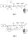
Fig. 3 is a schematic diagram of an embodiment of a fuel system of an aircraft in accordance with this disclosure; and -
Fig. 4 is a schematic diagram of an embodiment of a fuel system of an aircraft in accordance with this disclosure. - Reference will now be made to the drawings wherein like reference numerals identify similar structural features or aspects of the subject disclosure. For purposes of explanation and illustration, and not limitation, an illustrative view of an embodiment of a system in accordance with the disclosure is shown in
Fig. 1 and is designated generally byreference character 100. Other embodiments and/or aspects of this disclosure are shown inFigs. 2-4 . The systems and methods described herein can be used to prevent/reduce heat induced deposits forming on fuel system components which can prolong the life of the components. - Referring to
Fig. 1 , afuel stabilization system 100 for removing oxygen from fuel includes anaccumulator 101 disposed along afuel line 102. Theaccumulator 101 includes afuel inlet 103 and afuel outlet 105. Aheat source 107 is disposed in thermal communication with the fuel in or upstream of thefuel inlet 103 of theaccumulator 101 to increase the temperature of the fuel within theaccumulator 101. - The
accumulator 101 is configured to allow oxygen deposits (e.g., varnish/coke) to form therein as a result of the temperature increase of the fuel. For example, theaccumulator 101 can have a large surface area and be sufficiently dimensioned to promote deposits to form. In certain embodiments, theaccumulator 101 can be dimensioned based on a predetermined temperature (e.g., 149°C (300F), 427°C (800F)) of heated fuel entering theaccumulator 101 to allow for sufficient dwell time in theaccumulator 101 for the fuel to deoxygenate completely or near completely at the predetermined temperature. For example, in certain embodiments, temperature can be increased to reduce the size of the accumulator since less dwell time may be needed for a hotter fluid. Any suitable dimensions for theaccumulator 101 are contemplated herein. - The
accumulator 101 can include any suitable materials, coatings, or catalysts to promote the varnishing internally, for example, as is appreciated by those skilled in the art. For example, theaccumulator 101 can include foam, mesh, flat plates, serpentine flow path, or the like disposed on internal surfaces thereof. - The
accumulator 101 can be removable from thesystem 100 to allow replacement and/or refurbishment thereof (e.g., when coke/varnish buildup begins to degrade fuel flow performance). In certain embodiments, deposit buildup over time may be managed by in-situ burn-off, chemical treatment, replacement at regular intervals, and/or any suitable combination thereof. A filter may be utilized at an outlet of theaccumulator 101 to prevent any solids from leaving theaccumulator 101, for example. - The
heat source 107 can include a heater (e.g., a resistive heater as shown or any other suitable powered heater). In certain embodiments, theheat source 107 can include an engine system (e.g., a hot coolant/refrigerant circulated near the fuel line 102). Any othersuitable heat source 107 is contemplated herein. - In certain embodiments, the
system 100 can include at least onetemperature sensor 108 disposed in thermal communication with the fuel and/or theaccumulator 101 to sense a temperature of the fuel (e.g., flowing into the accumulator after heating from the heat source 107). In certain embodiments, thesystem 100 can include acontroller 110 that can control theheat source 107 based on temperature readings from thetemperature sensor 108, for example. - Referring to
Fig. 2 , thesystem 100 can further include aregenerative heat exchanger 109 disposed in thefuel line 102 such that it is both upstream and downstream of theaccumulator 101. The fuel upstream of theaccumulator 101 passes through aheating side 109a of theregenerative heat exchanger 109 to receive heat from fuel downstream of theaccumulator 101, which passes through acooling side 109b of theregenerative heat exchanger 109. - In certain embodiments, the
heat source 107 can be disposed downstream of theheating side 109a of theregenerative heat exchanger 109. Thecooling side 109b of theregenerative heat exchanger 109 can be downstream of and in fluid communication with thefuel outlet 105 of theaccumulator 101. In certain embodiments, any other suitable components can be disposed between theregenerative heat exchanger 109 and theaccumulator 101. - Referring to
Fig. 3 , in certain embodiments, embodiments of asystem 100 can be disposed immediately downstream of afuel tank 313 and upstream of all other fuel system components (e.g., a fuel nozzle 312). For example, one or more of afuel pump 315 and/or afuel valve 317 can be disposed downstream of thesystem 100. Any other suitable location is contemplated herein. For example, referring toFig. 4 , embodiments of asystem 100 can be disposed downstream of one ormore valves 317, pump 315, and downstream of heat addition from engine sources, but upstream of thefuel nozzle 312. Further, any suitable number of loops through theaccumulator 101, and/or any suitable number ofindependent accumulators 101 is contemplated herein. - However, in certain embodiments, an
accumulator 101 can be disposed at a branch in the fuel line leading to various actuators as appreciated by those having ordinary skill in the art. More specifically, for example, anaccumulator 101 can be disposed upstream of the actuator which drives the fuel metering valve. There, the flow rate is very low, which can allow for the accumulator to be of smaller size and lower weight. At the same time, many systems experience deposits in these portions of the fuel system. - In accordance with at least one aspect of this disclosure, a method for removing oxygen from fuel can include applying heat to fuel upstream of an
accumulator 101 to raise the temperature of the fuel to cause deposits to form on theaccumulator 101. Applying heat can include using a heater. Applying heat can include routing heat from an engine system. - The method can include reducing the temperature of the fuel downstream of the
accumulator 101. Applying heat to the fuel upstream of theaccumulator 101 can include extracting heat from the fuel downstream of the accumulator 101 (e.g., by passing the fuel through a regenerative heat exchanger 109). The method can include removing theaccumulator 101 to clean or replace theaccumulator 101 after deposit buildup. - In certain embodiments, the method can include monitoring a temperature of the fuel upstream of and/or within and/or downstream of the
accumulator 101. In such embodiments, applying heat can include applying heat as a function of the temperature of the fuel. The method can include monitoring a deposit buildup rate within theaccumulator 101 in any suitable manner (e.g. with electromagnetic sensors, via flow rate sensors). In such embodiments, applying heat may include applying heat as a function of the deposit buildup rate. - Embodiments as described above prevent/reduce temperature based fuel deposits (e.g., from oxygen) from building up on critical system components. Generally, the fuel temperature is raised in a strategic location to accumulate the byproducts of the reactions with dissolved oxygen at elevated temperature in a known location, serving as a varnish accumulator. The fuel would then re-enter the normal flow channel, with oxygen depleted and any varnish risk gone for the remainder of the system and the more critical components. This varnish accumulator could be periodically flushed or replaced to ensure long term operation.
- As described above, certain embodiments include an
accumulator 101 that has a large surface area and a sufficient dwell time for most or all of the oxygen in the fuel to be consumed making varnish. The temperature could be raised to any specified level and controlled via a temperature sensor to ensure that the fuel was sufficiently de-oxygenated before being returned to the line. - Embodiments as described above can employ a
regenerative heat exchanger 109 to minimize input heat needed from the heat source. Fuel enters the system, is heated on a heating side of aregenerative heat exchanger 109 to a temperature that promotes varnish formation and oxygen consumption, for example. Theregenerative heat exchanger 109 can be very efficient, minimizing heat input, and providing the maximum fuel temperature differential for thermal control downstream. The fuel can then be heated further to a desired temperature with the heat source (e.g., which could be powered heating, oil, higher temperature fuel, bleed air, or other suitable source). The fuel can then flow through theaccumulator 101 where varnish is intentionally plated out on the internal surfaces. Fuel can then exits the system being cooled by theregenerative heat exchanger 109 transferring its heat to the inlet stream. - Using a highly efficient regenerative heat exchanger, the fuel can be returned to the stream at nearly the same temperature it entered the
system 100, as shown inFig. 2 , for example, with a 95% efficiency. In such a case, the heater only supplies -12°C (10 degrees F) of a 93°C (200 degree F) rise, for example. - The methods and systems of the present disclosure, as described above and shown in the drawings, provide for fuel stabilization systems with superior properties. While the apparatus and methods of the subject disclosure have been shown and described with reference to embodiments, those skilled in the art will readily appreciate that changes and/or modifications may be made thereto without departing from the scope of the subject invention as defined by the claims.
Claims (15)
- A fuel stabilization system for removing dissolved oxygen from fuel, comprising:an accumulator (101) disposed along a fuel line (102), the accumulator includes a fuel inlet (103) and a fuel outlet (105); anda heat source (107) disposed in thermal communication with the fuel in or upstream of the fuel inlet of the accumulator to increase the temperature of the fuel within the accumulator, wherein the accumulator is configured to allow carbonaceous deposits to form therein as a result of the temperature increase of the fuel.
- The system of claim 1, wherein the heat source includes a heater, or wherein the heat source includes an engine system.
- The system of claim 1 or 2, further comprising a regenerative heat exchanger (109) disposed in the fuel line such that it is both upstream and downstream of the accumulator such that the fuel upstream of the accumulator passes through the regenerative heat exchanger to receive heat from fuel downstream of the accumulator,
- The system of claim 3, wherein the heat source (107) is disposed downstream of a heating side (109a) of the regenerative heat exchanger (109).
- The system of claim 4, wherein a cooling side (109b) of the regenerative heat exchanger is downstream of and in fluid communication with the fuel outlet of the accumulator.
- The system of any preceding claim, wherein the system is disposed immediately upstream of a branch leading to an actuator which drives a fuel metering valve.
- The system of any preceding claim, wherein one or more of a fuel pump (315) and/or a fuel valve (317) is disposed downstream of the system.
- The system of any preceding claim, wherein the accumulator is removable from the system to allow replacement and/or refurbishment thereof.
- A method for removing oxygen from fuel, comprising:applying heat to fuel upstream of an accumulator to raise the temperature of the fuel to cause deposits to form on the accumulator.
- The method of claim 9, wherein applying heat comprising using a heater, or wherein applying heat comprises routing heat from an engine system.
- The method of claim 9, further comprising reducing the temperature of the fuel downstream of the accumulator.
- The method of claim 11, wherein applying heat to the fuel upstream of the accumulator includes extracting heat from the fuel downstream of the accumulator.
- The method of claim 9, further comprising removing the accumulator to clean or replace the accumulator after deposit buildup.
- The method of claim 9, further comprising monitoring a temperature of the fuel upstream of and/or within and/or downstream of the accumulator, wherein applying heat includes applying heat as a function of the temperature of the fuel.
- The method of claim 14, further comprising monitoring a deposit buildup rate within the accumulator, wherein applying heat includes applying heat as a function of the deposit buildup rate.
Applications Claiming Priority (1)
| Application Number | Priority Date | Filing Date | Title |
|---|---|---|---|
| US15/334,005 US11052328B2 (en) | 2016-10-25 | 2016-10-25 | Fuel stabilization systems |
Publications (2)
| Publication Number | Publication Date |
|---|---|
| EP3315746A1 true EP3315746A1 (en) | 2018-05-02 |
| EP3315746B1 EP3315746B1 (en) | 2023-03-22 |
Family
ID=60186067
Family Applications (1)
| Application Number | Title | Priority Date | Filing Date |
|---|---|---|---|
| EP17198186.3A Active EP3315746B1 (en) | 2016-10-25 | 2017-10-25 | Fuel stabilization system and methodof removing oxygen from fuel |
Country Status (2)
| Country | Link |
|---|---|
| US (2) | US11052328B2 (en) |
| EP (1) | EP3315746B1 (en) |
Families Citing this family (2)
| Publication number | Priority date | Publication date | Assignee | Title |
|---|---|---|---|---|
| FR3106374B1 (en) * | 2020-01-21 | 2022-01-21 | Safran Aircraft Engines | FUEL SUPPLY CIRCUIT FOR A TURBOMACHINE COMBUSTION CHAMBER |
| US12012918B1 (en) | 2023-01-27 | 2024-06-18 | Hamilton Sundstrand Corporation | Systems and methods for coking mitigation in fuel supply systems |
Citations (5)
| Publication number | Priority date | Publication date | Assignee | Title |
|---|---|---|---|---|
| GB862214A (en) * | 1956-07-16 | 1961-03-08 | Koppers Gmbh Heinrich | Process for the catalytic pressure refining of crude benzene |
| US6709492B1 (en) * | 2003-04-04 | 2004-03-23 | United Technologies Corporation | Planar membrane deoxygenator |
| US20060263277A1 (en) * | 2005-05-18 | 2006-11-23 | United Technologies Corporation | Modular fuel stabilization system |
| EP1920810A2 (en) * | 2006-11-01 | 2008-05-14 | United Technologies Corporation | Acoustic degassing heat exchanger |
| US20110319698A1 (en) * | 2010-06-25 | 2011-12-29 | Uop Llc | Process for upgrading sweetened or oxygen-contaminated kerosene or jet fuel, to minimize or eliminate its tendency to polymerize or foul when heated |
Family Cites Families (7)
| Publication number | Priority date | Publication date | Assignee | Title |
|---|---|---|---|---|
| GB2111128B (en) * | 1981-12-10 | 1984-10-17 | Rolls Royce | Fuel/oil heat exchange system for a gas turbine engine |
| US6315815B1 (en) * | 1999-12-16 | 2001-11-13 | United Technologies Corporation | Membrane based fuel deoxygenator |
| US6415595B1 (en) * | 2000-08-22 | 2002-07-09 | Hamilton Sundstrand Corporation | Integrated thermal management and coolant system for an aircraft |
| US20060196811A1 (en) * | 2005-03-02 | 2006-09-07 | Eppig Christopher P | Influence of acoustic energy on coke morphology and foaming in delayed coking |
| US7513260B2 (en) * | 2006-05-10 | 2009-04-07 | United Technologies Corporation | In-situ continuous coke deposit removal by catalytic steam gasification |
| US9687773B2 (en) * | 2014-04-30 | 2017-06-27 | Honeywell International Inc. | Fuel deoxygenation and fuel tank inerting system and method |
| US9789972B2 (en) * | 2014-06-27 | 2017-10-17 | Hamilton Sundstrand Corporation | Fuel and thermal management system |
-
2016
- 2016-10-25 US US15/334,005 patent/US11052328B2/en active Active
-
2017
- 2017-10-25 EP EP17198186.3A patent/EP3315746B1/en active Active
-
2021
- 2021-06-03 US US17/338,432 patent/US20210292659A1/en not_active Abandoned
Patent Citations (5)
| Publication number | Priority date | Publication date | Assignee | Title |
|---|---|---|---|---|
| GB862214A (en) * | 1956-07-16 | 1961-03-08 | Koppers Gmbh Heinrich | Process for the catalytic pressure refining of crude benzene |
| US6709492B1 (en) * | 2003-04-04 | 2004-03-23 | United Technologies Corporation | Planar membrane deoxygenator |
| US20060263277A1 (en) * | 2005-05-18 | 2006-11-23 | United Technologies Corporation | Modular fuel stabilization system |
| EP1920810A2 (en) * | 2006-11-01 | 2008-05-14 | United Technologies Corporation | Acoustic degassing heat exchanger |
| US20110319698A1 (en) * | 2010-06-25 | 2011-12-29 | Uop Llc | Process for upgrading sweetened or oxygen-contaminated kerosene or jet fuel, to minimize or eliminate its tendency to polymerize or foul when heated |
Also Published As
| Publication number | Publication date |
|---|---|
| EP3315746B1 (en) | 2023-03-22 |
| US20210292659A1 (en) | 2021-09-23 |
| US11052328B2 (en) | 2021-07-06 |
| US20180111063A1 (en) | 2018-04-26 |
Similar Documents
| Publication | Publication Date | Title |
|---|---|---|
| EP2960158B1 (en) | Fuel and thermal management system | |
| US20210292659A1 (en) | Fuel stabilization systems | |
| US6939392B2 (en) | System and method for thermal management | |
| Amini et al. | Two objective optimization in shell-and-tube heat exchangers using genetic algorithm | |
| EP3269962B1 (en) | Filter screens and methods of making filter screens | |
| Sassi et al. | Optimal operation of RO system with daily variation of freshwater demand and seawater temperature | |
| US9021993B2 (en) | Water heater and flow rate control method | |
| JP2020534505A (en) | Cooling water monitoring and control system | |
| WO2017153429A1 (en) | Pipe assembly, cooling system with pipe assembly and method of cooling a fluid | |
| EP2592000B1 (en) | Fuel tank for aircraft provided with a fuel heating system, and fuel heating system for aircraft fitted with such a tank | |
| US20170336010A1 (en) | Method for managing the heating of fluids flowing through a network of submarine pipelines | |
| US5536390A (en) | Thermal decoking of cracking ovens and coolers | |
| WO2006046447A1 (en) | Head module, printing device, and printing method | |
| EP3428568B1 (en) | Heat exchanger | |
| JP2007030911A (en) | Apparatus for heat-treating container | |
| JP2018084355A (en) | Cleaning method for plate heat exchanger | |
| US20230204309A1 (en) | Method, system and apparatus for hydrocarbon flow system fluid cooling | |
| EP2630402B1 (en) | Means for supplying oil from a tank containing heavy fuel oil | |
| EP4162191B1 (en) | Apparatus and method for precipitation of solids in hydrocarbon flow systems | |
| JP5842597B2 (en) | Hot water storage water heater | |
| EP4407234B1 (en) | Systems and methods for coking mitigation in fuel supply systems | |
| WO2022031868A1 (en) | Heat exchange system for freezing transferring, storing, and utilizing phase change material and application of that system to a thermal energy storage system | |
| JPWO2017158938A1 (en) | Heat exchange system and method for suppressing scale of heat exchange system | |
| JP2013208575A (en) | Electrolytic apparatus and temperature adjusting water supply machine provided with the same | |
| Ramasamy et al. | EffectofBulkTemperatureand Heating Regimeon Crude Oil Fouling |
Legal Events
| Date | Code | Title | Description |
|---|---|---|---|
| PUAI | Public reference made under article 153(3) epc to a published international application that has entered the european phase |
Free format text: ORIGINAL CODE: 0009012 |
|
| STAA | Information on the status of an ep patent application or granted ep patent |
Free format text: STATUS: THE APPLICATION HAS BEEN PUBLISHED |
|
| AK | Designated contracting states |
Kind code of ref document: A1 Designated state(s): AL AT BE BG CH CY CZ DE DK EE ES FI FR GB GR HR HU IE IS IT LI LT LU LV MC MK MT NL NO PL PT RO RS SE SI SK SM TR |
|
| AX | Request for extension of the european patent |
Extension state: BA ME |
|
| STAA | Information on the status of an ep patent application or granted ep patent |
Free format text: STATUS: REQUEST FOR EXAMINATION WAS MADE |
|
| 17P | Request for examination filed |
Effective date: 20181102 |
|
| RBV | Designated contracting states (corrected) |
Designated state(s): AL AT BE BG CH CY CZ DE DK EE ES FI FR GB GR HR HU IE IS IT LI LT LU LV MC MK MT NL NO PL PT RO RS SE SI SK SM TR |
|
| STAA | Information on the status of an ep patent application or granted ep patent |
Free format text: STATUS: EXAMINATION IS IN PROGRESS |
|
| 17Q | First examination report despatched |
Effective date: 20200903 |
|
| RAP3 | Party data changed (applicant data changed or rights of an application transferred) |
Owner name: COLLINS ENGINE NOZZLES, INC. |
|
| GRAP | Despatch of communication of intention to grant a patent |
Free format text: ORIGINAL CODE: EPIDOSNIGR1 |
|
| STAA | Information on the status of an ep patent application or granted ep patent |
Free format text: STATUS: GRANT OF PATENT IS INTENDED |
|
| INTG | Intention to grant announced |
Effective date: 20221018 |
|
| GRAS | Grant fee paid |
Free format text: ORIGINAL CODE: EPIDOSNIGR3 |
|
| GRAA | (expected) grant |
Free format text: ORIGINAL CODE: 0009210 |
|
| STAA | Information on the status of an ep patent application or granted ep patent |
Free format text: STATUS: THE PATENT HAS BEEN GRANTED |
|
| AK | Designated contracting states |
Kind code of ref document: B1 Designated state(s): AL AT BE BG CH CY CZ DE DK EE ES FI FR GB GR HR HU IE IS IT LI LT LU LV MC MK MT NL NO PL PT RO RS SE SI SK SM TR |
|
| REG | Reference to a national code |
Ref country code: GB Ref legal event code: FG4D |
|
| REG | Reference to a national code |
Ref country code: CH Ref legal event code: EP |
|
| REG | Reference to a national code |
Ref country code: IE Ref legal event code: FG4D |
|
| REG | Reference to a national code |
Ref country code: DE Ref legal event code: R096 Ref document number: 602017066973 Country of ref document: DE |
|
| REG | Reference to a national code |
Ref country code: AT Ref legal event code: REF Ref document number: 1555421 Country of ref document: AT Kind code of ref document: T Effective date: 20230415 |
|
| REG | Reference to a national code |
Ref country code: LT Ref legal event code: MG9D |
|
| P01 | Opt-out of the competence of the unified patent court (upc) registered |
Effective date: 20230530 |
|
| REG | Reference to a national code |
Ref country code: NL Ref legal event code: MP Effective date: 20230322 |
|
| PG25 | Lapsed in a contracting state [announced via postgrant information from national office to epo] |
Ref country code: RS Free format text: LAPSE BECAUSE OF FAILURE TO SUBMIT A TRANSLATION OF THE DESCRIPTION OR TO PAY THE FEE WITHIN THE PRESCRIBED TIME-LIMIT Effective date: 20230322 Ref country code: NO Free format text: LAPSE BECAUSE OF FAILURE TO SUBMIT A TRANSLATION OF THE DESCRIPTION OR TO PAY THE FEE WITHIN THE PRESCRIBED TIME-LIMIT Effective date: 20230622 Ref country code: LV Free format text: LAPSE BECAUSE OF FAILURE TO SUBMIT A TRANSLATION OF THE DESCRIPTION OR TO PAY THE FEE WITHIN THE PRESCRIBED TIME-LIMIT Effective date: 20230322 Ref country code: LT Free format text: LAPSE BECAUSE OF FAILURE TO SUBMIT A TRANSLATION OF THE DESCRIPTION OR TO PAY THE FEE WITHIN THE PRESCRIBED TIME-LIMIT Effective date: 20230322 Ref country code: HR Free format text: LAPSE BECAUSE OF FAILURE TO SUBMIT A TRANSLATION OF THE DESCRIPTION OR TO PAY THE FEE WITHIN THE PRESCRIBED TIME-LIMIT Effective date: 20230322 |
|
| REG | Reference to a national code |
Ref country code: AT Ref legal event code: MK05 Ref document number: 1555421 Country of ref document: AT Kind code of ref document: T Effective date: 20230322 |
|
| PG25 | Lapsed in a contracting state [announced via postgrant information from national office to epo] |
Ref country code: SE Free format text: LAPSE BECAUSE OF FAILURE TO SUBMIT A TRANSLATION OF THE DESCRIPTION OR TO PAY THE FEE WITHIN THE PRESCRIBED TIME-LIMIT Effective date: 20230322 Ref country code: NL Free format text: LAPSE BECAUSE OF FAILURE TO SUBMIT A TRANSLATION OF THE DESCRIPTION OR TO PAY THE FEE WITHIN THE PRESCRIBED TIME-LIMIT Effective date: 20230322 Ref country code: GR Free format text: LAPSE BECAUSE OF FAILURE TO SUBMIT A TRANSLATION OF THE DESCRIPTION OR TO PAY THE FEE WITHIN THE PRESCRIBED TIME-LIMIT Effective date: 20230623 Ref country code: FI Free format text: LAPSE BECAUSE OF FAILURE TO SUBMIT A TRANSLATION OF THE DESCRIPTION OR TO PAY THE FEE WITHIN THE PRESCRIBED TIME-LIMIT Effective date: 20230322 |
|
| PG25 | Lapsed in a contracting state [announced via postgrant information from national office to epo] |
Ref country code: SM Free format text: LAPSE BECAUSE OF FAILURE TO SUBMIT A TRANSLATION OF THE DESCRIPTION OR TO PAY THE FEE WITHIN THE PRESCRIBED TIME-LIMIT Effective date: 20230322 Ref country code: RO Free format text: LAPSE BECAUSE OF FAILURE TO SUBMIT A TRANSLATION OF THE DESCRIPTION OR TO PAY THE FEE WITHIN THE PRESCRIBED TIME-LIMIT Effective date: 20230322 Ref country code: PT Free format text: LAPSE BECAUSE OF FAILURE TO SUBMIT A TRANSLATION OF THE DESCRIPTION OR TO PAY THE FEE WITHIN THE PRESCRIBED TIME-LIMIT Effective date: 20230724 Ref country code: ES Free format text: LAPSE BECAUSE OF FAILURE TO SUBMIT A TRANSLATION OF THE DESCRIPTION OR TO PAY THE FEE WITHIN THE PRESCRIBED TIME-LIMIT Effective date: 20230322 Ref country code: EE Free format text: LAPSE BECAUSE OF FAILURE TO SUBMIT A TRANSLATION OF THE DESCRIPTION OR TO PAY THE FEE WITHIN THE PRESCRIBED TIME-LIMIT Effective date: 20230322 Ref country code: AT Free format text: LAPSE BECAUSE OF FAILURE TO SUBMIT A TRANSLATION OF THE DESCRIPTION OR TO PAY THE FEE WITHIN THE PRESCRIBED TIME-LIMIT Effective date: 20230322 |
|
| PG25 | Lapsed in a contracting state [announced via postgrant information from national office to epo] |
Ref country code: SK Free format text: LAPSE BECAUSE OF FAILURE TO SUBMIT A TRANSLATION OF THE DESCRIPTION OR TO PAY THE FEE WITHIN THE PRESCRIBED TIME-LIMIT Effective date: 20230322 Ref country code: PL Free format text: LAPSE BECAUSE OF FAILURE TO SUBMIT A TRANSLATION OF THE DESCRIPTION OR TO PAY THE FEE WITHIN THE PRESCRIBED TIME-LIMIT Effective date: 20230322 Ref country code: IS Free format text: LAPSE BECAUSE OF FAILURE TO SUBMIT A TRANSLATION OF THE DESCRIPTION OR TO PAY THE FEE WITHIN THE PRESCRIBED TIME-LIMIT Effective date: 20230722 |
|
| REG | Reference to a national code |
Ref country code: DE Ref legal event code: R097 Ref document number: 602017066973 Country of ref document: DE |
|
| PLBE | No opposition filed within time limit |
Free format text: ORIGINAL CODE: 0009261 |
|
| STAA | Information on the status of an ep patent application or granted ep patent |
Free format text: STATUS: NO OPPOSITION FILED WITHIN TIME LIMIT |
|
| PG25 | Lapsed in a contracting state [announced via postgrant information from national office to epo] |
Ref country code: SI Free format text: LAPSE BECAUSE OF FAILURE TO SUBMIT A TRANSLATION OF THE DESCRIPTION OR TO PAY THE FEE WITHIN THE PRESCRIBED TIME-LIMIT Effective date: 20230322 Ref country code: DK Free format text: LAPSE BECAUSE OF FAILURE TO SUBMIT A TRANSLATION OF THE DESCRIPTION OR TO PAY THE FEE WITHIN THE PRESCRIBED TIME-LIMIT Effective date: 20230322 Ref country code: CZ Free format text: LAPSE BECAUSE OF FAILURE TO SUBMIT A TRANSLATION OF THE DESCRIPTION OR TO PAY THE FEE WITHIN THE PRESCRIBED TIME-LIMIT Effective date: 20230322 |
|
| 26N | No opposition filed |
Effective date: 20240102 |
|
| PG25 | Lapsed in a contracting state [announced via postgrant information from national office to epo] |
Ref country code: IT Free format text: LAPSE BECAUSE OF FAILURE TO SUBMIT A TRANSLATION OF THE DESCRIPTION OR TO PAY THE FEE WITHIN THE PRESCRIBED TIME-LIMIT Effective date: 20230322 Ref country code: MC Free format text: LAPSE BECAUSE OF FAILURE TO SUBMIT A TRANSLATION OF THE DESCRIPTION OR TO PAY THE FEE WITHIN THE PRESCRIBED TIME-LIMIT Effective date: 20230322 |
|
| REG | Reference to a national code |
Ref country code: CH Ref legal event code: PL |
|
| REG | Reference to a national code |
Ref country code: BE Ref legal event code: MM Effective date: 20231031 |
|
| PG25 | Lapsed in a contracting state [announced via postgrant information from national office to epo] |
Ref country code: LU Free format text: LAPSE BECAUSE OF NON-PAYMENT OF DUE FEES Effective date: 20231025 |
|
| PG25 | Lapsed in a contracting state [announced via postgrant information from national office to epo] |
Ref country code: LU Free format text: LAPSE BECAUSE OF NON-PAYMENT OF DUE FEES Effective date: 20231025 |
|
| PG25 | Lapsed in a contracting state [announced via postgrant information from national office to epo] |
Ref country code: CH Free format text: LAPSE BECAUSE OF NON-PAYMENT OF DUE FEES Effective date: 20231031 |
|
| PG25 | Lapsed in a contracting state [announced via postgrant information from national office to epo] |
Ref country code: CH Free format text: LAPSE BECAUSE OF NON-PAYMENT OF DUE FEES Effective date: 20231031 |
|
| PG25 | Lapsed in a contracting state [announced via postgrant information from national office to epo] |
Ref country code: BE Free format text: LAPSE BECAUSE OF NON-PAYMENT OF DUE FEES Effective date: 20231031 |
|
| PG25 | Lapsed in a contracting state [announced via postgrant information from national office to epo] |
Ref country code: IE Free format text: LAPSE BECAUSE OF NON-PAYMENT OF DUE FEES Effective date: 20231025 |
|
| PG25 | Lapsed in a contracting state [announced via postgrant information from national office to epo] |
Ref country code: IE Free format text: LAPSE BECAUSE OF NON-PAYMENT OF DUE FEES Effective date: 20231025 |
|
| PG25 | Lapsed in a contracting state [announced via postgrant information from national office to epo] |
Ref country code: BG Free format text: LAPSE BECAUSE OF FAILURE TO SUBMIT A TRANSLATION OF THE DESCRIPTION OR TO PAY THE FEE WITHIN THE PRESCRIBED TIME-LIMIT Effective date: 20230322 |
|
| PG25 | Lapsed in a contracting state [announced via postgrant information from national office to epo] |
Ref country code: BG Free format text: LAPSE BECAUSE OF FAILURE TO SUBMIT A TRANSLATION OF THE DESCRIPTION OR TO PAY THE FEE WITHIN THE PRESCRIBED TIME-LIMIT Effective date: 20230322 |
|
| PG25 | Lapsed in a contracting state [announced via postgrant information from national office to epo] |
Ref country code: CY Free format text: LAPSE BECAUSE OF FAILURE TO SUBMIT A TRANSLATION OF THE DESCRIPTION OR TO PAY THE FEE WITHIN THE PRESCRIBED TIME-LIMIT; INVALID AB INITIO Effective date: 20171025 |
|
| PG25 | Lapsed in a contracting state [announced via postgrant information from national office to epo] |
Ref country code: HU Free format text: LAPSE BECAUSE OF FAILURE TO SUBMIT A TRANSLATION OF THE DESCRIPTION OR TO PAY THE FEE WITHIN THE PRESCRIBED TIME-LIMIT; INVALID AB INITIO Effective date: 20171025 |
|
| PGFP | Annual fee paid to national office [announced via postgrant information from national office to epo] |
Ref country code: GB Payment date: 20250923 Year of fee payment: 9 |
|
| PGFP | Annual fee paid to national office [announced via postgrant information from national office to epo] |
Ref country code: FR Payment date: 20250924 Year of fee payment: 9 |
|
| PG25 | Lapsed in a contracting state [announced via postgrant information from national office to epo] |
Ref country code: TR Free format text: LAPSE BECAUSE OF FAILURE TO SUBMIT A TRANSLATION OF THE DESCRIPTION OR TO PAY THE FEE WITHIN THE PRESCRIBED TIME-LIMIT Effective date: 20230322 |
|
| PGFP | Annual fee paid to national office [announced via postgrant information from national office to epo] |
Ref country code: DE Payment date: 20250923 Year of fee payment: 9 |