EP3315648A1 - Washing and drying machine - Google Patents
Washing and drying machine Download PDFInfo
- Publication number
- EP3315648A1 EP3315648A1 EP17198193.9A EP17198193A EP3315648A1 EP 3315648 A1 EP3315648 A1 EP 3315648A1 EP 17198193 A EP17198193 A EP 17198193A EP 3315648 A1 EP3315648 A1 EP 3315648A1
- Authority
- EP
- European Patent Office
- Prior art keywords
- channel
- liquid
- washing
- processing chamber
- water
- Prior art date
- Legal status (The legal status is an assumption and is not a legal conclusion. Google has not performed a legal analysis and makes no representation as to the accuracy of the status listed.)
- Granted
Links
Images

Classifications
-
- D—TEXTILES; PAPER
- D06—TREATMENT OF TEXTILES OR THE LIKE; LAUNDERING; FLEXIBLE MATERIALS NOT OTHERWISE PROVIDED FOR
- D06F—LAUNDERING, DRYING, IRONING, PRESSING OR FOLDING TEXTILE ARTICLES
- D06F58/00—Domestic laundry dryers
- D06F58/20—General details of domestic laundry dryers
- D06F58/26—Heating arrangements, e.g. gas heating equipment
-
- D—TEXTILES; PAPER
- D06—TREATMENT OF TEXTILES OR THE LIKE; LAUNDERING; FLEXIBLE MATERIALS NOT OTHERWISE PROVIDED FOR
- D06F—LAUNDERING, DRYING, IRONING, PRESSING OR FOLDING TEXTILE ARTICLES
- D06F35/00—Washing machines, apparatus, or methods not otherwise provided for
-
- D—TEXTILES; PAPER
- D06—TREATMENT OF TEXTILES OR THE LIKE; LAUNDERING; FLEXIBLE MATERIALS NOT OTHERWISE PROVIDED FOR
- D06F—LAUNDERING, DRYING, IRONING, PRESSING OR FOLDING TEXTILE ARTICLES
- D06F2103/00—Parameters monitored or detected for the control of domestic laundry washing machines, washer-dryers or laundry dryers
- D06F2103/28—Air properties
- D06F2103/36—Flow or velocity
-
- D—TEXTILES; PAPER
- D06—TREATMENT OF TEXTILES OR THE LIKE; LAUNDERING; FLEXIBLE MATERIALS NOT OTHERWISE PROVIDED FOR
- D06F—LAUNDERING, DRYING, IRONING, PRESSING OR FOLDING TEXTILE ARTICLES
- D06F2105/00—Systems or parameters controlled or affected by the control systems of washing machines, washer-dryers or laundry dryers
- D06F2105/16—Air properties
- D06F2105/24—Flow or velocity
-
- D—TEXTILES; PAPER
- D06—TREATMENT OF TEXTILES OR THE LIKE; LAUNDERING; FLEXIBLE MATERIALS NOT OTHERWISE PROVIDED FOR
- D06F—LAUNDERING, DRYING, IRONING, PRESSING OR FOLDING TEXTILE ARTICLES
- D06F25/00—Washing machines with receptacles, e.g. perforated, having a rotary movement, e.g. oscillatory movement, the receptacle serving both for washing and for centrifugally separating water from the laundry and having further drying means, e.g. using hot air
-
- D—TEXTILES; PAPER
- D06—TREATMENT OF TEXTILES OR THE LIKE; LAUNDERING; FLEXIBLE MATERIALS NOT OTHERWISE PROVIDED FOR
- D06F—LAUNDERING, DRYING, IRONING, PRESSING OR FOLDING TEXTILE ARTICLES
- D06F35/00—Washing machines, apparatus, or methods not otherwise provided for
- D06F35/005—Methods for washing, rinsing or spin-drying
- D06F35/008—Methods for washing, rinsing or spin-drying for disinfecting the tub or the drum
-
- D—TEXTILES; PAPER
- D06—TREATMENT OF TEXTILES OR THE LIKE; LAUNDERING; FLEXIBLE MATERIALS NOT OTHERWISE PROVIDED FOR
- D06F—LAUNDERING, DRYING, IRONING, PRESSING OR FOLDING TEXTILE ARTICLES
- D06F58/00—Domestic laundry dryers
- D06F58/20—General details of domestic laundry dryers
- D06F58/203—Laundry conditioning arrangements
-
- D—TEXTILES; PAPER
- D06—TREATMENT OF TEXTILES OR THE LIKE; LAUNDERING; FLEXIBLE MATERIALS NOT OTHERWISE PROVIDED FOR
- D06F—LAUNDERING, DRYING, IRONING, PRESSING OR FOLDING TEXTILE ARTICLES
- D06F58/00—Domestic laundry dryers
- D06F58/30—Drying processes
Definitions
- the present invention relates to a washing and drying machine, and in particular, to an air heating apparatus of a washing and drying machine.
- a washing and drying machine usually includes a processing chamber, and an air heating channel in fluid communication with the processing chamber.
- a heating apparatus is disposed in the air heating channel for heating air supplied to the processing chamber in a drying program.
- the washing and drying machine has both the functions of washing and drying, the following problems exist: a large quantity of laundry fluffs generated in the drying process easily accumulate in a condensation channel, and residual dirt, in particular, oily dirt such as sebum in the washing process is also attached on the fluffs, and is difficult to rinse; long-term laundry detergent residues in a detergent dispenser cause mildewing; washing water, foams, and the like remain on the bottom of a door gasket after washing, and consequently cause mildewing and bacteria breeding; and a large amount of dirt, and the like accumulate on an inner wall of the processing chamber after long-term washing. In addition, additional steam or hot water usually needs to be provided in the washing and drying process.
- An objective of the present invention is to resolve the foregoing problems in the related art.
- the present invention provides a washing and drying machine as defined in the independent claim attached.
- Preferred facultative embodiments of the invention are defined in respective dependent claims, where different embodiments as defined may also be combined among themselves for yielding further preferred embodiments, described in the subsequent description, or exhibited in the drawing attached.
- the present invention accordingly provides a washing and drying machine, including a processing chamber and an air heating channel in fluid communication with the processing chamber.
- a heating apparatus is disposed in the air heating channel;
- a liquid flow-through apparatus is disposed close to or surrounding the heating apparatus;
- an input channel and an output channel are connected to the liquid flow-through apparatus; and
- the output channel is connected to at least one of a detergent dispenser, a door gasket, the processing chamber, or a condensation channel.
- a fluid is heated by the heating apparatus after entering the liquid flow-through apparatus from the input channel, and then flows out of the output channel, so that a heated liquid is obtained.
- high-temperature steam after the liquid is evaporated may be obtained.
- the heated liquid or high-temperature steam is conveyed to at least one of the detergent dispenser, the door gasket, the processing chamber, or the condensation channel through the output channel, so as to perform cleaning, sterilization, and mildew prevention on the parts.
- the heated liquid or high-temperature steam can perform functions such as sterilization, wrinkle elimination, washing effect enhancement on laundry. In addition, transformation on the existing drying machine is small.
- the input channel is connected to a circulation pump, so as to be connected to the processing chamber through the circulation pump.
- a washing liquid is pumped into the liquid flow-through apparatus by using the circulation pump, and enters at least one of the detergent dispenser, the door gasket, the processing chamber, or the condensation channel in a liquid or steam form after being heated in the liquid flow-through apparatus.
- the final liquid or steam returns back to the processing chamber.
- a nozzle that converts a liquid into water mist is disposed on a tail end of the output channel.
- High-temperature water can generate high-temperature water mist after passing through the nozzle.
- a control apparatus is included, where the control apparatus controls the heating apparatus, so as to adjust the temperature of a liquid or a water-vapor mixture output from the output channel.
- a fan that promotes air to flow to the processing chamber from the air heating channel is included, where the fan is controlled by the control apparatus so as to be able to change the rotation speed, and hence adjust the temperature of a liquid or a water-vapor mixture output from the output channel.
- the rotation speed of the fan is high, the air flow that passes through the air heating channel is large, and the amount of heat that is generated by the heating apparatus and distributed to air is relatively large, and the amount of heat distributed to the liquid flow-through apparatus is relatively small. Then, the temperature of the liquid or water-vapor mixture output by the output channel is relatively low, and otherwise, the temperature of the liquid or water-vapor mixture output by the output channel is relatively high.
- the input channel is connected to a water valve or a circulation pump, and the control apparatus can control an on/off rhythm of the water valve or the circulation pump, so as to adjust the temperature of a liquid or a water-vapor mixture output from the output channel.
- the amount of the liquid that enters the liquid flow-through apparatus is adjusted by controlling an on/off rhythm of the control valve or circulation pump.
- the amount of the liquid that enters the liquid flow-through apparatus within unit time is relatively small, the temperature of the liquid or water-vapor mixture output by the output channel is relatively high, and otherwise, the temperature of the liquid or water-vapor mixture output by the output channel is relatively low.
- a washing and drying machine includes a processing chamber 2 for accommodating laundry, and an air heating channel 3 in fluid communication with the processing chamber.
- a fan 4 is disposed upstream of the air heating channel 3, to promote air to enter the processing chamber 2 from the air heating channel 3.
- a heating apparatus 5 is disposed in the air heating channel 3, to heat air that flows through the air heating channel 3.
- a liquid flow-through apparatus 6 is disposed close to the heating apparatus 5.
- the liquid flow-through apparatus 6 is connected to an input channel 7 and an output channel 8.
- a liquid, mainly water or washing water formed by mixing water and detergent enters the liquid flow-through apparatus 6 from the input channel 7, and then is heated because the liquid is close to the heating apparatus 5. Then the liquid is output from the output channel 8 into the processing chamber 2.
- the liquid flow-through apparatus 6 is constructed into a shape suitable for flowing of the liquid therein.
- the liquid flow-through apparatus 6 is a plate-shaped structure 61 with an open top, and the heating apparatus 5 is located in the plate-shaped structure 61.
- the heating apparatus 5 may alternatively be located above or below the plate-shaped structure 61.
- the liquid flow-through apparatus 6 is a water tank 62 with a closed top, and the heating apparatus 5 is located in the water tank 62 or located above or below the water tank 62.
- the difference between the plate-shaped structure 61 and the water tank 62 may lie only in whether the top is open or closed, and it can be seen from top-view projection images that the plate-shaped structure 61 is relatively similar to the water tank 62. Therefore, the liquid flow-through apparatus 6 in the form of the plate-shaped structure 61 and the water tank 62 is represented by using a same mechanism in FIG. 1 .
- a person skilled in the art can clearly determine content of the foregoing implementation with reference to the specification and the accompanying drawings.
- a liquid flow-through apparatus 63 is an extending curved-shaped pipe 63 that has a shape similar to that of a heating apparatus 5.
- the liquid flow-through apparatus 63 is adjacent to the heating apparatus 5 and is closer to a heat source, and therefore can absorb more heat, so that a liquid therein can be quickly heated.
- an outlet of an output channel 8 is located in an air heating channel 3. Then, a liquid flowing out of the output channel 8 directly falls onto the bottom of the air heating channel 3. A hydrophilic coating 20 is covered on an inner surface of the bottom of the air heating channel 3. Then, the high-temperature liquid expands on the inner surface of the bottom of the air heating channel 3 to form a water film. When being further heated by a heating apparatus 5, the water film can be vaporized to generate steam into a processing chamber 2. When a fan 4 is started, hot air quickly evaporates the liquid on a surface of the water film to form a large amount of steam.
- a nozzle 21 that converts a liquid into water mist may be disposed on a tail end of the output channel 8.
- the nozzle 21 may be disposed on the output channel 8 in the foregoing various implementations.
- an input channel 7 may be enabled to input a relatively small amount of liquid within unit time, and the heating apparatus 5 may be enabled to generate a relatively high temperature, so that the liquid is evaporated under the effect of high temperature to generate steam.
- a water valve 9 controlled by a control apparatus 10 is disposed on the input channel 7, as shown in FIG. 5 , or a circulation pump 11 is disposed as shown in FIG. 4 .
- An input end of the circulation pump 11 is connected to the processing chamber 2, so as to pump the liquid in the processing chamber 2 into the liquid flow-through apparatus 6.
- the processing chamber 2 mentioned above not only can be used as a drying chamber, but also can be used as a washing chamber.
- a high-temperature liquid or a high-temperature liquid-vapor mixture output in the output channel 8 can be conveyed to a suitable part according to a design requirement.
- an output channel 8 is connected to a door gasket 12.
- An outlet 81 of the output channel 8 is close to the bottom of the door gasket 12, and a washing liquid and foam easily accumulate on this part, and consequently a bacterial film is formed.
- a high-temperature liquid or high-temperature liquid-vapor mixture output by the output channel 8 can rinse the part, to prevent generation of a bacterial film and keep clean. Subsequently, the high-temperature liquid flows into the processing chamber 2 to participate in washing laundry.
- the output channel 8 may be directly connected to the processing chamber 2, in particular, on a rear part, on which dirt easily accumulates, of the processing chamber 2, so that not only the part can be kept clean, but also the high-temperature liquid can subsequently participate in washing laundry.
- the output channel 8 may further be connected to a detergent dispenser 13 and/or a condensation channel 14, so as to perform cleaning, sterilization, mildew prevention, and the like.
- the output channel 8 may be connected to a single component in the foregoing implementations, or may include multiple pipes to be connected to multiple components.
- a control apparatus 10 is connected to a fan 4, a heating apparatus 5, and a water valve 9 or a circulation pump 11.
- the temperature of a liquid or a water-vapor mixture output by an output channel 8 can be adjusted by adjusting the power or on/off rhythm of the heating apparatus 5, the rotation speed of the fan 4, and/or the on/off rhythm of the water valve 9 or circulation pump 11 by using the control apparatus 10.
- a ratio of heat of the heating apparatus 5 transferred to the liquid to air can be adjusted.
- the air flow can be reduced, so that heat transferred to air is reduced.
- the temperature of the liquid or water-vapor mixture discharged by the output channel 8 can be increased.
- the fan 4 is switched off, air in the air heating channel 3 performs natural convection. After air reaches a particular temperature, most heat of the heating apparatus 5 is used to heat the liquid in the liquid flow-through apparatus 6.
- the control apparatus 10 further controls a washing program.
- the washing program includes a main washing phase, a rinsing phase, and a spin-drying phase.
- the heating apparatus 5 and the water valve 9 are first started. Water is heated by the heating apparatus 5 after entering the liquid flow-through apparatus 6 from an input channel 7, and then is output into a processing chamber 2 from the output channel 8. High-temperature water or a liquid-vapor mixture may be output into the processing chamber 2.
- the control apparatus 10 simultaneously starts the fan 4, so that the air heating channel 3 outputs heated air to the processing chamber 2 when the output channel 8 outputs the heated water or liquid-vapor mixture to the processing chamber 2.
- High-temperature air, water, liquid-vapor mixture, and the like entering the processing chamber 2 come into contact with laundry to heat and sterilize the laundry. Because the laundry are in a relatively dry state at the moment, the laundry can quickly reach a relatively high temperature, so as to kill bacteria in the laundry. Moreover, damages such as fading and shrinkage of laundry are reduced when heating is performed in a dry state. Laundry that enter the subsequent main washing phase after the sterilization is completed are more hygienic. Moreover, the laundry are already in a high-temperature state at the moment, and the activity of detergent in the subsequent main washing phase is improved. In addition, the high-temperature water or liquid-vapor mixture entering the processing chamber 2 from the output channel 8 is also used in the subsequent main washing phase.
- the heating apparatus 5 and the water valve 9 may also be in a started state in the main washing phase and/or the rinsing phase.
- the heating apparatus 5 and the water pump 9 may also be started in an initial part of the main washing phase.
- the heating apparatus 5 and the circulation pump 11 are started in the main washing phase and/or rinsing phase. Then the washing liquid in the processing chamber 2 is circularly heated, and can clean and sterilize a detergent dispenser 13, a door gasket 12, and a condensation channel 14 before entering the processing chamber 2.
Landscapes
- Engineering & Computer Science (AREA)
- Textile Engineering (AREA)
- Detail Structures Of Washing Machines And Dryers (AREA)
- Control Of Washing Machine And Dryer (AREA)
- Drying Of Solid Materials (AREA)
Abstract
Description
- The present invention relates to a washing and drying machine, and in particular, to an air heating apparatus of a washing and drying machine.
- A washing and drying machine usually includes a processing chamber, and an air heating channel in fluid communication with the processing chamber. A heating apparatus is disposed in the air heating channel for heating air supplied to the processing chamber in a drying program.
- Because the washing and drying machine has both the functions of washing and drying, the following problems exist: a large quantity of laundry fluffs generated in the drying process easily accumulate in a condensation channel, and residual dirt, in particular, oily dirt such as sebum in the washing process is also attached on the fluffs, and is difficult to rinse; long-term laundry detergent residues in a detergent dispenser cause mildewing; washing water, foams, and the like remain on the bottom of a door gasket after washing, and consequently cause mildewing and bacteria breeding; and a large amount of dirt, and the like accumulate on an inner wall of the processing chamber after long-term washing. In addition, additional steam or hot water usually needs to be provided in the washing and drying process.
- An objective of the present invention is to resolve the foregoing problems in the related art.
- To achieve the foregoing objective, the present invention provides a washing and drying machine as defined in the independent claim attached. Preferred facultative embodiments of the invention are defined in respective dependent claims, where different embodiments as defined may also be combined among themselves for yielding further preferred embodiments, described in the subsequent description, or exhibited in the drawing attached.
- To achieve the foregoing objective, the present invention accordingly provides a washing and drying machine, including a processing chamber and an air heating channel in fluid communication with the processing chamber. A heating apparatus is disposed in the air heating channel; a liquid flow-through apparatus is disposed close to or surrounding the heating apparatus; an input channel and an output channel are connected to the liquid flow-through apparatus; and the output channel is connected to at least one of a detergent dispenser, a door gasket, the processing chamber, or a condensation channel.
- A fluid is heated by the heating apparatus after entering the liquid flow-through apparatus from the input channel, and then flows out of the output channel, so that a heated liquid is obtained. When the liquid flow is relatively small, high-temperature steam after the liquid is evaporated may be obtained. The heated liquid or high-temperature steam is conveyed to at least one of the detergent dispenser, the door gasket, the processing chamber, or the condensation channel through the output channel, so as to perform cleaning, sterilization, and mildew prevention on the parts. When being used in a washing program or a drying program, the heated liquid or high-temperature steam can perform functions such as sterilization, wrinkle elimination, washing effect enhancement on laundry. In addition, transformation on the existing drying machine is small.
- Preferably, the input channel is connected to a circulation pump, so as to be connected to the processing chamber through the circulation pump. Then, a washing liquid is pumped into the liquid flow-through apparatus by using the circulation pump, and enters at least one of the detergent dispenser, the door gasket, the processing chamber, or the condensation channel in a liquid or steam form after being heated in the liquid flow-through apparatus. Regardless of a component connected to the output channel, the final liquid or steam returns back to the processing chamber. By means of work of the circulation pump, the liquid in the processing chamber can be continuously heated, and sterilization, cleaning, and the like may also be simultaneously performed on other components, and the generated steam can further perform sterilization and wrinkle elimination on laundry after entering the processing chamber.
- Preferably, a nozzle that converts a liquid into water mist is disposed on a tail end of the output channel. High-temperature water can generate high-temperature water mist after passing through the nozzle.
- Preferably, a control apparatus is included, where the control apparatus controls the heating apparatus, so as to adjust the temperature of a liquid or a water-vapor mixture output from the output channel.
- Preferably, a fan that promotes air to flow to the processing chamber from the air heating channel is included, where the fan is controlled by the control apparatus so as to be able to change the rotation speed, and hence adjust the temperature of a liquid or a water-vapor mixture output from the output channel. When the rotation speed of the fan is high, the air flow that passes through the air heating channel is large, and the amount of heat that is generated by the heating apparatus and distributed to air is relatively large, and the amount of heat distributed to the liquid flow-through apparatus is relatively small. Then, the temperature of the liquid or water-vapor mixture output by the output channel is relatively low, and otherwise, the temperature of the liquid or water-vapor mixture output by the output channel is relatively high.
- Preferably, the input channel is connected to a water valve or a circulation pump, and the control apparatus can control an on/off rhythm of the water valve or the circulation pump, so as to adjust the temperature of a liquid or a water-vapor mixture output from the output channel. The amount of the liquid that enters the liquid flow-through apparatus is adjusted by controlling an on/off rhythm of the control valve or circulation pump. When the amount of the liquid that enters the liquid flow-through apparatus within unit time is relatively small, the temperature of the liquid or water-vapor mixture output by the output channel is relatively high, and otherwise, the temperature of the liquid or water-vapor mixture output by the output channel is relatively low.
- Preferred embodiments of the present invention will be further described below with reference to the accompanying drawing. The disclosure will become more fully understood from the detailed description given hereinbelow for illustration only, and thus not limitative of the disclosure. In the drawing:
-
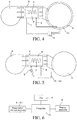
FIG. 1 is a partial schematic diagram of a washing and drying machine according to a first implementation; -
FIG. 2 is a partial schematic diagram of a washing and drying machine according to a second implementation; -
FIG. 3 is a partial schematic diagram of a washing and drying machine according to a third implementation; -
FIG. 4 is a partial schematic diagram of a washing and drying machine according to a fourth implementation; -
FIG. 5 is a partial schematic diagram of a washing and drying machine according to a fifth implementation; and -
FIG. 6 is a schematic diagram of connection of a control system of a washing and drying machine. - As shown in
FIG. 1 , a washing and drying machine includes aprocessing chamber 2 for accommodating laundry, and anair heating channel 3 in fluid communication with the processing chamber. Afan 4 is disposed upstream of theair heating channel 3, to promote air to enter theprocessing chamber 2 from theair heating channel 3. Aheating apparatus 5 is disposed in theair heating channel 3, to heat air that flows through theair heating channel 3. A liquid flow-throughapparatus 6 is disposed close to theheating apparatus 5. The liquid flow-throughapparatus 6 is connected to aninput channel 7 and anoutput channel 8. A liquid, mainly water or washing water formed by mixing water and detergent, enters the liquid flow-throughapparatus 6 from theinput channel 7, and then is heated because the liquid is close to theheating apparatus 5. Then the liquid is output from theoutput channel 8 into theprocessing chamber 2. - The liquid flow-through
apparatus 6 is constructed into a shape suitable for flowing of the liquid therein. - For example, in the implementation shown in
FIG. 1 , the liquid flow-throughapparatus 6 is a plate-shaped structure 61 with an open top, and theheating apparatus 5 is located in the plate-shaped structure 61. In other alternative implementations, theheating apparatus 5 may alternatively be located above or below the plate-shaped structure 61. In other alternative implementations, the liquid flow-throughapparatus 6 is awater tank 62 with a closed top, and theheating apparatus 5 is located in thewater tank 62 or located above or below thewater tank 62. - The difference between the plate-
shaped structure 61 and thewater tank 62 may lie only in whether the top is open or closed, and it can be seen from top-view projection images that the plate-shaped structure 61 is relatively similar to thewater tank 62. Therefore, the liquid flow-throughapparatus 6 in the form of the plate-shaped structure 61 and thewater tank 62 is represented by using a same mechanism inFIG. 1 . A person skilled in the art can clearly determine content of the foregoing implementation with reference to the specification and the accompanying drawings. - In the implementation shown in
FIG. 2 , a liquid flow-throughapparatus 63 is an extending curved-shaped pipe 63 that has a shape similar to that of aheating apparatus 5. The liquid flow-throughapparatus 63 is adjacent to theheating apparatus 5 and is closer to a heat source, and therefore can absorb more heat, so that a liquid therein can be quickly heated. - In the implementation shown in
FIG. 3 , an outlet of anoutput channel 8 is located in anair heating channel 3. Then, a liquid flowing out of theoutput channel 8 directly falls onto the bottom of theair heating channel 3. Ahydrophilic coating 20 is covered on an inner surface of the bottom of theair heating channel 3. Then, the high-temperature liquid expands on the inner surface of the bottom of theair heating channel 3 to form a water film. When being further heated by aheating apparatus 5, the water film can be vaporized to generate steam into aprocessing chamber 2. When afan 4 is started, hot air quickly evaporates the liquid on a surface of the water film to form a large amount of steam. - If high-temperature water mist is generated for objectives such as cleaning and sterilization, in some implementations, a
nozzle 21 that converts a liquid into water mist may be disposed on a tail end of theoutput channel 8. Thenozzle 21 may be disposed on theoutput channel 8 in the foregoing various implementations. - Alternatively, an
input channel 7 may be enabled to input a relatively small amount of liquid within unit time, and theheating apparatus 5 may be enabled to generate a relatively high temperature, so that the liquid is evaporated under the effect of high temperature to generate steam. Awater valve 9 controlled by acontrol apparatus 10 is disposed on theinput channel 7, as shown inFIG. 5 , or acirculation pump 11 is disposed as shown inFIG. 4 . An input end of thecirculation pump 11 is connected to theprocessing chamber 2, so as to pump the liquid in theprocessing chamber 2 into the liquid flow-throughapparatus 6. - The
processing chamber 2 mentioned above not only can be used as a drying chamber, but also can be used as a washing chamber. - A high-temperature liquid or a high-temperature liquid-vapor mixture output in the
output channel 8 can be conveyed to a suitable part according to a design requirement. - As shown in
FIG. 4 , anoutput channel 8 is connected to adoor gasket 12. An outlet 81 of theoutput channel 8 is close to the bottom of thedoor gasket 12, and a washing liquid and foam easily accumulate on this part, and consequently a bacterial film is formed. A high-temperature liquid or high-temperature liquid-vapor mixture output by theoutput channel 8 can rinse the part, to prevent generation of a bacterial film and keep clean. Subsequently, the high-temperature liquid flows into theprocessing chamber 2 to participate in washing laundry. - Alternatively, the
output channel 8 may be directly connected to theprocessing chamber 2, in particular, on a rear part, on which dirt easily accumulates, of theprocessing chamber 2, so that not only the part can be kept clean, but also the high-temperature liquid can subsequently participate in washing laundry. - In addition, as shown in
FIG. 5 , in other implementations, theoutput channel 8 may further be connected to adetergent dispenser 13 and/or acondensation channel 14, so as to perform cleaning, sterilization, mildew prevention, and the like. - The
output channel 8 may be connected to a single component in the foregoing implementations, or may include multiple pipes to be connected to multiple components. - As shown in
FIG. 6 , acontrol apparatus 10 is connected to afan 4, aheating apparatus 5, and awater valve 9 or acirculation pump 11. The temperature of a liquid or a water-vapor mixture output by anoutput channel 8 can be adjusted by adjusting the power or on/off rhythm of theheating apparatus 5, the rotation speed of thefan 4, and/or the on/off rhythm of thewater valve 9 orcirculation pump 11 by using thecontrol apparatus 10. By adjusting the rotation speed of thefan 4, a ratio of heat of theheating apparatus 5 transferred to the liquid to air can be adjusted. By reducing the rotation speed of thefan 4, the air flow can be reduced, so that heat transferred to air is reduced. Then, the temperature of the liquid or water-vapor mixture discharged by theoutput channel 8 can be increased. In particular, when thefan 4 is switched off, air in theair heating channel 3 performs natural convection. After air reaches a particular temperature, most heat of theheating apparatus 5 is used to heat the liquid in the liquid flow-throughapparatus 6. - The
control apparatus 10 further controls a washing program. The washing program includes a main washing phase, a rinsing phase, and a spin-drying phase. Before the main washing phase of the washing program, theheating apparatus 5 and thewater valve 9 are first started. Water is heated by theheating apparatus 5 after entering the liquid flow-throughapparatus 6 from aninput channel 7, and then is output into aprocessing chamber 2 from theoutput channel 8. High-temperature water or a liquid-vapor mixture may be output into theprocessing chamber 2. Preferably, thecontrol apparatus 10 simultaneously starts thefan 4, so that theair heating channel 3 outputs heated air to theprocessing chamber 2 when theoutput channel 8 outputs the heated water or liquid-vapor mixture to theprocessing chamber 2. High-temperature air, water, liquid-vapor mixture, and the like entering theprocessing chamber 2 come into contact with laundry to heat and sterilize the laundry. Because the laundry are in a relatively dry state at the moment, the laundry can quickly reach a relatively high temperature, so as to kill bacteria in the laundry. Moreover, damages such as fading and shrinkage of laundry are reduced when heating is performed in a dry state. Laundry that enter the subsequent main washing phase after the sterilization is completed are more hygienic. Moreover, the laundry are already in a high-temperature state at the moment, and the activity of detergent in the subsequent main washing phase is improved. In addition, the high-temperature water or liquid-vapor mixture entering theprocessing chamber 2 from theoutput channel 8 is also used in the subsequent main washing phase. - In addition, the
heating apparatus 5 and thewater valve 9 may also be in a started state in the main washing phase and/or the rinsing phase. For example, theheating apparatus 5 and thewater pump 9 may also be started in an initial part of the main washing phase. When theinput channel 7 is connected to thecirculation pump 11, theheating apparatus 5 and thecirculation pump 11 are started in the main washing phase and/or rinsing phase. Then the washing liquid in theprocessing chamber 2 is circularly heated, and can clean and sterilize adetergent dispenser 13, adoor gasket 12, and acondensation channel 14 before entering theprocessing chamber 2.
Claims (6)
- A washing and drying machine, comprising a processing chamber (2) and an air heating channel (3) in fluid communication with the processing chamber; a heating apparatus (5) being disposed in the air heating channel, characterized in that: a liquid flow-through apparatus (6, 61, 62, 63) is disposed close to or surrounding the heating apparatus; an input channel (7) and an output channel (8) are connected to the liquid flow-through apparatus; and the output channel (8) is connected to at least one of a detergent dispenser (13), a door gasket (12), the processing chamber (2), or a condensation channel (14).
- The washing and drying machine according to claim 1, characterized in that: the input channel (7) is connected to a circulation pump (11), so as to be connected to the processing chamber through the circulation pump.
- The washing and drying machine according to claim 1, characterized in that: a nozzle (21) that converts a liquid into water mist is disposed on a tail end of the output channel (8).
- The washing and drying machine according to claim 1, characterized by comprising a control apparatus (10), wherein the control apparatus controls the heating apparatus, so as to adjust the temperature of a liquid or a water-vapor mixture output from the output channel.
- The washing and drying machine according to claim 1, characterized by comprising a fan (4) that promotes air to flow to the processing chamber from the air heating channel, wherein the fan is controlled by the control apparatus (10) so as to be able to change the rotation speed, and hence adjust the temperature of a liquid or a water-vapor mixture output from the output channel.
- The washing and drying machine according to claim 1, characterized in that: the input channel (7) is connected to a water valve (9) or a circulation pump (11), and the control apparatus can control an on/off rhythm of the water valve or the circulation pump, so as to adjust the temperature of a liquid or a water-vapor mixture output from the output channel.
Priority Applications (1)
| Application Number | Priority Date | Filing Date | Title |
|---|---|---|---|
| PL17198193T PL3315648T3 (en) | 2016-10-31 | 2017-10-25 | Washing and drying machine |
Applications Claiming Priority (1)
| Application Number | Priority Date | Filing Date | Title |
|---|---|---|---|
| CN201610929745.5A CN108018669B (en) | 2016-10-31 | 2016-10-31 | Washing and drying machine |
Publications (2)
| Publication Number | Publication Date |
|---|---|
| EP3315648A1 true EP3315648A1 (en) | 2018-05-02 |
| EP3315648B1 EP3315648B1 (en) | 2020-06-17 |
Family
ID=60182437
Family Applications (1)
| Application Number | Title | Priority Date | Filing Date |
|---|---|---|---|
| EP17198193.9A Active EP3315648B1 (en) | 2016-10-31 | 2017-10-25 | Washing and drying machine |
Country Status (3)
| Country | Link |
|---|---|
| EP (1) | EP3315648B1 (en) |
| CN (1) | CN108018669B (en) |
| PL (1) | PL3315648T3 (en) |
Cited By (1)
| Publication number | Priority date | Publication date | Assignee | Title |
|---|---|---|---|---|
| DE102018213432B3 (en) | 2018-08-09 | 2020-01-23 | E.G.O. Elektro-Gerätebau GmbH | Tumble dryer and method for operating a tumble dryer |
Citations (5)
| Publication number | Priority date | Publication date | Assignee | Title |
|---|---|---|---|---|
| EP1992730A1 (en) * | 2007-05-16 | 2008-11-19 | Samsung Electronics Co., Ltd. | Washing machine with steam generator |
| US20090249639A1 (en) * | 2008-04-02 | 2009-10-08 | Samsung Electronics Co., Ltd. | Dryer and method of controlling cleaning operation thereof |
| EP2287389A1 (en) * | 2009-08-18 | 2011-02-23 | BSH Bosch und Siemens Hausgeräte GmbH | Steam injection arrangement for a laundry appliance, and laundry appliance |
| US20120005915A1 (en) * | 2009-04-02 | 2012-01-12 | Lg Electronics Inc. | Clothes dryer having a steam generator using a hot air heater |
| EP3051016A1 (en) * | 2015-02-02 | 2016-08-03 | LG Electronics Inc. | Method of controlling drum type washing machine |
Family Cites Families (5)
| Publication number | Priority date | Publication date | Assignee | Title |
|---|---|---|---|---|
| KR100753507B1 (en) * | 2005-03-25 | 2007-08-31 | 엘지전자 주식회사 | Drum washing machine |
| KR100662473B1 (en) * | 2006-02-20 | 2007-01-02 | 엘지전자 주식회사 | Dryer using steam generator |
| KR101467773B1 (en) * | 2008-04-01 | 2014-12-03 | 엘지전자 주식회사 | Laundry treating machine and control method of the same |
| EP2623662B1 (en) * | 2012-02-06 | 2018-04-04 | LG Electronics Inc. | Laundry machine and control method thereof |
| CN105463812B (en) * | 2015-12-30 | 2019-03-01 | Tcl家用电器(合肥)有限公司 | Washing and drying machine |
-
2016
- 2016-10-31 CN CN201610929745.5A patent/CN108018669B/en not_active Expired - Fee Related
-
2017
- 2017-10-25 EP EP17198193.9A patent/EP3315648B1/en active Active
- 2017-10-25 PL PL17198193T patent/PL3315648T3/en unknown
Patent Citations (5)
| Publication number | Priority date | Publication date | Assignee | Title |
|---|---|---|---|---|
| EP1992730A1 (en) * | 2007-05-16 | 2008-11-19 | Samsung Electronics Co., Ltd. | Washing machine with steam generator |
| US20090249639A1 (en) * | 2008-04-02 | 2009-10-08 | Samsung Electronics Co., Ltd. | Dryer and method of controlling cleaning operation thereof |
| US20120005915A1 (en) * | 2009-04-02 | 2012-01-12 | Lg Electronics Inc. | Clothes dryer having a steam generator using a hot air heater |
| EP2287389A1 (en) * | 2009-08-18 | 2011-02-23 | BSH Bosch und Siemens Hausgeräte GmbH | Steam injection arrangement for a laundry appliance, and laundry appliance |
| EP3051016A1 (en) * | 2015-02-02 | 2016-08-03 | LG Electronics Inc. | Method of controlling drum type washing machine |
Cited By (1)
| Publication number | Priority date | Publication date | Assignee | Title |
|---|---|---|---|---|
| DE102018213432B3 (en) | 2018-08-09 | 2020-01-23 | E.G.O. Elektro-Gerätebau GmbH | Tumble dryer and method for operating a tumble dryer |
Also Published As
| Publication number | Publication date |
|---|---|
| PL3315648T3 (en) | 2020-11-16 |
| CN108018669B (en) | 2022-02-11 |
| EP3315648B1 (en) | 2020-06-17 |
| CN108018669A (en) | 2018-05-11 |
Similar Documents
| Publication | Publication Date | Title |
|---|---|---|
| US20150259848A1 (en) | Method for treating clothes in a dryer | |
| US20080148493A1 (en) | Method for controlling a fabric processing apparatus | |
| US9452230B2 (en) | Washer/disinfector | |
| KR101296777B1 (en) | Clean water storage tank with a steam convection oven | |
| JP4728263B2 (en) | Bathroom cleaning equipment | |
| US6422180B1 (en) | Flush line for dishwasher | |
| JP2008279026A (en) | Dishwasher/dryer | |
| KR20170081477A (en) | Dishwasher and Control Method of the dish washer | |
| US20040187339A1 (en) | Industrial dishwasher | |
| JP7465156B2 (en) | Heating Cooker | |
| JP7174893B2 (en) | washing machine | |
| EP3315648B1 (en) | Washing and drying machine | |
| EP3315655B1 (en) | Control method of a laundry washer-dryer | |
| EP3315657A1 (en) | A laundry drying appliance | |
| JP7261673B2 (en) | heating cooker | |
| JP6612480B1 (en) | Drying equipment | |
| JP5731157B2 (en) | Dishwasher | |
| JP6577749B2 (en) | washing machine | |
| JP2004202223A (en) | Disinfection method of foodstuff machine | |
| CN114427162A (en) | Clothes drying equipment and control method thereof | |
| JP2020039836A (en) | Washing machine | |
| JP2026067663A (en) | heating cooker | |
| CN114427155B (en) | Clothes treatment equipment and control method thereof | |
| JP2006271585A (en) | Steam generator | |
| JP2007202828A (en) | Dishwasher |
Legal Events
| Date | Code | Title | Description |
|---|---|---|---|
| PUAI | Public reference made under article 153(3) epc to a published international application that has entered the european phase |
Free format text: ORIGINAL CODE: 0009012 |
|
| STAA | Information on the status of an ep patent application or granted ep patent |
Free format text: STATUS: THE APPLICATION HAS BEEN PUBLISHED |
|
| AK | Designated contracting states |
Kind code of ref document: A1 Designated state(s): AL AT BE BG CH CY CZ DE DK EE ES FI FR GB GR HR HU IE IS IT LI LT LU LV MC MK MT NL NO PL PT RO RS SE SI SK SM TR |
|
| AX | Request for extension of the european patent |
Extension state: BA ME |
|
| STAA | Information on the status of an ep patent application or granted ep patent |
Free format text: STATUS: REQUEST FOR EXAMINATION WAS MADE |
|
| 17P | Request for examination filed |
Effective date: 20181102 |
|
| RBV | Designated contracting states (corrected) |
Designated state(s): AL AT BE BG CH CY CZ DE DK EE ES FI FR GB GR HR HU IE IS IT LI LT LU LV MC MK MT NL NO PL PT RO RS SE SI SK SM TR |
|
| STAA | Information on the status of an ep patent application or granted ep patent |
Free format text: STATUS: EXAMINATION IS IN PROGRESS |
|
| 17Q | First examination report despatched |
Effective date: 20190416 |
|
| GRAP | Despatch of communication of intention to grant a patent |
Free format text: ORIGINAL CODE: EPIDOSNIGR1 |
|
| STAA | Information on the status of an ep patent application or granted ep patent |
Free format text: STATUS: GRANT OF PATENT IS INTENDED |
|
| RIC1 | Information provided on ipc code assigned before grant |
Ipc: D06F 58/20 20060101ALI20200120BHEP Ipc: D06F 35/00 20060101AFI20200120BHEP Ipc: D06F 25/00 20060101ALN20200120BHEP |
|
| INTG | Intention to grant announced |
Effective date: 20200211 |
|
| GRAS | Grant fee paid |
Free format text: ORIGINAL CODE: EPIDOSNIGR3 |
|
| GRAA | (expected) grant |
Free format text: ORIGINAL CODE: 0009210 |
|
| STAA | Information on the status of an ep patent application or granted ep patent |
Free format text: STATUS: THE PATENT HAS BEEN GRANTED |
|
| AK | Designated contracting states |
Kind code of ref document: B1 Designated state(s): AL AT BE BG CH CY CZ DE DK EE ES FI FR GB GR HR HU IE IS IT LI LT LU LV MC MK MT NL NO PL PT RO RS SE SI SK SM TR |
|
| REG | Reference to a national code |
Ref country code: GB Ref legal event code: FG4D |
|
| REG | Reference to a national code |
Ref country code: CH Ref legal event code: EP |
|
| REG | Reference to a national code |
Ref country code: IE Ref legal event code: FG4D |
|
| REG | Reference to a national code |
Ref country code: DE Ref legal event code: R096 Ref document number: 602017018224 Country of ref document: DE |
|
| REG | Reference to a national code |
Ref country code: AT Ref legal event code: REF Ref document number: 1281420 Country of ref document: AT Kind code of ref document: T Effective date: 20200715 |
|
| PG25 | Lapsed in a contracting state [announced via postgrant information from national office to epo] |
Ref country code: SE Free format text: LAPSE BECAUSE OF FAILURE TO SUBMIT A TRANSLATION OF THE DESCRIPTION OR TO PAY THE FEE WITHIN THE PRESCRIBED TIME-LIMIT Effective date: 20200617 Ref country code: GR Free format text: LAPSE BECAUSE OF FAILURE TO SUBMIT A TRANSLATION OF THE DESCRIPTION OR TO PAY THE FEE WITHIN THE PRESCRIBED TIME-LIMIT Effective date: 20200918 Ref country code: NO Free format text: LAPSE BECAUSE OF FAILURE TO SUBMIT A TRANSLATION OF THE DESCRIPTION OR TO PAY THE FEE WITHIN THE PRESCRIBED TIME-LIMIT Effective date: 20200917 Ref country code: FI Free format text: LAPSE BECAUSE OF FAILURE TO SUBMIT A TRANSLATION OF THE DESCRIPTION OR TO PAY THE FEE WITHIN THE PRESCRIBED TIME-LIMIT Effective date: 20200617 Ref country code: LT Free format text: LAPSE BECAUSE OF FAILURE TO SUBMIT A TRANSLATION OF THE DESCRIPTION OR TO PAY THE FEE WITHIN THE PRESCRIBED TIME-LIMIT Effective date: 20200617 |
|
| REG | Reference to a national code |
Ref country code: LT Ref legal event code: MG4D |
|
| REG | Reference to a national code |
Ref country code: NL Ref legal event code: MP Effective date: 20200617 |
|
| PG25 | Lapsed in a contracting state [announced via postgrant information from national office to epo] |
Ref country code: LV Free format text: LAPSE BECAUSE OF FAILURE TO SUBMIT A TRANSLATION OF THE DESCRIPTION OR TO PAY THE FEE WITHIN THE PRESCRIBED TIME-LIMIT Effective date: 20200617 Ref country code: HR Free format text: LAPSE BECAUSE OF FAILURE TO SUBMIT A TRANSLATION OF THE DESCRIPTION OR TO PAY THE FEE WITHIN THE PRESCRIBED TIME-LIMIT Effective date: 20200617 Ref country code: BG Free format text: LAPSE BECAUSE OF FAILURE TO SUBMIT A TRANSLATION OF THE DESCRIPTION OR TO PAY THE FEE WITHIN THE PRESCRIBED TIME-LIMIT Effective date: 20200917 Ref country code: RS Free format text: LAPSE BECAUSE OF FAILURE TO SUBMIT A TRANSLATION OF THE DESCRIPTION OR TO PAY THE FEE WITHIN THE PRESCRIBED TIME-LIMIT Effective date: 20200617 |
|
| REG | Reference to a national code |
Ref country code: AT Ref legal event code: MK05 Ref document number: 1281420 Country of ref document: AT Kind code of ref document: T Effective date: 20200617 |
|
| PG25 | Lapsed in a contracting state [announced via postgrant information from national office to epo] |
Ref country code: NL Free format text: LAPSE BECAUSE OF FAILURE TO SUBMIT A TRANSLATION OF THE DESCRIPTION OR TO PAY THE FEE WITHIN THE PRESCRIBED TIME-LIMIT Effective date: 20200617 Ref country code: AL Free format text: LAPSE BECAUSE OF FAILURE TO SUBMIT A TRANSLATION OF THE DESCRIPTION OR TO PAY THE FEE WITHIN THE PRESCRIBED TIME-LIMIT Effective date: 20200617 |
|
| PG25 | Lapsed in a contracting state [announced via postgrant information from national office to epo] |
Ref country code: IT Free format text: LAPSE BECAUSE OF FAILURE TO SUBMIT A TRANSLATION OF THE DESCRIPTION OR TO PAY THE FEE WITHIN THE PRESCRIBED TIME-LIMIT Effective date: 20200617 Ref country code: ES Free format text: LAPSE BECAUSE OF FAILURE TO SUBMIT A TRANSLATION OF THE DESCRIPTION OR TO PAY THE FEE WITHIN THE PRESCRIBED TIME-LIMIT Effective date: 20200617 Ref country code: PT Free format text: LAPSE BECAUSE OF FAILURE TO SUBMIT A TRANSLATION OF THE DESCRIPTION OR TO PAY THE FEE WITHIN THE PRESCRIBED TIME-LIMIT Effective date: 20201019 Ref country code: EE Free format text: LAPSE BECAUSE OF FAILURE TO SUBMIT A TRANSLATION OF THE DESCRIPTION OR TO PAY THE FEE WITHIN THE PRESCRIBED TIME-LIMIT Effective date: 20200617 Ref country code: SM Free format text: LAPSE BECAUSE OF FAILURE TO SUBMIT A TRANSLATION OF THE DESCRIPTION OR TO PAY THE FEE WITHIN THE PRESCRIBED TIME-LIMIT Effective date: 20200617 Ref country code: CZ Free format text: LAPSE BECAUSE OF FAILURE TO SUBMIT A TRANSLATION OF THE DESCRIPTION OR TO PAY THE FEE WITHIN THE PRESCRIBED TIME-LIMIT Effective date: 20200617 Ref country code: AT Free format text: LAPSE BECAUSE OF FAILURE TO SUBMIT A TRANSLATION OF THE DESCRIPTION OR TO PAY THE FEE WITHIN THE PRESCRIBED TIME-LIMIT Effective date: 20200617 Ref country code: RO Free format text: LAPSE BECAUSE OF FAILURE TO SUBMIT A TRANSLATION OF THE DESCRIPTION OR TO PAY THE FEE WITHIN THE PRESCRIBED TIME-LIMIT Effective date: 20200617 |
|
| PG25 | Lapsed in a contracting state [announced via postgrant information from national office to epo] |
Ref country code: SK Free format text: LAPSE BECAUSE OF FAILURE TO SUBMIT A TRANSLATION OF THE DESCRIPTION OR TO PAY THE FEE WITHIN THE PRESCRIBED TIME-LIMIT Effective date: 20200617 Ref country code: IS Free format text: LAPSE BECAUSE OF FAILURE TO SUBMIT A TRANSLATION OF THE DESCRIPTION OR TO PAY THE FEE WITHIN THE PRESCRIBED TIME-LIMIT Effective date: 20201017 |
|
| REG | Reference to a national code |
Ref country code: DE Ref legal event code: R097 Ref document number: 602017018224 Country of ref document: DE |
|
| PLBE | No opposition filed within time limit |
Free format text: ORIGINAL CODE: 0009261 |
|
| STAA | Information on the status of an ep patent application or granted ep patent |
Free format text: STATUS: NO OPPOSITION FILED WITHIN TIME LIMIT |
|
| PG25 | Lapsed in a contracting state [announced via postgrant information from national office to epo] |
Ref country code: DK Free format text: LAPSE BECAUSE OF FAILURE TO SUBMIT A TRANSLATION OF THE DESCRIPTION OR TO PAY THE FEE WITHIN THE PRESCRIBED TIME-LIMIT Effective date: 20200617 |
|
| 26N | No opposition filed |
Effective date: 20210318 |
|
| PG25 | Lapsed in a contracting state [announced via postgrant information from national office to epo] |
Ref country code: SI Free format text: LAPSE BECAUSE OF FAILURE TO SUBMIT A TRANSLATION OF THE DESCRIPTION OR TO PAY THE FEE WITHIN THE PRESCRIBED TIME-LIMIT Effective date: 20200617 |
|
| REG | Reference to a national code |
Ref country code: CH Ref legal event code: PL |
|
| PG25 | Lapsed in a contracting state [announced via postgrant information from national office to epo] |
Ref country code: LU Free format text: LAPSE BECAUSE OF NON-PAYMENT OF DUE FEES Effective date: 20201025 Ref country code: MC Free format text: LAPSE BECAUSE OF FAILURE TO SUBMIT A TRANSLATION OF THE DESCRIPTION OR TO PAY THE FEE WITHIN THE PRESCRIBED TIME-LIMIT Effective date: 20200617 |
|
| REG | Reference to a national code |
Ref country code: BE Ref legal event code: MM Effective date: 20201031 |
|
| PG25 | Lapsed in a contracting state [announced via postgrant information from national office to epo] |
Ref country code: FR Free format text: LAPSE BECAUSE OF NON-PAYMENT OF DUE FEES Effective date: 20201031 |
|
| PG25 | Lapsed in a contracting state [announced via postgrant information from national office to epo] |
Ref country code: LI Free format text: LAPSE BECAUSE OF NON-PAYMENT OF DUE FEES Effective date: 20201031 Ref country code: CH Free format text: LAPSE BECAUSE OF NON-PAYMENT OF DUE FEES Effective date: 20201031 Ref country code: BE Free format text: LAPSE BECAUSE OF NON-PAYMENT OF DUE FEES Effective date: 20201031 |
|
| PG25 | Lapsed in a contracting state [announced via postgrant information from national office to epo] |
Ref country code: IE Free format text: LAPSE BECAUSE OF NON-PAYMENT OF DUE FEES Effective date: 20201025 |
|
| PG25 | Lapsed in a contracting state [announced via postgrant information from national office to epo] |
Ref country code: MT Free format text: LAPSE BECAUSE OF FAILURE TO SUBMIT A TRANSLATION OF THE DESCRIPTION OR TO PAY THE FEE WITHIN THE PRESCRIBED TIME-LIMIT Effective date: 20200617 Ref country code: CY Free format text: LAPSE BECAUSE OF FAILURE TO SUBMIT A TRANSLATION OF THE DESCRIPTION OR TO PAY THE FEE WITHIN THE PRESCRIBED TIME-LIMIT Effective date: 20200617 |
|
| PG25 | Lapsed in a contracting state [announced via postgrant information from national office to epo] |
Ref country code: MK Free format text: LAPSE BECAUSE OF FAILURE TO SUBMIT A TRANSLATION OF THE DESCRIPTION OR TO PAY THE FEE WITHIN THE PRESCRIBED TIME-LIMIT Effective date: 20200617 |
|
| REG | Reference to a national code |
Ref country code: DE Ref legal event code: R084 Ref document number: 602017018224 Country of ref document: DE |
|
| PGFP | Annual fee paid to national office [announced via postgrant information from national office to epo] |
Ref country code: GB Payment date: 20231025 Year of fee payment: 7 |
|
| PGFP | Annual fee paid to national office [announced via postgrant information from national office to epo] |
Ref country code: DE Payment date: 20241031 Year of fee payment: 8 |
|
| PGFP | Annual fee paid to national office [announced via postgrant information from national office to epo] |
Ref country code: PL Payment date: 20241011 Year of fee payment: 8 |
|
| PGFP | Annual fee paid to national office [announced via postgrant information from national office to epo] |
Ref country code: TR Payment date: 20241017 Year of fee payment: 8 |
|
| GBPC | Gb: european patent ceased through non-payment of renewal fee |
Effective date: 20241025 |
|
| PG25 | Lapsed in a contracting state [announced via postgrant information from national office to epo] |
Ref country code: GB Free format text: LAPSE BECAUSE OF NON-PAYMENT OF DUE FEES Effective date: 20241025 |