EP3315230A1 - End effector and method of providing a one up assembly - Google Patents
End effector and method of providing a one up assembly Download PDFInfo
- Publication number
- EP3315230A1 EP3315230A1 EP17187407.6A EP17187407A EP3315230A1 EP 3315230 A1 EP3315230 A1 EP 3315230A1 EP 17187407 A EP17187407 A EP 17187407A EP 3315230 A1 EP3315230 A1 EP 3315230A1
- Authority
- EP
- European Patent Office
- Prior art keywords
- end effector
- wing
- clamp
- expansible
- components
- Prior art date
- Legal status (The legal status is an assumption and is not a legal conclusion. Google has not performed a legal analysis and makes no representation as to the accuracy of the status listed.)
- Pending
Links
Images


Classifications
-
- B—PERFORMING OPERATIONS; TRANSPORTING
- B23—MACHINE TOOLS; METAL-WORKING NOT OTHERWISE PROVIDED FOR
- B23B—TURNING; BORING
- B23B39/00—General-purpose boring or drilling machines or devices; Sets of boring and/or drilling machines
- B23B39/16—Drilling machines with a plurality of working-spindles; Drilling automatons
- B23B39/24—Drilling machines with a plurality of working-spindles; Drilling automatons designed for program control
-
- B—PERFORMING OPERATIONS; TRANSPORTING
- B23—MACHINE TOOLS; METAL-WORKING NOT OTHERWISE PROVIDED FOR
- B23B—TURNING; BORING
- B23B41/00—Boring or drilling machines or devices specially adapted for particular work; Accessories specially adapted therefor
-
- B—PERFORMING OPERATIONS; TRANSPORTING
- B23—MACHINE TOOLS; METAL-WORKING NOT OTHERWISE PROVIDED FOR
- B23B—TURNING; BORING
- B23B35/00—Methods for boring or drilling, or for working essentially requiring the use of boring or drilling machines; Use of auxiliary equipment in connection with such methods
-
- B—PERFORMING OPERATIONS; TRANSPORTING
- B23—MACHINE TOOLS; METAL-WORKING NOT OTHERWISE PROVIDED FOR
- B23B—TURNING; BORING
- B23B39/00—General-purpose boring or drilling machines or devices; Sets of boring and/or drilling machines
- B23B39/14—General-purpose boring or drilling machines or devices; Sets of boring and/or drilling machines with special provision to enable the machine or the drilling or boring head to be moved into any desired position, e.g. with respect to immovable work
-
- B—PERFORMING OPERATIONS; TRANSPORTING
- B23—MACHINE TOOLS; METAL-WORKING NOT OTHERWISE PROVIDED FOR
- B23B—TURNING; BORING
- B23B47/00—Constructional features of components specially designed for boring or drilling machines; Accessories therefor
- B23B47/28—Drill jigs for workpieces
-
- B—PERFORMING OPERATIONS; TRANSPORTING
- B25—HAND TOOLS; PORTABLE POWER-DRIVEN TOOLS; MANIPULATORS
- B25J—MANIPULATORS; CHAMBERS PROVIDED WITH MANIPULATION DEVICES
- B25J11/00—Manipulators not otherwise provided for
- B25J11/005—Manipulators for mechanical processing tasks
- B25J11/0055—Cutting
-
- B—PERFORMING OPERATIONS; TRANSPORTING
- B25—HAND TOOLS; PORTABLE POWER-DRIVEN TOOLS; MANIPULATORS
- B25J—MANIPULATORS; CHAMBERS PROVIDED WITH MANIPULATION DEVICES
- B25J9/00—Program-controlled manipulators
- B25J9/16—Program controls
- B25J9/1679—Program controls characterised by the tasks executed
- B25J9/1687—Assembly, peg and hole, palletising, straight line, weaving pattern movement
-
- B—PERFORMING OPERATIONS; TRANSPORTING
- B64—AIRCRAFT; AVIATION; COSMONAUTICS
- B64C—AEROPLANES; HELICOPTERS
- B64C1/00—Fuselages; Constructional features common to fuselages, wings, stabilising surfaces or the like
- B64C1/06—Frames; Stringers; Longerons ; Fuselage sections
- B64C1/12—Construction or attachment of skin panels
-
- B—PERFORMING OPERATIONS; TRANSPORTING
- B64—AIRCRAFT; AVIATION; COSMONAUTICS
- B64F—GROUND OR AIRCRAFT-CARRIER-DECK INSTALLATIONS SPECIALLY ADAPTED FOR USE IN CONNECTION WITH AIRCRAFT; DESIGNING, MANUFACTURING, ASSEMBLING, CLEANING, MAINTAINING OR REPAIRING AIRCRAFT, NOT OTHERWISE PROVIDED FOR; HANDLING, TRANSPORTING, TESTING OR INSPECTING AIRCRAFT COMPONENTS, NOT OTHERWISE PROVIDED FOR
- B64F5/00—Designing, manufacturing, assembling, cleaning, maintaining or repairing aircraft, not otherwise provided for; Handling, transporting, testing or inspecting aircraft components, not otherwise provided for
- B64F5/10—Manufacturing or assembling aircraft, e.g. jigs therefor
-
- F—MECHANICAL ENGINEERING; LIGHTING; HEATING; WEAPONS; BLASTING
- F16—ENGINEERING ELEMENTS AND UNITS; GENERAL MEASURES FOR PRODUCING AND MAINTAINING EFFECTIVE FUNCTIONING OF MACHINES OR INSTALLATIONS; THERMAL INSULATION IN GENERAL
- F16B—DEVICES FOR FASTENING OR SECURING CONSTRUCTIONAL ELEMENTS OR MACHINE PARTS TOGETHER, e.g. NAILS, BOLTS, CIRCLIPS, CLAMPS, CLIPS OR WEDGES; JOINTS OR JOINTING
- F16B5/00—Joining sheets or plates, e.g. panels, to one another or to strips or bars parallel to them
- F16B5/06—Joining sheets or plates, e.g. panels, to one another or to strips or bars parallel to them by means of clamps or clips
- F16B5/0607—Joining sheets or plates, e.g. panels, to one another or to strips or bars parallel to them by means of clamps or clips joining sheets or plates to each other
- F16B5/0621—Joining sheets or plates, e.g. panels, to one another or to strips or bars parallel to them by means of clamps or clips joining sheets or plates to each other in parallel relationship
- F16B5/0642—Joining sheets or plates, e.g. panels, to one another or to strips or bars parallel to them by means of clamps or clips joining sheets or plates to each other in parallel relationship the plates being arranged one on top of the other and in full close contact with each other
-
- B—PERFORMING OPERATIONS; TRANSPORTING
- B23—MACHINE TOOLS; METAL-WORKING NOT OTHERWISE PROVIDED FOR
- B23B—TURNING; BORING
- B23B2215/00—Details of workpieces
- B23B2215/04—Aircraft components
-
- B—PERFORMING OPERATIONS; TRANSPORTING
- B23—MACHINE TOOLS; METAL-WORKING NOT OTHERWISE PROVIDED FOR
- B23B—TURNING; BORING
- B23B2247/00—Details of drilling jigs
- B23B2247/12—Drilling jigs with means to affix the jig to the workpiece
-
- B—PERFORMING OPERATIONS; TRANSPORTING
- B23—MACHINE TOOLS; METAL-WORKING NOT OTHERWISE PROVIDED FOR
- B23B—TURNING; BORING
- B23B2270/00—Details of turning, boring or drilling machines, processes or tools not otherwise provided for
- B23B2270/08—Clamping mechanisms; Provisions for clamping
-
- B—PERFORMING OPERATIONS; TRANSPORTING
- B23—MACHINE TOOLS; METAL-WORKING NOT OTHERWISE PROVIDED FOR
- B23P—METAL-WORKING NOT OTHERWISE PROVIDED FOR; COMBINED OPERATIONS; UNIVERSAL MACHINE TOOLS
- B23P19/00—Machines for simply fitting together or separating metal parts or objects, or metal and non-metal parts, whether or not involving some deformation; Tools or devices therefor so far as not provided for in other classes
- B23P19/001—Article feeders for assembling machines
-
- G—PHYSICS
- G05—CONTROLLING; REGULATING
- G05B—CONTROL OR REGULATING SYSTEMS IN GENERAL; FUNCTIONAL ELEMENTS OF SUCH SYSTEMS; MONITORING OR TESTING ARRANGEMENTS FOR SUCH SYSTEMS OR ELEMENTS
- G05B2219/00—Program-control systems
- G05B2219/30—Nc systems
- G05B2219/45—Nc applications
- G05B2219/45059—Drilling robot
-
- G—PHYSICS
- G05—CONTROLLING; REGULATING
- G05B—CONTROL OR REGULATING SYSTEMS IN GENERAL; FUNCTIONAL ELEMENTS OF SUCH SYSTEMS; MONITORING OR TESTING ARRANGEMENTS FOR SUCH SYSTEMS OR ELEMENTS
- G05B2219/00—Program-control systems
- G05B2219/30—Nc systems
- G05B2219/45—Nc applications
- G05B2219/45064—Assembly robot
Definitions
- the present disclosure relates generally to apparatus configured and programed to drill and secure exterior panels, such as aircraft skins, to connective structures such as frames, stringers, ribs and/or spars, and more specifically to end effectors designed to facilitate so-called “one up assembly” drilling; i.e., without requiring separation of such paired components for deburring, cleaning, and/or sealing after drilling fastener holes through the components.
- one approach involves use of handheld drills and separate manual applications of transient clamp loads in strategic places to avoid having to separate and deburr, clean, and seal the panels and ribs, spars, and/or other connective structures after drilling holes for receiving fasteners during close out. Although this approach has met with success, it remains more tedious and time-consuming than desired.
- an end effector is adapted for a one up assembly to secure a pair of components including a panel under clamp loads sufficient to avoid in-process separation of the panel from its paired component for deburring.
- the end effector includes an automated drilling head having a drill and an expansible clamp dispenser adapted to insert, expand, and remove expansible clamps into and out of various pre-drilled pilot holes during a final drilling operation, prior to fastening the panel and its paired component together.
- the expansible clamp dispenser assures tight securement of the panel and its paired component, under temporarily applied predetermined clamping forces between the panel and component during each instance of automated drilling of a fastener hole.
- a system of using a plurality of electronically programmable end effectors including a drilling head having a drill, and an expansible clamp dispenser configured to insert, expand, and remove expansible clamps into and out of various pre-drilled holes in a portion of an aircraft panel during a one up assembly drilling process in advance of securing the panel to a component.
- the system includes each end effector having an expansible clamp holster configured to supply and retrieve expansible clamps to tightly secure together a portion of the panel and paired component under predetermined forces during each instance of an automated final drilling of a fastener hole in the panel and paired component.
- a method of providing a one up assembly of an aircraft wing skin to a wing box includes steps of providing the wing skin to a wing box containing exposed wing rib and/or spar structures; pre-drilling pilot holes in the wing skin; applying the wing skin to the rib and/or spar structures; applying a programmable end effector having a drill head and an expansible clamp dispenser to the exterior of the wing skin; identifying a first pilot hole adjacent an initial fastener hole location; using the end effector dispenser to temporarily insert an expansible clamp into the first pilot hole; using the end effector to torque the expansible clamp after its insertion to achieve a predetermined force between the wing skin and rib and/or spar structures; using the end effector to drill a set of fastener holes adjacent the first pilot hole; using the end effector to untorque and remove the expansible clamp, and successively indexing the end effector to a next position to replicate the same steps for drilling additional sets of fastener holes.
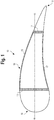
- FIG. 1 a cross-sectional view of an aircraft wing 10 is depicted schematically along a longitudinal axis "a-a", oriented along a general direction of flight.
- the wing 10 includes an interior forward wing spar 12, an interior rear wing spar 14, and top and bottom exterior wing surfaces 15 and 17, respectively.
- the wing 10 includes a leading edge 16 and a trailing edge 18.
- a wing box 19 is formed and defined by the boundaries of the forward wing spar 12, the rear wing spar 14, the top wing surface 15 and bottom wing surface 17.
- the forward wing spar 12 is situated near the leading edge 16 of the wing 10, while the rear wing spar 14 is situated near the trailing edge 18 of the wing 10.
- the apparatus and methods of this disclosure focus particularly on the wing box 19, as a discreet portion of the wing 10 of FIG. 1 , the same apparatus and methods are equally applicable to applying fuselage skins to interior frames and stringers.
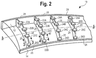
- the wing box 19 which extends laterally along an axis "b-b", is shown during its manufacture, i.e. without an upper wing panel, also known as an upper wing skin 30 ( FIG. 4 ).
- the wing box 19 includes a plurality of laterally spaced interior ribs 20, 22, 24, 26, each rib extending longitudinally, thus providing fore-aft interconnecting stiffeners, between the two wing spars 12, 14.
- ribs Although only four ribs are shown for sake of simplicity, commercial aircraft wings will typically include many times the number of ribs shown and described herein.
- each rib 20, 22, 24, 26 includes a plurality of integrally formed top brackets, also called share ties in the commercial aircraft manufacturing industry.
- the rib 20 includes brackets 20A, 20B, 20C, and 20D
- the rib 22 includes brackets 22A, 22B, 22C, and 22D, as shown.
- ribs 24 and 26 include similarly identified brackets. Referring now also to FIGS. 3 and 4 , in order to attach the upper wing skin 30 ( FIG. 4 ) to the forward and rear wing spars 12 and 14, and to the ribs 20, 22, 24, and 26, a plurality of pilot holes 28 ( FIGS.
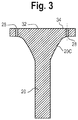
- each bracket 20A-D, 22A-D, 24A-D, and 26A-D is coterminous with, and defines the top surface 32 of, each rib 20, 22, 24, 26.
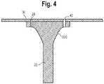
- each pilot hole 28 is a smaller hole than a fastener hole 40, as for example shown in the bracket 22C ( FIGS. 2 and 4 ), for reasons explained below.
- the wing skin 30 is ultimately placed and secured atop of the spars 12, 14, and over the upper surfaces 32 ( FIG. 3 ) of the ribs 20, 22, 24, 26 ( FIG. 2 ) for final close out the aircraft wing box 19.
- an automated end effector 50 may be employed to facilitate a one up assembly drilling operation from one side of an aircraft wing skin 30 ( FIG. 4 ) for its ultimate securement to a plurality of the afore-described wing rib and spar structures.
- the end effector 50 utilizes a system of temporary clamps to preload the mated components together prior to initiation of any actual drilling sequence.
- the end effector 50 utilizes expansible clamps 60 ( FIGS. 7 and 8 ) for application of transiently applied clamping forces between the mated components for the drilling of fastener holes 40.
- the clamps may be inserted into the pilot holes 28, in preparation for installation of actual fasteners (not shown). Physical installation of the fasteners may occur in a follow-up sequence at a different assembly station, neither shown nor part of this disclosure.
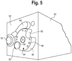
- the face 58 of the end effector 50 incorporates a vacuum chute 44 designed for removal of cutting debris including dust and chips from the drilling process.
- An expansible clamp holster 54 is configured to hold various sizes of the expansible clamps 60, which are contained in various sized apertures 46. Different sized clamps 60 are needed for accommodating variable thickness of an aircraft skin, which may have a thickness at an inboard edge of the wing box 19 that may be greater than five times the thickness at an outboard edge.
- the expansible clamp holster 54 is rotatable, as well as indexable, so as to be able to sequentially dispense variously sized expansible clamps 60, and to then rotate one of a pair of notches 56 ( FIGS.
- the installer/remover mechanism 68 is designed to insert and torque, and to later untorque and remove, an expansible clamp 60 in serial fashion, as described below.
- the multiple sized apertures 46 contain clamps 60 in a variety of sizes, such as Centrix® brand single-sided expansible clamp available in multiple sizes, and sold by Centrex, LLC of Kent, Washington, USA (www.centrix-llc.com).
- the three-dimensional holster 54 is spaced from the drilling nose 52 ( FIGS. 5 and 6 ), and both the holster 54 and the drilling nose extend from the face 58 of the end effector 50.
- the drilling nose 52 is designed to hold a drill bit 96 (of a type shown in FIG. 9 ).
- the end effector 50 may be programmed to identify an initial pilot hole 28 adjacent an initial desired fastener hole location.
- the expansible clamp holster 54 can then be indexed to position one of the notches 56 over the expansible clamp installer/remover mechanism 68.
- the mechanism 68 then sequentially inserts an expansible clamp 60 retrieved from an aperture 46 of the holster 54 into a pre-drilled pilot hole 28 ( FIGS. 2 and 3 ) adjacent the initial fastener hole location.
- the mechanism 68 then firmly installs the inserted expansible clamp 60 by torquing a fastener head 66 ( FIG. 8 ) of the expansible clamp 60, thus rotating an internal threaded bolt 64 of the clamp, until an insertion end 62 thereof expands to provide a predetermined clamp force between the mating components (e.g. skin 30 and spar 12).
- the end effector 50 is programmed to drill a set of fastener holes in predetermined locations most adjacent, i.e., immediately surrounding, the temporarily installed expansible clamp 60. Thereafter, the end effector untorques and removes the expansible clamp 60, and successively indexes to a next position to replicate identical steps for continued drilling of multiple fastener holes.
- the holster 54 is modular, and removable for cleaning and reloading.
- the predetermined clamping force provided by the expansible clamp 60 will at least equal the drilling force required to create the fastener hole.
- Such clamping forces have been determined to be sufficient to avoid creation of burrs between mated components, which disrupts integrity of the component interface and requires subsequent panel separations for deburring, cleaning, and sealing.
- steps of cleaning and sealing of the panel and its mating rib and/or spar structures would occur in advance of any given one up assembly drilling operation; i.e., prior to actual drilling of a wing skin and its mating the rib and spar structures, for example.
- a camera 70 may be included as part of a programmable vision system (not shown) to facilitate programmed movements of the end effector 50 over the wing box 19.
- various hydraulic and/or pneumatic lines 72, 74, 76 and 78 may be included for controlling various operational aspects/functions of the end effector 50.
- a system of end effectors 80, 82, 84 may be provided to drill fastener holes in forward wing spar and rib bracket areas of the wing box 19, while another system of end effectors 86, 88, 90, 92 may be provided to similarly work simultaneously over rear wing spar and rib bracket areas of the wing box 19.
- Each of the end effectors have drill bits 96 that can be managed by a computer database and operating program (neither shown).
- mated components may be formed of fiber composite materials as well as of metals, such as aluminum alloys.
- the structures may have configurations and shapes, and the processes involved may have movements, and sequences, other than ones herein described, and the disclosure may be applicable to potentially other environments, not mentioned nor suggested herein.
- the disclosed method could be expanded to include insertion and use of expansible fasteners 60 in some of the fastener holes 40, if desired, and of course after such holes 40 have been drilled during the course of a one up assembly process.
- the disclosure presents specific structures in forms as herein depicted, numerous variations of the disclosed structures may be envisioned for use in manufacture of various alternative embodiments.
Landscapes
- Engineering & Computer Science (AREA)
- Mechanical Engineering (AREA)
- Manufacturing & Machinery (AREA)
- Aviation & Aerospace Engineering (AREA)
- Robotics (AREA)
- General Engineering & Computer Science (AREA)
- Transportation (AREA)
- Drilling And Boring (AREA)
- Perforating, Stamping-Out Or Severing By Means Other Than Cutting (AREA)
- Automatic Assembly (AREA)
- Connection Of Plates (AREA)
Abstract
Description
- The present disclosure relates generally to apparatus configured and programed to drill and secure exterior panels, such as aircraft skins, to connective structures such as frames, stringers, ribs and/or spars, and more specifically to end effectors designed to facilitate so-called "one up assembly" drilling; i.e., without requiring separation of such paired components for deburring, cleaning, and/or sealing after drilling fastener holes through the components.
- Commercial aircraft manufacturing has historically been labor intensive, and thus expensive. As such, there is constant motivation for aircraft manufacturers to develop less costly procedures and techniques. One such initiative concerns assembly of exterior aircraft wing panels also called wing skins, to interior ribs and/or spar structures of aircraft. For example, although many techniques have been utilized in the manufacture of aircraft wings, and particularly in so-called final "close out" attachment of wing skins to wing ribs and/or spar structures, most such techniques continue to be burdened by time-consuming manual drilling, cleaning, and sealing processes.
- For example, one approach involves use of handheld drills and separate manual applications of transient clamp loads in strategic places to avoid having to separate and deburr, clean, and seal the panels and ribs, spars, and/or other connective structures after drilling holes for receiving fasteners during close out. Although this approach has met with success, it remains more tedious and time-consuming than desired.
- In a one form of the disclosure, an end effector is adapted for a one up assembly to secure a pair of components including a panel under clamp loads sufficient to avoid in-process separation of the panel from its paired component for deburring. The end effector includes an automated drilling head having a drill and an expansible clamp dispenser adapted to insert, expand, and remove expansible clamps into and out of various pre-drilled pilot holes during a final drilling operation, prior to fastening the panel and its paired component together. The expansible clamp dispenser assures tight securement of the panel and its paired component, under temporarily applied predetermined clamping forces between the panel and component during each instance of automated drilling of a fastener hole.
- In another form of the disclosure, a system of using a plurality of electronically programmable end effectors is provided; each end effector including a drilling head having a drill, and an expansible clamp dispenser configured to insert, expand, and remove expansible clamps into and out of various pre-drilled holes in a portion of an aircraft panel during a one up assembly drilling process in advance of securing the panel to a component. The system includes each end effector having an expansible clamp holster configured to supply and retrieve expansible clamps to tightly secure together a portion of the panel and paired component under predetermined forces during each instance of an automated final drilling of a fastener hole in the panel and paired component.
- In yet another form of the disclosure, a method of providing a one up assembly of an aircraft wing skin to a wing box includes steps of providing the wing skin to a wing box containing exposed wing rib and/or spar structures; pre-drilling pilot holes in the wing skin; applying the wing skin to the rib and/or spar structures; applying a programmable end effector having a drill head and an expansible clamp dispenser to the exterior of the wing skin; identifying a first pilot hole adjacent an initial fastener hole location; using the end effector dispenser to temporarily insert an expansible clamp into the first pilot hole; using the end effector to torque the expansible clamp after its insertion to achieve a predetermined force between the wing skin and rib and/or spar structures; using the end effector to drill a set of fastener holes adjacent the first pilot hole; using the end effector to untorque and remove the expansible clamp, and successively indexing the end effector to a next position to replicate the same steps for drilling additional sets of fastener holes. The method provides that fastener holes may be drilled in an aircraft wing panel and interior wing rib and/or spar structures under clamp loads sufficient to avoid in-process wing panel separations for deburring, cleaning, and sealing.
- All features, aspects, functions, and advantages disclosed herein may be achieved independently in various embodiments or may be combined in or with yet other embodiments, the details of which may be better appreciated with reference to the following description and drawings.
-
-
FIG. 1 is a schematic cross-sectional view of an aircraft wing of a type that may be used on a commercial aircraft. -
FIG. 2 is a perspective view from above of a wing box portion of the aircraft wing ofFIG. 1 , shown under construction. -
FIG. 3 is a cross-sectional view of a wing rib structure, taken along lines 3-3 ofFIG. 2 . -
FIG. 4 is a cross-sectional depiction taken along lines 4-4 ofFIG. 2 , showing a portion of a wing panel as might appear if positioned atop of the wing rib structure shown inFIG. 2 . -
FIG. 5 is a fragmentary perspective view of a working end of an automated end effector constructed in accordance with the present disclosure. -
FIG. 6 is a frontal or face view of the working end of the automated end effector depicted inFIG. 5 . -
FIG. 7 is a perspective cutaway view of a portion of the automated end effector of the present disclosure. -
FIG. 8 is a perspective view of an expansible clamp used in the automated end effector of the present disclosure. -
FIG. 9 is a perspective view of a plurality of automated end effectors utilizing the disclosed technology to drill fastener holes through preselected locations in the upper wing panel ofFIG. 4 and into the ribs and/or spars of the wing box ofFIG. 2 . -
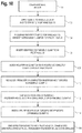
FIG. 10 is a flowchart detailing one method of application of the present disclosure. - It should be understood that referenced drawings are not necessarily to scale, and that the variously disclosed embodiments are illustrated only schematically. Aspects of the disclosed embodiments may be combined with or substituted by one another, and within various systems and environments that are neither shown nor described herein. As such, it should be understood that the following detailed description is merely exemplary, and not intended to be limiting in its application or use.
- The following detailed description is intended to provide both apparatus and methods for carrying out the disclosure. Actual scope of the disclosure is as defined by the appended claims.
- Referring initially to
FIG. 1 , a cross-sectional view of anaircraft wing 10 is depicted schematically along a longitudinal axis "a-a", oriented along a general direction of flight. Thewing 10 includes an interiorforward wing spar 12, an interiorrear wing spar 14, and top and bottom exterior wing surfaces 15 and 17, respectively. Thewing 10 includes a leading edge 16 and a trailing edge 18. Awing box 19 is formed and defined by the boundaries of theforward wing spar 12, the rear wing spar 14, the top wing surface 15 and bottom wing surface 17. Theforward wing spar 12 is situated near the leading edge 16 of thewing 10, while therear wing spar 14 is situated near the trailing edge 18 of thewing 10. Although the apparatus and methods of this disclosure focus particularly on thewing box 19, as a discreet portion of thewing 10 ofFIG. 1 , the same apparatus and methods are equally applicable to applying fuselage skins to interior frames and stringers. - Referring now to
FIG. 2 , thewing box 19, which extends laterally along an axis "b-b", is shown during its manufacture, i.e. without an upper wing panel, also known as an upper wing skin 30 (FIG. 4 ). Extending between the forward and rear laterally extendingwing spars wing box 19 includes a plurality of laterally spacedinterior ribs wing spars - For purposes of securing the
wing skin 30, eachrib rib 20 includesbrackets rib 22 includesbrackets ribs 24 and 26 include similarly identified brackets. Referring now also toFIGS. 3 and4 , in order to attach the upper wing skin 30 (FIG. 4 ) to the forward andrear wing spars ribs FIGS. 2 and3 ) are pre-drilled into thewing skin 30, thewing spars 12, 14 (FIG. 2 ), and also into an upper surface 34 (FIG. 3 ) in each of thebrackets 20A-D, 22A-D, 24A-D, and 26A-D (FIG. 2 ). Those skilled in the art will appreciate that theupper surface 34 of each bracket is coterminous with, and defines thetop surface 32 of, eachrib pilot hole 28 is a smaller hole than afastener hole 40, as for example shown in the bracket 22C (FIGS. 2 and4 ), for reasons explained below. Thewing skin 30 is ultimately placed and secured atop of thespars FIG. 3 ) of theribs FIG. 2 ) for final close out theaircraft wing box 19. - All examples in this disclosure relate to an apparatus, a method, and/or a system for securing the
wing skin 30 to thewing spars various brackets 20A-D, 22A-D, 24A-D, and 26A-D. Referring now also toFIGS. 5 ,6 , and7 , in order to avoid tedious and time consuming processes associated with use of manual tools for securing wing skins to aircraft wing structures, an automated end effector 50 (FIG. 5 ) may be employed to facilitate a one up assembly drilling operation from one side of an aircraft wing skin 30 (FIG. 4 ) for its ultimate securement to a plurality of the afore-described wing rib and spar structures. As the one up assembly process is designed to avoid post-drilling separations of thewing skin 30 from the wing ribs and spars for deburring, cleaning, and sealing of mated components intended to ultimately be fastened together, theend effector 50 utilizes a system of temporary clamps to preload the mated components together prior to initiation of any actual drilling sequence. - For this purpose, the
end effector 50 utilizes expansible clamps 60 (FIGS. 7 and8 ) for application of transiently applied clamping forces between the mated components for the drilling offastener holes 40. The clamps may be inserted into thepilot holes 28, in preparation for installation of actual fasteners (not shown). Physical installation of the fasteners may occur in a follow-up sequence at a different assembly station, neither shown nor part of this disclosure. - The
face 58 of the end effector 50 (FIGS. 5 and6 ) incorporates avacuum chute 44 designed for removal of cutting debris including dust and chips from the drilling process. Anexpansible clamp holster 54 is configured to hold various sizes of theexpansible clamps 60, which are contained in various sizedapertures 46. Different sizedclamps 60 are needed for accommodating variable thickness of an aircraft skin, which may have a thickness at an inboard edge of thewing box 19 that may be greater than five times the thickness at an outboard edge. Theexpansible clamp holster 54 is rotatable, as well as indexable, so as to be able to sequentially dispense variously sizedexpansible clamps 60, and to then rotate one of a pair of notches 56 (FIGS. 5 and6 ), situated within arounded side 48 of theholster 54, to a position to accommodate an expansible clamp installer/remover mechanism 68. The installer/remover mechanism 68 is designed to insert and torque, and to later untorque and remove, anexpansible clamp 60 in serial fashion, as described below. The multiple sizedapertures 46 containclamps 60 in a variety of sizes, such as Centrix® brand single-sided expansible clamp available in multiple sizes, and sold by Centrex, LLC of Kent, Washington, USA (www.centrix-llc.com). - The three-
dimensional holster 54 is spaced from the drilling nose 52 (FIGS. 5 and6 ), and both theholster 54 and the drilling nose extend from theface 58 of theend effector 50. Thedrilling nose 52 is designed to hold a drill bit 96 (of a type shown inFIG. 9 ). As disclosed, once a skin 30 (FIG. 4 ) is applied over the exposedribs FIG. 2 ), theend effector 50 may be programmed to identify aninitial pilot hole 28 adjacent an initial desired fastener hole location. Theexpansible clamp holster 54 can then be indexed to position one of thenotches 56 over the expansible clamp installer/remover mechanism 68. Themechanism 68 then sequentially inserts anexpansible clamp 60 retrieved from anaperture 46 of theholster 54 into a pre-drilled pilot hole 28 (FIGS. 2 and3 ) adjacent the initial fastener hole location. Themechanism 68 then firmly installs the insertedexpansible clamp 60 by torquing a fastener head 66 (FIG. 8 ) of theexpansible clamp 60, thus rotating an internal threadedbolt 64 of the clamp, until aninsertion end 62 thereof expands to provide a predetermined clamp force between the mating components (e.g. skin 30 and spar 12). - The
end effector 50 is programmed to drill a set of fastener holes in predetermined locations most adjacent, i.e., immediately surrounding, the temporarily installedexpansible clamp 60. Thereafter, the end effector untorques and removes theexpansible clamp 60, and successively indexes to a next position to replicate identical steps for continued drilling of multiple fastener holes. - In the disclosed embodiments, the
holster 54 is modular, and removable for cleaning and reloading. Ideally, the predetermined clamping force provided by theexpansible clamp 60 will at least equal the drilling force required to create the fastener hole. Such clamping forces have been determined to be sufficient to avoid creation of burrs between mated components, which disrupts integrity of the component interface and requires subsequent panel separations for deburring, cleaning, and sealing. Finally, it will be appreciated that steps of cleaning and sealing of the panel and its mating rib and/or spar structures would occur in advance of any given one up assembly drilling operation; i.e., prior to actual drilling of a wing skin and its mating the rib and spar structures, for example. - The disclosed system of using a rotary
expansible clamp holster 54, entirely contained within theend effector 50, to both dispense and retrieve temporary expansible clamps 60, assures a tight mating of wing skin, rib, and spar components under predetermined transiently applied forces during each instance of automated drilling of fastener holes through the mated structures. - Continuing reference to
FIG. 6 , acamera 70 may be included as part of a programmable vision system (not shown) to facilitate programmed movements of theend effector 50 over thewing box 19. In addition, various hydraulic and/orpneumatic lines end effector 50. - Referring to
FIG. 9 , a system ofend effectors wing box 19, while another system ofend effectors wing box 19. Each of the end effectors havedrill bits 96 that can be managed by a computer database and operating program (neither shown). -
- A) Use of Centrix® brand single-sided expansible clamps, having sizes between 1/16 and 1 inch, with load ratings of up to 2,000 lbs. of clamping force.
- B) Pilot holes are at least 1/16 inch bore sized.
- C) Each share tie or
bracket 20A-D, 22A-D, 24A-D, and 26A-D (FIG. 2 ) includes at least one pre-drilled pilot hole, and theupper bracket surface 34 has a surface area of at least 10 square inches. - D) Each fastener hole diameter is at least 3/16 inch.
- Referring also now to the flowchart of
FIG. 10 , the following steps may be implemented for a one up assembly drilling operation, in accordance with the above disclosure: - 1) The interior surface of a
skin 30 is first cleaned, and a sealing material is applied. - 2) The
skin 30 is next applied over the exposedribs FIG. 2 ). - 3) The
end effector 50 is programmed for the particular size and configuration of thewing box 19, and identifies an initialpre-drilled pilot hole 28 adjacent an undrilled location of aninitial fastener hole 40, and inserts an appropriately sizedexpansible clamp 60 into thepilot hole 28. - 4) The
holster 54 is next indexed so as to position one of thenotches 56 directly over the installer/remover 68. - 5) The
end effector 50 inserts an identified expansible clamp 60 (e.g., one 1/16 inch Centrix® brand single-sided expansible clamp) into thepilot hole 28 of bothskin 30 and a bracket, for example, for purpose of clamping those mating components tightly together. - 6) The installer/
remover 68 then completes insertion and torques the insertedexpansible clamp 60 to secure theskin 30 and the bracket together under a predetermined clamp load. - 7) The
end effector 50 then moves over the surface of theskin 30 andbracket 22B, in accordance with a predetermined drilling program, and after drilling the initialpermanent hole 40, sequentially drills additional fastener holes 40 (e.g. sized 3/16 to 5/16 inch) through both the skin and bracket; e.g., in at least two predetermined locations, including the initial one, all adjacent theexpansible clamp 60; i.e., within a several inch radius of theclamp 60. - 8) After the fastener holes are drilled, the
end effector 50 is indexed to position the installer/remover 68 over theexpansible clamp 60, and theinstaller remover 68 then untorques and removes theexpansible clamp 60. - 9) Next the
end effector 50 moves over the surface of theskin 30 to anew pilot hole 28 in either another skin tie or in either spar 12 or spar 14 (FIG. 2 ), and the steps are replicated until all preprogrammed fastener holes are drilled in thewing box 19. - 10) Finally, the
wing box 19 is transferred to a separate assembly station for installation of actual fasteners. For expediting the transfer, some of the Centrix® brand single-sided expansible clamps may be left in place in several of the holes. - Further, the disclosure comprises embodiments according to the following clauses:
- Clause 1. An end effector adapted to secure and drill through a pair of components in a one up assembly under clamp loads sufficient to avoid separation of the components for deburring after drilling, the end effector comprising:
- an automated drilling head including a drill, and an expansible clamp dispenser configured to insert, expand, and remove expansible clamps into and out of various pre-drilled pilot holes in the components during a final drilling of fastener holes in the components;
- wherein the expansible clamp dispenser assures tight securement of a selective portion of the components under temporarily applied predetermined clamping forces during each instance of automated drilling of fastener holes in the components.
- Clause 2. The end effector of Clause 1, wherein the expansible clamp dispenser comprises a holster configured to selectively supply and retrieve a plurality of expansible clamps during the final drilling.
-
Clause 3. The end effector of Clause 1, wherein the end effector is applied only to one side of the pair of components. - Clause 4. The end effector of Clause 1, wherein the end effector is an automated machine.
- Clause 5. The end effector of Clause 1, wherein one of the components is a panel.
- Clause 6. The end effector of Clause 1, wherein the end effector is electronically programmable for locating expansible clamp and fastener positions during final drilling of the components.
- Clause 7. The end effector of Clause 1, wherein the holster is modular and removable for cleaning and reloading.
- Clause 8. The end effector of Clause 2, wherein the holster is spaced from the drill, and wherein the holster is indexable, and fully automated.
- Clause 9. The end effector of
Clause 3, wherein the end effector includes an electronic vision camera for accurate positioning and movement of the end effector over the panel side of the components. -
Clause 10. A system of using a plurality of electronically programmable end effectors, each end effector including a drilling head having a drill, and an expansible clamp dispenser configured to insert, expand, and remove expansible clamps into and out of various pre-drilled holes in a portion of an aircraft panel during a one up assembly for drilling of fastener holes in the panel and an associated component, the system comprising:- each end effector having a holster configured to supply and retrieve expansible clamps into the drilling head to tightly secure together a portion of the aircraft panel and the associated component under a predetermined force during each instance of an automated final drilling of a fastener hole in the aircraft panel and associated component.
- Clause 11. The system of using the plurality of the electronically programmable end effectors of
Clause 10, wherein each holster is configured to selectively supply and retrieve the expansible clamps during the one up assembly for final drilling. -
Clause 12. The system of using the plurality of the electronically programmable end effectors ofClause 10, wherein each end effector is applied to only an exterior panel side of the components. - Clause 13. The system of using the plurality of the electronically programmable end effectors of
Clause 10, wherein each end effector is an automated machine. -
Clause 14. The system of using the plurality of the electronically programmable end effectors ofClause 10, wherein the aircraft panel is an aircraft wing or fuselage panel. - Clause 15. The system of using the plurality of the electronically programmable end effectors of
Clause 14, wherein each end effector is configured for locating pre-drilled expansible clamp and fastener positions on a portion of a wing or fuselage panel during securement of the panel to a rib, spar, frame, or stringer. - Clause 16. The system of using the plurality of the electronically programmable end effectors of
Clause 10, wherein each holster is modular and removable for cleaning and reloading. - Clause 17. The system of using the plurality of the electronically programmable end effectors of Clause 11, wherein each holster is spaced from the drill, and wherein each holster is indexable, and fully automated.
- Clause 18. The system of using the plurality of the electronically programmable end effectors of
Clause 14, wherein each end effector includes an electronic vision camera for accurate positioning and movement of the end effector over an exterior side of the wing panel. -
Clause 19. A method of providing a one up assembly of an aircraft wing skin to a plurality of wing rib and/or spar structures, the method comprising the steps of:- providing a wing skin and an aircraft wing box having exposed wing rib and/or spar structures;
- pre-drilling pilot holes in the wing skin;
- applying the wing skin to the wing rib and/or spar structures;
- applying a programmable end effector having a drill head and an expansible clamp dispenser to the exterior of the wing skin;
- using the end effector to identify a first pilot hole in the wing skin adjacent an initial fastener hole location for installation of a first expansible clamp;
- using the end effector dispenser to temporarily insert an expansible clamp into the first pilot hole;
- using the end effector to torque the expansible clamp after insertion to achieve a predetermined force between the wing skin and rib and/or spar structures;
- identifying additional desired locations of fastener holes immediately adjacent the first pilot hole;
- using the end effector to drill a first set of fastener holes immediately adjacent the first pilot hole;
- using the end effector to untorque and remove the expansible clamp;
- successively indexing the end effector to a next position to replicate the same steps for drilling additional sets of fastener holes in next desired locations;
- whereby an aircraft wing panel may be secured to an interior wing rib and/or spar structure and drilled under a clamp load sufficient to avoid in-process wing panel separations for deburring, cleaning, and sealing.
-
Clause 20. The method ofClause 19, further including steps of cleaning and sealing the wing panel prior to installation of the wing panel over the wing rib structures.
- Finally, mated components may be formed of fiber composite materials as well as of metals, such as aluminum alloys. Moreover, the structures may have configurations and shapes, and the processes involved may have movements, and sequences, other than ones herein described, and the disclosure may be applicable to potentially other environments, not mentioned nor suggested herein. For example, the disclosed method could be expanded to include insertion and use of
expansible fasteners 60 in some of the fastener holes 40, if desired, and of course aftersuch holes 40 have been drilled during the course of a one up assembly process. Further, although the disclosure presents specific structures in forms as herein depicted, numerous variations of the disclosed structures may be envisioned for use in manufacture of various alternative embodiments.
Claims (11)
- An end effector (50) adapted to secure and drill through a pair of components in a one up assembly under clamp loads sufficient to avoid separation of the components for deburring after drilling, the end effector (50) comprising:an automated drilling head including a drill, and an expansible clamp (60) dispenser configured to insert, expand, and remove expansible clamps (60) into and out of various pre-drilled pilot holes (28) in the components during a final drilling of fastener holes (40) in the components;wherein the expansible clamp (60) dispenser assures tight securement of a selective portion of the components under temporarily applied predetermined clamping forces during each instance of automated drilling of fastener holes (40) in the components.
- The end effector (50) of claim 1, wherein the expansible clamp (60) dispenser comprises a holster (54) configured to selectively supply and retrieve a plurality of expansible clamps (60) during the final drilling.
- The end effector (50) of claims 1 or 2, wherein the end effector (50) is applied only to one side of the pair of components.
- The end effector (50) of any one of claims 1-3, wherein the end effector (50) is an automated machine.
- The end effector (50) of any one of claims 1-4, wherein one of the components is a panel.
- The end effector (50) of any one of claims 1-5, wherein the end effector (50) is electronically programmable for locating expansible clamp (60) and fastener positions during final drilling of the components.
- The end effector (50) of any one of claims 1-6, wherein the holster (54) is modular and removable for cleaning and reloading.
- The end effector (50) of claim 2, wherein the holster (54) is spaced from the drill, and wherein the holster (54) is indexable, and fully automated.
- The end effector (50) of claim 3, wherein the end effector (50) includes an electronic vision camera for accurate positioning and movement of the end effector (50) over the panel side of the components.
- A method of providing a one up assembly of an aircraft wing skin (30) to a plurality of wing rib and/or spar structures, the method comprising the steps of:providing a wing skin (30) and an aircraft wing box having exposed wing rib and/or spar structures;pre-drilling pilot holes (28) in the wing skin (30);applying the wing skin (30) to the wing rib and/or spar structures;applying a programmable end effector (50) having a drill head and an expansible clamp (60) dispenser to the exterior of the wing skin (30);using the end effector (50) to identify a first pilot hole in the wing skin (30) adjacent an initial fastener hole (40) location for installation of a first expansible clamp (60);using the end effector (50) dispenser to temporarily insert an expansible clamp (60) into the first pilot hole;using the end effector (50) to torque the expansible clamp (60) after insertion to achieve a predetermined force between the wing skin (30) and rib and/or spar structures;identifying additional desired locations of fastener holes (40) immediately adjacent the first pilot hole;using the end effector (50) to drill a first set of fastener holes (40) immediately adjacent the first pilot hole;using the end effector (50) to untorque and remove the expansible clamp (60);successively indexing the end effector (50) to a next position to replicate the same steps for drilling additional sets of fastener holes (40) in next desired locations;whereby an aircraft wing panel may be secured to an interior wing rib and/or spar structure and drilled under a clamp load sufficient to avoid in-process wing panel separations for deburring, cleaning, and sealing.
- The method of claim 10, further including steps of cleaning and sealing the wing panel prior to installation of the wing panel over the wing rib structures.
Applications Claiming Priority (1)
| Application Number | Priority Date | Filing Date | Title |
|---|---|---|---|
| US15/333,915 US11370036B2 (en) | 2016-10-25 | 2016-10-25 | One up assembly aircraft panel drilling system |
Publications (1)
| Publication Number | Publication Date |
|---|---|
| EP3315230A1 true EP3315230A1 (en) | 2018-05-02 |
Family
ID=59738165
Family Applications (1)
| Application Number | Title | Priority Date | Filing Date |
|---|---|---|---|
| EP17187407.6A Pending EP3315230A1 (en) | 2016-10-25 | 2017-08-23 | End effector and method of providing a one up assembly |
Country Status (5)
| Country | Link |
|---|---|
| US (1) | US11370036B2 (en) |
| EP (1) | EP3315230A1 (en) |
| JP (1) | JP7177586B2 (en) |
| CN (1) | CN107971519B (en) |
| RU (1) | RU2748241C2 (en) |
Cited By (1)
| Publication number | Priority date | Publication date | Assignee | Title |
|---|---|---|---|---|
| DE102020110770B3 (en) | 2020-04-21 | 2021-09-23 | Fraunhofer-Gesellschaft zur Förderung der angewandten Forschung eingetragener Verein | Device and method for drilling through a component and a workpiece |
Families Citing this family (11)
| Publication number | Priority date | Publication date | Assignee | Title |
|---|---|---|---|---|
| US10981277B2 (en) * | 2018-12-17 | 2021-04-20 | The Boeing Company | Shank-fastener apparatuses and methods for joining panels |
| CN110125455B (en) * | 2019-05-27 | 2020-06-02 | 清华大学 | Method for optimizing drill bit pose in robot drilling |
| CN113000880B (en) * | 2019-12-20 | 2023-05-30 | 中核建中核燃料元件有限公司 | An automatic drilling method for nuclear power control rod components |
| CN111438392B (en) * | 2020-05-15 | 2024-06-14 | 沈阳飞机工业(集团)有限公司 | Round flap positioning drilling tool and application method thereof |
| CN111687447B (en) * | 2020-06-23 | 2022-01-28 | 泰州鸿材科技有限公司 | Ultra-thin wall metal filters pipe fitting bottom system hole equipment |
| CN112975794B (en) * | 2021-02-22 | 2022-01-04 | 浙江大学 | Positioning and clamping device for outer wing of airplane |
| CN113245598B (en) * | 2021-04-30 | 2024-07-16 | 长沙五七一二飞机工业有限责任公司 | Adjustable drilling jig device for copying hole sites of old parts and use method |
| DE102022206368A1 (en) * | 2022-06-24 | 2024-01-04 | Thyssenkrupp Ag | Application device with integrated drilling unit |
| US11851213B1 (en) * | 2022-10-14 | 2023-12-26 | The Boeing Company | Methods and structural gap filler for one-up assembly |
| EP4400429A1 (en) * | 2023-01-13 | 2024-07-17 | Airbus Operations Limited | Method of manufacturing an aircraft assembly |
| US12005537B1 (en) | 2023-04-11 | 2024-06-11 | Lockheed Martin Corporation | Fastener removal assembly for automated temporary fastener removal |
Citations (7)
| Publication number | Priority date | Publication date | Assignee | Title |
|---|---|---|---|---|
| EP0338117A2 (en) * | 1988-04-19 | 1989-10-25 | Aeroflex Technologies, Inc. | Improved riveting process and apparatus |
| US5050288A (en) * | 1989-12-15 | 1991-09-24 | The Boeing Company | Dynamic dimensional control matrix system |
| US6098260A (en) * | 1996-12-13 | 2000-08-08 | Mcdonnell Douglas Corporation | Rivet fastening system for radial fuselage joints |
| US20030034355A1 (en) * | 2001-08-16 | 2003-02-20 | Bloch Daniel D. | Portable automatic fastener delivery system |
| US6949057B2 (en) * | 2003-09-02 | 2005-09-27 | The Boeing Company | Multi-function end effector |
| EP2221151A2 (en) * | 2009-02-24 | 2010-08-25 | The Boeing Company | Autonomous robotic assembly system comprising a plurality of mobile robotic machines and a wireless communication system |
| WO2016104700A1 (en) * | 2014-12-26 | 2016-06-30 | 川崎重工業株式会社 | Machining method and system |
Family Cites Families (13)
| Publication number | Priority date | Publication date | Assignee | Title |
|---|---|---|---|---|
| US1949007A (en) | 1931-03-31 | 1934-02-27 | Boeing Co | Alignment jig |
| US7048266B2 (en) * | 2002-10-17 | 2006-05-23 | Monogram Aerospace Fasteners, Inc. | Device and method for temporarily fastening a plurality of workpieces in response to the introduction of pressurized fluid |
| US20060067783A1 (en) * | 2004-09-25 | 2006-03-30 | Garry Tsaur | Dual chamber applicator |
| US8006362B2 (en) * | 2007-04-06 | 2011-08-30 | The Boeing Company | Method and apparatus for installing fasteners |
| US8209865B2 (en) * | 2009-06-04 | 2012-07-03 | Lockheed Martin Corporation | Method of manufacturing aircraft using temporary fasteners |
| US8805575B1 (en) * | 2011-07-11 | 2014-08-12 | The Boeing Company | Methods and apparatus for delivering fasteners |
| GB201120707D0 (en) * | 2011-12-01 | 2012-01-11 | Airbus Operations Ltd | Leading edge structure |
| US9102019B2 (en) * | 2012-12-21 | 2015-08-11 | Embraer S.A. | Process for joining aircraft structural components |
| FR3014969B1 (en) * | 2013-12-16 | 2016-01-29 | Lisi Aerospace | TEMPORARY FIXATION |
| US9687946B2 (en) * | 2014-04-18 | 2017-06-27 | The Boeing Company | Automated apparatus for use in selectively installing temporary fasteners in an assembly |
| US10427254B2 (en) * | 2014-04-30 | 2019-10-01 | The Boeing Company | Flexible manufacturing for aircraft structures |
| US10071427B2 (en) * | 2014-09-05 | 2018-09-11 | Mazak Corporation | Vertical machine tool apparatus and method |
| US9789609B2 (en) * | 2015-02-25 | 2017-10-17 | The Boeing Company | Substantially simultaneous manufacturing functions |
-
2016
- 2016-10-25 US US15/333,915 patent/US11370036B2/en active Active
-
2017
- 2017-08-22 RU RU2017129751A patent/RU2748241C2/en active
- 2017-08-23 EP EP17187407.6A patent/EP3315230A1/en active Pending
- 2017-09-14 CN CN201710824719.0A patent/CN107971519B/en active Active
- 2017-09-28 JP JP2017187775A patent/JP7177586B2/en active Active
Patent Citations (8)
| Publication number | Priority date | Publication date | Assignee | Title |
|---|---|---|---|---|
| EP0338117A2 (en) * | 1988-04-19 | 1989-10-25 | Aeroflex Technologies, Inc. | Improved riveting process and apparatus |
| US5050288A (en) * | 1989-12-15 | 1991-09-24 | The Boeing Company | Dynamic dimensional control matrix system |
| US6098260A (en) * | 1996-12-13 | 2000-08-08 | Mcdonnell Douglas Corporation | Rivet fastening system for radial fuselage joints |
| US20030034355A1 (en) * | 2001-08-16 | 2003-02-20 | Bloch Daniel D. | Portable automatic fastener delivery system |
| US6949057B2 (en) * | 2003-09-02 | 2005-09-27 | The Boeing Company | Multi-function end effector |
| EP2221151A2 (en) * | 2009-02-24 | 2010-08-25 | The Boeing Company | Autonomous robotic assembly system comprising a plurality of mobile robotic machines and a wireless communication system |
| WO2016104700A1 (en) * | 2014-12-26 | 2016-06-30 | 川崎重工業株式会社 | Machining method and system |
| US20180001484A1 (en) * | 2014-12-26 | 2018-01-04 | Kawasaki Jukogyo Kabushiki Kaisha | Machining method and machining system |
Cited By (1)
| Publication number | Priority date | Publication date | Assignee | Title |
|---|---|---|---|---|
| DE102020110770B3 (en) | 2020-04-21 | 2021-09-23 | Fraunhofer-Gesellschaft zur Förderung der angewandten Forschung eingetragener Verein | Device and method for drilling through a component and a workpiece |
Also Published As
| Publication number | Publication date |
|---|---|
| US11370036B2 (en) | 2022-06-28 |
| RU2017129751A (en) | 2019-02-22 |
| CN107971519A (en) | 2018-05-01 |
| CN107971519B (en) | 2021-10-15 |
| US20180111701A1 (en) | 2018-04-26 |
| JP2018111194A (en) | 2018-07-19 |
| RU2017129751A3 (en) | 2020-12-29 |
| JP7177586B2 (en) | 2022-11-24 |
| BR102017021382A2 (en) | 2018-05-15 |
| RU2748241C2 (en) | 2021-05-21 |
Similar Documents
| Publication | Publication Date | Title |
|---|---|---|
| US11370036B2 (en) | One up assembly aircraft panel drilling system | |
| DE69829255T2 (en) | Portable fastening system for use in the assembly of mechanical structures | |
| EP2745955B1 (en) | Process for joining aircraft structural components | |
| US9879704B2 (en) | Systems and methods for assembling aircraft wing skins | |
| US7774918B2 (en) | Drilling apparatus and method | |
| US9656319B2 (en) | Positioning system for electromagnetic riveting | |
| JP6920055B2 (en) | One-sided fastener assembly and its installation method and system | |
| EP2332669A1 (en) | Multi-functional device and method for performing automatic riveting by means of numerical control | |
| EP3354407B1 (en) | Fastener-installation systems and methods | |
| CA2408779C (en) | Integration of self-locating feature into detail parts | |
| GB2276600A (en) | Manufacture of aircraft wings. | |
| BR102017021382B1 (en) | TERMINAL OPERATOR, AND, METHOD FOR PROVIDING A SIMPLE ASSEMBLY OF AN AIRCRAFT WING SKINNER | |
| EP3216540B1 (en) | Limited access fastener installation | |
| CN112743344A (en) | Automated rivet apparatus and method for automated installation of half-tubular fastener rivets | |
| EP3730747B1 (en) | Joining components | |
| JP7636896B2 (en) | Low-cost, high-performance multi-head drill and fill machine | |
| EP4663324A1 (en) | Fastener installation assembly, an end-effector tool, and a method | |
| Rufin¹ et al. | Fatigue Considerations in the Development and Implementation of Mechanical Joining Processes for Commercial Airplane Structures | |
| Salour et al. | Flexible Assembly System | |
| JP2021107213A (en) | Joint joining aircraft wing to aircraft body | |
| Marguet et al. | New self-removable temporary fasteners for orbital junction | |
| Cibuel et al. | One-Sided assembly with mobile platforms |
Legal Events
| Date | Code | Title | Description |
|---|---|---|---|
| PUAI | Public reference made under article 153(3) epc to a published international application that has entered the european phase |
Free format text: ORIGINAL CODE: 0009012 |
|
| STAA | Information on the status of an ep patent application or granted ep patent |
Free format text: STATUS: REQUEST FOR EXAMINATION WAS MADE |
|
| 17P | Request for examination filed |
Effective date: 20170823 |
|
| AK | Designated contracting states |
Kind code of ref document: A1 Designated state(s): AL AT BE BG CH CY CZ DE DK EE ES FI FR GB GR HR HU IE IS IT LI LT LU LV MC MK MT NL NO PL PT RO RS SE SI SK SM TR |
|
| AX | Request for extension of the european patent |
Extension state: BA ME |
|
| RBV | Designated contracting states (corrected) |
Designated state(s): AL AT BE BG CH CY CZ DE DK EE ES FI FR GB GR HR HU IE IS IT LI LT LU LV MC MK MT NL NO PL PT RO RS SE SI SK SM TR |
|
| STAA | Information on the status of an ep patent application or granted ep patent |
Free format text: STATUS: EXAMINATION IS IN PROGRESS |
|
| 17Q | First examination report despatched |
Effective date: 20200708 |
|
| RAP3 | Party data changed (applicant data changed or rights of an application transferred) |
Owner name: THE BOEING COMPANY |