EP3315213B1 - Component used in air conditioner and air conditioner having same - Google Patents
Component used in air conditioner and air conditioner having same Download PDFInfo
- Publication number
- EP3315213B1 EP3315213B1 EP16842176.6A EP16842176A EP3315213B1 EP 3315213 B1 EP3315213 B1 EP 3315213B1 EP 16842176 A EP16842176 A EP 16842176A EP 3315213 B1 EP3315213 B1 EP 3315213B1
- Authority
- EP
- European Patent Office
- Prior art keywords
- coating
- component
- upper coating
- air conditioner
- case
- Prior art date
- Legal status (The legal status is an assumption and is not a legal conclusion. Google has not performed a legal analysis and makes no representation as to the accuracy of the status listed.)
- Not-in-force
Links
Images





Classifications
-
- F—MECHANICAL ENGINEERING; LIGHTING; HEATING; WEAPONS; BLASTING
- F24—HEATING; RANGES; VENTILATING
- F24F—AIR-CONDITIONING; AIR-HUMIDIFICATION; VENTILATION; USE OF AIR CURRENTS FOR SCREENING
- F24F11/00—Control or safety arrangements
- F24F11/30—Control or safety arrangements for purposes related to the operation of the system, e.g. for safety or monitoring
- F24F11/48—Control or safety arrangements for purposes related to the operation of the system, e.g. for safety or monitoring prior to normal operation, e.g. pre-heating or pre-cooling
-
- F—MECHANICAL ENGINEERING; LIGHTING; HEATING; WEAPONS; BLASTING
- F24—HEATING; RANGES; VENTILATING
- F24F—AIR-CONDITIONING; AIR-HUMIDIFICATION; VENTILATION; USE OF AIR CURRENTS FOR SCREENING
- F24F1/00—Room units for air-conditioning, e.g. separate or self-contained units or units receiving primary air from a central station
- F24F1/0007—Indoor units, e.g. fan coil units
- F24F1/0043—Indoor units, e.g. fan coil units characterised by mounting arrangements
- F24F1/0057—Indoor units, e.g. fan coil units characterised by mounting arrangements mounted in or on a wall
-
- B—PERFORMING OPERATIONS; TRANSPORTING
- B05—SPRAYING OR ATOMISING IN GENERAL; APPLYING FLUENT MATERIALS TO SURFACES, IN GENERAL
- B05D—PROCESSES FOR APPLYING FLUENT MATERIALS TO SURFACES, IN GENERAL
- B05D5/00—Processes for applying liquids or other fluent materials to surfaces to obtain special surface effects, finishes or structures
-
- B—PERFORMING OPERATIONS; TRANSPORTING
- B05—SPRAYING OR ATOMISING IN GENERAL; APPLYING FLUENT MATERIALS TO SURFACES, IN GENERAL
- B05D—PROCESSES FOR APPLYING FLUENT MATERIALS TO SURFACES, IN GENERAL
- B05D5/00—Processes for applying liquids or other fluent materials to surfaces to obtain special surface effects, finishes or structures
- B05D5/08—Processes for applying liquids or other fluent materials to surfaces to obtain special surface effects, finishes or structures to obtain an anti-friction or anti-adhesive surface
-
- B—PERFORMING OPERATIONS; TRANSPORTING
- B05—SPRAYING OR ATOMISING IN GENERAL; APPLYING FLUENT MATERIALS TO SURFACES, IN GENERAL
- B05D—PROCESSES FOR APPLYING FLUENT MATERIALS TO SURFACES, IN GENERAL
- B05D5/00—Processes for applying liquids or other fluent materials to surfaces to obtain special surface effects, finishes or structures
- B05D5/12—Processes for applying liquids or other fluent materials to surfaces to obtain special surface effects, finishes or structures to obtain a coating with specific electrical properties
-
- B—PERFORMING OPERATIONS; TRANSPORTING
- B05—SPRAYING OR ATOMISING IN GENERAL; APPLYING FLUENT MATERIALS TO SURFACES, IN GENERAL
- B05D—PROCESSES FOR APPLYING FLUENT MATERIALS TO SURFACES, IN GENERAL
- B05D7/00—Processes, other than flocking, specially adapted for applying liquids or other fluent materials to particular surfaces or for applying particular liquids or other fluent materials
-
- F—MECHANICAL ENGINEERING; LIGHTING; HEATING; WEAPONS; BLASTING
- F04—POSITIVE - DISPLACEMENT MACHINES FOR LIQUIDS; PUMPS FOR LIQUIDS OR ELASTIC FLUIDS
- F04D—NON-POSITIVE-DISPLACEMENT PUMPS
- F04D25/00—Pumping installations or systems
- F04D25/02—Units comprising pumps and their driving means
- F04D25/08—Units comprising pumps and their driving means the working fluid being air, e.g. for ventilation
-
- F—MECHANICAL ENGINEERING; LIGHTING; HEATING; WEAPONS; BLASTING
- F24—HEATING; RANGES; VENTILATING
- F24F—AIR-CONDITIONING; AIR-HUMIDIFICATION; VENTILATION; USE OF AIR CURRENTS FOR SCREENING
- F24F1/00—Room units for air-conditioning, e.g. separate or self-contained units or units receiving primary air from a central station
- F24F1/0007—Indoor units, e.g. fan coil units
- F24F1/0059—Indoor units, e.g. fan coil units characterised by heat exchangers
- F24F1/0063—Indoor units, e.g. fan coil units characterised by heat exchangers by the mounting or arrangement of the heat exchangers
-
- F—MECHANICAL ENGINEERING; LIGHTING; HEATING; WEAPONS; BLASTING
- F24—HEATING; RANGES; VENTILATING
- F24F—AIR-CONDITIONING; AIR-HUMIDIFICATION; VENTILATION; USE OF AIR CURRENTS FOR SCREENING
- F24F1/00—Room units for air-conditioning, e.g. separate or self-contained units or units receiving primary air from a central station
- F24F1/0007—Indoor units, e.g. fan coil units
- F24F1/0071—Indoor units, e.g. fan coil units with means for purifying supplied air
- F24F1/0073—Indoor units, e.g. fan coil units with means for purifying supplied air characterised by the mounting or arrangement of filters
-
- F—MECHANICAL ENGINEERING; LIGHTING; HEATING; WEAPONS; BLASTING
- F24—HEATING; RANGES; VENTILATING
- F24F—AIR-CONDITIONING; AIR-HUMIDIFICATION; VENTILATION; USE OF AIR CURRENTS FOR SCREENING
- F24F13/00—Details common to, or for air-conditioning, air-humidification, ventilation or use of air currents for screening
- F24F13/08—Air-flow control members, e.g. louvres, grilles, flaps or guide plates
-
- F—MECHANICAL ENGINEERING; LIGHTING; HEATING; WEAPONS; BLASTING
- F24—HEATING; RANGES; VENTILATING
- F24F—AIR-CONDITIONING; AIR-HUMIDIFICATION; VENTILATION; USE OF AIR CURRENTS FOR SCREENING
- F24F13/00—Details common to, or for air-conditioning, air-humidification, ventilation or use of air currents for screening
- F24F13/20—Casings or covers
-
- F—MECHANICAL ENGINEERING; LIGHTING; HEATING; WEAPONS; BLASTING
- F24—HEATING; RANGES; VENTILATING
- F24F—AIR-CONDITIONING; AIR-HUMIDIFICATION; VENTILATION; USE OF AIR CURRENTS FOR SCREENING
- F24F13/00—Details common to, or for air-conditioning, air-humidification, ventilation or use of air currents for screening
- F24F13/30—Arrangement or mounting of heat-exchangers
-
- B—PERFORMING OPERATIONS; TRANSPORTING
- B05—SPRAYING OR ATOMISING IN GENERAL; APPLYING FLUENT MATERIALS TO SURFACES, IN GENERAL
- B05D—PROCESSES FOR APPLYING FLUENT MATERIALS TO SURFACES, IN GENERAL
- B05D1/00—Processes for applying liquids or other fluent materials
- B05D1/02—Processes for applying liquids or other fluent materials performed by spraying
- B05D1/12—Applying particulate materials
-
- C—CHEMISTRY; METALLURGY
- C01—INORGANIC CHEMISTRY
- C01P—INDEXING SCHEME RELATING TO STRUCTURAL AND PHYSICAL ASPECTS OF SOLID INORGANIC COMPOUNDS
- C01P2004/00—Particle morphology
- C01P2004/60—Particles characterised by their size
- C01P2004/64—Nanometer sized, i.e. from 1-100 nanometer
-
- F—MECHANICAL ENGINEERING; LIGHTING; HEATING; WEAPONS; BLASTING
- F24—HEATING; RANGES; VENTILATING
- F24F—AIR-CONDITIONING; AIR-HUMIDIFICATION; VENTILATION; USE OF AIR CURRENTS FOR SCREENING
- F24F2110/00—Control inputs relating to air properties
- F24F2110/50—Air quality properties
Definitions
- Dust in the air is attached to the surface of the component due to static electricity when the air passes by the component of the air conditioner.
- US 2011/315360 discloses a coating composition including hydrophobic resin particles dispersed in an aqueous medium; hydrophilic inorganic fine particles; and an oxidizing agent containing at least one of a peroxide, a perchloric acid, a chlorate, a persulfuric acid, a superphosphoric acid, and a periodate.
- the fluororesin used in the fluororesin coating according to the prior art has a size of about 1 to 2 ⁇ m, dust or particles having a size of 2 ⁇ m or more are prevented from adhering to components used in the air conditioner.
- the fluororesin coating cannot prevent fine dust or fine particles having a size of several tens to several hundreds of nm, less than 1 ⁇ m from adhering to components used in an air conditioner.
- the present disclosure has been developed in order to overcome the above drawbacks and other problems, and relates to a component used in an air conditioner that can prevent fine dust or fine particles from adhering to a surface and an air conditioner having the same.
- FIG. 1 is a cross-sectional view illustrating an air conditioner using components used in an air conditioner according to an embodiment of the present disclosure.
- an air conditioner 1 may include a case 10, a fan 20, a heat exchanger 30, and a plurality of horizontal blades 40.
- the case 10 forms the outer shape of the air conditioner 1 and accommodates and supports the fan 20, the heat exchanger 30, and the plurality of horizontal blades 40.
- the case 10 is provided with a suction grille 11 for sucking outside air into the case 10 and a discharge port 13 for discharging the sucked air to the outside.
- the suction grille 11 is formed on the upper surface and the front surface of the case 10.
- the suction grille 11 is provided with a plurality of slits through which the outside air can be sucked.
- a filter for filtering out dust or dirt contained in the outside air is disposed on the inner side of the suction grille 11.
- the discharge port 13 is formed at the lower side of the case 10, and the discharge port 13 is provided with the plurality of horizontal blades 40.
- a plurality of vertical blades may be disposed inside the case 10 behind the plurality of horizontal blades 40.
- the heat exchanger 30 is formed to perform heat exchange with the sucked air, thereby lowering the temperature of the sucked air to perform cooling or thereby raising the temperature of the sucked air to perform heating.
- the heat exchanger 30 is connected to an outdoor device (not illustrated) to perform a refrigeration cycle.
- the heat exchanger 30 is provided between the suction grille 11 and the fan 20 inside the case 10.
- the installation position of the heat exchanger 30 is not limited thereto.
- the heat exchanger 30 may be disposed between the fan 20 and the discharge port 13.
- a discharge duct 50 for guiding the air discharging from the fan 20 to the discharge port 13 may be provided inside the case 10.
- One end of the discharge duct 50 forms the discharge port 13. Accordingly, the plurality of horizontal blades 40 may be provided inside the discharge duct 50.
- the plurality of horizontal blades 40 are made of resin or plastic, are formed in flat plates or plates having a substantially arc shape cross-section, and are disposed in the width direction of the case 10 (direction perpendicular to the drawing in FIG. 1 ).
- the plurality of horizontal blades 40 may change the direction of the air flow, that is, the direction of wind, discharged to the outside of the case 10 by the fan 20 in the vertical direction.
- the plurality of vertical blades are made of resin or plastic, and may be formed in various types of flat plates.
- the plurality of vertical blades may be disposed at regular intervals in the width direction of the case 10.
- the indoor device of the air conditioner 1 as illustrated in FIG. 1 is of a wall-mounted type; however, the present disclosure is not limited thereto.
- a nano-coating described later may be formed thereon.
- a nano-coating according to an embodiment of the present disclosure may be formed on the suction grille 11, the plurality of horizontal blades 40, and the discharge port 13 of the case 10 which are in contact with the air as a passage of the air.
- the nano-coating may be formed on the entire surface of the suction grille 11.
- the nano-coating may be formed on the entire surface of the plurality of horizontal blades 40.
- the nano-coating may be formed on the surface in contact with the air.
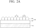
- FIGS. 2a and 2b are partial cross-sectional views conceptually illustrating a coating structure of a component used in an air conditioner according to an embodiment of the present disclosure.
- FIG. 3 is a scanning electron microscope (SEM) image of an upper coating of a component used in an air conditioner according to an embodiment of the present disclosure
- FIG. 4 is an atomic force microscope (AFM) image of an upper coating of a component used in an air conditioner according to an embodiment of the present disclosure
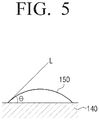
- FIG. 5 is a view illustrating a contact angle of a water droplet adhered to a nano-coating surface of a component used in an air conditioner according to an embodiment of the present disclosure.
- a component 100 used in an air conditioner may include a substrate 110 and a nano-coating 120 formed on the surface of the substrate 110.
- the substrate 110 forms the component 100 used in the air conditioner 1, and may be resin, plastic, or metal.
- the substrate 110 may be the case 10, the suction grille 11, the fan 20, the heat exchanger 30, etc. constituting the air conditioner 1 as described above.
- the nano-coating 120 is formed on the surface of the substrate 110 and includes two layers 130 and 140.
- the nano-coating 120 includes a lower coating 130 formed on the surface of the substrate 110 and an upper coating 140 formed on the upper surface of the lower coating 130.
- the thickness T1 of the lower coating 130 and the thickness T2 of the upper coating 140 is different.
- the lower coating 130 is configured to improve the bondability between the upper coating 140 and the substrate 110.
- the thickness T1 of the lower coating 130 is about 20 nm to 300 nm.
- the lower coating composition forming the lower coating 130 may include at least one of Ti, Si, and C. Silane may be used as a binder for the lower coating composition. Further, the lower coating composition may have a specific gravity of about 0.9 to 1.1 to form a lower coating by spraying using a spray gun. To this end, the lower coating composition may include an alcohol.
- the upper coating 140 functions to prevent dust or dirt from adhering to the substrate 110 by removing the static electricity of the dust or dirt that is in contact with the upper coating 140.
- the thickness T2 of the upper coating 140 is about 100 nm to 800 nm.
- the thickness T2 of the upper coating 140 is in this range, the dust adhesion prevention function of the upper coating 140 is improved and the transparency of the upper coating 140 may be improved.
- the total thickness (T1 + T2) of the upper coating 140 and the lower coating 130 is less than 1 ⁇ m, the transparency is improved and the color of the substrate 110 may be exposed as it is.
- the thickness T2 of the upper coating 140 is different from the thickness T1 of the lower coating 130.
- the thickness of the fluororesin layer is about 1 to 5 ⁇ m, the transparency is low so that the color of the substrate is not exposed as it is.
- the color of the substrate 110 may be exposed as it is.
- the upper coating 140 may be formed by spraying the upper coating composition using a spray gun in the same manner as the lower coating 130. Accordingly, a specific gravity of the upper coating composition may be about 0.9 to 1.1. To this end, the upper coating composition may include an alcohol.
- the upper coating composition may be formed such that the surface resistance of the upper coating 140 is about 10 8 ⁇ to 10 12 ⁇ .
- the electrical conductivity is increased. Therefore, when dust or dirt comes into contact with the upper coating 140, the upper coating 140 effectively absorbs static electricity of dust or dirt so that the dust or dirt does not adhere to the upper coating 140 but falls off.
- the structure in which the nanoparticles forming the upper coating are combined is illustrated in FIGS. 3 and 4 .
- the nanoparticles that make up the upper coating are bound by molecular bonding.
- the nanoparticles are bound to each other by intermolecular bonding by means of titanium Ti in an amorphous state.
- the nanoparticles may be bound to each other by the silane.
- the nanoparticles forming the upper coating 140 may be stacked in at least one layer.
- FIG. 2a schematically illustrates a case where the upper coating 140 is formed of one layer of nanoparticles 141.
- FIG. 2b illustrates a case where the nanoparticles forming the upper coating 140 are formed as a plurality of layers, in the present embodiment, four nanoparticles layers.
- the surface of the upper coating 140 means the top layer.
- the upper coating 140 is formed so that the interval P between the adjacent nanoparticles 141 located in the surface of the upper coating 140 is about 10 nm to 30 nm.
- the interval between adjacent nanoparticles 141 among the plurality of nanoparticles 141 constituting the upper coating 140 may be measured by photographing with a scanning electron microscope (SEM).
- FIG. 3 is an image taken with the scanning electron microscope and photographing a part of the upper coating 140 at 300,000 times.
- each of the plurality of nanoparticles 141 of the upper coating 140 may be measured by an atomic force microscope (AFM) analysis.
- FIG. 4 is an image illustrating the result of the atomic force microscope analysis. The image of FIG. 4 illustrates an image obtained on a two micrometer scale in the micrometer magnification analysis of the atomic force microscope.
- the upper coating 140 is formed to have a contact angle ⁇ of about 30° to 50° with respect to water in order to prevent water droplets from being formed on and falling down from the surface of the component 100 used in the air conditioner.
- the contact angle ⁇ refers to an angle formed by a tangent line L of the water droplet 150 with the surface of the upper coating 140 at the portion of the water droplet 150 that is in contact with the surface of the upper coating 140.
- the upper coating composition forming the upper coating 140 according to an embodiment of the present disclosure is formed to satisfy at least one or all of the above-described conditions.
- the lower coating 130 and the upper coating 140 may be formed by spraying the lower coating composition and the upper coating composition using a spray gun.
- FIG. 6 illustrates an example of a nano-coating apparatus 200 that sprays a lower coating composition and an upper coating composition to form a lower coating and an upper coating.
- a nano-coating apparatus 200 may include a component carrier 250, a lower coating gun 210, an upper coating gun 230, a lower dryer 220, and an upper dryer 240.
- the nano-coating apparatus 200 may include a lower coating region 201, a lower coating drying region 202, an upper coating region 203, and an upper coating drying region 204.
- the component carrier 250 is formed to sequentially carry a component 110 used in the air conditioner to be coated to the lower coating region 201, the lower coating drying region 202, the upper coating region 203, and the upper coating drying region 204.
- the component carrier 250 is implemented as a conveyer belt.
- the lower coating gun 210 is disposed in the lower coating region 201, and the lower coating gun 210 sprays the lower coating composition to form the lower coating 130 on the component 110 for the air conditioner. Since the lower coating composition according to the present embodiment has a specific gravity of about 0.9 to 1.1, it is easy to form the lower coating 130 by spraying.
- the spray pattern of the lower coating gun 210 may be formed to be as wide as 45 degrees or more.
- the condition of the coating operation may be variously determined according to the condition of the operator, the surrounding environment, the surface temperature of the component to be coated, and the like.
- the spraying pressure of the lower coating gun 210 may be about 2 to 4 bar (2.04 ⁇ 4.07kg/cm 2 )
- the distance between the lower coating gun 210 and the component 110 may be about 15 to 25 cm
- the operation temperature may be 30°C or less.
- the lower dryer 220 is disposed in the lower coating drying region 202, and the lower dryer 220 dries the lower coating 130 formed on the component 110 used in the air conditioner in the lower coating region 201.
- a heater may be used as the lower dryer 220.
- the condition in which the lower dryer 220 dries the component 110 used in the air conditioner may be variously determined depending on the composition of the lower coating composition. As an example, the drying condition of the lower coating may be set to dry the lower coating 130 at about 70°C for at least 60 seconds.
- the condition for forming the upper coating 140 by using the upper coating gun 230 may be similar to the condition for forming the lower coating 130 by using the lower coating gun 210 described above, and thus a detailed description thereof is omitted.
- the upper dryer 240 is disposed in the upper coating drying region 204, and the upper dryer 240 dries the upper coating 140 formed on the component 110 used in the air conditioner in the upper coating region 203.
- the condition in which the upper dryer 240 dries the component 110 used in the air conditioner may be variously determined depending on the composition of the upper coating composition. As an example, the drying condition of the upper coating may be set to dry the upper coating 140 at about 70°C for at least 60 seconds.
- the nano-coating 120 including the lower coating 130 and the upper coating 140 may be formed on the surface of the component 110 used in the air conditioner. Accordingly, the component 110 used in the air conditioner having the nano-coating 120 may have a function of preventing dust adhesion.
- FIG. 7 is a table illustrating test results of a dust adhesion prevention function of a component used in an air conditioner having the nano-coating according to an embodiment of the present disclosure.
- This dust contamination test uses particles of about 30 nm in diameter to check that the color of the surface of the component changes due to dust adhering to the surface of the component for ten years.
- the component image is a photograph showing the state of the test piece that has been tested.
- the original component state represents a state of a component before performing the surface treatment.
- the original component state is white and the color difference is zero.
- the non-coated represents a state in which dust has adhered to a component that has not undergone any surface treatment for ten years.
- the surface of the component is changed to black due to adhesion of dust.
- the color difference of the non-coated test piece is 27.73.
- the color difference represents a value obtained by comparing the color of the original component and the color of the non-coated test piece. When the color difference is large, it indicates a state in which a lot of dust is attached, and when the color difference is small, it indicates that there is less dust adhered.
- C-SiO 2 and TiO 2 of the present disclosure refer to the case where C-SiO 2 powder and TiO 2 powder are used as nanoparticles used in the nano-coating, respectively.
- the surface of the test piece shows almost no change.
- the color difference is 1.11
- the TiO 2 powder is used, the color difference is 0.66. Therefore, there is little change in the color of component used in the air conditioner due to dust contamination. From this result, it can be seen that the use of TiO 2 powder as the nanoparticles is slightly more effective in preventing dust adhesion than when using the C-SiO 2 powder as the nanoparticles.
Landscapes
- Engineering & Computer Science (AREA)
- Mechanical Engineering (AREA)
- General Engineering & Computer Science (AREA)
- Chemical & Material Sciences (AREA)
- Combustion & Propulsion (AREA)
- Life Sciences & Earth Sciences (AREA)
- Wood Science & Technology (AREA)
- Physics & Mathematics (AREA)
- Thermal Sciences (AREA)
- Paints Or Removers (AREA)
- Air Humidification (AREA)
Description
- The present disclosure relates to an air conditioner. More particularly, the present disclosure relates to a component used in an air conditioner that is disposed where an air that is introduced into and discharged from the air conditioner passes and provided with a nano-coating having a dust adhesion prevention function to prevent dust contained in the air from adhering to the component and an air conditioner having the same.
- When an air conditioner is used for a long time, dust accumulates in the air conditioner. Particularly, a large amount of dust accumulates in components of the air conditioner through which air passes.
- Dust in the air is attached to the surface of the component due to static electricity when the air passes by the component of the air conditioner.
-
US 2011/315360 discloses a coating composition including hydrophobic resin particles dispersed in an aqueous medium; hydrophilic inorganic fine particles; and an oxidizing agent containing at least one of a peroxide, a perchloric acid, a chlorate, a persulfuric acid, a superphosphoric acid, and a periodate. - In the prior art, a method of coating a conductive fluororesin on the surface of a component of the air conditioner is used in order to prevent such dust adhesion.
- Since the fluororesin used in the fluororesin coating according to the prior art has a size of about 1 to 2 µm, dust or particles having a size of 2 µm or more are prevented from adhering to components used in the air conditioner.
- However, there is a problem that the fluororesin coating cannot prevent fine dust or fine particles having a size of several tens to several hundreds of nm, less than 1 µm from adhering to components used in an air conditioner.
- Accordingly, there is a need to develop a component used in an air conditioner having a dust adhesion prevention function that can prevent fine dust or fine particles having a size of several tens to several hundreds of nm from adhering to a component.
- The present disclosure has been developed in order to overcome the above drawbacks and other problems, and relates to a component used in an air conditioner that can prevent fine dust or fine particles from adhering to a surface and an air conditioner having the same.
- According to an aspect of the invention, there is provided a component used in an air conditioner as set out in
claim 1. According to another aspect of the invention, there is provided an air conditioner as set out inclaim 10. Optional features are set out in the dependent claims. -
-
FIG. 1 is a cross-sectional view illustrating an air conditioner using components used in an air conditioner according to an embodiment of the present disclosure; -
FIGS. 2a and2b are partial cross-sectional views conceptually illustrating a coating structure of a component used in an air conditioner according to an embodiment of the present disclosure; -
FIG. 3 is a scanning electron microscope (SEM) image of an upper coating of a component used in an air conditioner according to an embodiment of the present disclosure; -
FIG. 4 is an atomic force microscope (AFM) image of an upper coating of a component used in an air conditioner according to an embodiment of the present disclosure; -
FIG. 5 is a view illustrating a contact angle of a water droplet adhered to a nano-coating surface of a component used in an air conditioner according to an embodiment of the present disclosure; -
FIG. 6 is view schematically illustrating a nano-coating apparatus for forming a nano-coating on a component used in an air conditioner according to an embodiment of the present disclosure; and -
FIG. 7 is a table illustrating test results of a dust adhesion prevention function of the nano-coating applied to a component used in an air conditioner according to an embodiment of the present disclosure. - Hereinafter, embodiments of a component used in an air conditioner and an air conditioner having the same according to the present disclosure will be described in detail with reference to the accompanying drawings.
- It is to be understood that the embodiments described below are provided for illustrative purpose only, and that the present disclosure may be embodied with various modifications different form exemplary embodiments described herein. However, in the following description below, detailed description of well-known functions or components will be omitted when it may be unnecessary to obscure the subject matter of the present disclosure. Further, the accompanying drawings may be not drawn to scale in order to facilitate understanding of the invention, but the dimensions of some of the components may be exaggerated.
-
FIG. 1 is a cross-sectional view illustrating an air conditioner using components used in an air conditioner according to an embodiment of the present disclosure. - Referring to
FIG. 1 , anair conditioner 1 according to an embodiment of the present disclosure may include acase 10, afan 20, aheat exchanger 30, and a plurality ofhorizontal blades 40. - The
case 10 forms the outer shape of theair conditioner 1 and accommodates and supports thefan 20, theheat exchanger 30, and the plurality ofhorizontal blades 40. - The
case 10 is provided with asuction grille 11 for sucking outside air into thecase 10 and adischarge port 13 for discharging the sucked air to the outside. - In the case of the present embodiment, the
suction grille 11 is formed on the upper surface and the front surface of thecase 10. Thesuction grille 11 is provided with a plurality of slits through which the outside air can be sucked. Although not illustrated, a filter for filtering out dust or dirt contained in the outside air is disposed on the inner side of thesuction grille 11. - The
discharge port 13 is formed at the lower side of thecase 10, and thedischarge port 13 is provided with the plurality ofhorizontal blades 40. Although not illustrated inFIG. 1 , a plurality of vertical blades may be disposed inside thecase 10 behind the plurality ofhorizontal blades 40. - The
fan 20 is disposed inside thecase 10, sucks the outside air into thecase 10, and discharges the sucked air to the outside of thecase 10. Thefan 20 may include a plurality ofblades 21 rotated by a motor (not illustrated). - The
heat exchanger 30 is formed to perform heat exchange with the sucked air, thereby lowering the temperature of the sucked air to perform cooling or thereby raising the temperature of the sucked air to perform heating. Theheat exchanger 30 is connected to an outdoor device (not illustrated) to perform a refrigeration cycle. In the case of theair conditioner 1 as illustrated inFIG. 1 , theheat exchanger 30 is provided between thesuction grille 11 and thefan 20 inside thecase 10. However, the installation position of theheat exchanger 30 is not limited thereto. As another example, although not illustrated, theheat exchanger 30 may be disposed between thefan 20 and thedischarge port 13. - A
discharge duct 50 for guiding the air discharging from thefan 20 to thedischarge port 13 may be provided inside thecase 10. One end of thedischarge duct 50 forms thedischarge port 13. Accordingly, the plurality ofhorizontal blades 40 may be provided inside thedischarge duct 50. - The plurality of
horizontal blades 40 are made of resin or plastic, are formed in flat plates or plates having a substantially arc shape cross-section, and are disposed in the width direction of the case 10 (direction perpendicular to the drawing inFIG. 1 ). The plurality ofhorizontal blades 40 may change the direction of the air flow, that is, the direction of wind, discharged to the outside of thecase 10 by thefan 20 in the vertical direction. - The plurality of vertical blades (not illustrated) are made of resin or plastic, and may be formed in various types of flat plates. The plurality of vertical blades may be disposed at regular intervals in the width direction of the
case 10. - The indoor device of the
air conditioner 1 as illustrated inFIG. 1 is of a wall-mounted type; however, the present disclosure is not limited thereto. - In order to prevent dust from adhering to the components used in the
air conditioner 1, that is, thecase 10, thefan 20, theheat exchanger 30, the plurality ofhorizontal blades 40, and thedischarge port 13, a nano-coating described later may be formed thereon. Particularly, a nano-coating according to an embodiment of the present disclosure may be formed on thesuction grille 11, the plurality ofhorizontal blades 40, and thedischarge port 13 of thecase 10 which are in contact with the air as a passage of the air. In detail, the nano-coating may be formed on the entire surface of thesuction grille 11. The nano-coating may be formed on the entire surface of the plurality ofhorizontal blades 40. In the case of thedischarge port 13, the nano-coating may be formed on the surface in contact with the air. - When the nano-coating is applied to the components used in the air conditioner as described above, adhesion of fine dust can be prevented, and maintenance may be easy.
- Hereinafter, the nano-coating applied to components used in the air conditioner according to the present disclosure will be described in detail with reference to
FIGS. 2 to 5 . -
FIGS. 2a and2b are partial cross-sectional views conceptually illustrating a coating structure of a component used in an air conditioner according to an embodiment of the present disclosure.FIG. 3 is a scanning electron microscope (SEM) image of an upper coating of a component used in an air conditioner according to an embodiment of the present disclosure,FIG. 4 is an atomic force microscope (AFM) image of an upper coating of a component used in an air conditioner according to an embodiment of the present disclosure.FIG. 5 is a view illustrating a contact angle of a water droplet adhered to a nano-coating surface of a component used in an air conditioner according to an embodiment of the present disclosure. - Referring to
FIGS. 2a and2b , acomponent 100 used in an air conditioner according to an embodiment of the present disclosure may include asubstrate 110 and a nano-coating 120 formed on the surface of thesubstrate 110. - The
substrate 110 forms thecomponent 100 used in theair conditioner 1, and may be resin, plastic, or metal. For example, thesubstrate 110 may be thecase 10, thesuction grille 11, thefan 20, theheat exchanger 30, etc. constituting theair conditioner 1 as described above. - The nano-
coating 120 is formed on the surface of thesubstrate 110 and includes twolayers coating 120 includes alower coating 130 formed on the surface of thesubstrate 110 and anupper coating 140 formed on the upper surface of thelower coating 130. At this time, the thickness T1 of thelower coating 130 and the thickness T2 of theupper coating 140 is different. - The
lower coating 130 is configured to improve the bondability between theupper coating 140 and thesubstrate 110. The thickness T1 of thelower coating 130 is about 20 nm to 300 nm. - The lower coating composition forming the
lower coating 130 may include at least one of Ti, Si, and C. Silane may be used as a binder for the lower coating composition. Further, the lower coating composition may have a specific gravity of about 0.9 to 1.1 to form a lower coating by spraying using a spray gun. To this end, the lower coating composition may include an alcohol. - The
upper coating 140 functions to prevent dust or dirt from adhering to thesubstrate 110 by removing the static electricity of the dust or dirt that is in contact with theupper coating 140. - The thickness T2 of the
upper coating 140 is about 100 nm to 800 nm. When the thickness T2 of theupper coating 140 is in this range, the dust adhesion prevention function of theupper coating 140 is improved and the transparency of theupper coating 140 may be improved. Particularly, when the total thickness (T1 + T2) of theupper coating 140 and thelower coating 130 is less than 1 µm, the transparency is improved and the color of thesubstrate 110 may be exposed as it is. At this time, the thickness T2 of theupper coating 140 is different from the thickness T1 of thelower coating 130. - When a fluororesin of the prior art is applied to the surface of a component used in an air conditioner to provide the dust adhesion prevention function to the component, since the thickness of the fluororesin layer is about 1 to 5 µm, the transparency is low so that the color of the substrate is not exposed as it is. However, in the case of the nano-
coating 120 according to the present disclosure, the color of thesubstrate 110 may be exposed as it is. - The upper coating composition forming the
upper coating 140 may include nanoparticles having a diameter of about 10 nm to 30 nm. The nanoparticles constituting the upper coating composition may include at least one of or all of, for example, a titanium oxide (TiO2) powder, a tin oxide (SnO2) powder, a tungsten oxide (WO3) powder, and an organic sillane powder. However, the upper coating composition does not include a fluorine (F) component. - The
upper coating 140 may be formed by spraying the upper coating composition using a spray gun in the same manner as thelower coating 130. Accordingly, a specific gravity of the upper coating composition may be about 0.9 to 1.1. To this end, the upper coating composition may include an alcohol. - In addition, the upper coating composition may be formed such that the surface resistance of the
upper coating 140 is about 108 Ω to 1012 Ω. When the surface resistance of theupper coating 140 satisfies the above condition, the electrical conductivity is increased. Therefore, when dust or dirt comes into contact with theupper coating 140, theupper coating 140 effectively absorbs static electricity of dust or dirt so that the dust or dirt does not adhere to theupper coating 140 but falls off. - The structure in which the nanoparticles forming the upper coating are combined is illustrated in
FIGS. 3 and4 . The nanoparticles that make up the upper coating are bound by molecular bonding. For example, when the upper coating composition includes titanium oxide (TiO2) powder and titanium Ti, the nanoparticles are bound to each other by intermolecular bonding by means of titanium Ti in an amorphous state. In addition, when the upper coating composition includes silane, the nanoparticles may be bound to each other by the silane. - At this time, the nanoparticles forming the
upper coating 140 may be stacked in at least one layer.FIG. 2a schematically illustrates a case where theupper coating 140 is formed of one layer ofnanoparticles 141.FIG. 2b illustrates a case where the nanoparticles forming theupper coating 140 are formed as a plurality of layers, in the present embodiment, four nanoparticles layers. - When the
upper coating 140 is formed of two or more layers of nanoparticles, for example, when theupper coating 140 is formed of four layers of nanoparticles as illustrated in FIG.FIG. 2a , the surface of theupper coating 140 means the top layer. Theupper coating 140 is formed so that the interval P between theadjacent nanoparticles 141 located in the surface of theupper coating 140 is about 10 nm to 30 nm. - The interval between
adjacent nanoparticles 141 among the plurality ofnanoparticles 141 constituting theupper coating 140 may be measured by photographing with a scanning electron microscope (SEM).FIG. 3 is an image taken with the scanning electron microscope and photographing a part of theupper coating 140 at 300,000 times. - In addition, the size and height of each of the plurality of
nanoparticles 141 of theupper coating 140 may be measured by an atomic force microscope (AFM) analysis.FIG. 4 is an image illustrating the result of the atomic force microscope analysis. The image ofFIG. 4 illustrates an image obtained on a two micrometer scale in the micrometer magnification analysis of the atomic force microscope. - Further, the
upper coating 140 is formed to have a contact angle θ of about 30° to 50° with respect to water in order to prevent water droplets from being formed on and falling down from the surface of thecomponent 100 used in the air conditioner. Here, when thewater droplet 150 is attached to the surface of theupper coating 140 as illustrated inFIG. 5 , the contact angle θ refers to an angle formed by a tangent line L of thewater droplet 150 with the surface of theupper coating 140 at the portion of thewater droplet 150 that is in contact with the surface of theupper coating 140. - Accordingly, the upper coating composition forming the
upper coating 140 according to an embodiment of the present disclosure is formed to satisfy at least one or all of the above-described conditions. - In the nano-
coating 120 as described above, thelower coating 130 and theupper coating 140 may be formed by spraying the lower coating composition and the upper coating composition using a spray gun. -
FIG. 6 illustrates an example of a nano-coating apparatus 200 that sprays a lower coating composition and an upper coating composition to form a lower coating and an upper coating. - Referring to
FIG. 6 , a nano-coating apparatus 200 according to an embodiment of the present disclosure may include acomponent carrier 250, alower coating gun 210, anupper coating gun 230, alower dryer 220, and anupper dryer 240. - The nano-
coating apparatus 200 may include alower coating region 201, a lowercoating drying region 202, anupper coating region 203, and an uppercoating drying region 204. - The
component carrier 250 is formed to sequentially carry acomponent 110 used in the air conditioner to be coated to thelower coating region 201, the lowercoating drying region 202, theupper coating region 203, and the uppercoating drying region 204. In the case of the present embodiment as illustrated inFIG. 6 , thecomponent carrier 250 is implemented as a conveyer belt. - The
lower coating gun 210 is disposed in thelower coating region 201, and thelower coating gun 210 sprays the lower coating composition to form thelower coating 130 on thecomponent 110 for the air conditioner. Since the lower coating composition according to the present embodiment has a specific gravity of about 0.9 to 1.1, it is easy to form thelower coating 130 by spraying. The spray pattern of thelower coating gun 210 may be formed to be as wide as 45 degrees or more. - Since the lower coating composition contains a solvent, the condition of the coating operation may be variously determined according to the condition of the operator, the surrounding environment, the surface temperature of the component to be coated, and the like. As one example of the condition of the coating operation for the
lower coating 130, the spraying pressure of thelower coating gun 210 may be about 2 to 4 bar (2.04 ∼ 4.07kg/cm2), the distance between thelower coating gun 210 and thecomponent 110 may be about 15 to 25 cm, and the operation temperature may be 30°C or less. - The
lower dryer 220 is disposed in the lowercoating drying region 202, and thelower dryer 220 dries thelower coating 130 formed on thecomponent 110 used in the air conditioner in thelower coating region 201. A heater may be used as thelower dryer 220. The condition in which thelower dryer 220 dries thecomponent 110 used in the air conditioner may be variously determined depending on the composition of the lower coating composition. As an example, the drying condition of the lower coating may be set to dry thelower coating 130 at about 70°C for at least 60 seconds. - The
upper coating gun 230 is disposed in theupper coating region 203, and theupper coating gun 230 forms theupper coating 140 by spraying the upper coating composition onto thelower coating 130 of thecomponent 110 used in the air conditioner that is dried through the lowercoating drying region 202. Since the upper coating composition according to the present embodiment has a specific gravity of about 0.9 to 1.1, it is easy to form theupper coating 140 by spraying of theupper coating gun 230. - The condition for forming the
upper coating 140 by using theupper coating gun 230 may be similar to the condition for forming thelower coating 130 by using thelower coating gun 210 described above, and thus a detailed description thereof is omitted. - The
upper dryer 240 is disposed in the uppercoating drying region 204, and theupper dryer 240 dries theupper coating 140 formed on thecomponent 110 used in the air conditioner in theupper coating region 203. The condition in which theupper dryer 240 dries thecomponent 110 used in the air conditioner may be variously determined depending on the composition of the upper coating composition. As an example, the drying condition of the upper coating may be set to dry theupper coating 140 at about 70°C for at least 60 seconds. - As described above, when the
component 110 used in the air conditioner passes through thelower coating region 201, the lowercoating drying region 202, theupper coating region 203, and the uppercoating drying region 204 of the nano-coating apparatus 200, the nano-coating 120 including thelower coating 130 and theupper coating 140 may be formed on the surface of thecomponent 110 used in the air conditioner. Accordingly, thecomponent 110 used in the air conditioner having the nano-coating 120 may have a function of preventing dust adhesion. - Hereinafter, in order to check the effect of the dust adhesion prevention function of the nano-coating as described above, a state in which the
component 100 used in the air conditioner having the nano-coating 120 is contaminated by dust is examined. The dust contamination test results are illustrated in a table ofFIG. 7 . -
FIG. 7 is a table illustrating test results of a dust adhesion prevention function of a component used in an air conditioner having the nano-coating according to an embodiment of the present disclosure. - This dust contamination test uses particles of about 30 nm in diameter to check that the color of the surface of the component changes due to dust adhering to the surface of the component for ten years. In
FIG. 7 , the component image is a photograph showing the state of the test piece that has been tested. - In the table of
FIG. 7 , the original component state represents a state of a component before performing the surface treatment. In the case of the present embodiment, the original component state is white and the color difference is zero. - In the table of
FIG. 7 , the non-coated represents a state in which dust has adhered to a component that has not undergone any surface treatment for ten years. In this case, it can be seen that the surface of the component is changed to black due to adhesion of dust. At this time, the color difference of the non-coated test piece is 27.73. At this time, the color difference represents a value obtained by comparing the color of the original component and the color of the non-coated test piece. When the color difference is large, it indicates a state in which a lot of dust is attached, and when the color difference is small, it indicates that there is less dust adhered. - In the table of
FIG. 7 , C-SiO2 and TiO2 of the present disclosure refer to the case where C-SiO2 powder and TiO2 powder are used as nanoparticles used in the nano-coating, respectively. In this case, after the completion of the dust contamination test, the surface of the test piece shows almost no change. When the C-SiO2 powder is used as the nanoparticles of the nano-coating, the color difference is 1.11, and when the TiO2 powder is used, the color difference is 0.66. Therefore, there is little change in the color of component used in the air conditioner due to dust contamination. From this result, it can be seen that the use of TiO2 powder as the nanoparticles is slightly more effective in preventing dust adhesion than when using the C-SiO2 powder as the nanoparticles. - In the table of
FIG. 7 , when a component used in an air conditioner is coated with a fluororesin corresponding to the prior art having the dust adhesion prevention function, it can be seen that a lot of dust adheres to the surface of the component although it is smaller than that of the non-coated. Since the color difference of the component is 10.36 when the fluororesin coating is performed, the effect of preventing dust adhesion is lower than that of the component used in the air conditioner using the nanoparticles according to the present disclosure. - The present disclosure has been described above by way of example. The terms used herein are for the purpose of description and should not be construed as limiting. Various modifications and variations of the present disclosure are possible in light of the above descriptions. Therefore, the present disclosure can be freely carried out within the scope of the claims.
Claims (12)
- A component usable in an air conditioner (1), the component comprising:a substrate (110) and a nano-coating (120) formed on a surface of the substrate, the nano-coating comprising:a lower coating (130) formed on the surface of the substrate; andan upper coating (140) formed on an upper surface of the lower coating,wherein a coating composition of the upper coating comprises nanoparticles having a diameter of 10 nm to 30 nm, andwherein an interval between adjacent nanoparticles of the plurality of nanoparticles located in a surface of the upper coating is 10 nm to 30 nm,wherein a thickness of the upper coating (140) is different from a thickness of the lower coating, andwherein the thickness of the upper coating (140) is in a range of 100 nm to 800 nm, andwherein the thickness of the lower coating (130) is in a range of 20 nm to 300 nm.
- The component of claim 1, wherein
the upper coating composition of the upper coating (140) has a surface resistance of 108Ω to 1012Ω. - The component of claim 1, wherein
the upper coating composition of the upper coating (140) has a contact angle with respect to water of 30 degrees to 50 degrees. - The component of claim 1, wherein
the upper coating composition of the upper coating (140) comprises at least one of TiO2, SnO2, WO3, and organic-sillane. - The component of claim 4, wherein
the upper coating composition of the upper coating (140) does not comprise a fluorine, F. - The component of claim 4, wherein
the upper coating composition of the upper coating (140) has a specific gravity of 0.9 to 1.1. - The component of claim 1, wherein
a lower coating composition of the lower coating (130) comprises at least one of Ti, Si, and C. - The component of claim 7, wherein
the lower coating composition of the lower coating (130) has a specific gravity of 0.9 to 1.1. - The component of claim 1, wherein
the component used in the air conditioner (1) comprises at least one of a suction grille (11), a discharge port (13), a case (10), blades of a fan (20), and a heat exchanger (30). - An air conditioner (1) comprising:
the component according to any one of claims 1 to 9. - An air conditioner (1) comprising:a case (10) including a suction grille (11) through which air is introduced and a discharge port (13) through which air is discharged;a fan (20) disposed inside the case (10) and configured to suck air into the case (10) and discharge the air to an outside; anda heat exchanger (30) disposed inside the case (10) and configured to perform heat exchange with a sucked air,wherein a nano-coating (120) is formed on a surface of at least one of the suction grille (11), the discharge port (13), the case (10), the fan (40), and the heat exchanger (30),wherein the nano-coating (120) comprisesa lower coating (130) formed on the surface of at least one of the suction grille (11), the discharge port (13), the case (10), the fan (40), and the heat exchanger (30); andan upper coating (140) formed on a surface of the lower coating (130),wherein an upper coating composition of the upper coating (140) comprises nanoparticles having a diameter of 10 nm to 30 nm, andwherein an interval between adjacent nanoparticles of the plurality of nanoparticles located in a surface of the upper coating is 10 nm to 30 nm,wherein a thickness of the upper coating (140) is different from a thickness of the lower coating (130), andwherein the thickness of the upper coating (140) is in a range of 100 nm to 800 nm, andwherein the thickness of the lower coating (130) is in a range of 20 nm to 300 nm.
- The air conditioner (1) of claim 11, wherein
the upper coating composition of the upper coating (140) has a surface resistance of 108Ω to 1012Ω.
Applications Claiming Priority (2)
| Application Number | Priority Date | Filing Date | Title |
|---|---|---|---|
| KR1020150123720A KR102443092B1 (en) | 2015-09-01 | 2015-09-01 | Parts used in air conditioners and air conditioners having the same |
| PCT/KR2016/009309 WO2017039210A1 (en) | 2015-09-01 | 2016-08-23 | Component used in air conditioner and air conditioner having same |
Publications (3)
| Publication Number | Publication Date |
|---|---|
| EP3315213A1 EP3315213A1 (en) | 2018-05-02 |
| EP3315213A4 EP3315213A4 (en) | 2018-06-20 |
| EP3315213B1 true EP3315213B1 (en) | 2020-12-02 |
Family
ID=58187802
Family Applications (1)
| Application Number | Title | Priority Date | Filing Date |
|---|---|---|---|
| EP16842176.6A Not-in-force EP3315213B1 (en) | 2015-09-01 | 2016-08-23 | Component used in air conditioner and air conditioner having same |
Country Status (4)
| Country | Link |
|---|---|
| US (1) | US11703243B2 (en) |
| EP (1) | EP3315213B1 (en) |
| KR (1) | KR102443092B1 (en) |
| WO (1) | WO2017039210A1 (en) |
Families Citing this family (3)
| Publication number | Priority date | Publication date | Assignee | Title |
|---|---|---|---|---|
| JP2019015468A (en) * | 2017-07-10 | 2019-01-31 | 日立ジョンソンコントロールズ空調株式会社 | Air conditioner and manufacturing method thereof |
| CN110173766B (en) * | 2018-08-22 | 2023-07-21 | 广东美的制冷设备有限公司 | Heat Exchangers and Air Conditioners |
| CN110657509B (en) * | 2019-10-14 | 2021-12-07 | 东南大学 | Total heat recovery type fresh air purification system based on nanofluid |
Family Cites Families (13)
| Publication number | Priority date | Publication date | Assignee | Title |
|---|---|---|---|---|
| JP3181093B2 (en) | 1991-04-30 | 2001-07-03 | 松下電器産業株式会社 | Manufacturing method of antistatic film |
| JP2000176281A (en) * | 1998-12-11 | 2000-06-27 | Ricoh Elemex Corp | Titanium oxide film coating products |
| FR2838735B1 (en) * | 2002-04-17 | 2005-04-15 | Saint Gobain | SELF-CLEANING COATING SUBSTRATE |
| KR200328559Y1 (en) * | 2003-06-27 | 2003-09-29 | 주식회사 대우일렉트로닉스 | Air conditioner having function of sterilization, power saving and preclusion of settled dust |
| US7354650B2 (en) | 2004-05-28 | 2008-04-08 | Ppg Industries Ohio, Inc. | Multi-layer coatings with an inorganic oxide network containing layer and methods for their application |
| US7354624B2 (en) | 2004-05-28 | 2008-04-08 | Ppg Industries Ohio, Inc. | Multi-layer coatings and related methods |
| KR101025003B1 (en) * | 2008-07-03 | 2011-03-25 | 한국전기연구원 | Method for manufacturing functional inorganic thick film by surface control of inorganic nanosol and inorganic thick film manufactured by the same |
| WO2010106581A1 (en) * | 2009-03-19 | 2010-09-23 | 三菱電機株式会社 | Coating composition and coating method using the same |
| JP5202467B2 (en) | 2009-07-27 | 2013-06-05 | 三菱電機株式会社 | Blower |
| EP2500393B1 (en) | 2011-03-15 | 2018-05-02 | W.L.Gore & Associates Gmbh | Use of an ionic fluoropolymer as antistatic coating |
| JP6008786B2 (en) | 2013-04-16 | 2016-10-19 | 三菱電機株式会社 | Antifouling member, heat exchanger, air conditioner, coating composition and method for producing the same |
| CN105246985B (en) * | 2013-05-30 | 2017-11-03 | 3M创新有限公司 | Crosslinked poly(vinyl alcohol) and silica nanoparticle multilayer coatings and methods |
| KR102214829B1 (en) * | 2014-02-27 | 2021-02-10 | 삼성전자주식회사 | A multilayer film of nanoparticles |
-
2015
- 2015-09-01 KR KR1020150123720A patent/KR102443092B1/en active Active
-
2016
- 2016-08-23 WO PCT/KR2016/009309 patent/WO2017039210A1/en not_active Ceased
- 2016-08-23 EP EP16842176.6A patent/EP3315213B1/en not_active Not-in-force
- 2016-08-23 US US15/756,950 patent/US11703243B2/en active Active
Non-Patent Citations (1)
| Title |
|---|
| None * |
Also Published As
| Publication number | Publication date |
|---|---|
| US11703243B2 (en) | 2023-07-18 |
| US20180245812A1 (en) | 2018-08-30 |
| KR102443092B1 (en) | 2022-09-14 |
| EP3315213A4 (en) | 2018-06-20 |
| KR20170027148A (en) | 2017-03-09 |
| WO2017039210A1 (en) | 2017-03-09 |
| EP3315213A1 (en) | 2018-05-02 |
Similar Documents
| Publication | Publication Date | Title |
|---|---|---|
| US11703243B2 (en) | Component used in air conditioner and air conditioner having same | |
| JP5202467B2 (en) | Blower | |
| CN100339233C (en) | Method for producing thin sheet used for ink-jet recording and drying device for coating film | |
| US20190262858A1 (en) | Thin film forming apparatus and transparent conductive film | |
| JP2011027039A5 (en) | Air blower | |
| JP6625262B2 (en) | Coating composition, method for producing the same, and method for forming coating film | |
| JP5425010B2 (en) | Method for forming antifouling film and antifouling member | |
| CN102458689B (en) | Manufacturing method of heat exchanger | |
| CN103328590B (en) | Anti-soil film and the formation airblast blade of this anti-soil film, air-blast device and antifouling paint | |
| CN107074627A (en) | Transparent parts, methods of manufacturing transparent parts, and evaluation methods for contamination of surfaces of transparent parts | |
| CN105566953B (en) | Application composition, soil resistance component, air regulator and ventilation fan | |
| JP5665720B2 (en) | Method of coating heat exchanger and heat exchanger | |
| JPWO2013179457A1 (en) | COATING COMPOSITION, PROCESS FOR PRODUCING THE SAME, WATER-REPELLENT MEMBER AND VENT | |
| CN204710658U (en) | A kind of exhaust emission device for chemical application operation room | |
| KR20170069780A (en) | Method for making liquid for antistatic treatment, Liquid for antistatic treatment. Method for antistatic treatment, and Working stage with antistatic treatment | |
| CN109703193B (en) | Printer and ink-jet printing method thereof | |
| JP2015155512A (en) | Coating composition and method for producing the same, water repellant member, and exhaust fan | |
| US20220389233A1 (en) | Self-cleaning, anti-soiling coatings with additional functionalities and method of production thereof | |
| EP3159174A1 (en) | Inkjet printing device for heavy-weight substrates | |
| JP2011161322A (en) | Water-repellent member and method of producing the same | |
| JP7108925B2 (en) | Heat exchanger with antifouling coating film | |
| JP6866465B1 (en) | Coating liquid, coating film, substrate having coating film, and air conditioner having coating film | |
| CN209534480U (en) | printing device | |
| WO2021149249A1 (en) | Anti-fouling member, air conditioning machine and anti-fouling member production method | |
| CN209409606U (en) | Printing Devices and Printers |
Legal Events
| Date | Code | Title | Description |
|---|---|---|---|
| STAA | Information on the status of an ep patent application or granted ep patent |
Free format text: STATUS: THE INTERNATIONAL PUBLICATION HAS BEEN MADE |
|
| PUAI | Public reference made under article 153(3) epc to a published international application that has entered the european phase |
Free format text: ORIGINAL CODE: 0009012 |
|
| STAA | Information on the status of an ep patent application or granted ep patent |
Free format text: STATUS: REQUEST FOR EXAMINATION WAS MADE |
|
| 17P | Request for examination filed |
Effective date: 20180125 |
|
| AK | Designated contracting states |
Kind code of ref document: A1 Designated state(s): AL AT BE BG CH CY CZ DE DK EE ES FI FR GB GR HR HU IE IS IT LI LT LU LV MC MK MT NL NO PL PT RO RS SE SI SK SM TR |
|
| AX | Request for extension of the european patent |
Extension state: BA ME |
|
| A4 | Supplementary search report drawn up and despatched |
Effective date: 20180517 |
|
| RIC1 | Information provided on ipc code assigned before grant |
Ipc: B05D 5/08 20060101ALI20180511BHEP Ipc: F24F 13/20 20060101ALI20180511BHEP Ipc: F24F 1/00 20110101ALI20180511BHEP Ipc: B05D 5/12 20060101ALI20180511BHEP Ipc: F24F 13/30 20060101ALI20180511BHEP Ipc: B05D 5/00 20060101AFI20180511BHEP Ipc: B05D 7/00 20060101ALI20180511BHEP Ipc: F04D 25/08 20060101ALI20180511BHEP Ipc: F24F 13/08 20060101ALI20180511BHEP |
|
| DAV | Request for validation of the european patent (deleted) | ||
| DAX | Request for extension of the european patent (deleted) | ||
| GRAP | Despatch of communication of intention to grant a patent |
Free format text: ORIGINAL CODE: EPIDOSNIGR1 |
|
| STAA | Information on the status of an ep patent application or granted ep patent |
Free format text: STATUS: GRANT OF PATENT IS INTENDED |
|
| RIC1 | Information provided on ipc code assigned before grant |
Ipc: F24F 13/20 20060101ALI20200624BHEP Ipc: B05D 5/12 20060101ALI20200624BHEP Ipc: F04D 25/08 20060101ALI20200624BHEP Ipc: F24F 1/00 20190101ALI20200624BHEP Ipc: F24F 1/0007 20190101ALI20200624BHEP Ipc: B05D 7/00 20060101ALI20200624BHEP Ipc: B05D 5/08 20060101ALI20200624BHEP Ipc: F24F 13/08 20060101ALI20200624BHEP Ipc: B05D 5/00 20060101AFI20200624BHEP Ipc: F24F 13/30 20060101ALI20200624BHEP |
|
| INTG | Intention to grant announced |
Effective date: 20200717 |
|
| GRAS | Grant fee paid |
Free format text: ORIGINAL CODE: EPIDOSNIGR3 |
|
| GRAA | (expected) grant |
Free format text: ORIGINAL CODE: 0009210 |
|
| STAA | Information on the status of an ep patent application or granted ep patent |
Free format text: STATUS: THE PATENT HAS BEEN GRANTED |
|
| AK | Designated contracting states |
Kind code of ref document: B1 Designated state(s): AL AT BE BG CH CY CZ DE DK EE ES FI FR GB GR HR HU IE IS IT LI LT LU LV MC MK MT NL NO PL PT RO RS SE SI SK SM TR |
|
| REG | Reference to a national code |
Ref country code: GB Ref legal event code: FG4D |
|
| REG | Reference to a national code |
Ref country code: AT Ref legal event code: REF Ref document number: 1340322 Country of ref document: AT Kind code of ref document: T Effective date: 20201215 Ref country code: CH Ref legal event code: EP |
|
| REG | Reference to a national code |
Ref country code: IE Ref legal event code: FG4D |
|
| REG | Reference to a national code |
Ref country code: DE Ref legal event code: R096 Ref document number: 602016049178 Country of ref document: DE |
|
| PG25 | Lapsed in a contracting state [announced via postgrant information from national office to epo] |
Ref country code: GR Free format text: LAPSE BECAUSE OF FAILURE TO SUBMIT A TRANSLATION OF THE DESCRIPTION OR TO PAY THE FEE WITHIN THE PRESCRIBED TIME-LIMIT Effective date: 20210303 Ref country code: FI Free format text: LAPSE BECAUSE OF FAILURE TO SUBMIT A TRANSLATION OF THE DESCRIPTION OR TO PAY THE FEE WITHIN THE PRESCRIBED TIME-LIMIT Effective date: 20201202 Ref country code: NO Free format text: LAPSE BECAUSE OF FAILURE TO SUBMIT A TRANSLATION OF THE DESCRIPTION OR TO PAY THE FEE WITHIN THE PRESCRIBED TIME-LIMIT Effective date: 20210302 Ref country code: RS Free format text: LAPSE BECAUSE OF FAILURE TO SUBMIT A TRANSLATION OF THE DESCRIPTION OR TO PAY THE FEE WITHIN THE PRESCRIBED TIME-LIMIT Effective date: 20201202 |
|
| REG | Reference to a national code |
Ref country code: NL Ref legal event code: MP Effective date: 20201202 |
|
| REG | Reference to a national code |
Ref country code: AT Ref legal event code: MK05 Ref document number: 1340322 Country of ref document: AT Kind code of ref document: T Effective date: 20201202 |
|
| PG25 | Lapsed in a contracting state [announced via postgrant information from national office to epo] |
Ref country code: SE Free format text: LAPSE BECAUSE OF FAILURE TO SUBMIT A TRANSLATION OF THE DESCRIPTION OR TO PAY THE FEE WITHIN THE PRESCRIBED TIME-LIMIT Effective date: 20201202 Ref country code: LV Free format text: LAPSE BECAUSE OF FAILURE TO SUBMIT A TRANSLATION OF THE DESCRIPTION OR TO PAY THE FEE WITHIN THE PRESCRIBED TIME-LIMIT Effective date: 20201202 Ref country code: PL Free format text: LAPSE BECAUSE OF FAILURE TO SUBMIT A TRANSLATION OF THE DESCRIPTION OR TO PAY THE FEE WITHIN THE PRESCRIBED TIME-LIMIT Effective date: 20201202 Ref country code: BG Free format text: LAPSE BECAUSE OF FAILURE TO SUBMIT A TRANSLATION OF THE DESCRIPTION OR TO PAY THE FEE WITHIN THE PRESCRIBED TIME-LIMIT Effective date: 20210302 |
|
| PG25 | Lapsed in a contracting state [announced via postgrant information from national office to epo] |
Ref country code: HR Free format text: LAPSE BECAUSE OF FAILURE TO SUBMIT A TRANSLATION OF THE DESCRIPTION OR TO PAY THE FEE WITHIN THE PRESCRIBED TIME-LIMIT Effective date: 20201202 Ref country code: NL Free format text: LAPSE BECAUSE OF FAILURE TO SUBMIT A TRANSLATION OF THE DESCRIPTION OR TO PAY THE FEE WITHIN THE PRESCRIBED TIME-LIMIT Effective date: 20201202 |
|
| REG | Reference to a national code |
Ref country code: LT Ref legal event code: MG9D |
|
| PG25 | Lapsed in a contracting state [announced via postgrant information from national office to epo] |
Ref country code: SM Free format text: LAPSE BECAUSE OF FAILURE TO SUBMIT A TRANSLATION OF THE DESCRIPTION OR TO PAY THE FEE WITHIN THE PRESCRIBED TIME-LIMIT Effective date: 20201202 Ref country code: LT Free format text: LAPSE BECAUSE OF FAILURE TO SUBMIT A TRANSLATION OF THE DESCRIPTION OR TO PAY THE FEE WITHIN THE PRESCRIBED TIME-LIMIT Effective date: 20201202 Ref country code: CZ Free format text: LAPSE BECAUSE OF FAILURE TO SUBMIT A TRANSLATION OF THE DESCRIPTION OR TO PAY THE FEE WITHIN THE PRESCRIBED TIME-LIMIT Effective date: 20201202 Ref country code: EE Free format text: LAPSE BECAUSE OF FAILURE TO SUBMIT A TRANSLATION OF THE DESCRIPTION OR TO PAY THE FEE WITHIN THE PRESCRIBED TIME-LIMIT Effective date: 20201202 Ref country code: SK Free format text: LAPSE BECAUSE OF FAILURE TO SUBMIT A TRANSLATION OF THE DESCRIPTION OR TO PAY THE FEE WITHIN THE PRESCRIBED TIME-LIMIT Effective date: 20201202 Ref country code: RO Free format text: LAPSE BECAUSE OF FAILURE TO SUBMIT A TRANSLATION OF THE DESCRIPTION OR TO PAY THE FEE WITHIN THE PRESCRIBED TIME-LIMIT Effective date: 20201202 Ref country code: PT Free format text: LAPSE BECAUSE OF FAILURE TO SUBMIT A TRANSLATION OF THE DESCRIPTION OR TO PAY THE FEE WITHIN THE PRESCRIBED TIME-LIMIT Effective date: 20210405 |
|
| PG25 | Lapsed in a contracting state [announced via postgrant information from national office to epo] |
Ref country code: AT Free format text: LAPSE BECAUSE OF FAILURE TO SUBMIT A TRANSLATION OF THE DESCRIPTION OR TO PAY THE FEE WITHIN THE PRESCRIBED TIME-LIMIT Effective date: 20201202 |
|
| REG | Reference to a national code |
Ref country code: DE Ref legal event code: R097 Ref document number: 602016049178 Country of ref document: DE |
|
| PG25 | Lapsed in a contracting state [announced via postgrant information from national office to epo] |
Ref country code: IS Free format text: LAPSE BECAUSE OF FAILURE TO SUBMIT A TRANSLATION OF THE DESCRIPTION OR TO PAY THE FEE WITHIN THE PRESCRIBED TIME-LIMIT Effective date: 20210402 |
|
| PLBE | No opposition filed within time limit |
Free format text: ORIGINAL CODE: 0009261 |
|
| STAA | Information on the status of an ep patent application or granted ep patent |
Free format text: STATUS: NO OPPOSITION FILED WITHIN TIME LIMIT |
|
| PG25 | Lapsed in a contracting state [announced via postgrant information from national office to epo] |
Ref country code: IT Free format text: LAPSE BECAUSE OF FAILURE TO SUBMIT A TRANSLATION OF THE DESCRIPTION OR TO PAY THE FEE WITHIN THE PRESCRIBED TIME-LIMIT Effective date: 20201202 Ref country code: AL Free format text: LAPSE BECAUSE OF FAILURE TO SUBMIT A TRANSLATION OF THE DESCRIPTION OR TO PAY THE FEE WITHIN THE PRESCRIBED TIME-LIMIT Effective date: 20201202 |
|
| 26N | No opposition filed |
Effective date: 20210903 |
|
| PG25 | Lapsed in a contracting state [announced via postgrant information from national office to epo] |
Ref country code: DK Free format text: LAPSE BECAUSE OF FAILURE TO SUBMIT A TRANSLATION OF THE DESCRIPTION OR TO PAY THE FEE WITHIN THE PRESCRIBED TIME-LIMIT Effective date: 20201202 Ref country code: SI Free format text: LAPSE BECAUSE OF FAILURE TO SUBMIT A TRANSLATION OF THE DESCRIPTION OR TO PAY THE FEE WITHIN THE PRESCRIBED TIME-LIMIT Effective date: 20201202 |
|
| PG25 | Lapsed in a contracting state [announced via postgrant information from national office to epo] |
Ref country code: ES Free format text: LAPSE BECAUSE OF FAILURE TO SUBMIT A TRANSLATION OF THE DESCRIPTION OR TO PAY THE FEE WITHIN THE PRESCRIBED TIME-LIMIT Effective date: 20201202 |
|
| REG | Reference to a national code |
Ref country code: DE Ref legal event code: R119 Ref document number: 602016049178 Country of ref document: DE |
|
| REG | Reference to a national code |
Ref country code: CH Ref legal event code: PL |
|
| PG25 | Lapsed in a contracting state [announced via postgrant information from national office to epo] |
Ref country code: MC Free format text: LAPSE BECAUSE OF FAILURE TO SUBMIT A TRANSLATION OF THE DESCRIPTION OR TO PAY THE FEE WITHIN THE PRESCRIBED TIME-LIMIT Effective date: 20201202 |
|
| REG | Reference to a national code |
Ref country code: BE Ref legal event code: MM Effective date: 20210831 |
|
| GBPC | Gb: european patent ceased through non-payment of renewal fee |
Effective date: 20210823 |
|
| PG25 | Lapsed in a contracting state [announced via postgrant information from national office to epo] |
Ref country code: LI Free format text: LAPSE BECAUSE OF NON-PAYMENT OF DUE FEES Effective date: 20210831 Ref country code: CH Free format text: LAPSE BECAUSE OF NON-PAYMENT OF DUE FEES Effective date: 20210831 |
|
| PG25 | Lapsed in a contracting state [announced via postgrant information from national office to epo] |
Ref country code: IS Free format text: LAPSE BECAUSE OF FAILURE TO SUBMIT A TRANSLATION OF THE DESCRIPTION OR TO PAY THE FEE WITHIN THE PRESCRIBED TIME-LIMIT Effective date: 20210402 Ref country code: LU Free format text: LAPSE BECAUSE OF NON-PAYMENT OF DUE FEES Effective date: 20210823 |
|
| PG25 | Lapsed in a contracting state [announced via postgrant information from national office to epo] |
Ref country code: GB Free format text: LAPSE BECAUSE OF NON-PAYMENT OF DUE FEES Effective date: 20210823 Ref country code: FR Free format text: LAPSE BECAUSE OF NON-PAYMENT OF DUE FEES Effective date: 20210831 Ref country code: DE Free format text: LAPSE BECAUSE OF NON-PAYMENT OF DUE FEES Effective date: 20220301 Ref country code: BE Free format text: LAPSE BECAUSE OF NON-PAYMENT OF DUE FEES Effective date: 20210831 Ref country code: IE Free format text: LAPSE BECAUSE OF NON-PAYMENT OF DUE FEES Effective date: 20210823 |
|
| PG25 | Lapsed in a contracting state [announced via postgrant information from national office to epo] |
Ref country code: HU Free format text: LAPSE BECAUSE OF FAILURE TO SUBMIT A TRANSLATION OF THE DESCRIPTION OR TO PAY THE FEE WITHIN THE PRESCRIBED TIME-LIMIT; INVALID AB INITIO Effective date: 20160823 |
|
| PG25 | Lapsed in a contracting state [announced via postgrant information from national office to epo] |
Ref country code: CY Free format text: LAPSE BECAUSE OF FAILURE TO SUBMIT A TRANSLATION OF THE DESCRIPTION OR TO PAY THE FEE WITHIN THE PRESCRIBED TIME-LIMIT Effective date: 20201202 |
|
| PG25 | Lapsed in a contracting state [announced via postgrant information from national office to epo] |
Ref country code: MK Free format text: LAPSE BECAUSE OF FAILURE TO SUBMIT A TRANSLATION OF THE DESCRIPTION OR TO PAY THE FEE WITHIN THE PRESCRIBED TIME-LIMIT Effective date: 20201202 |
|
| PG25 | Lapsed in a contracting state [announced via postgrant information from national office to epo] |
Ref country code: TR Free format text: LAPSE BECAUSE OF FAILURE TO SUBMIT A TRANSLATION OF THE DESCRIPTION OR TO PAY THE FEE WITHIN THE PRESCRIBED TIME-LIMIT Effective date: 20201202 |
|
| PG25 | Lapsed in a contracting state [announced via postgrant information from national office to epo] |
Ref country code: MT Free format text: LAPSE BECAUSE OF FAILURE TO SUBMIT A TRANSLATION OF THE DESCRIPTION OR TO PAY THE FEE WITHIN THE PRESCRIBED TIME-LIMIT Effective date: 20201202 |