EP3315189A1 - Ozone converter bypass - Google Patents
Ozone converter bypass Download PDFInfo
- Publication number
- EP3315189A1 EP3315189A1 EP17199206.8A EP17199206A EP3315189A1 EP 3315189 A1 EP3315189 A1 EP 3315189A1 EP 17199206 A EP17199206 A EP 17199206A EP 3315189 A1 EP3315189 A1 EP 3315189A1
- Authority
- EP
- European Patent Office
- Prior art keywords
- core
- ozone
- converter
- mode
- ozone converter
- Prior art date
- Legal status (The legal status is an assumption and is not a legal conclusion. Google has not performed a legal analysis and makes no representation as to the accuracy of the status listed.)
- Granted
Links
Images




Classifications
-
- B—PERFORMING OPERATIONS; TRANSPORTING
- B01—PHYSICAL OR CHEMICAL PROCESSES OR APPARATUS IN GENERAL
- B01D—SEPARATION
- B01D53/00—Separation of gases or vapours; Recovering vapours of volatile solvents from gases; Chemical or biological purification of waste gases, e.g. engine exhaust gases, smoke, fumes, flue gases, aerosols
- B01D53/34—Chemical or biological purification of waste gases
- B01D53/74—General processes for purification of waste gases; Apparatus or devices specially adapted therefor
- B01D53/86—Catalytic processes
- B01D53/8671—Removing components of defined structure not provided for in B01D53/8603 - B01D53/8668
- B01D53/8675—Ozone
-
- B—PERFORMING OPERATIONS; TRANSPORTING
- B64—AIRCRAFT; AVIATION; COSMONAUTICS
- B64D—EQUIPMENT FOR FITTING IN OR TO AIRCRAFT; FLIGHT SUITS; PARACHUTES; ARRANGEMENT OR MOUNTING OF POWER PLANTS OR PROPULSION TRANSMISSIONS IN AIRCRAFT
- B64D13/00—Arrangements or adaptations of air-treatment apparatus for aircraft crew or passengers, or freight space
- B64D13/06—Arrangements or adaptations of air-treatment apparatus for aircraft crew or passengers, or freight space the air being conditioned
-
- B—PERFORMING OPERATIONS; TRANSPORTING
- B01—PHYSICAL OR CHEMICAL PROCESSES OR APPARATUS IN GENERAL
- B01J—CHEMICAL OR PHYSICAL PROCESSES, e.g. CATALYSIS OR COLLOID CHEMISTRY; THEIR RELEVANT APPARATUS
- B01J19/00—Chemical, physical or physico-chemical processes in general; Their relevant apparatus
- B01J19/24—Stationary reactors without moving elements inside
-
- B—PERFORMING OPERATIONS; TRANSPORTING
- B64—AIRCRAFT; AVIATION; COSMONAUTICS
- B64D—EQUIPMENT FOR FITTING IN OR TO AIRCRAFT; FLIGHT SUITS; PARACHUTES; ARRANGEMENT OR MOUNTING OF POWER PLANTS OR PROPULSION TRANSMISSIONS IN AIRCRAFT
- B64D13/00—Arrangements or adaptations of air-treatment apparatus for aircraft crew or passengers, or freight space
- B64D13/02—Arrangements or adaptations of air-treatment apparatus for aircraft crew or passengers, or freight space the air being pressurised
-
- B—PERFORMING OPERATIONS; TRANSPORTING
- B64—AIRCRAFT; AVIATION; COSMONAUTICS
- B64D—EQUIPMENT FOR FITTING IN OR TO AIRCRAFT; FLIGHT SUITS; PARACHUTES; ARRANGEMENT OR MOUNTING OF POWER PLANTS OR PROPULSION TRANSMISSIONS IN AIRCRAFT
- B64D13/00—Arrangements or adaptations of air-treatment apparatus for aircraft crew or passengers, or freight space
- B64D13/06—Arrangements or adaptations of air-treatment apparatus for aircraft crew or passengers, or freight space the air being conditioned
- B64D13/08—Arrangements or adaptations of air-treatment apparatus for aircraft crew or passengers, or freight space the air being conditioned the air being heated or cooled
-
- C—CHEMISTRY; METALLURGY
- C01—INORGANIC CHEMISTRY
- C01B—NON-METALLIC ELEMENTS; COMPOUNDS THEREOF; METALLOIDS OR COMPOUNDS THEREOF NOT COVERED BY SUBCLASS C01C
- C01B13/00—Oxygen; Ozone; Oxides or hydroxides in general
- C01B13/02—Preparation of oxygen
- C01B13/0203—Preparation of oxygen from inorganic compounds
-
- B—PERFORMING OPERATIONS; TRANSPORTING
- B01—PHYSICAL OR CHEMICAL PROCESSES OR APPARATUS IN GENERAL
- B01D—SEPARATION
- B01D2255/00—Catalysts
- B01D2255/10—Noble metals or compounds thereof
- B01D2255/102—Platinum group metals
- B01D2255/1023—Palladium
-
- B—PERFORMING OPERATIONS; TRANSPORTING
- B01—PHYSICAL OR CHEMICAL PROCESSES OR APPARATUS IN GENERAL
- B01D—SEPARATION
- B01D2258/00—Sources of waste gases
- B01D2258/06—Polluted air
-
- B—PERFORMING OPERATIONS; TRANSPORTING
- B01—PHYSICAL OR CHEMICAL PROCESSES OR APPARATUS IN GENERAL
- B01D—SEPARATION
- B01D2259/00—Type of treatment
- B01D2259/45—Gas separation or purification devices adapted for specific applications
- B01D2259/4566—Gas separation or purification devices adapted for specific applications for use in transportation means
- B01D2259/4575—Gas separation or purification devices adapted for specific applications for use in transportation means in aeroplanes or space ships
-
- B—PERFORMING OPERATIONS; TRANSPORTING
- B01—PHYSICAL OR CHEMICAL PROCESSES OR APPARATUS IN GENERAL
- B01D—SEPARATION
- B01D53/00—Separation of gases or vapours; Recovering vapours of volatile solvents from gases; Chemical or biological purification of waste gases, e.g. engine exhaust gases, smoke, fumes, flue gases, aerosols
- B01D53/34—Chemical or biological purification of waste gases
- B01D53/74—General processes for purification of waste gases; Apparatus or devices specially adapted therefor
- B01D53/86—Catalytic processes
- B01D53/88—Handling or mounting catalysts
- B01D53/885—Devices in general for catalytic purification of waste gases
-
- B—PERFORMING OPERATIONS; TRANSPORTING
- B01—PHYSICAL OR CHEMICAL PROCESSES OR APPARATUS IN GENERAL
- B01J—CHEMICAL OR PHYSICAL PROCESSES, e.g. CATALYSIS OR COLLOID CHEMISTRY; THEIR RELEVANT APPARATUS
- B01J2219/00—Chemical, physical or physico-chemical processes in general; Their relevant apparatus
- B01J2219/00049—Controlling or regulating processes
- B01J2219/00164—Controlling or regulating processes controlling the flow
-
- B—PERFORMING OPERATIONS; TRANSPORTING
- B01—PHYSICAL OR CHEMICAL PROCESSES OR APPARATUS IN GENERAL
- B01J—CHEMICAL OR PHYSICAL PROCESSES, e.g. CATALYSIS OR COLLOID CHEMISTRY; THEIR RELEVANT APPARATUS
- B01J2219/00—Chemical, physical or physico-chemical processes in general; Their relevant apparatus
- B01J2219/24—Stationary reactors without moving elements inside
-
- B—PERFORMING OPERATIONS; TRANSPORTING
- B64—AIRCRAFT; AVIATION; COSMONAUTICS
- B64D—EQUIPMENT FOR FITTING IN OR TO AIRCRAFT; FLIGHT SUITS; PARACHUTES; ARRANGEMENT OR MOUNTING OF POWER PLANTS OR PROPULSION TRANSMISSIONS IN AIRCRAFT
- B64D13/00—Arrangements or adaptations of air-treatment apparatus for aircraft crew or passengers, or freight space
- B64D13/06—Arrangements or adaptations of air-treatment apparatus for aircraft crew or passengers, or freight space the air being conditioned
- B64D2013/0603—Environmental Control Systems
- B64D2013/0685—Environmental Control Systems with ozone control
Definitions
- the subject matter disclosed herein relates to an ozone converter and in particular to an ozone converter for use with an aircraft environmental control system.
- Aircraft have power systems that are comprised of several components, such as an engine, an environmental control system and a thermal management system. These systems are designed relatively independently from each other with power being transferred from one system to another.
- the environmental control system supplies pressurized air to the cabin and flight deck of an aircraft.
- the ambient air is drawn either from the compressor stage of an engine (a bleed air system) or a dedicated compressor.
- a bleed air system e.g., a bleed air system
- the ambient air contains unacceptable levels of ozone (O 3 ).
- Passenger comfort and/or compliance with regulations or agreements can limit the amount of ozone provided to the cabin and flight deck.
- commercial aircraft generally include an ozone converter that converts ozone to oxygen (O 2 ).
- Ozone converters typically include an ozone-converting core (core) that includes a catalyst which causes the ozone to decompose to oxygen.
- core ozone-converting core
- catalyst which causes the ozone to decompose to oxygen.
- an ozone converter that includes an outer housing having an inlet and an outlet and a core disposed within the outer housing, the core including a central passageway formed therein and passing thorough the core.
- the converter also includes an ozone control assembly that allows air to pass through the central passageway in a closed mode and prevents flow through the central passageway in an open mode, the assembly including cover flaps that cover a portion of the core in the closed mode and that do not cover the core in the open mode.
- the converter includes an actuator that causes the flaps to move when the converter is changed from the closed mode to the open mode or from the open mode to the closed mode.
- the ozone converter is in an aircraft and is in the closed mode when the aircraft is on the ground.
- the ozone control assembly includes: a rod that is controlled by the actuator; and a central passageway access cover connected to the rod and the flaps are connected to the rod.
- the flaps are arranged perpendicular to the central passageway access cover.
- the central passageway access cover prevents flow through the central passageway in the open mode and allows flow through the central passageway in the closed mode.
- the actuator causes the rod rotate to change the converter from the closed mode to the open mode or from the open mode to the closed mode.
- an ozone converter that includes an outer housing having an inlet and an outlet and a core disposed within the outer housing, the core including one or more passageways formed therein and passing through the core.
- the converter also includes an ozone control assembly that allows air to pass through the passageways in a closed mode and prevents flow through the passageways in an open mode, the assembly including a rotatable blocking element that covers the passageways in the closed mode and that does not cover the passageways in the open mode.
- the converter also includes an actuator that causes the blocking element to rotate about a central axis that is parallel to a longitudinal access of the converter.
- the ozone converter is in an aircraft and is in the open mode when the aircraft is on the ground.
- the rotatable cover element is disposed upstream of the core.
- rotatable blocking element includes holes that are aligned with the one or more passageways in the open mode.
- the actuator causes the rotatable blocking element to change the converter from the closed mode to the open mode or from the open mode to the closed mode by rotating the rotatable blocking element.
- FIG. 1 illustrates a system 100 in which embodiments of the present invention may be implemented.
- the system 100 can be part of an aircraft or any other type of apparatus that can cause the system 100 to be moved in a forward direction.
- the following description will assume that the system 100 is part of an aircraft but it is not so limited.
- the system 100 illustrated in FIG. 1 includes an environmental control system (ECS) 102.
- the ECS 102 receives input air 104 and provides output air 120 to a location 112 within an apparatus.
- the location 112 could be the flight deck or passenger compartment of an aircraft. It shall be understood that the ECS 102 shown in FIG. 1 is extremely simplified and could include many other or different elements.
- the ECS 102 includes an air parameter adjusting unit 106.
- the air parameter adjusting unit 106 generally, converts the pressure and/or temperature of the input air 104 to a desired level.
- the input air 104 is bleed air from a compressor section of an engine.
- the input air 104 is ram air received directly from the atmosphere.
- the air parameter adjusting unit 106 may include a parameter adjustment device 108 that can be operated to adjust the temperature/pressure of the input air 104.
- the parameter adjustment device 108 can be a valve, a turbine, a compressor or device that includes both.
- the parameter adjustment device 108 is an electric compressor that compresses ram air.
- the ECS 102 also includes an ozone converter 110 coupled between the air parameter adjusting unit 106 and the location 112.
- the exact location of the ozone converter 110 can be varied from that shown in FIG. 1 in different embodiments of the present invention.
- bypass line 116 and diverter 114 that caused the input air 104 to be bypassed around the ozone converter 110.
- bypass line 116 and diverter 114 are shown in dashed line to indicate that they are not required (or even desired) components of the ECS 102 according to one embodiment.
- Embodiments of the present invention are directed to an ozone converter 110 that can be used in the system 100.
- the ozone converter 110 includes an internal bypass that allows air to bypass portions of the ozone converter's core without requiring a separate external bypass (e.g., without requiring either diverter 114 or bypass line 116).
- Such an embodiment as discussed below includes, one or more actuating panels (or vanes) that can either lie flat against the face of the ozone converter core or be actuated to be parallel to the flow, thereby exposing more of the face of the ozone converter core to the flow.
- An additional center bypass can be contained on the same shaft allowing for center core bypass when the panels are closed, and then actuating to block the bypass when the panels are open.
- a rotating panel that is placed in front of the ozone convertor core covering or uncovering portions of the ozone convertor core based on an actuator position.
- a flow is allowed to flow through large bypass sections reducing pressure drop and also serving to isolate sections from contaminants.
- the solid portions of the panel cover the bypass slots and allow the air flow through sections of the ozone convertor core.
- diverter 114 or bypass line 116 into ECS 102 does not change the fact that any system that includes an ozone converter 110 as disclosed herein is within the scope of the present invention.
- the ozone converter 110 can save space in ECS 102 because diverter 114 and bypass line 116 are not required. Removal of such elements may provide a space saving that exceeds any increase in size of the ozone converter 110 due to the provision of an internal bypass within the ozone converter 110 as disclosed herein.
- the ozone converter included a housing formed of a metal such as titanium.
- the housing is typically formed of two portions that are welded together after the core is inserted. This is not required, however.
- FIG. 2 shows a perspective view of an example of an ozone converter 110 according to embodiment.
- the ozone converter 110 includes an inlet 150 into which inlet air A enters the ozone converter 110 and an outlet 152 through which outlet air B exits the ozone converter 110. Some or all of the ozone contained in inlet air A is removed in the ozone converter 110 such that the outlet air B has less ozone in it that the inlet air A.
- the ozone converter 110 includes a core 162 ( FIG. 3 ) that removes some or all of the ozone from the inlet air A to produce outlet air B.
- a core Enclosed within the outer shell is a core. Two different cores will be discussed herein.
- Each of the cores can be formed of any type of material that causes or otherwise aids in the conversion of ozone into oxygen.
- the core is formed at least partially of palladium.
- FIG. 3 is cross-section of an example ozone converter taken along its core. While labelled as converter 110 it shall be understood that the converter is not limited in shape, size or dimension to that shown above and need only include an inlet 150, an outlet 152 and an outer housing.
- the core 220 is shown as being circular and having a passageway 202 formed through it.
- the passageway 202 may be referred to as a central passageway 202 herein.
- the ozone converter 110 includes an actuator 210 that drives an ozone control assembly.
- the ozone control assembly 204 in operation, controls a flow of air (A) through the core 220.
- the control may be partial or complete.
- the ozone control assembly 204 includes a control rod 212 having at least a central passageway access cover 206 and one or more core cover flaps 208a, 208b, etc. attached to it. As shown, the control assembly is in a "closed" or ground / low altitude mode.
- air A is allowed to pass through the central passageway 202 without passing through the core 220. Some air may pass through the core as well. However, a portion of the core is not allowed to have air pass through it as it is covered by core cover flaps 208a, 208b.
- FIG. 4 shows a view of the core 220 in the direction of the airflow A from FIG. 3 .
- the assembly 204 of FIG. 3 is in the ground mode that allows air to pass through the central opening 206 as well as portions of the core that are not covered by the flaps 208, 208b.
- Such areas in the core 220 are denoted by reference numeral 402 in FIG. 4 .
- the core and the blocking elements are arranged such that blocking elements can move in front of or away from openings of the core as they are rotated about an axis that is perpendicular to the air flow direction.
- FIG. 6 shows an example of an embodiment that includes a rotatable ozone core blocking element 602.
- the element 602 can be circular in one embodiment and includes one or more holes formed in it to allow air to pass through it. Depending on the position of the element 602, the air will either pass through the core or through holes in the core 620.
- the core 620 can be formed of any material disclosed herein or that is effective in converting ozone into oxygen.
- the element 602 rotates in a circular manner about an axis X of the converter 110. Axis X extends in the same or the same general direction that air flows through the converter 110 (e.g., direction A).
- the rotation may be controlled by actuator 610 which causes the element 602 to rotate in either direction D or its opposite direction.
- FIGs. 7a and 7b show an example of a blocking element 602 in open (e.g., ground or low flight altitude) and closed (e.g., in flight) positions. respectively, relative to the converter core 620.
- the core 620 is arranged behind (e.g., downstream) of the blocking element 602.
- the core 620 is illustrated as being formed as a matrix but that is not required.
- the core 620 includes one or more holes 720 formed therein.
- the core 620 includes eight holes 720 formed therein. When on the ground, air passes through the holes 720 as the element 602 is arranged to allow for such passes (e.g., it does not cover the holes 720).
- the blocking element 602 also includes holes 624 that expose the holes 720 in the core 620 to incoming air (e.g., air A in FIG. 6 ).
- the blocking element 602 can be rotated such that it covers the holes 720 in the core 620. This is illustrated in FIG. 7b .
- the holes 624 in the blocking element 602 are not arranged over the holes 720 in the core 620. In this manner all or most of the air that passes through ozone converter must pass through the core 620. in FIG. 7a , some or most of the air is allowed to bypass the core 620 and pass through holes 720. This may lower pressure when on the ground, increase core life and/or prevent fouling.
Landscapes
- Engineering & Computer Science (AREA)
- Chemical & Material Sciences (AREA)
- Health & Medical Sciences (AREA)
- General Health & Medical Sciences (AREA)
- Pulmonology (AREA)
- Aviation & Aerospace Engineering (AREA)
- Environmental & Geological Engineering (AREA)
- Organic Chemistry (AREA)
- Chemical Kinetics & Catalysis (AREA)
- Biomedical Technology (AREA)
- Analytical Chemistry (AREA)
- General Chemical & Material Sciences (AREA)
- Oil, Petroleum & Natural Gas (AREA)
- Inorganic Chemistry (AREA)
- Oxygen, Ozone, And Oxides In General (AREA)
Abstract
Description
- The subject matter disclosed herein relates to an ozone converter and in particular to an ozone converter for use with an aircraft environmental control system.
- Aircraft have power systems that are comprised of several components, such as an engine, an environmental control system and a thermal management system. These systems are designed relatively independently from each other with power being transferred from one system to another.
- The environmental control system supplies pressurized air to the cabin and flight deck of an aircraft. The ambient air is drawn either from the compressor stage of an engine (a bleed air system) or a dedicated compressor. At high altitude (e.g., greater than 6096m (20,000 ft)), the ambient air contains unacceptable levels of ozone (O3). Passenger comfort and/or compliance with regulations or agreements can limit the amount of ozone provided to the cabin and flight deck. As such, commercial aircraft generally include an ozone converter that converts ozone to oxygen (O2).
- Ozone converters typically include an ozone-converting core (core) that includes a catalyst which causes the ozone to decompose to oxygen. To minimize the core's exposure to contamination and extend the life of the converter, air is externally bypassed around the converter when the aircraft is at low altitude. However, in some cases, there is no space available to incorporate an external bypass.
- According to one embodiment, an ozone converter that includes an outer housing having an inlet and an outlet and a core disposed within the outer housing, the core including a central passageway formed therein and passing thorough the core is disclosed. The converter also includes an ozone control assembly that allows air to pass through the central passageway in a closed mode and prevents flow through the central passageway in an open mode, the assembly including cover flaps that cover a portion of the core in the closed mode and that do not cover the core in the open mode.
- In one or more embodiments, the converter includes an actuator that causes the flaps to move when the converter is changed from the closed mode to the open mode or from the open mode to the closed mode.
- The ozone converter is in an aircraft and is in the closed mode when the aircraft is on the ground.
- In one or more embodiments, the ozone control assembly includes: a rod that is controlled by the actuator; and a central passageway access cover connected to the rod and the flaps are connected to the rod.
- In one or more embodiments, the flaps are arranged perpendicular to the central passageway access cover.
- In one or more embodiments, the central passageway access cover prevents flow through the central passageway in the open mode and allows flow through the central passageway in the closed mode.
- In one or more embodiments, the actuator causes the rod rotate to change the converter from the closed mode to the open mode or from the open mode to the closed mode.
- According to one embodiment, an ozone converter that includes an outer housing having an inlet and an outlet and a core disposed within the outer housing, the core including one or more passageways formed therein and passing through the core is disclosed. The converter also includes an ozone control assembly that allows air to pass through the passageways in a closed mode and prevents flow through the passageways in an open mode, the assembly including a rotatable blocking element that covers the passageways in the closed mode and that does not cover the passageways in the open mode.
- In one or more embodiments, the converter also includes an actuator that causes the blocking element to rotate about a central axis that is parallel to a longitudinal access of the converter.
- In one or more embodiments, the ozone converter is in an aircraft and is in the open mode when the aircraft is on the ground.
- In one or more embodiments, the rotatable cover element is disposed upstream of the core.
- In one or more embodiments, rotatable blocking element includes holes that are aligned with the one or more passageways in the open mode.
- In one or more embodiments, the actuator causes the rotatable blocking element to change the converter from the closed mode to the open mode or from the open mode to the closed mode by rotating the rotatable blocking element.
- The subject matter which is regarded as the invention is particularly pointed out and distinctly claimed in the claims included at the conclusion of the specification. The foregoing and other features, and advantages of the invention are apparent from the following detailed description taken in conjunction with the accompanying drawings in which:
-
FIG. 1 is a block diagram illustrating a system in which embodiments of the present invention can be implemented; -
FIG. 2 is a perspective view of an ozone converter according to one embodiment of the present invention; -
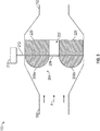
FIG. 3 is cut-away side view of an ozone converter having an internal bypass in the open position according to one embodiment of the present invention; -
FIG. 4 is an end view taken in the airflow direction through of the ozone converter of the flaps and the core shown inFIG. 3 ; -
FIG. 5 is cut-away side view of an ozone converter having an internal bypass in the closed position according to one embodiment of the present invention. -
FIG. 6 is cut-away side view of an ozone converter having an internal bypass according to another embodiment of the present invention; -
FIG. 7a is an end view taken in the airflow direction through the ozone converter shown inFIG. 6 when in the open position; and -
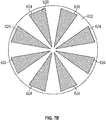
FIG. 7b is an end view taken in the airflow direction through the ozone converter shown inFIG. 6 when in the closed position. -
FIG. 1 illustrates asystem 100 in which embodiments of the present invention may be implemented. Thesystem 100 can be part of an aircraft or any other type of apparatus that can cause thesystem 100 to be moved in a forward direction. For clarity, the following description will assume that thesystem 100 is part of an aircraft but it is not so limited. - The
system 100 illustrated inFIG. 1 includes an environmental control system (ECS) 102. The ECS 102 receivesinput air 104 and providesoutput air 120 to alocation 112 within an apparatus. For example, thelocation 112 could be the flight deck or passenger compartment of an aircraft. It shall be understood that theECS 102 shown inFIG. 1 is extremely simplified and could include many other or different elements. - As illustrated, the ECS 102 includes an air
parameter adjusting unit 106. The airparameter adjusting unit 106, generally, converts the pressure and/or temperature of theinput air 104 to a desired level. In one embodiment, theinput air 104 is bleed air from a compressor section of an engine. In another embodiment, theinput air 104 is ram air received directly from the atmosphere. Regardless of the source of theinput air 104, the airparameter adjusting unit 106 may include aparameter adjustment device 108 that can be operated to adjust the temperature/pressure of theinput air 104. Theparameter adjustment device 108 can be a valve, a turbine, a compressor or device that includes both. In one embodiment, theparameter adjustment device 108 is an electric compressor that compresses ram air. - If the
input air 104 is received while the aircraft is at high altitude, there may a requirement (e.g., contractual or regulatory) that ozone be removed from theinput air 104 before being provided tolocation 112 asoutput air 120. To that end, the ECS 102 also includes anozone converter 110 coupled between the airparameter adjusting unit 106 and thelocation 112. The exact location of theozone converter 110 can be varied from that shown inFIG. 1 in different embodiments of the present invention. - As discussed above, in some cases it may be desirable to bypass the
ozone converter 110 when the ECS 102 receivesinput air 104 from a low altitude source. To accomplish this, one prior art approach was to includebypass line 116 and diverter 114 that caused theinput air 104 to be bypassed around theozone converter 110. InFIG. 1 ,bypass line 116 anddiverter 114 are shown in dashed line to indicate that they are not required (or even desired) components of theECS 102 according to one embodiment. - Embodiments of the present invention are directed to an
ozone converter 110 that can be used in thesystem 100. According to one embodiment, theozone converter 110 includes an internal bypass that allows air to bypass portions of the ozone converter's core without requiring a separate external bypass (e.g., without requiring either diverter 114 or bypass line 116). Such an embodiment, as discussed below includes, one or more actuating panels (or vanes) that can either lie flat against the face of the ozone converter core or be actuated to be parallel to the flow, thereby exposing more of the face of the ozone converter core to the flow. An additional center bypass can be contained on the same shaft allowing for center core bypass when the panels are closed, and then actuating to block the bypass when the panels are open. - In another embodiment, a rotating panel that is placed in front of the ozone convertor core covering or uncovering portions of the ozone convertor core based on an actuator position. In the "open" position a flow is allowed to flow through large bypass sections reducing pressure drop and also serving to isolate sections from contaminants. In the "closed" position which would be used at higher altitudes, the solid portions of the panel cover the bypass slots and allow the air flow through sections of the ozone convertor core.
- Of course, the inclusion of
diverter 114 orbypass line 116 intoECS 102 does not change the fact that any system that includes anozone converter 110 as disclosed herein is within the scope of the present invention. In some cases, theozone converter 110 can save space inECS 102 becausediverter 114 andbypass line 116 are not required. Removal of such elements may provide a space saving that exceeds any increase in size of theozone converter 110 due to the provision of an internal bypass within theozone converter 110 as disclosed herein. - In prior art applications, the ozone converter included a housing formed of a metal such as titanium. The housing is typically formed of two portions that are welded together after the core is inserted. This is not required, however.
-
FIG. 2 shows a perspective view of an example of anozone converter 110 according to embodiment. Theozone converter 110 includes aninlet 150 into which inlet air A enters theozone converter 110 and anoutlet 152 through which outlet air B exits theozone converter 110. Some or all of the ozone contained in inlet air A is removed in theozone converter 110 such that the outlet air B has less ozone in it that the inlet air A. To this end, theozone converter 110 includes a core 162 (FIG. 3 ) that removes some or all of the ozone from the inlet air A to produce outlet air B. - Enclosed within the outer shell is a core. Two different cores will be discussed herein. Each of the cores can be formed of any type of material that causes or otherwise aids in the conversion of ozone into oxygen. For instance, in one embodiment, the core is formed at least partially of palladium.
-
FIG. 3 is cross-section of an example ozone converter taken along its core. While labelled asconverter 110 it shall be understood that the converter is not limited in shape, size or dimension to that shown above and need only include aninlet 150, anoutlet 152 and an outer housing. - The
core 220 is shown as being circular and having apassageway 202 formed through it. Thepassageway 202 may be referred to as acentral passageway 202 herein. Theozone converter 110 includes anactuator 210 that drives an ozone control assembly. Theozone control assembly 204, in operation, controls a flow of air (A) through thecore 220. The control may be partial or complete. For example, in one embodiment, theozone control assembly 204 includes acontrol rod 212 having at least a centralpassageway access cover 206 and one or morecore cover flaps central passageway 202 without passing through thecore 220. Some air may pass through the core as well. However, a portion of the core is not allowed to have air pass through it as it is covered bycore cover flaps -
FIG. 4 shows a view of the core 220 in the direction of the airflow A fromFIG. 3 . InFIG. 4 , theassembly 204 ofFIG. 3 is in the ground mode that allows air to pass through thecentral opening 206 as well as portions of the core that are not covered by theflaps 208, 208b. Such areas in thecore 220 are denoted byreference numeral 402 inFIG. 4 . - Rotation of the
control rod 212 ofFIG. 3 will cause the centralpassageway access cover 206 and theflaps FIG. 5 . In this state, and as indicated by the absence of arrow C inFIG. 5 , air is prevented from passing through thecentral passageway 202 by centralpassageway access cover 206. Further, theflaps rod 212. In this manner, all air A is forced to pass through thecore 220. Therod 212 rotates about axis that is perpendicular to the direction of the flow of airflow A. - In another embodiment, rather than having rotation of an airflow assembly about an axis that is perpendicular to the flow of air, the core and the blocking elements are arranged such that blocking elements can move in front of or away from openings of the core as they are rotated about an axis that is perpendicular to the air flow direction.
-
FIG. 6 shows an example of an embodiment that includes a rotatable ozonecore blocking element 602. Theelement 602 can be circular in one embodiment and includes one or more holes formed in it to allow air to pass through it. Depending on the position of theelement 602, the air will either pass through the core or through holes in thecore 620. Thecore 620 can be formed of any material disclosed herein or that is effective in converting ozone into oxygen. Theelement 602 rotates in a circular manner about an axis X of theconverter 110. Axis X extends in the same or the same general direction that air flows through the converter 110 (e.g., direction A). The rotation may be controlled byactuator 610 which causes theelement 602 to rotate in either direction D or its opposite direction. -
FIGs. 7a and7b show an example of a blockingelement 602 in open (e.g., ground or low flight altitude) and closed (e.g., in flight) positions. respectively, relative to theconverter core 620. As best seen inFIG. 7a thecore 620 is arranged behind (e.g., downstream) of the blockingelement 602. Thecore 620 is illustrated as being formed as a matrix but that is not required. Thecore 620 includes one ormore holes 720 formed therein. As illustrated, thecore 620 includes eightholes 720 formed therein. When on the ground, air passes through theholes 720 as theelement 602 is arranged to allow for such passes (e.g., it does not cover the holes 720). The blockingelement 602 also includesholes 624 that expose theholes 720 in thecore 620 to incoming air (e.g., air A inFIG. 6 ). - As described above, the blocking
element 602 can be rotated such that it covers theholes 720 in thecore 620. This is illustrated inFIG. 7b . In particular, theholes 624 in the blockingelement 602 are not arranged over theholes 720 in thecore 620. In this manner all or most of the air that passes through ozone converter must pass through thecore 620. inFIG. 7a , some or most of the air is allowed to bypass thecore 620 and pass through holes 720. This may lower pressure when on the ground, increase core life and/or prevent fouling. - While the invention has been described in detail in connection with only a limited number of embodiments, it should be readily understood that the invention is not limited to such disclosed embodiments. Rather, the invention can be modified to incorporate any number of variations, alterations, substitutions or equivalent arrangements not heretofore described, but which are commensurate with the scope of the invention as defined by the claims. Additionally, while various embodiments of the invention have been described, it is to be understood that aspects of the invention may include only some of the described embodiments. Accordingly, the invention is not to be seen as limited by the foregoing description, but is only limited by the scope of the appended claims.
Claims (13)
- An ozone converter comprising:an outer housing having an inlet (150) and an outlet (152);a core (162) disposed within the outer housing, the core including a central passageway (202) formed therein and passing through the core; andan ozone control assembly (204) that allows air to pass through the central passageway in a closed mode and prevents flow through the central passageway in an open mode, the assembly including cover flaps (208a, 208b) that cover a portion of the core in the closed mode and that do not cover the core in the open mode.
- The ozone converter of claim 1, further comprising:an actuator (210) that causes the flaps to move when the converter is changed from the closed mode to the open mode or from the open mode to the closed mode.
- The ozone converter of claim 2, wherein the ozone converter is in an aircraft and is in the closed mode when the aircraft is on the ground.
- The ozone converter of claim 2, wherein the ozone control assembly includes:a rod (212) that is controlled by the actuator; anda central passageway access cover (206) connected to the rod;wherein the flaps (208) are connected to the rod.
- The ozone converter of claim 4, wherein the flaps are arranged perpendicular to the central passageway access cover.
- The ozone converter of claim 4, wherein the central passageway access cover prevents flow through the central passageway in the open mode and allows flow through the central passageway in the closed mode.
- The ozone converter of claim 4, wherein the actuator (210) causes the rod (212) rotate to change the converter from the closed mode to the open mode or from the open mode to the closed mode.
- An ozone converter comprising:an outer housing having an inlet (150) and an outlet (152);a core (162) disposed within the outer housing, the core including one or more passageways formed therein and passing through the core; andan ozone control assembly (204) that allows air to pass through the passageways in a closed mode and prevents flow through the passageways in an open mode, the assembly including a rotatable blocking element (602) that covers the passageways in the closed mode and that does not cover the passageways in the open mode.
- The ozone converter of claim 8, further comprising:an actuator (610) that causes the blocking element to rotate about a central axis that is parallel to a longitudinal access of the converter.
- The ozone converter of claim 9, wherein the ozone converter is in an aircraft and is in the open mode when the aircraft is on the ground.
- The ozone converter of claim 8, wherein the rotatable cover element is disposed upstream of the core.
- The ozone converter of claim 8, wherein rotatable blocking element includes holes (624) that are aligned with the one or more passageways in the open mode.
- The ozone converter of claim 4, wherein the actuator causes the rotatable blocking element to change the converter from the closed mode to the open mode or from the open mode to the closed mode by rotating the rotatable blocking element.
Applications Claiming Priority (1)
| Application Number | Priority Date | Filing Date | Title |
|---|---|---|---|
| US15/340,662 US10766623B2 (en) | 2016-11-01 | 2016-11-01 | Ozone converter bypass |
Publications (2)
| Publication Number | Publication Date |
|---|---|
| EP3315189A1 true EP3315189A1 (en) | 2018-05-02 |
| EP3315189B1 EP3315189B1 (en) | 2020-04-22 |
Family
ID=60191272
Family Applications (1)
| Application Number | Title | Priority Date | Filing Date |
|---|---|---|---|
| EP17199206.8A Active EP3315189B1 (en) | 2016-11-01 | 2017-10-30 | Ozone converter bypass |
Country Status (2)
| Country | Link |
|---|---|
| US (1) | US10766623B2 (en) |
| EP (1) | EP3315189B1 (en) |
Families Citing this family (1)
| Publication number | Priority date | Publication date | Assignee | Title |
|---|---|---|---|---|
| FR3165191A1 (en) * | 2024-07-30 | 2026-02-06 | Liebherr-Aerospace Toulouse Sas | OZONE AND/OR VOLATILE ORGANIC COMPOUND CONVERTER INCLUDING A CONICAL FLAP CONTROL VALVE, AIR CONDITIONING SYSTEM AND VEHICLE |
Citations (3)
| Publication number | Priority date | Publication date | Assignee | Title |
|---|---|---|---|---|
| WO1994003265A1 (en) * | 1992-08-07 | 1994-02-17 | Allied-Signal Inc. | Catalytic ozone converter |
| US20130094999A1 (en) * | 2011-10-17 | 2013-04-18 | Hamilton Sundstrand Corporation | Ozone converter with internal bypass |
| CN204447752U (en) * | 2014-12-10 | 2015-07-08 | 中国航空工业集团公司金城南京机电液压工程研究中心 | A kind of aircraft air condition bleed air system deozonize device |
Family Cites Families (6)
| Publication number | Priority date | Publication date | Assignee | Title |
|---|---|---|---|---|
| US2267738A (en) * | 1940-02-17 | 1941-12-30 | Kaufman Hiram Joseph | Apparatus for conditioning air with ice |
| US3401624A (en) * | 1966-08-11 | 1968-09-17 | Aliied Thermal Corp | Air exhauster with damper means |
| WO2002019620A2 (en) | 2000-08-28 | 2002-03-07 | Nice Systems Ltd. | Digital recording of ip based distributed switching platform |
| JP5003976B2 (en) | 2008-01-31 | 2012-08-22 | 株式会社明電舎 | Ozonizer and process system |
| JP5386186B2 (en) | 2009-01-30 | 2014-01-15 | 積水化成品工業株式会社 | Manufacturing method of resin foam sheet |
| US9133028B2 (en) | 2013-04-15 | 2015-09-15 | Hamilton Sundstrand Corporation | Ozone converter with replaceable core |
-
2016
- 2016-11-01 US US15/340,662 patent/US10766623B2/en active Active
-
2017
- 2017-10-30 EP EP17199206.8A patent/EP3315189B1/en active Active
Patent Citations (3)
| Publication number | Priority date | Publication date | Assignee | Title |
|---|---|---|---|---|
| WO1994003265A1 (en) * | 1992-08-07 | 1994-02-17 | Allied-Signal Inc. | Catalytic ozone converter |
| US20130094999A1 (en) * | 2011-10-17 | 2013-04-18 | Hamilton Sundstrand Corporation | Ozone converter with internal bypass |
| CN204447752U (en) * | 2014-12-10 | 2015-07-08 | 中国航空工业集团公司金城南京机电液压工程研究中心 | A kind of aircraft air condition bleed air system deozonize device |
Also Published As
| Publication number | Publication date |
|---|---|
| US20180118352A1 (en) | 2018-05-03 |
| EP3315189B1 (en) | 2020-04-22 |
| US10766623B2 (en) | 2020-09-08 |
Similar Documents
| Publication | Publication Date | Title |
|---|---|---|
| US8973867B2 (en) | Fresh air inlet for an aircraft | |
| EP2792400B1 (en) | Ozone converter with replaceable core | |
| US10208676B2 (en) | Gas turbine engine dual sealing cylindrical variable bleed valve | |
| JP6261192B2 (en) | ENVIRONMENT CONTROL SYSTEM AND OPERATION METHOD OF THE SYSTEM | |
| RU2363853C2 (en) | Air vent intake with movable lapping device | |
| EP2583743B1 (en) | Ozone converter with internal bypass | |
| US9957060B2 (en) | Deployable inlet scoop for an inboard ram air turbine | |
| US20070113579A1 (en) | Low energy electric air cycle with portal shroud cabin air compressor | |
| EP2987985A1 (en) | Actively controlled cooling air exhaust door on aircraft engine nacelle | |
| WO2008031510A1 (en) | Air supply system of an aircraft and method for mixing two air streams in an air supply system | |
| US10787266B2 (en) | Fan bypass and shutoff check valve | |
| EP3447266A1 (en) | Ducted engine compressed bleed valve architecture | |
| RU2449925C2 (en) | Aircraft cooling and ventilation by incident flow | |
| EP3315189B1 (en) | Ozone converter bypass | |
| EP1282556B1 (en) | In flight entertainment (ife) cabinet cooling system | |
| EP2574553B1 (en) | Aircraft outflow valve | |
| CN114340999B (en) | Nacelle internal structure for a turbomachine | |
| DE2135060A1 (en) | Air conditioning system with positive pressurization | |
| US10239625B2 (en) | Ozone converter with altitude activated actuator | |
| EP3986765B1 (en) | System for cooling technical units in a rail vehicle | |
| EP3921194B1 (en) | Cooling unit for a vehicle, vehicle, and method for operating a cooling unit |
Legal Events
| Date | Code | Title | Description |
|---|---|---|---|
| PUAI | Public reference made under article 153(3) epc to a published international application that has entered the european phase |
Free format text: ORIGINAL CODE: 0009012 |
|
| STAA | Information on the status of an ep patent application or granted ep patent |
Free format text: STATUS: THE APPLICATION HAS BEEN PUBLISHED |
|
| AK | Designated contracting states |
Kind code of ref document: A1 Designated state(s): AL AT BE BG CH CY CZ DE DK EE ES FI FR GB GR HR HU IE IS IT LI LT LU LV MC MK MT NL NO PL PT RO RS SE SI SK SM TR |
|
| AX | Request for extension of the european patent |
Extension state: BA ME |
|
| STAA | Information on the status of an ep patent application or granted ep patent |
Free format text: STATUS: REQUEST FOR EXAMINATION WAS MADE |
|
| 17P | Request for examination filed |
Effective date: 20181102 |
|
| RBV | Designated contracting states (corrected) |
Designated state(s): AL AT BE BG CH CY CZ DE DK EE ES FI FR GB GR HR HU IE IS IT LI LT LU LV MC MK MT NL NO PL PT RO RS SE SI SK SM TR |
|
| GRAP | Despatch of communication of intention to grant a patent |
Free format text: ORIGINAL CODE: EPIDOSNIGR1 |
|
| STAA | Information on the status of an ep patent application or granted ep patent |
Free format text: STATUS: GRANT OF PATENT IS INTENDED |
|
| INTG | Intention to grant announced |
Effective date: 20191120 |
|
| RAP1 | Party data changed (applicant data changed or rights of an application transferred) |
Owner name: HAMILTON SUNDSTRAND CORPORATION |
|
| GRAS | Grant fee paid |
Free format text: ORIGINAL CODE: EPIDOSNIGR3 |
|
| GRAA | (expected) grant |
Free format text: ORIGINAL CODE: 0009210 |
|
| STAA | Information on the status of an ep patent application or granted ep patent |
Free format text: STATUS: THE PATENT HAS BEEN GRANTED |
|
| AK | Designated contracting states |
Kind code of ref document: B1 Designated state(s): AL AT BE BG CH CY CZ DE DK EE ES FI FR GB GR HR HU IE IS IT LI LT LU LV MC MK MT NL NO PL PT RO RS SE SI SK SM TR |
|
| REG | Reference to a national code |
Ref country code: CH Ref legal event code: EP |
|
| REG | Reference to a national code |
Ref country code: DE Ref legal event code: R096 Ref document number: 602017015112 Country of ref document: DE |
|
| REG | Reference to a national code |
Ref country code: IE Ref legal event code: FG4D |
|
| REG | Reference to a national code |
Ref country code: AT Ref legal event code: REF Ref document number: 1259334 Country of ref document: AT Kind code of ref document: T Effective date: 20200515 |
|
| REG | Reference to a national code |
Ref country code: LT Ref legal event code: MG4D |
|
| REG | Reference to a national code |
Ref country code: NL Ref legal event code: MP Effective date: 20200422 |
|
| PG25 | Lapsed in a contracting state [announced via postgrant information from national office to epo] |
Ref country code: IS Free format text: LAPSE BECAUSE OF FAILURE TO SUBMIT A TRANSLATION OF THE DESCRIPTION OR TO PAY THE FEE WITHIN THE PRESCRIBED TIME-LIMIT Effective date: 20200822 Ref country code: NO Free format text: LAPSE BECAUSE OF FAILURE TO SUBMIT A TRANSLATION OF THE DESCRIPTION OR TO PAY THE FEE WITHIN THE PRESCRIBED TIME-LIMIT Effective date: 20200722 Ref country code: GR Free format text: LAPSE BECAUSE OF FAILURE TO SUBMIT A TRANSLATION OF THE DESCRIPTION OR TO PAY THE FEE WITHIN THE PRESCRIBED TIME-LIMIT Effective date: 20200723 Ref country code: PT Free format text: LAPSE BECAUSE OF FAILURE TO SUBMIT A TRANSLATION OF THE DESCRIPTION OR TO PAY THE FEE WITHIN THE PRESCRIBED TIME-LIMIT Effective date: 20200824 Ref country code: NL Free format text: LAPSE BECAUSE OF FAILURE TO SUBMIT A TRANSLATION OF THE DESCRIPTION OR TO PAY THE FEE WITHIN THE PRESCRIBED TIME-LIMIT Effective date: 20200422 Ref country code: LT Free format text: LAPSE BECAUSE OF FAILURE TO SUBMIT A TRANSLATION OF THE DESCRIPTION OR TO PAY THE FEE WITHIN THE PRESCRIBED TIME-LIMIT Effective date: 20200422 Ref country code: SE Free format text: LAPSE BECAUSE OF FAILURE TO SUBMIT A TRANSLATION OF THE DESCRIPTION OR TO PAY THE FEE WITHIN THE PRESCRIBED TIME-LIMIT Effective date: 20200422 Ref country code: FI Free format text: LAPSE BECAUSE OF FAILURE TO SUBMIT A TRANSLATION OF THE DESCRIPTION OR TO PAY THE FEE WITHIN THE PRESCRIBED TIME-LIMIT Effective date: 20200422 |
|
| REG | Reference to a national code |
Ref country code: AT Ref legal event code: MK05 Ref document number: 1259334 Country of ref document: AT Kind code of ref document: T Effective date: 20200422 |
|
| PG25 | Lapsed in a contracting state [announced via postgrant information from national office to epo] |
Ref country code: HR Free format text: LAPSE BECAUSE OF FAILURE TO SUBMIT A TRANSLATION OF THE DESCRIPTION OR TO PAY THE FEE WITHIN THE PRESCRIBED TIME-LIMIT Effective date: 20200422 Ref country code: LV Free format text: LAPSE BECAUSE OF FAILURE TO SUBMIT A TRANSLATION OF THE DESCRIPTION OR TO PAY THE FEE WITHIN THE PRESCRIBED TIME-LIMIT Effective date: 20200422 Ref country code: BG Free format text: LAPSE BECAUSE OF FAILURE TO SUBMIT A TRANSLATION OF THE DESCRIPTION OR TO PAY THE FEE WITHIN THE PRESCRIBED TIME-LIMIT Effective date: 20200722 Ref country code: RS Free format text: LAPSE BECAUSE OF FAILURE TO SUBMIT A TRANSLATION OF THE DESCRIPTION OR TO PAY THE FEE WITHIN THE PRESCRIBED TIME-LIMIT Effective date: 20200422 |
|
| PG25 | Lapsed in a contracting state [announced via postgrant information from national office to epo] |
Ref country code: AL Free format text: LAPSE BECAUSE OF FAILURE TO SUBMIT A TRANSLATION OF THE DESCRIPTION OR TO PAY THE FEE WITHIN THE PRESCRIBED TIME-LIMIT Effective date: 20200422 |
|
| REG | Reference to a national code |
Ref country code: DE Ref legal event code: R097 Ref document number: 602017015112 Country of ref document: DE |
|
| PG25 | Lapsed in a contracting state [announced via postgrant information from national office to epo] |
Ref country code: AT Free format text: LAPSE BECAUSE OF FAILURE TO SUBMIT A TRANSLATION OF THE DESCRIPTION OR TO PAY THE FEE WITHIN THE PRESCRIBED TIME-LIMIT Effective date: 20200422 Ref country code: ES Free format text: LAPSE BECAUSE OF FAILURE TO SUBMIT A TRANSLATION OF THE DESCRIPTION OR TO PAY THE FEE WITHIN THE PRESCRIBED TIME-LIMIT Effective date: 20200422 Ref country code: IT Free format text: LAPSE BECAUSE OF FAILURE TO SUBMIT A TRANSLATION OF THE DESCRIPTION OR TO PAY THE FEE WITHIN THE PRESCRIBED TIME-LIMIT Effective date: 20200422 Ref country code: CZ Free format text: LAPSE BECAUSE OF FAILURE TO SUBMIT A TRANSLATION OF THE DESCRIPTION OR TO PAY THE FEE WITHIN THE PRESCRIBED TIME-LIMIT Effective date: 20200422 Ref country code: RO Free format text: LAPSE BECAUSE OF FAILURE TO SUBMIT A TRANSLATION OF THE DESCRIPTION OR TO PAY THE FEE WITHIN THE PRESCRIBED TIME-LIMIT Effective date: 20200422 Ref country code: EE Free format text: LAPSE BECAUSE OF FAILURE TO SUBMIT A TRANSLATION OF THE DESCRIPTION OR TO PAY THE FEE WITHIN THE PRESCRIBED TIME-LIMIT Effective date: 20200422 Ref country code: SM Free format text: LAPSE BECAUSE OF FAILURE TO SUBMIT A TRANSLATION OF THE DESCRIPTION OR TO PAY THE FEE WITHIN THE PRESCRIBED TIME-LIMIT Effective date: 20200422 Ref country code: DK Free format text: LAPSE BECAUSE OF FAILURE TO SUBMIT A TRANSLATION OF THE DESCRIPTION OR TO PAY THE FEE WITHIN THE PRESCRIBED TIME-LIMIT Effective date: 20200422 |
|
| PG25 | Lapsed in a contracting state [announced via postgrant information from national office to epo] |
Ref country code: SK Free format text: LAPSE BECAUSE OF FAILURE TO SUBMIT A TRANSLATION OF THE DESCRIPTION OR TO PAY THE FEE WITHIN THE PRESCRIBED TIME-LIMIT Effective date: 20200422 Ref country code: PL Free format text: LAPSE BECAUSE OF FAILURE TO SUBMIT A TRANSLATION OF THE DESCRIPTION OR TO PAY THE FEE WITHIN THE PRESCRIBED TIME-LIMIT Effective date: 20200422 |
|
| PLBE | No opposition filed within time limit |
Free format text: ORIGINAL CODE: 0009261 |
|
| STAA | Information on the status of an ep patent application or granted ep patent |
Free format text: STATUS: NO OPPOSITION FILED WITHIN TIME LIMIT |
|
| 26N | No opposition filed |
Effective date: 20210125 |
|
| PG25 | Lapsed in a contracting state [announced via postgrant information from national office to epo] |
Ref country code: SI Free format text: LAPSE BECAUSE OF FAILURE TO SUBMIT A TRANSLATION OF THE DESCRIPTION OR TO PAY THE FEE WITHIN THE PRESCRIBED TIME-LIMIT Effective date: 20200422 |
|
| REG | Reference to a national code |
Ref country code: CH Ref legal event code: PL |
|
| PG25 | Lapsed in a contracting state [announced via postgrant information from national office to epo] |
Ref country code: LU Free format text: LAPSE BECAUSE OF NON-PAYMENT OF DUE FEES Effective date: 20201030 Ref country code: MC Free format text: LAPSE BECAUSE OF FAILURE TO SUBMIT A TRANSLATION OF THE DESCRIPTION OR TO PAY THE FEE WITHIN THE PRESCRIBED TIME-LIMIT Effective date: 20200422 |
|
| REG | Reference to a national code |
Ref country code: BE Ref legal event code: MM Effective date: 20201031 |
|
| PG25 | Lapsed in a contracting state [announced via postgrant information from national office to epo] |
Ref country code: LI Free format text: LAPSE BECAUSE OF NON-PAYMENT OF DUE FEES Effective date: 20201031 Ref country code: CH Free format text: LAPSE BECAUSE OF NON-PAYMENT OF DUE FEES Effective date: 20201031 Ref country code: BE Free format text: LAPSE BECAUSE OF NON-PAYMENT OF DUE FEES Effective date: 20201031 |
|
| PG25 | Lapsed in a contracting state [announced via postgrant information from national office to epo] |
Ref country code: IE Free format text: LAPSE BECAUSE OF NON-PAYMENT OF DUE FEES Effective date: 20201030 |
|
| PG25 | Lapsed in a contracting state [announced via postgrant information from national office to epo] |
Ref country code: TR Free format text: LAPSE BECAUSE OF FAILURE TO SUBMIT A TRANSLATION OF THE DESCRIPTION OR TO PAY THE FEE WITHIN THE PRESCRIBED TIME-LIMIT Effective date: 20200422 Ref country code: MT Free format text: LAPSE BECAUSE OF FAILURE TO SUBMIT A TRANSLATION OF THE DESCRIPTION OR TO PAY THE FEE WITHIN THE PRESCRIBED TIME-LIMIT Effective date: 20200422 Ref country code: CY Free format text: LAPSE BECAUSE OF FAILURE TO SUBMIT A TRANSLATION OF THE DESCRIPTION OR TO PAY THE FEE WITHIN THE PRESCRIBED TIME-LIMIT Effective date: 20200422 |
|
| PG25 | Lapsed in a contracting state [announced via postgrant information from national office to epo] |
Ref country code: MK Free format text: LAPSE BECAUSE OF FAILURE TO SUBMIT A TRANSLATION OF THE DESCRIPTION OR TO PAY THE FEE WITHIN THE PRESCRIBED TIME-LIMIT Effective date: 20200422 |
|
| P01 | Opt-out of the competence of the unified patent court (upc) registered |
Effective date: 20230522 |
|
| PGFP | Annual fee paid to national office [announced via postgrant information from national office to epo] |
Ref country code: GB Payment date: 20250923 Year of fee payment: 9 |
|
| PGFP | Annual fee paid to national office [announced via postgrant information from national office to epo] |
Ref country code: FR Payment date: 20250923 Year of fee payment: 9 |
|
| PGFP | Annual fee paid to national office [announced via postgrant information from national office to epo] |
Ref country code: DE Payment date: 20250923 Year of fee payment: 9 |