EP3315089A1 - Head registration using a personalized gripper - Google Patents
Head registration using a personalized gripper Download PDFInfo
- Publication number
- EP3315089A1 EP3315089A1 EP17197953.7A EP17197953A EP3315089A1 EP 3315089 A1 EP3315089 A1 EP 3315089A1 EP 17197953 A EP17197953 A EP 17197953A EP 3315089 A1 EP3315089 A1 EP 3315089A1
- Authority
- EP
- European Patent Office
- Prior art keywords
- gripper
- personalized
- anatomical image
- head
- specific patient
- Prior art date
- Legal status (The legal status is an assumption and is not a legal conclusion. Google has not performed a legal analysis and makes no representation as to the accuracy of the status listed.)
- Withdrawn
Links
Images


Classifications
-
- A—HUMAN NECESSITIES
- A61—MEDICAL OR VETERINARY SCIENCE; HYGIENE
- A61B—DIAGNOSIS; SURGERY; IDENTIFICATION
- A61B34/00—Computer-aided surgery; Manipulators or robots specially adapted for use in surgery
- A61B34/20—Surgical navigation systems; Devices for tracking or guiding surgical instruments, e.g. for frameless stereotaxis
-
- A—HUMAN NECESSITIES
- A61—MEDICAL OR VETERINARY SCIENCE; HYGIENE
- A61B—DIAGNOSIS; SURGERY; IDENTIFICATION
- A61B90/00—Instruments, implements or accessories specially adapted for surgery or diagnosis and not covered by any of the groups A61B1/00 - A61B50/00, e.g. for luxation treatment or for protecting wound edges
- A61B90/39—Markers, e.g. radio-opaque or breast lesions markers
-
- A—HUMAN NECESSITIES
- A61—MEDICAL OR VETERINARY SCIENCE; HYGIENE
- A61B—DIAGNOSIS; SURGERY; IDENTIFICATION
- A61B17/00—Surgical instruments, devices or methods
- A61B17/24—Surgical instruments, devices or methods for use in the oral cavity, larynx, bronchial passages or nose; Tongue scrapers
-
- A—HUMAN NECESSITIES
- A61—MEDICAL OR VETERINARY SCIENCE; HYGIENE
- A61B—DIAGNOSIS; SURGERY; IDENTIFICATION
- A61B34/00—Computer-aided surgery; Manipulators or robots specially adapted for use in surgery
- A61B34/10—Computer-aided planning, simulation or modelling of surgical operations
-
- A—HUMAN NECESSITIES
- A61—MEDICAL OR VETERINARY SCIENCE; HYGIENE
- A61B—DIAGNOSIS; SURGERY; IDENTIFICATION
- A61B6/00—Apparatus or devices for radiation diagnosis; Apparatus or devices for radiation diagnosis combined with radiation therapy equipment
- A61B6/04—Positioning of patients; Tiltable beds or the like
-
- A—HUMAN NECESSITIES
- A61—MEDICAL OR VETERINARY SCIENCE; HYGIENE
- A61B—DIAGNOSIS; SURGERY; IDENTIFICATION
- A61B90/00—Instruments, implements or accessories specially adapted for surgery or diagnosis and not covered by any of the groups A61B1/00 - A61B50/00, e.g. for luxation treatment or for protecting wound edges
- A61B90/36—Image-producing devices or illumination devices not otherwise provided for
- A61B90/37—Surgical systems with images on a monitor during operation
-
- B—PERFORMING OPERATIONS; TRANSPORTING
- B33—ADDITIVE MANUFACTURING TECHNOLOGY
- B33Y—ADDITIVE MANUFACTURING, i.e. MANUFACTURING OF THREE-DIMENSIONAL [3D] OBJECTS BY ADDITIVE DEPOSITION, ADDITIVE AGGLOMERATION OR ADDITIVE LAYERING, e.g. BY 3D PRINTING, STEREOLITHOGRAPHY OR SELECTIVE LASER SINTERING
- B33Y80/00—Products made by additive manufacturing
-
- A—HUMAN NECESSITIES
- A61—MEDICAL OR VETERINARY SCIENCE; HYGIENE
- A61B—DIAGNOSIS; SURGERY; IDENTIFICATION
- A61B17/00—Surgical instruments, devices or methods
- A61B2017/00526—Methods of manufacturing
-
- A—HUMAN NECESSITIES
- A61—MEDICAL OR VETERINARY SCIENCE; HYGIENE
- A61B—DIAGNOSIS; SURGERY; IDENTIFICATION
- A61B34/00—Computer-aided surgery; Manipulators or robots specially adapted for use in surgery
- A61B34/10—Computer-aided planning, simulation or modelling of surgical operations
- A61B2034/101—Computer-aided simulation of surgical operations
- A61B2034/102—Modelling of surgical devices, implants or prosthesis
-
- A—HUMAN NECESSITIES
- A61—MEDICAL OR VETERINARY SCIENCE; HYGIENE
- A61B—DIAGNOSIS; SURGERY; IDENTIFICATION
- A61B34/00—Computer-aided surgery; Manipulators or robots specially adapted for use in surgery
- A61B34/10—Computer-aided planning, simulation or modelling of surgical operations
- A61B2034/108—Computer aided selection or customisation of medical implants or cutting guides
-
- A—HUMAN NECESSITIES
- A61—MEDICAL OR VETERINARY SCIENCE; HYGIENE
- A61B—DIAGNOSIS; SURGERY; IDENTIFICATION
- A61B34/00—Computer-aided surgery; Manipulators or robots specially adapted for use in surgery
- A61B34/20—Surgical navigation systems; Devices for tracking or guiding surgical instruments, e.g. for frameless stereotaxis
- A61B2034/2046—Tracking techniques
- A61B2034/2051—Electromagnetic tracking systems
-
- A—HUMAN NECESSITIES
- A61—MEDICAL OR VETERINARY SCIENCE; HYGIENE
- A61B—DIAGNOSIS; SURGERY; IDENTIFICATION
- A61B34/00—Computer-aided surgery; Manipulators or robots specially adapted for use in surgery
- A61B34/20—Surgical navigation systems; Devices for tracking or guiding surgical instruments, e.g. for frameless stereotaxis
- A61B2034/2046—Tracking techniques
- A61B2034/2055—Optical tracking systems
-
- A—HUMAN NECESSITIES
- A61—MEDICAL OR VETERINARY SCIENCE; HYGIENE
- A61B—DIAGNOSIS; SURGERY; IDENTIFICATION
- A61B34/00—Computer-aided surgery; Manipulators or robots specially adapted for use in surgery
- A61B34/20—Surgical navigation systems; Devices for tracking or guiding surgical instruments, e.g. for frameless stereotaxis
- A61B2034/2046—Tracking techniques
- A61B2034/2065—Tracking using image or pattern recognition
-
- A—HUMAN NECESSITIES
- A61—MEDICAL OR VETERINARY SCIENCE; HYGIENE
- A61B—DIAGNOSIS; SURGERY; IDENTIFICATION
- A61B90/00—Instruments, implements or accessories specially adapted for surgery or diagnosis and not covered by any of the groups A61B1/00 - A61B50/00, e.g. for luxation treatment or for protecting wound edges
- A61B90/36—Image-producing devices or illumination devices not otherwise provided for
- A61B90/37—Surgical systems with images on a monitor during operation
- A61B2090/374—NMR or MRI
-
- A—HUMAN NECESSITIES
- A61—MEDICAL OR VETERINARY SCIENCE; HYGIENE
- A61B—DIAGNOSIS; SURGERY; IDENTIFICATION
- A61B90/00—Instruments, implements or accessories specially adapted for surgery or diagnosis and not covered by any of the groups A61B1/00 - A61B50/00, e.g. for luxation treatment or for protecting wound edges
- A61B90/36—Image-producing devices or illumination devices not otherwise provided for
- A61B90/37—Surgical systems with images on a monitor during operation
- A61B2090/376—Surgical systems with images on a monitor during operation using X-rays, e.g. fluoroscopy
- A61B2090/3762—Surgical systems with images on a monitor during operation using X-rays, e.g. fluoroscopy using computed tomography systems [CT]
-
- A—HUMAN NECESSITIES
- A61—MEDICAL OR VETERINARY SCIENCE; HYGIENE
- A61B—DIAGNOSIS; SURGERY; IDENTIFICATION
- A61B90/00—Instruments, implements or accessories specially adapted for surgery or diagnosis and not covered by any of the groups A61B1/00 - A61B50/00, e.g. for luxation treatment or for protecting wound edges
- A61B90/36—Image-producing devices or illumination devices not otherwise provided for
- A61B90/37—Surgical systems with images on a monitor during operation
- A61B2090/376—Surgical systems with images on a monitor during operation using X-rays, e.g. fluoroscopy
- A61B2090/3762—Surgical systems with images on a monitor during operation using X-rays, e.g. fluoroscopy using computed tomography systems [CT]
- A61B2090/3764—Surgical systems with images on a monitor during operation using X-rays, e.g. fluoroscopy using computed tomography systems [CT] with a rotating C-arm having a cone beam emitting source
-
- A—HUMAN NECESSITIES
- A61—MEDICAL OR VETERINARY SCIENCE; HYGIENE
- A61B—DIAGNOSIS; SURGERY; IDENTIFICATION
- A61B90/00—Instruments, implements or accessories specially adapted for surgery or diagnosis and not covered by any of the groups A61B1/00 - A61B50/00, e.g. for luxation treatment or for protecting wound edges
- A61B90/39—Markers, e.g. radio-opaque or breast lesions markers
- A61B2090/3904—Markers, e.g. radio-opaque or breast lesions markers specially adapted for marking specified tissue
-
- A—HUMAN NECESSITIES
- A61—MEDICAL OR VETERINARY SCIENCE; HYGIENE
- A61B—DIAGNOSIS; SURGERY; IDENTIFICATION
- A61B90/00—Instruments, implements or accessories specially adapted for surgery or diagnosis and not covered by any of the groups A61B1/00 - A61B50/00, e.g. for luxation treatment or for protecting wound edges
- A61B90/39—Markers, e.g. radio-opaque or breast lesions markers
- A61B2090/3954—Markers, e.g. radio-opaque or breast lesions markers magnetic, e.g. NMR or MRI
-
- A—HUMAN NECESSITIES
- A61—MEDICAL OR VETERINARY SCIENCE; HYGIENE
- A61B—DIAGNOSIS; SURGERY; IDENTIFICATION
- A61B90/00—Instruments, implements or accessories specially adapted for surgery or diagnosis and not covered by any of the groups A61B1/00 - A61B50/00, e.g. for luxation treatment or for protecting wound edges
- A61B90/39—Markers, e.g. radio-opaque or breast lesions markers
- A61B2090/3983—Reference marker arrangements for use with image guided surgery
-
- A—HUMAN NECESSITIES
- A61—MEDICAL OR VETERINARY SCIENCE; HYGIENE
- A61B—DIAGNOSIS; SURGERY; IDENTIFICATION
- A61B90/00—Instruments, implements or accessories specially adapted for surgery or diagnosis and not covered by any of the groups A61B1/00 - A61B50/00, e.g. for luxation treatment or for protecting wound edges
- A61B90/39—Markers, e.g. radio-opaque or breast lesions markers
- A61B2090/3991—Markers, e.g. radio-opaque or breast lesions markers having specific anchoring means to fixate the marker to the tissue, e.g. hooks
Definitions
- the present invention relates generally to invasive medical devices, and particularly to methods and systems for registration of an anatomical image with a position-tracking system.
- Registration of an anatomical image with a position-tracking system may be carried out in various medical applications.
- U.S. Patent Application Publication 2014/0037174 whose disclosure is incorporated herein by reference, describes a system that adaptively compensates for subject motion in real-time in an imaging system.
- An object orientation marker preferably a retro-grate reflector (RGR)
- RGR retro-grate reflector
- the marker makes it possible to measure the six degrees of freedom (x, y, and z-translations, and pitch, yaw, and roll), or "pose”, required to track motion of the organ of interest.
- This invention also provides for internal calibration and for co-registration over time of the scanner's and tracking system's reference frames to compensate for drift and other inaccuracies that may arise over time.
- U.S. Patent 7,014,461 whose disclosure is incorporated herein by reference, describes an apparatus for measuring a surface geometry of hard tissue covered by a layer of soft tissue, including a plurality of elements each having a tip adapted to penetrate said soft tissue and not substantially penetrate said hard tissue; a frame supporting movement of said elements, each along a path, such that a plurality of said tips, when positioned along the paths, define a surface; and at least one position sensor which generates a signal indicative of a tip position of at least one of said elements.
- U.S. Patent 5,636,255 whose disclosure is incorporated herein by reference, describes method and system for correlating accuracy of computer tomography (CT) image resolution.
- CT computer tomography
- Small radio-opaque markers having a diameter less than one slice width of a CT scan are embedded in the object, such as a bony skeletal member, to be measured, the object is then CT scanned so that the radio-opaque markers appear in at two slices of the scan.
- the markers are also physically located by detecting them with a sensor, such as a positioning pointer.
- An embodiment of the present invention that is described herein provides a method including acquiring an anatomical image of at least part of a head of a specific patient.
- the anatomical image captures at least a selected location in the head.
- a personalized gripper which is shaped based on the anatomical image to personally fit an organ of the specific patient at the selected location, and which includes a first position sensor of a position-tracking system, is fitted.
- the anatomical image is registered with a coordinate system of the position-tracking system, by identifying the selected location in the anatomical image and measuring a first position of the first position sensor using the position-tracking system.
- a medical device that includes a second position sensor of the position-tracking system, is navigated in the head of the specific patient by displaying a second position of the medical device in the head on the registered anatomical image.
- the selected location includes at least part of a nose of the specific patient. In another embodiment, the selected location includes at least part of a cranium of the specific patient. In yet another embodiment, fitting the personalized gripper includes coupling the first position sensor to the personalized gripper, and subsequently attaching the personalized gripper to the organ.
- the personalized gripper is provided with the first position sensor embedded therein.
- navigating the medical device includes navigating the medical device into a nasal-sinus of the head.
- navigating the medical device includes navigating the medical device into a neural-system of the head.
- the position-tracking system includes a magnetic position-tracking system, and the first and second position sensors include magnetic position sensors. In other embodiments, the position-tracking system includes an optical position-tracking system, and the first and second position sensors include optical markers.
- a method for producing a gripper including receiving an anatomical image of at least part of a head of a specific patient, wherein the anatomical image captures at least a selected location in the head. Instructions are derived from the anatomical image for producing a personalized gripper that is shaped to personally fit an organ at the selected location. The personalized gripper is produced based on the instructions, and a position sensor is coupled to the personalized gripper.
- an article of manufacture including a personalized gripper body, which is shaped to personally fit an organ at a selected location in a head of a specific patient, based on an anatomical image of at least part of the head of the specific patient, and a position sensor coupled to the personalized gripper body.
- Position tracking systems are typically used for navigating catheters, such as suction catheters and guidewires, in image-guided procedures such as sinuplasty.
- a position sensor tracked by the system can be displayed at the correct position over the image.
- a physician may then navigate a medical device having a position sensor thereon using one or more field-generators attached to a frame on a patient's head.
- Such a solution requires an additional session for adjusting the frame to the specific patient and has limited accuracy because the frame can move relative to the patient's head during the procedure.
- FIG. 1 is a schematic pictorial illustration of a sinuplasty procedure using a sinuplasty surgical system 20, in accordance with an embodiment of the present invention.
- System 20 comprises an ear-nose-throat (ENT) tool 28, which a physician 24 inserts into a nose 26 of a patient 22 so as to treat an ENT disease, such as infection in one or more sinuses of patient 22.
- tool 28 may comprise a suction catheter, which is configured to draw infected tissue from at least one of the sinuses.
- tool 28 may comprise a guidewire, which is configured to guide any suitable medical device into the sinuses of patient 22.
- Tool 28 further comprises a proximal end 30, configured to control a distal end 38 of the tool.
- system 20 comprises an optical position tracking system (not shown), which is configured to track the position of one or more position sensors, such as optical markers, in the head of patient 22.
- the optical position tracking system comprises one or more optical markers mounted on ENT tool 28, as well as on a personalized gripper shown in Fig. 2 below.
- the optical position tracking system further comprises one or cameras, which are configured to capture one or more images capturing the optical markers on tool 28 and on the gripper.
- Processor 34 is configured to map the position of each sensor so as to estimate the position and orientation of the distal tip (shown in Fig. 2 below) of tool 28 in the coordinate system of the optical position tracking system.
- Console 33 comprises a driver circuit (not shown), which is configured to drive field-generators 44 with suitable signals so as to generate magnetic fields in a predefined working volume around head 41.
- Processor 34 may be programmed in software to carry out the functions that are used by the system, and to store data in a memory (not shown) to be processed or otherwise used by the software.
- the software may be downloaded to the processor in electronic form, over a network, for example, or it may be provided on non-transitory tangible media, such as optical, magnetic or electronic memory media.
- some or all of the functions of processor 34 may be carried out by dedicated or programmable digital hardware components.
- Fig. 2 is a schematic, pictorial illustration of elements of sinuplasty surgical system 20, in accordance with an embodiment of the present invention.
- physician 24 may acquire one or more anatomical images of head 41, using any suitable imaging modality, such as computerized tomography (CT), cone beam computed tomography (CBCT), or magnetic resonance imaging (MRI).
- CT computerized tomography
- CBCT cone beam computed tomography
- MRI magnetic resonance imaging
- the image may be used for planning the procedure beforehand, as well as for navigating ENT tool 28 into a nasal sinus 48 during the procedure.
- gripper 50 may be produced using any suitable technique, such as techniques for producing molds for dental prostheses.
- a set of grippers may be pre-produced for a specific organ (e.g., front teeth), using printer 21 or any other suitable production technique.
- Each gripper of the set may be shaped to fit a different group of patients, for example each group having similar size and shape of the front teeth, so that the set may cover a wide variety of groups of patients.
- processor 34 may use the anatomical image to derive the shape of the front teeth of a specific patient, and guide physician 24 to select from the set the most suitable gripper for the specific patient.
- a gripper that is selected for a particular patient from a set of predefined grippers is also regarded herein as a personalized gripper.
- an inset 45 is a sideview of the upper front jaw of patient 22.
- an internal surface 55 of the gripper 50 is personally shaped to fit the external surface of gums 54 and one or more front teeth 52 of the specific patient.
- physician 24 may couple (e.g., using a dental glue) a magnetic position sensor 60, for example, to an internal wall 51 of gripper 50, and then fit gripper 50 on gum 54 around front teeth 52.
- the term "internal wall” refers to a wall of gripper 50 facing the inner mouth of patient 22.
- physician 24 may couple sensor 60 at any other suitable location on gripper 50.
- sensor 60 may be already embedded in gripper 50 so that physician 24 may only fit the gripper on teeth 52.
- gripper 50 may comprise a personalized-shaped trench that allows fitting an internal surface 55 of gripper 50 to the external surfaces of gums 54 and teeth 52, as shown in inset 45.
- gripper 50 may have any suitable 3D or even two-dimensional (2D) shape that allows fitting sensor 60 stiffly to any suitable organ or tissue in head 41.
- System 20 further comprises a magnetic position sensor 56 attached to the tip of distal end 38, which is inserted into nasal sinus 48 during the sinuplasty procedure as described in detail in Fig. 4 below.
- the position of sensor 56 is typically measured using the magnetic position tracking system, as described in Fig. 1 above.
- gripper 50 may be formed to fit any other suitable organ in head 41, for example, a bite bar for the upper and lower jaws, a nose gripper, or a head clamp.
- shape of the organ in the anatomical image, to which the gripper is to be fitted may be used to derive instructions for producing the personalized gripper.
- the anatomical image should typically include the entire organ in question.
- the anatomical image may comprise at least part of the upper and lower jaws of the specific patient. These jaw parts may be used to derive the instructions for producing a personalized bite bar or a teeth gripper.
- the anatomical image may capture at least part of a cranium of head 41 so as to derive instructions to produce the personalized head clamp that fits the specific part of the cranium of patient 22.
- the anatomical image may capture at least part of nose 26 so as to derive instructions to produce the nose gripper.
- processor 34 analyzes the CT images to identify in the images the shape of teeth 52, which is specific to patient 22. Processor 34 derives, based on the identified shape of teeth 52, one or more instruction files that comprises machine instructions producing gripper 50.
- system 20 may send the instruction files to the 3D printer for producing personalized gripper 50, typically from biocompatible materials.
- an operator e.g., physician 24, or a manufacturing technician couples sensor 60 to gripper 50 as depicted in Fig. 2 above.
- Fig. 4 is a flow chart that schematically illustrates a method for carrying out a sinuplasty procedure using personalized gripper 50, in accordance with an embodiment of the present invention.
- the method begins with acquiring one or more CT images of at least part of head 41 (e.g., using an external CT imager), and providing the CT images to processor 34, at an imaging step 200.
- the CT images capture at least teeth 52, which is selected in advance by physician 22 for fitting gripper 50.
- a gripper fitting step 206 physician 22 fits internal surface 55 of gripper 50 on the external surfaces of gums 54 and teeth 52, as shown in inset 45.
- processor 34 registers the one or more CT images with the coordinate system of the magnetic position tracking system by identifying front teeth 52 in the CT image and measuring the position of sensor 60 (that is coupled to gripper 50 and therefore has a fixed location relative to teeth 52) in the coordinate system of the position tracking system. Note that after the registration, the position of sensor 60 is anchored to teeth 52 in the coordinate system, and therefore, also in the CT images during the procedure, even when moving the head of patient 22.
- processor 34 by continuously tracking the position of sensor 60 relative to sensor 56, processor 34 is configured to dynamically maintain the registration of the CT image with the position tracking system even when patient 22 moves his/her head. Furthermore, processor 34 may continuously display the position of sensors 56 and 60 on the CT image displayed of user display 36, thus, assisting physician 24 to carry out the sinuplasty procedure.
- the disclosed technique may be used in any surgical procedure, such as brain surgery, in a spinal cord, by fitting the personalized gripper to a suitable organ or tissue such as one of the spinal vertebras.
Landscapes
- Health & Medical Sciences (AREA)
- Life Sciences & Earth Sciences (AREA)
- Surgery (AREA)
- Engineering & Computer Science (AREA)
- Nuclear Medicine, Radiotherapy & Molecular Imaging (AREA)
- Medical Informatics (AREA)
- Veterinary Medicine (AREA)
- Heart & Thoracic Surgery (AREA)
- Molecular Biology (AREA)
- Animal Behavior & Ethology (AREA)
- General Health & Medical Sciences (AREA)
- Public Health (AREA)
- Biomedical Technology (AREA)
- Oral & Maxillofacial Surgery (AREA)
- Pathology (AREA)
- Robotics (AREA)
- Radiology & Medical Imaging (AREA)
- Chemical & Material Sciences (AREA)
- Otolaryngology (AREA)
- Materials Engineering (AREA)
- Manufacturing & Machinery (AREA)
- Pulmonology (AREA)
- Dentistry (AREA)
- High Energy & Nuclear Physics (AREA)
- Gynecology & Obstetrics (AREA)
- Optics & Photonics (AREA)
- Biophysics (AREA)
- Physics & Mathematics (AREA)
- Magnetic Resonance Imaging Apparatus (AREA)
- Apparatus For Radiation Diagnosis (AREA)
- Surgical Instruments (AREA)
Abstract
Description
- The present invention relates generally to invasive medical devices, and particularly to methods and systems for registration of an anatomical image with a position-tracking system.
- Registration of an anatomical image with a position-tracking system may be carried out in various medical applications.
- For example,
U.S. Patent Application Publication 2014/0037174 , whose disclosure is incorporated herein by reference, describes a system that adaptively compensates for subject motion in real-time in an imaging system. An object orientation marker, preferably a retro-grate reflector (RGR), is placed on the head or other body organ of interest of a patient during a scan, such as an MRI scan. The marker makes it possible to measure the six degrees of freedom (x, y, and z-translations, and pitch, yaw, and roll), or "pose", required to track motion of the organ of interest. This invention also provides for internal calibration and for co-registration over time of the scanner's and tracking system's reference frames to compensate for drift and other inaccuracies that may arise over time. -
U.S. Patent 7,014,461 , whose disclosure is incorporated herein by reference, describes an apparatus for measuring a surface geometry of hard tissue covered by a layer of soft tissue, including a plurality of elements each having a tip adapted to penetrate said soft tissue and not substantially penetrate said hard tissue; a frame supporting movement of said elements, each along a path, such that a plurality of said tips, when positioned along the paths, define a surface; and at least one position sensor which generates a signal indicative of a tip position of at least one of said elements. -
U.S. Patent 5,636,255 , whose disclosure is incorporated herein by reference, describes method and system for correlating accuracy of computer tomography (CT) image resolution. Small radio-opaque markers having a diameter less than one slice width of a CT scan are embedded in the object, such as a bony skeletal member, to be measured, the object is then CT scanned so that the radio-opaque markers appear in at two slices of the scan. The markers are also physically located by detecting them with a sensor, such as a positioning pointer. - An embodiment of the present invention that is described herein provides a method including acquiring an anatomical image of at least part of a head of a specific patient. The anatomical image captures at least a selected location in the head. A personalized gripper, which is shaped based on the anatomical image to personally fit an organ of the specific patient at the selected location, and which includes a first position sensor of a position-tracking system, is fitted. The anatomical image is registered with a coordinate system of the position-tracking system, by identifying the selected location in the anatomical image and measuring a first position of the first position sensor using the position-tracking system. A medical device that includes a second position sensor of the position-tracking system, is navigated in the head of the specific patient by displaying a second position of the medical device in the head on the registered anatomical image.
- In some embodiments, acquiring the anatomical image includes acquiring one or more images of a modality selected from a list consisting of computerized tomography (CT), cone beam computed tomography (CBCT), and magnetic resonance imaging (MRI). In other embodiments, the selected location includes one or more teeth of the specific patient. In yet other embodiments, the selected location includes at least part of an upper jaw and at least part of a lower jaw of the specific patient, and fitting the personalized gripper includes fitting a bite bar, which is shaped to personally fit the at least part of the upper jaw and the at least part of the lower jaw of the specific patient.
- In an embodiment, the selected location includes at least part of a nose of the specific patient. In another embodiment, the selected location includes at least part of a cranium of the specific patient. In yet another embodiment, fitting the personalized gripper includes coupling the first position sensor to the personalized gripper, and subsequently attaching the personalized gripper to the organ.
- In some embodiments, the personalized gripper is provided with the first position sensor embedded therein. In other embodiments, navigating the medical device includes navigating the medical device into a nasal-sinus of the head. In yet other embodiments, navigating the medical device includes navigating the medical device into a neural-system of the head.
- In an embodiment, the medical device includes a suction catheter. In another embodiment, the medical device includes a guidewire.
- In some embodiments, the position-tracking system includes a magnetic position-tracking system, and the first and second position sensors include magnetic position sensors. In other embodiments, the position-tracking system includes an optical position-tracking system, and the first and second position sensors include optical markers.
- There is additionally provided, in accordance with an embodiment of the present invention, a method for producing a gripper, including receiving an anatomical image of at least part of a head of a specific patient, wherein the anatomical image captures at least a selected location in the head. Instructions are derived from the anatomical image for producing a personalized gripper that is shaped to personally fit an organ at the selected location. The personalized gripper is produced based on the instructions, and a position sensor is coupled to the personalized gripper.
- There is further provided, in accordance with an embodiment of the present invention, an article of manufacture including a personalized gripper body, which is shaped to personally fit an organ at a selected location in a head of a specific patient, based on an anatomical image of at least part of the head of the specific patient, and a position sensor coupled to the personalized gripper body.
- The present invention will be more fully understood from the following detailed description of the embodiments thereof, taken together with the drawings in which:
-
-
FIG. 1 is a schematic, pictorial illustration of a sinuplasty surgical system, in accordance with an embodiment of the present invention; -
Fig. 2 is a schematic, pictorial illustration of elements of a sinuplasty surgical system, in accordance with an embodiment of the present invention; -
Fig. 3 is a flow chart that schematically illustrates a method for producing a personalized gripper, in accordance with an embodiment of the present invention; and -
Fig. 4 is a flow chart that schematically illustrates a method for carrying out a sinuplasty procedure using a personalized gripper, in accordance with an embodiment of the present invention. - Position tracking systems are typically used for navigating catheters, such as suction catheters and guidewires, in image-guided procedures such as sinuplasty. In principle, it is possible to acquire an anatomical image that includes an organ to be treated prior to the medical procedure, and register the image to a coordinate system of the position tracking system. When the image is registered, a position sensor tracked by the system can be displayed at the correct position over the image. A physician may then navigate a medical device having a position sensor thereon using one or more field-generators attached to a frame on a patient's head. Such a solution, however, requires an additional session for adjusting the frame to the specific patient and has limited accuracy because the frame can move relative to the patient's head during the procedure.
- Embodiments of the present invention that are described hereinbelow provide improved techniques for registering an anatomical image with the coordinate system of a position-tracking system, using a personalized gripper that is manufactured based on the anatomical image and comprises a position sensor. The shape of the personalized gripper is designed to fit a selected non-movable organ in the head of the specific patient (e.g., a tooth) and therefore has a fixed known location relative to the head during the medical procedure.
- Before applying the procedure, an anatomical image of the patient's head is acquired for planning the procedure and for navigating the medical device during the procedure. The embodiments described herein refer mainly to suitable medical device, such as ear-nose-throat (ENT) surgical tools, probes, suction tools, navigation guidewires, shavers, and drillers, however, the disclosed techniques are applicable for any medical instrument used for ENT applications. In some embodiments, the image contains the location in which the gripper is fitted, such as one or more front teeth of the patient. In an embodiment, the shape of the teeth in the image is used to derive instructions for producing a biocompatible personalized gripper that fits the specific patient, using a three-dimensional (3D) printer or any alternative manufacturing technique such as having a bank of grippers for variety of teeth shape.
- In an embodiment, the gripper comprises a first position sensor coupled thereto, and the physician fits the gripper on the front teeth. In an alternative embodiment, the physician couples the first position sensor to the gripper and fits the gripper on the front teeth.
- In some embodiments, the front teeth to which the gripper was fitted are identified in the image, and the position of the first sensor (in the gripper) is measured using the tracking system so as to register the image with the coordinate system of the position tracking system. Based on the registration, the position of a position sensor measured using the position tracking system can be displayed to the physician, overlaid on the anatomical image. With this kind of display, when the physician inserts an ENT tool having a second position sensor, e.g., at its distal end, into the patient's nose, the distal end is displayed correctly relative to the image. The physician may navigate the ENT tool on the registered anatomical image to a selected location in the patient's head, such as a nasal sinus, so as to carry out the sinuplasty procedure. In an embodiment, the first sensor in the gripper may serve as a reference position so that the second sensor is displayed accurately over the image even when the patient moves his/her head during the procedure.
- The disclosed techniques enable automatic registration of the anatomical image to the position tracking system prior to the sinuplasty procedure, thereby eliminating the need for manual registration by the physician during the sinuplasty procedure. Furthermore, the accurate fixation of the gripper to the teeth reduces the need to repeat the registration, for example, when the patient's head moves.
- The proposed techniques enable the physician to navigate the ENT tool to the nasal sinus accurately without navigation-related delays, thus shortening the sinuplasty procedure. Furthermore, the disclosed techniques may save time, cost and effort because the patient does not have to attend the additional session for adjusting the frame as described above.
-
FIG. 1 is a schematic pictorial illustration of a sinuplasty procedure using a sinuplastysurgical system 20, in accordance with an embodiment of the present invention.System 20 comprises an ear-nose-throat (ENT)tool 28, which aphysician 24 inserts into anose 26 of a patient 22 so as to treat an ENT disease, such as infection in one or more sinuses ofpatient 22. In some embodiments,tool 28 may comprise a suction catheter, which is configured to draw infected tissue from at least one of the sinuses. In other embodiments,tool 28 may comprise a guidewire, which is configured to guide any suitable medical device into the sinuses ofpatient 22.Tool 28 further comprises aproximal end 30, configured to control adistal end 38 of the tool. - In an embodiment,
system 20 further comprises a magnetic position tracking system, which is configured to track the position of one or more position sensors in the head ofpatient 22. The magnetic position tracking system comprises magnetic field-generators 44 and one or more position sensors. The position sensors generate position signals in response to the sensed external magnetic fields from the field generators, thereby enabling aprocessor 34 to map the position of each sensor as will be described below. - This method of position sensing is implemented in various medical applications, for example, in the CARTO™ system, produced by Biosense Webster Inc. (Diamond Bar, Calif.) and is described in detail in
U.S. Patents 5, 391, 199 ,6, 690, 963 ,6, 484, 118 ,6, 239, 724 ,6, 618, 612 and6,332,089 , inPCT Patent Publication WO 96/05768 U.S. Patent Application Publications 2002/0065455 A1 ,2003/0120150 A1 and2004/0068178 A1 , whose disclosures are all incorporated herein by reference. -
System 20 further comprises alocation pad 40, which comprises field-generators 44 fixed on aframe 46. In the exemplary configuration shown inFIG. 1 ,pad 40 comprises five field-generators 44 but may comprise any other suitable number ofgenerators 44.Pad 40 further comprises apillow 42 placed under ahead 41 ofpatient 22, such thatgenerators 44 are located at fixed, known positions external to the patient. - In an alternative embodiment,
system 20 comprises an optical position tracking system (not shown), which is configured to track the position of one or more position sensors, such as optical markers, in the head ofpatient 22. In one example embodiment, the optical position tracking system comprises one or more optical markers mounted onENT tool 28, as well as on a personalized gripper shown inFig. 2 below. The optical position tracking system further comprises one or cameras, which are configured to capture one or more images capturing the optical markers ontool 28 and on the gripper.Processor 34 is configured to map the position of each sensor so as to estimate the position and orientation of the distal tip (shown inFig. 2 below) oftool 28 in the coordinate system of the optical position tracking system. -
System 20 further comprises aconsole 33, which comprisesprocessor 34, typically a general-purpose computer, with suitable front end and interface circuits for receiving signals fromtool 28 having a magnetic sensor attached thereon (shown inFig. 2 below), via acable 32, and for controlling other components ofsystem 20 described herein.Processor 34 is further configured to derive one or more instruction files for use by a three-dimensional (3D)printer 21, typically located at a production site, away from the location ofsystem 20. The instruction files are derived from one or more anatomical images ofhead 41, as will be described in detail inFig. 2 below.Console 33 further comprisesinput devices 39 and auser display 36, which is configured to display the data (e.g., images) received fromprocessor 34 or inputs inserted by a user (e.g., physician 24). -
Console 33 comprises a driver circuit (not shown), which is configured to drive field-generators 44 with suitable signals so as to generate magnetic fields in a predefined working volume aroundhead 41. -
Fig. 1 shows only elements related to the disclosed techniques, for the sake of simplicity and clarity.System 20 typically comprises additional modules and elements that are not directly related to the disclosed techniques, and thus, intentionally omitted fromFig. 1 and from the corresponding description. -
Processor 34 may be programmed in software to carry out the functions that are used by the system, and to store data in a memory (not shown) to be processed or otherwise used by the software. The software may be downloaded to the processor in electronic form, over a network, for example, or it may be provided on non-transitory tangible media, such as optical, magnetic or electronic memory media. Alternatively, some or all of the functions ofprocessor 34 may be carried out by dedicated or programmable digital hardware components. -
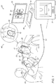
Fig. 2 is a schematic, pictorial illustration of elements of sinuplastysurgical system 20, in accordance with an embodiment of the present invention. In an embodiment, prior to the sinuplasty procedure,physician 24 may acquire one or more anatomical images ofhead 41, using any suitable imaging modality, such as computerized tomography (CT), cone beam computed tomography (CBCT), or magnetic resonance imaging (MRI). The image may be used for planning the procedure beforehand, as well as for navigatingENT tool 28 into anasal sinus 48 during the procedure. - In some embodiments, the anatomical image may also be used for deriving instructions for producing a
personalized gripper 50 that is shaped to fitfront teeth 52 of thespecific patient 22. In the present context and in the claims, the term "personalized gripper" refers to a gripper intended to fit a specific organ of a specific patient. The specific organ that can verify accurate fitting of the sensor (e.g., teeth 52) typically differs in shape from one patient to another so that the personalized gripper fits, for example,teeth 52 ofspecific patient 22, but generally not the teeth of any other patient. In an embodiment,processor 34 may be configured to derive one or more instruction files for producinggripper 50 usingprinter 21. - In alternative embodiments,
gripper 50 may be produced using any suitable technique, such as techniques for producing molds for dental prostheses. In yet alternative embodiments, a set of grippers may be pre-produced for a specific organ (e.g., front teeth), usingprinter 21 or any other suitable production technique. Each gripper of the set may be shaped to fit a different group of patients, for example each group having similar size and shape of the front teeth, so that the set may cover a wide variety of groups of patients. In an embodiment,processor 34 may use the anatomical image to derive the shape of the front teeth of a specific patient, and guidephysician 24 to select from the set the most suitable gripper for the specific patient. A gripper that is selected for a particular patient from a set of predefined grippers is also regarded herein as a personalized gripper. - Reference is now made to an
inset 45, which is a sideview of the upper front jaw ofpatient 22. As explained above and as can be seen in the figure, aninternal surface 55 of thegripper 50 is personally shaped to fit the external surface ofgums 54 and one or morefront teeth 52 of the specific patient. - In an embodiment, prior to the sinuplasty procedure,
physician 24 may couple (e.g., using a dental glue) amagnetic position sensor 60, for example, to aninternal wall 51 ofgripper 50, and then fitgripper 50 ongum 54 aroundfront teeth 52. The term "internal wall" refers to a wall ofgripper 50 facing the inner mouth ofpatient 22. Alternatively,physician 24 may couplesensor 60 at any other suitable location ongripper 50. In an alternative embodiment,sensor 60 may be already embedded ingripper 50 so thatphysician 24 may only fit the gripper onteeth 52. - In some embodiments,
gripper 50 may comprise a personalized-shaped trench that allows fitting aninternal surface 55 ofgripper 50 to the external surfaces ofgums 54 andteeth 52, as shown ininset 45. In alternative embodiments,gripper 50 may have any suitable 3D or even two-dimensional (2D) shape that allowsfitting sensor 60 stiffly to any suitable organ or tissue inhead 41. -
System 20 further comprises amagnetic position sensor 56 attached to the tip ofdistal end 38, which is inserted intonasal sinus 48 during the sinuplasty procedure as described in detail inFig. 4 below. The position ofsensor 56 is typically measured using the magnetic position tracking system, as described inFig. 1 above. - In other embodiments,
gripper 50 may comprise a registration groove (not shown) formed, for example, in anexternal wall 53 ofgripper 50. The registration groove is located at a fixed coordinate offset relative tosensor 60. Before the sinuplasty procedure,physician 24 may insert the distal tip of tool 28 (which comprises position sensor 56) into the registration groove so as to calibrate the position ofsensor 56 in a coordinate system of the magnetic position tracking system. The calibration is carried out by assigning tosensor 56 initial coordinates that are in a known offset relative to the coordinates of the gripper sensor as the groove. In an alternative embodiment,system 20 may comprise an optical-based positioning system for calibrating the position of an optical sensor (instead of sensor 56) when the tip is inserted into the groove. - In alternative embodiments,
gripper 50 may be formed to fit any other suitable organ inhead 41, for example, a bite bar for the upper and lower jaws, a nose gripper, or a head clamp. In an embodiment, the shape of the organ in the anatomical image, to which the gripper is to be fitted, may be used to derive instructions for producing the personalized gripper. The anatomical image should typically include the entire organ in question. In an example embodiment, the anatomical image may comprise at least part of the upper and lower jaws of the specific patient. These jaw parts may be used to derive the instructions for producing a personalized bite bar or a teeth gripper. - In another embodiment, the anatomical image may capture at least part of a cranium of
head 41 so as to derive instructions to produce the personalized head clamp that fits the specific part of the cranium ofpatient 22. In yet another embodiment, the anatomical image may capture at least part ofnose 26 so as to derive instructions to produce the nose gripper. -
Fig. 3 is a flow chart that schematically illustrates a method for producingpersonalized gripper 50, in accordance with an embodiment of the present invention. The method begins withprocessor 34 receiving one or more CT images capturing at least part ofhead 41, at aCT imaging step 100. The CT images in this example capture atleast teeth 52, which are selected byphysician 22 for fittinggripper 50. In the present example, based on the CT images, the method generates instructions for producinggripper 50, which is personalized toteeth 52 ofspecific patient 22. - At an
instruction deriving step 102,processor 34 analyzes the CT images to identify in the images the shape ofteeth 52, which is specific topatient 22.Processor 34 derives, based on the identified shape ofteeth 52, one or more instruction files that comprises machineinstructions producing gripper 50. - At a
gripper formation step 104,system 20 may send the instruction files to the 3D printer for producingpersonalized gripper 50, typically from biocompatible materials. At a positionsensor coupling step 106, an operator (e.g.,physician 24, or a manufacturing technician) couplessensor 60 to gripper 50 as depicted inFig. 2 above. -
Fig. 4 is a flow chart that schematically illustrates a method for carrying out a sinuplasty procedure usingpersonalized gripper 50, in accordance with an embodiment of the present invention. The method begins with acquiring one or more CT images of at least part of head 41 (e.g., using an external CT imager), and providing the CT images toprocessor 34, at animaging step 200. The CT images capture atleast teeth 52, which is selected in advance byphysician 22 for fittinggripper 50. - At an
instruction deriving step 202,processor 34 derives from the CT image, the instruction files for producinggripper 50, as described atinstruction deriving step 102 above. At asensor coupling step 204,physician 22 couples positionsensor 60 topersonalized gripper 50 that was produced atstep 202. In alternative embodiments,gripper 50 already comprisessensor 60 embedded therein at production. - At a gripper
fitting step 206,physician 22 fitsinternal surface 55 ofgripper 50 on the external surfaces ofgums 54 andteeth 52, as shown ininset 45. At aregistration step 208,processor 34 registers the one or more CT images with the coordinate system of the magnetic position tracking system by identifyingfront teeth 52 in the CT image and measuring the position of sensor 60 (that is coupled togripper 50 and therefore has a fixed location relative to teeth 52) in the coordinate system of the position tracking system. Note that after the registration, the position ofsensor 60 is anchored toteeth 52 in the coordinate system, and therefore, also in the CT images during the procedure, even when moving the head ofpatient 22. - At an ENT
tool insertion step 210, physician insertstool 28 intonose 26 ofpatient 22 so as to carry out the sinuplasty procedure.Sensor 56, which is attached at the distal tip oftool 28 allowsphysician 24 to track the position ofdistal end 38 using the magnetic position tracking system. At anavigation step 212,physician 24 navigatesdistal end 38 intonasal sinus 48 usingposition sensor 56 whose measured position is displayed overlaid on the CT image. - In some embodiments, by continuously tracking the position of
sensor 60 relative tosensor 56,processor 34 is configured to dynamically maintain the registration of the CT image with the position tracking system even when patient 22 moves his/her head. Furthermore,processor 34 may continuously display the position ofsensors user display 36, thus, assistingphysician 24 to carry out the sinuplasty procedure. - In other embodiments, the proposed techniques may be used, mutatis mutandis, in various other types of surgical, diagnostic and therapeutic procedures. For example, a neuro-surgeon may use
gripper 50 onteeth 52 for tracking one or more ENT tools in a neural-system ofpatient 22, such as patient's brain or spinal cord. - In alternative embodiments, the disclosed technique may be used in any surgical procedure, such as brain surgery, in a spinal cord, by fitting the personalized gripper to a suitable organ or tissue such as one of the spinal vertebras.
- It will be appreciated that the embodiments described above are cited by way of example, and that the present invention is not limited to what has been particularly shown and described hereinabove. Rather, the scope of the present invention includes both combinations and subcombinations of the various features described hereinabove, as well as variations and modifications thereof which would occur to persons skilled in the art upon reading the foregoing description and which are not disclosed in the prior art. Documents incorporated by reference in the present patent application are to be considered an integral part of the application except that to the extent any terms are defined in these incorporated documents in a manner that conflicts with the definitions made explicitly or implicitly in the present specification, only the definitions in the present specification should be considered.
-
- 1. A method, comprising:
- acquiring an anatomical image of at least part of a head of a specific patient, wherein the anatomical image captures at least a selected location in the head;
- fitting a personalized gripper, which is shaped based on the anatomical image to personally fit an organ of the specific patient at the selected location, and which comprises a first position sensor of a position-tracking system;
- registering the anatomical image with a coordinate system of the position-tracking system, by identifying the selected location in the anatomical image and measuring a first position of the first position sensor using the position-tracking system; and
- navigating in the head of the specific patient a medical device that comprises a second position sensor of the position-tracking system, by displaying a second position of the medical device in the head on the registered anatomical image.
- 2. The method according to aspect 1, wherein acquiring the anatomical image comprises acquiring one or more images using modality selected from a list consisting of computerized tomography (CT), cone beam computed tomography (CBCT), and magnetic resonance imaging (MRI).
- 3. The method according to aspect 1, wherein the selected location comprises one or more teeth of the specific patient.
- 4. The method according to aspect 1, wherein the selected location comprises at least part of an upper jaw and at least part of a lower jaw of the specific patient, and wherein fitting the personalized gripper comprises fitting a bite bar, which is shaped to personally fit the at least part of the upper jaw and the at least part of the lower jaw of the specific patient.
- 5. The method according to aspect 1, wherein the selected location comprises at least part of a nose of the specific patient.
- 6. The method according to aspect 1, wherein the selected location comprises at least part of a cranium of the specific patient.
- 7. The method according to aspect 1, wherein fitting the personalized gripper comprises coupling the first position sensor to the personalized gripper, and subsequently attaching the personalized gripper to the organ.
- 8. The method according to aspect 1, wherein the personalized gripper is provided with the first position sensor embedded therein.
- 9. The method according to aspect 1, wherein navigating the medical device comprises navigating the medical device into a nasal-sinus of the head.
- 10. The method according to aspect 1, wherein navigating the medical device comprises navigating the medical device into a neural-system of the head.
- 11. The method according to aspect 1, wherein the medical device comprises a suction catheter.
- 12. The method according to aspect 1, wherein the medical device comprises a guidewire.
- 13. The method according to aspect 1, wherein the position-tracking system comprises a magnetic position-tracking system, and wherein the first and second position sensors comprise magnetic position sensors.
- 14. The method according to aspect 1, wherein the position-tracking system comprises an optical position-tracking system, and wherein the first and second position sensors comprise optical markers.
Claims (12)
- An article of manufacture, comprising:a personalized gripper body, which is shaped to personally fit an organ at a selected location in a head of a specific patient, based on an anatomical image of at least part of the head of the specific patient; anda position sensor coupled to the personalized gripper body.
- The article of manufacture according to claim 1, wherein the gripper body comprises a groove, which is shaped to fit a distal tip of a catheter.
- The article of manufacture according to claim 1, wherein the organ comprises one or more teeth of the specific patient.
- The article of manufacture according to claim 1, wherein the personalized gripper is made of at least one biocompatible material.
- The article of manufacture according to claim 1, wherein the position sensor is configured to be coupled to the personalized gripper by gluing the position sensor to the personalized gripper.
- A method for producing a gripper, the method comprising:receiving an anatomical image of at least part of a head of a specific patient, wherein the anatomical image captures at least a selected location in the head;deriving from the anatomical image instructions for producing a personalized gripper that is shaped to personally fit an organ at the selected location;producing the personalized gripper based on the instructions; andcoupling a position sensor to the personalized gripper.
- The method according to claim 6, wherein receiving the anatomical image comprises receiving one or more images of a modality selected from a list consisting of computerized tomography (CT), cone beam computed tomography (CBCT), and magnetic resonance imaging (MRI).
- The method according to claim 6, wherein receiving the anatomical image comprises receiving the anatomical image of one or more teeth of the specific patient.
- The method according to claim 8, wherein deriving the instructions comprises estimating, from the anatomical image, the shape of the one or more teeth of the specific patient, and producing instructions for manufacturing the gripper in accordance with the estimated shape.
- The method according to claim 6, wherein producing the personalized gripper comprises printing the personalized gripper by a three-dimensional (3D) printer in accordance with the instructions.
- The method according to claim 10, wherein producing the personalized gripper comprises printing the personalized gripper from at least one biocompatible material.
- The method according to claim 6, wherein receiving the anatomical image comprises receiving an image of at least part of a nose of the specific patient, and wherein producing the personalized gripper comprises producing a nose gripper.
Applications Claiming Priority (1)
| Application Number | Priority Date | Filing Date | Title |
|---|---|---|---|
| US15/334,183 US10631935B2 (en) | 2016-10-25 | 2016-10-25 | Head registration using a personalized gripper |
Publications (1)
| Publication Number | Publication Date |
|---|---|
| EP3315089A1 true EP3315089A1 (en) | 2018-05-02 |
Family
ID=60191123
Family Applications (1)
| Application Number | Title | Priority Date | Filing Date |
|---|---|---|---|
| EP17197953.7A Withdrawn EP3315089A1 (en) | 2016-10-25 | 2017-10-24 | Head registration using a personalized gripper |
Country Status (7)
| Country | Link |
|---|---|
| US (1) | US10631935B2 (en) |
| EP (1) | EP3315089A1 (en) |
| JP (2) | JP2018079309A (en) |
| CN (1) | CN107970074B (en) |
| AU (1) | AU2017245399A1 (en) |
| CA (1) | CA2983489A1 (en) |
| IL (1) | IL254850A0 (en) |
Cited By (1)
| Publication number | Priority date | Publication date | Assignee | Title |
|---|---|---|---|---|
| CN111407406A (en) * | 2020-03-31 | 2020-07-14 | 武汉联影智融医疗科技有限公司 | Head position identification device, intraoperative control system and control method |
Families Citing this family (16)
| Publication number | Priority date | Publication date | Assignee | Title |
|---|---|---|---|---|
| US11389254B2 (en) | 2016-08-18 | 2022-07-19 | Envizion Medical Ltd. | Insertion device positioning guidance system and method |
| IL254009A0 (en) | 2016-08-18 | 2017-09-28 | Nutriseal Lp | Insertion device positioning guidance system and method |
| US10561370B2 (en) * | 2017-04-26 | 2020-02-18 | Accalrent, Inc. | Apparatus to secure field generating device to chair |
| US10952797B2 (en) * | 2018-01-02 | 2021-03-23 | Biosense Webster (Israel) Ltd. | Tracking a rigid tool in a patient body |
| US10548815B2 (en) | 2018-04-30 | 2020-02-04 | Envizion Medical Ltd. | Insertion device positioning guidance system and method |
| US10769443B2 (en) * | 2018-06-14 | 2020-09-08 | Sony Corporation | Dominant tool detection system for surgical videos |
| US11382701B2 (en) | 2018-10-17 | 2022-07-12 | Envizion Medical Ltd. | Insertion device positioning guidance system and method |
| JP7085093B2 (en) | 2018-10-17 | 2022-06-16 | エンヴィジョン メディカル リミテッド | Insertion device Positioning guidance system and method |
| US11877806B2 (en) | 2018-12-06 | 2024-01-23 | Covidien Lp | Deformable registration of computer-generated airway models to airway trees |
| FR3089780B1 (en) * | 2018-12-12 | 2022-07-22 | Quantum Surgical | Automatic registration of a robot arm for a medical intervention |
| US12588952B2 (en) * | 2019-01-25 | 2026-03-31 | Biosense Webster (Israel) Ltd. | Flexible multi-coil tracking sensor |
| WO2020210967A1 (en) * | 2019-04-16 | 2020-10-22 | 孙永年 | Optical tracking system and training system for medical instruments |
| EP3725231B1 (en) * | 2019-04-17 | 2021-07-21 | Sirona Dental Systems GmbH | Apparatus for real-time visualizing a movement of a lower jaw versus an upper jaw in a craniomaxillofacial area of a patient in dental diagnostics |
| CN114305682B (en) * | 2020-09-29 | 2023-09-22 | 上海微创卜算子医疗科技有限公司 | Neural intervention navigation real-time positioning system and method |
| CN114041886A (en) * | 2021-10-26 | 2022-02-15 | 上海优医基医疗影像设备有限公司 | Magnetic navigation oral dental implant surgery system and method |
| IL314584A (en) | 2022-01-27 | 2024-09-01 | Acclarent Inc | Customized patient tracker for image guided surgery |
Citations (19)
| Publication number | Priority date | Publication date | Assignee | Title |
|---|---|---|---|---|
| US5391199A (en) | 1993-07-20 | 1995-02-21 | Biosense, Inc. | Apparatus and method for treating cardiac arrhythmias |
| WO1996005768A1 (en) | 1994-08-19 | 1996-02-29 | Biosense, Inc. | Medical diagnosis, treatment and imaging systems |
| US5636255A (en) | 1996-03-05 | 1997-06-03 | Queen's University At Kingston | Method and apparatus for CT image registration |
| EP0951874A2 (en) * | 1994-09-15 | 1999-10-27 | Visualization Technology, Inc. | Position tracking and imaging system for use in medical applications using a reference unit secured to a patients head |
| US6239724B1 (en) | 1997-12-30 | 2001-05-29 | Remon Medical Technologies, Ltd. | System and method for telemetrically providing intrabody spatial position |
| US6332089B1 (en) | 1996-02-15 | 2001-12-18 | Biosense, Inc. | Medical procedures and apparatus using intrabody probes |
| US20020065455A1 (en) | 1995-01-24 | 2002-05-30 | Shlomo Ben-Haim | Medical diagnosis, treatment and imaging systems |
| US6484118B1 (en) | 2000-07-20 | 2002-11-19 | Biosense, Inc. | Electromagnetic position single axis system |
| US20030120150A1 (en) | 2001-12-21 | 2003-06-26 | Assaf Govari | Wireless position sensor |
| US6618612B1 (en) | 1996-02-15 | 2003-09-09 | Biosense, Inc. | Independently positionable transducers for location system |
| US20040068178A1 (en) | 2002-09-17 | 2004-04-08 | Assaf Govari | High-gradient recursive locating system |
| EP1449485A2 (en) * | 2003-02-04 | 2004-08-25 | Zimmer Technology, Inc. | Implant registration device for surgical navigation system |
| US7014461B2 (en) | 2003-01-23 | 2006-03-21 | Tactile Technologies Llc | Hard tissue surface geometry determination |
| WO2010077008A2 (en) * | 2008-12-31 | 2010-07-08 | 주식회사 사이버메드 | Method for calibrating an instrument for a medical navigation system |
| WO2013144939A1 (en) * | 2012-03-28 | 2013-10-03 | Navigate Surgical Technologies, Inc. | Method for creation of dynamic patient-specific surgical monitoring system |
| EP1364183B1 (en) * | 2001-01-30 | 2013-11-06 | Mako Surgical Corp. | Tool calibrator and tracker system |
| WO2013172919A1 (en) * | 2012-05-17 | 2013-11-21 | DePuy Synthes Products, LLC | Method of surgical planning |
| US20140037174A1 (en) | 2006-05-19 | 2014-02-06 | The Queen's Medical Center | Motion tracking system for real time adaptive imaging and spectroscopy |
| US20160184068A1 (en) * | 2014-12-24 | 2016-06-30 | Ingram Chodorow | Disposable surgical intervention guides, methods, and kits |
Family Cites Families (32)
| Publication number | Priority date | Publication date | Assignee | Title |
|---|---|---|---|---|
| US4164943A (en) * | 1977-09-30 | 1979-08-21 | Thoratec Laboratories Corporation | Catheter anchor |
| US6096048A (en) * | 1994-04-20 | 2000-08-01 | Howard, Iii; Matthew A. | Noninvasive, reattachable skull fiducial marker system |
| JP3135068B2 (en) * | 1994-09-15 | 2001-02-13 | ビジュアリゼイション テクノロジー インコーポレイテッド | Position tracking and image generation system for medical applications using a reference unit fixed to the patient's head |
| US5829444A (en) * | 1994-09-15 | 1998-11-03 | Visualization Technology, Inc. | Position tracking and imaging system for use in medical applications |
| WO2002037423A2 (en) | 2000-10-31 | 2002-05-10 | École De Technologie Supérieure | High precision modeling of a body part using a 3d imaging system |
| US8790408B2 (en) | 2001-08-31 | 2014-07-29 | Leonard Marotta | Accurate analogs for bone graft prostheses using computer generated anatomical models |
| GB2382777A (en) | 2001-12-07 | 2003-06-11 | Wyman Kwong | Referencing marker for use in computer assisted surgery |
| WO2004110309A2 (en) | 2003-06-11 | 2004-12-23 | Case Western Reserve University | Computer-aided-design of skeletal implants |
| US7835785B2 (en) * | 2005-10-04 | 2010-11-16 | Ascension Technology Corporation | DC magnetic-based position and orientation monitoring system for tracking medical instruments |
| US8190389B2 (en) * | 2006-05-17 | 2012-05-29 | Acclarent, Inc. | Adapter for attaching electromagnetic image guidance components to a medical device |
| WO2007136768A2 (en) * | 2006-05-19 | 2007-11-29 | Mako Surgical Corp. | Method and apparatus for controlling a haptic device |
| RU2459273C2 (en) | 2006-12-21 | 2012-08-20 | Конинклейке Филипс Электроникс Н.В. | Anatomically and functionally accurate phantom soft tissues and method of formation thereof |
| US7518502B2 (en) * | 2007-05-24 | 2009-04-14 | Smith & Nephew, Inc. | System and method for tracking surgical assets |
| EP2211721B1 (en) * | 2007-11-19 | 2019-07-10 | Pyronia Medical Technologies, Inc. | Patient positioning system and methods for diagnostic radiology and radiotherapy |
| US20090267261A1 (en) * | 2008-04-23 | 2009-10-29 | Mark Phillip E | Rapid Production of Customized Masks |
| US8457930B2 (en) | 2009-04-15 | 2013-06-04 | James Schroeder | Personalized fit and functional designed medical prostheses and surgical instruments and methods for making |
| EP2539005A4 (en) * | 2010-02-22 | 2015-12-23 | Merit Medical Systems Inc | Mouthpiece and methods of use of same |
| GB201108185D0 (en) | 2011-05-17 | 2011-06-29 | Depuy Spine Sarl | Medical implant, method for manufacturing a medical implant and curable mixture |
| US9504533B2 (en) | 2011-09-16 | 2016-11-29 | Ibur, Llc | Edentulous surgical guide |
| WO2013060842A1 (en) | 2011-10-28 | 2013-05-02 | Materialise N.V. | Guides with pressure points |
| EP2816966B1 (en) * | 2012-02-22 | 2023-10-25 | Veran Medical Technologies, Inc. | Steerable surgical catheter comprising a biopsy device at the distal end portion thereof |
| US9999510B2 (en) | 2012-06-05 | 2018-06-19 | Dental Vision B.V.B.A. | Method for manufacturing a template to adapt the shape of a bone defect in a jaw to a bone superstructure |
| FR2994076B1 (en) | 2012-07-31 | 2016-12-30 | Guillaume Champleboux | METHOD AND DEVICE FOR PREPARING TO INSTALL A DENTAL IMPLANT |
| US10591570B2 (en) | 2012-12-17 | 2020-03-17 | The Board Of Trustees Of The Leland Stanford Junior University | Method for 3D motion tracking in an MRI scanner using inductively coupled microcoils |
| WO2014122301A1 (en) * | 2013-02-11 | 2014-08-14 | Neomedz Sàrl | Tracking apparatus for tracking an object with respect to a body |
| WO2014139022A1 (en) * | 2013-03-15 | 2014-09-18 | Synaptive Medical (Barbados) Inc. | Systems and methods for navigation and simulation of minimally invasive therapy |
| US20150118640A1 (en) | 2013-10-29 | 2015-04-30 | Stephen Michael Schmitt | Intra Oral Dental Motion Recording Device and Method for the Digital Diagnosis, Computer Design and Manufacture of Dental Devices |
| US10463823B2 (en) | 2014-03-10 | 2019-11-05 | Morpheus Medical Solutions, LLC | Facial mask and method of making |
| US9563984B2 (en) | 2014-04-02 | 2017-02-07 | Autodesk, Inc. | Integrating components into 3D printed objects |
| JP2017520282A (en) | 2014-04-11 | 2017-07-27 | スミス アンド ネフュー インコーポレイテッド | DMLS orthopedic intramedullary device and method of manufacture |
| US10335116B2 (en) | 2014-04-17 | 2019-07-02 | The Johns Hopkins University | Robot assisted ultrasound system |
| US10463242B2 (en) * | 2014-07-09 | 2019-11-05 | Acclarent, Inc. | Guidewire navigation for sinuplasty |
-
2016
- 2016-10-25 US US15/334,183 patent/US10631935B2/en active Active
-
2017
- 2017-10-02 IL IL254850A patent/IL254850A0/en active IP Right Grant
- 2017-10-12 AU AU2017245399A patent/AU2017245399A1/en not_active Abandoned
- 2017-10-23 CA CA2983489A patent/CA2983489A1/en not_active Abandoned
- 2017-10-24 EP EP17197953.7A patent/EP3315089A1/en not_active Withdrawn
- 2017-10-24 JP JP2017205044A patent/JP2018079309A/en active Pending
- 2017-10-25 CN CN201711011851.6A patent/CN107970074B/en active Active
-
2021
- 2021-11-09 JP JP2021182427A patent/JP7282858B2/en active Active
Patent Citations (20)
| Publication number | Priority date | Publication date | Assignee | Title |
|---|---|---|---|---|
| US5391199A (en) | 1993-07-20 | 1995-02-21 | Biosense, Inc. | Apparatus and method for treating cardiac arrhythmias |
| WO1996005768A1 (en) | 1994-08-19 | 1996-02-29 | Biosense, Inc. | Medical diagnosis, treatment and imaging systems |
| EP0951874A2 (en) * | 1994-09-15 | 1999-10-27 | Visualization Technology, Inc. | Position tracking and imaging system for use in medical applications using a reference unit secured to a patients head |
| US6690963B2 (en) | 1995-01-24 | 2004-02-10 | Biosense, Inc. | System for determining the location and orientation of an invasive medical instrument |
| US20020065455A1 (en) | 1995-01-24 | 2002-05-30 | Shlomo Ben-Haim | Medical diagnosis, treatment and imaging systems |
| US6332089B1 (en) | 1996-02-15 | 2001-12-18 | Biosense, Inc. | Medical procedures and apparatus using intrabody probes |
| US6618612B1 (en) | 1996-02-15 | 2003-09-09 | Biosense, Inc. | Independently positionable transducers for location system |
| US5636255A (en) | 1996-03-05 | 1997-06-03 | Queen's University At Kingston | Method and apparatus for CT image registration |
| US6239724B1 (en) | 1997-12-30 | 2001-05-29 | Remon Medical Technologies, Ltd. | System and method for telemetrically providing intrabody spatial position |
| US6484118B1 (en) | 2000-07-20 | 2002-11-19 | Biosense, Inc. | Electromagnetic position single axis system |
| EP1364183B1 (en) * | 2001-01-30 | 2013-11-06 | Mako Surgical Corp. | Tool calibrator and tracker system |
| US20030120150A1 (en) | 2001-12-21 | 2003-06-26 | Assaf Govari | Wireless position sensor |
| US20040068178A1 (en) | 2002-09-17 | 2004-04-08 | Assaf Govari | High-gradient recursive locating system |
| US7014461B2 (en) | 2003-01-23 | 2006-03-21 | Tactile Technologies Llc | Hard tissue surface geometry determination |
| EP1449485A2 (en) * | 2003-02-04 | 2004-08-25 | Zimmer Technology, Inc. | Implant registration device for surgical navigation system |
| US20140037174A1 (en) | 2006-05-19 | 2014-02-06 | The Queen's Medical Center | Motion tracking system for real time adaptive imaging and spectroscopy |
| WO2010077008A2 (en) * | 2008-12-31 | 2010-07-08 | 주식회사 사이버메드 | Method for calibrating an instrument for a medical navigation system |
| WO2013144939A1 (en) * | 2012-03-28 | 2013-10-03 | Navigate Surgical Technologies, Inc. | Method for creation of dynamic patient-specific surgical monitoring system |
| WO2013172919A1 (en) * | 2012-05-17 | 2013-11-21 | DePuy Synthes Products, LLC | Method of surgical planning |
| US20160184068A1 (en) * | 2014-12-24 | 2016-06-30 | Ingram Chodorow | Disposable surgical intervention guides, methods, and kits |
Non-Patent Citations (1)
| Title |
|---|
| ANONYMOUS: "Computerassistierte Chirurgie - Wikipedia", 22 August 2016 (2016-08-22), pages 1 - 7, XP093151811, Retrieved from the Internet <URL:https://de.wikipedia.org/w/index.php?title=Computerassistierte_Chirurgie&oldid=157289338> [retrieved on 20240415] * |
Cited By (1)
| Publication number | Priority date | Publication date | Assignee | Title |
|---|---|---|---|---|
| CN111407406A (en) * | 2020-03-31 | 2020-07-14 | 武汉联影智融医疗科技有限公司 | Head position identification device, intraoperative control system and control method |
Also Published As
| Publication number | Publication date |
|---|---|
| JP7282858B2 (en) | 2023-05-29 |
| CA2983489A1 (en) | 2018-04-25 |
| JP2018079309A (en) | 2018-05-24 |
| US20180110567A1 (en) | 2018-04-26 |
| CN107970074B (en) | 2023-04-28 |
| CN107970074A (en) | 2018-05-01 |
| US10631935B2 (en) | 2020-04-28 |
| AU2017245399A1 (en) | 2018-05-10 |
| JP2022022219A (en) | 2022-02-03 |
| IL254850A0 (en) | 2017-12-31 |
Similar Documents
| Publication | Publication Date | Title |
|---|---|---|
| JP7282858B2 (en) | Registration of heads with individual grippers | |
| CN107913102B (en) | Preoperative registration of anatomical images with position tracking system using ultrasound | |
| US6640128B2 (en) | Method and device for the navigation-assisted dental treatment | |
| EP2588018B1 (en) | Medical image registration using a rigid inner body surface | |
| CN112367941A (en) | Method and system for augmented reality guided surgery | |
| JP6869715B2 (en) | Confirmation of position and orientation for visualizing the tool | |
| KR101491922B1 (en) | Hybrid navigation system and method to track position thereof | |
| CN101453946A (en) | Calibration method for catheter tracking system using medical imaging data | |
| WO2002096261A2 (en) | Image guided implantology methods | |
| CN108720924B (en) | Improving registration of anatomical images to a position tracking coordinate system based on visual proximity to bone tissue | |
| CN104274194A (en) | Interventional imaging system | |
| WO2015107520A1 (en) | Dental guiding system and method | |
| EP3184036A1 (en) | Registration between coordinate systems for visualizing a tool | |
| EP4271310B1 (en) | Systems for integrating intraoperative image data with minimally invasive medical techniques | |
| JP2025504004A (en) | Customized Patient Tracking Device for Image-Guided Surgery | |
| US11523942B2 (en) | Medical suction tool for a Eustachian tube | |
| CN114901155A (en) | Registered lateral view Ultrasound (US) imager via trocar insertion into brain | |
| EP4091570B1 (en) | Probe for improving registration accuracy between a tomographic image and a tracking system | |
| US20230233097A1 (en) | Customized patient tracker for image guided surgery |
Legal Events
| Date | Code | Title | Description |
|---|---|---|---|
| PUAI | Public reference made under article 153(3) epc to a published international application that has entered the european phase |
Free format text: ORIGINAL CODE: 0009012 |
|
| STAA | Information on the status of an ep patent application or granted ep patent |
Free format text: STATUS: THE APPLICATION HAS BEEN PUBLISHED |
|
| AK | Designated contracting states |
Kind code of ref document: A1 Designated state(s): AL AT BE BG CH CY CZ DE DK EE ES FI FR GB GR HR HU IE IS IT LI LT LU LV MC MK MT NL NO PL PT RO RS SE SI SK SM TR |
|
| AX | Request for extension of the european patent |
Extension state: BA ME |
|
| STAA | Information on the status of an ep patent application or granted ep patent |
Free format text: STATUS: REQUEST FOR EXAMINATION WAS MADE |
|
| 17P | Request for examination filed |
Effective date: 20181102 |
|
| RBV | Designated contracting states (corrected) |
Designated state(s): AL AT BE BG CH CY CZ DE DK EE ES FI FR GB GR HR HU IE IS IT LI LT LU LV MC MK MT NL NO PL PT RO RS SE SI SK SM TR |
|
| STAA | Information on the status of an ep patent application or granted ep patent |
Free format text: STATUS: EXAMINATION IS IN PROGRESS |
|
| 17Q | First examination report despatched |
Effective date: 20210322 |
|
| RAP3 | Party data changed (applicant data changed or rights of an application transferred) |
Owner name: BIOSENSE WEBSTER (ISRAEL) LTD. |
|
| GRAP | Despatch of communication of intention to grant a patent |
Free format text: ORIGINAL CODE: EPIDOSNIGR1 |
|
| STAA | Information on the status of an ep patent application or granted ep patent |
Free format text: STATUS: GRANT OF PATENT IS INTENDED |
|
| INTG | Intention to grant announced |
Effective date: 20241004 |
|
| STAA | Information on the status of an ep patent application or granted ep patent |
Free format text: STATUS: THE APPLICATION IS DEEMED TO BE WITHDRAWN |
|
| 18D | Application deemed to be withdrawn |
Effective date: 20250205 |