EP3315080A1 - Passive wireless footpedal for medical applications - Google Patents
Passive wireless footpedal for medical applications Download PDFInfo
- Publication number
- EP3315080A1 EP3315080A1 EP16204700.5A EP16204700A EP3315080A1 EP 3315080 A1 EP3315080 A1 EP 3315080A1 EP 16204700 A EP16204700 A EP 16204700A EP 3315080 A1 EP3315080 A1 EP 3315080A1
- Authority
- EP
- European Patent Office
- Prior art keywords
- control device
- identification device
- lower portion
- upper portion
- medical
- Prior art date
- Legal status (The legal status is an assumption and is not a legal conclusion. Google has not performed a legal analysis and makes no representation as to the accuracy of the status listed.)
- Granted
Links
- NWTSRIZEBKLUFM-UHFFFAOYSA-N C(CC1)CC11CCCCCC1 Chemical compound C(CC1)CC11CCCCCC1 NWTSRIZEBKLUFM-UHFFFAOYSA-N 0.000 description 1
Images

Classifications
-
- G—PHYSICS
- G08—SIGNALLING
- G08C—TRANSMISSION SYSTEMS FOR MEASURED VALUES, CONTROL OR SIMILAR SIGNALS
- G08C17/00—Arrangements for transmitting signals characterised by the use of a wireless electrical link
- G08C17/02—Arrangements for transmitting signals characterised by the use of a wireless electrical link using a radio link
-
- G—PHYSICS
- G16—INFORMATION AND COMMUNICATION TECHNOLOGY [ICT] SPECIALLY ADAPTED FOR SPECIFIC APPLICATION FIELDS
- G16H—HEALTHCARE INFORMATICS, i.e. INFORMATION AND COMMUNICATION TECHNOLOGY [ICT] SPECIALLY ADAPTED FOR THE HANDLING OR PROCESSING OF MEDICAL OR HEALTHCARE DATA
- G16H40/00—ICT specially adapted for the management or administration of healthcare resources or facilities; ICT specially adapted for the management or operation of medical equipment or devices
- G16H40/60—ICT specially adapted for the management or administration of healthcare resources or facilities; ICT specially adapted for the management or operation of medical equipment or devices for the operation of medical equipment or devices
- G16H40/63—ICT specially adapted for the management or administration of healthcare resources or facilities; ICT specially adapted for the management or operation of medical equipment or devices for the operation of medical equipment or devices for local operation
-
- A—HUMAN NECESSITIES
- A61—MEDICAL OR VETERINARY SCIENCE; HYGIENE
- A61B—DIAGNOSIS; SURGERY; IDENTIFICATION
- A61B17/00—Surgical instruments, devices or methods
-
- A—HUMAN NECESSITIES
- A61—MEDICAL OR VETERINARY SCIENCE; HYGIENE
- A61B—DIAGNOSIS; SURGERY; IDENTIFICATION
- A61B90/00—Instruments, implements or accessories specially adapted for surgery or diagnosis and not covered by any of the groups A61B1/00 - A61B50/00, e.g. for luxation treatment or for protecting wound edges
- A61B90/90—Identification means for patients or instruments, e.g. tags
- A61B90/98—Identification means for patients or instruments, e.g. tags using electromagnetic means, e.g. transponders
-
- G—PHYSICS
- G05—CONTROLLING; REGULATING
- G05B—CONTROL OR REGULATING SYSTEMS IN GENERAL; FUNCTIONAL ELEMENTS OF SUCH SYSTEMS; MONITORING OR TESTING ARRANGEMENTS FOR SUCH SYSTEMS OR ELEMENTS
- G05B19/00—Program-control systems
- G05B19/02—Program-control systems electric
- G05B19/18—Numerical control [NC], i.e. automatically operating machines, in particular machine tools, e.g. in a manufacturing environment, so as to execute positioning, movement or co-ordinated operations by means of program data in numerical form
- G05B19/414—Structure of the control system, e.g. common controller or multiprocessor systems, interface to servo, programmable interface controller
-
- G—PHYSICS
- G08—SIGNALLING
- G08C—TRANSMISSION SYSTEMS FOR MEASURED VALUES, CONTROL OR SIMILAR SIGNALS
- G08C23/00—Non-electrical signal transmission systems, e.g. optical systems
- G08C23/04—Non-electrical signal transmission systems, e.g. optical systems using light waves, e.g. infrared
-
- A—HUMAN NECESSITIES
- A61—MEDICAL OR VETERINARY SCIENCE; HYGIENE
- A61B—DIAGNOSIS; SURGERY; IDENTIFICATION
- A61B17/00—Surgical instruments, devices or methods
- A61B2017/00017—Electrical control of surgical instruments
- A61B2017/00212—Electrical control of surgical instruments using remote controls
-
- A—HUMAN NECESSITIES
- A61—MEDICAL OR VETERINARY SCIENCE; HYGIENE
- A61B—DIAGNOSIS; SURGERY; IDENTIFICATION
- A61B17/00—Surgical instruments, devices or methods
- A61B2017/00017—Electrical control of surgical instruments
- A61B2017/00221—Electrical control of surgical instruments with wireless transmission of data, e.g. by infrared radiation or radiowaves
-
- A—HUMAN NECESSITIES
- A61—MEDICAL OR VETERINARY SCIENCE; HYGIENE
- A61B—DIAGNOSIS; SURGERY; IDENTIFICATION
- A61B17/00—Surgical instruments, devices or methods
- A61B2017/00973—Surgical instruments, devices or methods pedal-operated
-
- A—HUMAN NECESSITIES
- A61—MEDICAL OR VETERINARY SCIENCE; HYGIENE
- A61B—DIAGNOSIS; SURGERY; IDENTIFICATION
- A61B2560/00—Constructional details of operational features of apparatus; Accessories for medical measuring apparatus
- A61B2560/02—Operational features
-
- A—HUMAN NECESSITIES
- A61—MEDICAL OR VETERINARY SCIENCE; HYGIENE
- A61B—DIAGNOSIS; SURGERY; IDENTIFICATION
- A61B6/00—Apparatus or devices for radiation diagnosis; Apparatus or devices for radiation diagnosis combined with radiation therapy equipment
- A61B6/46—Arrangements for interfacing with the operator or the patient
- A61B6/467—Arrangements for interfacing with the operator or the patient characterised by special input means
-
- A—HUMAN NECESSITIES
- A61—MEDICAL OR VETERINARY SCIENCE; HYGIENE
- A61B—DIAGNOSIS; SURGERY; IDENTIFICATION
- A61B6/00—Apparatus or devices for radiation diagnosis; Apparatus or devices for radiation diagnosis combined with radiation therapy equipment
- A61B6/50—Apparatus or devices for radiation diagnosis; Apparatus or devices for radiation diagnosis combined with radiation therapy equipment specially adapted for specific body parts; specially adapted for specific clinical applications
- A61B6/502—Apparatus or devices for radiation diagnosis; Apparatus or devices for radiation diagnosis combined with radiation therapy equipment specially adapted for specific body parts; specially adapted for specific clinical applications for diagnosis of breast, i.e. mammography
-
- A—HUMAN NECESSITIES
- A61—MEDICAL OR VETERINARY SCIENCE; HYGIENE
- A61B—DIAGNOSIS; SURGERY; IDENTIFICATION
- A61B6/00—Apparatus or devices for radiation diagnosis; Apparatus or devices for radiation diagnosis combined with radiation therapy equipment
- A61B6/50—Apparatus or devices for radiation diagnosis; Apparatus or devices for radiation diagnosis combined with radiation therapy equipment specially adapted for specific body parts; specially adapted for specific clinical applications
- A61B6/504—Apparatus or devices for radiation diagnosis; Apparatus or devices for radiation diagnosis combined with radiation therapy equipment specially adapted for specific body parts; specially adapted for specific clinical applications for diagnosis of blood vessels, e.g. by angiography
-
- G—PHYSICS
- G05—CONTROLLING; REGULATING
- G05B—CONTROL OR REGULATING SYSTEMS IN GENERAL; FUNCTIONAL ELEMENTS OF SUCH SYSTEMS; MONITORING OR TESTING ARRANGEMENTS FOR SUCH SYSTEMS OR ELEMENTS
- G05B2219/00—Program-control systems
- G05B2219/10—Plc systems
- G05B2219/15—Plc structure of the system
- G05B2219/15117—Radio link, wireless
-
- G—PHYSICS
- G05—CONTROLLING; REGULATING
- G05B—CONTROL OR REGULATING SYSTEMS IN GENERAL; FUNCTIONAL ELEMENTS OF SUCH SYSTEMS; MONITORING OR TESTING ARRANGEMENTS FOR SUCH SYSTEMS OR ELEMENTS
- G05B2219/00—Program-control systems
- G05B2219/20—Pc systems
- G05B2219/23—Pc programming
- G05B2219/23056—Foot pedal, control, operated
Definitions
- a control device for operating a function of a medical system includes a lower portion, an upper portion movably connected to the lower portion and an identification device adapted to communicate wirelessly with the medical device disposed on one of the lower or upper portion, wherein the control device does not include a power source.
- the antenna 60 When an querying/powering signal 64 within that frequency range sent from the antenna 15 is received by the antenna 60, the antenna 60 creates a magnetic field from which the chip 62 can derive power in order to send the information about the tag 20 and function of the imaging system 10 to be operated encoded on the chip 62 via a return operational control signal 18.
- the physician can operate the control device 22 by depressing and releasing the upper portion 38 of the footpedal 24, by depressing and holding the upper portion 38 in the depressed position, or by depressing the upper portion 38 in a predetermined pattern to provide a desired activation or operation pattern of the function of the system 10 being controlled.
- the control device 22 provides redundancy in the operation of the device 22' to avoid unwanted activation of the system function in the situation where neither or both of the tags 20' emit signals that are received by the reader 12, such as in the following Table showing the operational conditions illustrated by the sensing of the tags 20', where a 1 indicates the tag 20' is sensed by the reader 12 and a 0 indicated the tag 20' is not sensed by the reader 12: Table 1: Output Configurations of Multiple Tag Control Device Tag 1 Tag 2 Output to System Condition 0 0 0 (both tags not sensed) Fault 0 1 0 Normal (unactuated) 1 0 1 Pedal Actuated 1 1 0 (both tags sensed) Fault
Landscapes
- Health & Medical Sciences (AREA)
- Engineering & Computer Science (AREA)
- Life Sciences & Earth Sciences (AREA)
- Surgery (AREA)
- Biomedical Technology (AREA)
- Medical Informatics (AREA)
- Physics & Mathematics (AREA)
- Public Health (AREA)
- General Health & Medical Sciences (AREA)
- Heart & Thoracic Surgery (AREA)
- Molecular Biology (AREA)
- Animal Behavior & Ethology (AREA)
- Nuclear Medicine, Radiotherapy & Molecular Imaging (AREA)
- Veterinary Medicine (AREA)
- General Physics & Mathematics (AREA)
- Pathology (AREA)
- Oral & Maxillofacial Surgery (AREA)
- Electromagnetism (AREA)
- Manufacturing & Machinery (AREA)
- Automation & Control Theory (AREA)
- Human Computer Interaction (AREA)
- Primary Health Care (AREA)
- Epidemiology (AREA)
- General Business, Economics & Management (AREA)
- Business, Economics & Management (AREA)
- Computer Networks & Wireless Communication (AREA)
- Accommodation For Nursing Or Treatment Tables (AREA)
Abstract
Description
- The invention relates generally to controls for medical devices and systems and more specifically to a foot pedal for use in controlling a medical device or system.
- In medical procedures it is often necessary for a physician to operate a medical device or system in association with the medical procedure being performed by the physician. However, in many situations the hands of the physician are occupied in holding the implements being utilized to perform the procedure. As a result, it is necessary to provide the physician with controls for the medical device or system that can be operated without the physician having to use their hands.
- One example of a control utilized for this purpose is a foot pedal. The pedal is operably connected to the medical device or system and can be depressed by the physician in order to activate one or more function of the device or system, without the physician having to release their hold on the implements being utilized in performance of the medical procedure.
- In certain prior art solutions to this issue, the foot pedal is connected to the medical device or system via a direct wired connection. The wire or cable extending between the pedal and the device or system enables the activation of the foot pedal by the physician to be transmitted directly to the device for use in activation of the device. Further, the cable can be used as a power source for the foot pedal, enabling the pedal to be powered by the medical device r system to which it is attached by the cable. However, the use of a cable to connect the pedal to the device or system necessarily can cause issues with the cable being inadvertently disconnected or becoming damaged rendering the cable and footpedal inoperative.
- Other alternative solutions include wirelessly connecting the footpedal to the medical device or system. To do so, any number of wireless modules employing a standard wireless protocol, such as infrared, Bluetooth®, or Zigbee®, among others can be positioned within the footpedal and operably connected to suitable electronics, all of which are powered by a power source or battery disposed within the footpedal. In this configuration any issues involving a cable are avoided with the footpedal also being able to be positioned at various locations with respect to the medical device or system to communicate wirelessly therewith. However, in the wireless configuration, issues are still present. More particularly, due to the increased range of operation provided by the use of wireless communication between the pedal and the medical device or system, the potential of inadvertent activation of the device or system by the pedal is increased. Also, with regard to the ability to power the wireless footpedal, the power source/battery must be charged and/or replaced periodically to ensure proper functioning of the foot pedal. The charging or replacement is a concern for the end user as the charging and/or replacement must be done by the end user of the foot pedal and the end user must be check the status of the battery to determine if it require replacement. There is also the potential for a short or leakage from the battery and the battery must be properly disposed of once replaced by the end user. All of these issues with the battery contribute to significant increases in the service costs from the use of a wireless connection configuration for the footpedal.
- Accordingly, it is desirable to develop a footpedal for use in conjunction with a medical device or system that can effectively communicate with the medical device or system but without the deficiencies of the prior art footpedal configurations.
- There is a need or desire for a control device for use in connection with a medical device or system in order to operate various functions of the medical device or system that does not require a wired connection or internal power source for the operation of the control device. The control device in certain embodiments can take the form of a footpedal that is formed without electronics, without a printed circuit board (PCB), without a wireless module and without a battery. In this configuration the control device is formed to be entirely passive in operation, thus eliminating the issues with regard to control devices connected to medical devices and systems using wired connections and wireless transmission modules.
- According to one exemplary non-limiting aspect of the invention, the control device can take the form of a footpedal including a lower potion adapted to rest on a surface and an upper portion pivotally secured to the lower portion in order to be movable with respect to the lower portion. The footpedal includes a radio frequency identification (RFID) device or tag disposed on the upper or lower portion of the footpedal. The RFID tag is passive in that it is operated in response to an electromagnetic field received by the tag from a reader antenna disposed on the medical device or system with which the footpedal is utilized. The RFID tag is disposed on the footpedal adjacent a metal sheet or coating that functions as a shield for the RFID tag to prevent the electromagnetic field from the reader antenna from reaching the tag when the footpedal is in the inactivated position. However, when the upper portion of the footpedal is moved by a user, such as by applying pressure to the upper portion of the footpedal, the metal shield is displaced from the RFID tag, enabling the electromagnetic field to be received by the RFID tag. This powers the passive RFID tag and enables the tag to send a signal that is received by the reader antenna. Consequently, when the signal from the tag is received by the antenna, the antenna can direct the signal to the medical device or system which can initiate a function or action of the medical device or system associated with the signal from the RFID tag. To cease the operation of the function, the user can remove the pressure from the footpedal, thereby allowing the metal shield to be repositioned in the shielding location immediately adjacent the RFID tag. Further, as the RFID communication range is limited to few meters, the use of RFID tags nullifies the risk of inadvertent operation of the system function posed by other wireless communication having increased communication ranges.
- According to one exemplary non-limiting embodiment of the invention, a control device for operating a function of a medical system includes a lower portion, an upper portion movably connected to the lower portion and an identification device adapted to communicate wirelessly with the medical device disposed on one of the lower or upper portion, wherein the control device does not include a power source.
- According to another exemplary non-limiting embodiment of the invention, a medical system includes an imaging system, an identification device reader operably connected to the imaging system and a control device including an identification device operably connectable to the identification device reader to operate a function of the imaging system, wherein the control device is entirely passive.
- According to still a further aspect of one exemplary non-limiting embodiment of the invention, a method of controlling the operation of a function of a medical system during a medical procedure includes the steps of providing medical system comprising an imaging system, an identification device reader operably connected to the imaging system and a control device including an identification device operably connectable to the identification device reader to operate a function of the imaging system, wherein the control device is entirely passive, unshielding the identification device to a signal from the identification device reader, receiving at the reader an operational control signal from the identification device and controlling operation of a function of the medical system in response to the control signal.
- It should be understood that the brief description above is provided to introduce in simplified form a selection of concepts that are further described in the detailed description. It is not meant to identify key or essential features of the claimed subject matter, the scope of which is defined uniquely by the claims that follow the detailed description. Furthermore, the claimed subject matter is not limited to implementations that solve any disadvantages noted above or in any part of this disclosure.
- The drawings illustrate the best mode presently contemplated of carrying out the disclosure. In the drawings:
-
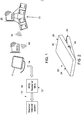
FIG. 1 is a schematic representation of an medical imaging device and/or system including a control device according to one exemplary non-limiting embodiment of the invention. -
FIG. 2 is an isometric view of a control device according to an exemplary non-limiting embodiment of the invention in a non-use configuration. -
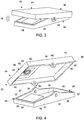
FIG. 3 is an isometric view of the control device ofFIG. 2 in a use configuration. -
FIG. 4 is an isometric exploded view of the control device ofFIG. 2 . -
FIG. 5 is an isometric exploded view of a control module according to another exemplary non-limiting embodiment of the invention. -
FIG. 6 is an isometric view of a control module according to still another exemplary non-limiting embodiment of the invention. - In the following detailed description, reference is made to the accompanying drawings that form a part hereof, and in which is shown by way of illustration specific embodiments, which may be practiced. These embodiments are described in sufficient detail to enable those skilled in the art to practice the embodiments, and it is to be understood that other embodiments may be utilized and that logical, mechanical, electrical and other changes may be made without departing from the scope of the embodiments. The following detailed description is, therefore, not to be taken in a limiting sense.
- Referring to
FIG. 1 , in the illustrated exemplary non-limiting embodiment amedical imaging system 10, such as a mammography or vascular imaging system, is operably connected to a radio frequency identification (RFID)reader 12. Thereader 12 is also operably connected via acable 14 or other suitable connector to anantenna 15 operably connected thereader 12 to thesystem 10. Thereader 12 additionally includes a microprocessor control unit (MCU) 16 that is configured to receiveoperational control signals 18 from an associatedRIFD tag 20 in response to querying/powering signals 64 emitted by theantenna 15 which is powered by thesystem 10 or can be independently powered. TheMCU 16 can interpret thesignals 18 received from thetags 20 via thereader 12 and can determine a function of thesystem 10 that is to be activated by in response to thesignals 18. This information is relayed from theMCU 16 to thesystem 10 in order to operate the function of thesystem 10 as desired. - Referring now to
FIGS. 1-4 , in the illustrated exemplary and non-limiting embodiment, theRFID tag 20 is disposed on acontrol device 22. Thecontrol device 22 can take a variety of forms and in the illustrated embodiment is formed as afootpedal 24. Thefootpedal 24 includes alower portion 26 formed of a rigid material, such as a plastic or non-metal, non-conductive material, and having abottom surface 28, a pair ofopposed end walls 30 extending upwardly therefrom and a pair ofsidewalls 32 extending upwardly from thebottom surface 28 between and connected to theend walls 30. Theside walls 32 each includes apivot aperture 34 formed therein at amidpoint 36 of theside walls 32. Further, each of theside walls 32 is formed withsloped sections 37 extending downwardly from themidpoint 36 to eachend wall 30, placing themidpoint 36 at the highest point of theside wall 32. - The
footpedal 24 also includes anupper portion 38 formed of a rigid material, such as a plastic or non-metal, non-conductive material, similarly to thelower portion 26 and including anupper surface 40, a pair ofend walls 42 extending downwardly from theupper surface 40 and a pair ofside walls 44 extending downwardly from and connected between theend walls 42. Theside walls 44 further includepivot openings 46 located at themidpoints 48 of theside walls 44. Theperimeter 50 of theupper portion 38 is slightly larger than theperimeter 52 of thelower portion 26 such that theend walls 42 andside walls 44 of theupper portion 38 can be positioned outside of thecorresponding end walls 32 andside walls 34 of thelower portion 26. In this position, thepivot apertures 34 are aligned with thepivot openings 46 and can receive apivot pin 54 therethrough to secure theupper portion 38 to thelower portion 26. Further, when secured to one another, thesloped sections 37 of theside walls 34 allows theupper portion 38 to be moved about thepivot pin 54 between angled positions on either side of themidpoint 36, as shown inFIGS. 2 and3 . - Looking now at
FIGS. 3 and 4 , thelower portion 26 of thefootpedal 22 additionally includes apedestal 56 disposed on thebottom surface 28 between theside walls 32 and adjacent oneend wall 30, such that thepedestal 56 is located to one side of themidpoint 36. Thepedestal 56 supports a metal sheet or coating 58 thereon. - On the
upper portion 38, theRFID tag 20 is disposed on theupper surface 40 between theside walls 44 and adjacent oneend wall 42, so as to position thetag 20 in alignment with themetal sheet 58 located on thepedestal 56. TheRFID tag 20 is apassive RFID tag 20, such that thetag 20 does not include any electronics, a printed circuit board (PCB), a wireless module or a battery. Thepassive RFID tag 20 is formed with a radio frequency (RF)antenna 60 with a small,unpowered chip 62 connected thereto that is operable within a specific range of frequencies of signals that are received by theantenna 60. When an querying/poweringsignal 64 within that frequency range sent from theantenna 15 is received by theantenna 60, theantenna 60 creates a magnetic field from which thechip 62 can derive power in order to send the information about thetag 20 and function of theimaging system 10 to be operated encoded on thechip 62 via a returnoperational control signal 18. - In operation of the
control device 22, thefootpedal 24 is initially placed within an area around the medical device orsystem 10 within easy reach of the physician performing the procedure. Thefootpedal 24 is initially configured such that theupper portion 38 is pivoted to position theRFID tag 20 immediately adjacent and/or in contact with themetal sheet 58 disposed on thepedestal 56 of thelower portion 26. Themetal sheet 58 and the parts of thelower portion 26 andupper portion 38 to which thetag 20 is secured act a shield/shielding member for thetag 20 according to the Faraday cage principle, preventing the signal emanating from thereader 12 from reaching thetag 20. Theupper portion 38 can be biased to remain in the configuration where thetag 20 is shielded by themetal sheet 58, such as by weighting theupper portion 38 or providing a suitable biasing member (not shown) between theupper portion 38 and thelower portion 26. In this configuration, the querying/powering signals emanating from theantenna 15 are not received by thetag 20, as thetag 20 is shielded by the shielding enclosure provided or formed by theupper portion 38, thelower portion 26 and/or themetal sheet 58, and no correspondingsignal 18 from thetag 20 is received by thereader 12 in order to operate the selected function of thesystem 10. - When the physician desires to active the function of the
system 10 controlled by thecontrol device 22, the physician can depress or pivot theupper portion 38 relative to thelower portion 26 to move thetag 20 away from themetal sheet 58, exposing or unshielding thetag 20 to the querying/poweringsignal 64 from theantenna 15 Thesignal 64 is received by thepassive tag 20 and powers and causes thechip 62 thereon to send the correspondingoperational signal 18 to thereader 12. Theoperational signal 18 received by thereader 12 is utilized by theMCU 16 to operate the associated function of thesystem 10 as desired by the physician. Depending upon the particular function of thesystem 10 being controlled, the physician can operate thecontrol device 22 by depressing and releasing theupper portion 38 of thefootpedal 24, by depressing and holding theupper portion 38 in the depressed position, or by depressing theupper portion 38 in a predetermined pattern to provide a desired activation or operation pattern of the function of thesystem 10 being controlled. - In additional non-limiting exemplary embodiments, the
control device 22 can utilize other methods for shielding thetags 20, such as by unrolling thetags 20 from a metal enclosing roll upon actuation of thecontrol device 22, or by moving thetags 22 out of a metal enclosure (not shown) upon actuation of thecontrol device 22, such as by depressing theupper portion 38 of thefootpedal 24. - In addition to directly controlling the function of the
system 10, the actuation of thecontrol device 22 can be utilized in an alternative non-limiting exemplary embodiment as a switch for themedical device 10. For example, upon depressing the footpedal 24, the exposure of thetag 20 to thesignal 64 from thereader 12 causes thetag 20 to emit thesignal 18 to be received by thereader 12. Thissignal 18 can be utilized by thereader 12 to indicate to thesystem 10 the status of a switch (not shown) for thesystem 10, such as whether the switch is to be considered activated. Thus, thecontrol device 22 can be utilized as a remote activation of a switch on thesystem 10 for a function of thesystem 10, whether or not thesystem 10 has an actual swtich for the particular function. In addition by having two switches (not shown) associated with thecontrol device 22, redundancy can be achieved. This is accomplished as the status of both the switches would be sent along with thetag id signal 18 which would be sensed by thereader 12. Thus, only when both the switches are activated and thesignal 18 is received by thereader 12 would thesystem 10 activate the function. In an alternative embodiment, the status of two separate switches/control device 22 are embedded withtag data 18 ontags 20 assoited with each switch/control device 22. For thereader 12 to read the switch status, tag 20 should be exposed and read. This embodiment is applicable to bothsystems 10 with and without metal shielding 58. If there is no metal shielding 58 on theswitch 22, thetag 20 will be continually exposed but thesystem 10 will not perform the required operation until unless both theswitches 22 are pressed, i.e., bothtags 20 are simultaneously exposed or covered. In this embodiment the main concern is the use of the twoswitches 22 to avoid single fault condition that can be causes where single switch/control device 22 is utilized. - Looking now at
FIG. 5 in another illustrated non-limiting exemplary embodiment, the control device 22' is illustrated in which the upper portion 38' includes a pair of tags 20' located on the upper surface 40' with a corresponding pair of pedestals 56' and metal sheets 58' located on the bottom surface 28' of lower portion 26'. In this control device 22', one tag 20' is always in an exposed position such that thereader 12 will receive asignal 18 from one of the tags 20' regardless of the positon of the upper portion 38'. One tag 20' is identified with the operation of the selected function of thesystem 10, while the other tag 20' is identified with the non-operation of the selected system function. Thus, when theupper portion 38 of thepedal 24 is depressed/operated to expose the tag 20' corresponding to the operation of the function, the tag 20' corresponding to the non-operation of that function is simultaneously shielded. In this manner, thecontrol device 22 provides redundancy in the operation of the device 22' to avoid unwanted activation of the system function in the situation where neither or both of the tags 20' emit signals that are received by thereader 12, such as in the following Table showing the operational conditions illustrated by the sensing of the tags 20', where a 1 indicates the tag 20' is sensed by thereader 12 and a 0 indicated the tag 20' is not sensed by the reader 12:Table 1: Output Configurations of Multiple Tag Control Device Tag 1 Tag 2 Output to System Condition 0 0 0 (both tags not sensed) Fault 0 1 0 Normal (unactuated) 1 0 1 Pedal Actuated 1 1 0 (both tags sensed) Fault - Referring now to
FIG. 6 in another illustrated non-limiting exemplary embodiment thecontrol device 122 can include acentral platform 166 mounted to a number ofsupports 168. Atag 170 is disposed on anupper surface 172 and alower surface 174 of theplatform 166. Shielding members 177 are disposed adjacent theupper surface 172 and thelower surface 174 onmovable panels 176 that are interconnected with one another bybraces 178 that are disposed between and outside of the perimeter of thesupports 168. Thebraces 178 enable thepanels 176 supporting the shielding members 177 to move in conjunction with one another against the bias of a biasing member (not shown) engaged between thepanels 176 and theplatform 166 to bias the shielding members 177 toward thelower surface 174, thus exposing thetag 170 located on theupper surface 172, which can be thetag 170 associated with the non-operation of the system function. Thus, when a user applies a force against theupper panel 176 against the bias of the biasing member, thepanel 176 and corresponding lower shielding member 177 is displaced from thelower surface 174, exposing thetag 170 thereon, while theupper panel 176 and corresponding shielding member 177 simultaneously covers and shields thetag 170 on theupper surface 172. In this manner, thetag 170 on thelower surface 174 is exposed and transmits thesignal 18 corresponding to the operation of the associated system function. In an alternative and non-limiting exemplary embodiment, the positons of thetags 170 and the shielding members 177 can be reversed, with the shielding members 177 being disposed on theupper surface 172 andlower surface 174 of theplatform 166 and thetags 170 located adjacent theupper surface 172 and/orlower surface 174 on themovable panels 176. - The written description uses examples to disclose the invention, including the preferred mode, and also to enable any person skilled in the art to practice the invention, including making and using any devices or systems and performing any incorporated methods. The patentable scope of the invention is defined by the claims, and may include other examples that occur to those skilled in the art. Such other examples are intended to be within the scope of the claims if they have structural elements that do not differ from the literal language of the claims, or if they include equivalent structural elements with insubstantial differences from the literal language of the claims.
- Various aspects and embodiments of the present invention are defined by the following numbered clauses:
- 1. A control device for operating a function of a medical system, the control device comprising:
- a lower portion;
- an upper portion movably connected to the lower portion; and
- an identification device adapted to communicate wirelessly with the medical device disposed on one of the lower or upper portion, wherein the control device does not include a power source.
- 2. The control device of clause 1, wherein the control device does not include an electronic component or wireless transmission module.
- 3. The control device of any preceding clause, wherein the identification device is a passive identification device.
- 4. The control device of any preceding clause, wherein the passive identification device is a passive RFID tag.
- 5. The control device of any preceding clause, further comprising at least one shielding member disposed on one of the lower portion or the upper portion.
- 6. The control device of any preceding clause, wherein the at least one shielding member is the upper portion.
- 7. The control device of any preceding clause, wherein the at least one shielding member is a metal sheet disposed on the lower portion.
- 8. The control device of any preceding clause, wherein the metal sheet is disposed on a pedestal located on the lower portion in selective alignment with the identification device.
- 9. The control device of any preceding clause, further comprising a number of identification devices disposed on one of the upper portion or lower portion.
- 10. The control device of any preceding clause, where the upper portion is pivotally connected to the lower portion.
- 11. A medical system comprising:
- an imaging system;
- an identification device reader operably connected to the imaging system; and
- a control device including an identification device operably connectable to the identification device reader to operate a function of the imaging system, wherein the control device is entirely passive.
- 12. The medical system of any preceding clause, wherein the control device does not include a power source, a printed circuit board or a wireless communication module.
- 13. The medical system of any preceding clause, wherein the identification device is a passive RFID tag.
- 14. The medical system of any preceding clause, wherein the control device forms a shielding enclosure around the identification device.
- 15. The medical system of any preceding clause, wherein the shielding enclosure is selectively openable to expose the identification device to a signal from the identification device reader.
- 16. The medical system of any preceding clause, further comprising multiple identification devices on the control device, each identification device being selectively exposed to operate a particular function of the imaging system.
- 17. The medical system of any preceding clause, where in the multiple identification devices are disposed on multiple control devices that are operated in conjunction with one another to provide redundancy of the control the operation of the particular function of the imaging system.
- 18. A method of controlling the operation of a function of a medical system during a medical procedure, the method comprising the steps of:
- providing medical system comprising an imaging system, an identification device reader operably connected to the imaging system and a control device including an identification device operably connectable to the identification device reader to operate a function of the imaging system, wherein the control device is entirely passive;
- unshielding the identification device to a signal from the identification device reader;
- receiving at the reader an operational control signal from the identification device; and
- controlling operation of a function of the medical system in response to the control signal.
- 19. The method of any preceding clause, wherein the control device forms a shielding enclosure around the identification device and wherein the step of unshielding the identification device comprises opening the shielding enclosure.
- 20. The method of any preceding clause, wherein the control device includes a lower portion and an upper portion movably connected to the lower portion, and wherein the step of unshielding the identification device comprises moving the upper portion relative to the lower portion.
Claims (15)
- A control device (22) for operating a function of a medical system, the control device comprising:a lower portion (26);an upper portion (24) movably connected to the lower portion; andan identification device adapted to communicate wirelessly with the medical device disposed on one of the lower or upper portion, wherein the control device does not include a power source.
- The control device (22) of claim 1, wherein the control device does not include an electronic component or wireless transmission module.
- The control device (22) of any preceding claim. wherein the identification device is a passive identification device.
- The control device (22) of claim 3, wherein the passive identification device is a passive RFID tag.
- The control device (22) of any preceding claim, further comprising at least one shielding member disposed on one of the lower portion or the upper portion.
- The control device (22) of claim 5, wherein the at least one shielding member is the upper portion.
- The control device (22) of claim 5 or claim 6, wherein the at least one shielding member is a metal sheet disposed on the lower portion.
- The control device (22) of any preceding claim, wherein the metal sheet is disposed on a pedestal located on the lower portion in selective alignment with the identification device.
- The control device (22) of any preceding claim, further comprising a number of identification devices disposed on one of the upper portion or lower portion.
- The control device (22) of any preceding claim, where the upper portion is pivotally connected to the lower portion.
- A medical system comprising:an imaging system;an identification device reader operably connected to the imaging system; anda control device (22) including an identification device operably connectable to the identification device reader to operate a function of the imaging system, wherein the control device is entirely passive.
- The medical system of claim 11, wherein the control device (22) does not include a power source, a printed circuit board or a wireless communication module.
- A method of controlling the operation of a function of a medical system during a medical procedure, the method comprising the steps of:providing medical system comprising an imaging system, an identification device reader operably connected to the imaging system and a control device (22) including an identification device operably connectable to the identification device reader to operate a function of the imaging system, wherein the control device is entirely passive;unshielding the identification device to a signal from the identification device reader;receiving at the reader an operational control signal from the identification device; andcontrolling operation of a function of the medical system in response to the control signal.
- The method of claim 13, wherein the control device (22) forms a shielding enclosure around the identification device and wherein the step of unshielding the identification device comprises opening the shielding enclosure.
- The method of claim 13 or claim 14, wherein the control device (22) includes a lower portion and an upper portion movably connected to the lower portion, and wherein the step of unshielding the identification device comprises moving the upper portion relative to the lower portion.
Applications Claiming Priority (1)
| Application Number | Priority Date | Filing Date | Title |
|---|---|---|---|
| US15/333,739 US10438697B2 (en) | 2016-10-25 | 2016-10-25 | Passive wireless footpedal for medical applications |
Publications (2)
| Publication Number | Publication Date |
|---|---|
| EP3315080A1 true EP3315080A1 (en) | 2018-05-02 |
| EP3315080B1 EP3315080B1 (en) | 2025-09-10 |
Family
ID=57754972
Family Applications (1)
| Application Number | Title | Priority Date | Filing Date |
|---|---|---|---|
| EP16204700.5A Active EP3315080B1 (en) | 2016-10-25 | 2016-12-16 | Passive wireless footpedal for medical applications |
Country Status (3)
| Country | Link |
|---|---|
| US (1) | US10438697B2 (en) |
| EP (1) | EP3315080B1 (en) |
| CN (1) | CN107970073B (en) |
Cited By (3)
| Publication number | Priority date | Publication date | Assignee | Title |
|---|---|---|---|---|
| EP3363402A1 (en) * | 2017-02-21 | 2018-08-22 | Karl Storz SE & Co. KG | Medicine device and medical system and use of an rfid tag |
| US10438697B2 (en) * | 2016-10-25 | 2019-10-08 | General Electric Company | Passive wireless footpedal for medical applications |
| DE102021127724A1 (en) | 2021-10-25 | 2023-04-27 | Vega Grieshaber Kg | sensor |
Families Citing this family (2)
| Publication number | Priority date | Publication date | Assignee | Title |
|---|---|---|---|---|
| CN113314210A (en) * | 2021-07-08 | 2021-08-27 | 中国人民解放军联勤保障部队第九〇九医院 | Passive wireless medical foot brake and control method thereof |
| JP2025526203A (en) * | 2022-08-16 | 2025-08-12 | アルコン インコーポレイティド | Inductively Coupled Foot Pedal Battery Charging |
Citations (9)
| Publication number | Priority date | Publication date | Assignee | Title |
|---|---|---|---|---|
| US20030016136A1 (en) * | 2001-07-20 | 2003-01-23 | Delta Systems, Inc. | Radio frequency powered switch |
| US20060165371A1 (en) * | 2002-10-18 | 2006-07-27 | Koninklijke Philips Electronics, N.V. | Medical examination system |
| US20070194100A1 (en) * | 2006-02-14 | 2007-08-23 | Brainlab Ag | Remote control system for sequence control in medical treatment... |
| EP2178023A2 (en) * | 2008-09-30 | 2010-04-21 | Rockwell Automation Technologies, Inc. | RFID based contact position indication |
| US20100179542A1 (en) * | 2009-01-13 | 2010-07-15 | Tyco Healthcare Group Lp | Method for Wireless Control of Electrosurgery |
| US20150220763A1 (en) * | 2014-02-04 | 2015-08-06 | Klaus Porzelt | Control Device, Medical Control System and Method for Transmitting a Command |
| US20150250439A1 (en) * | 2014-03-04 | 2015-09-10 | Kabushiki Kaisha Toshiba | Wireless foot switch and x-ray diagnosis system |
| US20150342677A1 (en) * | 2014-05-29 | 2015-12-03 | The Spectranetics Corporation | Remote control switch for a laser system |
| EP3041011A1 (en) * | 2014-12-29 | 2016-07-06 | Eaton Corporation | Control system including a switch with integrated rfid tag |
Family Cites Families (24)
| Publication number | Priority date | Publication date | Assignee | Title |
|---|---|---|---|---|
| US4313258A (en) * | 1979-10-18 | 1982-02-02 | General Electric Company | Methods and apparatus for use in making electrical interconnections |
| DE102005013063A1 (en) | 2004-03-31 | 2005-11-03 | Carl Zeiss Meditec Ag | Wireless operation microscope control procedure uses separate control unit with wireless power supply |
| KR100614319B1 (en) | 2004-04-29 | 2006-08-18 | 엘지.필립스 엘시디 주식회사 | LCD Display Module |
| US7568619B2 (en) * | 2004-12-15 | 2009-08-04 | Alcon, Inc. | System and method for identifying and controlling ophthalmic surgical devices and components |
| US8565839B2 (en) * | 2005-10-13 | 2013-10-22 | Abbott Medical Optics Inc. | Power management for wireless devices |
| US8380126B1 (en) * | 2005-10-13 | 2013-02-19 | Abbott Medical Optics Inc. | Reliable communications for wireless devices |
| DE102005054230A1 (en) * | 2005-11-14 | 2007-05-24 | Maquet Gmbh & Co. Kg | Method and device for bidirectional IR data transmission between an operating table and an operating device |
| US20070114366A1 (en) * | 2005-11-21 | 2007-05-24 | General Electric Company | Optical article having a multi-component structure as an anti-theft feature and a system and method for inhibiting theft of same |
| US7737849B2 (en) | 2006-07-07 | 2010-06-15 | Chung Hua University | Switch detection device using RFID tag |
| US9658178B2 (en) * | 2012-09-28 | 2017-05-23 | General Electric Company | Sensor systems for measuring an interface level in a multi-phase fluid composition |
| US8083735B2 (en) * | 2006-11-17 | 2011-12-27 | Genii, Inc. | Compact electrosurgery apparatuses |
| US8768251B2 (en) * | 2007-05-17 | 2014-07-01 | Abbott Medical Optics Inc. | Exclusive pairing technique for Bluetooth compliant medical devices |
| US8750796B2 (en) * | 2007-05-17 | 2014-06-10 | Abbott Medical Optics Inc. | Exclusive pairing technique for short-range communication devices |
| US8808319B2 (en) * | 2007-07-27 | 2014-08-19 | Ethicon Endo-Surgery, Inc. | Surgical instruments |
| US7834322B2 (en) * | 2007-07-27 | 2010-11-16 | Fujifilm Corporation | Radiation image capturing system |
| DE102008061418A1 (en) | 2007-12-12 | 2009-06-18 | Erbe Elektromedizin Gmbh | Apparatus for contactless communication and use of a memory device |
| EP2279028A2 (en) * | 2008-05-07 | 2011-02-02 | Sanuwave, Inc. | Medical treatment system including an ancillary medical treatment apparatus with an associated data storage medium |
| US8159370B2 (en) | 2008-11-17 | 2012-04-17 | Canyon Ridge Resources, Llc | System and method for control of medical equipment using multiple wireless devices |
| US8274610B2 (en) | 2009-09-29 | 2012-09-25 | Sony Corporation | RFID-based wireless remote control using variable ID field |
| DE102010006845B4 (en) | 2010-02-03 | 2019-05-16 | Leica Microsystems (Schweiz) Ag | Medical device with wireless foot switch |
| CN102068311A (en) * | 2010-12-27 | 2011-05-25 | 李彬清 | Medical surgery-assisting navigation and photodynamic biochemical analysis system |
| DE102014209806A1 (en) * | 2014-05-22 | 2015-11-26 | Siemens Aktiengesellschaft | Method and device for a wireless transmission of pacemaker signals |
| US10438697B2 (en) * | 2016-10-25 | 2019-10-08 | General Electric Company | Passive wireless footpedal for medical applications |
| US10646394B2 (en) * | 2017-04-21 | 2020-05-12 | Johnson & Johnson Surgical Vision, Inc. | Apparatus, system and method of providing a foot pedal platform for ophthalmic surgery |
-
2016
- 2016-10-25 US US15/333,739 patent/US10438697B2/en active Active
- 2016-12-16 EP EP16204700.5A patent/EP3315080B1/en active Active
- 2016-12-30 CN CN201611261121.7A patent/CN107970073B/en active Active
Patent Citations (9)
| Publication number | Priority date | Publication date | Assignee | Title |
|---|---|---|---|---|
| US20030016136A1 (en) * | 2001-07-20 | 2003-01-23 | Delta Systems, Inc. | Radio frequency powered switch |
| US20060165371A1 (en) * | 2002-10-18 | 2006-07-27 | Koninklijke Philips Electronics, N.V. | Medical examination system |
| US20070194100A1 (en) * | 2006-02-14 | 2007-08-23 | Brainlab Ag | Remote control system for sequence control in medical treatment... |
| EP2178023A2 (en) * | 2008-09-30 | 2010-04-21 | Rockwell Automation Technologies, Inc. | RFID based contact position indication |
| US20100179542A1 (en) * | 2009-01-13 | 2010-07-15 | Tyco Healthcare Group Lp | Method for Wireless Control of Electrosurgery |
| US20150220763A1 (en) * | 2014-02-04 | 2015-08-06 | Klaus Porzelt | Control Device, Medical Control System and Method for Transmitting a Command |
| US20150250439A1 (en) * | 2014-03-04 | 2015-09-10 | Kabushiki Kaisha Toshiba | Wireless foot switch and x-ray diagnosis system |
| US20150342677A1 (en) * | 2014-05-29 | 2015-12-03 | The Spectranetics Corporation | Remote control switch for a laser system |
| EP3041011A1 (en) * | 2014-12-29 | 2016-07-06 | Eaton Corporation | Control system including a switch with integrated rfid tag |
Cited By (3)
| Publication number | Priority date | Publication date | Assignee | Title |
|---|---|---|---|---|
| US10438697B2 (en) * | 2016-10-25 | 2019-10-08 | General Electric Company | Passive wireless footpedal for medical applications |
| EP3363402A1 (en) * | 2017-02-21 | 2018-08-22 | Karl Storz SE & Co. KG | Medicine device and medical system and use of an rfid tag |
| DE102021127724A1 (en) | 2021-10-25 | 2023-04-27 | Vega Grieshaber Kg | sensor |
Also Published As
| Publication number | Publication date |
|---|---|
| EP3315080B1 (en) | 2025-09-10 |
| US20180113983A1 (en) | 2018-04-26 |
| CN107970073A (en) | 2018-05-01 |
| CN107970073B (en) | 2022-07-12 |
| US10438697B2 (en) | 2019-10-08 |
Similar Documents
| Publication | Publication Date | Title |
|---|---|---|
| US10438697B2 (en) | Passive wireless footpedal for medical applications | |
| US11710984B2 (en) | Wireless charging system with simultaneous wireless power transfer at different frequencies | |
| US8638191B2 (en) | Wireless hand-control of device by means of wireless button | |
| US9940569B2 (en) | RFID tag assembly and surgical instrument | |
| CN102891674B (en) | Switching device for Medical Devices and the method for installation switching device | |
| US9776839B2 (en) | Control station for operating a machine, in particular a wireless, portable, and manually operated remote control for a crane | |
| JP4929390B1 (en) | Electronic equipment and antenna unit | |
| JP2022526104A (en) | Connector that provides connectivity through a flexible barrier | |
| US20100123604A1 (en) | System and method for control of medical equipment using multiple wireless devices | |
| US9999468B2 (en) | Remote control switch for a laser system | |
| JP2005108245A (en) | Rfid sensor system and rfid detection method | |
| EP2349005A2 (en) | System and method for wireless control of medical devices | |
| EP3648484B1 (en) | Identification of device location in healthcare facility | |
| CN1134908C (en) | Mobile communication device and method of disconnecting its power supply | |
| EP1278265A3 (en) | Highly integrated planar stacked millimeter wave transceiver | |
| TW200814978A (en) | Smart connector system for surgical machine | |
| GB2538447A (en) | Antenna equipment and electronic device | |
| KR20120002207A (en) | Ubiquitous switchgear with smart remote control door | |
| KR100769540B1 (en) | Loop type antenna having dual structure of wireless identification tag and reader and short range communication transmitting / receiving system using same | |
| US6304246B1 (en) | Input device for shifting a marker on a monitor screen | |
| WO2007113884A1 (en) | Method and connection equipment for connecting the central unit and the peripheral units of an operating table, and operating table incorporating such equipment for implementing the method | |
| EP3440596B1 (en) | Modular radio frequency identification (rfid) devices | |
| JP7510486B2 (en) | Medical Devices with Galvanic Isolation Devices | |
| US20130029615A1 (en) | Antenna apparatus and wireless communication apparatus | |
| CN116264763B (en) | Medical device with electrical isolation means |
Legal Events
| Date | Code | Title | Description |
|---|---|---|---|
| PUAI | Public reference made under article 153(3) epc to a published international application that has entered the european phase |
Free format text: ORIGINAL CODE: 0009012 |
|
| STAA | Information on the status of an ep patent application or granted ep patent |
Free format text: STATUS: THE APPLICATION HAS BEEN PUBLISHED |
|
| AK | Designated contracting states |
Kind code of ref document: A1 Designated state(s): AL AT BE BG CH CY CZ DE DK EE ES FI FR GB GR HR HU IE IS IT LI LT LU LV MC MK MT NL NO PL PT RO RS SE SI SK SM TR |
|
| AX | Request for extension of the european patent |
Extension state: BA ME |
|
| STAA | Information on the status of an ep patent application or granted ep patent |
Free format text: STATUS: REQUEST FOR EXAMINATION WAS MADE |
|
| 17P | Request for examination filed |
Effective date: 20181102 |
|
| RBV | Designated contracting states (corrected) |
Designated state(s): AL AT BE BG CH CY CZ DE DK EE ES FI FR GB GR HR HU IE IS IT LI LT LU LV MC MK MT NL NO PL PT RO RS SE SI SK SM TR |
|
| STAA | Information on the status of an ep patent application or granted ep patent |
Free format text: STATUS: EXAMINATION IS IN PROGRESS |
|
| 17Q | First examination report despatched |
Effective date: 20200218 |
|
| P01 | Opt-out of the competence of the unified patent court (upc) registered |
Effective date: 20230528 |
|
| GRAP | Despatch of communication of intention to grant a patent |
Free format text: ORIGINAL CODE: EPIDOSNIGR1 |
|
| STAA | Information on the status of an ep patent application or granted ep patent |
Free format text: STATUS: GRANT OF PATENT IS INTENDED |
|
| INTG | Intention to grant announced |
Effective date: 20250409 |
|
| RAP1 | Party data changed (applicant data changed or rights of an application transferred) |
Owner name: GE PRECISION HEALTHCARE LLC |
|
| GRAS | Grant fee paid |
Free format text: ORIGINAL CODE: EPIDOSNIGR3 |
|
| GRAA | (expected) grant |
Free format text: ORIGINAL CODE: 0009210 |
|
| STAA | Information on the status of an ep patent application or granted ep patent |
Free format text: STATUS: THE PATENT HAS BEEN GRANTED |
|
| AK | Designated contracting states |
Kind code of ref document: B1 Designated state(s): AL AT BE BG CH CY CZ DE DK EE ES FI FR GB GR HR HU IE IS IT LI LT LU LV MC MK MT NL NO PL PT RO RS SE SI SK SM TR |
|
| REG | Reference to a national code |
Ref country code: GB Ref legal event code: FG4D |
|
| REG | Reference to a national code |
Ref country code: CH Ref legal event code: EP |
|
| REG | Reference to a national code |
Ref country code: DE Ref legal event code: R096 Ref document number: 602016093522 Country of ref document: DE |
|
| REG | Reference to a national code |
Ref country code: IE Ref legal event code: FG4D |
|
| PGFP | Annual fee paid to national office [announced via postgrant information from national office to epo] |
Ref country code: DE Payment date: 20251126 Year of fee payment: 10 |
|
| PGFP | Annual fee paid to national office [announced via postgrant information from national office to epo] |
Ref country code: GB Payment date: 20251119 Year of fee payment: 10 |
|
| PG25 | Lapsed in a contracting state [announced via postgrant information from national office to epo] |
Ref country code: NO Free format text: LAPSE BECAUSE OF FAILURE TO SUBMIT A TRANSLATION OF THE DESCRIPTION OR TO PAY THE FEE WITHIN THE PRESCRIBED TIME-LIMIT Effective date: 20251210 |
|
| REG | Reference to a national code |
Ref country code: LT Ref legal event code: MG9D |
|
| PG25 | Lapsed in a contracting state [announced via postgrant information from national office to epo] |
Ref country code: FI Free format text: LAPSE BECAUSE OF FAILURE TO SUBMIT A TRANSLATION OF THE DESCRIPTION OR TO PAY THE FEE WITHIN THE PRESCRIBED TIME-LIMIT Effective date: 20250910 |
|
| REG | Reference to a national code |
Ref country code: NL Ref legal event code: MP Effective date: 20250910 |
|
| PG25 | Lapsed in a contracting state [announced via postgrant information from national office to epo] |
Ref country code: HR Free format text: LAPSE BECAUSE OF FAILURE TO SUBMIT A TRANSLATION OF THE DESCRIPTION OR TO PAY THE FEE WITHIN THE PRESCRIBED TIME-LIMIT Effective date: 20250910 |
|
| PG25 | Lapsed in a contracting state [announced via postgrant information from national office to epo] |
Ref country code: GR Free format text: LAPSE BECAUSE OF FAILURE TO SUBMIT A TRANSLATION OF THE DESCRIPTION OR TO PAY THE FEE WITHIN THE PRESCRIBED TIME-LIMIT Effective date: 20251211 |
|
| PG25 | Lapsed in a contracting state [announced via postgrant information from national office to epo] |
Ref country code: SE Free format text: LAPSE BECAUSE OF FAILURE TO SUBMIT A TRANSLATION OF THE DESCRIPTION OR TO PAY THE FEE WITHIN THE PRESCRIBED TIME-LIMIT Effective date: 20250910 |
|
| PG25 | Lapsed in a contracting state [announced via postgrant information from national office to epo] |
Ref country code: LV Free format text: LAPSE BECAUSE OF FAILURE TO SUBMIT A TRANSLATION OF THE DESCRIPTION OR TO PAY THE FEE WITHIN THE PRESCRIBED TIME-LIMIT Effective date: 20250910 |
|
| PG25 | Lapsed in a contracting state [announced via postgrant information from national office to epo] |
Ref country code: BG Free format text: LAPSE BECAUSE OF FAILURE TO SUBMIT A TRANSLATION OF THE DESCRIPTION OR TO PAY THE FEE WITHIN THE PRESCRIBED TIME-LIMIT Effective date: 20250910 Ref country code: PL Free format text: LAPSE BECAUSE OF FAILURE TO SUBMIT A TRANSLATION OF THE DESCRIPTION OR TO PAY THE FEE WITHIN THE PRESCRIBED TIME-LIMIT Effective date: 20250910 |
|
| PG25 | Lapsed in a contracting state [announced via postgrant information from national office to epo] |
Ref country code: RS Free format text: LAPSE BECAUSE OF FAILURE TO SUBMIT A TRANSLATION OF THE DESCRIPTION OR TO PAY THE FEE WITHIN THE PRESCRIBED TIME-LIMIT Effective date: 20251210 |
|
| PG25 | Lapsed in a contracting state [announced via postgrant information from national office to epo] |
Ref country code: ES Free format text: LAPSE BECAUSE OF FAILURE TO SUBMIT A TRANSLATION OF THE DESCRIPTION OR TO PAY THE FEE WITHIN THE PRESCRIBED TIME-LIMIT Effective date: 20250910 |
|
| REG | Reference to a national code |
Ref country code: AT Ref legal event code: MK05 Ref document number: 1835024 Country of ref document: AT Kind code of ref document: T Effective date: 20250910 |
|
| PG25 | Lapsed in a contracting state [announced via postgrant information from national office to epo] |
Ref country code: NL Free format text: LAPSE BECAUSE OF FAILURE TO SUBMIT A TRANSLATION OF THE DESCRIPTION OR TO PAY THE FEE WITHIN THE PRESCRIBED TIME-LIMIT Effective date: 20250910 |
|
| PG25 | Lapsed in a contracting state [announced via postgrant information from national office to epo] |
Ref country code: SM Free format text: LAPSE BECAUSE OF FAILURE TO SUBMIT A TRANSLATION OF THE DESCRIPTION OR TO PAY THE FEE WITHIN THE PRESCRIBED TIME-LIMIT Effective date: 20250910 |
|
| PG25 | Lapsed in a contracting state [announced via postgrant information from national office to epo] |
Ref country code: AT Free format text: LAPSE BECAUSE OF FAILURE TO SUBMIT A TRANSLATION OF THE DESCRIPTION OR TO PAY THE FEE WITHIN THE PRESCRIBED TIME-LIMIT Effective date: 20250910 |
|
| PG25 | Lapsed in a contracting state [announced via postgrant information from national office to epo] |
Ref country code: IT Free format text: LAPSE BECAUSE OF FAILURE TO SUBMIT A TRANSLATION OF THE DESCRIPTION OR TO PAY THE FEE WITHIN THE PRESCRIBED TIME-LIMIT Effective date: 20250910 Ref country code: RO Free format text: LAPSE BECAUSE OF FAILURE TO SUBMIT A TRANSLATION OF THE DESCRIPTION OR TO PAY THE FEE WITHIN THE PRESCRIBED TIME-LIMIT Effective date: 20250910 |
|
| PG25 | Lapsed in a contracting state [announced via postgrant information from national office to epo] |
Ref country code: IS Free format text: LAPSE BECAUSE OF FAILURE TO SUBMIT A TRANSLATION OF THE DESCRIPTION OR TO PAY THE FEE WITHIN THE PRESCRIBED TIME-LIMIT Effective date: 20260110 |
|
| PG25 | Lapsed in a contracting state [announced via postgrant information from national office to epo] |
Ref country code: PT Free format text: LAPSE BECAUSE OF FAILURE TO SUBMIT A TRANSLATION OF THE DESCRIPTION OR TO PAY THE FEE WITHIN THE PRESCRIBED TIME-LIMIT Effective date: 20260112 Ref country code: CZ Free format text: LAPSE BECAUSE OF FAILURE TO SUBMIT A TRANSLATION OF THE DESCRIPTION OR TO PAY THE FEE WITHIN THE PRESCRIBED TIME-LIMIT Effective date: 20250910 |
|
| PG25 | Lapsed in a contracting state [announced via postgrant information from national office to epo] |
Ref country code: SK Free format text: LAPSE BECAUSE OF FAILURE TO SUBMIT A TRANSLATION OF THE DESCRIPTION OR TO PAY THE FEE WITHIN THE PRESCRIBED TIME-LIMIT Effective date: 20250910 Ref country code: EE Free format text: LAPSE BECAUSE OF FAILURE TO SUBMIT A TRANSLATION OF THE DESCRIPTION OR TO PAY THE FEE WITHIN THE PRESCRIBED TIME-LIMIT Effective date: 20250910 |