EP3314909B1 - Noise cancellation system arraying speakers for a uniform driver field - Google Patents
Noise cancellation system arraying speakers for a uniform driver field Download PDFInfo
- Publication number
- EP3314909B1 EP3314909B1 EP16734135.3A EP16734135A EP3314909B1 EP 3314909 B1 EP3314909 B1 EP 3314909B1 EP 16734135 A EP16734135 A EP 16734135A EP 3314909 B1 EP3314909 B1 EP 3314909B1
- Authority
- EP
- European Patent Office
- Prior art keywords
- signal
- speaker
- speakers
- phase
- arrayed
- Prior art date
- Legal status (The legal status is an assumption and is not a legal conclusion. Google has not performed a legal analysis and makes no representation as to the accuracy of the status listed.)
- Active
Links
Images




Classifications
-
- G—PHYSICS
- G10—MUSICAL INSTRUMENTS; ACOUSTICS
- G10K—SOUND-PRODUCING DEVICES; METHODS OR DEVICES FOR PROTECTING AGAINST, OR FOR DAMPING, NOISE OR OTHER ACOUSTIC WAVES IN GENERAL; ACOUSTICS NOT OTHERWISE PROVIDED FOR
- G10K11/00—Methods or devices for transmitting, conducting or directing sound in general; Methods or devices for protecting against, or for damping, noise or other acoustic waves in general
- G10K11/16—Methods or devices for protecting against, or for damping, noise or other acoustic waves in general
- G10K11/175—Methods or devices for protecting against, or for damping, noise or other acoustic waves in general using interference effects; Masking sound
- G10K11/178—Methods or devices for protecting against, or for damping, noise or other acoustic waves in general using interference effects; Masking sound by electro-acoustically regenerating the original acoustic waves in anti-phase
- G10K11/1783—Methods or devices for protecting against, or for damping, noise or other acoustic waves in general using interference effects; Masking sound by electro-acoustically regenerating the original acoustic waves in anti-phase handling or detecting of non-standard events or conditions, e.g. changing operating modes under specific operating conditions
- G10K11/17833—Methods or devices for protecting against, or for damping, noise or other acoustic waves in general using interference effects; Masking sound by electro-acoustically regenerating the original acoustic waves in anti-phase handling or detecting of non-standard events or conditions, e.g. changing operating modes under specific operating conditions by using a self-diagnostic function or a malfunction prevention function, e.g. detecting abnormal output levels
- G10K11/17835—Methods or devices for protecting against, or for damping, noise or other acoustic waves in general using interference effects; Masking sound by electro-acoustically regenerating the original acoustic waves in anti-phase handling or detecting of non-standard events or conditions, e.g. changing operating modes under specific operating conditions by using a self-diagnostic function or a malfunction prevention function, e.g. detecting abnormal output levels using detection of abnormal input signals
-
- G—PHYSICS
- G10—MUSICAL INSTRUMENTS; ACOUSTICS
- G10K—SOUND-PRODUCING DEVICES; METHODS OR DEVICES FOR PROTECTING AGAINST, OR FOR DAMPING, NOISE OR OTHER ACOUSTIC WAVES IN GENERAL; ACOUSTICS NOT OTHERWISE PROVIDED FOR
- G10K11/00—Methods or devices for transmitting, conducting or directing sound in general; Methods or devices for protecting against, or for damping, noise or other acoustic waves in general
- G10K11/16—Methods or devices for protecting against, or for damping, noise or other acoustic waves in general
- G10K11/175—Methods or devices for protecting against, or for damping, noise or other acoustic waves in general using interference effects; Masking sound
- G10K11/178—Methods or devices for protecting against, or for damping, noise or other acoustic waves in general using interference effects; Masking sound by electro-acoustically regenerating the original acoustic waves in anti-phase
- G10K11/1781—Methods or devices for protecting against, or for damping, noise or other acoustic waves in general using interference effects; Masking sound by electro-acoustically regenerating the original acoustic waves in anti-phase characterised by the analysis of input or output signals, e.g. frequency range, modes, transfer functions
- G10K11/17813—Methods or devices for protecting against, or for damping, noise or other acoustic waves in general using interference effects; Masking sound by electro-acoustically regenerating the original acoustic waves in anti-phase characterised by the analysis of input or output signals, e.g. frequency range, modes, transfer functions characterised by the analysis of the acoustic paths, e.g. estimating, calibrating or testing of transfer functions or cross-terms
- G10K11/17817—Methods or devices for protecting against, or for damping, noise or other acoustic waves in general using interference effects; Masking sound by electro-acoustically regenerating the original acoustic waves in anti-phase characterised by the analysis of input or output signals, e.g. frequency range, modes, transfer functions characterised by the analysis of the acoustic paths, e.g. estimating, calibrating or testing of transfer functions or cross-terms between the output signals and the error signals, i.e. secondary path
-
- G—PHYSICS
- G10—MUSICAL INSTRUMENTS; ACOUSTICS
- G10K—SOUND-PRODUCING DEVICES; METHODS OR DEVICES FOR PROTECTING AGAINST, OR FOR DAMPING, NOISE OR OTHER ACOUSTIC WAVES IN GENERAL; ACOUSTICS NOT OTHERWISE PROVIDED FOR
- G10K11/00—Methods or devices for transmitting, conducting or directing sound in general; Methods or devices for protecting against, or for damping, noise or other acoustic waves in general
- G10K11/16—Methods or devices for protecting against, or for damping, noise or other acoustic waves in general
- G10K11/175—Methods or devices for protecting against, or for damping, noise or other acoustic waves in general using interference effects; Masking sound
- G10K11/178—Methods or devices for protecting against, or for damping, noise or other acoustic waves in general using interference effects; Masking sound by electro-acoustically regenerating the original acoustic waves in anti-phase
- G10K11/1785—Methods, e.g. algorithms; Devices
- G10K11/17857—Geometric disposition, e.g. placement of microphones
-
- G—PHYSICS
- G10—MUSICAL INSTRUMENTS; ACOUSTICS
- G10K—SOUND-PRODUCING DEVICES; METHODS OR DEVICES FOR PROTECTING AGAINST, OR FOR DAMPING, NOISE OR OTHER ACOUSTIC WAVES IN GENERAL; ACOUSTICS NOT OTHERWISE PROVIDED FOR
- G10K11/00—Methods or devices for transmitting, conducting or directing sound in general; Methods or devices for protecting against, or for damping, noise or other acoustic waves in general
- G10K11/16—Methods or devices for protecting against, or for damping, noise or other acoustic waves in general
- G10K11/175—Methods or devices for protecting against, or for damping, noise or other acoustic waves in general using interference effects; Masking sound
- G10K11/178—Methods or devices for protecting against, or for damping, noise or other acoustic waves in general using interference effects; Masking sound by electro-acoustically regenerating the original acoustic waves in anti-phase
- G10K11/1787—General system configurations
- G10K11/17875—General system configurations using an error signal without a reference signal, e.g. pure feedback
-
- H—ELECTRICITY
- H04—ELECTRIC COMMUNICATION TECHNIQUE
- H04R—LOUDSPEAKERS, MICROPHONES, GRAMOPHONE PICK-UPS OR LIKE ACOUSTIC ELECTROMECHANICAL TRANSDUCERS; ELECTRIC HEARING AIDS; PUBLIC ADDRESS SYSTEMS
- H04R3/00—Circuits for transducers
- H04R3/12—Circuits for transducers for distributing signals to two or more loudspeakers
-
- G—PHYSICS
- G10—MUSICAL INSTRUMENTS; ACOUSTICS
- G10K—SOUND-PRODUCING DEVICES; METHODS OR DEVICES FOR PROTECTING AGAINST, OR FOR DAMPING, NOISE OR OTHER ACOUSTIC WAVES IN GENERAL; ACOUSTICS NOT OTHERWISE PROVIDED FOR
- G10K2210/00—Details of active noise control [ANC] covered by G10K11/178 but not provided for in any of its subgroups
- G10K2210/10—Applications
- G10K2210/102—Two dimensional
-
- G—PHYSICS
- G10—MUSICAL INSTRUMENTS; ACOUSTICS
- G10K—SOUND-PRODUCING DEVICES; METHODS OR DEVICES FOR PROTECTING AGAINST, OR FOR DAMPING, NOISE OR OTHER ACOUSTIC WAVES IN GENERAL; ACOUSTICS NOT OTHERWISE PROVIDED FOR
- G10K2210/00—Details of active noise control [ANC] covered by G10K11/178 but not provided for in any of its subgroups
- G10K2210/10—Applications
- G10K2210/128—Vehicles
-
- G—PHYSICS
- G10—MUSICAL INSTRUMENTS; ACOUSTICS
- G10K—SOUND-PRODUCING DEVICES; METHODS OR DEVICES FOR PROTECTING AGAINST, OR FOR DAMPING, NOISE OR OTHER ACOUSTIC WAVES IN GENERAL; ACOUSTICS NOT OTHERWISE PROVIDED FOR
- G10K2210/00—Details of active noise control [ANC] covered by G10K11/178 but not provided for in any of its subgroups
- G10K2210/10—Applications
- G10K2210/128—Vehicles
- G10K2210/1282—Automobiles
-
- G—PHYSICS
- G10—MUSICAL INSTRUMENTS; ACOUSTICS
- G10K—SOUND-PRODUCING DEVICES; METHODS OR DEVICES FOR PROTECTING AGAINST, OR FOR DAMPING, NOISE OR OTHER ACOUSTIC WAVES IN GENERAL; ACOUSTICS NOT OTHERWISE PROVIDED FOR
- G10K2210/00—Details of active noise control [ANC] covered by G10K11/178 but not provided for in any of its subgroups
- G10K2210/30—Means
- G10K2210/321—Physical
- G10K2210/3215—Arrays, e.g. for beamforming
-
- H—ELECTRICITY
- H04—ELECTRIC COMMUNICATION TECHNIQUE
- H04R—LOUDSPEAKERS, MICROPHONES, GRAMOPHONE PICK-UPS OR LIKE ACOUSTIC ELECTROMECHANICAL TRANSDUCERS; ELECTRIC HEARING AIDS; PUBLIC ADDRESS SYSTEMS
- H04R1/00—Details of transducers, loudspeakers or microphones
- H04R1/02—Casings; Cabinets ; Supports therefor; Mountings therein
- H04R1/028—Casings; Cabinets ; Supports therefor; Mountings therein associated with devices performing functions other than acoustics, e.g. electric candles
-
- H—ELECTRICITY
- H04—ELECTRIC COMMUNICATION TECHNIQUE
- H04R—LOUDSPEAKERS, MICROPHONES, GRAMOPHONE PICK-UPS OR LIKE ACOUSTIC ELECTROMECHANICAL TRANSDUCERS; ELECTRIC HEARING AIDS; PUBLIC ADDRESS SYSTEMS
- H04R1/00—Details of transducers, loudspeakers or microphones
- H04R1/20—Arrangements for obtaining desired frequency or directional characteristics
- H04R1/32—Arrangements for obtaining desired frequency or directional characteristics for obtaining desired directional characteristic only
- H04R1/40—Arrangements for obtaining desired frequency or directional characteristics for obtaining desired directional characteristic only by combining a number of identical transducers
- H04R1/403—Arrangements for obtaining desired frequency or directional characteristics for obtaining desired directional characteristic only by combining a number of identical transducers loud-speakers
-
- H—ELECTRICITY
- H04—ELECTRIC COMMUNICATION TECHNIQUE
- H04R—LOUDSPEAKERS, MICROPHONES, GRAMOPHONE PICK-UPS OR LIKE ACOUSTIC ELECTROMECHANICAL TRANSDUCERS; ELECTRIC HEARING AIDS; PUBLIC ADDRESS SYSTEMS
- H04R2201/00—Details of transducers, loudspeakers or microphones covered by H04R1/00 but not provided for in any of its subgroups
- H04R2201/40—Details of arrangements for obtaining desired directional characteristic by combining a number of identical transducers covered by H04R1/40 but not provided for in any of its subgroups
- H04R2201/405—Non-uniform arrays of transducers or a plurality of uniform arrays with different transducer spacing
-
- H—ELECTRICITY
- H04—ELECTRIC COMMUNICATION TECHNIQUE
- H04R—LOUDSPEAKERS, MICROPHONES, GRAMOPHONE PICK-UPS OR LIKE ACOUSTIC ELECTROMECHANICAL TRANSDUCERS; ELECTRIC HEARING AIDS; PUBLIC ADDRESS SYSTEMS
- H04R2499/00—Aspects covered by H04R or H04S not otherwise provided for in their subgroups
- H04R2499/10—General applications
- H04R2499/13—Acoustic transducers and sound field adaptation in vehicles
-
- H—ELECTRICITY
- H04—ELECTRIC COMMUNICATION TECHNIQUE
- H04S—STEREOPHONIC SYSTEMS
- H04S7/00—Indicating arrangements; Control arrangements, e.g. balance control
- H04S7/30—Control circuits for electronic adaptation of the sound field
- H04S7/302—Electronic adaptation of stereophonic sound system to listener position or orientation
Definitions
- This specification relates generally to noise cancellation systems, and, more specifically, to noise attenuation or cancellation (referred to generally as noise cancellation) within a specific environment, such as a passenger compartment of a vehicle.
- US2015/063583 A1 , US 2008/304677 A1 and US 2014/233748 A1 relates to methods and systems for active noise cancellation.
- a noise cancellation system as defined in appended claim 1.
- a method of attenuating noise as defined in appended claim 5.
- noise cancellation systems generally use feedback from a microphone picking up noise to control a speaker such that the sound from the speaker cancels the noise at the microphone.
- Applicant recognized a mismatch existed between the noise field in which the occupant was immersed and the driver field produced by the speaker. Whereas the noise field was generally spatially flat (i.e., the sound pressure field or spectral density was relatively constant around the head of the occupant), the driver field decreased rapidly from the speaker location, similarly to a 1/r (1/radius) response. Noise cancellation occurred at the line of intersection of the noise field and driver field, which amounted to a small region near the ears of the occupant. Outside of that region, the noise cancellation system could produce a disagreeable sensation whenever the occupant turned her head sideways to one side or the other.
- Each active noise cancellation zone includes at least one system microphone and a plurality of speakers.
- a system microphone measures pressure at a point and feeds that measurement to a controller.
- the speakers are arrayed.
- array speakers refers to a specific relationship among the speakers that has been pre-determined, in terms of magnitude and phase, such that the speakers together produce a substantially spatially flat sound pressure field.
- a uniform driver field or a uniform noise field refers to a field with a power spectrum that does not vary substantially, spatially, across a given area.
- the power spectrum may vary spectrally while being uniform spatially.
- the driver field and noise field may be referred to as being substantially or approximately uniform or substantially or approximately flat.
- the plurality of speakers includes three speakers disposed within a vehicle headrest and arranged in a row: one speaker at the left-hand side of the headrest, one speaker in the center, and one on the right-hand side of the headrest.
- Each system microphone measures sound near or within the noise cancellation zone and provides a signal to a system controller.
- the system controller drives the speakers, which are arrayed to produce a substantially uniform (i.e., flat) driver field that closely matches the noise field in magnitude with the opposite phase within the cancellation zone.
- the matching of the driver field to the noise field increases the breadth and length of the noise cancellation zone around the head of the occupant by increasing the extent of the intersection region between the noise field and driver field.
- noise cancellation systems transition from driving the speakers in an arrayed configuration mode to an in-phase configuration mode, which has no cancellation between speakers and is, therefore, efficient relative to the arrayed configuration mode, in real-time response to detection of a certain noise-related event.
- speakers driven in a "in phase" configuration mode means that all of the speakers are being driven with the same command signal. Because driving the speakers in the in-phase configuration mode has a smaller zone of noise cancellation than the arrayed configuration mode, the transition is momentary to avoid audible artifacts, and the noise cancellation system can transition back to the arrayed configuration mode in real-time after the certain noise-generating event ceases.
- FIG. 1 shows a generalized example of an environment 10 having a noise cancellation system 12, that does not form part of the invention, installed therein for attenuating or canceling noise within the environment.
- the principles described herein apply to feed-forward and feedback noise cancellation systems.
- the noise cancellation techniques described herein can extend to a variety of specific environments, whether such environments are open or enclosed.
- the deployment of the noise cancellation system 12 can be in vehicles (e.g., automobiles, trucks, buses, trains, airplanes, boats, and vessels), living rooms, movie theatres, auditoriums; in general, anywhere the strategic placement of arrayed speakers can achieve noise cancellation for the occupants of such environments, as described below.
- the noise cancellation system 12 can serve to attenuate low frequency (e.g., 40 Hz - 200 Hz) road noise, advantageously reducing any need to add weight to certain regions of the vehicle for this purpose.
- the noise cancellation system 12 includes a plurality of speakers 16-1, 16-2, 16-3 (in general, speaker 16), one or more microphones 18, an amplifier 20, and a system controller 22.
- the system controller 22 is in communication with the one or more system microphones 18 to receive signals 23 therefrom and with the amplifier 20 to send driver signals 25 thereto in response to the signals.
- the amplifier 20 is in communication with the plurality of speakers 16 to drive each speaker 16 in accordance with the driver signals 25.
- the speakers 16 are arrayed.
- the arrayed speakers 16 may be incorporated together in a single unit 30, for example, in a headrest of a vehicle (e.g., facing the occupant from behind the occupant's head), or distributed apart (e.g., in a ring of speakers around the occupant), or some together and others apart (e.g., two speakers on the forward-facing side of a headrest, and another speaker on the rear-facing side of another headrest in front of the occupant). All speakers may be on the same plane (horizontal or vertical), that is, an imaginary plane passes through the center of all speakers.
- the plurality of speakers 16 has three speakers 16-1, 16-2, 16-3. All of the speakers 16 are disposed behind the head of an occupant; the speakers 16 face forward towards the occupant and are on the same imaginary horizontal plane.
- the speaker 16-1 on the left is spatially aligned with the speaker 16-3 on the right (they are equidistant from the forward facing side of the unit 30).
- the speaker 16-2 is displaced by a predetermined distance, being closer to the forward facing side of the unit 30 than the speakers 16-1, 16-3 on opposite sides of the speaker 16-2.
- the center speaker 16-2 With the unit 30 behind the head of the occupant, the center speaker 16-2 is closer to the head than the other two outside speakers 16-1, 16-3.
- the center speaker 16-2 is closer to the head because simulations show this arrangement producing a more uniform pressure field than having all speakers 16 arranged in a row.
- the one or more system microphones 18 are disposed within the environment 10 to be occupied by an individual. Each system microphone 18 can detects sound in the listening area and, in response, produce a signal. In response to the signal, the system controller 22 produces a command signal that is sent to the arrayed speakers.
- the arrayed speakers are designed such that the acoustic transfer function from the speakers to the system microphone 18 matches the acoustic transfer function measured from the speakers to various points within the desired noise cancellation zone.
- an acoustic transfer function corresponds to a measured response at a given location to a source of sound (e.g., a speaker) at another location. This measured response captures the relationship between the output (i.e., the sound detected at a given location) and the input (i.e., driver voltage).
- the measured relationship is a function of frequency and has magnitude and phase components.
- each microphone 18 is located within the environment 10 where the acoustic transfer function for sound radiating from the plurality of speakers 16 to the location of that microphone 18 is substantially equal to the acoustic transfer function for the sound from the plurality of speakers 16 to an ear of the occupant.
- An example technique for identifying such locations for microphones is described in U.S. application no. 14/449,325, filed August 1, 2014 , titled "System and Method of Microphone Placement for Noise Attenuation.”
- the compensator 24 produces a command signal 27 based on the one or more signals 23 received from the one or more system microphones 18.
- the arrayed speaker controller 26 uses the command signal 27 received from the compensator 24 to produce driver signals 25 adapted to produce a spatially flat driver field.
- the compensator 24, when computing the command signal 27, does not account for the operation of the arrayed speaker controller 26; the algorithm executed by the compensator 24 produces the command signal 27 irrespective of whether the speakers are configured as arrayed or in-phase.
- the arrayed speaker controller 26 Based on the command signal 27, the arrayed speaker controller 26 produces a separate driver signal 25 for each speaker 16 of the plurality of speakers.
- the driver signals 25 are tailored to drive the speakers 16 such that the speakers 16 produce a spatially flat driver field of a particular magnitude and phase to cancel the noise field.
- the arrayed speaker controller 26 sends these driver signals 25 to the amplifier 20 to drive the speakers 16 accordingly.
- FIG. 2 shows a three-dimensional graph 35 of an example of a substantially uniform (flat) sound pressure field 40 that may be produced by the arrayed speakers 16 driven with equal amplitude voltages.
- Sound pressure magnitude in dB referenced to an arbitrary pressure
- z-axis vertical axis
- distance (in inches) is measured on the x- and y-axes.
- Four vertical lines 42 correspond to temporary locations of four test microphones, used to define the field 40 for which a substantially constant (i.e., uniform) sound pressure magnitude is desired, as described in more detail in connection with FIG. 4 .
- the test microphones do not remain in these positions when the noise cancellation system 12 is operating.
- the approximate positions of the speakers 16-1, 16-2, and 16-3 coincide generally with the three major peaks in the graph 35. From each of these peaks, the sound pressure magnitude drops precipitously and levels off at the substantially flat sound pressure field 40.
- the x- and y-dimensions of the flat sound pressure field 40 are approximately 4.5 inches by 4.5 inches, and starts immediately in front at the center speaker 16-2.
- the flat sound pressure field 40 which is designed to intersect and cancel the substantially flat noise field, corresponds to the noise cancellation zone.
- FIG. 3 shows a three-dimensional graph 45 of an example of a sound pressure field 48 that may be produced by the speakers 16 driven in-phase with equal amplitude voltages. Similar to FIG. 2 , sound pressure magnitude in dB (referenced to an arbitrary pressure) is measured on the vertical axis (z-axis) and distance (in inches) is measured on the x- and y-axes. The four vertical lines 42, corresponding to the temporary locations of the four test microphones, are shown only to provide reference points for comparing the graph 35 of FIG. 2 with the graph 45. The approximate positions of the speakers 16-1, 16-2, and 16-3 are also shown. From peak levels at these speaker locations, the sound pressure magnitude decreases steadily with increasing distance from the speakers.
- Driving the speakers 16 in an in-phase configuration is generally sub-optimal because the sound pressure field 48 is sloped relative to a generally flat noise field, and thus produces a relatively small region of cancellation (i.e., along a line where the noise field and the driver field intersect) in comparison to the intersection region produced by the flat sound pressure field 40 of FIG. 2 . Notwithstanding, an in-phase configuration can provide a higher response than an arrayed configuration for the same driver voltage.
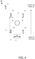
- FIG. 4 illustrates an example process by which the arrayed speaker controller 26 is pre-configured to modify an incoming command signal 27 to produce a driver signal 25 for each of the speakers 16 that achieves the desired flat driver field.
- the process entails placing four test microphones 50-1, 50-2, 50-3, and 50-4 (generally, 50), spaced apart, within the environment 10 surrounding the expected head region 52 of the occupant.
- the locations of the test microphones 50 approximately define a two-dimensional noise cancellation zone 54 within which to produce the desired flat driver field.
- the microphones 50-1 and 50-3 together correspond to a position of the head of the occupant turned 45 degrees to the right
- the microphones 50-2 and 50-4 together correspond to a position of the head of the occupant turned 45 degrees to the left.
- An optimization routine measures a frequency response from the input of the arrayed speaker controller 26 to each of the microphones 50.
- the objective of the optimization routine is to find a transformation (e.g., gain and delay) to be applied to the driver signals 25 such that the frequency response (in magnitude and phase) from the input of the arrayed speaker controller 26 to all of the test microphones 50 is substantially the same. Accordingly, the perceptible effect of noise cancellation becomes the same throughout the noise cancellation zone 54.
- the optimization routine computes the set of driver signals 25 by using a fixed gain for one of the three speakers (e.g., 16-1) and three free parameters for the other two speakers (e.g., 16-2, 16-3).
- the three free parameters correspond to the two gains for each of the other two speakers (e.g., 16-2, 16-3) and a delay for one of the other two speakers (e.g., 16-2, 16-3).
- One example solution produced by the optimization routine applies a fixed gain of 1 to the command signal 27 to produce the driver signal 25 sent to the left speaker 16-1, a gain of approximately -1 and a delay to produce the driver signal 25 sent to the center speaker 16-2, and a gain of 1 to produce the driver signal 25 sent to the right speaker 16-3.
- the optimization routine takes into account the physical displacement of the center speaker 16-2.
- the side speakers 16-1, 16-3 operate in phase; accordingly, the outputs of the side speakers 16-1, 16-3 sum.
- the center speaker 16-2 acts individually. Having the center speaker 16-2 closer to the head of the occupant than the side speakers 16-1, 16-3 has a flattening effect on the driver field.
- the arrayed speaker controller 26 is preconfigured with the solution produced by the optimization routine, to be used during operation of the noise cancellation system 12 to produce the driver signals 25 based on the command signal 27 received from the compensator 24.
- optimization routine can use other parameters instead of, or in addition to, gain and delays, examples of which include, but are not limited to, linear and non-linear filters, pole frequencies, and zero frequencies.
- FIG. 5 shows an example of a process 100 for configuring the noise cancellation system 12 with parameter values to be applied to the command signal 27 to produce the driver signals 25 used to drive the speakers 16 in order to cancel noise at the head of an occupant of an area, for example, within the cabin of a vehicle.
- the process 100 includes defining (step 102) a two-dimensional noise cancellation zone 54 to be occupied by a prospective occupant and within which to produce a desired flat driver field. To define this zone, at least three test microphones 50 are placed in front of the speakers 16, spatially separated to produce a two-dimensional area (e.g., an isolateral triangle, a rectangle, a parallelogram). The locations of the three speakers 16 preferably correspond to the expected locations of the speakers during the operation of the noise cancellation system 12.
- the speakers 16 emit (step 104) sound having a range of frequencies of interest (i.e., the original form of this audio signal is predetermined).
- the design of the noise cancellation system 12 can be to attenuate low-frequency noises (5-150 Hz), and the audio signal contains frequencies that span a desired frequency range.
- a transfer function i.e., its magnitude and phase response
- the optimization routine adjusts (step 108) certain parameters of the arrayed speaker controller 26 driving the speakers 16, to converge on a set of parameter values that produce approximately the same frequency response, in magnitude and phase, across the desired frequency range, from the speakers 16 to all of the test microphones 50.
- the solution arrived at by the optimization routine achieves generation, by the speakers, of a substantially flat driver field that closely matches a substantially flat noise field within the cancellation zone.
- the arrayed speaker controller 26 is configured (step 110) with the parameter values (e.g., gains and delay) arrived at by the optimization routine for use driving the speakers 16 during the operational stage.
- FIG. 6 shows an example of a process 150 for providing noise cancellation within the noise cancellation zone 54 defined as described in connection with FIG. 5 .
- the process 150 reference is made to the elements of FIG. 1 .
- at least one system microphone 18, disposed near the area to be occupied detects (step 152) sound, which may include frequency components deemed noise.
- each microphone 18 produces (step 154) a signal.
- the compensator 24 of the system controller 22 executes (step 156) an algorithm that generates a command signal 27.
- An objective of the algorithm is to achieve a noticeable reduction (e.g., at least 4 dB) at the occupant's ears.
- the executed algorithm applies one or more filters to the signal produced by each system microphone 18.
- the executed algorithm can apply a different filter to the signal produced by each microphone 18, and combine the results to produce the command signal.
- An applied filter can be digital or analog, linear or non-linear.
- the arrayed speaker controller 26 of the system controller 22 receives the command signal 27 and produces (step 158) a set of driver signals in response to the command signal 27.
- Each driver signal 25 is associated with a different one of the speakers 16.
- the arrayed speaker controller 26 sends the driver signals 25 to the amplifier 20.
- the amplifier 20 drives (step 160) each speaker 16 in accordance with the driver signal associated with that speaker.
- the sound emitted by the speakers 16 together produces a substantially flat sound pressure field inverse (i.e., approximately equal in magnitude and out-of-phase by 180 degrees) to the substantially flat noise field corresponding to the noise detected by the at least one system microphone 18.
- FIG. 7 shows an example of a noise cancellation system 12' adapted to transition back and forth between arrayed and in-phase speaker configurations.
- the noise cancellation system 12' includes a system controller 22' in communication with an amplifier 20.
- the amplifier 20 is in communication with the plurality of speakers 16-1, 16-2, and 16-3, positioned as described in connection with FIG. 1 .
- the system controller 22' includes the compensator 24 in communication with a switch 170 (also considered a signal director module).
- the compensator 24 produces a command signal 27 based on one or more signals 23 received from one or more system microphones 18.
- the switch 170 is in communication with the arrayed speaker controller 26 and an in-phase speaker controller 172. In a first state, the switch 170 passes the command signal 27 received from the compensator 24 to the arrayed speaker controller 26 in its entirety; the in-phase speaker controller 172 does not receive any portion of the command signal 27. In a second state, the switch 170 passes the command signal 27 in its entirety to the in-phase speaker controller 172; the arrayed speaker controller 26 does not receive any portion of the command signal 27.
- the arrayed speaker controller 26 In response to receiving the command signal 27, the arrayed speaker controller 26 produces individual driver signals 25 for each of the speakers 16, as described previously in connection with FIG. 1 , in order to produce a flat sound pressure field.
- the amplifier 20 receives the driver signals 25 and drives each speaker in accordance with the driver signal 25 for that speaker.
- An example of the gains 174-1 applied to the driver signals 25 to produce a flat sound pressure field include a gain of 1 for the left speaker 16-1, a gain of -1 for the center speaker 16-2 (and a delay), and a gain of 1 for the right speaker 16-3. The net sum of these gains equals one speaker (1 + (-1) + 1).
- Cancellation of noise events with large pressure amplitudes requires equally large pressures from the speakers 16; the relatively low pressure response of arrayed speakers to driver voltages results in clipping when the amplifier output voltage reaches its limit. Because the arrayed configuration mode may overdrive the amplifier, the noise cancellation system 12' transitions to the in-phase configuration mode when those certain noise-related events occur. Driving the three speakers 16-1, 16-2, 16-3 in the in-phase configuration mode increases the acoustic gain by a factor of three. Accordingly, the amplifier 20 requires less output voltage to drive the speakers 16 to achieve the noise-cancelling output intended by the compensator 24 when the speakers are the in-phase configuration mode than in the arrayed configuration mode.
- the in-phase speaker controller 172 In response to the command signal 27, the in-phase speaker controller 172 produces a common in-phase driver signal 175 to be sent to all of the speakers 16, with the in-phase speaker controller 172 applying a 1/3 gain for each speaker 16. Like the arrayed configuration mode, the net sum of the gains is one speaker (1/3 + 1/3 + 1/3), but the voltage required to achieve the noise-cancelling speaker output is one-third that required by the arrayed configuration mode. Accordingly, when operating in the in-phase configuration mode, the amplifier 20 does not clip. It is to be understood that the gains and the net sum of the gains produced by the arrayed speaker controller 26 and in-phase speaker controller 172 are example values provided to illustrate the principles.
- the system controller 22' further includes a signal magnitude monitor 176 coupled to the outputs of the arrayed speaker controller 26 and of the in-phase speaker controller 172, and to the switch 170.
- the signal magnitude monitor 176 causes the switch 170 to direct the command signal 27 to the in-phase speaker controller 172, in response to detecting a noise-related event that may cause the arrayed speaker controller 26 to overdrive the amplifier 20 and cause clipping.
- the signal magnitude monitor 176 monitors the output of the arrayed speaker controller 26, comparing the magnitude of the driver signals 25 with a threshold value, and initiates a transition from the arrayed configuration to the in-phase configuration when the magnitude exceeds the threshold.
- the signal magnitude monitor 176 causes the switch 170 to transition back to directing the entirety of the command signal 27 to the arrayed speaker controller 26.
- FIG. 8 is a block diagram of another example of a noise cancellation system 12" according to the invention adapted to transition between arrayed and in-phase speaker configurations in response to a noise-related event in order to avoid overdriving an amplifier.
- the noise cancellation system 12" includes a system controller 22" configured to cancel noise in two noise cancellation zones 54-1, 54-2.
- the components for canceling noise in the noise cancellation zone 54-2 are shown in phantom to signify such features are optional, and that the principles described in connection with FIG. 8 apply to noise cancellation in just a single noise cancellation zone.
- the noise cancellation system 12" proportions the command signal 27 between the arrayed and in-phase speaker configuration modes, instead of proportioning the command signal 27 in its entirety to one configuration mode or the other as described in FIG. 7 .
- the system controller 22" is in communication with a first amplifier 20-1 and, optionally, a second amplifier 20-2. Each amplifier 20-1, 20-2 is in communication with a set of speakers 16A, 16B, respectively.
- the system controller 22" includes a compensator 24 in communication with a first signal divider 180-1 and, optionally, with a second signal divider 180-2.
- the compensator 24 produces a command signal 27-1 based on one or more signals 23 received from one or more system microphones 18 (not shown) associated with the first zone 54-1 and, optionally, a command signal 27-2 based on one or more signals 23 received from one or more system microphones 18 (not shown) associated with the second noise cancellation zone 54-2.
- the command signal 27-1 passes to the signal divider 180-1, and, optionally, the command signal 27-2 passes to the signal divider 180-2.
- the signal divider 180-1 includes a bandwidth modulated filter that extracts an arrayed speaker signal 183-1 from the command signal 27, and passes the arrayed speaker signal 183-1 to the arrayed speaker controller 26-1 and the cut-off frequency of the high-pass filter is modulated by the output of the signal director module 188.
- the signal divider 180-1 can use the high-pass filter to pass the higher frequencies of the command signal 27 to the arrayed speaker controller 26-1.
- the signal divider 180-1 creates complementary high-pass and low-pass filters for sending the higher frequencies to the arrayed speaker controller 26-1 and the lower frequencies to the in-phase speaker controller 172-1.
- the signal divider 180-1 can have other implementations, such as a frequency independent gain adjustment, where a certain percentage of the signal is sent to the arrayed speaker controller 26-1 and the rest is sent to the in-phase speaker controller 172-1.
- the arrayed speaker controller 26-1 applies the preconfigured parameter values to the arrayed speaker signal 183-1 to generate a set of driver signals 25 (one for each speaker) designed to produce a flat driver field, as described in FIG. 1 .
- the signal divider 180-1 also produces an in-phase speaker signal 185-1 from the command signal 27-1.
- the in-phase speaker controller 172-1 applies a 1/3 gain to the in-phase speaker signal 185-1 to produce an in-phase driver signal 175 for each speaker 16 (the same driver signal 175), as described in FIG. 7 .
- An adder 184-1 combines the set of driver signals 25 from the arrayed speaker controller 26-1 with the in-phase driver signal 175, producing a hybrid command signal 187 for each speaker 16.
- the connectivity among, and operation of, the components that cancel noise in the second noise cancellation zone 54-2, namely, the signal divider 180-2, adder 184-2, the arrayed speaker controller 26-2, and in-phase array controller 172-2, are similar to their counterparts involved in canceling noise in the first noise cancellation zone 54-1.
- the system controller 22" further includes a signal magnitude monitor 186 in communication with a signal director module 188.
- the signal magnitude monitor 186 computes a magnitude based on the hybrid command signals 187-1 being passed to the amplifier 20-1, and, optionally, also on the hybrid command signals 187-2 being passed to the amplifier 20-2.
- the signal magnitude monitor 186 squares the magnitude of the hybrid command signals 187-1.
- the signal magnitude monitor 186 computes the magnitude by multiplying the magnitude of the hybrid command signals 187-1 by the magnitude of the hybrid command signals 187-2. The computed magnitude passes to the signal director module 188.
- the signal director module 188 determines which portion of the command signal 27-1 passes to the arrayed speaker controller 26-1 and which portion of the command signal 27-1 passes to the in-phase speaker controller 172-1. In general, as the computed magnitude approaches the limits of the amplifier to drive the speakers without clipping, a greater portion of the command signal is directed to the in-phase speaker controller.
- the signal director module 188 can use the computed magnitude to adjust the corner frequency, for example, used by the signal divider 180-1 to proportion the command signal between the arrayed and in-phase configuration modes.
- the corner frequency can be reduced to 0 Hz; conversely, to direct the entirety of the command signal to the in-phase speaker controller 172-1, the corner frequency can be raised to the maximum value for the signal divider 180-1 (e.g., 200 Hz). Accordingly, the signal director module 188 implements a "sliding scale" to determine which range of frequencies of the command signal 27-1 pass to the in-phase speaker controller 172-1 and which range of frequencies passes to the arrayed speaker controller 26-1.
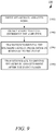
- FIG. 9 shows an example process 190 for transitioning between arrayed and in-phase speaker configuration modes.
- the system controller 22' or 22
- the system controller 22' or 22
- the signal magnitude monitor 176 may determine that the magnitude of the driver signals 25 exceeds a threshold corresponding to the limit of the amplifier 20 to drive the speakers without clipping.
- this noise-related event detection corresponds to the signal director module 188 of the noise cancellation system 12" of FIG. 8 receiving an increased computed magnitude value from the signal magnitude monitor 186.
- the system controller adjusts (step 196) the speaker configuration mode in real time. For example, in the noise cancellation system 12' of FIG. 7 , the system controller 22' switches to driving all speakers in the in-phase configuration mode in response to the detected noise event. According to the invention, in the noise cancellation system 12" of FIG. 8 , the system controller 22" increases the proportion of the command signal being sent to the in-phase speaker controller 172-1, while conversely decreasing the proportion of the command signal passing to the arrayed speaker controller 26-1.
- the system controller transitions back (step 198) to driving the speakers in the arrayed configuration mode.
- the system controller 22' switches back to driving all speakers in the arrayed configuration mode after the magnitude of the in-phase driver signal 175 falls below a threshold (or after a predetermined period elapses).
- the system controller 22" can reduce the proportion of the command signal passed to the in-phase speaker controller, while, conversely, increasing the proportion of the command signal passing to the arrayed speaker controller, in real time, in response to a decreased magnitude value computed by the signal magnitude monitor.
- the transfer function from the command signal to the system microphone for in-phase speaker configuration closely matches (in phase and magnitude) the transfer function for the arrayed speaker configuration at low frequencies (between 0 -350 Hz).
- This close matching effectively hides from the compensator 24 (i.e., the generator of the command signal) the proportioning of the command signal between the in-phase and arrayed speaker controllers.
- the transfer function to the system microphone is effectively the same; the system controller effectively sees the same plant.
- an adjustment module e.g., a linear or non-linear filter
- an adjustment module can be placed before the array speaker controller, before the in-phase speaker controller, or before both, to ensure the proportion change does not so detrimentally alter the transfer function.
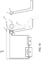
- FIG. 10 shows an example of an environment 10' in which a noise cancellation system can be deployed.
- the plurality of speakers 16 may be disposed behind the head of the occupant 200 within the environment 10', for example, mounted on a headrest, headliner, rear panel, or other interior surface of a vehicle.
- Other example locations for the speakers may be in the headliner 202 and on the rear-facing side of a headrest 204, provided such speakers are arrayed, as described herein.
- One system microphone 18 can be disposed, for example, on the unit 30 containing the speakers 16; another system microphone 18 (shown in phantom) may be disposed in the headliner 202.
- the amplifier 20 and system controller 22 (having the compensator, arrayed speaker controller, in-phase speaker controller, etc.) may be disposed, for example, in the trunk of the vehicle.
- the controller 22 is in electrical communication with the one or more system microphones 18 to receive the signal produced by each system microphone.
- Examples of the systems and methods described above comprise computer components and computer-implemented steps that will be apparent to those skilled in the art.
- the computer-implemented steps may be stored as computer-executable instructions on a computer-readable medium such as, for example, floppy disks, hard disks, optical disks, Flash ROMS, nonvolatile ROM, and RAM.
Landscapes
- Physics & Mathematics (AREA)
- Engineering & Computer Science (AREA)
- Acoustics & Sound (AREA)
- Multimedia (AREA)
- Health & Medical Sciences (AREA)
- General Health & Medical Sciences (AREA)
- Otolaryngology (AREA)
- Signal Processing (AREA)
- Soundproofing, Sound Blocking, And Sound Damping (AREA)
- Fittings On The Vehicle Exterior For Carrying Loads, And Devices For Holding Or Mounting Articles (AREA)
- Circuit For Audible Band Transducer (AREA)
- Obtaining Desirable Characteristics In Audible-Bandwidth Transducers (AREA)
Description
- This specification relates generally to noise cancellation systems, and, more specifically, to noise attenuation or cancellation (referred to generally as noise cancellation) within a specific environment, such as a passenger compartment of a vehicle.
US2015/063583 A1 ,US 2008/304677 A1 andUS 2014/233748 A1 relates to methods and systems for active noise cancellation. - According to a first aspect of the present invention, there is provided a noise cancellation system as defined in appended
claim 1. According to a second aspect of the present invention, there is provided a method of attenuating noise as defined in appended claim 5. - The above and further features and advantages may be better understood by referring to the following description in conjunction with the accompanying drawings, in which like numerals indicate like structural elements and features in various figures. The drawings are not necessarily to scale, emphasis instead being placed upon illustrating the principles of features and implementations.
-
FIG. 1 is a diagram of an environment having an example noise cancellation system, that does not form part of the invention, installed therein. -
FIG. 2 is a graph illustrating a substantially uniform sound pressure field generated by three arrayed speakers. -
FIG. 3 is a graph illustrating a decreasing sound pressure field generated by three speakers driven in phase with the same command signal. -
FIG. 4 is a diagram illustrating an example process for determining driver signals to drive arrayed speakers. -
FIG. 5 is a flow diagram illustrating an example process for configuring the noise cancellation system to drive arrayed speakers in order to produce a substantially uniform sound pressure field. -
FIG. 6 is a flow diagram of an example process for cancelling noise. -
FIG. 7 is a block diagram of an example noise cancellation system, that does not form part of the invention, that switches between arrayed and in-phase speaker configurations. -
FIG. 8 is a block diagram of a noise cancellation system according to the invention that blends arrayed and in-phase speaker configurations depending upon noise-related events. -
FIG. 9 is a flow diagram of an example process for switching between arrayed and in-phase speaker configurations. -
FIG. 10 is a diagram illustrating deployment of a noise cancellation system within an environment relative to an occupant. - Conventional noise cancellation systems generally use feedback from a microphone picking up noise to control a speaker such that the sound from the speaker cancels the noise at the microphone. Applicant recognized a mismatch existed between the noise field in which the occupant was immersed and the driver field produced by the speaker. Whereas the noise field was generally spatially flat (i.e., the sound pressure field or spectral density was relatively constant around the head of the occupant), the driver field decreased rapidly from the speaker location, similarly to a 1/r (1/radius) response. Noise cancellation occurred at the line of intersection of the noise field and driver field, which amounted to a small region near the ears of the occupant. Outside of that region, the noise cancellation system could produce a disagreeable sensation whenever the occupant turned her head sideways to one side or the other.
- Active noise cancellation systems described herein increase the area of a noise cancellation zone around the head of the occupant in comparison to such above-noted noise cancellation systems by producing a sound pressure field that closely matches the noise field in magnitude but with inverted phase over a relatively large spatial region. Each active noise cancellation zone includes at least one system microphone and a plurality of speakers. In general, a system microphone measures pressure at a point and feeds that measurement to a controller. In one example configuration, the speakers are arrayed. As used herein, "arrayed speakers" refers to a specific relationship among the speakers that has been pre-determined, in terms of magnitude and phase, such that the speakers together produce a substantially spatially flat sound pressure field. In addition, as used herein, a uniform driver field or a uniform noise field refers to a field with a power spectrum that does not vary substantially, spatially, across a given area. (The power spectrum may vary spectrally while being uniform spatially). One skilled in the art will recognize that a perfectly uniform sound pressure field rarely occurs in practice; some variations in amplitude are expected across the zone; hence, the driver field and noise field may be referred to as being substantially or approximately uniform or substantially or approximately flat.
- In one example configuration, the plurality of speakers includes three speakers disposed within a vehicle headrest and arranged in a row: one speaker at the left-hand side of the headrest, one speaker in the center, and one on the right-hand side of the headrest. Each system microphone measures sound near or within the noise cancellation zone and provides a signal to a system controller. The system controller drives the speakers, which are arrayed to produce a substantially uniform (i.e., flat) driver field that closely matches the noise field in magnitude with the opposite phase within the cancellation zone. The matching of the driver field to the noise field increases the breadth and length of the noise cancellation zone around the head of the occupant by increasing the extent of the intersection region between the noise field and driver field.
- Driving the speakers in an arrayed configuration generally produces satisfactory noise cancellation for an occupant whose head is within the cancellation zone. However, to achieve the flat driver field, some of the output from one speaker cancels the output of the others, making the arrayed system less efficient as a result. Satisfactory results notwithstanding, applicant recognized certain noise-related events, for example, driving a vehicle over a crack or a tar strip in the road, could cause the system controller to produce a high output (voltage) that resulted in audible amplifier clipping. To avoid the audible clipping, some examples of noise cancellation systems transition from driving the speakers in an arrayed configuration mode to an in-phase configuration mode, which has no cancellation between speakers and is, therefore, efficient relative to the arrayed configuration mode, in real-time response to detection of a certain noise-related event. As used herein, speakers driven in a "in phase" configuration mode means that all of the speakers are being driven with the same command signal. Because driving the speakers in the in-phase configuration mode has a smaller zone of noise cancellation than the arrayed configuration mode, the transition is momentary to avoid audible artifacts, and the noise cancellation system can transition back to the arrayed configuration mode in real-time after the certain noise-generating event ceases.
-
FIG. 1 shows a generalized example of anenvironment 10 having anoise cancellation system 12, that does not form part of the invention, installed therein for attenuating or canceling noise within the environment. The principles described herein apply to feed-forward and feedback noise cancellation systems. The noise cancellation techniques described herein can extend to a variety of specific environments, whether such environments are open or enclosed. For example, the deployment of thenoise cancellation system 12 can be in vehicles (e.g., automobiles, trucks, buses, trains, airplanes, boats, and vessels), living rooms, movie theatres, auditoriums; in general, anywhere the strategic placement of arrayed speakers can achieve noise cancellation for the occupants of such environments, as described below. In vehicles, for example, thenoise cancellation system 12 can serve to attenuate low frequency (e.g., 40 Hz - 200 Hz) road noise, advantageously reducing any need to add weight to certain regions of the vehicle for this purpose. - In the example shown, the
noise cancellation system 12 includes a plurality of speakers 16-1, 16-2, 16-3 (in general, speaker 16), one ormore microphones 18, anamplifier 20, and asystem controller 22. Thesystem controller 22 is in communication with the one ormore system microphones 18 to receivesignals 23 therefrom and with theamplifier 20 to senddriver signals 25 thereto in response to the signals. Theamplifier 20 is in communication with the plurality ofspeakers 16 to drive eachspeaker 16 in accordance with thedriver signals 25. - In this example, the
speakers 16 are arrayed. Thearrayed speakers 16 may be incorporated together in asingle unit 30, for example, in a headrest of a vehicle (e.g., facing the occupant from behind the occupant's head), or distributed apart (e.g., in a ring of speakers around the occupant), or some together and others apart (e.g., two speakers on the forward-facing side of a headrest, and another speaker on the rear-facing side of another headrest in front of the occupant). All speakers may be on the same plane (horizontal or vertical), that is, an imaginary plane passes through the center of all speakers. - In one example configuration, the plurality of
speakers 16 has three speakers 16-1, 16-2, 16-3. All of thespeakers 16 are disposed behind the head of an occupant; thespeakers 16 face forward towards the occupant and are on the same imaginary horizontal plane. The speaker 16-1 on the left is spatially aligned with the speaker 16-3 on the right (they are equidistant from the forward facing side of the unit 30). The speaker 16-2 is displaced by a predetermined distance, being closer to the forward facing side of theunit 30 than the speakers 16-1, 16-3 on opposite sides of the speaker 16-2. With theunit 30 behind the head of the occupant, the center speaker 16-2 is closer to the head than the other two outside speakers 16-1, 16-3. The center speaker 16-2 is closer to the head because simulations show this arrangement producing a more uniform pressure field than having allspeakers 16 arranged in a row. - The one or
more system microphones 18 are disposed within theenvironment 10 to be occupied by an individual. Eachsystem microphone 18 can detects sound in the listening area and, in response, produce a signal. In response to the signal, thesystem controller 22 produces a command signal that is sent to the arrayed speakers. The arrayed speakers are designed such that the acoustic transfer function from the speakers to thesystem microphone 18 matches the acoustic transfer function measured from the speakers to various points within the desired noise cancellation zone. In general, an acoustic transfer function corresponds to a measured response at a given location to a source of sound (e.g., a speaker) at another location. This measured response captures the relationship between the output (i.e., the sound detected at a given location) and the input (i.e., driver voltage). The measured relationship is a function of frequency and has magnitude and phase components. - In one example configuration, each
microphone 18 is located within theenvironment 10 where the acoustic transfer function for sound radiating from the plurality ofspeakers 16 to the location of thatmicrophone 18 is substantially equal to the acoustic transfer function for the sound from the plurality ofspeakers 16 to an ear of the occupant. An example technique for identifying such locations for microphones is described inU.S. application no. 14/449,325, filed August 1, 2014 - The
system controller 22, which may be embodied in theamplifier 20, includes acompensator 24 in communication with an arrayedspeaker controller 26. Thecompensator 24 produces acommand signal 27 based on the one ormore signals 23 received from the one ormore system microphones 18. - In general, the arrayed
speaker controller 26 uses thecommand signal 27 received from thecompensator 24 to producedriver signals 25 adapted to produce a spatially flat driver field. Thecompensator 24, when computing thecommand signal 27, does not account for the operation of the arrayedspeaker controller 26; the algorithm executed by thecompensator 24 produces thecommand signal 27 irrespective of whether the speakers are configured as arrayed or in-phase. Based on thecommand signal 27, the arrayedspeaker controller 26 produces aseparate driver signal 25 for eachspeaker 16 of the plurality of speakers. The driver signals 25 are tailored to drive thespeakers 16 such that thespeakers 16 produce a spatially flat driver field of a particular magnitude and phase to cancel the noise field. The arrayedspeaker controller 26 sends these driver signals 25 to theamplifier 20 to drive thespeakers 16 accordingly. -
FIG. 2 shows a three-dimensional graph 35 of an example of a substantially uniform (flat)sound pressure field 40 that may be produced by the arrayedspeakers 16 driven with equal amplitude voltages. Sound pressure magnitude in dB (referenced to an arbitrary pressure) is measured on the vertical axis (z-axis) and distance (in inches) is measured on the x- and y-axes. Fourvertical lines 42 correspond to temporary locations of four test microphones, used to define thefield 40 for which a substantially constant (i.e., uniform) sound pressure magnitude is desired, as described in more detail in connection withFIG. 4 . The test microphones do not remain in these positions when thenoise cancellation system 12 is operating. The approximate positions of the speakers 16-1, 16-2, and 16-3 coincide generally with the three major peaks in thegraph 35. From each of these peaks, the sound pressure magnitude drops precipitously and levels off at the substantially flatsound pressure field 40. In this example, the x- and y-dimensions of the flatsound pressure field 40 are approximately 4.5 inches by 4.5 inches, and starts immediately in front at the center speaker 16-2. The flatsound pressure field 40, which is designed to intersect and cancel the substantially flat noise field, corresponds to the noise cancellation zone. -
FIG. 3 shows a three-dimensional graph 45 of an example of asound pressure field 48 that may be produced by thespeakers 16 driven in-phase with equal amplitude voltages. Similar toFIG. 2 , sound pressure magnitude in dB (referenced to an arbitrary pressure) is measured on the vertical axis (z-axis) and distance (in inches) is measured on the x- and y-axes. The fourvertical lines 42, corresponding to the temporary locations of the four test microphones, are shown only to provide reference points for comparing thegraph 35 ofFIG. 2 with thegraph 45. The approximate positions of the speakers 16-1, 16-2, and 16-3 are also shown. From peak levels at these speaker locations, the sound pressure magnitude decreases steadily with increasing distance from the speakers. Driving thespeakers 16 in an in-phase configuration is generally sub-optimal because thesound pressure field 48 is sloped relative to a generally flat noise field, and thus produces a relatively small region of cancellation (i.e., along a line where the noise field and the driver field intersect) in comparison to the intersection region produced by the flatsound pressure field 40 ofFIG. 2 . Notwithstanding, an in-phase configuration can provide a higher response than an arrayed configuration for the same driver voltage. -
FIG. 4 illustrates an example process by which the arrayedspeaker controller 26 is pre-configured to modify anincoming command signal 27 to produce adriver signal 25 for each of thespeakers 16 that achieves the desired flat driver field. The process entails placing four test microphones 50-1, 50-2, 50-3, and 50-4 (generally, 50), spaced apart, within theenvironment 10 surrounding the expectedhead region 52 of the occupant. The locations of the test microphones 50 approximately define a two-dimensionalnoise cancellation zone 54 within which to produce the desired flat driver field. The microphones 50-1 and 50-3 together correspond to a position of the head of the occupant turned 45 degrees to the right, and the microphones 50-2 and 50-4 together correspond to a position of the head of the occupant turned 45 degrees to the left. - An optimization routine (algorithm) measures a frequency response from the input of the arrayed
speaker controller 26 to each of the microphones 50. The objective of the optimization routine is to find a transformation (e.g., gain and delay) to be applied to the driver signals 25 such that the frequency response (in magnitude and phase) from the input of the arrayedspeaker controller 26 to all of the test microphones 50 is substantially the same. Accordingly, the perceptible effect of noise cancellation becomes the same throughout thenoise cancellation zone 54. - In one example implementation, the optimization routine computes the set of driver signals 25 by using a fixed gain for one of the three speakers (e.g., 16-1) and three free parameters for the other two speakers (e.g., 16-2, 16-3). The three free parameters correspond to the two gains for each of the other two speakers (e.g., 16-2, 16-3) and a delay for one of the other two speakers (e.g., 16-2, 16-3). One example solution produced by the optimization routine applies a fixed gain of 1 to the
command signal 27 to produce thedriver signal 25 sent to the left speaker 16-1, a gain of approximately -1 and a delay to produce thedriver signal 25 sent to the center speaker 16-2, and a gain of 1 to produce thedriver signal 25 sent to the right speaker 16-3. The optimization routine takes into account the physical displacement of the center speaker 16-2. The side speakers 16-1, 16-3 operate in phase; accordingly, the outputs of the side speakers 16-1, 16-3 sum. The center speaker 16-2 acts individually. Having the center speaker 16-2 closer to the head of the occupant than the side speakers 16-1, 16-3 has a flattening effect on the driver field. The arrayedspeaker controller 26 is preconfigured with the solution produced by the optimization routine, to be used during operation of thenoise cancellation system 12 to produce the driver signals 25 based on thecommand signal 27 received from thecompensator 24. - It is to be understood that the optimization routine can use other parameters instead of, or in addition to, gain and delays, examples of which include, but are not limited to, linear and non-linear filters, pole frequencies, and zero frequencies.
-
FIG. 5 shows an example of aprocess 100 for configuring thenoise cancellation system 12 with parameter values to be applied to thecommand signal 27 to produce the driver signals 25 used to drive thespeakers 16 in order to cancel noise at the head of an occupant of an area, for example, within the cabin of a vehicle. In the description of theprocess 100, reference is made to the elements ofFIG. 1 . Theprocess 100 includes defining (step 102) a two-dimensionalnoise cancellation zone 54 to be occupied by a prospective occupant and within which to produce a desired flat driver field. To define this zone, at least three test microphones 50 are placed in front of thespeakers 16, spatially separated to produce a two-dimensional area (e.g., an isolateral triangle, a rectangle, a parallelogram). The locations of the threespeakers 16 preferably correspond to the expected locations of the speakers during the operation of thenoise cancellation system 12. - The
speakers 16 emit (step 104) sound having a range of frequencies of interest (i.e., the original form of this audio signal is predetermined). For example, the design of thenoise cancellation system 12 can be to attenuate low-frequency noises (5-150 Hz), and the audio signal contains frequencies that span a desired frequency range. A transfer function (i.e., its magnitude and phase response) is measured (step 106) from the input of theamplifier 20 to each of the test microphones 50. The optimization routine adjusts (step 108) certain parameters of the arrayedspeaker controller 26 driving thespeakers 16, to converge on a set of parameter values that produce approximately the same frequency response, in magnitude and phase, across the desired frequency range, from thespeakers 16 to all of the test microphones 50. The solution arrived at by the optimization routine achieves generation, by the speakers, of a substantially flat driver field that closely matches a substantially flat noise field within the cancellation zone. The arrayedspeaker controller 26 is configured (step 110) with the parameter values (e.g., gains and delay) arrived at by the optimization routine for use driving thespeakers 16 during the operational stage. -
FIG. 6 shows an example of aprocess 150 for providing noise cancellation within thenoise cancellation zone 54 defined as described in connection withFIG. 5 . In the description of theprocess 150, reference is made to the elements ofFIG. 1 . During operation of thenoise cancellation system 12, at least onesystem microphone 18, disposed near the area to be occupied, detects (step 152) sound, which may include frequency components deemed noise. In response to the sound, eachmicrophone 18 produces (step 154) a signal. - In response to the signal (or signals) from the at least one
system microphone 18, thecompensator 24 of thesystem controller 22 executes (step 156) an algorithm that generates acommand signal 27. An objective of the algorithm is to achieve a noticeable reduction (e.g., at least 4 dB) at the occupant's ears. In general, the executed algorithm applies one or more filters to the signal produced by eachsystem microphone 18. In the instance ofmultiple microphones 18, the executed algorithm can apply a different filter to the signal produced by eachmicrophone 18, and combine the results to produce the command signal. An applied filter can be digital or analog, linear or non-linear. - The arrayed
speaker controller 26 of thesystem controller 22 receives thecommand signal 27 and produces (step 158) a set of driver signals in response to thecommand signal 27. Eachdriver signal 25 is associated with a different one of thespeakers 16. With arrayed speakers, at least two of the speakers receive different driver signals 25 (e.g., different gain, delay, or both); typically, all of the speakers receive adifferent driver signal 25. The arrayedspeaker controller 26 sends the driver signals 25 to theamplifier 20. Theamplifier 20 drives (step 160) eachspeaker 16 in accordance with the driver signal associated with that speaker. The sound emitted by thespeakers 16 together produces a substantially flat sound pressure field inverse (i.e., approximately equal in magnitude and out-of-phase by 180 degrees) to the substantially flat noise field corresponding to the noise detected by the at least onesystem microphone 18. - The following example shown in
FIG. 7 does not correspond to the claimed invention and is simply presented for illustration purposes.FIG. 7 shows an example of a noise cancellation system 12' adapted to transition back and forth between arrayed and in-phase speaker configurations. The noise cancellation system 12' includes a system controller 22' in communication with anamplifier 20. Theamplifier 20 is in communication with the plurality of speakers 16-1, 16-2, and 16-3, positioned as described in connection withFIG. 1 . - The system controller 22' includes the
compensator 24 in communication with a switch 170 (also considered a signal director module). Thecompensator 24 produces acommand signal 27 based on one ormore signals 23 received from one ormore system microphones 18. Theswitch 170 is in communication with the arrayedspeaker controller 26 and an in-phase speaker controller 172. In a first state, theswitch 170 passes thecommand signal 27 received from thecompensator 24 to the arrayedspeaker controller 26 in its entirety; the in-phase speaker controller 172 does not receive any portion of thecommand signal 27. In a second state, theswitch 170 passes thecommand signal 27 in its entirety to the in-phase speaker controller 172; the arrayedspeaker controller 26 does not receive any portion of thecommand signal 27. - In response to receiving the
command signal 27, the arrayedspeaker controller 26 produces individual driver signals 25 for each of thespeakers 16, as described previously in connection withFIG. 1 , in order to produce a flat sound pressure field. Theamplifier 20 receives the driver signals 25 and drives each speaker in accordance with thedriver signal 25 for that speaker. - An example of the gains 174-1 applied to the driver signals 25 to produce a flat sound pressure field include a gain of 1 for the left speaker 16-1, a gain of -1 for the center speaker 16-2 (and a delay), and a gain of 1 for the right speaker 16-3. The net sum of these gains equals one speaker (1 + (-1) + 1).
- Cancellation of noise events with large pressure amplitudes requires equally large pressures from the
speakers 16; the relatively low pressure response of arrayed speakers to driver voltages results in clipping when the amplifier output voltage reaches its limit. Because the arrayed configuration mode may overdrive the amplifier, the noise cancellation system 12' transitions to the in-phase configuration mode when those certain noise-related events occur. Driving the three speakers 16-1, 16-2, 16-3 in the in-phase configuration mode increases the acoustic gain by a factor of three. Accordingly, theamplifier 20 requires less output voltage to drive thespeakers 16 to achieve the noise-cancelling output intended by thecompensator 24 when the speakers are the in-phase configuration mode than in the arrayed configuration mode. In response to thecommand signal 27, the in-phase speaker controller 172 produces a common in-phase driver signal 175 to be sent to all of thespeakers 16, with the in-phase speaker controller 172 applying a 1/3 gain for eachspeaker 16. Like the arrayed configuration mode, the net sum of the gains is one speaker (1/3 + 1/3 + 1/3), but the voltage required to achieve the noise-cancelling speaker output is one-third that required by the arrayed configuration mode. Accordingly, when operating in the in-phase configuration mode, theamplifier 20 does not clip. It is to be understood that the gains and the net sum of the gains produced by the arrayedspeaker controller 26 and in-phase speaker controller 172 are example values provided to illustrate the principles. - The system controller 22' further includes a signal magnitude monitor 176 coupled to the outputs of the arrayed
speaker controller 26 and of the in-phase speaker controller 172, and to theswitch 170. The signal magnitude monitor 176 causes theswitch 170 to direct thecommand signal 27 to the in-phase speaker controller 172, in response to detecting a noise-related event that may cause the arrayedspeaker controller 26 to overdrive theamplifier 20 and cause clipping. The signal magnitude monitor 176 monitors the output of the arrayedspeaker controller 26, comparing the magnitude of the driver signals 25 with a threshold value, and initiates a transition from the arrayed configuration to the in-phase configuration when the magnitude exceeds the threshold. In response to the passage of a predetermined period, or to the monitored output of the in-phase speaker controller 172 falling below a predetermined threshold value, the signal magnitude monitor 176 causes theswitch 170 to transition back to directing the entirety of thecommand signal 27 to the arrayedspeaker controller 26. -
FIG. 8 is a block diagram of another example of anoise cancellation system 12" according to the invention adapted to transition between arrayed and in-phase speaker configurations in response to a noise-related event in order to avoid overdriving an amplifier. Thenoise cancellation system 12" includes asystem controller 22" configured to cancel noise in two noise cancellation zones 54-1, 54-2. The components for canceling noise in the noise cancellation zone 54-2 are shown in phantom to signify such features are optional, and that the principles described in connection withFIG. 8 apply to noise cancellation in just a single noise cancellation zone. In general, thenoise cancellation system 12" proportions thecommand signal 27 between the arrayed and in-phase speaker configuration modes, instead of proportioning thecommand signal 27 in its entirety to one configuration mode or the other as described inFIG. 7 . - The
system controller 22" is in communication with a first amplifier 20-1 and, optionally, a second amplifier 20-2. Each amplifier 20-1, 20-2 is in communication with a set ofspeakers system controller 22" includes acompensator 24 in communication with a first signal divider 180-1 and, optionally, with a second signal divider 180-2. Thecompensator 24 produces a command signal 27-1 based on one ormore signals 23 received from one or more system microphones 18 (not shown) associated with the first zone 54-1 and, optionally, a command signal 27-2 based on one ormore signals 23 received from one or more system microphones 18 (not shown) associated with the second noise cancellation zone 54-2. The command signal 27-1 passes to the signal divider 180-1, and, optionally, the command signal 27-2 passes to the signal divider 180-2. - In one example implementation, the signal divider 180-1 includes a bandwidth modulated filter that extracts an arrayed speaker signal 183-1 from the
command signal 27, and passes the arrayed speaker signal 183-1 to the arrayed speaker controller 26-1 and the cut-off frequency of the high-pass filter is modulated by the output of thesignal director module 188. The signal divider 180-1 can use the high-pass filter to pass the higher frequencies of thecommand signal 27 to the arrayed speaker controller 26-1. The signal divider 180-1 creates complementary high-pass and low-pass filters for sending the higher frequencies to the arrayed speaker controller 26-1 and the lower frequencies to the in-phase speaker controller 172-1. The signal divider 180-1 can have other implementations, such as a frequency independent gain adjustment, where a certain percentage of the signal is sent to the arrayed speaker controller 26-1 and the rest is sent to the in-phase speaker controller 172-1. - The arrayed speaker controller 26-1 applies the preconfigured parameter values to the arrayed speaker signal 183-1 to generate a set of driver signals 25 (one for each speaker) designed to produce a flat driver field, as described in
FIG. 1 . - The signal divider 180-1 also produces an in-phase speaker signal 185-1 from the command signal 27-1. The in-phase speaker controller 172-1 applies a 1/3 gain to the in-phase speaker signal 185-1 to produce an in-
phase driver signal 175 for each speaker 16 (the same driver signal 175), as described inFIG. 7 . - An adder 184-1 combines the set of driver signals 25 from the arrayed speaker controller 26-1 with the in-
phase driver signal 175, producing ahybrid command signal 187 for eachspeaker 16. - The connectivity among, and operation of, the components that cancel noise in the second noise cancellation zone 54-2, namely, the signal divider 180-2, adder 184-2, the arrayed speaker controller 26-2, and in-phase array controller 172-2, are similar to their counterparts involved in canceling noise in the first noise cancellation zone 54-1.
- The
system controller 22" further includes a signal magnitude monitor 186 in communication with asignal director module 188. In communication with the output of the adder 184-1 and, optionally, with the output of the adder 184-2, the signal magnitude monitor 186 computes a magnitude based on the hybrid command signals 187-1 being passed to the amplifier 20-1, and, optionally, also on the hybrid command signals 187-2 being passed to the amplifier 20-2. In one example implementation, the signal magnitude monitor 186 squares the magnitude of the hybrid command signals 187-1. In another example implementation, the signal magnitude monitor 186 computes the magnitude by multiplying the magnitude of the hybrid command signals 187-1 by the magnitude of the hybrid command signals 187-2. The computed magnitude passes to thesignal director module 188. - In response to the computed magnitude, the
signal director module 188 determines which portion of the command signal 27-1 passes to the arrayed speaker controller 26-1 and which portion of the command signal 27-1 passes to the in-phase speaker controller 172-1. In general, as the computed magnitude approaches the limits of the amplifier to drive the speakers without clipping, a greater portion of the command signal is directed to the in-phase speaker controller. Thesignal director module 188 can use the computed magnitude to adjust the corner frequency, for example, used by the signal divider 180-1 to proportion the command signal between the arrayed and in-phase configuration modes. For example, to direct the whole command signal to the arrayed speaker controller 26-1, the corner frequency can be reduced to 0 Hz; conversely, to direct the entirety of the command signal to the in-phase speaker controller 172-1, the corner frequency can be raised to the maximum value for the signal divider 180-1 (e.g., 200 Hz). Accordingly, thesignal director module 188 implements a "sliding scale" to determine which range of frequencies of the command signal 27-1 pass to the in-phase speaker controller 172-1 and which range of frequencies passes to the arrayed speaker controller 26-1. -
FIG. 9 shows anexample process 190 for transitioning between arrayed and in-phase speaker configuration modes. In the description of theprocess 190, reference is made to the elements ofFIG. 7 for illustration purposes only. The process according to the invention is described with reference to the elements ofFIG. 8 . Consider, as a convenient starting point to describe theprocess 190, that the system controller (22' or 22") is driving (step 192) a set of speakers in an arrayed configuration mode. A certain noise-related event is detected (step 194). In the noise cancellation system 12' ofFIG. 7 , the signal magnitude monitor 176 may determine that the magnitude of the driver signals 25 exceeds a threshold corresponding to the limit of theamplifier 20 to drive the speakers without clipping. According to the invention, this noise-related event detection corresponds to thesignal director module 188 of thenoise cancellation system 12" ofFIG. 8 receiving an increased computed magnitude value from the signal magnitude monitor 186. - In response to the detecting of the noise-related event, the system controller adjusts (step 196) the speaker configuration mode in real time. For example, in the noise cancellation system 12' of
FIG. 7 , the system controller 22' switches to driving all speakers in the in-phase configuration mode in response to the detected noise event. According to the invention, in thenoise cancellation system 12" ofFIG. 8 , thesystem controller 22" increases the proportion of the command signal being sent to the in-phase speaker controller 172-1, while conversely decreasing the proportion of the command signal passing to the arrayed speaker controller 26-1. - After the noise-related event ends, the system controller transitions back (step 198) to driving the speakers in the arrayed configuration mode. For example, in the noise cancellation system 12' of
FIG. 7 , the system controller 22' switches back to driving all speakers in the arrayed configuration mode after the magnitude of the in-phase driver signal 175 falls below a threshold (or after a predetermined period elapses). According to the invention, in thenoise cancellation system 12" ofFIG. 8 , thesystem controller 22" can reduce the proportion of the command signal passed to the in-phase speaker controller, while, conversely, increasing the proportion of the command signal passing to the arrayed speaker controller, in real time, in response to a decreased magnitude value computed by the signal magnitude monitor. - In general, the transfer function from the command signal to the system microphone for in-phase speaker configuration closely matches (in phase and magnitude) the transfer function for the arrayed speaker configuration at low frequencies (between 0 -350 Hz). This close matching effectively hides from the compensator 24 (i.e., the generator of the command signal) the proportioning of the command signal between the in-phase and arrayed speaker controllers. Irrespective of the particular division of the command signal between the in-phase speaker controller and the arrayed speaker controller, the transfer function to the system microphone is effectively the same; the system controller effectively sees the same plant.
- In implementations where changing the proportion of the command signal allotted to arrayed speaker controller and that allotted to the in-phase speaker controller alters the transfer function (i.e., to the effect the system controller now sees a different plant), an adjustment module (e.g., a linear or non-linear filter) can be placed before the array speaker controller, before the in-phase speaker controller, or before both, to ensure the proportion change does not so detrimentally alter the transfer function.
-
FIG. 10 shows an example of an environment 10' in which a noise cancellation system can be deployed. In this example, the plurality of speakers 16 (only one shown) may be disposed behind the head of theoccupant 200 within the environment 10', for example, mounted on a headrest, headliner, rear panel, or other interior surface of a vehicle. Other example locations for the speakers may be in theheadliner 202 and on the rear-facing side of aheadrest 204, provided such speakers are arrayed, as described herein. - One
system microphone 18 can be disposed, for example, on theunit 30 containing thespeakers 16; another system microphone 18 (shown in phantom) may be disposed in theheadliner 202. Theamplifier 20 and system controller 22 (having the compensator, arrayed speaker controller, in-phase speaker controller, etc.) may be disposed, for example, in the trunk of the vehicle. Thecontroller 22 is in electrical communication with the one ormore system microphones 18 to receive the signal produced by each system microphone. - Examples of the systems and methods described above comprise computer components and computer-implemented steps that will be apparent to those skilled in the art. For example, it should be understood by one of skill in the art that the computer-implemented steps may be stored as computer-executable instructions on a computer-readable medium such as, for example, floppy disks, hard disks, optical disks, Flash ROMS, nonvolatile ROM, and RAM.
- Furthermore, it should be understood by one of skill in the art that the computer-executable instructions may be executed on a variety of processors such as, for example, microprocessors, digital signal processors, gate arrays, etc. For ease of exposition, not every step or element of the systems and methods described above is described herein as part of a computer system, but those skilled in the art will recognize that each step or element may have a corresponding computer system or software component.
Claims (10)
- A noise cancellation system (12") comprising:three or more speakers (16) disposed within an area;an amplifier (20) in communication with the three or more speakers (16); anda system controller (22") in communication with at least one microphone (18) disposed within the area and the amplifier (20), the system controller comprising:a compensator (24) in communication with a signal divider (180) and with the at least one microphone (18), the compensator producing a command signal (27) in response to a signal (23) from the at least one microphone produced in response to sound detected within the area, the command signal being configured to attenuate a noise field in a particular zone within the area in response to the signal from the at least one microphone; an arrayed speaker controller (26), in communication with the signal divider (180), configured to receive an arrayed speaker signal (183) from the signal divider (180) and to apply gain and/or delay, based on predetermined parameter values, to the arrayed speaker signal to produce at least two different individual driver signals (25) for each of the three or more speakers (16);an in-phase speaker controller (172), in communication with the signal divider (181), configured to receive an in-phase speaker signal (185) from the signal divider (180) and to apply a same gain to the in-phase speaker signal to produce a common in-phase driver signal (175) for each of the three or more speakers (16);an adder (184) in connection with the arrayed speaker controller (26) and the in-phase speaker controller (172) and with the amplifier (20), the adder being configured to combine the individual driver signals (25) and the in-phase driver signal (175) to produce a hybrid command signal (187) for each of the three or more speakers,wherein the amplifier drives each of the three or more speakers according to the hybrid command signal to produce a flat sound pressure field for the particular zone within the area, the flat sound pressure field produced by the three or more speakers having a magnitude equal to the noise field detected by the at least one microphone and a phase shifted by 180 degreescharacterized in that:the system controller further comprises a signal magnitude monitor (186) in communication with a signal director module (188) and with the adder (184), the signal magnitude monitor being configured to compute a magnitude based on the hybrid command signals (187) being passed to the amplifier and to transmit it to the signal director module, the signal director module being configured to determine, based on the received computed magnitude, which portion of the command signal passes to the arrayed speaker controller and which portion to the in-phase speaker controller,and that the signal divider (180) is in communication with the compensator (24) and with the arrayed speaker controller (26) and the in-phase speaker controller (172), the signal divider being configured to extract the arrayed speaker signal (183) from the command signal and to pass it to the arrayed speaker controller, and to extract the in-phase speaker signal (185) from the command signal and to pass it to the in-phase speaker controller.
- The noise cancellation system of claim 1, wherein the three or more speakers are arranged along a common plane.
- The noise cancellation system of claim 1, wherein the three or more speakers include a left speaker, a center speaker, and a right speaker, the particular zone surrounds an expected location of a head of an occupant of the area, the left and right speakers are disposed an equal distance from the expected location of the head of the occupant, and the center speaker is closer to the expected location of the head of the occupant than the left and right speakers.
- The noise cancellation system of claim 1, wherein a sum of the gains for the driver signals is approximately equal to one.
- A method of attenuating noise comprising:producing a command signal (27) configured to attenuate a noise field in a particular zone within an area in response to a signal from at least one microphone disposed within the area;extracting an arrayed speaker signal (183) and an in-phase speaker signal (185) from the command signal;transmitting the arrayed speaker signal (183) to an arrayed speaker controller (26) and the in-phase speaker signal (185) to an in-phase speaker controller (172);producing in response to receiving the arrayed speaker signal (183) at least two different individual driver signals (25) for each of the three or more speakers by applying gain and/or delay based on predetermined parameter values to the arrayed speaker signal;producing in response to receiving the in-phase speaker signal (185) a common in-phase driver signal (175) for each of the three or more speakers by applying a same gain to the in-phase speaker signal;producing a hybrid command signal (187) for each of the three or more speakers by combining the individual driver signals and the in-phase driver signal; andgenerating within the particular zone in the area, by combined sound emitted by the three or more speakers in response to the hybrid command signal (187), a sound pressure field having a magnitude equal to the noise field detected by the at least one microphone and a phase shifted by 180 degreescharacterized in that:the method further comprises monitoring the hybrid command signals and computing a magnitude based on the monitored hybrid command signals; anddetermining based on the computed magnitude which portion of the command signal is extracted as the arrayed speaker signal and which portion is extracted as the in-phase speaker signal.
- The method of claim 5, further comprising arranging the three or more speakers along a common plane.
- The method of claim 5, wherein the three or more speakers include a left speaker, a center speaker, and a right speaker, the particular zone surrounds an expected location of a head of an occupant of the area, the left and right speakers are disposed an equal distance from the expected location of the head of the occupant, and the center speaker is closer to the expected location of the head of the occupant than the left and right speakers.
- The method of claim 5, wherein a sum of the gains for the driver signals is approximately equal to one.
- The method of claim 5, wherein one of the individual driver signals includes a delay.
- A vehicle comprising:a passenger compartment; anda noise cancellation system according to any of claims 1 to 4, the noise cancellation system being configured to attenuate a noise field in an area within the passenger compartment.
Applications Claiming Priority (2)
| Application Number | Priority Date | Filing Date | Title |
|---|---|---|---|
| US14/749,801 US9640169B2 (en) | 2015-06-25 | 2015-06-25 | Arraying speakers for a uniform driver field |
| PCT/US2016/038893 WO2016210049A1 (en) | 2015-06-25 | 2016-06-23 | Noise cancellation system arraying speakers for a uniform driver field |
Publications (2)
| Publication Number | Publication Date |
|---|---|
| EP3314909A1 EP3314909A1 (en) | 2018-05-02 |
| EP3314909B1 true EP3314909B1 (en) | 2021-02-17 |
Family
ID=56297144
Family Applications (1)
| Application Number | Title | Priority Date | Filing Date |
|---|---|---|---|
| EP16734135.3A Active EP3314909B1 (en) | 2015-06-25 | 2016-06-23 | Noise cancellation system arraying speakers for a uniform driver field |
Country Status (5)
| Country | Link |
|---|---|
| US (3) | US9640169B2 (en) |
| EP (1) | EP3314909B1 (en) |
| JP (1) | JP6644093B2 (en) |
| CN (1) | CN107710785B (en) |
| WO (1) | WO2016210049A1 (en) |
Families Citing this family (19)
| Publication number | Priority date | Publication date | Assignee | Title |
|---|---|---|---|---|
| US9303715B2 (en) | 2013-03-10 | 2016-04-05 | Oshkosh Defense, Llc | Limiting system for a vehicle suspension component |
| US12491943B1 (en) | 2013-03-10 | 2025-12-09 | Oshkosh Defense, Llc | Systems and methods for a military vehicle |
| EP3528240A4 (en) * | 2016-10-17 | 2019-11-27 | Sony Corporation | SIGNAL PROCESSING DEVICE, METHOD AND PROGRAM |
| CA3058160A1 (en) * | 2017-03-30 | 2018-10-04 | Magic Leap, Inc. | Non-blocking dual driver earphones |
| US10796682B2 (en) * | 2017-07-11 | 2020-10-06 | Ford Global Technologies, Llc | Quiet zone for handsfree microphone |
| US20190037363A1 (en) * | 2017-07-31 | 2019-01-31 | GM Global Technology Operations LLC | Vehicle based acoustic zoning system for smartphones |
| CN107644634A (en) * | 2017-08-01 | 2018-01-30 | 柴世军 | Environmental audio denoising device |
| WO2019139925A1 (en) * | 2018-01-09 | 2019-07-18 | Dolby Laboratories Licensing Corporation | Reducing unwanted sound transmission |
| WO2019222208A1 (en) | 2018-05-18 | 2019-11-21 | Oshkosh Corporation | In-seat sound suppression |
| CN108847209A (en) * | 2018-06-01 | 2018-11-20 | 会听声学科技(北京)有限公司 | A kind of denoising device and noise-reduction method |
| US11381915B2 (en) * | 2018-11-26 | 2022-07-05 | Lg Electronics Inc. | Vehicle and operation method thereof |
| US11545126B2 (en) * | 2019-01-17 | 2023-01-03 | Gulfstream Aerospace Corporation | Arrangements and methods for enhanced communication on aircraft |
| US10904686B2 (en) * | 2019-03-29 | 2021-01-26 | Mitsubishi Heavy Industries, Ltd. | Method of acoustic tuning in aircraft cabin |
| CN113811945B (en) * | 2019-04-01 | 2024-01-26 | 伯斯有限公司 | Noise cancellation signal saturation control |
| CN110740407B (en) * | 2019-10-24 | 2020-11-24 | 安徽大学 | An active noise reduction method for train bearing trackside acoustic signals based on dual microphones |
| US11170752B1 (en) * | 2020-04-29 | 2021-11-09 | Gulfstream Aerospace Corporation | Phased array speaker and microphone system for cockpit communication |
| CN111516576A (en) * | 2020-04-30 | 2020-08-11 | 歌尔科技有限公司 | Automobile headrest and automobile sound system |
| US11691552B2 (en) | 2020-10-05 | 2023-07-04 | Lear Corporation | Vehicle seats that include sound cancelation systems |
| US12104985B2 (en) * | 2021-04-19 | 2024-10-01 | Acoustic Research Systems, Llc | System for aerospace acoustic testing |
Citations (1)
| Publication number | Priority date | Publication date | Assignee | Title |
|---|---|---|---|---|
| US20140233748A1 (en) * | 2013-02-15 | 2014-08-21 | Dennis Klug | Forward Speaker Noise Cancellation In a Vehicle |
Family Cites Families (39)
| Publication number | Priority date | Publication date | Assignee | Title |
|---|---|---|---|---|
| JPS5857193A (en) * | 1981-09-30 | 1983-04-05 | 日野自動車株式会社 | Noise reducing apparatus for inside of vehicle |
| US4503553A (en) | 1983-06-03 | 1985-03-05 | Dbx, Inc. | Loudspeaker system |
| US5133017A (en) | 1990-04-09 | 1992-07-21 | Active Noise And Vibration Technologies, Inc. | Noise suppression system |
| JP3053026B2 (en) * | 1991-07-02 | 2000-06-19 | パイオニア株式会社 | Speaker device |
| US7062049B1 (en) | 1999-03-09 | 2006-06-13 | Honda Giken Kogyo Kabushiki Kaisha | Active noise control system |
| US7450725B2 (en) | 2001-12-17 | 2008-11-11 | Mahle International Gmbh | Digital filter modeling for active noise cancellation |
| JP4131108B2 (en) * | 2002-02-28 | 2008-08-13 | ソニー株式会社 | Seat system and external noise canceling device usable therefor |
| US20040208325A1 (en) | 2003-04-15 | 2004-10-21 | Cheung Kwok Wai | Method and apparatus for wireless audio delivery |
| CA2522896A1 (en) | 2003-04-23 | 2004-11-04 | Rh Lyon Corp | Method and apparatus for sound transduction with minimal interference from background noise and minimal local acoustic radiation |
| WO2006051602A1 (en) | 2004-11-12 | 2006-05-18 | Takenaka Corporation | Noise reduction apparatus |
| JP4701944B2 (en) * | 2005-09-14 | 2011-06-15 | ヤマハ株式会社 | Sound field control equipment |
| JP4311402B2 (en) * | 2005-12-21 | 2009-08-12 | ヤマハ株式会社 | Loudspeaker system |
| US7356603B2 (en) | 2006-03-29 | 2008-04-08 | Rauland - Borg Corporation | Integrated system of loads with multiple public awareness functions |
| JP4722878B2 (en) * | 2007-04-19 | 2011-07-13 | ソニー株式会社 | Noise reduction device and sound reproduction device |
| US20080304677A1 (en) | 2007-06-08 | 2008-12-11 | Sonitus Medical Inc. | System and method for noise cancellation with motion tracking capability |
| US8355512B2 (en) | 2008-10-20 | 2013-01-15 | Bose Corporation | Active noise reduction adaptive filter leakage adjusting |
| US8135140B2 (en) * | 2008-11-20 | 2012-03-13 | Harman International Industries, Incorporated | System for active noise control with audio signal compensation |
| JP5177012B2 (en) * | 2009-02-25 | 2013-04-03 | 富士通株式会社 | Noise suppression device, noise suppression method, and computer program |
| US8891781B2 (en) * | 2009-04-15 | 2014-11-18 | Pioneer Corporation | Active vibration noise control device |
| US8045725B2 (en) | 2009-04-16 | 2011-10-25 | GM Global Technology Operations LLC | Vehicle interior active noise cancellation |
| US8077873B2 (en) | 2009-05-14 | 2011-12-13 | Harman International Industries, Incorporated | System for active noise control with adaptive speaker selection |
| WO2010150368A1 (en) * | 2009-06-24 | 2010-12-29 | パイオニア株式会社 | Acoustic field regulator |
| US8340312B2 (en) | 2009-08-04 | 2012-12-25 | Apple Inc. | Differential mode noise cancellation with active real-time control for microphone-speaker combinations used in two way audio communications |
| EP2288178B1 (en) * | 2009-08-17 | 2012-06-06 | Nxp B.V. | A device for and a method of processing audio data |
| US8649533B2 (en) * | 2009-10-02 | 2014-02-11 | Ford Global Technologies, Llc | Emotive advisory system acoustic environment |
| JP2011121534A (en) | 2009-12-14 | 2011-06-23 | Honda Motor Co Ltd | Active noise control device |
| US8737634B2 (en) * | 2011-03-18 | 2014-05-27 | The United States Of America As Represented By The Secretary Of The Navy | Wide area noise cancellation system and method |
| WO2012153294A2 (en) | 2011-05-11 | 2012-11-15 | Silentium Ltd. | Device, system and method of noise control |
| JP5326056B2 (en) | 2011-05-19 | 2013-10-30 | 東海ゴム工業株式会社 | Active silencer |
| FR2983335B1 (en) * | 2011-11-25 | 2019-11-08 | Renault S.A.S. | METHOD AND DEVICE FOR CONTROLLING AN ACTIVE NOISE REDUCTION SYSTEM |
| JP5728378B2 (en) * | 2011-12-26 | 2015-06-03 | 株式会社竹中工務店 | Noise reduction device |
| US9082389B2 (en) | 2012-03-30 | 2015-07-14 | Apple Inc. | Pre-shaping series filter for active noise cancellation adaptive filter |
| US8971561B2 (en) | 2012-06-20 | 2015-03-03 | Apple Inc. | Earphone having a controlled acoustic leak port |
| US20150003626A1 (en) | 2013-02-25 | 2015-01-01 | Max Sound Corporation | Active noise cancellation method for automobiles |
| US9257113B2 (en) | 2013-08-27 | 2016-02-09 | Texas Instruments Incorporated | Method and system for active noise cancellation |
| JP6111955B2 (en) * | 2013-09-27 | 2017-04-12 | アンデン株式会社 | Vehicle approach notification device |
| WO2015092943A1 (en) * | 2013-12-17 | 2015-06-25 | Sony Corporation | Electronic devices and methods for compensating for environmental noise in text-to-speech applications |
| US20160100250A1 (en) | 2014-10-02 | 2016-04-07 | AISIN Technical Center of America, Inc. | Noise-cancelation apparatus for a vehicle headrest |
| US9508336B1 (en) * | 2015-06-25 | 2016-11-29 | Bose Corporation | Transitioning between arrayed and in-phase speaker configurations for active noise reduction |
-
2015
- 2015-06-25 US US14/749,801 patent/US9640169B2/en active Active
-
2016
- 2016-06-23 JP JP2017566709A patent/JP6644093B2/en active Active
- 2016-06-23 EP EP16734135.3A patent/EP3314909B1/en active Active
- 2016-06-23 CN CN201680037387.5A patent/CN107710785B/en active Active
- 2016-06-23 WO PCT/US2016/038893 patent/WO2016210049A1/en not_active Ceased
-
2017
- 2017-03-22 US US15/465,968 patent/US10199030B2/en active Active
-
2018
- 2018-12-21 US US16/229,292 patent/US20190115006A1/en not_active Abandoned
Patent Citations (1)
| Publication number | Priority date | Publication date | Assignee | Title |
|---|---|---|---|---|
| US20140233748A1 (en) * | 2013-02-15 | 2014-08-21 | Dennis Klug | Forward Speaker Noise Cancellation In a Vehicle |
Also Published As
| Publication number | Publication date |
|---|---|
| US9640169B2 (en) | 2017-05-02 |
| US10199030B2 (en) | 2019-02-05 |
| JP2018518715A (en) | 2018-07-12 |
| US20170193977A1 (en) | 2017-07-06 |
| JP6644093B2 (en) | 2020-02-12 |
| US20160379618A1 (en) | 2016-12-29 |
| CN107710785A (en) | 2018-02-16 |
| US20190115006A1 (en) | 2019-04-18 |
| CN107710785B (en) | 2020-09-22 |
| EP3314909A1 (en) | 2018-05-02 |
| WO2016210049A1 (en) | 2016-12-29 |
Similar Documents
| Publication | Publication Date | Title |
|---|---|---|
| US10199030B2 (en) | Arraying speakers for a uniform driver field | |
| EP3314605B1 (en) | Transitioning between arrayed and in-phase speaker configurations for active noise reduction | |
| US9245519B2 (en) | Forward speaker noise cancellation in a vehicle | |
| US12293749B2 (en) | In-seat sound suppression | |
| EP3509320A1 (en) | Low frequency sound field in a listening environment | |
| JP2011205692A (en) | Indoor communication system for vehicular cabin | |
| EP2190221A1 (en) | Audio system | |
| EP3133831A1 (en) | System and method for in-car communication | |
| CN115299076A (en) | Loudspeaker system layout for generating low frequency audio output in independent sound zones | |
| JP6452377B2 (en) | Speaker arrangement selection device, speaker arrangement selection method, and sound field control system | |
| EP4052483B1 (en) | Loudspeaker arrangement | |
| Borroni et al. | Experimental analysis of individual listening zone algorithms in controlled environments | |
| KR102914649B1 (en) | Sound system for vehicle and sound output method using the system | |
| KR102911025B1 (en) | Sound system for vehicle and sound output method using the system | |
| GB2569113A (en) | Method and apparatus for controlling an audio output |
Legal Events
| Date | Code | Title | Description |
|---|---|---|---|
| STAA | Information on the status of an ep patent application or granted ep patent |
Free format text: STATUS: THE INTERNATIONAL PUBLICATION HAS BEEN MADE |
|
| PUAI | Public reference made under article 153(3) epc to a published international application that has entered the european phase |
Free format text: ORIGINAL CODE: 0009012 |
|
| STAA | Information on the status of an ep patent application or granted ep patent |
Free format text: STATUS: REQUEST FOR EXAMINATION WAS MADE |
|
| 17P | Request for examination filed |
Effective date: 20171218 |
|
| AK | Designated contracting states |
Kind code of ref document: A1 Designated state(s): AL AT BE BG CH CY CZ DE DK EE ES FI FR GB GR HR HU IE IS IT LI LT LU LV MC MK MT NL NO PL PT RO RS SE SI SK SM TR |
|
| AX | Request for extension of the european patent |
Extension state: BA ME |
|
| DAV | Request for validation of the european patent (deleted) | ||
| DAX | Request for extension of the european patent (deleted) | ||
| STAA | Information on the status of an ep patent application or granted ep patent |
Free format text: STATUS: EXAMINATION IS IN PROGRESS |
|
| 17Q | First examination report despatched |
Effective date: 20181220 |
|
| GRAP | Despatch of communication of intention to grant a patent |
Free format text: ORIGINAL CODE: EPIDOSNIGR1 |
|
| STAA | Information on the status of an ep patent application or granted ep patent |
Free format text: STATUS: GRANT OF PATENT IS INTENDED |
|
| RIC1 | Information provided on ipc code assigned before grant |
Ipc: H04R 1/40 20060101ALN20201119BHEP Ipc: H04R 3/12 20060101AFI20201119BHEP Ipc: G10K 11/178 20060101ALI20201119BHEP Ipc: H04R 1/02 20060101ALN20201119BHEP Ipc: H04S 7/00 20060101ALN20201119BHEP |
|
| INTG | Intention to grant announced |
Effective date: 20201203 |
|
| GRAS | Grant fee paid |
Free format text: ORIGINAL CODE: EPIDOSNIGR3 |
|
| GRAA | (expected) grant |
Free format text: ORIGINAL CODE: 0009210 |
|
| STAA | Information on the status of an ep patent application or granted ep patent |
Free format text: STATUS: THE PATENT HAS BEEN GRANTED |
|
| AK | Designated contracting states |
Kind code of ref document: B1 Designated state(s): AL AT BE BG CH CY CZ DE DK EE ES FI FR GB GR HR HU IE IS IT LI LT LU LV MC MK MT NL NO PL PT RO RS SE SI SK SM TR |
|
| REG | Reference to a national code |
Ref country code: GB Ref legal event code: FG4D |
|
| REG | Reference to a national code |
Ref country code: CH Ref legal event code: EP |
|
| REG | Reference to a national code |
Ref country code: DE Ref legal event code: R096 Ref document number: 602016052563 Country of ref document: DE |
|
| REG | Reference to a national code |
Ref country code: AT Ref legal event code: REF Ref document number: 1363090 Country of ref document: AT Kind code of ref document: T Effective date: 20210315 |
|
| REG | Reference to a national code |
Ref country code: IE Ref legal event code: FG4D |
|
| REG | Reference to a national code |
Ref country code: LT Ref legal event code: MG9D |
|
| REG | Reference to a national code |
Ref country code: NL Ref legal event code: MP Effective date: 20210217 |
|
| PG25 | Lapsed in a contracting state [announced via postgrant information from national office to epo] |
Ref country code: LT Free format text: LAPSE BECAUSE OF FAILURE TO SUBMIT A TRANSLATION OF THE DESCRIPTION OR TO PAY THE FEE WITHIN THE PRESCRIBED TIME-LIMIT Effective date: 20210217 Ref country code: BG Free format text: LAPSE BECAUSE OF FAILURE TO SUBMIT A TRANSLATION OF THE DESCRIPTION OR TO PAY THE FEE WITHIN THE PRESCRIBED TIME-LIMIT Effective date: 20210517 Ref country code: HR Free format text: LAPSE BECAUSE OF FAILURE TO SUBMIT A TRANSLATION OF THE DESCRIPTION OR TO PAY THE FEE WITHIN THE PRESCRIBED TIME-LIMIT Effective date: 20210217 Ref country code: FI Free format text: LAPSE BECAUSE OF FAILURE TO SUBMIT A TRANSLATION OF THE DESCRIPTION OR TO PAY THE FEE WITHIN THE PRESCRIBED TIME-LIMIT Effective date: 20210217 Ref country code: GR Free format text: LAPSE BECAUSE OF FAILURE TO SUBMIT A TRANSLATION OF THE DESCRIPTION OR TO PAY THE FEE WITHIN THE PRESCRIBED TIME-LIMIT Effective date: 20210518 Ref country code: PT Free format text: LAPSE BECAUSE OF FAILURE TO SUBMIT A TRANSLATION OF THE DESCRIPTION OR TO PAY THE FEE WITHIN THE PRESCRIBED TIME-LIMIT Effective date: 20210617 Ref country code: NO Free format text: LAPSE BECAUSE OF FAILURE TO SUBMIT A TRANSLATION OF THE DESCRIPTION OR TO PAY THE FEE WITHIN THE PRESCRIBED TIME-LIMIT Effective date: 20210517 |
|
| REG | Reference to a national code |
Ref country code: AT Ref legal event code: MK05 Ref document number: 1363090 Country of ref document: AT Kind code of ref document: T Effective date: 20210217 |
|
| PG25 | Lapsed in a contracting state [announced via postgrant information from national office to epo] |
Ref country code: SE Free format text: LAPSE BECAUSE OF FAILURE TO SUBMIT A TRANSLATION OF THE DESCRIPTION OR TO PAY THE FEE WITHIN THE PRESCRIBED TIME-LIMIT Effective date: 20210217 Ref country code: LV Free format text: LAPSE BECAUSE OF FAILURE TO SUBMIT A TRANSLATION OF THE DESCRIPTION OR TO PAY THE FEE WITHIN THE PRESCRIBED TIME-LIMIT Effective date: 20210217 Ref country code: NL Free format text: LAPSE BECAUSE OF FAILURE TO SUBMIT A TRANSLATION OF THE DESCRIPTION OR TO PAY THE FEE WITHIN THE PRESCRIBED TIME-LIMIT Effective date: 20210217 Ref country code: RS Free format text: LAPSE BECAUSE OF FAILURE TO SUBMIT A TRANSLATION OF THE DESCRIPTION OR TO PAY THE FEE WITHIN THE PRESCRIBED TIME-LIMIT Effective date: 20210217 Ref country code: PL Free format text: LAPSE BECAUSE OF FAILURE TO SUBMIT A TRANSLATION OF THE DESCRIPTION OR TO PAY THE FEE WITHIN THE PRESCRIBED TIME-LIMIT Effective date: 20210217 |
|
| PG25 | Lapsed in a contracting state [announced via postgrant information from national office to epo] |
Ref country code: IS Free format text: LAPSE BECAUSE OF FAILURE TO SUBMIT A TRANSLATION OF THE DESCRIPTION OR TO PAY THE FEE WITHIN THE PRESCRIBED TIME-LIMIT Effective date: 20210617 |
|
| PG25 | Lapsed in a contracting state [announced via postgrant information from national office to epo] |
Ref country code: EE Free format text: LAPSE BECAUSE OF FAILURE TO SUBMIT A TRANSLATION OF THE DESCRIPTION OR TO PAY THE FEE WITHIN THE PRESCRIBED TIME-LIMIT Effective date: 20210217 Ref country code: CZ Free format text: LAPSE BECAUSE OF FAILURE TO SUBMIT A TRANSLATION OF THE DESCRIPTION OR TO PAY THE FEE WITHIN THE PRESCRIBED TIME-LIMIT Effective date: 20210217 Ref country code: AT Free format text: LAPSE BECAUSE OF FAILURE TO SUBMIT A TRANSLATION OF THE DESCRIPTION OR TO PAY THE FEE WITHIN THE PRESCRIBED TIME-LIMIT Effective date: 20210217 Ref country code: SM Free format text: LAPSE BECAUSE OF FAILURE TO SUBMIT A TRANSLATION OF THE DESCRIPTION OR TO PAY THE FEE WITHIN THE PRESCRIBED TIME-LIMIT Effective date: 20210217 |
|
| REG | Reference to a national code |
Ref country code: DE Ref legal event code: R097 Ref document number: 602016052563 Country of ref document: DE |
|
| PG25 | Lapsed in a contracting state [announced via postgrant information from national office to epo] |
Ref country code: SK Free format text: LAPSE BECAUSE OF FAILURE TO SUBMIT A TRANSLATION OF THE DESCRIPTION OR TO PAY THE FEE WITHIN THE PRESCRIBED TIME-LIMIT Effective date: 20210217 Ref country code: RO Free format text: LAPSE BECAUSE OF FAILURE TO SUBMIT A TRANSLATION OF THE DESCRIPTION OR TO PAY THE FEE WITHIN THE PRESCRIBED TIME-LIMIT Effective date: 20210217 Ref country code: DK Free format text: LAPSE BECAUSE OF FAILURE TO SUBMIT A TRANSLATION OF THE DESCRIPTION OR TO PAY THE FEE WITHIN THE PRESCRIBED TIME-LIMIT Effective date: 20210217 |
|
| PLBE | No opposition filed within time limit |
Free format text: ORIGINAL CODE: 0009261 |
|
| STAA | Information on the status of an ep patent application or granted ep patent |
Free format text: STATUS: NO OPPOSITION FILED WITHIN TIME LIMIT |
|
| 26N | No opposition filed |
Effective date: 20211118 |
|
| PG25 | Lapsed in a contracting state [announced via postgrant information from national office to epo] |
Ref country code: MC Free format text: LAPSE BECAUSE OF FAILURE TO SUBMIT A TRANSLATION OF THE DESCRIPTION OR TO PAY THE FEE WITHIN THE PRESCRIBED TIME-LIMIT Effective date: 20210217 Ref country code: AL Free format text: LAPSE BECAUSE OF FAILURE TO SUBMIT A TRANSLATION OF THE DESCRIPTION OR TO PAY THE FEE WITHIN THE PRESCRIBED TIME-LIMIT Effective date: 20210217 Ref country code: ES Free format text: LAPSE BECAUSE OF FAILURE TO SUBMIT A TRANSLATION OF THE DESCRIPTION OR TO PAY THE FEE WITHIN THE PRESCRIBED TIME-LIMIT Effective date: 20210217 |
|
| REG | Reference to a national code |
Ref country code: CH Ref legal event code: PL |
|
| PG25 | Lapsed in a contracting state [announced via postgrant information from national office to epo] |
Ref country code: SI Free format text: LAPSE BECAUSE OF FAILURE TO SUBMIT A TRANSLATION OF THE DESCRIPTION OR TO PAY THE FEE WITHIN THE PRESCRIBED TIME-LIMIT Effective date: 20210217 |
|
| REG | Reference to a national code |
Ref country code: BE Ref legal event code: MM Effective date: 20210630 |
|
| PG25 | Lapsed in a contracting state [announced via postgrant information from national office to epo] |
Ref country code: LU Free format text: LAPSE BECAUSE OF NON-PAYMENT OF DUE FEES Effective date: 20210623 |
|
| PG25 | Lapsed in a contracting state [announced via postgrant information from national office to epo] |
Ref country code: LI Free format text: LAPSE BECAUSE OF NON-PAYMENT OF DUE FEES Effective date: 20210630 Ref country code: IT Free format text: LAPSE BECAUSE OF FAILURE TO SUBMIT A TRANSLATION OF THE DESCRIPTION OR TO PAY THE FEE WITHIN THE PRESCRIBED TIME-LIMIT Effective date: 20210217 Ref country code: IE Free format text: LAPSE BECAUSE OF NON-PAYMENT OF DUE FEES Effective date: 20210623 Ref country code: CH Free format text: LAPSE BECAUSE OF NON-PAYMENT OF DUE FEES Effective date: 20210630 |
|
| PG25 | Lapsed in a contracting state [announced via postgrant information from national office to epo] |
Ref country code: IS Free format text: LAPSE BECAUSE OF FAILURE TO SUBMIT A TRANSLATION OF THE DESCRIPTION OR TO PAY THE FEE WITHIN THE PRESCRIBED TIME-LIMIT Effective date: 20210617 |
|
| PG25 | Lapsed in a contracting state [announced via postgrant information from national office to epo] |
Ref country code: BE Free format text: LAPSE BECAUSE OF NON-PAYMENT OF DUE FEES Effective date: 20210630 |
|
| PG25 | Lapsed in a contracting state [announced via postgrant information from national office to epo] |
Ref country code: CY Free format text: LAPSE BECAUSE OF FAILURE TO SUBMIT A TRANSLATION OF THE DESCRIPTION OR TO PAY THE FEE WITHIN THE PRESCRIBED TIME-LIMIT Effective date: 20210217 |
|
| PG25 | Lapsed in a contracting state [announced via postgrant information from national office to epo] |
Ref country code: HU Free format text: LAPSE BECAUSE OF FAILURE TO SUBMIT A TRANSLATION OF THE DESCRIPTION OR TO PAY THE FEE WITHIN THE PRESCRIBED TIME-LIMIT; INVALID AB INITIO Effective date: 20160623 |
|
| PG25 | Lapsed in a contracting state [announced via postgrant information from national office to epo] |
Ref country code: MK Free format text: LAPSE BECAUSE OF FAILURE TO SUBMIT A TRANSLATION OF THE DESCRIPTION OR TO PAY THE FEE WITHIN THE PRESCRIBED TIME-LIMIT Effective date: 20210217 |
|
| PG25 | Lapsed in a contracting state [announced via postgrant information from national office to epo] |
Ref country code: MT Free format text: LAPSE BECAUSE OF FAILURE TO SUBMIT A TRANSLATION OF THE DESCRIPTION OR TO PAY THE FEE WITHIN THE PRESCRIBED TIME-LIMIT Effective date: 20210217 |
|
| PGFP | Annual fee paid to national office [announced via postgrant information from national office to epo] |
Ref country code: DE Payment date: 20250520 Year of fee payment: 10 |
|
| PGFP | Annual fee paid to national office [announced via postgrant information from national office to epo] |
Ref country code: GB Payment date: 20250520 Year of fee payment: 10 |
|
| PGFP | Annual fee paid to national office [announced via postgrant information from national office to epo] |
Ref country code: FR Payment date: 20250520 Year of fee payment: 10 |
|
| PG25 | Lapsed in a contracting state [announced via postgrant information from national office to epo] |
Ref country code: TR Free format text: LAPSE BECAUSE OF FAILURE TO SUBMIT A TRANSLATION OF THE DESCRIPTION OR TO PAY THE FEE WITHIN THE PRESCRIBED TIME-LIMIT Effective date: 20210217 |