EP3314414B1 - Asset-driven dynamically composed visualization system - Google Patents
Asset-driven dynamically composed visualization system Download PDFInfo
- Publication number
- EP3314414B1 EP3314414B1 EP16744958.6A EP16744958A EP3314414B1 EP 3314414 B1 EP3314414 B1 EP 3314414B1 EP 16744958 A EP16744958 A EP 16744958A EP 3314414 B1 EP3314414 B1 EP 3314414B1
- Authority
- EP
- European Patent Office
- Prior art keywords
- visualization
- child
- control
- template
- objects
- Prior art date
- Legal status (The legal status is an assumption and is not a legal conclusion. Google has not performed a legal analysis and makes no representation as to the accuracy of the status listed.)
- Revoked
Links
Images


Classifications
-
- G—PHYSICS
- G06—COMPUTING OR CALCULATING; COUNTING
- G06F—ELECTRIC DIGITAL DATA PROCESSING
- G06F3/00—Input arrangements for transferring data to be processed into a form capable of being handled by the computer; Output arrangements for transferring data from processing unit to output unit, e.g. interface arrangements
- G06F3/01—Input arrangements or combined input and output arrangements for interaction between user and computer
- G06F3/048—Interaction techniques based on graphical user interfaces [GUI]
- G06F3/0484—Interaction techniques based on graphical user interfaces [GUI] for the control of specific functions or operations, e.g. selecting or manipulating an object, an image or a displayed text element, setting a parameter value or selecting a range
- G06F3/04842—Selection of displayed objects or displayed text elements
-
- G—PHYSICS
- G05—CONTROLLING; REGULATING
- G05B—CONTROL OR REGULATING SYSTEMS IN GENERAL; FUNCTIONAL ELEMENTS OF SUCH SYSTEMS; MONITORING OR TESTING ARRANGEMENTS FOR SUCH SYSTEMS OR ELEMENTS
- G05B19/00—Program-control systems
- G05B19/02—Program-control systems electric
- G05B19/04—Program control other than numerical control, i.e. in sequence controllers or logic controllers
- G05B19/042—Program control other than numerical control, i.e. in sequence controllers or logic controllers using digital processors
-
- G—PHYSICS
- G06—COMPUTING OR CALCULATING; COUNTING
- G06F—ELECTRIC DIGITAL DATA PROCESSING
- G06F3/00—Input arrangements for transferring data to be processed into a form capable of being handled by the computer; Output arrangements for transferring data from processing unit to output unit, e.g. interface arrangements
- G06F3/01—Input arrangements or combined input and output arrangements for interaction between user and computer
- G06F3/048—Interaction techniques based on graphical user interfaces [GUI]
- G06F3/0481—Interaction techniques based on graphical user interfaces [GUI] based on specific properties of the displayed interaction object or a metaphor-based environment, e.g. interaction with desktop elements like windows or icons, or assisted by a cursor's changing behaviour or appearance
- G06F3/0482—Interaction with lists of selectable items, e.g. menus
-
- G—PHYSICS
- G06—COMPUTING OR CALCULATING; COUNTING
- G06F—ELECTRIC DIGITAL DATA PROCESSING
- G06F8/00—Arrangements for software engineering
- G06F8/30—Creation or generation of source code
- G06F8/38—Creation or generation of source code for implementing user interfaces
-
- G—PHYSICS
- G05—CONTROLLING; REGULATING
- G05B—CONTROL OR REGULATING SYSTEMS IN GENERAL; FUNCTIONAL ELEMENTS OF SUCH SYSTEMS; MONITORING OR TESTING ARRANGEMENTS FOR SUCH SYSTEMS OR ELEMENTS
- G05B2219/00—Program-control systems
- G05B2219/20—Pc systems
- G05B2219/23—Pc programming
- G05B2219/23258—GUI graphical user interface, icon, function bloc editor, labview
-
- G—PHYSICS
- G05—CONTROLLING; REGULATING
- G05B—CONTROL OR REGULATING SYSTEMS IN GENERAL; FUNCTIONAL ELEMENTS OF SUCH SYSTEMS; MONITORING OR TESTING ARRANGEMENTS FOR SUCH SYSTEMS OR ELEMENTS
- G05B2219/00—Program-control systems
- G05B2219/20—Pc systems
- G05B2219/25—Pc structure of the system
- G05B2219/25011—Domotique, I-O bus, home automation, building automation
-
- G—PHYSICS
- G06—COMPUTING OR CALCULATING; COUNTING
- G06F—ELECTRIC DIGITAL DATA PROCESSING
- G06F8/00—Arrangements for software engineering
- G06F8/30—Creation or generation of source code
- G06F8/36—Software reuse
Definitions
- the present disclosure relates generally to user interfaces and, more particularly, to systems and methods for dynamically created and configurable visualization interfaces for automation systems.
- Process monitoring and control relates to the viewing and control of parameters of one or more processes, environments in which the processes are performed, and/or the operation of equipment executing the processes.
- process parameters can include duration, temperature, pressure, speed, quantity, and/or direction of motion of a particular piece of machinery.
- the parameters can include to temperature of the operating environment, throughput (transactional and/or packet-based), downtime, usage, and similar quantities.
- Automation, or process control, systems can be used to help manage production, monitor and maintain equipment, view performance and operational trends, and/or perform business functions such as remotely modifying operational parameters, visual inspections, and maintenance scheduling.
- user interfaces in modern automation systems are exceedingly complex, and the configuration of such interfaces is generally a substantially time consuming and error-prone process. Accordingly, personnel who create, set up, and use such automation systems would benefit from enhanced techniques for generating and configuring visualization interfaces to reduce the required engineering work and increase the accuracy and efficiency of these processes.
- EP 2 728 427 (Rockwell, 2014 ) describes a design diagram representation for an industrial operator interface that illustrates state transitions, interlocks, and permissives for an industrial process as a state diagram, and renders live state information for the process as numeric indicators, string indicators, and color-animated state icons. Flow lines of the diagram are highlighted based on the displayed state information to convey an overall status of the process.
- a dynamic asset-driven visualization provides numerous possibilities for automatic composition of visualization displays at run-time, on-the-fly, based on the user request. Fast re-configuration of a production plant or other system allows an agile reorganization of assets, reduces the cost of reorganization, and better utilizes the resources of the system
- a computer-implemented method for creating an automation system visualization is disclosed.
- An application that includes a graphical user interface for constructing a visualization of an automation system.
- the automation system includes a plurality of objects that can be organized, for example, in a hierarchy.
- the application forms a visualization control that is a building block of the visualization of the automation system.
- the visualization control is associated with a first object in the plurality of objects.
- the first object which includes (i) a reference to a first visualization template and (ii) a plurality of properties associated with the first object, is received from an object storage.
- the referenced first visualization template is received from a template storage.
- the application then generates a visualization of the first object by mapping the properties associated with the first object to the visualization template, and assigns the visualization of the first object to the visualization control.
- the first visualization template can be a generic form of a type (e.g., location, sensor, control, etc.) of the first object, and can include a plurality of parameters to which one or more of the properties of the first object are mapped.
- the visualization control itself can include metadata defining its visual properties.
- An automation control data source can also be assigned to the visualization control.
- At least steps (c) through (e) are repeated for each child object in the first object.
- the application can form additional respective visualization controls for each child object in the first object, and place the additional visualization controls in the parent visualization control based on the first visualization template.
- the first object defines a location
- the child objects define automation system assets at the location.
- the visualization of the automation system can be made up of a plurality of visualization controls generated based on respective objects and templates.
- Described in various implementations herein are systems and methods for providing a visualization (e.g., a graphical representation and/or user interface) of an automation (process control) system, such as a manufacturing, industrial, energy, water treatment, or building (e.g., heating, air conditioning and ventilation) automation system, by dynamically generating and configuring the visualization from a system description stored in an asset (e.g., a software-based object) in combination with configuration template objects.
- an automation process control
- FIG. 1 depicts an exemplary automation system environment 100 for which an control interface can be generated and configured using various implementations of the present techniques.
- the environment 100 includes operational components that collect, analyze, present, and act on operational process control (OPC) data as it is generated and collected.
- OPC data is generated and collected at or more facilities 105a, 105b and 105c (generally, 105).
- facilities 105a, 105b and 105c generally, 105.
- three facilities 105 are shown for illustrative purposes only, as there can be any number of facilities 105, which can be part of a common processing or manufacturing facility, or geographically dispersed around the globe performing vastly different operations.
- process control equipment 110a, 110b and 110c can be installed to measure one or more processing parameters associated with the processes.
- a gauge can be placed inside a boiler to measure the temperature and/or pressure, or an optical scanner can be placed at the end of a manufacturing step to measure throughput or look for defects, and so on.
- the data from the individual pieces of process control equipment 110 can be collected for the entire facility and reported at a facility-specific OPC server 115a, 115b, and 115c for reporting and control purposes.
- the data collection and reporting may take place in real-time, asynchronously, or, in some cases, a combination of both.
- a centralized data collection and reporting system can consolidate, aggregate and/or compare data collected from each facility 105 and the various processes 110 operating at each facility 105.
- an enterprise OPC server 120 can communicate with the facility-specific OPC servers 115, the individual controllers 110 continuously or periodically using one or more data communications services.
- the enterprise OPC server 120 can in turn support client workstations 125a and 125b at which users can generate and configure user interfaces for viewing representations of the OPC data and, in some cases, for sending commands to manipulate processes and controls at each facility 105.
- Some or all of the components described above can be connected by and communicate via a network 130.
- the communication can take place via any media such as standard telephone lines, LAN or WAN links (e.g., T1, T3, 56 kb, X.25), broadband connections (ISDN, Frame Relay, ATM), wireless links, and so on.
- the network 130 can carry TCP/IP protocol communications, and HTTP/HTTPS requests made by a web browser and the connections among the controllers 110, the facility-specific OPC servers 115, the enterprise OPC server 120 and the client workstations 125 can be communicated over such TCP/IP networks.
- the type of network is not a limitation, however, and any suitable network can be used.
- Typical examples of networks that can serve as the communications network 130 include a wireless or wired Ethernet-based intranet, a local or wide-area network (LAN or WAN), and/or the internet, which can accommodate many different communications media and protocols.
- FIG. 2 illustrates an exemplary system 200 for collecting and reporting OPC data, including an application server 205, a data visualization server 210, and a configuration user interface 215 that each can operate in concert with one or more OPC servers.
- the system 200 can also include one or more data storage devices 220 for storing, among other things, configuration parameters that define the OPC servers, software-based objects and other data structures that define individual components in an automation system and their associated properties, and templates that are used in the configuration of automation system visualizations.
- Data storage device(s) 220 can include a non-transitory computer-readable storage medium, such as a hard disk drive, solid-state drive, random access memory, etc., and can store data in the form of a database, individual files, and so on.
- the application server 205 provides data collection, aggregation and transformation processing for the system.
- the application server 205 includes a communication stack 240 that allows the application server 205 to request and/or receive data from individual OPC servers 115, send data to the data visualization server 210 for charting and reporting, and the client workstations 125.
- the communications stack 240 includes a series of layered protocols for packaging and transmitting data among computers over a network.
- the communications stack provides TCP/IP-based communications among the system components to allow data to be sent via HTTP requests, XML/Web Services, and similar methods.
- the application server 205 also includes a unified data manager component 245 for manipulating data received from the various OPC servers 115.
- data is collected from processes and facilities with little or no defined relationship among the data elements.
- a shift supervisor can enter comments into an electronic log, and the comments receive timestamps and an operator ID.
- OPC devices can collect processing data such as throughput (e.g., pieces/hour) and quality measurements (e.g., defects/100 pieces), all of which are measured using different units (if any) and relating to different aspects of the facility.
- the unified data manager component 245 analyzes the incoming data and applies a rules-based algorithm to allow the data to be reported and charted using common units.
- the application server 205 also includes an OPC engine 250 for analyzing the OPC data as it is collected (either in real-time or asynchronously) and determining what subsequent processing, events and/or alarms are appropriate. For example, a set of rules can be defined such that the certain events (e.g., non-receipt of data, a data value outside a preferred range, etc.) warrant an alarm to be triggered and sent to a client workstation 125. In some instances the OPC engine 250 formats the data for presentation on reports and charts.
- the data visualization server 210 receives data from the application server 205 and presents it at the visualization server 210 and/or at one or more clients 125.
- the data can be presented in various forms, such as raw tabular form, text-based reports, graphical reports, and real-time graphical representations of the monitored processes enhanced with additional data (e.g., supply-chain data, inventory data, financial data, etc.), alarms, and visual indicators relating to the processes.
- a reporting engine 255 utilizes pre-defined report formats and includes graphical tool-kits that facilitate the design of custom graphs based on user and/or process-specific requirements.
- OPC data is annotated with workflow information, such as a distribution list identifying recipients (e.g., individuals, workstations, or other systems) to which the data is to be sent.
- the OPC data is available in raw format according to one or more OPC standards using commonly-used data publishing techniques such as web services.
- reports and/or data can be sent in-preformatted reports or as a stream of data used by a client application.
- a workflow engine 260 manages the distribution of data and/or reports according to workflow rules associated therewith.
- Configuration interface application 215 allows users to generate and configure, in an at least partially automated manner, a visualization of an automated system for presentation via visualization server 210, as further described below.
- the techniques described herein can be implemented in appropriate hardware or software.
- the system 200 can include, for example, clients and servers capable of running one or more commercial operating systems such as the Microsoft Windows® operating systems, the Apple OS X® operating systems, the Linux® operating system and other variants of UNIX® operating systems, and the like.
- Clients can include, for example, a workstation, a smart or dumb terminal, network computer, smartphone, tablet, laptop, palmtop, wireless telephone, television, information appliance, wireless device, minicomputer, mainframe computer, or other computing device, that is operated as a general purpose computer or a special purpose hardware device that can execute the functionality described herein.
- software executing on devices in the system 200 can be implemented on a computer including a processing unit, a system memory, and a system bus that couples various system components including the system memory to the processing unit.
- the software architecture of the visualization system components can include a plurality of software modules stored in a memory and executed on one or more processors.
- the modules can be in the form of a suitable programming language, which is converted to machine language or object code to allow the processor or processors to read the instructions.
- the software can be in the form of a standalone application, implemented in any suitable programming language or framework.
- the visualization system and associated components can be implemented as native applications, web applications, or other form of software.
- a particular application is in the form of a web page, widget, and/or Java, JavaScript, .Net, Silverlight, Flash, and/or other applet or plug-in that is downloaded to a user device and runs in conjunction with a web browser.
- An application and a web browser can be part of a single client-server interface; for example, an application can be implemented as a plugin to the web browser or to another framework or operating system. Any other suitable client software architecture, including but not limited to widget frameworks and applet technology can also be employed.
- Method steps of the techniques described herein can be performed by one or more programmable processors executing a computer program to perform functions of the invention by operating on input data and generating output. Method steps can also be performed by, and apparatus of the invention can be implemented as, special purpose logic circuitry, e.g., an FPGA (field programmable gate array) or an ASIC (application-specific integrated circuit). Modules can refer to portions of the computer program and/or the processor/special circuitry that implements that functionality.
- FPGA field programmable gate array
- ASIC application-specific integrated circuit
- processors suitable for the execution of a computer program include, by way of example, both general and special purpose microprocessors, and any one or more processors of any kind of digital computer.
- a processor will receive instructions and data from a read-only memory or a random access memory or both.
- the essential elements of a computer are a processor for executing instructions and one or more memory devices for storing instructions and data.
- Information carriers suitable for embodying computer program instructions and data include all forms of non-volatile memory, including by way of example semiconductor memory devices, e.g., EPROM, EEPROM, and flash memory devices; magnetic disks, e.g., internal hard disks or removable disks; magneto-optical disks; and CD-ROM and DVD-ROM disks.
- One or more memories can store media assets (e.g., audio, video, graphics, interface elements, and/or other media files), configuration files, and/or instructions that, when executed by a processor, form the modules, engines, and other components described herein and perform the functionality associated with the components.
- media assets e.g., audio, video, graphics, interface elements, and/or other media files
- configuration files e.g., configuration files
- instructions that, when executed by a processor, form the modules, engines, and other components described herein and perform the functionality associated with the components.
- the processor and the memory can be supplemented by, or incorporated in special purpose logic circuitry.
- the present implementations can be provided as one or more computer-readable programs embodied on or in one or more articles of manufacture.
- the article of manufacture can be any suitable hardware apparatus, such as, for example, a floppy disk, a hard disk, a CD-ROM, a CD-RW, a CD-R, a DVD-ROM, a DVD-RW, a DVD-R, a flash memory card, a PROM, a RAM, a ROM, or a magnetic tape.
- the computer-readable programs can be implemented in any programming language.
- the software programs can be further translated into machine language or virtual machine instructions and stored in a program file in that form.
- the program file can then be stored on or in one or more of the articles of manufacture.
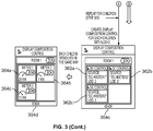
- FIG. 3 depicts one implementation of a process for constructing a visualization of an automation system using a graphical user interface provided by a software application, e.g., configuration interface application 215, which can be a web-based or native application, for example.
- the application can include Display Composition (DC) Point Manager 302, which interfaces with data storage (e.g., data storage device 220) to retrieve data objects, values, templates, and other information used in generating the visualization.
- DC Display Composition
- a visualization control (here, Display Composition (DC) Control 304a) is formed or otherwise instantiated by the application.
- the visualization control represents, in essence, a building block of the visualization, and is associated with an object in the automation system.
- the visualization control can include a reference (e.g., a link) to one or more objects in an object storage, such as object database 310, and, during instantiation of the control, the referenced object(s) can be retrieved from the object database 310 via DC Point Manager 302 interfacing with the object database 310 (STEP 353).
- Display Composition Control 304a includes a reference (Source: "dc://Room1") to object "Room 1" in the object database 310.
- Object database 310 can store an overall description of an automated system, i.e., its parts (assets), their relationships and hierarchy, visual representations of the system parts, and other information.
- objects are software-based representations of a physical or conceptual component, grouping, location, or any other portion of an automation system.
- the types of objects are virtually limitless and can include, for example, a room, a door, a building, a site, a valve, a gauge, a temperature sensor, a pressure sensor, a meter, a computer, an identification card reader, or a security camera.
- Objects can have various properties or parameters, such as the name of the object, the geographical coordinates of the object, whether the object is active, what child objects are associated with the object, and metadata defining visual properties of the object (e.g., screen location, size, color, associated graphics, etc.).
- An object can also include a reference to a visualization template, as further described below.
- objects are structured in one or more hierarchies within object database 310.
- a monitored automation system can have as the root of the hierarchy the monitored site, with children being individual buildings, and children of the buildings being individual rooms. Each room can then have children associated with monitored processes within, such as heating, cooling, assembly line, and so on, and the children of each of the foregoing include individual monitored components, such as thermostat, speed control, oil pressure sensor, etc.
- the hierarchy in object database 310 includes a "Room 1" object with child objects "Meter 1" through "Meter 4.”
- a visualization template is a generic form for a particular type of object (e.g., location, automation component such as a sensor or control, or other asset, as well as subcategories of the foregoing, such as assembly floor area, temperature sensor, and pressure release valve) that defines how the object can be visually structured and configured.
- the template can include parameters to which properties of an object can be mapped, saving the user from having to configure every object manually.
- the visualization template 328 is resolved by the object 322 (i.e., the properties of the object 322 are mapped to the parameters of the template 328, where applicable), forming a visualization 330 of the object 322.
- a template 328 for a "Room1" object 322, as shown in FIG. 3 can define a grid into which child objects are visually arranged, with a "#Name” parameter that the name of the "Room1" object 322 can be mapped to and, therefore, be shown on that visualization control.
- the "#On" property of the "Room1" object 322 can be mapped to the "#On” switch in the template 328.
- the template 328 also includes a "#Consumption” parameter, which represents a real-time display of energy usage cumulatively measured by the child objects (meters) in the room.
- "#Consumption” is defined as childObject1.consumption + childObject2.consumption + ... + childObjectN.consumption
- DC Control 304b can have associated metadata to define its visual properties (e.g., width, height, stretch, etc.) within the visualization interface.
- Multiple visualization controls can be combined and assembled together to form a comprehensive visualization interface of an automated system.
- objects received from the object database 310 include one or more child objects (and such child objects can have their own child objects, and so on).
- a process similar to the above described process can be performed.
- a DC Control for the child can be instantiated (corresponding to STEP 351)
- the child object and template referenced by the child object can be retrieved from object database 310 and template library storage 314, respectively (corresponding to STEPS 353 and 355)
- the child object and template can be resolved (corresponding to STEP 357), thereby generating a visualization of the child object.
- the visualization of the child object can then be assigned to and placed in the DC Control instantiated for the child object.
- the child DC control is also assigned to and placed in the DC control of its parent.
- each of the three child objects has instantiated a respective DC Control 362a-c, which are placed in the grid defined by the parent DC Control (now shown as DC Control 304c).
- meter visualizations 364a-c are generated and are displayed in the parent DC Control (now shown as DC Control 304d).
- an object can define, via properties, one or more automation control data sources (e.g., sensor data, status information, video feeds, etc.) to be associated with the object.
- one or more automation control data sources e.g., sensor data, status information, video feeds, etc.
- a user can manually associate a data source with the object.
- the data sources can provide real-time data so that a user can view information associated with the automation system (and, in some implementations, control the automation system) via the generated visualization in real-time.
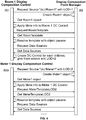
- FIG. 4 depicts example communication between DC Point Manager 302 and DC Control (i.e., DC Control 304a-d, collectively, DC Control 304), and then Meter 1 DC Control 362a, at various stages in the process illustrated by FIG. 3 .
- DC Control 304a-d DC Control 304a-d, collectively, DC Control 304
- Meter 1 DC Control 362a Meter 1 DC Control 362a
- FIG. 4 depicts example communication between DC Point Manager 302 and DC Control (i.e., DC Control 304a-d, collectively, DC Control 304), and then Meter 1 DC Control 362a, at various stages in the process illustrated by FIG. 3 .
- a request for the object referenced by DC Control 304 i.e., "Room1”
- a level of depth (LOD) parameter can be included with the request, which specifies how deep in the hierarchy a particular object is and, in some instances, how it can be represented in the resulting visualization.
- LOD level of depth
- Room1 has an LOD of 1, as it is a top level object, whereas the child objects of Room1 will have LODs of 2 or higher.
- DC Point Manager 302 creates the object 322 (e.g., instantiates a software object or data structure including properties of the object stored in object storage 310) and returns the object 322 to DC Control 304 (STEP 353). Metadata associated with the object 322 can be applied to the DC Control 304 to set the visual properties of the DC Control 304 as appropriate for the object 322.
- DC Control 304 then makes a request for the visualization template 328 referenced by the object 322.
- DC Point Manager 302 returns the template 328 to the DC Control 304 (STEP 355), which proceeds to perform the above-described resolving process between the object properties and template parameters (STEP 357).
- DC Control 304 further requests data sources defined by the object 322 from DC Point Manager 302.
- data sources can include real-time or non-real-time data feeds associated with the object 322, such as sensor readings or other process control data.
- These data sources can be associated with the visualization control (DC Control 304) to provide users with various forms of process control data via the overall visualization.
- DC Control 362a-362c Similar communication occurs for child objects, if any, of the (parent) object 322 (corresponds to STEP 359 of FIG. 3 ).
- a DC Control 362a-362c is created for each child object.
- each child object communicates with DC Point Manager 302, serially or in parallel, to automatically configure itself.
- DC Control 362a requests its corresponding object (i.e., "Meter1") from DC Point Manager 302, which creates and returns the requested child object. Metadata defining visual properties associated with the Meter1 child object can then be applied to the Meter1 DC Control 362a.
- the visualization template referenced by the Meter1 object is requested from DC Point Manager 302, which returns the generic Meter template in response.
- DC Control 362a maps the Meter1 object properties to the Meter template parameters, resulting in a visualization 364a of Meter1.
- a data source can be requested from DC Point Manager 302 and, when received, can be associated with the Meter1 DC Control 362a.
- sensor readings associated with the actual corresponding meter in the automation system can be associated with the Meter1 DC Control 362a and visually represented to the user via, e.g., a graphical depiction of a meter.
Landscapes
- Engineering & Computer Science (AREA)
- General Engineering & Computer Science (AREA)
- Theoretical Computer Science (AREA)
- Physics & Mathematics (AREA)
- General Physics & Mathematics (AREA)
- Human Computer Interaction (AREA)
- Software Systems (AREA)
- Automation & Control Theory (AREA)
- User Interface Of Digital Computer (AREA)
Description
- The present disclosure relates generally to user interfaces and, more particularly, to systems and methods for dynamically created and configurable visualization interfaces for automation systems.
- Process monitoring and control relates to the viewing and control of parameters of one or more processes, environments in which the processes are performed, and/or the operation of equipment executing the processes. In the manufacturing context, for example, process parameters can include duration, temperature, pressure, speed, quantity, and/or direction of motion of a particular piece of machinery. In other processes, such as in those performed in the course of using and maintaining information systems, management systems, and the like, the parameters can include to temperature of the operating environment, throughput (transactional and/or packet-based), downtime, usage, and similar quantities.
- Automation, or process control, systems can be used to help manage production, monitor and maintain equipment, view performance and operational trends, and/or perform business functions such as remotely modifying operational parameters, visual inspections, and maintenance scheduling. However, user interfaces in modern automation systems are exceedingly complex, and the configuration of such interfaces is generally a substantially time consuming and error-prone process. Accordingly, personnel who create, set up, and use such automation systems would benefit from enhanced techniques for generating and configuring visualization interfaces to reduce the required engineering work and increase the accuracy and efficiency of these processes.
-
EP 2 728 427 (Rockwell, 2014 - Described herein is a new dynamically configurable and re-configurable visualization system usable with, for example, automation and operational process control systems. A dynamic asset-driven visualization provides numerous possibilities for automatic composition of visualization displays at run-time, on-the-fly, based on the user request. Fast re-configuration of a production plant or other system allows an agile reorganization of assets, reduces the cost of reorganization, and better utilizes the resources of the system
- Accordingly, in one aspect, a computer-implemented method for creating an automation system visualization is disclosed. An application that includes a graphical user interface for constructing a visualization of an automation system is provided. The automation system includes a plurality of objects that can be organized, for example, in a hierarchy. The application forms a visualization control that is a building block of the visualization of the automation system. The visualization control is associated with a first object in the plurality of objects. The first object, which includes (i) a reference to a first visualization template and (ii) a plurality of properties associated with the first object, is received from an object storage. The referenced first visualization template is received from a template storage. The application then generates a visualization of the first object by mapping the properties associated with the first object to the visualization template, and assigns the visualization of the first object to the visualization control.
- The first visualization template can be a generic form of a type (e.g., location, sensor, control, etc.) of the first object, and can include a plurality of parameters to which one or more of the properties of the first object are mapped. The visualization control itself can include metadata defining its visual properties. An automation control data source can also be assigned to the visualization control.
- In one implementation, at least steps (c) through (e) are repeated for each child object in the first object. The application can form additional respective visualization controls for each child object in the first object, and place the additional visualization controls in the parent visualization control based on the first visualization template. In one instance, the first object defines a location, and the child objects define automation system assets at the location.
- Ultimately, the visualization of the automation system can be made up of a plurality of visualization controls generated based on respective objects and templates.
- Other aspects and implementations of the above include corresponding systems and non-transitory computer-readable media. Further aspects and advantages of the invention will become apparent from the following drawings, detailed description, and claims, all of which illustrate the principles of the invention, by way of example only.
- A more complete appreciation of the invention and many attendant advantages thereof will be readily obtained as the same becomes better understood by reference to the following detailed description when considered in connection with the accompanying drawings. In the drawings, like reference characters generally refer to the same parts throughout the different views. Further, the drawings are not necessarily to scale, with emphasis instead generally being placed upon illustrating the principles of the invention.
-
FIG. 1 depicts a general environment in which various implementations of the disclosed techniques can operate. -
FIG. 2 depicts an example application framework according to an implementation. -
FIG. 3 depicts an example method for generating a visualization according to an implementation. -
FIG. 4 depicts an example information flow in generating a visualization according to an implementation. - Described in various implementations herein are systems and methods for providing a visualization (e.g., a graphical representation and/or user interface) of an automation (process control) system, such as a manufacturing, industrial, energy, water treatment, or building (e.g., heating, air conditioning and ventilation) automation system, by dynamically generating and configuring the visualization from a system description stored in an asset (e.g., a software-based object) in combination with configuration template objects.
-
FIG. 1 depicts an exemplaryautomation system environment 100 for which an control interface can be generated and configured using various implementations of the present techniques. Theenvironment 100 includes operational components that collect, analyze, present, and act on operational process control (OPC) data as it is generated and collected. The OPC data is generated and collected at ormore facilities - To monitor individual processes and controls at each facility 105,
process control equipment process control equipment 110 can be collected for the entire facility and reported at a facility-specific OPC server - In some implementations, a centralized data collection and reporting system can consolidate, aggregate and/or compare data collected from each facility 105 and the
various processes 110 operating at each facility 105. In such cases, anenterprise OPC server 120 can communicate with the facility-specific OPC servers 115, theindividual controllers 110 continuously or periodically using one or more data communications services. Theenterprise OPC server 120 can in turnsupport client workstations - Some or all of the components described above can be connected by and communicate via a
network 130. The communication can take place via any media such as standard telephone lines, LAN or WAN links (e.g., T1, T3, 56 kb, X.25), broadband connections (ISDN, Frame Relay, ATM), wireless links, and so on. Thenetwork 130 can carry TCP/IP protocol communications, and HTTP/HTTPS requests made by a web browser and the connections among thecontrollers 110, the facility-specific OPC servers 115, theenterprise OPC server 120 and theclient workstations 125 can be communicated over such TCP/IP networks. The type of network is not a limitation, however, and any suitable network can be used. Typical examples of networks that can serve as thecommunications network 130 include a wireless or wired Ethernet-based intranet, a local or wide-area network (LAN or WAN), and/or the internet, which can accommodate many different communications media and protocols. -
FIG. 2 illustrates anexemplary system 200 for collecting and reporting OPC data, including anapplication server 205, adata visualization server 210, and aconfiguration user interface 215 that each can operate in concert with one or more OPC servers. Thesystem 200 can also include one or moredata storage devices 220 for storing, among other things, configuration parameters that define the OPC servers, software-based objects and other data structures that define individual components in an automation system and their associated properties, and templates that are used in the configuration of automation system visualizations. Data storage device(s) 220 can include a non-transitory computer-readable storage medium, such as a hard disk drive, solid-state drive, random access memory, etc., and can store data in the form of a database, individual files, and so on. - The
application server 205 provides data collection, aggregation and transformation processing for the system. For example, theapplication server 205 includes acommunication stack 240 that allows theapplication server 205 to request and/or receive data from individual OPC servers 115, send data to thedata visualization server 210 for charting and reporting, and theclient workstations 125. Thecommunications stack 240 includes a series of layered protocols for packaging and transmitting data among computers over a network. In some implementations, the communications stack provides TCP/IP-based communications among the system components to allow data to be sent via HTTP requests, XML/Web Services, and similar methods. - The
application server 205 also includes a unifieddata manager component 245 for manipulating data received from the various OPC servers 115. In many implementations, data is collected from processes and facilities with little or no defined relationship among the data elements. For example, a shift supervisor can enter comments into an electronic log, and the comments receive timestamps and an operator ID. At the same time, OPC devices can collect processing data such as throughput (e.g., pieces/hour) and quality measurements (e.g., defects/100 pieces), all of which are measured using different units (if any) and relating to different aspects of the facility. The unifieddata manager component 245 analyzes the incoming data and applies a rules-based algorithm to allow the data to be reported and charted using common units. - In some implementations, the
application server 205 also includes anOPC engine 250 for analyzing the OPC data as it is collected (either in real-time or asynchronously) and determining what subsequent processing, events and/or alarms are appropriate. For example, a set of rules can be defined such that the certain events (e.g., non-receipt of data, a data value outside a preferred range, etc.) warrant an alarm to be triggered and sent to aclient workstation 125. In some instances theOPC engine 250 formats the data for presentation on reports and charts. - The
data visualization server 210 receives data from theapplication server 205 and presents it at thevisualization server 210 and/or at one ormore clients 125. The data can be presented in various forms, such as raw tabular form, text-based reports, graphical reports, and real-time graphical representations of the monitored processes enhanced with additional data (e.g., supply-chain data, inventory data, financial data, etc.), alarms, and visual indicators relating to the processes. Areporting engine 255 utilizes pre-defined report formats and includes graphical tool-kits that facilitate the design of custom graphs based on user and/or process-specific requirements. In some implementations, OPC data is annotated with workflow information, such as a distribution list identifying recipients (e.g., individuals, workstations, or other systems) to which the data is to be sent. In some instances, the OPC data is available in raw format according to one or more OPC standards using commonly-used data publishing techniques such as web services. In other cases, reports and/or data can be sent in-preformatted reports or as a stream of data used by a client application. In such cases, aworkflow engine 260 manages the distribution of data and/or reports according to workflow rules associated therewith. -
Configuration interface application 215 allows users to generate and configure, in an at least partially automated manner, a visualization of an automated system for presentation viavisualization server 210, as further described below. - The techniques described herein can be implemented in appropriate hardware or software. The
system 200 can include, for example, clients and servers capable of running one or more commercial operating systems such as the Microsoft Windows® operating systems, the Apple OS X® operating systems, the Linux® operating system and other variants of UNIX® operating systems, and the like. Clients can include, for example, a workstation, a smart or dumb terminal, network computer, smartphone, tablet, laptop, palmtop, wireless telephone, television, information appliance, wireless device, minicomputer, mainframe computer, or other computing device, that is operated as a general purpose computer or a special purpose hardware device that can execute the functionality described herein. Generally, software executing on devices in thesystem 200 can be implemented on a computer including a processing unit, a system memory, and a system bus that couples various system components including the system memory to the processing unit. - The software architecture of the visualization system components can include a plurality of software modules stored in a memory and executed on one or more processors. The modules can be in the form of a suitable programming language, which is converted to machine language or object code to allow the processor or processors to read the instructions. The software can be in the form of a standalone application, implemented in any suitable programming language or framework. The visualization system and associated components can be implemented as native applications, web applications, or other form of software. In some implementations, a particular application is in the form of a web page, widget, and/or Java, JavaScript, .Net, Silverlight, Flash, and/or other applet or plug-in that is downloaded to a user device and runs in conjunction with a web browser. An application and a web browser can be part of a single client-server interface; for example, an application can be implemented as a plugin to the web browser or to another framework or operating system. Any other suitable client software architecture, including but not limited to widget frameworks and applet technology can also be employed.
- Method steps of the techniques described herein can be performed by one or more programmable processors executing a computer program to perform functions of the invention by operating on input data and generating output. Method steps can also be performed by, and apparatus of the invention can be implemented as, special purpose logic circuitry, e.g., an FPGA (field programmable gate array) or an ASIC (application-specific integrated circuit). Modules can refer to portions of the computer program and/or the processor/special circuitry that implements that functionality.
- Processors suitable for the execution of a computer program include, by way of example, both general and special purpose microprocessors, and any one or more processors of any kind of digital computer. Generally, a processor will receive instructions and data from a read-only memory or a random access memory or both. The essential elements of a computer are a processor for executing instructions and one or more memory devices for storing instructions and data. Information carriers suitable for embodying computer program instructions and data include all forms of non-volatile memory, including by way of example semiconductor memory devices, e.g., EPROM, EEPROM, and flash memory devices; magnetic disks, e.g., internal hard disks or removable disks; magneto-optical disks; and CD-ROM and DVD-ROM disks. One or more memories can store media assets (e.g., audio, video, graphics, interface elements, and/or other media files), configuration files, and/or instructions that, when executed by a processor, form the modules, engines, and other components described herein and perform the functionality associated with the components. The processor and the memory can be supplemented by, or incorporated in special purpose logic circuitry.
- It should also be noted that the present implementations can be provided as one or more computer-readable programs embodied on or in one or more articles of manufacture. The article of manufacture can be any suitable hardware apparatus, such as, for example, a floppy disk, a hard disk, a CD-ROM, a CD-RW, a CD-R, a DVD-ROM, a DVD-RW, a DVD-R, a flash memory card, a PROM, a RAM, a ROM, or a magnetic tape. In general, the computer-readable programs can be implemented in any programming language. The software programs can be further translated into machine language or virtual machine instructions and stored in a program file in that form. The program file can then be stored on or in one or more of the articles of manufacture.
-
FIG. 3 depicts one implementation of a process for constructing a visualization of an automation system using a graphical user interface provided by a software application, e.g.,configuration interface application 215, which can be a web-based or native application, for example. The application can include Display Composition (DC)Point Manager 302, which interfaces with data storage (e.g., data storage device 220) to retrieve data objects, values, templates, and other information used in generating the visualization. - In
STEP 351, a visualization control (here, Display Composition (DC)Control 304a) is formed or otherwise instantiated by the application. The visualization control represents, in essence, a building block of the visualization, and is associated with an object in the automation system. The visualization control can include a reference (e.g., a link) to one or more objects in an object storage, such asobject database 310, and, during instantiation of the control, the referenced object(s) can be retrieved from theobject database 310 viaDC Point Manager 302 interfacing with the object database 310 (STEP 353). As shown inFIG. 3 ,Display Composition Control 304a includes a reference (Source: "dc://Room1") to object "Room 1" in theobject database 310. -
Object database 310 can store an overall description of an automated system, i.e., its parts (assets), their relationships and hierarchy, visual representations of the system parts, and other information. In one implementation, objects are software-based representations of a physical or conceptual component, grouping, location, or any other portion of an automation system. The types of objects are virtually limitless and can include, for example, a room, a door, a building, a site, a valve, a gauge, a temperature sensor, a pressure sensor, a meter, a computer, an identification card reader, or a security camera. Objects can have various properties or parameters, such as the name of the object, the geographical coordinates of the object, whether the object is active, what child objects are associated with the object, and metadata defining visual properties of the object (e.g., screen location, size, color, associated graphics, etc.). An object can also include a reference to a visualization template, as further described below. - In some implementations, objects are structured in one or more hierarchies within
object database 310. For example, a monitored automation system can have as the root of the hierarchy the monitored site, with children being individual buildings, and children of the buildings being individual rooms. Each room can then have children associated with monitored processes within, such as heating, cooling, assembly line, and so on, and the children of each of the foregoing include individual monitored components, such as thermostat, speed control, oil pressure sensor, etc. In the depicted example inFIG. 3 , the hierarchy inobject database 310 includes a "Room 1" object with child objects "Meter 1" through "Meter 4." - In
STEP 355, thevisualization template 328 referenced by the retrievedobject 322 is retrieved fromtemplate library storage 314 viaDC Point Manager 302 interfacing with thetemplate library storage 314. Here, inFIG. 3 , thetemplate 328 retrieved is the "RoomTemplate" associated with the "Room1"object 322. In one implementation, a visualization template is a generic form for a particular type of object (e.g., location, automation component such as a sensor or control, or other asset, as well as subcategories of the foregoing, such as assembly floor area, temperature sensor, and pressure release valve) that defines how the object can be visually structured and configured. The template can include parameters to which properties of an object can be mapped, saving the user from having to configure every object manually. - Accordingly, in
STEP 357, thevisualization template 328 is resolved by the object 322 (i.e., the properties of theobject 322 are mapped to the parameters of thetemplate 328, where applicable), forming avisualization 330 of theobject 322. For example, atemplate 328 for a "Room1"object 322, as shown inFIG. 3 , can define a grid into which child objects are visually arranged, with a "#Name" parameter that the name of the "Room1"object 322 can be mapped to and, therefore, be shown on that visualization control. Similarly, the "#On" property of the "Room1"object 322 can be mapped to the "#On" switch in thetemplate 328. Here, thetemplate 328 also includes a "#Consumption" parameter, which represents a real-time display of energy usage cumulatively measured by the child objects (meters) in the room. In other words, "#Consumption" is defined as childObject1.consumption + childObject2.consumption + ... + childObjectN.consumption - Ultimately, the generated
visualization 330 is assigned to and placed into the DC Control (shown asDC Control 304b inFIG. 3 ).DC Control 304b can have associated metadata to define its visual properties (e.g., width, height, stretch, etc.) within the visualization interface. Multiple visualization controls can be combined and assembled together to form a comprehensive visualization interface of an automated system. - In some implementations, objects received from the
object database 310 include one or more child objects (and such child objects can have their own child objects, and so on). For each child object, a process similar to the above described process can be performed. In particular, a DC Control for the child can be instantiated (corresponding to STEP 351), the child object and template referenced by the child object can be retrieved fromobject database 310 andtemplate library storage 314, respectively (corresponding toSTEPS 353 and 355), and the child object and template can be resolved (corresponding to STEP 357), thereby generating a visualization of the child object. The visualization of the child object can then be assigned to and placed in the DC Control instantiated for the child object. Further, in some instances, the child DC control is also assigned to and placed in the DC control of its parent. For example, as shown inFIG. 3 , each of the three child objects (Meter 1,Meter 2, and Meter 3) has instantiated arespective DC Control 362a-c, which are placed in the grid defined by the parent DC Control (now shown asDC Control 304c). In resolving the child objects and templates,meter visualizations 364a-c are generated and are displayed in the parent DC Control (now shown asDC Control 304d). - In some implementations, an object can define, via properties, one or more automation control data sources (e.g., sensor data, status information, video feeds, etc.) to be associated with the object. In some instances, a user can manually associate a data source with the object. The data sources can provide real-time data so that a user can view information associated with the automation system (and, in some implementations, control the automation system) via the generated visualization in real-time.
-
FIG. 4 depicts example communication betweenDC Point Manager 302 and DC Control (i.e.,DC Control 304a-d, collectively, DC Control 304), and thenMeter 1DC Control 362a, at various stages in the process illustrated byFIG. 3 . Upon instantiatingDC Control 304 atSTEP 351, a request for the object referenced by DC Control 304 (i.e., "Room1") is made toDC Point Manager 302. A level of depth (LOD) parameter can be included with the request, which specifies how deep in the hierarchy a particular object is and, in some instances, how it can be represented in the resulting visualization. So, for example, Room1 has an LOD of 1, as it is a top level object, whereas the child objects of Room1 will have LODs of 2 or higher. In response,DC Point Manager 302 creates the object 322 (e.g., instantiates a software object or data structure including properties of the object stored in object storage 310) and returns theobject 322 to DC Control 304 (STEP 353). Metadata associated with theobject 322 can be applied to theDC Control 304 to set the visual properties of theDC Control 304 as appropriate for theobject 322.DC Control 304 then makes a request for thevisualization template 328 referenced by theobject 322. In response,DC Point Manager 302 returns thetemplate 328 to the DC Control 304 (STEP 355), which proceeds to perform the above-described resolving process between the object properties and template parameters (STEP 357). - In some implementations,
DC Control 304 further requests data sources defined by theobject 322 fromDC Point Manager 302. Such data sources can include real-time or non-real-time data feeds associated with theobject 322, such as sensor readings or other process control data. These data sources can be associated with the visualization control (DC Control 304) to provide users with various forms of process control data via the overall visualization. - Similar communication occurs for child objects, if any, of the (parent) object 322 (corresponds to STEP 359 of
FIG. 3 ). Initially, aDC Control 362a-362c is created for each child object. Then, each child object communicates withDC Point Manager 302, serially or in parallel, to automatically configure itself. For example, as shown inFIG. 4 ,DC Control 362a requests its corresponding object (i.e., "Meter1") fromDC Point Manager 302, which creates and returns the requested child object. Metadata defining visual properties associated with the Meter1 child object can then be applied to theMeter1 DC Control 362a. Further, the visualization template referenced by the Meter1 object is requested fromDC Point Manager 302, which returns the generic Meter template in response.DC Control 362a maps the Meter1 object properties to the Meter template parameters, resulting in avisualization 364a of Meter1. Again, a data source can be requested fromDC Point Manager 302 and, when received, can be associated with theMeter1 DC Control 362a. In this case, sensor readings associated with the actual corresponding meter in the automation system can be associated with theMeter1 DC Control 362a and visually represented to the user via, e.g., a graphical depiction of a meter. - To the extent that additional children (or children of children, and so on) exist, the process can continue in the same manner to generate and configure each corresponding DC Control, ultimately resulting in an easily generated and automatically configured visualization of an automated system.
- While various implementations of the present invention have been described herein, it should be understood that they have been presented by example only. Where methods and steps described above indicate certain events occurring in certain order, those of ordinary skill in the art having the benefit of this disclosure would recognize that the ordering of certain steps can be modified and that such modifications are in accordance with the given variations. For example, although various implementations have been described as having particular features and/or combinations of components, other implementations are possible having any combination or sub-combination of any features and/or components from any of the implementations described herein.
Claims (14)
- A computer-implemented method for dynamically creating a visualization graphical user interface for an automation system, the method comprising:(a) providing an application comprising a graphical user interface for constructing a visualization of an automation system, the automation system comprising a plurality of objects;(b) forming (STEP 351), by the application, a first visualization control (304) comprising a building block of the visualization of the automation system, wherein the first visualization control (304) is associated with a first object (322) in the plurality of objects;(c) receiving (STEP 353) objects from an object storage (310), the objects including the first object (322) and a plurality of children of the first object (322), the first object (322) being referenced by the first visualization control (304), wherein metadata associated with the first object (322) sets visual properties of the first visualization control (304), the first object (322) comprising (i) a reference to a first visualization template (328) and (ii) a plurality of properties associated with the first object (322), wherein the first visualization template (328) comprises a generic form of the first object (322) defining how the first object (322) can be visually structured and configured;(d) receiving (STEP 355) the first visualization template (328) referenced by the first object (322) from a template storage (314);(e) generating (STEP 357), by the application, a visualization (330) of the first object (322) by mapping the properties associated with the first object (322) to the first visualization template (328);(f) assigning, by the application, the visualization (330) of the first object (322) to the first visualization control (304);(g) forming (STEP 359), by the application, a respective visualization control (362a,362b,362c) for each child of the first object (322), wherein each child of the first object (322) automatically configures itself by:requesting, by the visualization control (362a, 362b, 362c) for the child, a child object corresponding to the child from the object storage (310);receiving the child object from the object storage (310), the child object comprising (i) a reference to a second visualization template and (ii) a plurality of properties associated with the child object; andgenerating, by the application, a visualization (364a,364b,364c) of the child object by mapping the properties associated with the child object to the second Visualization template and assigning, by the application, the visualization (364a,364b,364c) of the child object to the visualization control (362a,362b,362c) for the child; and(h) placing the visualization control (362a,362b,362c) for each child of the first object (322) in the first visualization control (304) based on the first visualization template (328).
- The method of claim 1, wherein the plurality of objects forms a hierarchy of the objects.
- The method of claim 1, wherein the first visualization template (328) comprises a plurality of parameters to which one or more of the properties of the first object (322) are mapped.
- The method of claim 3, wherein a type of the first object (322) or of a child object of the first object (322) comprises a location, a sensor, or a control.
- The method of claim 1, further comprising assigning an automation control data source to the first visualization control (304), wherein the automation control data source includes data feeds associated with the first object (322).
- The method of claim 1, wherein the first object (322) comprises a room and the child objects comprise automation system assets in the room.
- The method of claim 1, wherein the visualization of the automation system comprises a plurality of visualization controls generated based on respective objects and templates.
- A system for dynamically creating a visualization graphical user interface for an automation system, the method comprising:at least one memory for storing computer-executable instructions;at least one processing unit for executing the instructions, wherein execution of the instructions programs the at least one processing unit to perform operations comprising:(a) providing an application comprising a graphical user interface for constructing a visualization of an automation system, the automation system comprising a plurality of objects;(b) forming, by the application, a first visualization control (304) comprising a building block of the visualization of the automation system, wherein the first visualization control (304) is associated with a first object (322) in the plurality of objects;(c) receiving objects from an object storage (310), the objects including the first object (322) and a plurality of children of the first object (322), the first object (322) being referenced by the first visualization control (304), wherein metadata associated with the first object (322) sets visual properties of the first visualization control (304), the first object (322) comprising (i) a reference to a first visualization template (328) and (ii) a plurality of properties associated with the first object (322), wherein the first visualization template (328) comprises a generic form of the first object (322) defining how the first object (322) can be visually structured and configured;(d) receiving the first visualization template (328) referenced by the first object (322) from a template storage (314);(e) generating, by the application, a visualization (330) of the first object (322) by mapping the properties associated with the first object (322) to the first visualization template (328);(f) assigning, by the application, the visualization (330) of the first object (322) to the first visualization control (304);(g) forming, by the application, a respective visualization control (362a,362b,362c) for each child of the first object (322), wherein each child of the first object (322) automatically configures itself by:requesting, by the visualization control (362a,362b,362c) for the child, a child object corresponding to the child from the object storage (310);receiving the child object from the object storage (310), the child object comprising (i) a reference to a second visualization template and (ii) a plurality of properties associated with the child object; andgenerating, by the application, a visualization (364a,364b,364c) of the child object by mapping the properties associated with the child object to the second visualization template and assigning, by the application, the visualization (364a,364b,364c) of the child object to the visualization control (362a,362b,362c) for the child; and(h) placing the visualization control (362a, 362b, 362c) for each child of the first object (322) in the first visualization control (304) based on the first visualization template (328).
- The system of claim 8, wherein the plurality of objects forms a hierarchy of the objects.
- The system of claim 9, wherein the first visualization template (328) comprises a plurality of parameters to which one or more of the properties of the first object (322) are mapped.
- The system of claim 10, wherein a type of the first object (322) or of a child object of the first object (322) comprises a location, a sensor, or a control.
- The system of claim 9, wherein the first visualization control (304) comprises metadata defining visual properties of the first visualization control (304);
wherein the operations may further comprise assigning an automation control data source to the first visualization control (304), wherein the automation control data source includes data feeds associated with the first object (322). - The system of claim 9, wherein the first object (322) comprises a room and the child objects comprise automation system assets in the room.
- The system of claim 9, wherein the visualization of the automation system comprises a plurality of visualization controls generated based on respective objects and templates.
Applications Claiming Priority (3)
| Application Number | Priority Date | Filing Date | Title |
|---|---|---|---|
| US201562185335P | 2015-06-26 | 2015-06-26 | |
| US15/190,400 US10282071B2 (en) | 2015-06-26 | 2016-06-23 | Asset-driven dynamically composed visualization system |
| PCT/US2016/039249 WO2016210264A1 (en) | 2015-06-26 | 2016-06-24 | Asset-driven dynamically composed visualization system |
Publications (2)
| Publication Number | Publication Date |
|---|---|
| EP3314414A1 EP3314414A1 (en) | 2018-05-02 |
| EP3314414B1 true EP3314414B1 (en) | 2020-03-11 |
Family
ID=56551543
Family Applications (1)
| Application Number | Title | Priority Date | Filing Date |
|---|---|---|---|
| EP16744958.6A Revoked EP3314414B1 (en) | 2015-06-26 | 2016-06-24 | Asset-driven dynamically composed visualization system |
Country Status (3)
| Country | Link |
|---|---|
| US (1) | US10282071B2 (en) |
| EP (1) | EP3314414B1 (en) |
| WO (1) | WO2016210264A1 (en) |
Families Citing this family (85)
| Publication number | Priority date | Publication date | Assignee | Title |
|---|---|---|---|---|
| US9411327B2 (en) | 2012-08-27 | 2016-08-09 | Johnson Controls Technology Company | Systems and methods for classifying data in building automation systems |
| US10282071B2 (en) | 2015-06-26 | 2019-05-07 | Iconics, Inc. | Asset-driven dynamically composed visualization system |
| US10534326B2 (en) | 2015-10-21 | 2020-01-14 | Johnson Controls Technology Company | Building automation system with integrated building information model |
| US12196437B2 (en) | 2016-01-22 | 2025-01-14 | Tyco Fire & Security Gmbh | Systems and methods for monitoring and controlling an energy plant |
| US11268732B2 (en) | 2016-01-22 | 2022-03-08 | Johnson Controls Technology Company | Building energy management system with energy analytics |
| US11947785B2 (en) | 2016-01-22 | 2024-04-02 | Johnson Controls Technology Company | Building system with a building graph |
| WO2017173167A1 (en) | 2016-03-31 | 2017-10-05 | Johnson Controls Technology Company | Hvac device registration in a distributed building management system |
| US10901373B2 (en) | 2017-06-15 | 2021-01-26 | Johnson Controls Technology Company | Building management system with artificial intelligence for unified agent based control of building subsystems |
| US10505756B2 (en) | 2017-02-10 | 2019-12-10 | Johnson Controls Technology Company | Building management system with space graphs |
| US11774920B2 (en) | 2016-05-04 | 2023-10-03 | Johnson Controls Technology Company | Building system with user presentation composition based on building context |
| US10417451B2 (en) | 2017-09-27 | 2019-09-17 | Johnson Controls Technology Company | Building system with smart entity personal identifying information (PII) masking |
| US10684033B2 (en) | 2017-01-06 | 2020-06-16 | Johnson Controls Technology Company | HVAC system with automated device pairing |
| US11900287B2 (en) | 2017-05-25 | 2024-02-13 | Johnson Controls Tyco IP Holdings LLP | Model predictive maintenance system with budgetary constraints |
| US10452043B2 (en) | 2017-02-10 | 2019-10-22 | Johnson Controls Technology Company | Building management system with nested stream generation |
| US11360447B2 (en) | 2017-02-10 | 2022-06-14 | Johnson Controls Technology Company | Building smart entity system with agent based communication and control |
| US11764991B2 (en) | 2017-02-10 | 2023-09-19 | Johnson Controls Technology Company | Building management system with identity management |
| US11307538B2 (en) | 2017-02-10 | 2022-04-19 | Johnson Controls Technology Company | Web services platform with cloud-eased feedback control |
| US10095756B2 (en) | 2017-02-10 | 2018-10-09 | Johnson Controls Technology Company | Building management system with declarative views of timeseries data |
| US10515098B2 (en) | 2017-02-10 | 2019-12-24 | Johnson Controls Technology Company | Building management smart entity creation and maintenance using time series data |
| US10854194B2 (en) | 2017-02-10 | 2020-12-01 | Johnson Controls Technology Company | Building system with digital twin based data ingestion and processing |
| US11994833B2 (en) | 2017-02-10 | 2024-05-28 | Johnson Controls Technology Company | Building smart entity system with agent based data ingestion and entity creation using time series data |
| US12184444B2 (en) | 2017-02-10 | 2024-12-31 | Johnson Controls Technology Company | Space graph based dynamic control for buildings |
| US11042144B2 (en) | 2017-03-24 | 2021-06-22 | Johnson Controls Technology Company | Building management system with dynamic channel communication |
| US11327737B2 (en) | 2017-04-21 | 2022-05-10 | Johnson Controls Tyco IP Holdings LLP | Building management system with cloud management of gateway configurations |
| US10788229B2 (en) | 2017-05-10 | 2020-09-29 | Johnson Controls Technology Company | Building management system with a distributed blockchain database |
| WO2018217251A1 (en) | 2017-05-25 | 2018-11-29 | Johnson Controls Technology Company | Model predictive maintenance system for building equipment |
| US11022947B2 (en) | 2017-06-07 | 2021-06-01 | Johnson Controls Technology Company | Building energy optimization system with economic load demand response (ELDR) optimization and ELDR user interfaces |
| US12597772B2 (en) | 2017-06-07 | 2026-04-07 | Tyco Fire & Security Gmbh | Central plant control system with asset allocation override |
| WO2019018304A1 (en) | 2017-07-17 | 2019-01-24 | Johnson Controls Technology Company | Systems and methods for agent based building simulation for optimal control |
| EP3655825B1 (en) | 2017-07-21 | 2023-11-22 | Johnson Controls Tyco IP Holdings LLP | Building management system with dynamic rules with sub-rule reuse and equation driven smart diagnostics |
| US10648692B2 (en) | 2017-07-27 | 2020-05-12 | Johnson Controls Technology Company | Building management system with multi-dimensional analysis of building energy and equipment performance |
| DE112018004325T5 (en) | 2017-09-27 | 2020-05-14 | Johnson Controls Technology Company | SYSTEMS AND METHODS FOR RISK ANALYSIS |
| US11314788B2 (en) | 2017-09-27 | 2022-04-26 | Johnson Controls Tyco IP Holdings LLP | Smart entity management for building management systems |
| US20190095821A1 (en) | 2017-09-27 | 2019-03-28 | Johnson Controls Technology Company | Building risk analysis system with expiry time prediction for threats |
| US10962945B2 (en) | 2017-09-27 | 2021-03-30 | Johnson Controls Technology Company | Building management system with integration of data into smart entities |
| US11120012B2 (en) | 2017-09-27 | 2021-09-14 | Johnson Controls Tyco IP Holdings LLP | Web services platform with integration and interface of smart entities with enterprise applications |
| US11281169B2 (en) | 2017-11-15 | 2022-03-22 | Johnson Controls Tyco IP Holdings LLP | Building management system with point virtualization for online meters |
| US10809682B2 (en) | 2017-11-15 | 2020-10-20 | Johnson Controls Technology Company | Building management system with optimized processing of building system data |
| US11127235B2 (en) | 2017-11-22 | 2021-09-21 | Johnson Controls Tyco IP Holdings LLP | Building campus with integrated smart environment |
| US11014466B2 (en) | 2018-01-12 | 2021-05-25 | Johnson Controls Technology Company | Building energy optimization system with battery powered vehicle cost optimization |
| US11954713B2 (en) | 2018-03-13 | 2024-04-09 | Johnson Controls Tyco IP Holdings LLP | Variable refrigerant flow system with electricity consumption apportionment |
| JP7171256B2 (en) * | 2018-06-14 | 2022-11-15 | キヤノン株式会社 | Communication system, control method and program |
| US11016648B2 (en) | 2018-10-30 | 2021-05-25 | Johnson Controls Technology Company | Systems and methods for entity visualization and management with an entity node editor |
| US20200162280A1 (en) | 2018-11-19 | 2020-05-21 | Johnson Controls Technology Company | Building system with performance identification through equipment exercising and entity relationships |
| US12367443B2 (en) | 2019-01-14 | 2025-07-22 | Tyco Fire & Security Gmbh | System and method for showing key performance indicators |
| US11132649B2 (en) | 2019-01-18 | 2021-09-28 | Johnson Controls Tyco IP Holdings LLP | Smart parking lot system |
| US10788798B2 (en) | 2019-01-28 | 2020-09-29 | Johnson Controls Technology Company | Building management system with hybrid edge-cloud processing |
| US11362852B2 (en) * | 2019-05-08 | 2022-06-14 | Johnson Controls Tyco IP Holdings LLP | Systems and methods for configuring and operating building equipment using causal and spatial relationships |
| US12197299B2 (en) | 2019-12-20 | 2025-01-14 | Tyco Fire & Security Gmbh | Building system with ledger based software gateways |
| US20210200713A1 (en) | 2019-12-31 | 2021-07-01 | Johnson Controls Technology Company | Systems and methods for generating a data structure from multiple bim files |
| US11894944B2 (en) | 2019-12-31 | 2024-02-06 | Johnson Controls Tyco IP Holdings LLP | Building data platform with an enrichment loop |
| US11769066B2 (en) | 2021-11-17 | 2023-09-26 | Johnson Controls Tyco IP Holdings LLP | Building data platform with digital twin triggers and actions |
| US12021650B2 (en) | 2019-12-31 | 2024-06-25 | Tyco Fire & Security Gmbh | Building data platform with event subscriptions |
| EP4085345A1 (en) | 2019-12-31 | 2022-11-09 | Johnson Controls Tyco IP Holdings LLP | Building data platform |
| US12100280B2 (en) | 2020-02-04 | 2024-09-24 | Tyco Fire & Security Gmbh | Systems and methods for software defined fire detection and risk assessment |
| US11537386B2 (en) | 2020-04-06 | 2022-12-27 | Johnson Controls Tyco IP Holdings LLP | Building system with dynamic configuration of network resources for 5G networks |
| US11874809B2 (en) | 2020-06-08 | 2024-01-16 | Johnson Controls Tyco IP Holdings LLP | Building system with naming schema encoding entity type and entity relationships |
| US11954154B2 (en) | 2020-09-30 | 2024-04-09 | Johnson Controls Tyco IP Holdings LLP | Building management system with semantic model integration |
| US12346381B2 (en) | 2020-09-30 | 2025-07-01 | Tyco Fire & Security Gmbh | Building management system with semantic model integration |
| US11397773B2 (en) | 2020-09-30 | 2022-07-26 | Johnson Controls Tyco IP Holdings LLP | Building management system with semantic model integration |
| US20220138492A1 (en) | 2020-10-30 | 2022-05-05 | Johnson Controls Technology Company | Data preprocessing and refinement tool |
| US12061453B2 (en) | 2020-12-18 | 2024-08-13 | Tyco Fire & Security Gmbh | Building management system performance index |
| US12235617B2 (en) | 2021-02-08 | 2025-02-25 | Tyco Fire & Security Gmbh | Site command and control tool with dynamic model viewer |
| EP4309013B1 (en) | 2021-03-17 | 2026-01-28 | Johnson Controls Tyco IP Holdings LLP | Systems and methods for determining equipment energy waste |
| US12523975B2 (en) | 2021-06-08 | 2026-01-13 | Tyco Fire & Security Gmbh | Building management system with intelligent visualization |
| US11899723B2 (en) | 2021-06-22 | 2024-02-13 | Johnson Controls Tyco IP Holdings LLP | Building data platform with context based twin function processing |
| US12556893B2 (en) | 2021-06-30 | 2026-02-17 | Tyco Fire & Security Gmbh | Digital twin incident response |
| US12578696B2 (en) | 2021-11-16 | 2026-03-17 | Tyco Fire & Security Gmbh | Building data platform with artificial intelligence service requirement analysis |
| US11796974B2 (en) | 2021-11-16 | 2023-10-24 | Johnson Controls Tyco IP Holdings LLP | Building data platform with schema extensibility for properties and tags of a digital twin |
| US12399467B2 (en) | 2021-11-17 | 2025-08-26 | Tyco Fire & Security Gmbh | Building management systems and methods for tuning fault detection thresholds |
| US11934966B2 (en) | 2021-11-17 | 2024-03-19 | Johnson Controls Tyco IP Holdings LLP | Building data platform with digital twin inferences |
| US12598207B2 (en) | 2021-11-22 | 2026-04-07 | Tyco Fire & Security Gmbh | Building management system cybersecurity index |
| US12579874B2 (en) | 2021-11-23 | 2026-03-17 | Tyco Fire & Security Gmbh | Systems and methods for building surveillance re-identification based on a building graph |
| US11704311B2 (en) | 2021-11-24 | 2023-07-18 | Johnson Controls Tyco IP Holdings LLP | Building data platform with a distributed digital twin |
| US11714930B2 (en) | 2021-11-29 | 2023-08-01 | Johnson Controls Tyco IP Holdings LLP | Building data platform with digital twin based inferences and predictions for a graphical building model |
| US12013673B2 (en) | 2021-11-29 | 2024-06-18 | Tyco Fire & Security Gmbh | Building control system using reinforcement learning |
| US12412003B2 (en) | 2021-11-29 | 2025-09-09 | Tyco Fire & Security Gmbh | Building data platform with digital twin based predictive recommendation visualization |
| US12333657B2 (en) | 2021-12-01 | 2025-06-17 | Tyco Fire & Security Gmbh | Building data platform with augmented reality based digital twins |
| US12541182B2 (en) | 2021-12-21 | 2026-02-03 | Tyco Fire & Security Gmbh | Building data platform with analytics development |
| US12481259B2 (en) | 2022-01-03 | 2025-11-25 | Tyco Fire & Security Gmbh | Building platform chip for digital twins |
| US12372955B2 (en) | 2022-05-05 | 2025-07-29 | Tyco Fire & Security Gmbh | Building data platform with digital twin functionality indicators |
| US12529491B2 (en) | 2022-05-05 | 2026-01-20 | Tyco Fire & Security Gmbh | Building data platform with digital twin-based diagnostic routines |
| US12013823B2 (en) | 2022-09-08 | 2024-06-18 | Tyco Fire & Security Gmbh | Gateway system that maps points into a graph schema |
| US12061633B2 (en) | 2022-09-08 | 2024-08-13 | Tyco Fire & Security Gmbh | Building system that maps points into a graph schema |
| US12523999B2 (en) | 2022-10-20 | 2026-01-13 | Tyco Fire & Security Gmbh | Building management system with intelligent fault visualization |
Citations (6)
| Publication number | Priority date | Publication date | Assignee | Title |
|---|---|---|---|---|
| DE60119171T2 (en) | 2000-10-10 | 2007-02-15 | Schneider Automation Inc., North Andover | METHOD AND DEVICE FOR PRODUCING AN APPLICATION FOR AN AUTOMATED CONTROL SYSTEM |
| DE112005001040T5 (en) | 2004-05-04 | 2007-04-19 | Fisher-Rosemount Systems, Inc., Austin | Graphics integration into a process configuration and control environment |
| US7676294B2 (en) | 2007-09-27 | 2010-03-09 | Rockwell Automation Technologies, Inc. | Visualization of workflow in an industrial automation environment |
| US8516383B2 (en) | 2004-05-17 | 2013-08-20 | Invensys Systems, Inc. | System and method for developing animated visualization interfaces |
| EP2728427A1 (en) | 2012-11-02 | 2014-05-07 | Rockwell Automation Technologies, Inc. | Configuration and monitoring via design diagram representation |
| WO2016210264A1 (en) | 2015-06-26 | 2016-12-29 | Iconics, Inc. | Asset-driven dynamically composed visualization system |
Family Cites Families (15)
| Publication number | Priority date | Publication date | Assignee | Title |
|---|---|---|---|---|
| US5805442A (en) | 1996-05-30 | 1998-09-08 | Control Technology Corporation | Distributed interface architecture for programmable industrial control systems |
| US5950006A (en) | 1997-11-05 | 1999-09-07 | Control Technology Corporation | Object-oriented programmable controller |
| US6201996B1 (en) | 1998-05-29 | 2001-03-13 | Control Technology Corporationa | Object-oriented programmable industrial controller with distributed interface architecture |
| DE69915661T2 (en) | 1998-10-16 | 2005-03-24 | Iconics, Inc., Foxborough | PROCESS CONTROL |
| US6965855B1 (en) | 1999-05-17 | 2005-11-15 | General Electric Company | Methods and apparatus for system and device design and control |
| AU2001296866A1 (en) | 2000-09-05 | 2002-03-22 | Zaplet, Inc. | Methods and apparatus providing electronic messages that are linked and aggregated |
| DE10050993A1 (en) | 2000-10-14 | 2002-05-02 | Aloys Wobben | Plant overview |
| GB0102920D0 (en) | 2001-02-06 | 2001-03-21 | Lattice Intellectual Property | Decision support tool |
| US7162534B2 (en) | 2001-07-10 | 2007-01-09 | Fisher-Rosemount Systems, Inc. | Transactional data communications for process control systems |
| US7143010B2 (en) | 2003-12-17 | 2006-11-28 | Cinecast, Llc | System and method for remotely monitoring, diagnosing, intervening with and reporting problems with cinematic equipment |
| US7925985B2 (en) | 2005-07-29 | 2011-04-12 | Sap Ag | Methods and apparatus for process thumbnail view |
| WO2007028090A2 (en) | 2005-09-02 | 2007-03-08 | Hntb Holdings Ltd | System and method for collecting and modeling object simulation data |
| US20070148658A1 (en) | 2005-12-23 | 2007-06-28 | Nelson Charles F | Systems and methods for biopolymeric probe design using graphical representation of a biopolymeric sequence |
| US7567844B2 (en) | 2006-03-17 | 2009-07-28 | Honeywell International Inc. | Building management system |
| WO2009046095A1 (en) | 2007-10-01 | 2009-04-09 | Iconics, Inc. | Visualization of process control data |
-
2016
- 2016-06-23 US US15/190,400 patent/US10282071B2/en active Active
- 2016-06-24 EP EP16744958.6A patent/EP3314414B1/en not_active Revoked
- 2016-06-24 WO PCT/US2016/039249 patent/WO2016210264A1/en not_active Ceased
Patent Citations (6)
| Publication number | Priority date | Publication date | Assignee | Title |
|---|---|---|---|---|
| DE60119171T2 (en) | 2000-10-10 | 2007-02-15 | Schneider Automation Inc., North Andover | METHOD AND DEVICE FOR PRODUCING AN APPLICATION FOR AN AUTOMATED CONTROL SYSTEM |
| DE112005001040T5 (en) | 2004-05-04 | 2007-04-19 | Fisher-Rosemount Systems, Inc., Austin | Graphics integration into a process configuration and control environment |
| US8516383B2 (en) | 2004-05-17 | 2013-08-20 | Invensys Systems, Inc. | System and method for developing animated visualization interfaces |
| US7676294B2 (en) | 2007-09-27 | 2010-03-09 | Rockwell Automation Technologies, Inc. | Visualization of workflow in an industrial automation environment |
| EP2728427A1 (en) | 2012-11-02 | 2014-05-07 | Rockwell Automation Technologies, Inc. | Configuration and monitoring via design diagram representation |
| WO2016210264A1 (en) | 2015-06-26 | 2016-12-29 | Iconics, Inc. | Asset-driven dynamically composed visualization system |
Also Published As
| Publication number | Publication date |
|---|---|
| EP3314414A1 (en) | 2018-05-02 |
| US10282071B2 (en) | 2019-05-07 |
| US20160378306A1 (en) | 2016-12-29 |
| WO2016210264A1 (en) | 2016-12-29 |
Similar Documents
| Publication | Publication Date | Title |
|---|---|---|
| US10282071B2 (en) | Asset-driven dynamically composed visualization system | |
| US8219669B2 (en) | Operational process control data server | |
| CN111562769B (en) | AI extension and intelligent model validation for industrial digital twinning | |
| JP6978461B2 (en) | How to be implemented on a computer | |
| JP6904638B2 (en) | Big data management in process control systems | |
| KR101935652B1 (en) | System and Method of Smart Factory Operation Management Solution Service Using Big Data Platform | |
| US9310790B2 (en) | Large-scale comprehensive real-time monitoring framework for industrial facilities | |
| CN109976268B (en) | Big data in process control systems | |
| CN101713984B (en) | Synchronized reporting of events in process control systems | |
| US20210356949A1 (en) | Industrial automation asset modeling and synchronization | |
| JP6853218B2 (en) | Sensor data analysis system and sensor data analysis method | |
| CN112930523B (en) | Edge HMI module server system and method | |
| CN110647114B (en) | Method and apparatus for configuring access to multivariable field device signals | |
| Ivanovic et al. | Technologies for a diagnostic technique for HVAC systems using IoT and cloud-based architecture | |
| JP2024120155A (en) | Systems, methods and devices for asset simulation and analysis - Patents.com | |
| CN116893630A (en) | Systems, methods and devices for asset monitoring | |
| AU2016265997B2 (en) | Large-scale comprehensive real-time monitoring framework for industrial facilities | |
| US20240377797A1 (en) | Entity-based digital twin architecture | |
| EP3850450A1 (en) | Cloud and digital operations system and method | |
| Chau | Cloud-Based SMART Manufacturing | |
| CN120410349A (en) | A nuclear power plant operation and maintenance management method, system, equipment, storage medium and product | |
| WO2025027653A1 (en) | Method and system for automatically detecting a new network node associated with a network | |
| CN119886642A (en) | Agricultural sewage treatment operation and maintenance management and control platform | |
| Palonen | Distributed data management of automation system | |
| Hoske | HMI-historian integration |
Legal Events
| Date | Code | Title | Description |
|---|---|---|---|
| STAA | Information on the status of an ep patent application or granted ep patent |
Free format text: STATUS: THE INTERNATIONAL PUBLICATION HAS BEEN MADE |
|
| PUAI | Public reference made under article 153(3) epc to a published international application that has entered the european phase |
Free format text: ORIGINAL CODE: 0009012 |
|
| STAA | Information on the status of an ep patent application or granted ep patent |
Free format text: STATUS: REQUEST FOR EXAMINATION WAS MADE |
|
| 17P | Request for examination filed |
Effective date: 20180104 |
|
| AK | Designated contracting states |
Kind code of ref document: A1 Designated state(s): AL AT BE BG CH CY CZ DE DK EE ES FI FR GB GR HR HU IE IS IT LI LT LU LV MC MK MT NL NO PL PT RO RS SE SI SK SM TR |
|
| AX | Request for extension of the european patent |
Extension state: BA ME |
|
| DAV | Request for validation of the european patent (deleted) | ||
| DAX | Request for extension of the european patent (deleted) | ||
| REG | Reference to a national code |
Ref country code: DE Ref legal event code: R079 Ref document number: 602016031546 Country of ref document: DE Free format text: PREVIOUS MAIN CLASS: G06F0009440000 Ipc: G06F0008380000 |
|
| GRAP | Despatch of communication of intention to grant a patent |
Free format text: ORIGINAL CODE: EPIDOSNIGR1 |
|
| STAA | Information on the status of an ep patent application or granted ep patent |
Free format text: STATUS: GRANT OF PATENT IS INTENDED |
|
| RIC1 | Information provided on ipc code assigned before grant |
Ipc: G06F 8/36 20180101ALN20190903BHEP Ipc: G06F 8/38 20180101AFI20190903BHEP Ipc: G05B 19/042 20060101ALI20190903BHEP |
|
| INTG | Intention to grant announced |
Effective date: 20191004 |
|
| GRAS | Grant fee paid |
Free format text: ORIGINAL CODE: EPIDOSNIGR3 |
|
| GRAA | (expected) grant |
Free format text: ORIGINAL CODE: 0009210 |
|
| STAA | Information on the status of an ep patent application or granted ep patent |
Free format text: STATUS: THE PATENT HAS BEEN GRANTED |
|
| AK | Designated contracting states |
Kind code of ref document: B1 Designated state(s): AL AT BE BG CH CY CZ DE DK EE ES FI FR GB GR HR HU IE IS IT LI LT LU LV MC MK MT NL NO PL PT RO RS SE SI SK SM TR |
|
| REG | Reference to a national code |
Ref country code: GB Ref legal event code: FG4D |
|
| REG | Reference to a national code |
Ref country code: CH Ref legal event code: EP |
|
| REG | Reference to a national code |
Ref country code: AT Ref legal event code: REF Ref document number: 1244011 Country of ref document: AT Kind code of ref document: T Effective date: 20200315 |
|
| REG | Reference to a national code |
Ref country code: IE Ref legal event code: FG4D |
|
| REG | Reference to a national code |
Ref country code: DE Ref legal event code: R096 Ref document number: 602016031546 Country of ref document: DE |
|
| REG | Reference to a national code |
Ref country code: NL Ref legal event code: FP |
|
| PG25 | Lapsed in a contracting state [announced via postgrant information from national office to epo] |
Ref country code: RS Free format text: LAPSE BECAUSE OF FAILURE TO SUBMIT A TRANSLATION OF THE DESCRIPTION OR TO PAY THE FEE WITHIN THE PRESCRIBED TIME-LIMIT Effective date: 20200311 Ref country code: FI Free format text: LAPSE BECAUSE OF FAILURE TO SUBMIT A TRANSLATION OF THE DESCRIPTION OR TO PAY THE FEE WITHIN THE PRESCRIBED TIME-LIMIT Effective date: 20200311 Ref country code: NO Free format text: LAPSE BECAUSE OF FAILURE TO SUBMIT A TRANSLATION OF THE DESCRIPTION OR TO PAY THE FEE WITHIN THE PRESCRIBED TIME-LIMIT Effective date: 20200611 |
|
| PG25 | Lapsed in a contracting state [announced via postgrant information from national office to epo] |
Ref country code: HR Free format text: LAPSE BECAUSE OF FAILURE TO SUBMIT A TRANSLATION OF THE DESCRIPTION OR TO PAY THE FEE WITHIN THE PRESCRIBED TIME-LIMIT Effective date: 20200311 Ref country code: BG Free format text: LAPSE BECAUSE OF FAILURE TO SUBMIT A TRANSLATION OF THE DESCRIPTION OR TO PAY THE FEE WITHIN THE PRESCRIBED TIME-LIMIT Effective date: 20200611 Ref country code: GR Free format text: LAPSE BECAUSE OF FAILURE TO SUBMIT A TRANSLATION OF THE DESCRIPTION OR TO PAY THE FEE WITHIN THE PRESCRIBED TIME-LIMIT Effective date: 20200612 Ref country code: SE Free format text: LAPSE BECAUSE OF FAILURE TO SUBMIT A TRANSLATION OF THE DESCRIPTION OR TO PAY THE FEE WITHIN THE PRESCRIBED TIME-LIMIT Effective date: 20200311 Ref country code: LV Free format text: LAPSE BECAUSE OF FAILURE TO SUBMIT A TRANSLATION OF THE DESCRIPTION OR TO PAY THE FEE WITHIN THE PRESCRIBED TIME-LIMIT Effective date: 20200311 |
|
| REG | Reference to a national code |
Ref country code: LT Ref legal event code: MG4D |
|
| PG25 | Lapsed in a contracting state [announced via postgrant information from national office to epo] |
Ref country code: IS Free format text: LAPSE BECAUSE OF FAILURE TO SUBMIT A TRANSLATION OF THE DESCRIPTION OR TO PAY THE FEE WITHIN THE PRESCRIBED TIME-LIMIT Effective date: 20200711 Ref country code: PT Free format text: LAPSE BECAUSE OF FAILURE TO SUBMIT A TRANSLATION OF THE DESCRIPTION OR TO PAY THE FEE WITHIN THE PRESCRIBED TIME-LIMIT Effective date: 20200805 Ref country code: CZ Free format text: LAPSE BECAUSE OF FAILURE TO SUBMIT A TRANSLATION OF THE DESCRIPTION OR TO PAY THE FEE WITHIN THE PRESCRIBED TIME-LIMIT Effective date: 20200311 Ref country code: SK Free format text: LAPSE BECAUSE OF FAILURE TO SUBMIT A TRANSLATION OF THE DESCRIPTION OR TO PAY THE FEE WITHIN THE PRESCRIBED TIME-LIMIT Effective date: 20200311 Ref country code: RO Free format text: LAPSE BECAUSE OF FAILURE TO SUBMIT A TRANSLATION OF THE DESCRIPTION OR TO PAY THE FEE WITHIN THE PRESCRIBED TIME-LIMIT Effective date: 20200311 Ref country code: SM Free format text: LAPSE BECAUSE OF FAILURE TO SUBMIT A TRANSLATION OF THE DESCRIPTION OR TO PAY THE FEE WITHIN THE PRESCRIBED TIME-LIMIT Effective date: 20200311 Ref country code: EE Free format text: LAPSE BECAUSE OF FAILURE TO SUBMIT A TRANSLATION OF THE DESCRIPTION OR TO PAY THE FEE WITHIN THE PRESCRIBED TIME-LIMIT Effective date: 20200311 Ref country code: LT Free format text: LAPSE BECAUSE OF FAILURE TO SUBMIT A TRANSLATION OF THE DESCRIPTION OR TO PAY THE FEE WITHIN THE PRESCRIBED TIME-LIMIT Effective date: 20200311 |
|
| REG | Reference to a national code |
Ref country code: AT Ref legal event code: MK05 Ref document number: 1244011 Country of ref document: AT Kind code of ref document: T Effective date: 20200311 |
|
| REG | Reference to a national code |
Ref country code: DE Ref legal event code: R026 Ref document number: 602016031546 Country of ref document: DE |
|
| PLBI | Opposition filed |
Free format text: ORIGINAL CODE: 0009260 |
|
| PLAX | Notice of opposition and request to file observation + time limit sent |
Free format text: ORIGINAL CODE: EPIDOSNOBS2 |
|
| 26 | Opposition filed |
Opponent name: PHOENIX CONTACT GMBH & CO. KG Effective date: 20201211 |
|
| PG25 | Lapsed in a contracting state [announced via postgrant information from national office to epo] |
Ref country code: DK Free format text: LAPSE BECAUSE OF FAILURE TO SUBMIT A TRANSLATION OF THE DESCRIPTION OR TO PAY THE FEE WITHIN THE PRESCRIBED TIME-LIMIT Effective date: 20200311 Ref country code: ES Free format text: LAPSE BECAUSE OF FAILURE TO SUBMIT A TRANSLATION OF THE DESCRIPTION OR TO PAY THE FEE WITHIN THE PRESCRIBED TIME-LIMIT Effective date: 20200311 Ref country code: AT Free format text: LAPSE BECAUSE OF FAILURE TO SUBMIT A TRANSLATION OF THE DESCRIPTION OR TO PAY THE FEE WITHIN THE PRESCRIBED TIME-LIMIT Effective date: 20200311 Ref country code: MC Free format text: LAPSE BECAUSE OF FAILURE TO SUBMIT A TRANSLATION OF THE DESCRIPTION OR TO PAY THE FEE WITHIN THE PRESCRIBED TIME-LIMIT Effective date: 20200311 |
|
| REG | Reference to a national code |
Ref country code: CH Ref legal event code: PL |
|
| PG25 | Lapsed in a contracting state [announced via postgrant information from national office to epo] |
Ref country code: PL Free format text: LAPSE BECAUSE OF FAILURE TO SUBMIT A TRANSLATION OF THE DESCRIPTION OR TO PAY THE FEE WITHIN THE PRESCRIBED TIME-LIMIT Effective date: 20200311 Ref country code: SI Free format text: LAPSE BECAUSE OF FAILURE TO SUBMIT A TRANSLATION OF THE DESCRIPTION OR TO PAY THE FEE WITHIN THE PRESCRIBED TIME-LIMIT Effective date: 20200311 |
|
| PG25 | Lapsed in a contracting state [announced via postgrant information from national office to epo] |
Ref country code: LU Free format text: LAPSE BECAUSE OF NON-PAYMENT OF DUE FEES Effective date: 20200624 |
|
| REG | Reference to a national code |
Ref country code: BE Ref legal event code: MM Effective date: 20200630 |
|
| PG25 | Lapsed in a contracting state [announced via postgrant information from national office to epo] |
Ref country code: LI Free format text: LAPSE BECAUSE OF NON-PAYMENT OF DUE FEES Effective date: 20200630 Ref country code: CH Free format text: LAPSE BECAUSE OF NON-PAYMENT OF DUE FEES Effective date: 20200630 Ref country code: IE Free format text: LAPSE BECAUSE OF NON-PAYMENT OF DUE FEES Effective date: 20200624 |
|
| PLBB | Reply of patent proprietor to notice(s) of opposition received |
Free format text: ORIGINAL CODE: EPIDOSNOBS3 |
|
| PG25 | Lapsed in a contracting state [announced via postgrant information from national office to epo] |
Ref country code: BE Free format text: LAPSE BECAUSE OF NON-PAYMENT OF DUE FEES Effective date: 20200630 |
|
| PG25 | Lapsed in a contracting state [announced via postgrant information from national office to epo] |
Ref country code: TR Free format text: LAPSE BECAUSE OF FAILURE TO SUBMIT A TRANSLATION OF THE DESCRIPTION OR TO PAY THE FEE WITHIN THE PRESCRIBED TIME-LIMIT Effective date: 20200311 Ref country code: MT Free format text: LAPSE BECAUSE OF FAILURE TO SUBMIT A TRANSLATION OF THE DESCRIPTION OR TO PAY THE FEE WITHIN THE PRESCRIBED TIME-LIMIT Effective date: 20200311 Ref country code: CY Free format text: LAPSE BECAUSE OF FAILURE TO SUBMIT A TRANSLATION OF THE DESCRIPTION OR TO PAY THE FEE WITHIN THE PRESCRIBED TIME-LIMIT Effective date: 20200311 |
|
| PLBP | Opposition withdrawn |
Free format text: ORIGINAL CODE: 0009264 |
|
| REG | Reference to a national code |
Ref country code: DE Ref legal event code: R103 Ref document number: 602016031546 Country of ref document: DE Ref country code: DE Ref legal event code: R064 Ref document number: 602016031546 Country of ref document: DE |
|
| PG25 | Lapsed in a contracting state [announced via postgrant information from national office to epo] |
Ref country code: MK Free format text: LAPSE BECAUSE OF FAILURE TO SUBMIT A TRANSLATION OF THE DESCRIPTION OR TO PAY THE FEE WITHIN THE PRESCRIBED TIME-LIMIT Effective date: 20200311 Ref country code: AL Free format text: LAPSE BECAUSE OF FAILURE TO SUBMIT A TRANSLATION OF THE DESCRIPTION OR TO PAY THE FEE WITHIN THE PRESCRIBED TIME-LIMIT Effective date: 20200311 |
|
| PGFP | Annual fee paid to national office [announced via postgrant information from national office to epo] |
Ref country code: NL Payment date: 20220626 Year of fee payment: 7 Ref country code: IT Payment date: 20220621 Year of fee payment: 7 Ref country code: GB Payment date: 20220628 Year of fee payment: 7 |
|
| RDAF | Communication despatched that patent is revoked |
Free format text: ORIGINAL CODE: EPIDOSNREV1 |
|
| PGFP | Annual fee paid to national office [announced via postgrant information from national office to epo] |
Ref country code: FR Payment date: 20220627 Year of fee payment: 7 |
|
| PGFP | Annual fee paid to national office [announced via postgrant information from national office to epo] |
Ref country code: DE Payment date: 20220629 Year of fee payment: 7 |
|
| RDAG | Patent revoked |
Free format text: ORIGINAL CODE: 0009271 |
|
| STAA | Information on the status of an ep patent application or granted ep patent |
Free format text: STATUS: PATENT REVOKED |
|
| REG | Reference to a national code |
Ref country code: CH Ref legal event code: PL |
|
| 27W | Patent revoked |
Effective date: 20220628 |
|
| GBPR | Gb: patent revoked under art. 102 of the ep convention designating the uk as contracting state |
Effective date: 20220628 |
|
| P01 | Opt-out of the competence of the unified patent court (upc) registered |
Effective date: 20230528 |