EP3314231B1 - Preparation of electrodes on cfrp composites with low contact resistance comprising laser-based surface pre-treatment - Google Patents
Preparation of electrodes on cfrp composites with low contact resistance comprising laser-based surface pre-treatment Download PDFInfo
- Publication number
- EP3314231B1 EP3314231B1 EP16738871.9A EP16738871A EP3314231B1 EP 3314231 B1 EP3314231 B1 EP 3314231B1 EP 16738871 A EP16738871 A EP 16738871A EP 3314231 B1 EP3314231 B1 EP 3314231B1
- Authority
- EP
- European Patent Office
- Prior art keywords
- laser
- cfrp
- electrodes
- equal
- electrode
- Prior art date
- Legal status (The legal status is an assumption and is not a legal conclusion. Google has not performed a legal analysis and makes no representation as to the accuracy of the status listed.)
- Not-in-force
Links
Images




Classifications
-
- B—PERFORMING OPERATIONS; TRANSPORTING
- B23—MACHINE TOOLS; METAL-WORKING NOT OTHERWISE PROVIDED FOR
- B23K—SOLDERING OR UNSOLDERING; WELDING; CLADDING OR PLATING BY SOLDERING OR WELDING; CUTTING BY APPLYING HEAT LOCALLY, e.g. FLAME CUTTING; WORKING BY LASER BEAM
- B23K26/00—Working by laser beam, e.g. welding, cutting or boring
- B23K26/60—Preliminary treatment
-
- G—PHYSICS
- G01—MEASURING; TESTING
- G01N—INVESTIGATING OR ANALYSING MATERIALS BY DETERMINING THEIR CHEMICAL OR PHYSICAL PROPERTIES
- G01N27/00—Investigating or analysing materials by the use of electric, electrochemical, or magnetic means
- G01N27/02—Investigating or analysing materials by the use of electric, electrochemical, or magnetic means by investigating impedance
- G01N27/026—Dielectric impedance spectroscopy
-
- B—PERFORMING OPERATIONS; TRANSPORTING
- B23—MACHINE TOOLS; METAL-WORKING NOT OTHERWISE PROVIDED FOR
- B23K—SOLDERING OR UNSOLDERING; WELDING; CLADDING OR PLATING BY SOLDERING OR WELDING; CUTTING BY APPLYING HEAT LOCALLY, e.g. FLAME CUTTING; WORKING BY LASER BEAM
- B23K26/00—Working by laser beam, e.g. welding, cutting or boring
- B23K26/20—Bonding
-
- G—PHYSICS
- G01—MEASURING; TESTING
- G01N—INVESTIGATING OR ANALYSING MATERIALS BY DETERMINING THEIR CHEMICAL OR PHYSICAL PROPERTIES
- G01N1/00—Sampling; Preparing specimens for investigation
- G01N1/28—Preparing specimens for investigation including physical details of (bio-)chemical methods covered elsewhere, e.g. G01N33/50, C12Q
- G01N1/44—Sample treatment involving radiation, e.g. heat
-
- G—PHYSICS
- G01—MEASURING; TESTING
- G01N—INVESTIGATING OR ANALYSING MATERIALS BY DETERMINING THEIR CHEMICAL OR PHYSICAL PROPERTIES
- G01N21/00—Investigating or analysing materials by the use of optical means, i.e. using sub-millimetre waves, infrared, visible or ultraviolet light
- G01N21/62—Systems in which the material investigated is excited whereby it emits light or causes a change in wavelength of the incident light
- G01N21/63—Systems in which the material investigated is excited whereby it emits light or causes a change in wavelength of the incident light optically excited
- G01N21/65—Raman scattering
-
- B—PERFORMING OPERATIONS; TRANSPORTING
- B23—MACHINE TOOLS; METAL-WORKING NOT OTHERWISE PROVIDED FOR
- B23K—SOLDERING OR UNSOLDERING; WELDING; CLADDING OR PLATING BY SOLDERING OR WELDING; CUTTING BY APPLYING HEAT LOCALLY, e.g. FLAME CUTTING; WORKING BY LASER BEAM
- B23K26/00—Working by laser beam, e.g. welding, cutting or boring
- B23K26/352—Working by laser beam, e.g. welding, cutting or boring for surface treatment
-
- G—PHYSICS
- G01—MEASURING; TESTING
- G01N—INVESTIGATING OR ANALYSING MATERIALS BY DETERMINING THEIR CHEMICAL OR PHYSICAL PROPERTIES
- G01N1/00—Sampling; Preparing specimens for investigation
- G01N1/02—Devices for withdrawing samples
- G01N1/04—Devices for withdrawing samples in the solid state, e.g. by cutting
- G01N2001/045—Laser ablation; Microwave vaporisation
-
- G—PHYSICS
- G01—MEASURING; TESTING
- G01N—INVESTIGATING OR ANALYSING MATERIALS BY DETERMINING THEIR CHEMICAL OR PHYSICAL PROPERTIES
- G01N27/00—Investigating or analysing materials by the use of electric, electrochemical, or magnetic means
- G01N27/02—Investigating or analysing materials by the use of electric, electrochemical, or magnetic means by investigating impedance
- G01N27/04—Investigating or analysing materials by the use of electric, electrochemical, or magnetic means by investigating impedance by investigating resistance
- G01N27/041—Investigating or analysing materials by the use of electric, electrochemical, or magnetic means by investigating impedance by investigating resistance of a solid body
Definitions
- nondestructive evaluation techniques including dielectric spectroscopy, ultrasonic evaluation, vibration analysis, phased array analysis, shearography, thermography, infrared thermography, ultrasonic phased array, sampling phased array (SPA), synthetic aperture focusing technique (SAFT), flash thermography, dynamic modulus measurements, and acoustic emission monitoring.
- the present disclosure is related to the preparation of electrodes on carbon fiber reinforced polymer (CFRP) composites with low contact resistance.
- the method comprises preparing a pretreated target area on a carbon fiber reinforced polymer (CFRP) composite surface using laser pulsed irradiation; and bonding an electrode to exposed fibers in the pretreated target area.
- the electrode exhibits a low contact resistance with the CFRP composite.
- the electrode can have a contact resistance of about 0.1 ohms or less.
- the electrode can exhibit a uniform bonding over the pretreated target area.
- the method can comprise preparing a plurality of pretreatment target areas on the CFRP composite surface using laser pulsed irradiation; and bonding a plurality of electrodes to corresponding ones of the plurality of pretreatment target areas.
- Individual electrodes of the plurality of electrodes can have a contact resistance of about 0.1 ohms or less.
- the plurality of electrodes can exhibit an average contact resistance of about 0.07 ohms or less.
- the plurality of electrodes can exhibit a repeatable contact resistance. Variation of the contact resistance of the plurality of electrodes can be about ⁇ 0.01 ohm or less.
- about 75% or more of exposed carbon fibers in the pretreated target area of the CRFP composite can be fully exposed by the laser pulsed irradiation. Exposure of the carbon fibers can be evaluated using Raman mapping of the pretreated target area. The electrode can be mechanically interlocked with fully exposed fibers in the pretreated target area during bonding.
- bonding the electrode can comprise applying silver paste to the pretreated target area.
- the method comprises positioning the CFRP composite surface for pretreatment of a target area of the CFRP surface; preparing the pretreated target area by irradiation with a pulsed laser along a series of paths in the target area; and bonding the electrode to exposed carbon fiber in the pretreated target area.
- the series of paths are a plurality of parallel paths.
- the pulsed laser can have a focused beam diameter ( d s ) of 25 ⁇ m on the CFRP surface.
- the series of paths have a minimum line spacing ( p ) of 30 ⁇ m.
- the pulsed laser has a frequency ( f ) of 30 kHz and can traverse the series of paths at a scanning speed ( v ) of less than or equal to 500 mm/second, and with an average power ( P ave ) of the laser that is less than or equal to 30 Watts.
- the scanning speed ( v ) can be less than 100 mm/second and the average power ( P ave ) of the laser can be equal to or less than 7.5 Watts.
- the scanning speed ( v ) can be equal to or greater than 50 mm/second and the average power ( P ave ) of the laser can be greater than 4.5 Watts.
- the average power ( P ave ) of the laser can be greater than 6.75 Watts when the scanning speed ( v ) is greater than 75 mm/second and the average power ( P ave ) of the laser can be equal to or less than 6.75 Watts when the scanning speed ( v ) is equal to or less than 75 mm/second.
- the average power ( P ave ) of the laser can be greater than 5.25 Watts when the scanning speed ( v ) is equal to or greater than 60 mm/second.
- a pulse duration ( ⁇ p ) of the pulsed laser can be greater or equal to 10 nanoseconds.
- Carbon fiber reinforced polymer (CFRP) composites have the advantage that they do not need external sensors to monitor the structure in terms of electrical measurements. Instead, the carbon fibers are the sensors inside the CFRP structures. Due to the processing of such composite, there is a rich resin layer formed on the external surface of the structure to be monitored. The monitoring is done by bonding electrodes on the surface of the structure where such electrodes should feature low resistivity, as well as high robustness and reproducibility.
- CFRP Carbon fiber reinforced polymer
- EIT Electrical impedance tomography
- One of the main components of an EIT system is the electrode array which acts as an interface between the external hardware and the structure.
- a constant current can be supplied through a set of electrodes and then electric potentials can be collected from subsequent pairs of electrodes. Variations in electric potential profiles obtained from the two measurement cycles can be used to reconstruct the corresponding variation of conductivity in the domain of interest.
- the obtained conductivity image can then be used to assess the type and extent of local damage in the tested volume provided the relationships between the damage level and the (generally anisotropic) local change in conductivity are known.
- This task can be accomplished through the solution of an inverse problem and the corresponding relationships. It follows that the outcome of the reconstruction process depends on the robustness of the system and the accuracy of the data which, in turn, rely on the quality of the interface between the electrical hardware (e.g., the electrodes) and the structure being monitored.
- a high-quality electrode should possess the following characteristics: (i) the interfacial bonding should be strong and uniform; (ii) the contact impedance should be low; (iii) the electrode material should be highly conductive; (iv) the durability of the electrode should be long term, i.e. the electrode should not debond with time/load so that the electrical resistance of the interface can be considered low, uniform and stable over the time; (v) the fabrication steps should be easy to reproduce; and (vi) the coupling of the electrode to the laminate should not induce any damage or create a hot spot in the structure. Additional factors that have implications that may be important, in terms of both processing and practice, include the electrode's low cost and easy mass production with minimal manual intervention.
- electrodes used for EIT of composite laminates can be obtained in four main steps: (1) surface preparation, (2) bonding of the electrode to the structure, (3) electrical wiring and (4) coating with an insulating and protective material.
- Surface preparation and bonding are the most important steps. Surface preparation involves removal of the surface resin to expose the conductive carbon fibers to which the highly conductive electrode material will be bonded. This step is important because the main conducting elements in a CFRP composite are often the carbon fibers, which are connected to the electrodes.
- Materials commonly used in electrodes include silver paste, copper, carbon cement or graphite, and several routines have been devised to apply the electrodes to the target surface, including electroplating, painting, sputtering and printing. Copper electroplating can have high repeatability and durability but the method needs uniform removal of the surface resin. Indeed, weaker adhesion forces often develop at the copper/resin interface, which can lead to debonding and malfunctioning.
- the current flows only through the carbon fibers that are in contact with the electrode large zones of unpolished surface resin can lead to non-homogeneous current flow through the material. Proper surface preparation can improve the quality of the output from the electrodes.
- sanding which involves manual removal of the resin layer through the use of several grades of sand paper.
- the limitations of sanding include that it is a manual technique that is dependent on the operator and which leads to non-repeatable results. In addition, it is also time consuming and may induce damage on the exposed surface of the laminate. Therefore, alternative techniques may be used to overcome these limitations. From this standpoint, pulsed laser irradiation can be a very effective surface modification technique for a variety of materials. For instance, it can be used to improve adhesion between metals and epoxy resin, but may also be used for precision material cutting and/or drilling on a variety of materials including composites.
- laser irradiation can be used to remove material through photochemical (photolytic) or photothermal (pyrolytic) processes or a combination of both.
- photochemical ablation the bond excitation above a certain limit induces material dissociation. This process is characteristic of lasers with short wavelengths, such as UV lasers.
- the applied energy is not high enough to induce the photolytic process and hence is absorbed into the material as vibrational energy or heat.
- the temperature reaches the vaporization temperature of the material, the material evaporates or sublimates.
- Extensive surface modifications occur when the applied energy reaches a certain threshold, which depends on the target material as well as the selected laser processing parameters.
- a certain threshold which depends on the target material as well as the selected laser processing parameters.
- the properties of the primary constituents vary dramatically. The laser's parameters thus can be carefully tuned to selectively remove the polymer matrix with little or no fiber damage.
- Laser irradiation can be used in place of sanding, in the preparation of high-quality electrodes for EIT.
- suitable laser processing parameters can be identified that allow the selective removal of surface resin with negligible fiber damage.
- the quality of the electrodes prepared using laser irradiation and sanding can be compared in terms of electrode/substrate contact resistance.
- a short review of EIT and electrical monitoring of CFRP is provided in this disclosure, followed by experimental investigations including the protocols to fabricate and test the different types of electrodes. The results include both a detailed morphological analysis of the surface (to assess the removal of the resin from the prepared surface) and an evaluation of the electrical resistance of the tested electrodes.
- CFRP composite characterization Three methods may be used for CFRP composite characterization: electrical resistance change method (ERCM), electrical impedance spectroscopy (EIS) and electrical impedance tomography (EIT).
- ERCM electrical resistance change method
- EIS electrical impedance spectroscopy
- EIT electrical impedance tomography
- CFRP composite characterization Three methods may be used for CFRP composite characterization: electrical resistance change method (ERCM), electrical impedance spectroscopy (EIS) and electrical impedance tomography (EIT).
- CFRP carbon fiber reinforced polymers
- Many researchers have utilized the electrical resistance change method to detect damage in CFRP composites.
- ERCM applies a DC or AC current with constant amplitude at a particular frequency and measures the surface potential to calculate the resistance of the material using four electrodes.
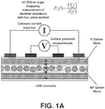
- FIG. 1A shown is a schematic representation of the electrical resistance change method for CFRP composite characterization.
- EIS Electrical impedance spectroscopy
- FIG. 1B a schematic diagram of the impedance measurement in electrical impedance spectroscopy (EIS) is shown.
- EIS has been used in noninvasive material characterization of different composite materials including fiber-reinforced polymers.
- EIS has also been found to be useful in monitoring the cure of plastics during their manufacturing process.
- CFRP composites have been characterized by EIS.
- EIT Electrical impedance tomography
- ⁇ domain boundary
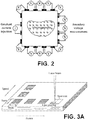
- FIG. 2 shown is a schematic diagram of boundary data collection in electrical impedance tomography (EIT).
- EIT is a low-cost, non-invasive and non-ionizing imaging technique. It has been used in medical diagnosis, industrial process tomography, civil engineering, geotechnology, material engineering, and biotechnology.
- Laminates were obtained from carbon fiber prepregs made of a toughened epoxy resin supplied by Hexcel Composites (HexPly M21 / 35% / 268 / T700GC). The resin and fiber densities were 1.28 g/cm 3 and 1.80 g/cm 3 , respectively, and the nominal fiber volume fraction was 56.9%. Unidirectional ([0] 8 ) and cross-ply laminates ([0°/90°] 2s ) were fabricated by compression molding of the prepreg sheets.
- the following curing cycle was used during fabrication: (1) a full vacuum at 1 bar was applied to the whole stack to avoid air entrapment and the formation of voids; (2) a 7 bar gauge pressure was then applied through a hydraulic hot press machine (e.g., Laboratory Press 15T, PEI France) at 180°C for 120 minutes; and (3) the laminate was cooled down at 2°C/min intervals.
- the obtained composite laminates were used as substrates for the parametric study of the effects of laser processing parameters and for electrical contact resistance measurements.
- Laser irradiation was carried out using, e.g., a ytterbium (Yb) fiber laser (1064 nm wavelength) through a PLS6MW multi-wavelength laser platform (e.g., Universal Laser Systems, USA).
- Yb ytterbium
- PLS6MW multi-wavelength laser platform e.g., Universal Laser Systems, USA.
- the main processing parameters of the system were:
- FIG. 3A shown is a schematic depiction of the electrode array employed to probe the different laser processing configurations.
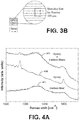
- FIG. 3B illustrates the location of the Raman survey line for each processed surface.
- the quality of the processed surfaces was analyzed using optical microscopy (OM) on a stereomicroscope (e.g., Leica S6D, Germany).
- OM optical microscopy
- SEM high-resolution scanning electron microscope
- the cross-sections of treated samples were studied with an optical microscope (e.g., Leica DM2500 M, Germany).
- epoxy resin e.g., EpoFix, Struers
- Raman spectroscopy was also used to complement the surface analysis with information concerning the chemical composition.
- a Raman spectrometer e.g., LabRAM Aramis, Horiba Scientific Ltd
- DPSS diode-pumped solid-state
- the laser power on the sample surface was fixed at 0.07 mW to avoid the heating effects on the sample.
- a 50X long work distance lens with a numerical aperture (N.A.) of 0.5 was used to focus the laser and collect scattered light. The exposure time on single spot was 100 s.
- FIG. 4A shown is a plot of an example of Raman spectra of carbon fiber (curve 403), epoxy (curve 406) and epoxy+carbon fibers (curve 409).
- pure epoxy is characterized by two peaks at around 1147 cm -1 and 1585 cm -1 .
- carbon fiber is characterized by two broad bands at 1330 cm -1 and 1610 cm -1 .
- the presence of carbon and epoxy together is indicated by three distinct peaks, which combine the peaks of pure carbon fiber and epoxy (1147 cm -1 , 1330 cm -1 and 1610 cm -1 ).
- a spot is classified into three categories: pure carbon fiber, pure epoxy or a mix of the two.
- the Raman scanning was carried out perpendicular to the fibers over a line with a length of 400 ⁇ m.
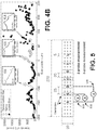
- FIG. 4B shows the line scan and the corresponding Raman spectrum of each point of epoxy (412), epoxy+carbon fibers (415), and carbon fiber (418).
- Electrode fabrication To analyze the contact resistance, six unidirectional composite laminates (270 mm ⁇ 20 mm ⁇ 2 mm) were prepared. Three samples were surface treated using laser irradiation while the remaining three samples were manually sanded. In both cases, the targeted areas for electrode placement were 5 mm ⁇ 20 mm while the spacing between the center points of the areas was 25 mm.
- FIG. 5 shows an example of a configuration of the electrodes on an 8-ply unidirectional (UD) laminate with a schematic of the two-probe and the three-probe methods. Sets of electrodes were fabricated by three different techniques: (i) copper electroplating (ii) copper electroplating with a seed layer and (iii) silver paste.
- Copper electroplating Copper electroplating was performed on the treated surfaces by mainly following the procedures outlined in " Durability Estimates of Copper Plated Electrodes for Self-sensing CFRP Composites" by A. Todoroki et al. (Journal of Solid Mechanics and Materials Engineering 4, pp. 610-620, 2010 ) with the main difference the surface preparation method.
- the substrate surfaces were delineated using vinyl tape such that only the areas allocated for electrode placement (5 mm ⁇ 20 mm) were exposed.
- the taped samples were placed in a copper sulfate (Cu 2 SO 4 ) solution along with a copper plate.
- a low current density (0.66 A/dm 2 ) was then supplied for 120 minutes to obtain an initial uniform thin copper layer over the targeted areas.
- lead wires were bonded to the copper layer with a conductive epoxy adhesive (e.g., ITW Chemtronics, USA). After the adhesive was cured, the sample was again placed in the copper sulfate solution and a higher current density (6 A/dm 2 ) was applied for 90 minutes to fully cover the wires. In this way it was possible to avoid the occurrence of thermal stresses induced by soldering. As a final step, the tape was removed from the sample and a non-conductive epoxy adhesive was applied to cover the electrodes to protect them from environmental conditions and potential damage induced during sample handling.
- a conductive epoxy adhesive e.g., ITW Chemtronics, USA.
- Copper electroplating with a seed layer To improve the growth of the electroplated copper, Todoroki et al. ("Durability Estimates of Copper Plated Electrodes for Self-sensing CFRP Composites," Journal of Solid Mechanics and Materials Engineering 4, pp. 610-620, 2010 ) used silver paste as a seed layer. Here, copper was used as the seed layer through copper deposition of two samples. The samples were covered with a vinyl tape to expose only the areas targeted for the deposition. Afterward, a 1- ⁇ m layer of copper was deposited for 50 minutes using an e-beam evaporator (e.g., Denton Vacuum Inc., USA). The tape was then removed, and new tape was applied for the copper electroplating process during which low current density and high current density baths were used.
- e-beam evaporator e.g., Denton Vacuum Inc., USA
- Silver paste The procedure used to make electrodes using silver paste (e.g., Electron Microscopy Sciences, USA) was carried out as follows. Surface-treated substrates were masked with vinyl tape and then silver paste was applied to the unmasked locations for electrode fabrication. Wires were then bonded to the silver paste by means of a conductive epoxy adhesive. After the adhesive was cured, the mask was removed and the sample was cleaned with acetone. Finally, following the same procedure as the earlier samples, the electrodes were covered with a protective layer of standard epoxy resin.
- Measurements of electrical contact resistance During the electrical measurements, an alternating current of 450 Hz and 30 mA was supplied while the impedance was measured using a LCR meter (e.g., Agilent-E4980A Precision LCR meter). Since the phase angle was negligible, the measured impedance was considered to be equal to the electrical resistance. The electrical resistance measurements were carried out using two-probe and three-probe methods to evaluate the electrical contact resistance of the electrodes.
- the electrical potential (V) was measured via voltage sensor 503 between the same electrodes where the current (A) was injected via current source 506. This was done between the electrode (I 1 ) and the following electrodes (A, B, C, D and E).
- the electrical potential (V) was measured via voltage sensor 503 between two electrodes (e.g., I 1 and A) while the current (A) was injected at two electrodes including one common electrode and another electrode (e.g., I 1 and B) via current source 509. Similarly for the next electrical potential measurement between (I 1 and B), the current injection was at (I 1 and C) and so on.
- the electrical potential of the three-probe measurement was subtracted from that of the two-probe measurement for the same pair of electrodes.
- FIG. 6(a) shows an optical microscopy image (40X mag.) of a sanded surface
- FIGS. 6(b) and 6(c) show SEM images of the indicated portions of the sanded surface.
- the optical and SEM images of sanded surfaces which are shown in FIGS. 6(a) and (b) respectively, demonstrate the unevenness of the obtained surface. Indeed, epoxy residue can be observed around the edges of the treated area. This is because the quality of the surface finish cannot be guaranteed by a manual process. This is one of the main drawbacks of the sanding method as it suffers from operator-to-operator variability.
- FIG. 6(b) is highlighted by the SEM image in FIG. 6(c) , which shows a significant amount of epoxy resin that was not removed from the surface, as well as surface fibers that were damaged during the process. Both drawbacks were systematically observed in all sanded surfaces.
- FIG. 7A shown is an image of an actual cross-sectional view of a sanded surface and a schematic representation of the indicated portion of the sanded surface.
- the schematic representation emphasizes the main attributes of the surface: the non-uniform removal of the surface resin and the induced fiber damage.
- FIG. 7B shows an image of the actual cross-sectional view of a laser treated surface and a schematic representation of the indicated portion of the sanded surface.
- the schematic representation illustrates that the process was able to remove the resin effectively without producing the same fiber damage.
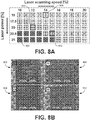
- FIGS. 8A and 8B shown are a graphical representation of the various combinations of laser processing parameters along with optical microscopy observations of selected electrode surfaces that were treated with laser irradiation. Broad classifications of the electrode surfaces of FIG. 8A were determined based on optical pictures. The treated electrode surfaces are grouped into three categories with the following labels: "R" for surfaces with poor surface resin removal; “D” for surfaces with fiber damage; and “I” for surfaces with efficient resin removal. It is apparent from the classification pattern of FIG. 8A that higher laser power/frequency results in high incident energy into the material and that lower laser speed results in higher duration of the local interaction with the material. It follows that increased heat absorption leads to a high local temperature and fiber vaporization. It should be noted that when the surface of the CFRP is subjected to laser irradiation, the energy delivered to the surface is absorbed, thereby exciting the bonds and generating heat.
- FIG. 8B also shows four optical images (10X mag.) of samples taken from selected regions representative of the three categories.
- Image 803 from group "D” shows an example of a surface with fiber damage
- image 806 from group “R” shows an example of a surface with poor resin removal
- images 809 and 812 show examples of surfaces with efficient resin removal.
- FIG. 9 shows SEM images of the four samples from three categories with insets including magnified SEM images.
- FIG. 9(a) shows the surface with extensive fiber damage of image 803;
- FIG. 9(b) shows the surface with minimal surface resin removal of image 806;
- FIGS. 9(c) and 9(d) show the surfaces with efficient resin removal of images 809 and 812, respectively.
- extensive fiber damage occurred in the samples that were exposed to either high laser power, slow laser speed or both. This is because at high power or at low speed, the amount of energy absorbed locally is high enough to induce fiber damage.
- samples processed at high laser speeds or low laser power exhibit poor surface resin removal as the local energy density is not high enough for the surface removal to occur.
- the samples in the intermediate range exhibit effective resin removal with apparent minimal damage.
- the cross-sectional views show that the electrode surface obtained as a result of laser irradiation is rougher than that obtained using sanding.
- High surface roughness is usually attributed to better interlocking with the electrode and can result in better adhesion between the two joining surfaces of the electrode and the laminate.
- laser irradiation can increase the durability of the contact between the electrode and laminate.
- FIG. 10 includes plots illustrating examples of Raman imaging results from a sanded surface and a laser-treated surface.
- a typical response recorded during Raman line scanning over a 400 ⁇ m line of a sanded sample is provided in FIG. 10(a) .
- the intensity counts were distributed as follows: 25% for carbon fibers, 38.5% for pure epoxy and 36.5% for the combination of both. Analysis of these results demonstrated that with sanding, the percentage of fully exposed fibers is very low and that most of fibers are covered with a very thin layer of resin.
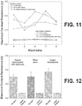
- FIGS. 11 and 12 show electrical contact resistance values of the sanded samples and the laser-treated samples for different electrode materials, respectively.
- FIG. 11 illustrates the electrical contact resistance of the five inner electrodes in different electrode materials.
- the calculated electrical contact resistance of the five inner electrodes (A-E, marked in the abscissa of FIG. 11 ) was based on the difference between the two-probe and three-probe measurements. From the bar chart of FIG. 12 , it can be seen that the electrical contact resistance of the sanded surfaces (average 0.325 ⁇ ) is about five times the electrical contact resistance of the laser-treated surfaces (average 0.067 ⁇ ). Also, FIG.
- FIG. 11 shows that the sanded samples exhibit large variations in the measured contact impedance (around ⁇ 0.06 ⁇ ) thereby indicating low repeatability. In comparison, FIG. 11 shows that the laser-treated samples exhibit high repeatability with a very low variation (around ⁇ 0.01 ⁇ ).
- the sanded samples exhibited variations in the contact impedance depending on the electrode material used. These variations may be attributed to the inhomogeneity in the sanded samples. However, the laser-treated samples exhibited little variation in terms of the electrode material. These results suggest that the contact impedance mainly depends on the method of surface preparation and is independent of the electrode material. This is advantageous as silver paste is superior in terms of scalability, ease of processing and cost when compared to copper plating. Thus, silver paste can be used instead of copper electroplating to prepare the electrodes. Although the durability was not studied, it is believed that the surface roughness obtained through laser irradiation provides improved interlocking and hence greater durability irrespective of the electrode material used.
- Electrodes are a key component of any EIT system and as such they should feature low resistivity as well as high robustness and reproducibility.
- a processing technique for surface preparation of composite laminates based on the use of pulsed laser irradiation has been presented.
- the effect of various laser processing parameters on the morphology of the surfaces was examined.
- the processing parameters that result in selective removal of the electrically insulating resin with minimum surface fiber damage were identified.
- Proper laser parameters with minimal surface fiber damage were obtained.
- the surfaces were characterized using microscopic imaging, SEM and Raman spectrum mapping. The results showed that the electrical contact resistance of the sanded samples (average 0.325 D) is about five times the electrical contact resistance of the laser-treated surfaces (average 0.067 ⁇ ).
- ratios, concentrations, amounts, and other numerical data may be expressed herein in a range format. It is to be understood that such a range format is used for convenience and brevity, and thus, should be interpreted in a flexible manner to include not only the numerical values explicitly recited as the limits of the range, but also to include all the individual numerical values or sub-ranges encompassed within that range as if each numerical value and sub-range is explicitly recited.
- a concentration range of "about 0.1 % to about 5%” should be interpreted to include not only the explicitly recited concentration of about 0.1 wt% to about 5 wt%, but also include individual concentrations ( e.g., 1%, 2%, 3%, and 4%) and the sub-ranges ( e.g ., 0.5%, 1.1%, 2.2%, 3.3%, and 4.4%) within the indicated range.
- the term “about” can include traditional rounding according to significant figures of numerical values.
- the phrase "about 'x' to 'y'" includes “about 'x' to about 'y"'.
Landscapes
- Physics & Mathematics (AREA)
- Chemical & Material Sciences (AREA)
- Engineering & Computer Science (AREA)
- Health & Medical Sciences (AREA)
- Biochemistry (AREA)
- Immunology (AREA)
- Pathology (AREA)
- Life Sciences & Earth Sciences (AREA)
- General Physics & Mathematics (AREA)
- Analytical Chemistry (AREA)
- General Health & Medical Sciences (AREA)
- Optics & Photonics (AREA)
- Plasma & Fusion (AREA)
- Mechanical Engineering (AREA)
- Spectroscopy & Molecular Physics (AREA)
- Chemical Kinetics & Catalysis (AREA)
- Electrochemistry (AREA)
- Nuclear Medicine, Radiotherapy & Molecular Imaging (AREA)
- Investigating, Analyzing Materials By Fluorescence Or Luminescence (AREA)
- Inorganic Fibers (AREA)
- Reinforced Plastic Materials (AREA)
Description
- In recent times the use of modern composite materials is becoming increasingly widespread. However, the failure modes of composite structures are extremely complex and, unlike metals, they may suffer significant degradation with barely visible surface damage. Since the damage may cause serious decrease in material strength and lead to catastrophic failure, the development of reliable structural health monitoring (SHM) techniques can have a tremendous impact on the life-cycle cost spent for inspection and repair.
- As a result, a number of nondestructive evaluation techniques have been put forward, including dielectric spectroscopy, ultrasonic evaluation, vibration analysis, phased array analysis, shearography, thermography, infrared thermography, ultrasonic phased array, sampling phased array (SPA), synthetic aperture focusing technique (SAFT), flash thermography, dynamic modulus measurements, and acoustic emission monitoring.
- The paper "An Investigation of Contact Resistance Between Carbon Fiber/Epoxy Composite Laminate and Printed Silver Electrode for Damage Monitoring" by Eun-Beom Jeon et al. discloses using fine grade sand paper to pretreat a target area on a carbon fiber reinforced polymer (CFRP) composite surface. Sanding is a manual technique dependent on the operator, which leads to non-repeatable results. It is also time consuming and may induce damage on the exposed surface of the laminate.
- The paper "Laser Surface Pre-Treatment of CFRP for Adhesive Bonding in Consideration of the Absorption Behaviour" by F. Fischer et al., discloses using laser pretreatment of areas of a CFRP composite surface to enhance bonding of a component to the surface.
- The invention is set out in the claims. The present disclosure is related to the preparation of electrodes on carbon fiber reinforced polymer (CFRP) composites with low contact resistance. The method comprises preparing a pretreated target area on a carbon fiber reinforced polymer (CFRP) composite surface using laser pulsed irradiation; and bonding an electrode to exposed fibers in the pretreated target area.
- The electrode exhibits a low contact resistance with the CFRP composite. The electrode can have a contact resistance of about 0.1 ohms or less. The electrode can exhibit a uniform bonding over the pretreated target area.
- In one or more aspects of these embodiments, the method can comprise preparing a plurality of pretreatment target areas on the CFRP composite surface using laser pulsed irradiation; and bonding a plurality of electrodes to corresponding ones of the plurality of pretreatment target areas. Individual electrodes of the plurality of electrodes can have a contact resistance of about 0.1 ohms or less. The plurality of electrodes can exhibit an average contact resistance of about 0.07 ohms or less. The plurality of electrodes can exhibit a repeatable contact resistance. Variation of the contact resistance of the plurality of electrodes can be about ± 0.01 ohm or less. In one or more aspects of these embodiments, about 75% or more of exposed carbon fibers in the pretreated target area of the CRFP composite can be fully exposed by the laser pulsed irradiation. Exposure of the carbon fibers can be evaluated using Raman mapping of the pretreated target area. The electrode can be mechanically interlocked with fully exposed fibers in the pretreated target area during bonding.
- In one or more aspects of these embodiments, bonding the electrode can comprise applying silver paste to the pretreated target area. The method comprises positioning the CFRP composite surface for pretreatment of a target area of the CFRP surface; preparing the pretreated target area by irradiation with a pulsed laser along a series of paths in the target area; and bonding the electrode to exposed carbon fiber in the pretreated target area. The series of paths are a plurality of parallel paths. The pulsed laser can have a focused beam diameter (ds ) of 25 µm on the CFRP surface. The series of paths have a minimum line spacing (p) of 30 µm. The pulsed laser has a frequency (f) of 30 kHz and can traverse the series of paths at a scanning speed (v) of less than or equal to 500 mm/second, and with an average power (Pave ) of the laser that is less than or equal to 30 Watts.
- In one or more aspects of these embodiments, the scanning speed (v) can be less than 100 mm/second and the average power (Pave ) of the laser can be equal to or less than 7.5 Watts. The scanning speed (v) can be equal to or greater than 50 mm/second and the average power (Pave ) of the laser can be greater than 4.5 Watts. The average power (Pave ) of the laser can be greater than 6.75 Watts when the scanning speed (v) is greater than 75 mm/second and the average power (Pave ) of the laser can be equal to or less than 6.75 Watts when the scanning speed (v) is equal to or less than 75 mm/second. The average power (Pave ) of the laser can be greater than 5.25 Watts when the scanning speed (v) is equal to or greater than 60 mm/second. A pulse duration (τp ) of the pulsed laser can be greater or equal to 10 nanoseconds.
- Many aspects of the present disclosure can be better understood with reference to the following drawings. The components in the drawings are not necessarily to scale, emphasis instead being placed upon clearly illustrating the principles of the present disclosure. Moreover, in the drawings, like reference numerals designate corresponding parts throughout the several views.
-
FIGS. 1A and1B are schematic diagrams illustrating examples of electrical resistance change method (ERCM) and electrical impedance spectroscopy (EIS), respectively, for composite characterization. -
FIG. 2 is a schematic diagram illustrating an example of electrical impedance tomography (EIT) for composite characterization. -
FIGS. 3A and3B illustrate preparation and characterization of a surface of a carbon fiber reinforced polymer (CFRP) composite, in accordance with the present disclosure. -
FIGS. 4A and4B are plots illustrating examples of Raman spectra and line scans of various substrate surfaces. -
FIG. 5 illustrates two-probe and the three-probe methods for electrical measurements of prepared CFRP surfaces. -
FIG. 6 includes images of a sanded surface. -
FIGS. 7A and 7B include images and graphical representations comparing sanded and laser-treated surface preparations, in accordance with the present disclosure. -
FIGS. 8A and 8B illustrate classifications of laser-treated surfaces in accordance with the present disclosure. -
FIG. 9 includes high resolution images of examples of laser-treated surfaces according to the classifications given inFIGS. 8A and 8B , in accordance with the present disclosure. -
FIG. 10 includes plots illustrating examples of Raman imaging results from a sanded surface and a laser-treated surface, in accordance with the present disclosure. -
FIGS. 11 and 12 illustrate electrical contact resistance values of sanded and the laser-treated surfaces, in accordance with the present disclosure. - Disclosed herein are various examples related to laser-based surface preparation for bonding to carbon fiber reinforced polymer composites. Reference will now be made in detail to the description of the examples as illustrated in the drawings, wherein like reference numbers indicate like parts throughout the several views.
- Structural health monitoring is an inspection need for any structure in service. Carbon fiber reinforced polymer (CFRP) composites have the advantage that they do not need external sensors to monitor the structure in terms of electrical measurements. Instead, the carbon fibers are the sensors inside the CFRP structures. Due to the processing of such composite, there is a rich resin layer formed on the external surface of the structure to be monitored. The monitoring is done by bonding electrodes on the surface of the structure where such electrodes should feature low resistivity, as well as high robustness and reproducibility.
- Techniques based on changes in electrical properties (i.e. electrical resistance or impedance methods) offer fast and low-cost methods that are suitable for offline or online inspection of CFRP composites. Electrical impedance tomography (EIT) can be non-invasive and used for in-situ and real-time monitoring of structural integrity in terms of electrical impedance. Unlike other classical methods, such as optical fiber grating, ultrasonic, acoustic emission, and modal analysis, EIT does not need highly sensitive external sensors and/or actuators or costly equipment.
- One of the main components of an EIT system is the electrode array which acts as an interface between the external hardware and the structure. To monitor structural health, a constant current can be supplied through a set of electrodes and then electric potentials can be collected from subsequent pairs of electrodes. Variations in electric potential profiles obtained from the two measurement cycles can be used to reconstruct the corresponding variation of conductivity in the domain of interest. The obtained conductivity image can then be used to assess the type and extent of local damage in the tested volume provided the relationships between the damage level and the (generally anisotropic) local change in conductivity are known. This task can be accomplished through the solution of an inverse problem and the corresponding relationships. It follows that the outcome of the reconstruction process depends on the robustness of the system and the accuracy of the data which, in turn, rely on the quality of the interface between the electrical hardware (e.g., the electrodes) and the structure being monitored.
- A high-quality electrode should possess the following characteristics: (i) the interfacial bonding should be strong and uniform; (ii) the contact impedance should be low; (iii) the electrode material should be highly conductive; (iv) the durability of the electrode should be long term, i.e. the electrode should not debond with time/load so that the electrical resistance of the interface can be considered low, uniform and stable over the time; (v) the fabrication steps should be easy to reproduce; and (vi) the coupling of the electrode to the laminate should not induce any damage or create a hot spot in the structure. Additional factors that have implications that may be important, in terms of both processing and practice, include the electrode's low cost and easy mass production with minimal manual intervention. Here, electrodes used for EIT of composite laminates can be obtained in four main steps: (1) surface preparation, (2) bonding of the electrode to the structure, (3) electrical wiring and (4) coating with an insulating and protective material.
- Surface preparation and bonding are the most important steps. Surface preparation involves removal of the surface resin to expose the conductive carbon fibers to which the highly conductive electrode material will be bonded. This step is important because the main conducting elements in a CFRP composite are often the carbon fibers, which are connected to the electrodes. Materials commonly used in electrodes include silver paste, copper, carbon cement or graphite, and several routines have been devised to apply the electrodes to the target surface, including electroplating, painting, sputtering and printing. Copper electroplating can have high repeatability and durability but the method needs uniform removal of the surface resin. Indeed, weaker adhesion forces often develop at the copper/resin interface, which can lead to debonding and malfunctioning. Moreover, since the current flows only through the carbon fibers that are in contact with the electrode, large zones of unpolished surface resin can lead to non-homogeneous current flow through the material. Proper surface preparation can improve the quality of the output from the electrodes.
- Surface preparation is usually accomplished by sanding, which involves manual removal of the resin layer through the use of several grades of sand paper. The limitations of sanding include that it is a manual technique that is dependent on the operator and which leads to non-repeatable results. In addition, it is also time consuming and may induce damage on the exposed surface of the laminate. Therefore, alternative techniques may be used to overcome these limitations. From this standpoint, pulsed laser irradiation can be a very effective surface modification technique for a variety of materials. For instance, it can be used to improve adhesion between metals and epoxy resin, but may also be used for precision material cutting and/or drilling on a variety of materials including composites.
- With carefully selected processing parameters (e.g., laser wavelength, average power delivered by the laser beam, pulse duration and frequency, laser scanning speed), laser irradiation can be used to remove material through photochemical (photolytic) or photothermal (pyrolytic) processes or a combination of both. In photochemical ablation, the bond excitation above a certain limit induces material dissociation. This process is characteristic of lasers with short wavelengths, such as UV lasers. At longer wavelengths, the applied energy is not high enough to induce the photolytic process and hence is absorbed into the material as vibrational energy or heat. When the temperature reaches the vaporization temperature of the material, the material evaporates or sublimates. Extensive surface modifications occur when the applied energy reaches a certain threshold, which depends on the target material as well as the selected laser processing parameters. In the case of CFRP, the properties of the primary constituents vary dramatically. The laser's parameters thus can be carefully tuned to selectively remove the polymer matrix with little or no fiber damage.
- Laser irradiation can be used in place of sanding, in the preparation of high-quality electrodes for EIT. In particular, suitable laser processing parameters can be identified that allow the selective removal of surface resin with negligible fiber damage. The quality of the electrodes prepared using laser irradiation and sanding can be compared in terms of electrode/substrate contact resistance. A short review of EIT and electrical monitoring of CFRP is provided in this disclosure, followed by experimental investigations including the protocols to fabricate and test the different types of electrodes. The results include both a detailed morphological analysis of the surface (to assess the removal of the resin from the prepared surface) and an evaluation of the electrical resistance of the tested electrodes.
- Three methods may be used for CFRP composite characterization: electrical resistance change method (ERCM), electrical impedance spectroscopy (EIS) and electrical impedance tomography (EIT). The electrical resistance change in carbon fiber reinforced polymers (CFRP) is useful in monitoring damage initiation. Many researchers have utilized the electrical resistance change method to detect damage in CFRP composites. ERCM applies a DC or AC current with constant amplitude at a particular frequency and measures the surface potential to calculate the resistance of the material using four electrodes. Referring to
FIG. 1A , shown is a schematic representation of the electrical resistance change method for CFRP composite characterization. - Electrical impedance spectroscopy (EIS) measures electrical impedance of the CFRP part from the voltage-current data collected at the object boundary at different signal frequencies (f). Referring to
FIG. 1B , a schematic diagram of the impedance measurement in electrical impedance spectroscopy (EIS) is shown. A constant amplitude sinusoidal electrical current is injected at different frequencies to identify the change in frequency of the impedance (Z) of the sample. EIS has been used in noninvasive material characterization of different composite materials including fiber-reinforced polymers. EIS has also been found to be useful in monitoring the cure of plastics during their manufacturing process. CFRP composites have been characterized by EIS. - Electrical impedance tomography (EIT) is a computed tomographic technique that provides 2D or 3D reconstructions of the spatial distribution of the electrical properties of a domain (Ω). It relies on voltage-current data measured at the domain boundary (∂Ω), which is mapped by an array of electrodes. Referring to
FIG. 2 , shown is a schematic diagram of boundary data collection in electrical impedance tomography (EIT). EIT is a low-cost, non-invasive and non-ionizing imaging technique. It has been used in medical diagnosis, industrial process tomography, civil engineering, geotechnology, material engineering, and biotechnology. - In ERCM, EIS and EIT, voltage-current data are used to obtain the resistance or impedance parameters of the composite structure, and hence an array of sensors or electrodes is placed on the material's surface to create an interface between the material and the instrumentation system. Because CFRP materials are composed of conducting carbon fibers embedded in an insulating resin, the placement of electrodes on a CFRP surface is not only a difficult task but it also plays a significant role in the accuracy of the measurements, the quality of the data and all final results. Here, an electrode fabrication method that facilitates the placement and connection of the electrodes on CFRP composite materials in ERCM, EIS, EIT or any other resistance (or impedance) analyzing techniques is disclosed.
- Fabrication of composite laminates. Laminates were obtained from carbon fiber prepregs made of a toughened epoxy resin supplied by Hexcel Composites (HexPly M21 / 35% / 268 / T700GC). The resin and fiber densities were 1.28 g/cm3 and 1.80 g/cm3, respectively, and the nominal fiber volume fraction was 56.9%. Unidirectional ([0]8) and cross-ply laminates ([0°/90°]2s) were fabricated by compression molding of the prepreg sheets. The following curing cycle was used during fabrication: (1) a full vacuum at 1 bar was applied to the whole stack to avoid air entrapment and the formation of voids; (2) a 7 bar gauge pressure was then applied through a hydraulic hot press machine (e.g., Laboratory Press 15T, PEI France) at 180°C for 120 minutes; and (3) the laminate was cooled down at 2°C/min intervals. The obtained composite laminates were used as substrates for the parametric study of the effects of laser processing parameters and for electrical contact resistance measurements.
- Surface pretreatment. Laser irradiation was carried out using, e.g., a ytterbium (Yb) fiber laser (1064 nm wavelength) through a PLS6MW multi-wavelength laser platform (e.g., Universal Laser Systems, USA). The main processing parameters of the system were:
- laser maximum average power (Pave ) of 30 W;
- pulse frequency (f) of 30 kHz;
- pulse duration (τp ) ≥ 10 ns;
- minimum line spacing (p) of 30 µm;
- maximum scanning speed (v) of 500 mm/s; and
- focused beam diameter (ds ) of 25 µm.
- In the subsequent experiments, selected values of the average power and laser scanning speed were specified as percentages of the maximum values allowed by the system. To finely tune the laser irradiation, the power was varied within 15% - 25% of the maximum average power by steps of 2.5% while the laser speed was varied between 10% - 20% of the maximum speed by steps of 1 %. This range was narrowed based on the results of preliminary experiments carried out in wider power and speed ranges. For this parametric study, (5 mm × 5 mm) square arrays were processed on a cross-ply substrate by varying the laser's power and speed, giving rise to fifty-five combinations of (Pave, V). Referring to
FIG. 3A , shown is a schematic depiction of the electrode array employed to probe the different laser processing configurations.FIG. 3B illustrates the location of the Raman survey line for each processed surface. These preliminary tests were used to select the optimal combination of laser processing parameters in the fiber direction to achieve uniform surface resin removal and limited fiber damage. Subsequently, these laser parameters were replicated onto 5 mm × 20 mm rectangular areas allocated for electrode fabrication. - For comparison, the sanding procedure outlined in "Durability Estimates of Copper Plated Electrodes for Self-sensing CFRP Composites" by A. Todoroki et al. (Journal of Solid Mechanics and Materials Engineering 4, pp. 610-620, 2010) was followed. In particular, 5 mm × 20 mm areas were delimited using surface masking with vinyl tape. Note that contrary to laser preparation, precise control of the treated area was not possible, and for this reason masking was carried out beforehand. The areas were then treated with two grades of sand paper (e.g., SiC-
paper grit 320 and 1000, Struers). The sanding was carried out parallel to the fibers direction. A few drops of concentrated sulfuric acid (97%) were then applied to complete the process, followed by extensive cleaning with distilled water and acetone. - Survey of surface morphology and chemistry. The quality of the processed surfaces was analyzed using optical microscopy (OM) on a stereomicroscope (e.g., Leica S6D, Germany). In addition, a high-resolution scanning electron microscope (SEM) was used to analyze the surfaces (e.g., FEI Quanta 200). The cross-sections of treated samples were studied with an optical microscope (e.g., Leica DM2500 M, Germany). To prepare the cross-sections, samples were embedded in epoxy resin (e.g., EpoFix, Struers) and, after curing, they were cut and polished to enhance imaging.
- Since optical and scanning microscopy deliver only qualitative assessments of the treated surfaces, Raman spectroscopy was also used to complement the surface analysis with information concerning the chemical composition. A Raman spectrometer (e.g., LabRAM Aramis, Horiba Scientific Ltd) was used to probe the samples in the range of 1000 -1700 cm-1. A diode-pumped solid-state (DPSS) laser with a wavelength of 785 nm was used as the excitation source (low photon energy was needed to avoid excessive fluorescence of the resin). The laser power on the sample surface was fixed at 0.07 mW to avoid the heating effects on the sample. A 50X long work distance lens with a numerical aperture (N.A.) of 0.5 was used to focus the laser and collect scattered light. The exposure time on single spot was 100 s.
- Referring to
FIG. 4A , shown is a plot of an example of Raman spectra of carbon fiber (curve 403), epoxy (curve 406) and epoxy+carbon fibers (curve 409). As shown inFIG. 4A , pure epoxy is characterized by two peaks at around 1147 cm-1 and 1585 cm-1. Similarly, carbon fiber is characterized by two broad bands at 1330 cm-1 and 1610 cm-1. The presence of carbon and epoxy together is indicated by three distinct peaks, which combine the peaks of pure carbon fiber and epoxy (1147 cm-1, 1330 cm-1 and 1610 cm-1). Depending on the location and number of peaks, a spot is classified into three categories: pure carbon fiber, pure epoxy or a mix of the two. The Raman scanning was carried out perpendicular to the fibers over a line with a length of 400 µm. - The samples were mounted on a 3D automatic stage for the line-scan Raman measurements. The stage was displaced automatically along the selected line on the sample surface while the spectrometer recorded the Raman spectrum for each collection point. Each collection point had a spot size of 2 µm in diameter and the sample stage moved 2 µm, thereby resulting in 200 acquisition points along the selected scanning line. Raman scanning provides quantitative results about the surface quality in terms of fiber exposure.
FIG. 4B shows the line scan and the corresponding Raman spectrum of each point of epoxy (412), epoxy+carbon fibers (415), and carbon fiber (418). - Electrode fabrication. To analyze the contact resistance, six unidirectional composite laminates (270 mm × 20 mm × 2 mm) were prepared. Three samples were surface treated using laser irradiation while the remaining three samples were manually sanded. In both cases, the targeted areas for electrode placement were 5 mm × 20 mm while the spacing between the center points of the areas was 25 mm.
FIG. 5 shows an example of a configuration of the electrodes on an 8-ply unidirectional (UD) laminate with a schematic of the two-probe and the three-probe methods. Sets of electrodes were fabricated by three different techniques: (i) copper electroplating (ii) copper electroplating with a seed layer and (iii) silver paste. - Copper electroplating. Copper electroplating was performed on the treated surfaces by mainly following the procedures outlined in "Durability Estimates of Copper Plated Electrodes for Self-sensing CFRP Composites" by A. Todoroki et al. (Journal of Solid Mechanics and Materials Engineering 4, pp. 610-620, 2010) with the main difference the surface preparation method. The substrate surfaces were delineated using vinyl tape such that only the areas allocated for electrode placement (5 mm × 20 mm) were exposed. The taped samples were placed in a copper sulfate (Cu2SO4) solution along with a copper plate. A low current density (0.66 A/dm2) was then supplied for 120 minutes to obtain an initial uniform thin copper layer over the targeted areas. After that, lead wires were bonded to the copper layer with a conductive epoxy adhesive (e.g., ITW Chemtronics, USA). After the adhesive was cured, the sample was again placed in the copper sulfate solution and a higher current density (6 A/dm2) was applied for 90 minutes to fully cover the wires. In this way it was possible to avoid the occurrence of thermal stresses induced by soldering. As a final step, the tape was removed from the sample and a non-conductive epoxy adhesive was applied to cover the electrodes to protect them from environmental conditions and potential damage induced during sample handling.
- Copper electroplating with a seed layer. To improve the growth of the electroplated copper, Todoroki et al. ("Durability Estimates of Copper Plated Electrodes for Self-sensing CFRP Composites," Journal of Solid Mechanics and Materials Engineering 4, pp. 610-620, 2010) used silver paste as a seed layer. Here, copper was used as the seed layer through copper deposition of two samples. The samples were covered with a vinyl tape to expose only the areas targeted for the deposition. Afterward, a 1-µm layer of copper was deposited for 50 minutes using an e-beam evaporator (e.g., Denton Vacuum Inc., USA). The tape was then removed, and new tape was applied for the copper electroplating process during which low current density and high current density baths were used.
- Silver paste. The procedure used to make electrodes using silver paste (e.g., Electron Microscopy Sciences, USA) was carried out as follows. Surface-treated substrates were masked with vinyl tape and then silver paste was applied to the unmasked locations for electrode fabrication. Wires were then bonded to the silver paste by means of a conductive epoxy adhesive. After the adhesive was cured, the mask was removed and the sample was cleaned with acetone. Finally, following the same procedure as the earlier samples, the electrodes were covered with a protective layer of standard epoxy resin.
- Measurements of electrical contact resistance. During the electrical measurements, an alternating current of 450 Hz and 30 mA was supplied while the impedance was measured using a LCR meter (e.g., Agilent-E4980A Precision LCR meter). Since the phase angle was negligible, the measured impedance was considered to be equal to the electrical resistance. The electrical resistance measurements were carried out using two-probe and three-probe methods to evaluate the electrical contact resistance of the electrodes.
- In the two-probe method shown in
FIG.5 , the electrical potential (V) was measured viavoltage sensor 503 between the same electrodes where the current (A) was injected viacurrent source 506. This was done between the electrode (I1) and the following electrodes (A, B, C, D and E). - In the three-probe method shown in
FIG. 5 , the electrical potential (V) was measured viavoltage sensor 503 between two electrodes (e.g., I1 and A) while the current (A) was injected at two electrodes including one common electrode and another electrode (e.g., I1 and B) viacurrent source 509. Similarly for the next electrical potential measurement between (I1 and B), the current injection was at (I1 and C) and so on. To evaluate the electrical contact resistance of the electrodes (A-E), the electrical potential of the three-probe measurement was subtracted from that of the two-probe measurement for the same pair of electrodes. - Assessment of modifications in the surface morphology.
FIG. 6(a) shows an optical microscopy image (40X mag.) of a sanded surface andFIGS. 6(b) and 6(c) show SEM images of the indicated portions of the sanded surface. The optical and SEM images of sanded surfaces, which are shown inFIGS. 6(a) and (b) respectively, demonstrate the unevenness of the obtained surface. Indeed, epoxy residue can be observed around the edges of the treated area. This is because the quality of the surface finish cannot be guaranteed by a manual process. This is one of the main drawbacks of the sanding method as it suffers from operator-to-operator variability. The uneven finish in the indicated portion ofFIG. 6(b) is highlighted by the SEM image inFIG. 6(c) , which shows a significant amount of epoxy resin that was not removed from the surface, as well as surface fibers that were damaged during the process. Both drawbacks were systematically observed in all sanded surfaces. - Referring now to
FIG. 7A , shown is an image of an actual cross-sectional view of a sanded surface and a schematic representation of the indicated portion of the sanded surface. The schematic representation emphasizes the main attributes of the surface: the non-uniform removal of the surface resin and the induced fiber damage. For comparison,FIG. 7B shows an image of the actual cross-sectional view of a laser treated surface and a schematic representation of the indicated portion of the sanded surface. The schematic representation illustrates that the process was able to remove the resin effectively without producing the same fiber damage. - Referring next to
FIGS. 8A and 8B , shown are a graphical representation of the various combinations of laser processing parameters along with optical microscopy observations of selected electrode surfaces that were treated with laser irradiation. Broad classifications of the electrode surfaces ofFIG. 8A were determined based on optical pictures. The treated electrode surfaces are grouped into three categories with the following labels: "R" for surfaces with poor surface resin removal; "D" for surfaces with fiber damage; and "I" for surfaces with efficient resin removal. It is apparent from the classification pattern ofFIG. 8A that higher laser power/frequency results in high incident energy into the material and that lower laser speed results in higher duration of the local interaction with the material. It follows that increased heat absorption leads to a high local temperature and fiber vaporization. It should be noted that when the surface of the CFRP is subjected to laser irradiation, the energy delivered to the surface is absorbed, thereby exciting the bonds and generating heat. - Since the carbon fibers are thermally more conductive than the polymer matrix, the absorbed heat conducts along the fibers, increasing the temperature locally along the direction of the fibers. Once the temperature reaches the vaporization temperature of the matrix, the matrix along the conduction path evaporates. This zone where the matrix loss occurs due to photo-thermal conduction is known as the heat-affected zone (HAZ). The size of the HAZ depends on the laser scanning speed, direction, power and frequency as these variables determine the energy absorbed into the material.
FIG. 8B also shows four optical images (10X mag.) of samples taken from selected regions representative of the three categories.Image 803 from group "D" shows an example of a surface with fiber damage,image 806 from group "R" shows an example of a surface with poor resin removal, andimages -
FIG. 9 shows SEM images of the four samples from three categories with insets including magnified SEM images.FIG. 9(a) shows the surface with extensive fiber damage ofimage 803;FIG. 9(b) shows the surface with minimal surface resin removal ofimage 806; andFIGS. 9(c) and 9(d) show the surfaces with efficient resin removal ofimages - Referring back to
FIGS. 7A and 7B , the cross-sectional views show that the electrode surface obtained as a result of laser irradiation is rougher than that obtained using sanding. High surface roughness is usually attributed to better interlocking with the electrode and can result in better adhesion between the two joining surfaces of the electrode and the laminate. Thus, laser irradiation can increase the durability of the contact between the electrode and laminate. - Analysis of the surface chemistry using Raman spectroscopy.
FIG. 10 includes plots illustrating examples of Raman imaging results from a sanded surface and a laser-treated surface. A typical response recorded during Raman line scanning over a 400 µm line of a sanded sample is provided inFIG. 10(a) . The intensity counts were distributed as follows: 25% for carbon fibers, 38.5% for pure epoxy and 36.5% for the combination of both. Analysis of these results demonstrated that with sanding, the percentage of fully exposed fibers is very low and that most of fibers are covered with a very thin layer of resin. - Raman line scanning was also carried out on the laser-treated samples from the three categories. Here, the results obtained from line scanning over a 400 µm line of the sample prepared at V = 15% and Pave = 22.5% are shown in
FIG. 10(b) . Note that samples from category "I" exhibited similar results whereas results from category "R" exhibited a very low percentage of exposed fibers. The intensity counts were distributed as follows: 77.5% for fully exposed carbon fibers, 9% for pure epoxy and 13.5% for the combination of both. Therefore, a remarkable improvement in the percentage of fully exposed carbon fibers compared with sanded samples was achieved. There were still areas where the carbon fibers were not completely exposed, which is also captured in the SEM images ofFig. 9(d) , but the percentage was very low in comparison to the number of fully exposed fibers. It is believed that the obtained fiber exposure is sufficient for the purposes of the study. Hence, the combination of the parameters in the intermediate range can be selected as the optimal range. For subsequent electrode fabrication, the combination of V=15% and P=22.5% was chosen. - Analysis of electrical contact resistance.
FIGS. 11 and 12 show electrical contact resistance values of the sanded samples and the laser-treated samples for different electrode materials, respectively.FIG. 11 illustrates the electrical contact resistance of the five inner electrodes in different electrode materials. The calculated electrical contact resistance of the five inner electrodes (A-E, marked in the abscissa ofFIG. 11 ) was based on the difference between the two-probe and three-probe measurements. From the bar chart ofFIG. 12 , it can be seen that the electrical contact resistance of the sanded surfaces (average 0.325 Ω) is about five times the electrical contact resistance of the laser-treated surfaces (average 0.067 Ω). Also,FIG. 11 shows that the sanded samples exhibit large variations in the measured contact impedance (around ± 0.06 Ω) thereby indicating low repeatability. In comparison,FIG. 11 shows that the laser-treated samples exhibit high repeatability with a very low variation (around ± 0.01 Ω). - The sanded samples exhibited variations in the contact impedance depending on the electrode material used. These variations may be attributed to the inhomogeneity in the sanded samples. However, the laser-treated samples exhibited little variation in terms of the electrode material. These results suggest that the contact impedance mainly depends on the method of surface preparation and is independent of the electrode material. This is advantageous as silver paste is superior in terms of scalability, ease of processing and cost when compared to copper plating. Thus, silver paste can be used instead of copper electroplating to prepare the electrodes. Although the durability was not studied, it is believed that the surface roughness obtained through laser irradiation provides improved interlocking and hence greater durability irrespective of the electrode material used.
- Electrodes are a key component of any EIT system and as such they should feature low resistivity as well as high robustness and reproducibility. Here, a processing technique for surface preparation of composite laminates based on the use of pulsed laser irradiation has been presented. In particular, the effect of various laser processing parameters on the morphology of the surfaces was examined. In turn, the processing parameters that result in selective removal of the electrically insulating resin with minimum surface fiber damage were identified. Proper laser parameters with minimal surface fiber damage were obtained. The surfaces were characterized using microscopic imaging, SEM and Raman spectrum mapping. The results showed that the electrical contact resistance of the sanded samples (average 0.325 D) is about five times the electrical contact resistance of the laser-treated surfaces (average 0.067 Ω). All the electrode materials had very low and almost the same electrical contact resistance measurements in the laser-treated samples. Quantitative analysis of the electrical contact resistance were compared with those obtained using sanding. The variation in electrical contact resistance measurements of the laser-treated samples was very low when compared with that of the sanded samples.
- It should be emphasized that the above-described embodiments of the present disclosure are merely possible examples of implementations set forth for a clear understanding of the principles of the disclosure. Many variations and modifications may be made to the above-described embodiment(s) without departing substantially from the spirit and principles of the disclosure. All such modifications and variations are intended to be included herein within the scope of this disclosure and protected by the following claims.
- It should be noted that ratios, concentrations, amounts, and other numerical data may be expressed herein in a range format. It is to be understood that such a range format is used for convenience and brevity, and thus, should be interpreted in a flexible manner to include not only the numerical values explicitly recited as the limits of the range, but also to include all the individual numerical values or sub-ranges encompassed within that range as if each numerical value and sub-range is explicitly recited. To illustrate, a concentration range of "about 0.1 % to about 5%" should be interpreted to include not only the explicitly recited concentration of about 0.1 wt% to about 5 wt%, but also include individual concentrations (e.g., 1%, 2%, 3%, and 4%) and the sub-ranges (e.g., 0.5%, 1.1%, 2.2%, 3.3%, and 4.4%) within the indicated range. The term "about" can include traditional rounding according to significant figures of numerical values. In addition, the phrase "about 'x' to 'y'" includes "about 'x' to about 'y"'.

Claims (11)
- A method, comprising:positioning a carbon fiber reinforced polymer, CFRP, composite surface for pretreatment of a target area of the CFRP surface, wherein the CFRP composite includes a polymer matrix and carbon fibers;preparing a pretreated target area on the CFRP composite surface using laser pulsed irradiation along a series of parallel paths in the target area; andbonding an electrode to exposed fibers in the pretreated target area, wherein the series of paths have a minimum line spacing (p) of 30 µm,characterized in thatenergy of the laser pulsed irradiation delivered to the CFRP composite surface is absorbed to excite bonds and generate heat so that heat absorbed by the CFRP composite surface conducts along the carbon fibers to increase temperature locally along a direction of the carbon fibers and the polymer matrix evaporates or sublimates, andthe pulsed laser has a pulse frequency (f) of 30 kHz and traverses the series of paths at a scanning speed (v) of less than or equal to 500 mm/second, and with an average power (Pave ) of the laser that is less than or equal to 30 Watts.
- The method of claim 1, wherein the electrode has a contact resistance of 0.1 ohms or less.
- The method of claim 1, comprising:preparing a plurality of pretreatment target areas on the CFRP composite surface using laser pulsed irradiation; andbonding a plurality of electrodes to corresponding ones of the plurality of pretreatment target areas,wherein the plurality of electrodes exhibit an average contact resistance of 0.07 ohms or less.
- The method of any of claims 1-3, wherein 75% or more of exposed carbon fibers in the pretreated target area of the CRFP composite are fully exposed by the laser pulsed irradiation.
- The method of any of claims 1-4, wherein the electrode is mechanically interlocked with fully exposed fibers in the pretreated target area during bonding.
- The method of claim 1, wherein the pulsed laser has a focused beam diameter (ds ) of 25 µm on the CFRP surface.
- The method of claim 1, wherein the scanning speed (v) is less than 100 mm/second and the average power (Pave ) of the laser is equal to or less than 7.5 Watts.
- The method of any of claims 1 and 7, wherein the scanning speed (v) is equal to or greater than 50 mm/second and the average power (Pave ) of the laser is greater than 4.5 Watts.
- The method of claim 8, wherein the average power (Pave ) of the laser is greater than 6.75 Watts when the scanning speed (v) is greater than 75 mm/second and the average power (Pave ) of the laser is equal to or less than 6.75 Watts when the scanning speed (v) is equal to or less than 75 mm/second.
- The method of any of claims 8 and 9, wherein the average power (Pave ) of the laser is greater than 5.25 Watts when the scanning speed (v) is equal to or greater than 60 mm/second.
- The method of any of claims 1-10, wherein a pulse duration (τp ) of the pulsed laser is greater or equal to 10 nanoseconds.
Applications Claiming Priority (2)
| Application Number | Priority Date | Filing Date | Title |
|---|---|---|---|
| US201562184326P | 2015-06-25 | 2015-06-25 | |
| PCT/IB2016/053781 WO2016207852A1 (en) | 2015-06-25 | 2016-06-24 | Preparation of electrodes on cfrp composites with low contact resistance comprising laser-based surface pre-treatment |
Publications (2)
| Publication Number | Publication Date |
|---|---|
| EP3314231A1 EP3314231A1 (en) | 2018-05-02 |
| EP3314231B1 true EP3314231B1 (en) | 2020-08-05 |
Family
ID=56411830
Family Applications (1)
| Application Number | Title | Priority Date | Filing Date |
|---|---|---|---|
| EP16738871.9A Not-in-force EP3314231B1 (en) | 2015-06-25 | 2016-06-24 | Preparation of electrodes on cfrp composites with low contact resistance comprising laser-based surface pre-treatment |
Country Status (3)
| Country | Link |
|---|---|
| US (1) | US10722984B2 (en) |
| EP (1) | EP3314231B1 (en) |
| WO (1) | WO2016207852A1 (en) |
Families Citing this family (10)
| Publication number | Priority date | Publication date | Assignee | Title |
|---|---|---|---|---|
| US11673352B2 (en) * | 2016-09-20 | 2023-06-13 | United States Of America As Represented By The Administrator Of Nasa | Automated wave guide system for in-process monitoring of carbon fiber reinforced polymer (CFRP) composite laminates with hanning window tone-bursts of center frequencies from 100-225 kHz and 100-350 kHz |
| CN109682859A (en) * | 2019-01-14 | 2019-04-26 | 浙江大学 | The CFRP material lossless detection method and device of capacitive coupling cordless |
| US20220274369A1 (en) * | 2021-03-01 | 2022-09-01 | Government Of The United States, As Represented By The Secretary Of The Air Force | Prepregs and cured composites having improved surfaces and processes of making and methods of using same |
| JP7844992B2 (en) * | 2022-03-31 | 2026-04-14 | コニカミノルタ株式会社 | Electrical characteristic parameter testing device, electrical characteristic parameter testing method, and program |
| WO2024149959A1 (en) * | 2023-01-13 | 2024-07-18 | Touch Sensity | Original measurement pattern for an electrical process tomography system |
| FR3145039A1 (en) * | 2023-01-13 | 2024-07-19 | Touch Sensity | Original measurement pattern for an electrical process tomography system |
| CN118789629A (en) * | 2024-07-10 | 2024-10-18 | 哈尔滨工业大学 | A high aspect ratio hole precision composite machining method for CFRP plates |
| FR3165415A1 (en) | 2024-08-12 | 2026-02-13 | Touch Sensity | Method for monitoring the manufacturing of an organic matrix composite material |
| KR102915264B1 (en) * | 2024-11-13 | 2026-01-23 | 주식회사 셀라메스 | 3d cell electrical impedance measurement device and cell image analysis system including the same |
| CN120551557B (en) * | 2025-06-05 | 2026-03-31 | 深圳市欧米加智能科技有限公司 | A laser welding device for detecting the contact surface of laser welding |
Family Cites Families (3)
| Publication number | Priority date | Publication date | Assignee | Title |
|---|---|---|---|---|
| US8987632B2 (en) * | 2009-10-09 | 2015-03-24 | The United States Of America As Represented By The Administrator Of The National Aeronautics And Space Administration | Modification of surface energy via direct laser ablative surface patterning |
| JP2012122797A (en) * | 2010-12-07 | 2012-06-28 | Sony Corp | Method and device for evaluating oxide semiconductor electrode, and method of manufacturing oxide semiconductor electrode |
| US20180372664A1 (en) * | 2015-07-06 | 2018-12-27 | King Abdullah University Of Science And Technology | Selective laser etching or ablation for fabrication of devices |
-
2016
- 2016-06-24 EP EP16738871.9A patent/EP3314231B1/en not_active Not-in-force
- 2016-06-24 US US15/576,586 patent/US10722984B2/en not_active Expired - Fee Related
- 2016-06-24 WO PCT/IB2016/053781 patent/WO2016207852A1/en not_active Ceased
Non-Patent Citations (1)
| Title |
|---|
| None * |
Also Published As
| Publication number | Publication date |
|---|---|
| EP3314231A1 (en) | 2018-05-02 |
| US10722984B2 (en) | 2020-07-28 |
| US20180169794A1 (en) | 2018-06-21 |
| WO2016207852A1 (en) | 2016-12-29 |
Similar Documents
| Publication | Publication Date | Title |
|---|---|---|
| US10722984B2 (en) | Preparation of electrodes on CFRP composites with low contact resistance comprising laser-based surface pre-treatment | |
| Almuhammadi et al. | Laser-based surface preparation of composite laminates leads to improved electrodes for electrical measurements | |
| Palmieri et al. | Laser ablation surface preparation for adhesive bonding of carbon fiber reinforced epoxy composites | |
| Bauermann et al. | Scanning acoustic microscopy as a non-destructive imaging tool to localize defects inside battery cells | |
| Duchene et al. | A review of non-destructive techniques used for mechanical damage assessment in polymer composites | |
| Cantwell et al. | The significance of damage and defects and their detection in composite materials: a review | |
| Yi et al. | Evaluation of debonding in CFRP-epoxy adhesive single-lap joints using eddy current pulse-compression thermography | |
| Bégué et al. | Laser shock adhesion test (LASAT) of EB-PVD TBCs: towards an industrial application | |
| Ota et al. | Effect of the interfacial nanostructure on the interlaminar fracture toughness and damage mechanisms of directly bonded carbon fiber reinforced thermoplastics and aluminum | |
| WO2019007449A1 (en) | Method for structuring a sub-surface | |
| CN106501315A (en) | The shortening associated hot tomography-based method for detecting of GFRP crack defects and system | |
| KR20200011374A (en) | Method for fabricating a current collector and associated devices | |
| CN107214409B (en) | A real-time monitoring and detection method for penetration forming of electron beam deep penetration welding | |
| Moustakidis et al. | Non-destructive inspection of aircraft composite materials using triple IR imaging | |
| Chertov et al. | Acoustic microscopy of internal structure of resistance spot welds | |
| EP1642116A1 (en) | Method for characterising workpieces consisting of electrically conductive materials | |
| Whitman et al. | Effect of galvanic current on the physicochemical, electrochemical and mechanical properties of an aerospace carbon fiber reinforced epoxy composite | |
| Nayeb-Hashemi et al. | New electrical potential method for measuring crack growth in nonconductive materials | |
| CN115070144B (en) | A three-dimensional reconstruction method of additive components based on electrochemical jet | |
| Almuhammadi et al. | On the anisotropic behavior of electrodes for electrical‐based monitoring of CFRP laminated composites | |
| DE102012110699B4 (en) | Method and kit for active thermography | |
| Almuhammadi | Electrical Impedance Characterization for Damage Detection in Carbon Fiber-Reinforced Polymer (CFRP) Laminated Composites | |
| CN105352443B (en) | A kind of measuring method of insulator RTV coating layer thickness | |
| CN110940582A (en) | Method for predicting fatigue strength of metal material through tensile test | |
| Bastuck et al. | Acoustic in-process monitoring of laser welding |
Legal Events
| Date | Code | Title | Description |
|---|---|---|---|
| STAA | Information on the status of an ep patent application or granted ep patent |
Free format text: STATUS: THE INTERNATIONAL PUBLICATION HAS BEEN MADE |
|
| PUAI | Public reference made under article 153(3) epc to a published international application that has entered the european phase |
Free format text: ORIGINAL CODE: 0009012 |
|
| STAA | Information on the status of an ep patent application or granted ep patent |
Free format text: STATUS: REQUEST FOR EXAMINATION WAS MADE |
|
| 17P | Request for examination filed |
Effective date: 20171201 |
|
| AK | Designated contracting states |
Kind code of ref document: A1 Designated state(s): AL AT BE BG CH CY CZ DE DK EE ES FI FR GB GR HR HU IE IS IT LI LT LU LV MC MK MT NL NO PL PT RO RS SE SI SK SM TR |
|
| AX | Request for extension of the european patent |
Extension state: BA ME |
|
| RIN1 | Information on inventor provided before grant (corrected) |
Inventor name: ALMUHAMMADI, KHALED HAMDAN Inventor name: ALFANO, MARCO FRANCESCO Inventor name: BUTTNER, ULRICH Inventor name: LUBINEAU, GILLES HENRI FERNAND |
|
| DAV | Request for validation of the european patent (deleted) | ||
| DAX | Request for extension of the european patent (deleted) | ||
| STAA | Information on the status of an ep patent application or granted ep patent |
Free format text: STATUS: EXAMINATION IS IN PROGRESS |
|
| 17Q | First examination report despatched |
Effective date: 20190619 |
|
| GRAP | Despatch of communication of intention to grant a patent |
Free format text: ORIGINAL CODE: EPIDOSNIGR1 |
|
| STAA | Information on the status of an ep patent application or granted ep patent |
Free format text: STATUS: GRANT OF PATENT IS INTENDED |
|
| INTG | Intention to grant announced |
Effective date: 20200403 |
|
| GRAS | Grant fee paid |
Free format text: ORIGINAL CODE: EPIDOSNIGR3 |
|
| GRAA | (expected) grant |
Free format text: ORIGINAL CODE: 0009210 |
|
| STAA | Information on the status of an ep patent application or granted ep patent |
Free format text: STATUS: THE PATENT HAS BEEN GRANTED |
|
| AK | Designated contracting states |
Kind code of ref document: B1 Designated state(s): AL AT BE BG CH CY CZ DE DK EE ES FI FR GB GR HR HU IE IS IT LI LT LU LV MC MK MT NL NO PL PT RO RS SE SI SK SM TR |
|
| REG | Reference to a national code |
Ref country code: GB Ref legal event code: FG4D |
|
| REG | Reference to a national code |
Ref country code: CH Ref legal event code: EP |
|
| REG | Reference to a national code |
Ref country code: AT Ref legal event code: REF Ref document number: 1299385 Country of ref document: AT Kind code of ref document: T Effective date: 20200815 |
|
| REG | Reference to a national code |
Ref country code: DE Ref legal event code: R096 Ref document number: 602016041375 Country of ref document: DE |
|
| REG | Reference to a national code |
Ref country code: IE Ref legal event code: FG4D |
|
| REG | Reference to a national code |
Ref country code: NL Ref legal event code: FP |
|
| REG | Reference to a national code |
Ref country code: LT Ref legal event code: MG4D |
|
| REG | Reference to a national code |
Ref country code: AT Ref legal event code: MK05 Ref document number: 1299385 Country of ref document: AT Kind code of ref document: T Effective date: 20200805 |
|
| PG25 | Lapsed in a contracting state [announced via postgrant information from national office to epo] |
Ref country code: FI Free format text: LAPSE BECAUSE OF FAILURE TO SUBMIT A TRANSLATION OF THE DESCRIPTION OR TO PAY THE FEE WITHIN THE PRESCRIBED TIME-LIMIT Effective date: 20200805 Ref country code: AT Free format text: LAPSE BECAUSE OF FAILURE TO SUBMIT A TRANSLATION OF THE DESCRIPTION OR TO PAY THE FEE WITHIN THE PRESCRIBED TIME-LIMIT Effective date: 20200805 Ref country code: GR Free format text: LAPSE BECAUSE OF FAILURE TO SUBMIT A TRANSLATION OF THE DESCRIPTION OR TO PAY THE FEE WITHIN THE PRESCRIBED TIME-LIMIT Effective date: 20201106 Ref country code: BG Free format text: LAPSE BECAUSE OF FAILURE TO SUBMIT A TRANSLATION OF THE DESCRIPTION OR TO PAY THE FEE WITHIN THE PRESCRIBED TIME-LIMIT Effective date: 20201105 Ref country code: NO Free format text: LAPSE BECAUSE OF FAILURE TO SUBMIT A TRANSLATION OF THE DESCRIPTION OR TO PAY THE FEE WITHIN THE PRESCRIBED TIME-LIMIT Effective date: 20201105 Ref country code: SE Free format text: LAPSE BECAUSE OF FAILURE TO SUBMIT A TRANSLATION OF THE DESCRIPTION OR TO PAY THE FEE WITHIN THE PRESCRIBED TIME-LIMIT Effective date: 20200805 Ref country code: ES Free format text: LAPSE BECAUSE OF FAILURE TO SUBMIT A TRANSLATION OF THE DESCRIPTION OR TO PAY THE FEE WITHIN THE PRESCRIBED TIME-LIMIT Effective date: 20200805 Ref country code: LT Free format text: LAPSE BECAUSE OF FAILURE TO SUBMIT A TRANSLATION OF THE DESCRIPTION OR TO PAY THE FEE WITHIN THE PRESCRIBED TIME-LIMIT Effective date: 20200805 Ref country code: PT Free format text: LAPSE BECAUSE OF FAILURE TO SUBMIT A TRANSLATION OF THE DESCRIPTION OR TO PAY THE FEE WITHIN THE PRESCRIBED TIME-LIMIT Effective date: 20201207 Ref country code: HR Free format text: LAPSE BECAUSE OF FAILURE TO SUBMIT A TRANSLATION OF THE DESCRIPTION OR TO PAY THE FEE WITHIN THE PRESCRIBED TIME-LIMIT Effective date: 20200805 |
|
| PG25 | Lapsed in a contracting state [announced via postgrant information from national office to epo] |
Ref country code: RS Free format text: LAPSE BECAUSE OF FAILURE TO SUBMIT A TRANSLATION OF THE DESCRIPTION OR TO PAY THE FEE WITHIN THE PRESCRIBED TIME-LIMIT Effective date: 20200805 Ref country code: PL Free format text: LAPSE BECAUSE OF FAILURE TO SUBMIT A TRANSLATION OF THE DESCRIPTION OR TO PAY THE FEE WITHIN THE PRESCRIBED TIME-LIMIT Effective date: 20200805 Ref country code: LV Free format text: LAPSE BECAUSE OF FAILURE TO SUBMIT A TRANSLATION OF THE DESCRIPTION OR TO PAY THE FEE WITHIN THE PRESCRIBED TIME-LIMIT Effective date: 20200805 Ref country code: IS Free format text: LAPSE BECAUSE OF FAILURE TO SUBMIT A TRANSLATION OF THE DESCRIPTION OR TO PAY THE FEE WITHIN THE PRESCRIBED TIME-LIMIT Effective date: 20201205 |
|
| PG25 | Lapsed in a contracting state [announced via postgrant information from national office to epo] |
Ref country code: EE Free format text: LAPSE BECAUSE OF FAILURE TO SUBMIT A TRANSLATION OF THE DESCRIPTION OR TO PAY THE FEE WITHIN THE PRESCRIBED TIME-LIMIT Effective date: 20200805 Ref country code: CZ Free format text: LAPSE BECAUSE OF FAILURE TO SUBMIT A TRANSLATION OF THE DESCRIPTION OR TO PAY THE FEE WITHIN THE PRESCRIBED TIME-LIMIT Effective date: 20200805 Ref country code: DK Free format text: LAPSE BECAUSE OF FAILURE TO SUBMIT A TRANSLATION OF THE DESCRIPTION OR TO PAY THE FEE WITHIN THE PRESCRIBED TIME-LIMIT Effective date: 20200805 Ref country code: SM Free format text: LAPSE BECAUSE OF FAILURE TO SUBMIT A TRANSLATION OF THE DESCRIPTION OR TO PAY THE FEE WITHIN THE PRESCRIBED TIME-LIMIT Effective date: 20200805 Ref country code: RO Free format text: LAPSE BECAUSE OF FAILURE TO SUBMIT A TRANSLATION OF THE DESCRIPTION OR TO PAY THE FEE WITHIN THE PRESCRIBED TIME-LIMIT Effective date: 20200805 |
|
| REG | Reference to a national code |
Ref country code: DE Ref legal event code: R097 Ref document number: 602016041375 Country of ref document: DE |
|
| PG25 | Lapsed in a contracting state [announced via postgrant information from national office to epo] |
Ref country code: AL Free format text: LAPSE BECAUSE OF FAILURE TO SUBMIT A TRANSLATION OF THE DESCRIPTION OR TO PAY THE FEE WITHIN THE PRESCRIBED TIME-LIMIT Effective date: 20200805 |
|
| PLBE | No opposition filed within time limit |
Free format text: ORIGINAL CODE: 0009261 |
|
| STAA | Information on the status of an ep patent application or granted ep patent |
Free format text: STATUS: NO OPPOSITION FILED WITHIN TIME LIMIT |
|
| PG25 | Lapsed in a contracting state [announced via postgrant information from national office to epo] |
Ref country code: SK Free format text: LAPSE BECAUSE OF FAILURE TO SUBMIT A TRANSLATION OF THE DESCRIPTION OR TO PAY THE FEE WITHIN THE PRESCRIBED TIME-LIMIT Effective date: 20200805 |
|
| 26N | No opposition filed |
Effective date: 20210507 |
|
| PG25 | Lapsed in a contracting state [announced via postgrant information from national office to epo] |
Ref country code: IT Free format text: LAPSE BECAUSE OF FAILURE TO SUBMIT A TRANSLATION OF THE DESCRIPTION OR TO PAY THE FEE WITHIN THE PRESCRIBED TIME-LIMIT Effective date: 20200805 |
|
| PG25 | Lapsed in a contracting state [announced via postgrant information from national office to epo] |
Ref country code: SI Free format text: LAPSE BECAUSE OF FAILURE TO SUBMIT A TRANSLATION OF THE DESCRIPTION OR TO PAY THE FEE WITHIN THE PRESCRIBED TIME-LIMIT Effective date: 20200805 |
|
| PG25 | Lapsed in a contracting state [announced via postgrant information from national office to epo] |
Ref country code: MC Free format text: LAPSE BECAUSE OF FAILURE TO SUBMIT A TRANSLATION OF THE DESCRIPTION OR TO PAY THE FEE WITHIN THE PRESCRIBED TIME-LIMIT Effective date: 20200805 |
|
| REG | Reference to a national code |
Ref country code: CH Ref legal event code: PL |
|
| REG | Reference to a national code |
Ref country code: BE Ref legal event code: MM Effective date: 20210630 |
|
| PG25 | Lapsed in a contracting state [announced via postgrant information from national office to epo] |
Ref country code: LU Free format text: LAPSE BECAUSE OF NON-PAYMENT OF DUE FEES Effective date: 20210624 |
|
| PG25 | Lapsed in a contracting state [announced via postgrant information from national office to epo] |
Ref country code: LI Free format text: LAPSE BECAUSE OF NON-PAYMENT OF DUE FEES Effective date: 20210630 Ref country code: IE Free format text: LAPSE BECAUSE OF NON-PAYMENT OF DUE FEES Effective date: 20210624 Ref country code: CH Free format text: LAPSE BECAUSE OF NON-PAYMENT OF DUE FEES Effective date: 20210630 |
|
| PG25 | Lapsed in a contracting state [announced via postgrant information from national office to epo] |
Ref country code: BE Free format text: LAPSE BECAUSE OF NON-PAYMENT OF DUE FEES Effective date: 20210630 |
|
| PG25 | Lapsed in a contracting state [announced via postgrant information from national office to epo] |
Ref country code: CY Free format text: LAPSE BECAUSE OF FAILURE TO SUBMIT A TRANSLATION OF THE DESCRIPTION OR TO PAY THE FEE WITHIN THE PRESCRIBED TIME-LIMIT Effective date: 20200805 |
|
| PG25 | Lapsed in a contracting state [announced via postgrant information from national office to epo] |
Ref country code: HU Free format text: LAPSE BECAUSE OF FAILURE TO SUBMIT A TRANSLATION OF THE DESCRIPTION OR TO PAY THE FEE WITHIN THE PRESCRIBED TIME-LIMIT; INVALID AB INITIO Effective date: 20160624 |
|
| PGFP | Annual fee paid to national office [announced via postgrant information from national office to epo] |
Ref country code: NL Payment date: 20230626 Year of fee payment: 8 Ref country code: FR Payment date: 20230626 Year of fee payment: 8 Ref country code: DE Payment date: 20230626 Year of fee payment: 8 |
|
| PGFP | Annual fee paid to national office [announced via postgrant information from national office to epo] |
Ref country code: GB Payment date: 20230627 Year of fee payment: 8 |
|
| PG25 | Lapsed in a contracting state [announced via postgrant information from national office to epo] |
Ref country code: MK Free format text: LAPSE BECAUSE OF FAILURE TO SUBMIT A TRANSLATION OF THE DESCRIPTION OR TO PAY THE FEE WITHIN THE PRESCRIBED TIME-LIMIT Effective date: 20200805 |
|
| PG25 | Lapsed in a contracting state [announced via postgrant information from national office to epo] |
Ref country code: MT Free format text: LAPSE BECAUSE OF FAILURE TO SUBMIT A TRANSLATION OF THE DESCRIPTION OR TO PAY THE FEE WITHIN THE PRESCRIBED TIME-LIMIT Effective date: 20200805 |
|
| REG | Reference to a national code |
Ref country code: DE Ref legal event code: R119 Ref document number: 602016041375 Country of ref document: DE |
|
| REG | Reference to a national code |
Ref country code: NL Ref legal event code: MM Effective date: 20240701 |
|
| GBPC | Gb: european patent ceased through non-payment of renewal fee |
Effective date: 20240624 |
|
| PG25 | Lapsed in a contracting state [announced via postgrant information from national office to epo] |
Ref country code: NL Free format text: LAPSE BECAUSE OF NON-PAYMENT OF DUE FEES Effective date: 20240701 |
|
| PG25 | Lapsed in a contracting state [announced via postgrant information from national office to epo] |
Ref country code: NL Free format text: LAPSE BECAUSE OF NON-PAYMENT OF DUE FEES Effective date: 20240701 |
|
| PG25 | Lapsed in a contracting state [announced via postgrant information from national office to epo] |
Ref country code: DE Free format text: LAPSE BECAUSE OF NON-PAYMENT OF DUE FEES Effective date: 20250101 |
|
| PG25 | Lapsed in a contracting state [announced via postgrant information from national office to epo] |
Ref country code: FR Free format text: LAPSE BECAUSE OF NON-PAYMENT OF DUE FEES Effective date: 20240630 |
|
| PG25 | Lapsed in a contracting state [announced via postgrant information from national office to epo] |
Ref country code: GB Free format text: LAPSE BECAUSE OF NON-PAYMENT OF DUE FEES Effective date: 20240624 |
|
| PG25 | Lapsed in a contracting state [announced via postgrant information from national office to epo] |
Ref country code: TR Free format text: LAPSE BECAUSE OF FAILURE TO SUBMIT A TRANSLATION OF THE DESCRIPTION OR TO PAY THE FEE WITHIN THE PRESCRIBED TIME-LIMIT Effective date: 20200805 |