EP3314217B1 - System and method for measuring flow - Google Patents
System and method for measuring flow Download PDFInfo
- Publication number
- EP3314217B1 EP3314217B1 EP16817372.2A EP16817372A EP3314217B1 EP 3314217 B1 EP3314217 B1 EP 3314217B1 EP 16817372 A EP16817372 A EP 16817372A EP 3314217 B1 EP3314217 B1 EP 3314217B1
- Authority
- EP
- European Patent Office
- Prior art keywords
- flow
- microchannel
- electrodes
- permselective
- medium
- Prior art date
- Legal status (The legal status is an assumption and is not a legal conclusion. Google has not performed a legal analysis and makes no representation as to the accuracy of the status listed.)
- Active
Links
Images










Classifications
-
- B—PERFORMING OPERATIONS; TRANSPORTING
- B01—PHYSICAL OR CHEMICAL PROCESSES OR APPARATUS IN GENERAL
- B01L—CHEMICAL OR PHYSICAL LABORATORY APPARATUS FOR GENERAL USE
- B01L3/00—Containers or dishes for laboratory use, e.g. laboratory glassware; Droppers
- B01L3/50—Containers for the purpose of retaining a material to be analysed, e.g. test tubes
- B01L3/502—Containers for the purpose of retaining a material to be analysed, e.g. test tubes with fluid transport, e.g. in multi-compartment structures
- B01L3/5027—Containers for the purpose of retaining a material to be analysed, e.g. test tubes with fluid transport, e.g. in multi-compartment structures by integrated microfluidic structures, i.e. dimensions of channels and chambers are such that surface tension forces are important, e.g. lab-on-a-chip
- B01L3/502715—Containers for the purpose of retaining a material to be analysed, e.g. test tubes with fluid transport, e.g. in multi-compartment structures by integrated microfluidic structures, i.e. dimensions of channels and chambers are such that surface tension forces are important, e.g. lab-on-a-chip characterised by interfacing components, e.g. fluidic, electrical, optical or mechanical interfaces
-
- B—PERFORMING OPERATIONS; TRANSPORTING
- B01—PHYSICAL OR CHEMICAL PROCESSES OR APPARATUS IN GENERAL
- B01L—CHEMICAL OR PHYSICAL LABORATORY APPARATUS FOR GENERAL USE
- B01L3/00—Containers or dishes for laboratory use, e.g. laboratory glassware; Droppers
- B01L3/50—Containers for the purpose of retaining a material to be analysed, e.g. test tubes
- B01L3/502—Containers for the purpose of retaining a material to be analysed, e.g. test tubes with fluid transport, e.g. in multi-compartment structures
- B01L3/5027—Containers for the purpose of retaining a material to be analysed, e.g. test tubes with fluid transport, e.g. in multi-compartment structures by integrated microfluidic structures, i.e. dimensions of channels and chambers are such that surface tension forces are important, e.g. lab-on-a-chip
- B01L3/50273—Containers for the purpose of retaining a material to be analysed, e.g. test tubes with fluid transport, e.g. in multi-compartment structures by integrated microfluidic structures, i.e. dimensions of channels and chambers are such that surface tension forces are important, e.g. lab-on-a-chip characterised by the means or forces applied to move the fluids
-
- G—PHYSICS
- G01—MEASURING; TESTING
- G01F—MEASURING VOLUME, VOLUME FLOW, MASS FLOW OR LIQUID LEVEL; METERING BY VOLUME
- G01F1/00—Measuring the volume flow or mass flow of fluid or fluent solid material wherein the fluid passes through a meter in a continuous flow
- G01F1/56—Measuring the volume flow or mass flow of fluid or fluent solid material wherein the fluid passes through a meter in a continuous flow by using electric or magnetic effects
-
- G—PHYSICS
- G01—MEASURING; TESTING
- G01F—MEASURING VOLUME, VOLUME FLOW, MASS FLOW OR LIQUID LEVEL; METERING BY VOLUME
- G01F1/00—Measuring the volume flow or mass flow of fluid or fluent solid material wherein the fluid passes through a meter in a continuous flow
- G01F1/704—Measuring the volume flow or mass flow of fluid or fluent solid material wherein the fluid passes through a meter in a continuous flow using marked regions or existing inhomogeneities within the fluid stream, e.g. statistically occurring variations in a fluid parameter
- G01F1/7046—Measuring the volume flow or mass flow of fluid or fluent solid material wherein the fluid passes through a meter in a continuous flow using marked regions or existing inhomogeneities within the fluid stream, e.g. statistically occurring variations in a fluid parameter using electrical loaded particles as tracer, e.g. ions or electrons
-
- G—PHYSICS
- G01—MEASURING; TESTING
- G01F—MEASURING VOLUME, VOLUME FLOW, MASS FLOW OR LIQUID LEVEL; METERING BY VOLUME
- G01F1/00—Measuring the volume flow or mass flow of fluid or fluent solid material wherein the fluid passes through a meter in a continuous flow
- G01F1/704—Measuring the volume flow or mass flow of fluid or fluent solid material wherein the fluid passes through a meter in a continuous flow using marked regions or existing inhomogeneities within the fluid stream, e.g. statistically occurring variations in a fluid parameter
- G01F1/708—Measuring the time taken to traverse a fixed distance
-
- B—PERFORMING OPERATIONS; TRANSPORTING
- B01—PHYSICAL OR CHEMICAL PROCESSES OR APPARATUS IN GENERAL
- B01L—CHEMICAL OR PHYSICAL LABORATORY APPARATUS FOR GENERAL USE
- B01L2200/00—Solutions for specific problems relating to chemical or physical laboratory apparatus
- B01L2200/02—Adapting objects or devices to another
- B01L2200/026—Fluid interfacing between devices or objects, e.g. connectors, inlet details
- B01L2200/027—Fluid interfacing between devices or objects, e.g. connectors, inlet details for microfluidic devices
-
- B—PERFORMING OPERATIONS; TRANSPORTING
- B01—PHYSICAL OR CHEMICAL PROCESSES OR APPARATUS IN GENERAL
- B01L—CHEMICAL OR PHYSICAL LABORATORY APPARATUS FOR GENERAL USE
- B01L2300/00—Additional constructional details
- B01L2300/06—Auxiliary integrated devices, integrated components
- B01L2300/0627—Sensor or part of a sensor is integrated
- B01L2300/0645—Electrodes
-
- B—PERFORMING OPERATIONS; TRANSPORTING
- B01—PHYSICAL OR CHEMICAL PROCESSES OR APPARATUS IN GENERAL
- B01L—CHEMICAL OR PHYSICAL LABORATORY APPARATUS FOR GENERAL USE
- B01L2300/00—Additional constructional details
- B01L2300/06—Auxiliary integrated devices, integrated components
- B01L2300/0627—Sensor or part of a sensor is integrated
- B01L2300/0663—Whole sensors
-
- B—PERFORMING OPERATIONS; TRANSPORTING
- B01—PHYSICAL OR CHEMICAL PROCESSES OR APPARATUS IN GENERAL
- B01L—CHEMICAL OR PHYSICAL LABORATORY APPARATUS FOR GENERAL USE
- B01L2300/00—Additional constructional details
- B01L2300/08—Geometry, shape and general structure
- B01L2300/0809—Geometry, shape and general structure rectangular shaped
- B01L2300/0816—Cards, e.g. flat sample carriers usually with flow in two horizontal directions
Definitions
- the present invention relates to fluidic systems and, more particularly, but not exclusively, to a system and method for measuring flow.
- MEMS Micro Electro Mechanical Systems
- MEMS are fabricated using integrated circuit batch processing techniques and can range in size from micrometers to millimeters. These systems can sense, control and actuate on the micro scale, and function individually or in arrays to generate effects on the macro scale.
- MEMS include numerous applications, such as airbag accelerometers, ink-jet heads, radio frequency micro-switches for wireless communications, micro-gyroscopes, digital micro-mirror displays, pico-satellites and the like.
- MEMS may consist of mechanical microstructures, microsensors, microactuators and electronics integrated in the same environment (e.g., on a silicon chip).
- the microfabrication technology enables fabrication of large arrays of devices, which individually perform simple tasks but in combination can accomplish complicated functions.
- MEMS for guidance, navigation, motion control and high resolution flow visualization can provide experimental evidence about smallscale phenomena and thus verify fundamental principles in the microcosm.
- Microfluidic devices include components such as channels, reservoirs, mixers, pumps, valves, chambers, cavities, reaction chambers, heaters, fluidic interconnects, diffusers, nozzles, and other microfluidic components. These microfluidic components typically have dimensions between a few micrometers and a few hundreds of micrometers. The small dimensions of the components minimize the physical size, the power consumption, the response time and the waste of the entire system. Such systems may provide wearable miniature devices located either outside or inside the human body.
- microfluidic devices include genetic, chemical, biochemical, pharmaceutical, biomedical, chromatography, integrated circuit cooling, ink-jet printing, medical, radiological and environmental applications.
- the medical applications include diagnostic and patient management such as implanted drug dispensing systems.
- the environmental applications include detecting hazardous materials or conditions such as air or water pollutants, chemical agents, biological organisms or radiological conditions.
- the genetic and biochemical applications include testing and/or analysis of DNA, and other macro or smaller molecules, or reactions between such molecules in microfluidic devices, in an approach known as "lab-on-chip.”
- microfluidic devices presently occupy an increasingly significant position in chemical and biochemical sensing, molecular separations, drug delivery and other forefront technologies.
- microfluidic technologies enable the fabrication of highly integrated devices applicable to high throughput, low volume, automatable chemical and biochemical analyses and syntheses.
- Common fluids used in microfluidic devices include whole blood samples, bacterial cell suspensions, protein or antibody or nucleic acid solutions and various buffers.
- thermal flow sensors that include a heating element immersed within fluidic channel. Upon application of forced fluid flow in the channel, temperature changes relative to the base state of the heating element are measured. The flow alters the temperature distribution through heat convection, and the measurement allows determining the flow rate in the channel.
- United States Patent 7,225,683 discloses a device for measuring the flow rate of a fluid in a flow channel.
- the device includes means for creating localized compositional variations in the fluid along the flow axis, means for subsequently detecting the compositional variation at a point downstream from its point of creation, and means for measuring flight time.
- the device is capable of measuring flow rates from less than about 1 nL/min to greater than about 10 ⁇ L/min at pressures as great as 1.379 ⁇ 10 7 pa (2,000 psi).
- the present invention provides a microfluidic system according to claim 1, and a method of sensing flow of fluid in a microchannel according to claim 13.
- Implementation of the method and/or system of embodiments of the invention can involve performing or completing selected tasks manually, automatically, or a combination thereof. Moreover, according to actual instrumentation and equipment of embodiments of the method and/or system of the invention, several selected tasks could be implemented by hardware, by software or by firmware or by a combination thereof using an operating system.
- a data processor such as a computing platform for executing a plurality of instructions.
- the data processor includes a volatile memory for storing instructions and/or data and/or a non-volatile storage, for example, a magnetic hard-disk and/or removable media, for storing instructions and/or data.
- a network connection is provided as well.
- a display and/or a user input device such as a keyboard or mouse are optionally provided as well.
- the present invention relates to fluidic systems and, more particularly, but not exclusively, to a system and method for measuring flow.
- the present invention induces a concentration polarization (CP) effect for measuring a flow parameter.
- CP concentration polarization
- local ionic concentration gradients are generated at an interface of fluid and an ion permselective medium upon application of voltage or current across the permselective medium. More specifically an enriched ionic concentration is formed at one side of the permselective medium and a depleted ionic concentration is formed at its opposite side, when both sides interface a fluid.
- a pair of electrodes is in contact with the fluid ( e.g ., submerged) a change of the ion concentration can be electrochemically generated, for example, by a process of electrolysis of a solvent or species dissolved therein.
- local composition variations can be formed by electrochemical oxidation or reduction of a redox couple at each electrode of the pair, thereby producing a region of increased or decreased conductivity that can be used to determine fluid flow rate.
- FIG. 1A is an image of a nanochannel 10 having negative surface charges and being flanked by two microchannels 12 arranged co-linearly.
- the microchannels are filled with a solution containing a KCl electrolyte and Rhodamine 6G fluorescent dye.
- An electric field is applied across the nanochannel. The direction of the electric field is shown by arrow 14.
- a microscopic image of nanochannel 10 and microchannels 12 is shown in FIG. 1B .
- ionic concentration polarization is generated at both sides of nanochannel 10 wherein a depletion of ions is formed at a region marked by arrow 18 and an enrichment of ions is marked by arrow 16.
- FIG. 2 is a schematic illustration of a microfluidic system 20, according to some embodiments of the present invention.
- microfluidic system refers to a system having one or more fluid microchannels.
- microchannel refers to a fluid channel having crosssectional dimensions the smallest of which being less than 1 mm, more preferably less than 500 ⁇ m, more preferably less than 400 ⁇ m, more preferably less than 300 ⁇ m, more preferably less than 200 ⁇ m, e.g., about 100 ⁇ m or about 10 ⁇ m.
- system 20 comprises one or more fluidic microchannels, such as, but not limited to, microchannels 12.
- Microchannel 12 can be a linear microchannel, in which case microchannels 12 extends along a generally ( e.g ., within deviation of 10% or less) straight line, or a nonlinear microchannel, in which case at least part of microchannels 12 extends along a curved line.
- Microchannel 12 can also be formed of a plurality of interconnected segments. These embodiments include a configuration in which all the segments are linear, or configuration in which all the segments are nonlinear, or a configuration in at least one of the segments is linear and at least one of the segments is nonlinear.
- the length of microchannel 12 can vary, depending on the application for which system 20 is employed. As a representative non-limiting example, the overall length of microchannel 20 is from about 0.1 cm to about 20 cm.
- System 20 also comprises a sensor system generally shown at 22.
- Sensor system 22 detects at least one flow parameter characterizing the flow in microchannel 12 by exploiting the aforementioned CP effect.
- Sensor system 22 comprises one or more ion permselective medium 11 having a first side 24 and a second side 26.
- Ion permselective medium 11 can be any medium made, at least in part from a permselective material, and can have any structure, including, without limitation, a nanostructure, a nanoporous membrane and an electrode.
- the permselective medium 11 can, in some embodiments, be embodied as a permselective nanochannel, such as, but not limited to, nanochannel 10.
- Ion permselective medium 11 is positioned in microchannel 12 to allow contact of sides 24 and 26 with the fluid in microchannel 12. This creates an interface between the fluid in microchannel 12 and medium 11, thereby allowing sensor system 22 to utilize the CP effect.
- System 20 further comprises an arrangement of electrodes 28 arranged to generate an electric field across permselective medium 11. This can be done by connecting electrodes 28 to a power source 36, which may effect an electrical potential difference across permselective medium 11. Via the CP effect, ionic concentration gradients are formed in microchannel 12, near sides 24 and 26 of permselective medium 11.
- FIG. 2 illustrates two electrodes 28a and 28b positioned outside microchannel 12. These electrodes do not necessarily be positioned in the vicinity of the permselective medium 11, but can also be applied further away ( e.g ., via electrodes immersed within the reservoirs of the inlets/outlets of the microchannels). However, this need not necessarily be the case, since, for some applications, it may be desired to position electrodes 28 inside microchannel 12.
- system 20 comprises an ion concentration sensing system 38 configured to provide sensing signals indicative of ion concentration patterns (for example, shape, size) effected by the flow of fluid in the microchannel. These patterns typically constitute ionic concentration gradients.
- system 20 or 22 comprises a controller 37 that controls power source 36 to ensure that the duration of the electric field generated by electrodes 28 is longer than, e.g ., at least twice, the time required for the sensing signals provided by system 38 to exhibit saturation.
- time-to-saturate The time required for the sensing signals to exhibit saturation is referred to herein as "time-to-saturate" and denoted ⁇ .
- the time-to-saturate ⁇ can be defined as a difference t 1 -t 0 between two instants of time t 1 and t 0 , where t 0 is an onset time of the electric filed, and t 1 is an instant of time at which the time-derivative of the signal, in absolute value, reaches about 20% or 10% or 5% of its value at time t 0 .
- saturation of a signal means a situation in which the magnitude of the signal does not vary by more than X% over a period of time that is at least the time-to-saturate ⁇ , where X is about 20 or about 10 or about 5.
- the magnitude of the signal does not vary by more than 20% or more than 10% or more than 5% or over a period of 1 second or 2 seconds.
- Ion concentration sensing system 38 can be of any type that is sensitive to ionic concentration and that can generate signals indicative of ion concentration patterns.
- Representative examples of such systems include, without limitation a spectroscopic system (e.g., atomic absorption spectroscopy, UV-visible spectroscopy etc.), an optical sensing system, an electric sensing system and a magnetic sensing system.
- ion concentration sensing system 38 has a sensing element 38a, which can be embodied, for example, as a pair of electrodes, which provides sensing signals indicative of a local ion concentration pattern.
- sensing element 38a is proximal to permselective medium 11, but embodiments in which the sensing element is placed downstream or upstream medium 11 are also contemplated.
- system 22 detects the flow parameter(s) by analyzing a sensing signal received from a single sensing element (e.g ., sensing element 38a ) of ion concentration sensing system 38.
- the electric field and the sensing signals are generated by the same set of electrodes, e.g ., electrodes 28. Electrodes 28 are optionally and preferably within channel 12.
- System 22 can be devoid of passive electrodes such as electrodes 38.
- the system can include a pair of electrodes positioned at opposite sides of the permselective medium, in contact with the fluid, wherein these electrodes are used both for generating an electric field and for sensing the ion concentration pattern across the permselective medium.
- sensing system 38 is embodied as an arrangement of electrode pairs (e.g ., a first pair of electrodes 38a, and a second pair of electrodes 38b ) that are employed as one or more sensing pairs wherein electrical current, electrical impedance, electrical resistance, electrical conductance or the like, that is sensed by these pairs of electrodes is indicative of conductivity patterns near or at these electrodes. Since conductivity correlates with ion concentration, each of the pairs 38a, and 38b can serve as sensing elements in ion concentration sensing system 38.
- System 20 comprises a signal processor 30 configured for analyzing the signals provided by system 38 and for determining at least one flow parameter characterizing the flow in microchannel 12.
- processor 30 is shown to be connected only to electrode pair 38b, but in a preferred embodiment the processor 30 communicates with all the sensing elements of system 38 and/or electrodes 28.
- processor 30 communicates with electrodes 28, and system 20 can, but not necessarily, be devoid of electrodes 38.
- Processor 30 can include an analog circuit for performing the analysis or it can include an analog-to-digital circuit form converting the signal to digital signals and a digital processing circuit for performing at least a portion of the analysis in a digital manner.
- the parameter determined by processor 30 can be a numerical parameter such as, but not limited to, flow rate, a change in flow rate (e.g ., the time-derivative of the flow rate and/or a gradient of flow rate), and a flow direction.
- the parameter is optionally and preferably extracted after a calibration process from raw local measurements of electrical parameter such as, but not limited to, an electrical current, an electrical impedance, an electrical resistance and/or an electrical conductance.
- the parameter determined by processor 30 can also be a local numerical parameter, such as, but not limited to, velocity vector field, change in the velocity field ( e.g ., the time-derivative of the velocity field and/or a gradient of velocity field) and the direction of the velocity field vector.
- the advantage of determining the direction of the flow is that it allows sensor system 22 to measure the flow parameter both when the fluid flow in one direction in microchannel 12, and when the fluid flow in the opposite direction in microchannel 12.
- the sensing elements of system 38 comprise electrodes ( e.g ., electrode pairs 38a and 38b) the sensing elements can be positioned in proximity to sides 24 and 26 of medium 11. Alternatively or additionally, one or more of the sensing elements is positioned farther from the respective end.
- processor 30 optionally and preferably measures changes in the conductivity pattern at sides 24 and 26.
- Processor 30 can determine the flow pattern in more than one way.
- processor 30 extracts from the sensing signals generated by one or more the sensing elements an electrical parameter (e.g ., an electrical current, an electrical impedance, an electrical resistance and/or an electrical conductance), and correlates the extracted electrical parameter(s) to the flow parameter, optionally and preferably by direct correlation.
- the electrical parameter can be extracted separately from signals provided by different sensing elements, so that signals received from a single sensing element can be used by processor 30 to determine the flow parameter.
- processor 30 can determine the flow parameter based on signals received from any of these sensing elements.
- processor 30 monitors the signals received from one or more of the sensing elements and determines whether or not these signals exhibit saturation, wherein the electrical parameter(s) are extracted during the saturation phase of the signals.
- Processor 30 can also receive from controller 37 a clock signal indicative of the onset time of the electric field across medium 11, and use this clock signal to determine the elapsed time from the onset of the electric field to the onset of saturation. In these embodiments, processor 30 can optionally and preferably correlate this elapsed time to the flow parameter.
- Processor 30 can also determine the flow parameter by means of a time-of-flight (TOF) measurements. These embodiments are useful when there is one or more sensing elements that is located proximal to medium 11, and one or more additional sensing elements located farther from medium 11, downstream with respect to medium 11.
- Processor 30 can measure the time interval that passes when the concentration pattern moves from medium 11 to the sensing element (referred to herein as the TOF of the concentration pattern).
- the TOF can be defined as the elapsed time between receipts of signals from the sensing element proximal to medium 11 and the sensing element farther and downstream from medium 11.
- System 22 can employ two or more of the above techniques for determining the flow parameter, and output the result of each of these techniques, e.g ., to a display device 31.
- processor 30 can output only a selected result, based on a predetermined criterion, such as, but not limited to, reproducibility and definiteness (non-ambiguity).
- sensor system 22 optionally and preferably mimics a MEMS based thermal flow-meter sensor since it allows measuring the flow (a) at the permselective medium; (b) in proximity to the permselective medium; and/or (c) farther from the permselective medium, downstream therefrom.
- Configuring processor 30 for determining any of the above parameters can be by calibration.
- known flow rates can be transmitted through microchannel 12 and the signals from system 38 and/or electrodes 28 can be recorded and their pattern can be stored in a recording medium.
- processor 30 can compare the received signals with the stored signals and determine the flow rate based on the comparison.
- known changes in flow rates can be transmitted through microchannel 12 and the signals from electrodes 28 can be recorded and their pattern can be stored in a recording medium.
- processor 30 can compare the received signals with the stored signals and determine the change of flow rate based on the comparison.
- known flow directions can be transmitted through microchannel 12 and the signals from system 38 can be recorded and their pattern can be stored in a recording medium.
- processor 30 can compare the received signals with the stored signals and determine the direction of flow based on the comparison.
- a calibration curve or lookup table can be stored on a computer readable medium.
- Such calibration curve or lookup table can include correlations found during the calibration process between the measured parameter (e.g ., electrical parameter, time to reach saturation, time-of-flight) and the flow parameter, such that in operation, processor 30 extracts the respective parameter from the signals and correlates it to the flow parameter using the calibration curve or lookup table.
- Representative examples of calibration curves suitable for the present embodiments are shown in the Examples section that follows (see, for example, FIGs. 7D , 9A , 9B , 10C , 10D , 11B and 11C ).
- processor 30 is a digital signal processor.
- recording and comparison of analog signals and the use of analog processor is also contemplated.
- System 20 can be used to convey, handle or analyze many types of fluids in microchannel 12. Representative examples including, without limitation, water, a biological fluid (for example, body fluid, e.g., blood, plasma, urine, saliva, vaginal secretions, feces, interstitial fluid, wound excrement), a bacterial cell suspension, a protein medium, an antibody medium, a nucleic acid medium, ink, and fluid media commonly used in standard medical applications such as phosphate buffered saline or other medicinal liquids (e.g ., insulin, growth hormone, hemostatic agent solution).
- the fluid may include one or more types of objects therein, such as, but not limited to, a mixture of cell types.
- the fluid can also be of any type, including any chemical analytes, reagents, compounds etc.
- sensor system 22 of system 20 is useful for measuring relative low flow rates (e.g ., flow rate of less than 500 microliter per minute, or less than 100 microliter per minute, or less than 50 microliter per minute, or less than 25 microliter per minute, or less than 10 microliter per minute, or less than 5 microliter per minute, or less than 1 microliter per minute, or less than 0.1 microliter per minute, or less than 0.01 microliter per minute).
- relative low flow rates e.g ., flow rate of less than 500 microliter per minute, or less than 100 microliter per minute, or less than 50 microliter per minute, or less than 25 microliter per minute, or less than 10 microliter per minute, or less than 5 microliter per minute, or less than 1 microliter per minute, or less than 0.1 microliter per minute, or less than 0.01 microliter per minute).
- microchannel 12 is a branched fluidic microchannel
- medium 11 is embodied as a cation permselective membrane (e.g., National) and is positioned to connect between two branches 32 and 34 of microchannel 12.
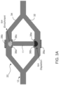
- FIG. 3A illustrates a static state in which no flow is forced into microchannel 12.
- a depletion and enrichment ionic concentration layers are formed at the anodic and cathodic sides of the membrane 11, respectively.
- FIG. 3B illustrates a state in which flow is forced into microchannel 12.
- the pattern of depletion and enrichment ionic concentration layers is changed due to the flow in branches 32 and 34, respectively.
- This change is sensed, for example, as the difference between the ion concentration (or proxy thereof) measured by sensing element 38a and the ion concentration (or proxy thereof) measured by sensing element 38b, both within the depletion ionic concentration deformed layer.
- This difference is correlated to the magnitude of the flow within microchannel 12. In the no-flow case
- this difference vanishes.
- This change can additionally or alternatively be sensed as the difference between the ion concentration (or proxy thereof) measured by sensing element 38c and the ion concentration (or proxy thereof) measured by sensing element 38d, both within the enrichment ionic concentration deformed layer.
- This change can additionally or alternatively be sensed also using a single sensing element, which can be the sensing element proximal to the as further detailed hereinabove.
- FIG. 3C illustrates a configuration in which additional sensing elements 38e, 38f are positioned downstream the flow relative to membrane 11.
- These sensing elements can be used to measure the elapsed time for the depletion ionic concentration layer to propagate from element 38a to element 38e (interchangeably referred to as the time-of-flight of the depletion ionic concentration layer) and/or the enrichment ionic concentration layer to propagate from element 38c to element 38f (interchangeably referred to as the time-of-flight of the enrichment ionic concentration layer).
- microchannel 12 is a non-branched fluidic microchannel
- medium 11 is embodied as a cation permselective membrane (e.g., Nafion) and is positioned to connect between two separate microchannels 33 and 35 at the opposite sides of the main microchannel 12.
- the two side microchannels 33 and 35 do not necessarily contain the same fluid as in microchannel 12. In some embodiments of the present invention they contain a stagnant electrolyte that allows the introduction of electrodes 28b for application of an electric field through the permselective medium.
- electric field optionally and preferably a symmetric electric field, with the line of symmetry along microchannel 12, is applied resulting in symmetric enrichment concentration layers within microchannels 33 and 35 and a symmetric depletion concentration layer within the main microchannel 12.
- electrodes 28b are cathodes preferably having the same negative potential
- electrodes 28a are anodes preferably having the same positive potential.
- the setup is not limited to the application of such a symmetric electric field and the electrodes 28b within the top side microchannel 35 can have a different potential from the electrodes 28b at the bottom side microchannel 33.
- the former have a higher potential than that of the latter, and electrodes 28a are merely floating, then both enrichment and depletion ionic concentration layers develop within the microchannel 12.
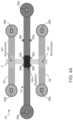
- FIG. 4A illustrates a static state in which no flow is forced into microchannel 12.
- depletion and enrichment ionic concentration layers are formed at the anodic and cathodic sides of the membrane 11, respectively.
- FIG. 4B illustrates a state in which flow is forced into microchannel 12.
- the pattern of depletion ionic concentration layer is changed due to the flow in the main microchannel 12 while the pattern of the enrichment ionic concentration layers is barely changed as the side microchannels do not sustain net flow.
- This change can be sensed by one of the sensing elements (e.g ., sensing element 38a ), for example, by extracting from the signal one or more electrical parameters or the time for saturation, and executing a correlation procedure to the flow parameter as further detailed hereinabove.
- This change can alternatively or additionally be sensed as the difference between the ion concentration (or proxy thereof) measured by sensing element 38a and the ion concentration (or proxy thereof) measured by sensing element 38b.
- This difference is correlated to the intensity of the flow within microchannel 12 .
- this difference vanishes.
- This change can additionally or alternatively be sensed as the difference between the ion concentration (or proxy thereof) measured by sensing element 38c and the ion concentration (or proxy thereof) measured by sensing element 38d.
- FIG. 4C illustrates an embodiment in which additional sensing elements 38e, 38f are positioned downstream the flow relative to membrane 11. These sensing elements can be used to measure the time-of-flight of the depletion ionic concentration layer from element 38a to element 38e, and/or from element 38c to element 38f.
- medium 11 is made, at least in part, of a permselective material.
- permselective material is advantageous because it enhances the CP effect at sides 24 and 26 of medium 11.
- permselective material refers to an ion permeable material having the property that the ion transport number (also called the transference number, and is the fraction of the total current carried by a given ion) through the material is higher for ionic species having a certain charge sign than for ionic species having the opposite charge sign.
- permselective material has the property that the transport number through the material is higher for ion of one species than for ions of another species.
- cations pass through the material more easily (i.e., while experiencing less resistive force) than anions.
- anions pass through the material more easily (i.e., while experiencing less resistive force) than cations.
- a permselective material is different from a porous structure that does not discriminate among differently charged ionic species as the species pass through the porous structure.
- the permselective material comprises a cation exchange material which is non-permeable to anions, and in some embodiments of the present invention the permselective material comprises an anion exchange material, which is non-permeable to cations.
- permselective materials may be employed for medium 11.
- Representative examples including, without limitation, the sulfonic acid substituted perfluorocarbon polymers of the type described in U.S. Patent No. 4,036,714 ; the primary amine substituted polymers described in U.S. Pat. No. 4,085,071 ; the polyamine substituted polymers of the type described in U.S. Pat. No. 4,030,988 ; and the carboxylic acid substituted polymers described in U.S. Pat. No. 4,065,366 .
- sulfonic acid substituted type materials include perfluorosulfonate cation exchange materials such as those membranes marketed commercially under the trademark NAFION ® , manufactured and sold by the E.I. duPont de Nemours, Wilmington, DE.
- Typical membranes include the NAFION ® 200 series, NAFION ® 204, 214, 255, 295, the NAFION ® 300 series, NAFION ® 313, 315, 316, 324, 336, 337, 355, 376, 390, 391, and the NAFION ® 400 series including NAFION ® 427 membrane, mixtures thereof and the like.
- an amniotic membrane extract (AMX) as a permselective medium.
- Medium 11 can be a nanochannel with at least one of its dimensions of the same order of magnitude as size of the electric double layer (EDL) so as to induce the overlap of EDLs from opposite channel walls.
- Techniques suitable for making such nanochannels include, without limitation, photolithography, nanofabrication techniques such as focused-ion-beam (FIB), E-beam, nano-imprint lithography and the like.
- ion permselective materials can be made of electrodes that support reaction with only one ionic species, such that effectively, it can be considered as permselective only for this ionic species that pass current through the reactions and leads to CP.
- permselective medium 11 When permselective medium 11 is embodied as an electrode in direct contact with the fluid, it can comprise an adhesion layer (e.g. chromium, titanium, tantalum) and a conductive layer deposited thereon (e.g. gold, platinum).
- adhesion layer e.g. chromium, titanium, tantalum
- a conductive layer deposited thereon e.g. gold, platinum
- microchannel 12 can be formed from solid materials, in which the microchannels can be formed via molding, micromachining, film deposition processes such as spin coating and chemical vapor deposition, laser fabrication, photolithographic techniques, etching methods including wet chemical or plasma processes, and the like.
- film deposition processes such as spin coating and chemical vapor deposition
- laser fabrication such as photolithographic techniques
- etching methods including wet chemical or plasma processes, and the like.
- three-dimensional freeform fabrication techniques such as three-dimensional jet printing, wherein patterns of printed material allow directional fluid transport.
- microchannel 12 can be formed of a polymer, for example, an elastomeric polymer such as polydimethylsiloxane (PDMS), polytetrafluoroethylene (PTFE) or the like. Technologies for precise and efficient formation of microfluidic systems from such materials are known.
- a polymer for example, an elastomeric polymer such as polydimethylsiloxane (PDMS), polytetrafluoroethylene (PTFE) or the like. Technologies for precise and efficient formation of microfluidic systems from such materials are known.
- PDMS polydimethylsiloxane
- PTFE polytetrafluoroethylene
- Microchannel 12 can be conveniently formed of a hardenable fluid, facilitating formation via molding (e.g ., replica molding, injection molding, cast molding, etc .).
- the hardenable liquid can be essentially any liquid that can be induced to solidify, or that spontaneously solidifies, into a solid capable of containing and/or transporting fluids contemplated for use in and with a microfluidic system.
- the hardenable liquid comprises a polymeric liquid or a liquid polymeric precursor. Suitable polymeric liquids can include, for example, thermoplastic polymers, thermoset polymers, or mixture of such polymers heated above their melting point.
- a suitable polymeric liquid may include a solution of one or more polymers in a suitable solvent, which solution forms a solid polymeric material upon removal of the solvent, for example, by evaporation.
- a suitable solvent such as a solvent for removing polymeric materials from, for example, a melt state or by solvent evaporation.
- Such polymeric materials which can be solidified from, for example, a melt state or by solvent evaporation, are well known to those of ordinary skill in the art.
- a variety of polymeric materials, many of which are elastomeric, are suitable.
- a non-limiting list of examples of such polymers includes polymers of the general classes of silicone polymers, epoxy polymers, and acrylate polymers. Epoxy polymers are characterized by the presence of a threemembered cyclic ether group commonly referred to as an epoxy group, 1,2-epoxide, or oxirane.
- diglycidyl ethers of bisphenol A can be used, in addition to compounds based on aromatic amine, triazine, and cycloaliphatic backbones.
- Another example includes the well-known Novolac polymers.
- Non-limiting examples of silicone elastomers suitable for use according to the invention include those formed from precursors including the chlorosilanes such as methylchlorosilanes, ethylchlorosilanes, phenylchlorosilanes, etc.
- silicone polymers are used.
- a representative example includes the silicone elastomer PDMS, which is commercially available, e.g., from Dow Chemical Co., Midland, Mich.
- Silicone polymers including PDMS have several beneficial properties simplifying formation of microchannel 12. For instance, such materials are inexpensive, readily available, and can be solidified from a liquid polymeric precursor via curing with heat. PDMSs are typically curable by exposure of the liquid polymeric precursor to temperatures of about 70 °C for exposure times of about an hour.
- Elastomeric polymer materials are also advantageous for their inertness to critical components of an analysis or synthesis to be carried out. Elastomeric polymer materials can also be coated with suitable materials as known in the art.
- Suitable materials are generally selected based upon their compatibility with the manufacturing process (injection molding, dry etching, embossing, bonding, soft lithography, stereolithography and three-dimensional jet printing, etc.) and the conditions present in the particular operation to be performed by the microfluidic system. Such conditions can include extremes of pH, pressure within the microchannels, temperature, ionic concentration, and the like.
- Electrodes 28 can be made of any electrically conductive material, such as, but not limited to, a metal (e.g ., gold, platinum, silver or silver chloride).
- electrodes 28 can be made of a semiconductor material, such as, but not limited to, a p-doped or n-doped semiconductor material (e.g ., silicon electrode doped with boron or silicon electrode is doped with phosphorous).
- a p-doped or n-doped semiconductor material e.g ., silicon electrode doped with boron or silicon electrode is doped with phosphorous.
- these electrodes can be made of any of the aforementioned electrically conductive or semiconductor materials.
- the microfluidic system of the invention can be used in many applications, preferably applications that require relatively low flow rate as indicated above.
- suitable applications include without limitation, genetic applications, chemical applications, biochemical applications, pharmaceutical applications, biomedical applications, chromatography applications, integrated circuit cooling, ink-jet printing, medical applications, radiological applications and environmental applications.
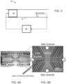
- microfluidic system 20 comprises a pump 42 for generating flow in microchannel 12, and a controller 44 configured for controlling pump 42 responsively to the flow parameter determined by sensor system 22, thereby forming a closed loop control between pump 42 and sensor system 22.
- a representative utilization of this application is the medical field, for example, for the administration of a compound to a subject.
- the system can be used as an insulin pump for providing a controlled rate of insulin delivery to a diabetic subject who would normally need multiple daily injections to regulate the blood glucose level.
- Existing pumps may not be as accurate as required by a particular treatment protocol, and the closed loop control of the present embodiments improves the accuracy of the delivery rate.
- the system of the present embodiments is useful also for other medical applications, particularly but not necessarily for diagnostic and patient management.
- the microfluidic system of the present embodiments is suitable for detecting hazardous materials or conditions such as air or water pollutants, chemical agents, biological organisms or radiological conditions.
- the microfluidic system of the present embodiments is suitable for testing and/or analysis of DNA, and other macro or smaller molecules, or reactions between such molecules in an approach known as "lab-on-chip.”
- the microfluidic system of the present embodiments can be used to obtain a variety of measurements including, without limitation, molecular diffusion coefficients, fluid viscosity, pH, chemical binding coefficients and enzyme reaction kinetics.
- Other uses for the microfluidic system of the present embodiments include, without limitation, immunoassays, flow cytometry, sample injection of proteins for analysis via mass spectrometry, sample injection of air or water samples for analysis via flamespectrometry, polymerase chain reaction (PCR) amplification, cell manipulation, cell separation, cell patterning and chemical gradient formation. Many of these applications have utility for basic research and clinical diagnostics.
- the microfluidic system of the present embodiments can be integrated in microchips, such as DNA chips, protein chips and total analysis systems.
- the microfluidic system of the present embodiments can be integrated in a DNA chip which includes a substrate for which probes with known identity are used to determine complementary binding, thus allowing massive parallel gene expression and gene discovery studies.
- the use of the microfluidic system of the present embodiments with such microchip can facilitate the production of small and highdensity spots on the substrate. Since only a small amount of solution is needed to make one chip, the cost of chip production is substantially reduced.
- the microfluidic system of the present embodiments can create spots in consistent quantities and with uniform shape and size, so as to allow highly accurate comparisons between spots.
- microfluidic system of the present embodiments can also be used as a chromatograph for performing liquid chromatography.
- microfluidic system of the present embodiments can also be used as a microfluidic printing device, in which inks are formed by moving precursors through microchannels.
- microfluidic system of the present embodiments can also be used as a microfluidic mixer, in which one or more fluids are moved through a mixer inserted in a microchannel.
- microfluidic system of the present embodiments can also be used as an optical device, in which a bubble or slug of fluid immiscible in a second fluid is moved through the second fluid to a spot of optical activity on the substrate.
- compositions, method or structure may include additional ingredients, steps and/or parts, but only if the additional ingredients, steps and/or parts do not materially alter the basic and novel characteristics of the claimed composition, method or structure.
- a compound or “at least one compound” may include a plurality of compounds, including mixtures thereof.
- range format is merely for convenience and brevity and should not be construed as an inflexible limitation on the scope of the invention. Accordingly, the description of a range should be considered to have specifically disclosed all the possible subranges as well as individual numerical values within that range. For example, description of a range such as from 1 to 6 should be considered to have specifically disclosed subranges such as from 1 to 3, from 1 to 4, from 1 to 5, from 2 to 4, from 2 to 6, from 3 to 6 etc., as well as individual numbers within that range, for example, 1, 2, 3, 4, 5, and 6. This applies regardless of the breadth of the range.
- FIGs. 6A and 6B show images of a prototype sensor system used in experiments performed according to some embodiments of the present invention, where FIG. 6B is a magnified view of a dotted portion shown in FIG. 6A .
- the prototype system included two side channels, a main channel, and a NAFION ® membrane connecting each of the side channels to the main channel.
- a positive electrical potential was applied at the ends of the main channel and a negative electrical potential was applied at the ends of the NAFION ® membrane.
- a series of pairs of sensing electrodes was deployed across the main channel, at both sides of the membrane.
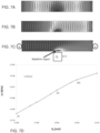
- FIGs. 7A-D show computer simulation results of ion concentration during the flow in the main channel, which are useful to understand the invention.
- FIGs. 7A-C show ion concentration patterns across the main channel at three different flow speeds (about 10 -5 m/s, about 10 -3 m/s, about 10- 2 m/s, respectively), and
- FIG. 7D is a graph of the conductivity change ⁇ in S/m as a function of the flow speed U o in m/s.
- the points on the graph marked by (i), (ii) and (iii) correspond, respectively, to FIGs. 7A-C .
- the simulations demonstrate that the shape and size of the ion concentration pattern is indicative of the flow speed.
- FIG. 8B shows graphs of the normalized impedance and normalized intensity of the signal, as a function of the time, as measured by a pair of sensing electrodes positioned about 500 ⁇ m downstream the membrane. The location of the sensing pair is marked by a block arrow in FIG. 8A . As shown, the impedance and intensity reached saturation after about 45 second.
- FIGs. 9A and 9B are graphs showing correlations between the flow speed of 1 mM KCl (in ⁇ m/s) and two measured parameters: the time to saturation of the impedance, in seconds ( FIG. 9A ), and the change in electrical impudence during saturation, in M ⁇ ( FIG. 9B ). As shown, the flow speed correlates well with both the parameters. The measurements were taken by a pair of sensing electrodes positioned about 130 ⁇ m downstream the membrane.
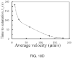
- FIGs. 10A-D are graphs showing results of measurements were taken across the membrane using the same pair of electrodes used for generating the electrical field across the membrane, during flow of 1 mM KCl.
- FIG. 10A is a graph showing the normalized electrical current as a function of the time in seconds during flow at an average speed of about 62.55 ⁇ m/s.
- FIG. 10B shows the normalized electrical current as a function of the time in seconds for several different flow speeds
- FIGs. 10C and 10D show correlations between the average flow speed in ⁇ m/s and two measured parameters: the electrical current during saturation ( FIG. 10C ), and the time to saturation of the electrical current, in seconds ( FIG. 10D ).
- the flow speed correlates well with both the parameters.
- FIGs. 11A-C are graphs showing results of measurements were taken across the membrane using the same pair of electrodes used for generating the electrical field across the membrane, during flow of insulin.
- FIG. 11A shows the normalized electrical current as a function of the time in seconds for several different flow speeds
- FIGs. 11B and 11C show correlations between the average flow speed in ⁇ m/s and two measured parameters: the electrical current during saturation ( FIG. 11B ), and the time to saturation of the electrical current, in seconds ( FIG. 11C ).
- the flow speed correlates well with both the parameters.
- the flow speed correlates with both the parameters.
Landscapes
- Chemical & Material Sciences (AREA)
- Health & Medical Sciences (AREA)
- Physics & Mathematics (AREA)
- Fluid Mechanics (AREA)
- General Physics & Mathematics (AREA)
- Dispersion Chemistry (AREA)
- Analytical Chemistry (AREA)
- General Health & Medical Sciences (AREA)
- Hematology (AREA)
- Clinical Laboratory Science (AREA)
- Chemical Kinetics & Catalysis (AREA)
- Automatic Analysis And Handling Materials Therefor (AREA)
Description
- The present invention relates to fluidic systems and, more particularly, but not exclusively, to a system and method for measuring flow.
- Much industrial and academic effort is presently directed at the development of integrated micro devices or systems combining electrical, mechanical and/or optical/electrooptical components, commonly known as Micro Electro Mechanical Systems (MEMS). MEMS are fabricated using integrated circuit batch processing techniques and can range in size from micrometers to millimeters. These systems can sense, control and actuate on the micro scale, and function individually or in arrays to generate effects on the macro scale. MEMS include numerous applications, such as airbag accelerometers, ink-jet heads, radio frequency micro-switches for wireless communications, micro-gyroscopes, digital micro-mirror displays, pico-satellites and the like.
- Whenever mechanics can replace electronics, it provides superior functionality and is not subject to undesirable electronic noise. For example, the classical electronic components of fiber-optic networks are now being replaced with optical MEMS switches that enable the creation of arrays of miniature high capacity switches which can play a critical role in the development of large-scale optical switches in fiber-optic networks.
- MEMS may consist of mechanical microstructures, microsensors, microactuators and electronics integrated in the same environment (e.g., on a silicon chip). The microfabrication technology enables fabrication of large arrays of devices, which individually perform simple tasks but in combination can accomplish complicated functions. For example, MEMS for guidance, navigation, motion control and high resolution flow visualization can provide experimental evidence about smallscale phenomena and thus verify fundamental principles in the microcosm.
- One type of MEMS is a microfluidic device. Microfluidic devices include components such as channels, reservoirs, mixers, pumps, valves, chambers, cavities, reaction chambers, heaters, fluidic interconnects, diffusers, nozzles, and other microfluidic components. These microfluidic components typically have dimensions between a few micrometers and a few hundreds of micrometers. The small dimensions of the components minimize the physical size, the power consumption, the response time and the waste of the entire system. Such systems may provide wearable miniature devices located either outside or inside the human body.
- Applications for microfluidic devices include genetic, chemical, biochemical, pharmaceutical, biomedical, chromatography, integrated circuit cooling, ink-jet printing, medical, radiological and environmental applications. The medical applications include diagnostic and patient management such as implanted drug dispensing systems. The environmental applications include detecting hazardous materials or conditions such as air or water pollutants, chemical agents, biological organisms or radiological conditions. The genetic and biochemical applications include testing and/or analysis of DNA, and other macro or smaller molecules, or reactions between such molecules in microfluidic devices, in an approach known as "lab-on-chip."
- Microfluidic devices presently occupy an increasingly significant position in chemical and biochemical sensing, molecular separations, drug delivery and other forefront technologies. In a manner similar to that for microelectronics, microfluidic technologies enable the fabrication of highly integrated devices applicable to high throughput, low volume, automatable chemical and biochemical analyses and syntheses. Common fluids used in microfluidic devices include whole blood samples, bacterial cell suspensions, protein or antibody or nucleic acid solutions and various buffers.
- Known in the art are thermal flow sensors that include a heating element immersed within fluidic channel. Upon application of forced fluid flow in the channel, temperature changes relative to the base state of the heating element are measured. The flow alters the temperature distribution through heat convection, and the measurement allows determining the flow rate in the channel.
-
United States Patent 7,225,683 discloses a device for measuring the flow rate of a fluid in a flow channel. The device includes means for creating localized compositional variations in the fluid along the flow axis, means for subsequently detecting the compositional variation at a point downstream from its point of creation, and means for measuring flight time. The device is capable of measuring flow rates from less than about 1 nL/min to greater than about 10 µL/min at pressures as great as 1.379×10⁷ pa (2,000 psi). - The present invention provides a microfluidic system according to
claim 1, and a method of sensing flow of fluid in a microchannel according to claim 13. - Unless otherwise defined, all technical and/or scientific terms used herein have the same meaning as commonly understood by one of ordinary skill in the art to which the invention pertains. Exemplary methods and/or materials which can be used in the practice or testing of invention are described below. In case of conflict, the patent specification, including definitions, will control. In addition, the materials, methods, and examples are illustrative only and are not intended to be necessarily limiting.
- Implementation of the method and/or system of embodiments of the invention can involve performing or completing selected tasks manually, automatically, or a combination thereof. Moreover, according to actual instrumentation and equipment of embodiments of the method and/or system of the invention, several selected tasks could be implemented by hardware, by software or by firmware or by a combination thereof using an operating system.
- For example, hardware for performing selected tasks according to embodiments of the invention could be implemented as a chip or a circuit. As software, selected tasks according to embodiments of the invention could be implemented as a plurality of software instructions being executed by a computer using any suitable operating system. In an exemplary embodiment of the invention, one or more tasks according to exemplary embodiments of method and/or system as described herein are performed by a data processor, such as a computing platform for executing a plurality of instructions. Optionally, the data processor includes a volatile memory for storing instructions and/or data and/or a non-volatile storage, for example, a magnetic hard-disk and/or removable media, for storing instructions and/or data. Optionally, a network connection is provided as well. A display and/or a user input device such as a keyboard or mouse are optionally provided as well.
- Some embodiments of the invention are herein described, by way of example only, with reference to the accompanying drawings. With specific reference now to the drawings in detail, it is stressed that the particulars shown are by way of example and for purposes of illustrative discussion of embodiments of the invention. In this regard, the description taken with the drawings makes apparent to those skilled in the art how embodiments of the invention may be practiced.
- In the drawings:
-
FIGs. 1A and 1B show representative example of a concentration polarization (CP) effect demonstrated according to some embodiments of the present invention; -
FIG. 2 is a schematic illustration of a microfluidic system, according to some embodiments of the present invention; -
FIGs. 3A-C are useful to understand the invention and schematically illustrate a representative mode of operation of a microfluidic system in which a separate pair of electrodes is used for sensing; -
FIGs. 4A-C schematically illustrate an additional representative mode of operation of a microfluidic system according to some embodiments of the present invention; and -
FIG. 5 is a schematic illustration of a microfluidic system, in embodiments of the invention in which the system includes a pump and a controller. -
FIGs. 6A and 6B show images of a prototype sensor system used in experiments performed to demonstrate the present invention; -
FIGs. 7A-D show computer simulation results useful to understand the present invention; -
FIG. 8A is a series of images showing snapshots of a main channel of the prototype sensor system at different times during flow of 1 mM KCl at average speed of 66.4 µm/s, as measured in experiments performed to demonstrate the present invention; -
FIG. 8B includes graphs that are useful to understand the invention and which show normalized impedance and normalized intensity of a signal, as a function of the time, as measured in experiments performed to demonstrate the present invention; -
FIGs. 9A and9B are graphs that are useful to understand the invention and which show correlations between the flow speed of 1 mM KCl (in µm/s) and two measured parameters: the time to saturation of the impedance (FIG. 9A ), and the change in electrical impedance during saturation (FIG. 9B ); -
FIGs. 10A-D are graphs that are useful to understand the invention and which show results of measurements taken across a membrane of the prototype sensor system, during flow of 1 mM KCl, as obtained in experiments performed to demonstrate the present invention; and -
FIGs. 11A-C are graphs that are useful to understand the invention and which show results of measurements taken across a membrane of the prototype sensor system, during flow of insulin, as obtained in experiments performed to demonstrate the present invention. - The present invention relates to fluidic systems and, more particularly, but not exclusively, to a system and method for measuring flow.
- Before explaining at least one embodiment of the invention in detail, it is to be understood that the invention is not necessarily limited in its application to the details of construction and the arrangement of the components and/or methods set forth in the following description and/or illustrated in the drawings and/or the Examples. The invention is capable of other embodiments or of being practiced or carried out in various ways.
- The present invention induces a concentration polarization (CP) effect for measuring a flow parameter. In this effect local ionic concentration gradients are generated at an interface of fluid and an ion permselective medium upon application of voltage or current across the permselective medium. More specifically an enriched ionic concentration is formed at one side of the permselective medium and a depleted ionic concentration is formed at its opposite side, when both sides interface a fluid. When a pair of electrodes is in contact with the fluid (e.g., submerged) a change of the ion concentration can be electrochemically generated, for example, by a process of electrolysis of a solvent or species dissolved therein. Specifically, local composition variations can be formed by electrochemical oxidation or reduction of a redox couple at each electrode of the pair, thereby producing a region of increased or decreased conductivity that can be used to determine fluid flow rate.
- A representative example of the CP effect is shown in
FIGs. 1A and 1B. FIG. 1A is an image of ananochannel 10 having negative surface charges and being flanked by twomicrochannels 12 arranged co-linearly. The microchannels are filled with a solution containing a KCl electrolyte and Rhodamine 6G fluorescent dye. An electric field is applied across the nanochannel. The direction of the electric field is shown byarrow 14. A microscopic image ofnanochannel 10 andmicrochannels 12 is shown inFIG. 1B . As shown inFIG. 1A , ionic concentration polarization is generated at both sides ofnanochannel 10 wherein a depletion of ions is formed at a region marked byarrow 18 and an enrichment of ions is marked byarrow 16. -
FIG. 2 is a schematic illustration of amicrofluidic system 20, according to some embodiments of the present invention. - The term "microfluidic system" as used herein refers to a system having one or more fluid microchannels.
- The term "microchannel" as used herein refers to a fluid channel having crosssectional dimensions the smallest of which being less than 1 mm, more preferably less than 500 µm, more preferably less than 400 µm, more preferably less than 300 µm, more preferably less than 200 µm, e.g., about 100 µm or about 10µm.
- Thus,
system 20 comprises one or more fluidic microchannels, such as, but not limited to,microchannels 12.Microchannel 12 can be a linear microchannel, in which case microchannels 12 extends along a generally (e.g., within deviation of 10% or less) straight line, or a nonlinear microchannel, in which case at least part ofmicrochannels 12 extends along a curved line.Microchannel 12 can also be formed of a plurality of interconnected segments. These embodiments include a configuration in which all the segments are linear, or configuration in which all the segments are nonlinear, or a configuration in at least one of the segments is linear and at least one of the segments is nonlinear. - The length of
microchannel 12 can vary, depending on the application for whichsystem 20 is employed. As a representative non-limiting example, the overall length ofmicrochannel 20 is from about 0.1 cm to about 20 cm. -
System 20 also comprises a sensor system generally shown at 22. -
Sensor system 22 detects at least one flow parameter characterizing the flow inmicrochannel 12 by exploiting the aforementioned CP effect.Sensor system 22 comprises one or moreion permselective medium 11 having afirst side 24 and asecond side 26. - Ion permselective medium 11 can be any medium made, at least in part from a permselective material, and can have any structure, including, without limitation, a nanostructure, a nanoporous membrane and an electrode. The permselective medium 11 can, in some embodiments, be embodied as a permselective nanochannel, such as, but not limited to,
nanochannel 10. - Ion permselective medium 11 is positioned in
microchannel 12 to allow contact ofsides microchannel 12. This creates an interface between the fluid inmicrochannel 12 andmedium 11, thereby allowingsensor system 22 to utilize the CP effect. -
System 20 further comprises an arrangement ofelectrodes 28 arranged to generate an electric field acrosspermselective medium 11. This can be done by connectingelectrodes 28 to apower source 36, which may effect an electrical potential difference acrosspermselective medium 11. Via the CP effect, ionic concentration gradients are formed inmicrochannel 12, near sides 24 and 26 ofpermselective medium 11.FIG. 2 illustrates twoelectrodes microchannel 12. These electrodes do not necessarily be positioned in the vicinity of the permselective medium 11, but can also be applied further away (e.g., via electrodes immersed within the reservoirs of the inlets/outlets of the microchannels). However, this need not necessarily be the case, since, for some applications, it may be desired to positionelectrodes 28 insidemicrochannel 12. - In various exemplary embodiments of the
invention system 20 comprises an ionconcentration sensing system 38 configured to provide sensing signals indicative of ion concentration patterns (for example, shape, size) effected by the flow of fluid in the microchannel. These patterns typically constitute ionic concentration gradients. Optionally and preferably,system controller 37 that controlspower source 36 to ensure that the duration of the electric field generated byelectrodes 28 is longer than, e.g., at least twice, the time required for the sensing signals provided bysystem 38 to exhibit saturation. - The time required for the sensing signals to exhibit saturation is referred to herein as "time-to-saturate" and denoted τ. The time-to-saturate τ can be defined as a difference t1-t0 between two instants of time t1 and t0, where t0 is an onset time of the electric filed, and t1 is an instant of time at which the time-derivative of the signal, in absolute value, reaches about 20% or 10% or 5% of its value at time t0.
- As used herein, "saturation" of a signal means a situation in which the magnitude of the signal does not vary by more than X% over a period of time that is at least the time-to-saturate τ, where X is about 20 or about 10 or about 5.
- Typically, but not necessarily, a situation in which the magnitude of the signal does not vary by more than 20% or more than 10% or more than 5% or over a period of 1 second or 2 seconds.
- Ion
concentration sensing system 38 can be of any type that is sensitive to ionic concentration and that can generate signals indicative of ion concentration patterns. Representative examples of such systems include, without limitation a spectroscopic system (e.g., atomic absorption spectroscopy, UV-visible spectroscopy etc.), an optical sensing system, an electric sensing system and a magnetic sensing system. - In some embodiments of the present invention ion
concentration sensing system 38 has asensing element 38a, which can be embodied, for example, as a pair of electrodes, which provides sensing signals indicative of a local ion concentration pattern. In some embodiments of the presentinvention sensing element 38a is proximal to permselective medium 11, but embodiments in which the sensing element is placed downstream or upstream medium 11 are also contemplated. In some embodiments of thepresent invention system 22 detects the flow parameter(s) by analyzing a sensing signal received from a single sensing element (e.g., sensingelement 38a) of ionconcentration sensing system 38. - According to the invention, the electric field and the sensing signals are generated by the same set of electrodes, e.g.,
electrodes 28.Electrodes 28 are optionally and preferably withinchannel 12.System 22 can be devoid of passive electrodes such aselectrodes 38. Thus, for example, the system can include a pair of electrodes positioned at opposite sides of the permselective medium, in contact with the fluid, wherein these electrodes are used both for generating an electric field and for sensing the ion concentration pattern across the permselective medium. - In some embodiments of the present invention,
sensing system 38 is embodied as an arrangement of electrode pairs (e.g., a first pair ofelectrodes 38a, and a second pair ofelectrodes 38b) that are employed as one or more sensing pairs wherein electrical current, electrical impedance, electrical resistance, electrical conductance or the like, that is sensed by these pairs of electrodes is indicative of conductivity patterns near or at these electrodes. Since conductivity correlates with ion concentration, each of thepairs concentration sensing system 38. - While some embodiments are described with a particular emphasis to an ion concentration sensing system which is an electric sensing system, it is to be understood that more detailed reference to an electric sensing system is not to be interpreted as limiting the scope of the invention in any way.
-
System 20 comprises asignal processor 30 configured for analyzing the signals provided bysystem 38 and for determining at least one flow parameter characterizing the flow inmicrochannel 12. For clarity of presentation,processor 30 is shown to be connected only toelectrode pair 38b, but in a preferred embodiment theprocessor 30 communicates with all the sensing elements ofsystem 38 and/orelectrodes 28. For example, whenelectrodes 28 are used both for generating an electric field and for sensing the ion concentration pattern across the permselective medium,processor 30 communicates withelectrodes 28, andsystem 20 can, but not necessarily, be devoid ofelectrodes 38. -
Processor 30 can include an analog circuit for performing the analysis or it can include an analog-to-digital circuit form converting the signal to digital signals and a digital processing circuit for performing at least a portion of the analysis in a digital manner. - The parameter determined by
processor 30 can be a numerical parameter such as, but not limited to, flow rate, a change in flow rate (e.g., the time-derivative of the flow rate and/or a gradient of flow rate), and a flow direction. The parameter is optionally and preferably extracted after a calibration process from raw local measurements of electrical parameter such as, but not limited to, an electrical current, an electrical impedance, an electrical resistance and/or an electrical conductance. The parameter determined byprocessor 30 can also be a local numerical parameter, such as, but not limited to, velocity vector field, change in the velocity field (e.g., the time-derivative of the velocity field and/or a gradient of velocity field) and the direction of the velocity field vector. The advantage of determining the direction of the flow is that it allowssensor system 22 to measure the flow parameter both when the fluid flow in one direction inmicrochannel 12, and when the fluid flow in the opposite direction inmicrochannel 12. - When the sensing elements of
system 38 comprise electrodes (e.g., electrode pairs 38a and 38b) the sensing elements can be positioned in proximity tosides medium 11. Alternatively or additionally, one or more of the sensing elements is positioned farther from the respective end. When the sensing elements are in proximity tosides medium 11,processor 30 optionally and preferably measures changes in the conductivity pattern atsides -
Processor 30 can determine the flow pattern in more than one way. In some embodiments of thepresent invention processor 30 extracts from the sensing signals generated by one or more the sensing elements an electrical parameter (e.g., an electrical current, an electrical impedance, an electrical resistance and/or an electrical conductance), and correlates the extracted electrical parameter(s) to the flow parameter, optionally and preferably by direct correlation. The electrical parameter can be extracted separately from signals provided by different sensing elements, so that signals received from a single sensing element can be used byprocessor 30 to determine the flow parameter. When several sensing elements are used,processor 30 can determine the flow parameter based on signals received from any of these sensing elements. Preferably,processor 30 monitors the signals received from one or more of the sensing elements and determines whether or not these signals exhibit saturation, wherein the electrical parameter(s) are extracted during the saturation phase of the signals. -
Processor 30 can also receive from controller 37 a clock signal indicative of the onset time of the electric field acrossmedium 11, and use this clock signal to determine the elapsed time from the onset of the electric field to the onset of saturation. In these embodiments,processor 30 can optionally and preferably correlate this elapsed time to the flow parameter. -
Processor 30 can also determine the flow parameter by means of a time-of-flight (TOF) measurements. These embodiments are useful when there is one or more sensing elements that is located proximal tomedium 11, and one or more additional sensing elements located farther frommedium 11, downstream with respect tomedium 11.Processor 30 can measure the time interval that passes when the concentration pattern moves from medium 11 to the sensing element (referred to herein as the TOF of the concentration pattern). The TOF can be defined as the elapsed time between receipts of signals from the sensing element proximal tomedium 11 and the sensing element farther and downstream frommedium 11. -
System 22 can employ two or more of the above techniques for determining the flow parameter, and output the result of each of these techniques, e.g., to adisplay device 31. Alternatively or additionally,processor 30 can output only a selected result, based on a predetermined criterion, such as, but not limited to, reproducibility and definiteness (non-ambiguity). - Thus,
sensor system 22 optionally and preferably mimics a MEMS based thermal flow-meter sensor since it allows measuring the flow (a) at the permselective medium; (b) in proximity to the permselective medium; and/or (c) farther from the permselective medium, downstream therefrom. - Configuring
processor 30 for determining any of the above parameters can be by calibration. For example, known flow rates can be transmitted throughmicrochannel 12 and the signals fromsystem 38 and/orelectrodes 28 can be recorded and their pattern can be stored in a recording medium. In operation,processor 30 can compare the received signals with the stored signals and determine the flow rate based on the comparison. Similarly, known changes in flow rates can be transmitted throughmicrochannel 12 and the signals fromelectrodes 28 can be recorded and their pattern can be stored in a recording medium. In operation,processor 30 can compare the received signals with the stored signals and determine the change of flow rate based on the comparison. Similarly, known flow directions can be transmitted throughmicrochannel 12 and the signals fromsystem 38 can be recorded and their pattern can be stored in a recording medium. In operation,processor 30 can compare the received signals with the stored signals and determine the direction of flow based on the comparison. - In any of the above calibration procedures, rather than storing the recorded patterns themselves, a calibration curve or lookup table can be stored on a computer readable medium. Such calibration curve or lookup table can include correlations found during the calibration process between the measured parameter (e.g., electrical parameter, time to reach saturation, time-of-flight) and the flow parameter, such that in operation,
processor 30 extracts the respective parameter from the signals and correlates it to the flow parameter using the calibration curve or lookup table. Representative examples of calibration curves suitable for the present embodiments are shown in the Examples section that follows (see, for example,FIGs. 7D ,9A ,9B ,10C ,10D ,11B and 11C ). - Typically, the recording and comparison and/or correlation are done digitally, in which
case processor 30 is a digital signal processor. However, recording and comparison of analog signals and the use of analog processor is also contemplated. -
System 20 can be used to convey, handle or analyze many types of fluids inmicrochannel 12. Representative examples including, without limitation, water, a biological fluid (for example, body fluid, e.g., blood, plasma, urine, saliva, vaginal secretions, feces, interstitial fluid, wound excrement), a bacterial cell suspension, a protein medium, an antibody medium, a nucleic acid medium, ink, and fluid media commonly used in standard medical applications such as phosphate buffered saline or other medicinal liquids (e.g., insulin, growth hormone, hemostatic agent solution). The fluid may include one or more types of objects therein, such as, but not limited to, a mixture of cell types. The fluid can also be of any type, including any chemical analytes, reagents, compounds etc. - Typically,
sensor system 22 ofsystem 20 is useful for measuring relative low flow rates (e.g., flow rate of less than 500 microliter per minute, or less than 100 microliter per minute, or less than 50 microliter per minute, or less than 25 microliter per minute, or less than 10 microliter per minute, or less than 5 microliter per minute, or less than 1 microliter per minute, or less than 0.1 microliter per minute, or less than 0.01 microliter per minute). - A representative mode of operation of the microfluidic system in which a separate pair of electrodes is used for sensing is illustrated in
FIGs. 3A-C . In this example,microchannel 12 is a branched fluidic microchannel, andmedium 11 is embodied as a cation permselective membrane (e.g., Nation) and is positioned to connect between twobranches microchannel 12.FIG. 3A illustrates a static state in which no flow is forced intomicrochannel 12. Upon application of a voltage drop betweenelectrodes membrane 11, respectively. -
FIG. 3B illustrates a state in which flow is forced intomicrochannel 12. The pattern of depletion and enrichment ionic concentration layers is changed due to the flow inbranches element 38a and the ion concentration (or proxy thereof) measured by sensingelement 38b, both within the depletion ionic concentration deformed layer. This difference is correlated to the magnitude of the flow withinmicrochannel 12. In the no-flow case - (
FIG. 3A ) this difference vanishes. This change can additionally or alternatively be sensed as the difference between the ion concentration (or proxy thereof) measured by sensingelement 38c and the ion concentration (or proxy thereof) measured by sensingelement 38d, both within the enrichment ionic concentration deformed layer. This change can additionally or alternatively be sensed also using a single sensing element, which can be the sensing element proximal to the as further detailed hereinabove. -
FIG. 3C illustrates a configuration in whichadditional sensing elements membrane 11. These sensing elements can be used to measure the elapsed time for the depletion ionic concentration layer to propagate fromelement 38a toelement 38e (interchangeably referred to as the time-of-flight of the depletion ionic concentration layer) and/or the enrichment ionic concentration layer to propagate fromelement 38c toelement 38f (interchangeably referred to as the time-of-flight of the enrichment ionic concentration layer). - Another example of a possible mode of operation of the microfluidic system of the present embodiments is illustrated in
FIGs. 4A-C . In this example,microchannel 12 is a non-branched fluidic microchannel, andmedium 11 is embodied as a cation permselective membrane (e.g., Nafion) and is positioned to connect between twoseparate microchannels main microchannel 12. The two side microchannels 33 and 35 do not necessarily contain the same fluid as inmicrochannel 12. In some embodiments of the present invention they contain a stagnant electrolyte that allows the introduction ofelectrodes 28b for application of an electric field through the permselective medium. - In the specific example shown in
FIGs.4A-C electric field, optionally and preferably a symmetric electric field, with the line of symmetry alongmicrochannel 12, is applied resulting in symmetric enrichment concentration layers withinmicrochannels main microchannel 12. In this example of a cation permselective membrane,electrodes 28b are cathodes preferably having the same negative potential, andelectrodes 28a are anodes preferably having the same positive potential. - However, the setup is not limited to the application of such a symmetric electric field and the
electrodes 28b within thetop side microchannel 35 can have a different potential from theelectrodes 28b at thebottom side microchannel 33. For example, when the former have a higher potential than that of the latter, andelectrodes 28a are merely floating, then both enrichment and depletion ionic concentration layers develop within themicrochannel 12. -
FIG. 4A illustrates a static state in which no flow is forced intomicrochannel 12. Upon application of a voltage drop betweenelectrodes membrane 11, respectively. -
FIG. 4B illustrates a state in which flow is forced intomicrochannel 12. The pattern of depletion ionic concentration layer is changed due to the flow in themain microchannel 12 while the pattern of the enrichment ionic concentration layers is barely changed as the side microchannels do not sustain net flow. This change can be sensed by one of the sensing elements (e.g., sensingelement 38a), for example, by extracting from the signal one or more electrical parameters or the time for saturation, and executing a correlation procedure to the flow parameter as further detailed hereinabove. This change can alternatively or additionally be sensed as the difference between the ion concentration (or proxy thereof) measured by sensingelement 38a and the ion concentration (or proxy thereof) measured by sensingelement 38b. This difference is correlated to the intensity of the flow withinmicrochannel 12. In the no-flow case (FIG. 4A ) this difference vanishes. This change can additionally or alternatively be sensed as the difference between the ion concentration (or proxy thereof) measured by sensingelement 38c and the ion concentration (or proxy thereof) measured by sensingelement 38d. -
FIG. 4C illustrates an embodiment in whichadditional sensing elements membrane 11. These sensing elements can be used to measure the time-of-flight of the depletion ionic concentration layer fromelement 38a toelement 38e, and/or fromelement 38c toelement 38f. - In various exemplary embodiments of
medium 11 is made, at least in part, of a permselective material. The use of permselective material is advantageous because it enhances the CP effect atsides medium 11. - The term "permselective material," as used herein, refers to an ion permeable material having the property that the ion transport number (also called the transference number, and is the fraction of the total current carried by a given ion) through the material is higher for ionic species having a certain charge sign than for ionic species having the opposite charge sign.
- In some embodiments of the present invention permselective material has the property that the transport number through the material is higher for ion of one species than for ions of another species.
- For example, in a permselective material such as a cation exchange membrane, cations pass through the material more easily (i.e., while experiencing less resistive force) than anions. In a permselective material such as an anion exchange membrane, anions pass through the material more easily (i.e., while experiencing less resistive force) than cations.
- A permselective material is different from a porous structure that does not discriminate among differently charged ionic species as the species pass through the porous structure.
- In some embodiments of the present invention the permselective material comprises a cation exchange material which is non-permeable to anions, and in some embodiments of the present invention the permselective material comprises an anion exchange material, which is non-permeable to cations.
- A variety of permselective materials may be employed for
medium 11. Representative examples including, without limitation, the sulfonic acid substituted perfluorocarbon polymers of the type described inU.S. Patent No. 4,036,714 ; the primary amine substituted polymers described inU.S. Pat. No. 4,085,071 ; the polyamine substituted polymers of the type described inU.S. Pat. No. 4,030,988 ; and the carboxylic acid substituted polymers described inU.S. Pat. No. 4,065,366 . - Examples of sulfonic acid substituted type materials include perfluorosulfonate cation exchange materials such as those membranes marketed commercially under the trademark NAFION®, manufactured and sold by the E.I. duPont de Nemours, Wilmington, DE. Typical membranes include the
NAFION ® 200 series, NAFION® 204, 214, 255, 295, theNAFION ® 300 series, NAFION® 313, 315, 316, 324, 336, 337, 355, 376, 390, 391, and the NAFION® 400 series including NAFION® 427 membrane, mixtures thereof and the like. Also contemplated is the use of an amniotic membrane extract (AMX) as a permselective medium. -
Medium 11 can be a nanochannel with at least one of its dimensions of the same order of magnitude as size of the electric double layer (EDL) so as to induce the overlap of EDLs from opposite channel walls. Techniques suitable for making such nanochannels, include, without limitation, photolithography, nanofabrication techniques such as focused-ion-beam (FIB), E-beam, nano-imprint lithography and the like. - Other ion permselective materials can be made of electrodes that support reaction with only one ionic species, such that effectively, it can be considered as permselective only for this ionic species that pass current through the reactions and leads to CP.
- When permselective medium 11 is embodied as an electrode in direct contact with the fluid, it can comprise an adhesion layer (e.g. chromium, titanium, tantalum) and a conductive layer deposited thereon (e.g. gold, platinum).
- A variety of materials and processes can be used to form
microchannel 12. In some cases, the various materials selected lend themselves to fabrication techniques. For example,microchannel 12 can be formed from solid materials, in which the microchannels can be formed via molding, micromachining, film deposition processes such as spin coating and chemical vapor deposition, laser fabrication, photolithographic techniques, etching methods including wet chemical or plasma processes, and the like. Also contemplated are three-dimensional freeform fabrication techniques, such as three-dimensional jet printing, wherein patterns of printed material allow directional fluid transport. - At least a portion of
microchannel 12 can be formed of a polymer, for example, an elastomeric polymer such as polydimethylsiloxane (PDMS), polytetrafluoroethylene (PTFE) or the like. Technologies for precise and efficient formation of microfluidic systems from such materials are known. -
Microchannel 12 can be conveniently formed of a hardenable fluid, facilitating formation via molding (e.g., replica molding, injection molding, cast molding, etc.). The hardenable liquid can be essentially any liquid that can be induced to solidify, or that spontaneously solidifies, into a solid capable of containing and/or transporting fluids contemplated for use in and with a microfluidic system. In one embodiment, the hardenable liquid comprises a polymeric liquid or a liquid polymeric precursor. Suitable polymeric liquids can include, for example, thermoplastic polymers, thermoset polymers, or mixture of such polymers heated above their melting point. As another example, a suitable polymeric liquid may include a solution of one or more polymers in a suitable solvent, which solution forms a solid polymeric material upon removal of the solvent, for example, by evaporation. Such polymeric materials, which can be solidified from, for example, a melt state or by solvent evaporation, are well known to those of ordinary skill in the art. A variety of polymeric materials, many of which are elastomeric, are suitable. A non-limiting list of examples of such polymers includes polymers of the general classes of silicone polymers, epoxy polymers, and acrylate polymers. Epoxy polymers are characterized by the presence of a threemembered cyclic ether group commonly referred to as an epoxy group, 1,2-epoxide, or oxirane. For example, diglycidyl ethers of bisphenol A can be used, in addition to compounds based on aromatic amine, triazine, and cycloaliphatic backbones. Another example includes the well-known Novolac polymers. Non-limiting examples of silicone elastomers suitable for use according to the invention include those formed from precursors including the chlorosilanes such as methylchlorosilanes, ethylchlorosilanes, phenylchlorosilanes, etc. - In some cases silicone polymers are used. A representative example includes the silicone elastomer PDMS, which is commercially available, e.g., from Dow Chemical Co., Midland, Mich. Silicone polymers including PDMS have several beneficial properties simplifying formation of
microchannel 12. For instance, such materials are inexpensive, readily available, and can be solidified from a liquid polymeric precursor via curing with heat. PDMSs are typically curable by exposure of the liquid polymeric precursor to temperatures of about 70 °C for exposure times of about an hour. Elastomeric polymer materials are also advantageous for their inertness to critical components of an analysis or synthesis to be carried out. Elastomeric polymer materials can also be coated with suitable materials as known in the art. - Other types of materials for
microchannel 12 are also contemplated. Suitable materials are generally selected based upon their compatibility with the manufacturing process (injection molding, dry etching, embossing, bonding, soft lithography, stereolithography and three-dimensional jet printing, etc.) and the conditions present in the particular operation to be performed by the microfluidic system. Such conditions can include extremes of pH, pressure within the microchannels, temperature, ionic concentration, and the like. -
Electrodes 28 can be made of any electrically conductive material, such as, but not limited to, a metal (e.g., gold, platinum, silver or silver chloride). Alternatively,electrodes 28 can be made of a semiconductor material, such as, but not limited to, a p-doped or n-doped semiconductor material (e.g., silicon electrode doped with boron or silicon electrode is doped with phosphorous). In embodiments in which the sensing elements ofsystem 38 include electrodes, these electrodes can be made of any of the aforementioned electrically conductive or semiconductor materials. - Generally, the microfluidic system of the invention can be used in many applications, preferably applications that require relatively low flow rate as indicated above. Representative example of suitable applications include without limitation, genetic applications, chemical applications, biochemical applications, pharmaceutical applications, biomedical applications, chromatography applications, integrated circuit cooling, ink-jet printing, medical applications, radiological applications and environmental applications.
- A representative application which can employ the microfluidic system of the present embodiments is illustrated in
FIG. 5 . In this representative application,microfluidic system 20 comprises apump 42 for generating flow inmicrochannel 12, and acontroller 44 configured for controllingpump 42 responsively to the flow parameter determined bysensor system 22, thereby forming a closed loop control betweenpump 42 andsensor system 22. A representative utilization of this application is the medical field, for example, for the administration of a compound to a subject. For example, the system can be used as an insulin pump for providing a controlled rate of insulin delivery to a diabetic subject who would normally need multiple daily injections to regulate the blood glucose level. Existing pumps may not be as accurate as required by a particular treatment protocol, and the closed loop control of the present embodiments improves the accuracy of the delivery rate. - The system of the present embodiments is useful also for other medical applications, particularly but not necessarily for diagnostic and patient management. For environmental applications the microfluidic system of the present embodiments is suitable for detecting hazardous materials or conditions such as air or water pollutants, chemical agents, biological organisms or radiological conditions. For genetic and biochemical applications the microfluidic system of the present embodiments is suitable for testing and/or analysis of DNA, and other macro or smaller molecules, or reactions between such molecules in an approach known as "lab-on-chip."
- The microfluidic system of the present embodiments can be used to obtain a variety of measurements including, without limitation, molecular diffusion coefficients, fluid viscosity, pH, chemical binding coefficients and enzyme reaction kinetics. Other uses for the microfluidic system of the present embodiments include, without limitation, immunoassays, flow cytometry, sample injection of proteins for analysis via mass spectrometry, sample injection of air or water samples for analysis via flamespectrometry, polymerase chain reaction (PCR) amplification, cell manipulation, cell separation, cell patterning and chemical gradient formation. Many of these applications have utility for basic research and clinical diagnostics.
- The microfluidic system of the present embodiments can be integrated in microchips, such as DNA chips, protein chips and total analysis systems. For example, the microfluidic system of the present embodiments can be integrated in a DNA chip which includes a substrate for which probes with known identity are used to determine complementary binding, thus allowing massive parallel gene expression and gene discovery studies. The use of the microfluidic system of the present embodiments with such microchip can facilitate the production of small and highdensity spots on the substrate. Since only a small amount of solution is needed to make one chip, the cost of chip production is substantially reduced. In addition, the microfluidic system of the present embodiments can create spots in consistent quantities and with uniform shape and size, so as to allow highly accurate comparisons between spots.
- The microfluidic system of the present embodiments can also be used as a chromatograph for performing liquid chromatography.
- The microfluidic system of the present embodiments can also be used as a microfluidic printing device, in which inks are formed by moving precursors through microchannels.
- The microfluidic system of the present embodiments can also be used as a microfluidic mixer, in which one or more fluids are moved through a mixer inserted in a microchannel.
- The microfluidic system of the present embodiments can also be used as an optical device, in which a bubble or slug of fluid immiscible in a second fluid is moved through the second fluid to a spot of optical activity on the substrate.
- The term "consisting essentially of' means that the composition, method or structure may include additional ingredients, steps and/or parts, but only if the additional ingredients, steps and/or parts do not materially alter the basic and novel characteristics of the claimed composition, method or structure.
- As used herein, the singular form "a", "an" and "the" include plural references unless the context clearly dictates otherwise. For example, the term "a compound" or "at least one compound" may include a plurality of compounds, including mixtures thereof.
- Throughout this application, various embodiments of this invention may be presented in a range format. It should be understood that the description in range format is merely for convenience and brevity and should not be construed as an inflexible limitation on the scope of the invention. Accordingly, the description of a range should be considered to have specifically disclosed all the possible subranges as well as individual numerical values within that range. For example, description of a range such as from 1 to 6 should be considered to have specifically disclosed subranges such as from 1 to 3, from 1 to 4, from 1 to 5, from 2 to 4, from 2 to 6, from 3 to 6 etc., as well as individual numbers within that range, for example, 1, 2, 3, 4, 5, and 6. This applies regardless of the breadth of the range.
- Whenever a numerical range is indicated herein, it is meant to include any cited numeral (fractional or integral) within the indicated range. The phrases "ranging/ranges between" a first indicate number and a second indicate number and "ranging/ranges from" a first indicate number "to" a second indicate number are used herein interchangeably and are meant to include the first and second indicated numbers and all the fractional and integral numerals therebetween.
- It is appreciated that certain features of the invention, which are, for clarity, described in the context of separate embodiments, may also be provided in combination in a single embodiment.
- Certain features described in the context of various embodiments are not to be considered essential features of those embodiments, unless the embodiment is inoperative without those elements.
- Various embodiments and aspects of the present invention as delineated hereinabove and as claimed in the claims section below find experimental support in the following examples.
- Reference is now made to the following examples, which together with the above descriptions illustrate some embodiments of the invention in a non-limiting fashion.
-
FIGs. 6A and 6B show images of a prototype sensor system used in experiments performed according to some embodiments of the present invention, whereFIG. 6B is a magnified view of a dotted portion shown inFIG. 6A . The prototype system included two side channels, a main channel, and a NAFION® membrane connecting each of the side channels to the main channel. In the experiments, a positive electrical potential was applied at the ends of the main channel and a negative electrical potential was applied at the ends of the NAFION® membrane. A series of pairs of sensing electrodes was deployed across the main channel, at both sides of the membrane. - Two types of fluids were used in the experiments: a 1 mM KCl (conductivity of 100µS/cm) and Insulin (conductivity of 2.1 mS/cm).
- F
IGs. 7A-D show computer simulation results of ion concentration during the flow in the main channel, which are useful to understand the invention.FIGs. 7A-C show ion concentration patterns across the main channel at three different flow speeds (about 10-5 m/s, about 10-3 m/s, about 10-2 m/s, respectively), andFIG. 7D is a graph of the conductivity change Δσ in S/m as a function of the flow speed Uo in m/s. The points on the graph marked by (i), (ii) and (iii) correspond, respectively, toFIGs. 7A-C . The simulations demonstrate that the shape and size of the ion concentration pattern is indicative of the flow speed. -
FIG. 8A is a series of images showing snapshots of the main channel at different times (t = 0, 5, 10, 20, 40, 60, 80, 100 and 200 seconds) during flow of 1 mM KC1 at average speed of 66.4 µm/s.FIG. 8B shows graphs of the normalized impedance and normalized intensity of the signal, as a function of the time, as measured by a pair of sensing electrodes positioned about 500 µm downstream the membrane. The location of the sensing pair is marked by a block arrow inFIG. 8A . As shown, the impedance and intensity reached saturation after about 45 second. -
FIGs. 9A and9B are graphs showing correlations between the flow speed of 1 mM KCl (in µm/s) and two measured parameters: the time to saturation of the impedance, in seconds (FIG. 9A ), and the change in electrical impudence during saturation, in MΩ (FIG. 9B ). As shown, the flow speed correlates well with both the parameters. The measurements were taken by a pair of sensing electrodes positioned about 130 µm downstream the membrane. -
FIGs. 10A-D are graphs showing results of measurements were taken across the membrane using the same pair of electrodes used for generating the electrical field across the membrane, during flow of 1 mM KCl.FIG. 10A is a graph showing the normalized electrical current as a function of the time in seconds during flow at an average speed of about 62.55 µm/s. - As shown, the current reaches saturation about 65 seconds following the onset of the electrical field.
FIG. 10B shows the normalized electrical current as a function of the time in seconds for several different flow speeds, andFIGs. 10C and10D show correlations between the average flow speed in µm/s and two measured parameters: the electrical current during saturation (FIG. 10C ), and the time to saturation of the electrical current, in seconds (FIG. 10D ). As shown, the flow speed correlates well with both the parameters. -
FIGs. 11A-C are graphs showing results of measurements were taken across the membrane using the same pair of electrodes used for generating the electrical field across the membrane, during flow of insulin.FIG. 11A shows the normalized electrical current as a function of the time in seconds for several different flow speeds, andFIGs. 11B and 11C show correlations between the average flow speed in µm/s and two measured parameters: the electrical current during saturation (FIG. 11B ), and the time to saturation of the electrical current, in seconds (FIG. 11C ). As shown, the flow speed correlates well with both the parameters. As shown, the flow speed correlates with both the parameters. - Although the invention has been described in conjunction with specific embodiments thereof, it is evident that many alternatives, modifications and variations will be apparent to those skilled in the art; the scope of the invention being defined by the appended claims.
Claims (15)
- A microfluidic system (20), comprising:a microchannel (12); anda sensor system (22) for sensing flow of fluid in said microchannel (12), the sensor system (22) comprising:a permselective medium (11) positioned to contact the fluid in the microchannel (12);a power source (36);an arrangement of electrodes (28), connectable to said power source (36) and arranged to generate an electric field across said permselective medium (11) thereby forming, via the concentration polarization effect, enriched ionic and depleted ionic concentrations in said microchannel (12) near respective opposite ends (24, 26) of said permselective medium (11), and to generate sensing signals indicative of patterns of said ion concentration that are effected by the flow of fluid in said microchannel (12); anda signal processor (30) for analyzing said sensing signals to determine at least one flow parameter characterizing said flow;characterized in that:at least one pair of electrodes (28) that generate said electric field also generate said sensing signals;wherein said at least one flow parameter is selected from the group consisting of a flow rate, a change in flow rate, a flow direction, a velocity vector field, a change in the velocity field, and a direction of the velocity field vector.
- The system (20) according to claim 1, wherein said arrangement of electrodes (28) of said sensor system (22) are arranged to sense said patterns at one or two opposite sides of at least one of said ends (24, 26) of said permselective medium (11).
- The system (20) according to any of claims 1 and 2, wherein said arrangement of electrodes of said sensor system (22) comprises electrodes (38) arranged at to sense said patterns also downstream said flow.
- The system (20) according to any of claims 1-3, wherein said permselective medium (11) of said sensor system (22) comprises at least one medium selected from the group consisting of: a nanostructure, and a nanoporous membrane.
- The system (20) according to any of claims 1-4, wherein said permselective material of said sensor system (22) comprises a cation exchange material or an anion exchange material.
- The system (20) according to any of claims 1-5, wherein said permselective material of said sensor system (22) is polymeric.
- The system (20) according any of claims 1-6, wherein said at least one flow parameter is selected from the group consisting of flow rate and flow direction.
- The system (20) according to any of claims 1-7, wherein said signal processor (30) is configured for determining said at least one flow parameter by extracting from said sensing signals at least one electrical parameter, and correlating said at least one electrical parameter to said at least one flow parameter.
- The system (20) according to any of claims 1-8, wherein said signal processor (30) is configured for determining a time required for said sensing signals to exhibit saturation, and for correlating said time to said at least one flow parameter.
- The system (20) according to any of claims 1-9, wherein said at least one microchannel (12) is a branched fluidic microchannel, and wherein said permselective medium (11) connects between two branches of said branched microchannel.
- The system (20) according to any of claims 1-9, wherein said sensor system (22) comprises two secondary microchannels (33, 35) positioned generally parallel to said microchannel (12), such that said permselective medium (11) connects each of said secondary microchannels (33, 35) with said microchannel (12), and wherein said electrodes (28) are arranged to generate said electric field along said secondary microchannels (33, 35).
- The system (20) according to any of claims 1-11, wherein the microfluidic system (20) comprises a pump (42) for generating said flow, and a controller (37) configured for controlling said pump (42) responsively to said determined flow parameter.
- A method of sensing flow of fluid in a microchannel (12), the method comprising:connecting a plurality of electrodes to a power source to generate electric field across a permselective medium (11) being positioned in the microchannel (12), in contact with the fluid, thereby forming, via the concentration polarization effect, enriched ionic and depleted ionic concentrations in said microchannel (12) near opposite ends (24, 26) of said permselective medium (11);sensing signals indicative of patterns of said ion concentration that are effected by the flow of fluid in said microchannel (12); andanalyzing said sensing signals to determine at least one flow parameter characterizing said flow;characterized in that said sensing is by a pair of electrodes (28) that is also used for said generation of said electric field;wherein said at least one flow parameter is selected from the group consisting of a flow rate, a change in flow rate, a flow direction, a velocity vector field, a change in the velocity field, and a direction of the velocity field vector.
- The method of claim 13, wherein said generating said electric field is continued for duration longer than a time required for said sensing signals to exhibit saturation.
- The method according to any of claims 13 and 14, wherein the fluid comprises a solvent and dissolved species, and wherein said electrodes support reaction with only one of said solvent and said dissolved species.
Applications Claiming Priority (2)
| Application Number | Priority Date | Filing Date | Title |
|---|---|---|---|
| IL239691A IL239691A0 (en) | 2015-06-28 | 2015-06-28 | System and emthod for measuring flow |
| PCT/IL2016/050687 WO2017002109A1 (en) | 2015-06-28 | 2016-06-28 | System and method for measuring flow |
Publications (3)
| Publication Number | Publication Date |
|---|---|
| EP3314217A1 EP3314217A1 (en) | 2018-05-02 |
| EP3314217A4 EP3314217A4 (en) | 2018-12-05 |
| EP3314217B1 true EP3314217B1 (en) | 2023-02-01 |
Family
ID=54207890
Family Applications (1)
| Application Number | Title | Priority Date | Filing Date |
|---|---|---|---|
| EP16817372.2A Active EP3314217B1 (en) | 2015-06-28 | 2016-06-28 | System and method for measuring flow |
Country Status (4)
| Country | Link |
|---|---|
| US (1) | US11185859B2 (en) |
| EP (1) | EP3314217B1 (en) |
| IL (1) | IL239691A0 (en) |
| WO (1) | WO2017002109A1 (en) |
Families Citing this family (4)
| Publication number | Priority date | Publication date | Assignee | Title |
|---|---|---|---|---|
| MX2019006584A (en) * | 2016-12-16 | 2019-08-14 | Philip Morris Products Sa | AEROSOL GENERATOR SYSTEM WITH FLUID SENSOR. |
| CN111504406B (en) * | 2020-05-15 | 2022-03-29 | 大连理工大学 | Flow detection chip and detection method for ultramicro small-flow liquid |
| WO2022010276A1 (en) * | 2020-07-10 | 2022-01-13 | 주식회사 케어메디 | Electrochemical apparatus for monitoring flow rate |
| US20220380236A1 (en) * | 2021-05-27 | 2022-12-01 | The Board Of Trustees Of The University Of Illinois | High efficiency electrodialysis fluid purification device and method |
Citations (1)
| Publication number | Priority date | Publication date | Assignee | Title |
|---|---|---|---|---|
| US20120322076A1 (en) * | 2009-11-06 | 2012-12-20 | University Of Notre Dame Du Lac | Microchamber electrochemical cell having a nanoslot |
Family Cites Families (12)
| Publication number | Priority date | Publication date | Assignee | Title |
|---|---|---|---|---|
| US4036714A (en) | 1972-10-19 | 1977-07-19 | E. I. Du Pont De Nemours And Company, Inc. | Electrolytic cells and processes |
| DE2437395C3 (en) | 1973-10-15 | 1979-02-08 | E.I. Du Pont De Nemours And Co., Wilmington, Del. (V.St.A.) | Film made from fluorine-containing polymers with side chains containing sulfonyl groups |
| US4030988A (en) | 1973-12-17 | 1977-06-21 | E. I. Du Pont De Nemours And Company | Process for producing halogen and metal hydroxides with cation exchange membranes of improved permselectivity |
| JPS5248598A (en) | 1975-10-17 | 1977-04-18 | Asahi Glass Co Ltd | Method for producing alkali hydroxide |
| US6001231A (en) | 1997-07-15 | 1999-12-14 | Caliper Technologies Corp. | Methods and systems for monitoring and controlling fluid flow rates in microfluidic systems |
| WO2002001081A2 (en) | 2000-06-23 | 2002-01-03 | Micronics, Inc. | Valve for use in microfluidic structures |
| US20020129664A1 (en) | 2001-01-16 | 2002-09-19 | Jorgenson James W. | Non-invasive real-time flow meter and related flow measuring method |
| US7225683B2 (en) | 2002-07-31 | 2007-06-05 | Sandia National Laboratories | Composition pulse time-of-flight mass flow sensor |
| US7399401B2 (en) * | 2002-10-09 | 2008-07-15 | Abbott Diabetes Care, Inc. | Methods for use in assessing a flow condition of a fluid |
| WO2009089388A1 (en) * | 2008-01-08 | 2009-07-16 | Amir Genosar | Multi-sensor mass flow meter along with method for accomplishing same |
| JP4523981B2 (en) * | 2008-05-21 | 2010-08-11 | 本田技研工業株式会社 | Fuel cell system |
| KR20110033866A (en) | 2008-07-22 | 2011-03-31 | 메사추세츠 인스티튜트 오브 테크놀로지 | Amplified Galvanic Fluid Pumping Switching and Desalination |
-
2015
- 2015-06-28 IL IL239691A patent/IL239691A0/en unknown
-
2016
- 2016-06-28 US US15/739,848 patent/US11185859B2/en active Active
- 2016-06-28 WO PCT/IL2016/050687 patent/WO2017002109A1/en not_active Ceased
- 2016-06-28 EP EP16817372.2A patent/EP3314217B1/en active Active
Patent Citations (1)
| Publication number | Priority date | Publication date | Assignee | Title |
|---|---|---|---|---|
| US20120322076A1 (en) * | 2009-11-06 | 2012-12-20 | University Of Notre Dame Du Lac | Microchamber electrochemical cell having a nanoslot |
Also Published As
| Publication number | Publication date |
|---|---|
| EP3314217A1 (en) | 2018-05-02 |
| EP3314217A4 (en) | 2018-12-05 |
| US11185859B2 (en) | 2021-11-30 |
| IL239691A0 (en) | 2015-08-31 |
| US20180369811A1 (en) | 2018-12-27 |
| WO2017002109A1 (en) | 2017-01-05 |
Similar Documents
| Publication | Publication Date | Title |
|---|---|---|
| Aryasomayajula et al. | Microfluidic devices and their applications | |
| Martinez‐Duarte | Microfabrication technologies in dielectrophoresis applications—A review | |
| Jakeway et al. | Miniaturized total analysis systems for biological analysis | |
| Verpoorte et al. | Microfluidics meets MEMS | |
| Wang et al. | Bio-MEMS: technologies and applications | |
| Ahn et al. | Disposable smart lab on a chip for point-of-care clinical diagnostics | |
| Anderson et al. | A 3D printed fluidic device that enables integrated features | |
| KR101709762B1 (en) | Biomolecular preconcentrator integrative electrical sensor and fabrication method thereof | |
| US7691244B2 (en) | Microfluidic pumps and mixers driven by induced-charge electro-osmosis | |
| Abi-Samra et al. | Electrochemical velocimetry on centrifugal microfluidic platforms | |
| US20090058428A1 (en) | Method and device for monitoring and controlling fluid locomotion | |
| Giannitsis | Microfabrication of biomedical lab-on-chip devices. A review | |
| KR101575056B1 (en) | Protein preconcentration device using capillary and fabrication method thereof | |
| US11185859B2 (en) | System and method for measuring flow | |
| WO2012056369A1 (en) | Multilayer microfluidic probe head with immersion channels and fabrication thereof | |
| Meng | Biomedical microsystems | |
| Speller et al. | Green, low-cost, user-friendly, and elastomeric (GLUE) microfluidics | |
| KR101718951B1 (en) | Biomolecular preconcentration device and fabrication method thereof | |
| Leroy et al. | In-flow electrochemical detection of chemicals in droplets with pyrolysed photoresist electrodes: application as a module for quantification of microsampled dopamine | |
| KR101577524B1 (en) | Ion selective micropore device and fabrication method thereof | |
| Sarkar et al. | Integrated Glass Microfluidics with Electrochemical Nanogap Electrodes | |
| Blaszczyk et al. | Lab-on-a-chip microdevice with contactless conductivity detector | |
| Lin et al. | Design and preparation of microfluidics device | |
| Rial et al. | Microfluidics and Lab-on-a-Chip Technologies | |
| Metref et al. | Contactless electrochemical actuator for microfluidic dosing |
Legal Events
| Date | Code | Title | Description |
|---|---|---|---|
| STAA | Information on the status of an ep patent application or granted ep patent |
Free format text: STATUS: THE INTERNATIONAL PUBLICATION HAS BEEN MADE |
|
| PUAI | Public reference made under article 153(3) epc to a published international application that has entered the european phase |
Free format text: ORIGINAL CODE: 0009012 |
|
| STAA | Information on the status of an ep patent application or granted ep patent |
Free format text: STATUS: REQUEST FOR EXAMINATION WAS MADE |
|
| 17P | Request for examination filed |
Effective date: 20180123 |
|
| AK | Designated contracting states |
Kind code of ref document: A1 Designated state(s): AL AT BE BG CH CY CZ DE DK EE ES FI FR GB GR HR HU IE IS IT LI LT LU LV MC MK MT NL NO PL PT RO RS SE SI SK SM TR |
|
| AX | Request for extension of the european patent |
Extension state: BA ME |
|
| DAV | Request for validation of the european patent (deleted) | ||
| DAX | Request for extension of the european patent (deleted) | ||
| A4 | Supplementary search report drawn up and despatched |
Effective date: 20181030 |
|
| RIC1 | Information provided on ipc code assigned before grant |
Ipc: B01L 3/00 20060101AFI20181024BHEP Ipc: G01F 1/704 20060101ALI20181024BHEP Ipc: G01F 1/56 20060101ALI20181024BHEP Ipc: G01N 27/26 20060101ALN20181024BHEP |
|
| STAA | Information on the status of an ep patent application or granted ep patent |
Free format text: STATUS: EXAMINATION IS IN PROGRESS |
|
| 17Q | First examination report despatched |
Effective date: 20190717 |
|
| RAP1 | Party data changed (applicant data changed or rights of an application transferred) |
Owner name: RAMOT AT TEL-AVIV UNIVERSITY LTD. |
|
| REG | Reference to a national code |
Ref country code: DE Ref legal event code: R079 Ref document number: 602016077715 Country of ref document: DE Free format text: PREVIOUS MAIN CLASS: G01F0001704000 Ipc: B01L0003000000 |
|
| GRAP | Despatch of communication of intention to grant a patent |
Free format text: ORIGINAL CODE: EPIDOSNIGR1 |
|
| STAA | Information on the status of an ep patent application or granted ep patent |
Free format text: STATUS: GRANT OF PATENT IS INTENDED |
|
| RIC1 | Information provided on ipc code assigned before grant |
Ipc: G01F 1/708 20060101ALI20220804BHEP Ipc: G01F 1/704 20060101ALI20220804BHEP Ipc: B01L 3/00 20060101AFI20220804BHEP |
|
| INTG | Intention to grant announced |
Effective date: 20220907 |
|
| GRAS | Grant fee paid |
Free format text: ORIGINAL CODE: EPIDOSNIGR3 |
|
| GRAA | (expected) grant |
Free format text: ORIGINAL CODE: 0009210 |
|
| STAA | Information on the status of an ep patent application or granted ep patent |
Free format text: STATUS: THE PATENT HAS BEEN GRANTED |
|
| AK | Designated contracting states |
Kind code of ref document: B1 Designated state(s): AL AT BE BG CH CY CZ DE DK EE ES FI FR GB GR HR HU IE IS IT LI LT LU LV MC MK MT NL NO PL PT RO RS SE SI SK SM TR |
|
| REG | Reference to a national code |
Ref country code: GB Ref legal event code: FG4D |
|
| REG | Reference to a national code |
Ref country code: CH Ref legal event code: EP Ref country code: AT Ref legal event code: REF Ref document number: 1546779 Country of ref document: AT Kind code of ref document: T Effective date: 20230215 |
|
| REG | Reference to a national code |
Ref country code: DE Ref legal event code: R096 Ref document number: 602016077715 Country of ref document: DE |
|
| REG | Reference to a national code |
Ref country code: IE Ref legal event code: FG4D |
|
| REG | Reference to a national code |
Ref country code: LT Ref legal event code: MG9D |
|
| REG | Reference to a national code |
Ref country code: NL Ref legal event code: MP Effective date: 20230201 |
|
| P01 | Opt-out of the competence of the unified patent court (upc) registered |
Effective date: 20230526 |
|
| REG | Reference to a national code |
Ref country code: AT Ref legal event code: MK05 Ref document number: 1546779 Country of ref document: AT Kind code of ref document: T Effective date: 20230201 |
|
| PG25 | Lapsed in a contracting state [announced via postgrant information from national office to epo] |
Ref country code: RS Free format text: LAPSE BECAUSE OF FAILURE TO SUBMIT A TRANSLATION OF THE DESCRIPTION OR TO PAY THE FEE WITHIN THE PRESCRIBED TIME-LIMIT Effective date: 20230201 Ref country code: PT Free format text: LAPSE BECAUSE OF FAILURE TO SUBMIT A TRANSLATION OF THE DESCRIPTION OR TO PAY THE FEE WITHIN THE PRESCRIBED TIME-LIMIT Effective date: 20230601 Ref country code: NO Free format text: LAPSE BECAUSE OF FAILURE TO SUBMIT A TRANSLATION OF THE DESCRIPTION OR TO PAY THE FEE WITHIN THE PRESCRIBED TIME-LIMIT Effective date: 20230501 Ref country code: NL Free format text: LAPSE BECAUSE OF FAILURE TO SUBMIT A TRANSLATION OF THE DESCRIPTION OR TO PAY THE FEE WITHIN THE PRESCRIBED TIME-LIMIT Effective date: 20230201 Ref country code: LV Free format text: LAPSE BECAUSE OF FAILURE TO SUBMIT A TRANSLATION OF THE DESCRIPTION OR TO PAY THE FEE WITHIN THE PRESCRIBED TIME-LIMIT Effective date: 20230201 Ref country code: LT Free format text: LAPSE BECAUSE OF FAILURE TO SUBMIT A TRANSLATION OF THE DESCRIPTION OR TO PAY THE FEE WITHIN THE PRESCRIBED TIME-LIMIT Effective date: 20230201 Ref country code: HR Free format text: LAPSE BECAUSE OF FAILURE TO SUBMIT A TRANSLATION OF THE DESCRIPTION OR TO PAY THE FEE WITHIN THE PRESCRIBED TIME-LIMIT Effective date: 20230201 Ref country code: ES Free format text: LAPSE BECAUSE OF FAILURE TO SUBMIT A TRANSLATION OF THE DESCRIPTION OR TO PAY THE FEE WITHIN THE PRESCRIBED TIME-LIMIT Effective date: 20230201 Ref country code: AT Free format text: LAPSE BECAUSE OF FAILURE TO SUBMIT A TRANSLATION OF THE DESCRIPTION OR TO PAY THE FEE WITHIN THE PRESCRIBED TIME-LIMIT Effective date: 20230201 |
|
| PG25 | Lapsed in a contracting state [announced via postgrant information from national office to epo] |
Ref country code: SE Free format text: LAPSE BECAUSE OF FAILURE TO SUBMIT A TRANSLATION OF THE DESCRIPTION OR TO PAY THE FEE WITHIN THE PRESCRIBED TIME-LIMIT Effective date: 20230201 Ref country code: PL Free format text: LAPSE BECAUSE OF FAILURE TO SUBMIT A TRANSLATION OF THE DESCRIPTION OR TO PAY THE FEE WITHIN THE PRESCRIBED TIME-LIMIT Effective date: 20230201 Ref country code: IS Free format text: LAPSE BECAUSE OF FAILURE TO SUBMIT A TRANSLATION OF THE DESCRIPTION OR TO PAY THE FEE WITHIN THE PRESCRIBED TIME-LIMIT Effective date: 20230601 Ref country code: GR Free format text: LAPSE BECAUSE OF FAILURE TO SUBMIT A TRANSLATION OF THE DESCRIPTION OR TO PAY THE FEE WITHIN THE PRESCRIBED TIME-LIMIT Effective date: 20230502 Ref country code: FI Free format text: LAPSE BECAUSE OF FAILURE TO SUBMIT A TRANSLATION OF THE DESCRIPTION OR TO PAY THE FEE WITHIN THE PRESCRIBED TIME-LIMIT Effective date: 20230201 |
|
| PG25 | Lapsed in a contracting state [announced via postgrant information from national office to epo] |
Ref country code: SM Free format text: LAPSE BECAUSE OF FAILURE TO SUBMIT A TRANSLATION OF THE DESCRIPTION OR TO PAY THE FEE WITHIN THE PRESCRIBED TIME-LIMIT Effective date: 20230201 Ref country code: RO Free format text: LAPSE BECAUSE OF FAILURE TO SUBMIT A TRANSLATION OF THE DESCRIPTION OR TO PAY THE FEE WITHIN THE PRESCRIBED TIME-LIMIT Effective date: 20230201 Ref country code: EE Free format text: LAPSE BECAUSE OF FAILURE TO SUBMIT A TRANSLATION OF THE DESCRIPTION OR TO PAY THE FEE WITHIN THE PRESCRIBED TIME-LIMIT Effective date: 20230201 Ref country code: DK Free format text: LAPSE BECAUSE OF FAILURE TO SUBMIT A TRANSLATION OF THE DESCRIPTION OR TO PAY THE FEE WITHIN THE PRESCRIBED TIME-LIMIT Effective date: 20230201 Ref country code: CZ Free format text: LAPSE BECAUSE OF FAILURE TO SUBMIT A TRANSLATION OF THE DESCRIPTION OR TO PAY THE FEE WITHIN THE PRESCRIBED TIME-LIMIT Effective date: 20230201 |
|
| REG | Reference to a national code |
Ref country code: DE Ref legal event code: R097 Ref document number: 602016077715 Country of ref document: DE |
|
| PG25 | Lapsed in a contracting state [announced via postgrant information from national office to epo] |
Ref country code: SK Free format text: LAPSE BECAUSE OF FAILURE TO SUBMIT A TRANSLATION OF THE DESCRIPTION OR TO PAY THE FEE WITHIN THE PRESCRIBED TIME-LIMIT Effective date: 20230201 Ref country code: AL Free format text: LAPSE BECAUSE OF FAILURE TO SUBMIT A TRANSLATION OF THE DESCRIPTION OR TO PAY THE FEE WITHIN THE PRESCRIBED TIME-LIMIT Effective date: 20230201 |
|
| PLBE | No opposition filed within time limit |
Free format text: ORIGINAL CODE: 0009261 |
|
| STAA | Information on the status of an ep patent application or granted ep patent |
Free format text: STATUS: NO OPPOSITION FILED WITHIN TIME LIMIT |
|
| 26N | No opposition filed |
Effective date: 20231103 |
|
| PG25 | Lapsed in a contracting state [announced via postgrant information from national office to epo] |
Ref country code: MC Free format text: LAPSE BECAUSE OF FAILURE TO SUBMIT A TRANSLATION OF THE DESCRIPTION OR TO PAY THE FEE WITHIN THE PRESCRIBED TIME-LIMIT Effective date: 20230201 |
|
| PG25 | Lapsed in a contracting state [announced via postgrant information from national office to epo] |
Ref country code: SI Free format text: LAPSE BECAUSE OF FAILURE TO SUBMIT A TRANSLATION OF THE DESCRIPTION OR TO PAY THE FEE WITHIN THE PRESCRIBED TIME-LIMIT Effective date: 20230201 Ref country code: MC Free format text: LAPSE BECAUSE OF FAILURE TO SUBMIT A TRANSLATION OF THE DESCRIPTION OR TO PAY THE FEE WITHIN THE PRESCRIBED TIME-LIMIT Effective date: 20230201 |
|
| REG | Reference to a national code |
Ref country code: CH Ref legal event code: PL |
|
| REG | Reference to a national code |
Ref country code: BE Ref legal event code: MM Effective date: 20230630 |
|
| PG25 | Lapsed in a contracting state [announced via postgrant information from national office to epo] |
Ref country code: LU Free format text: LAPSE BECAUSE OF NON-PAYMENT OF DUE FEES Effective date: 20230628 |
|
| REG | Reference to a national code |
Ref country code: IE Ref legal event code: MM4A |
|
| PG25 | Lapsed in a contracting state [announced via postgrant information from national office to epo] |
Ref country code: LU Free format text: LAPSE BECAUSE OF NON-PAYMENT OF DUE FEES Effective date: 20230628 |
|
| PG25 | Lapsed in a contracting state [announced via postgrant information from national office to epo] |
Ref country code: IE Free format text: LAPSE BECAUSE OF NON-PAYMENT OF DUE FEES Effective date: 20230628 |
|
| PG25 | Lapsed in a contracting state [announced via postgrant information from national office to epo] |
Ref country code: IE Free format text: LAPSE BECAUSE OF NON-PAYMENT OF DUE FEES Effective date: 20230628 Ref country code: CH Free format text: LAPSE BECAUSE OF NON-PAYMENT OF DUE FEES Effective date: 20230630 |
|
| PG25 | Lapsed in a contracting state [announced via postgrant information from national office to epo] |
Ref country code: IT Free format text: LAPSE BECAUSE OF FAILURE TO SUBMIT A TRANSLATION OF THE DESCRIPTION OR TO PAY THE FEE WITHIN THE PRESCRIBED TIME-LIMIT Effective date: 20230201 Ref country code: BE Free format text: LAPSE BECAUSE OF NON-PAYMENT OF DUE FEES Effective date: 20230630 |
|
| PG25 | Lapsed in a contracting state [announced via postgrant information from national office to epo] |
Ref country code: BG Free format text: LAPSE BECAUSE OF FAILURE TO SUBMIT A TRANSLATION OF THE DESCRIPTION OR TO PAY THE FEE WITHIN THE PRESCRIBED TIME-LIMIT Effective date: 20230201 |
|
| PG25 | Lapsed in a contracting state [announced via postgrant information from national office to epo] |
Ref country code: BG Free format text: LAPSE BECAUSE OF FAILURE TO SUBMIT A TRANSLATION OF THE DESCRIPTION OR TO PAY THE FEE WITHIN THE PRESCRIBED TIME-LIMIT Effective date: 20230201 |
|
| PGFP | Annual fee paid to national office [announced via postgrant information from national office to epo] |
Ref country code: DE Payment date: 20250618 Year of fee payment: 10 |
|
| PGFP | Annual fee paid to national office [announced via postgrant information from national office to epo] |
Ref country code: GB Payment date: 20250618 Year of fee payment: 10 |
|
| PGFP | Annual fee paid to national office [announced via postgrant information from national office to epo] |
Ref country code: FR Payment date: 20250625 Year of fee payment: 10 |
|
| PG25 | Lapsed in a contracting state [announced via postgrant information from national office to epo] |
Ref country code: CY Free format text: LAPSE BECAUSE OF FAILURE TO SUBMIT A TRANSLATION OF THE DESCRIPTION OR TO PAY THE FEE WITHIN THE PRESCRIBED TIME-LIMIT; INVALID AB INITIO Effective date: 20160628 |
|
| PG25 | Lapsed in a contracting state [announced via postgrant information from national office to epo] |
Ref country code: HU Free format text: LAPSE BECAUSE OF FAILURE TO SUBMIT A TRANSLATION OF THE DESCRIPTION OR TO PAY THE FEE WITHIN THE PRESCRIBED TIME-LIMIT; INVALID AB INITIO Effective date: 20160628 |
|
| PG25 | Lapsed in a contracting state [announced via postgrant information from national office to epo] |
Ref country code: TR Free format text: LAPSE BECAUSE OF FAILURE TO SUBMIT A TRANSLATION OF THE DESCRIPTION OR TO PAY THE FEE WITHIN THE PRESCRIBED TIME-LIMIT Effective date: 20230201 |