EP3313617B1 - Methods of making metal bond abrasive articles and metal bond abrasive articles - Google Patents
Methods of making metal bond abrasive articles and metal bond abrasive articles Download PDFInfo
- Publication number
- EP3313617B1 EP3313617B1 EP16815079.5A EP16815079A EP3313617B1 EP 3313617 B1 EP3313617 B1 EP 3313617B1 EP 16815079 A EP16815079 A EP 16815079A EP 3313617 B1 EP3313617 B1 EP 3313617B1
- Authority
- EP
- European Patent Office
- Prior art keywords
- powder particles
- abrasive
- abrasive article
- loose powder
- particles
- Prior art date
- Legal status (The legal status is an assumption and is not a legal conclusion. Google has not performed a legal analysis and makes no representation as to the accuracy of the status listed.)
- Active
Links
Images

Classifications
-
- A—HUMAN NECESSITIES
- A61—MEDICAL OR VETERINARY SCIENCE; HYGIENE
- A61C—DENTISTRY; APPARATUS OR METHODS FOR ORAL OR DENTAL HYGIENE
- A61C3/00—Dental tools or instruments
- A61C3/02—Tooth drilling or cutting instruments; Instruments acting like a sandblast machine
-
- B—PERFORMING OPERATIONS; TRANSPORTING
- B22—CASTING; POWDER METALLURGY
- B22F—WORKING METALLIC POWDER; MANUFACTURE OF ARTICLES FROM METALLIC POWDER; MAKING METALLIC POWDER; APPARATUS OR DEVICES SPECIALLY ADAPTED FOR METALLIC POWDER
- B22F10/00—Additive manufacturing of workpieces or articles from metallic powder
- B22F10/10—Formation of a green body
- B22F10/14—Formation of a green body by jetting of binder onto a bed of metal powder
-
- B—PERFORMING OPERATIONS; TRANSPORTING
- B22—CASTING; POWDER METALLURGY
- B22F—WORKING METALLIC POWDER; MANUFACTURE OF ARTICLES FROM METALLIC POWDER; MAKING METALLIC POWDER; APPARATUS OR DEVICES SPECIALLY ADAPTED FOR METALLIC POWDER
- B22F3/00—Manufacture of workpieces or articles from metallic powder characterised by the manner of compacting or sintering; Apparatus specially adapted therefor ; Presses and furnaces
- B22F3/004—Filling molds with powder
-
- B—PERFORMING OPERATIONS; TRANSPORTING
- B22—CASTING; POWDER METALLURGY
- B22F—WORKING METALLIC POWDER; MANUFACTURE OF ARTICLES FROM METALLIC POWDER; MAKING METALLIC POWDER; APPARATUS OR DEVICES SPECIALLY ADAPTED FOR METALLIC POWDER
- B22F3/00—Manufacture of workpieces or articles from metallic powder characterised by the manner of compacting or sintering; Apparatus specially adapted therefor ; Presses and furnaces
- B22F3/24—After-treatment of workpieces or articles
- B22F3/26—Impregnating
-
- B—PERFORMING OPERATIONS; TRANSPORTING
- B22—CASTING; POWDER METALLURGY
- B22F—WORKING METALLIC POWDER; MANUFACTURE OF ARTICLES FROM METALLIC POWDER; MAKING METALLIC POWDER; APPARATUS OR DEVICES SPECIALLY ADAPTED FOR METALLIC POWDER
- B22F5/00—Manufacture of workpieces or articles from metallic powder characterised by the special shape of the product
- B22F5/10—Manufacture of workpieces or articles from metallic powder characterised by the special shape of the product of articles with cavities or holes, not otherwise provided for in the preceding subgroups
-
- B—PERFORMING OPERATIONS; TRANSPORTING
- B24—GRINDING; POLISHING
- B24B—MACHINES, DEVICES, OR PROCESSES FOR GRINDING OR POLISHING; DRESSING OR CONDITIONING OF ABRADING SURFACES; FEEDING OF GRINDING, POLISHING, OR LAPPING AGENTS
- B24B1/00—Processes of grinding or polishing; Use of auxiliary equipment in connection with such processes
- B24B1/04—Processes of grinding or polishing; Use of auxiliary equipment in connection with such processes subjecting the grinding or polishing tools, the abrading or polishing medium or work to vibration, e.g. grinding with ultrasonic frequency
-
- B—PERFORMING OPERATIONS; TRANSPORTING
- B24—GRINDING; POLISHING
- B24D—TOOLS FOR GRINDING, BUFFING OR SHARPENING
- B24D18/00—Manufacture of grinding tools or other grinding devices, e.g. wheels, not otherwise provided for
- B24D18/0009—Manufacture of grinding tools or other grinding devices, e.g. wheels, not otherwise provided for using moulds or presses
-
- B—PERFORMING OPERATIONS; TRANSPORTING
- B24—GRINDING; POLISHING
- B24D—TOOLS FOR GRINDING, BUFFING OR SHARPENING
- B24D3/00—Physical features of abrasive bodies, or sheets, e.g. abrasive surfaces of special nature; Abrasive bodies or sheets characterised by their constituents
- B24D3/02—Physical features of abrasive bodies, or sheets, e.g. abrasive surfaces of special nature; Abrasive bodies or sheets characterised by their constituents the constituent being used as bonding agent
- B24D3/04—Physical features of abrasive bodies, or sheets, e.g. abrasive surfaces of special nature; Abrasive bodies or sheets characterised by their constituents the constituent being used as bonding agent and being essentially inorganic
- B24D3/06—Physical features of abrasive bodies, or sheets, e.g. abrasive surfaces of special nature; Abrasive bodies or sheets characterised by their constituents the constituent being used as bonding agent and being essentially inorganic metallic or mixture of metals with ceramic materials, e.g. hard metals, "cermets", cements
-
- B—PERFORMING OPERATIONS; TRANSPORTING
- B24—GRINDING; POLISHING
- B24D—TOOLS FOR GRINDING, BUFFING OR SHARPENING
- B24D3/00—Physical features of abrasive bodies, or sheets, e.g. abrasive surfaces of special nature; Abrasive bodies or sheets characterised by their constituents
- B24D3/02—Physical features of abrasive bodies, or sheets, e.g. abrasive surfaces of special nature; Abrasive bodies or sheets characterised by their constituents the constituent being used as bonding agent
- B24D3/20—Physical features of abrasive bodies, or sheets, e.g. abrasive surfaces of special nature; Abrasive bodies or sheets characterised by their constituents the constituent being used as bonding agent and being essentially organic
- B24D3/28—Resins or natural or synthetic macromolecular compounds
-
- B—PERFORMING OPERATIONS; TRANSPORTING
- B33—ADDITIVE MANUFACTURING TECHNOLOGY
- B33Y—ADDITIVE MANUFACTURING, i.e. MANUFACTURING OF THREE-DIMENSIONAL [3D] OBJECTS BY ADDITIVE DEPOSITION, ADDITIVE AGGLOMERATION OR ADDITIVE LAYERING, e.g. BY 3D PRINTING, STEREOLITHOGRAPHY OR SELECTIVE LASER SINTERING
- B33Y10/00—Processes of additive manufacturing
-
- C—CHEMISTRY; METALLURGY
- C22—METALLURGY; FERROUS OR NON-FERROUS ALLOYS; TREATMENT OF ALLOYS OR NON-FERROUS METALS
- C22C—ALLOYS
- C22C26/00—Alloys containing diamond or cubic or wurtzitic boron nitride, fullerenes or carbon nanotubes
-
- C—CHEMISTRY; METALLURGY
- C22—METALLURGY; FERROUS OR NON-FERROUS ALLOYS; TREATMENT OF ALLOYS OR NON-FERROUS METALS
- C22C—ALLOYS
- C22C33/00—Making ferrous alloys
- C22C33/02—Making ferrous alloys by powder metallurgy
- C22C33/0207—Using a mixture of pre-alloyed powders or a master alloy
- C22C33/0228—Using a mixture of pre-alloyed powders or a master alloy comprising other non-metallic compounds or more than 5% of graphite
-
- C—CHEMISTRY; METALLURGY
- C22—METALLURGY; FERROUS OR NON-FERROUS ALLOYS; TREATMENT OF ALLOYS OR NON-FERROUS METALS
- C22C—ALLOYS
- C22C33/00—Making ferrous alloys
- C22C33/02—Making ferrous alloys by powder metallurgy
- C22C33/0257—Making ferrous alloys by powder metallurgy characterised by the range of the alloying elements
- C22C33/0278—Making ferrous alloys by powder metallurgy characterised by the range of the alloying elements with at least one alloying element having a minimum content above 5%
- C22C33/0285—Making ferrous alloys by powder metallurgy characterised by the range of the alloying elements with at least one alloying element having a minimum content above 5% with Cr, Co, or Ni having a minimum content higher than 5%
-
- A—HUMAN NECESSITIES
- A61—MEDICAL OR VETERINARY SCIENCE; HYGIENE
- A61C—DENTISTRY; APPARATUS OR METHODS FOR ORAL OR DENTAL HYGIENE
- A61C3/00—Dental tools or instruments
- A61C3/06—Tooth grinding or polishing discs; Holders therefor
-
- B—PERFORMING OPERATIONS; TRANSPORTING
- B22—CASTING; POWDER METALLURGY
- B22F—WORKING METALLIC POWDER; MANUFACTURE OF ARTICLES FROM METALLIC POWDER; MAKING METALLIC POWDER; APPARATUS OR DEVICES SPECIALLY ADAPTED FOR METALLIC POWDER
- B22F5/00—Manufacture of workpieces or articles from metallic powder characterised by the special shape of the product
- B22F2005/002—Tools other than cutting tools
-
- B—PERFORMING OPERATIONS; TRANSPORTING
- B22—CASTING; POWDER METALLURGY
- B22F—WORKING METALLIC POWDER; MANUFACTURE OF ARTICLES FROM METALLIC POWDER; MAKING METALLIC POWDER; APPARATUS OR DEVICES SPECIALLY ADAPTED FOR METALLIC POWDER
- B22F2998/00—Supplementary information concerning processes or compositions relating to powder metallurgy
- B22F2998/10—Processes characterised by the sequence of their steps
-
- B—PERFORMING OPERATIONS; TRANSPORTING
- B33—ADDITIVE MANUFACTURING TECHNOLOGY
- B33Y—ADDITIVE MANUFACTURING, i.e. MANUFACTURING OF THREE-DIMENSIONAL [3D] OBJECTS BY ADDITIVE DEPOSITION, ADDITIVE AGGLOMERATION OR ADDITIVE LAYERING, e.g. BY 3D PRINTING, STEREOLITHOGRAPHY OR SELECTIVE LASER SINTERING
- B33Y30/00—Apparatus for additive manufacturing; Details thereof or accessories therefor
-
- B—PERFORMING OPERATIONS; TRANSPORTING
- B33—ADDITIVE MANUFACTURING TECHNOLOGY
- B33Y—ADDITIVE MANUFACTURING, i.e. MANUFACTURING OF THREE-DIMENSIONAL [3D] OBJECTS BY ADDITIVE DEPOSITION, ADDITIVE AGGLOMERATION OR ADDITIVE LAYERING, e.g. BY 3D PRINTING, STEREOLITHOGRAPHY OR SELECTIVE LASER SINTERING
- B33Y40/00—Auxiliary operations or equipment, e.g. for material handling
- B33Y40/20—Post-treatment, e.g. curing, coating or polishing
-
- B—PERFORMING OPERATIONS; TRANSPORTING
- B33—ADDITIVE MANUFACTURING TECHNOLOGY
- B33Y—ADDITIVE MANUFACTURING, i.e. MANUFACTURING OF THREE-DIMENSIONAL [3D] OBJECTS BY ADDITIVE DEPOSITION, ADDITIVE AGGLOMERATION OR ADDITIVE LAYERING, e.g. BY 3D PRINTING, STEREOLITHOGRAPHY OR SELECTIVE LASER SINTERING
- B33Y80/00—Products made by additive manufacturing
-
- Y—GENERAL TAGGING OF NEW TECHNOLOGICAL DEVELOPMENTS; GENERAL TAGGING OF CROSS-SECTIONAL TECHNOLOGIES SPANNING OVER SEVERAL SECTIONS OF THE IPC; TECHNICAL SUBJECTS COVERED BY FORMER USPC CROSS-REFERENCE ART COLLECTIONS [XRACs] AND DIGESTS
- Y02—TECHNOLOGIES OR APPLICATIONS FOR MITIGATION OR ADAPTATION AGAINST CLIMATE CHANGE
- Y02P—CLIMATE CHANGE MITIGATION TECHNOLOGIES IN THE PRODUCTION OR PROCESSING OF GOODS
- Y02P10/00—Technologies related to metal processing
- Y02P10/25—Process efficiency
Definitions
- the present disclosure broadly relates to methods of making abrasive articles having abrasive particles in a metallic bonding matrix, such as the method disclosed in DE 199 09 882 A1 .
- metal bond abrasive articles are made by mixing an abrasive grit, such as diamond, aluminum oxide, cubic boron nitride (cBN), or other abrasive grains with a non-melting metal powder (e.g., tungsten, stainless steel, or others), a melting metal powder (e.g., bronze or copper), or a combination thereof. Pore inducers, temporary binders and other additives may be added. The mixture is then introduced into a mold that has been coated with a mold release agent. The filled mold is then compressed in a press to form a molded green body.
- abrasive grit such as diamond, aluminum oxide, cubic boron nitride (cBN), or other abrasive grains
- a non-melting metal powder e.g., tungsten, stainless steel, or others
- a melting metal powder e.g., bronze or copper
- the green body then is ejected from the mold and subsequently heated in a furnace at high temperature to melt a portion of the metal composition, or it is infused with a molten metal.
- the heating is typically done in a suitable controlled atmosphere of inert or reducing gas (e.g., nitrogen, argon, hydrogen) or vacuum.
- each abrasive article shape requires a specialized mold; the molds typically are expensive and have a long lead time to make; any design change requires the manufacture of a new mold; there are limitations to the shapes that can be molded, complicated shapes with undercuts or internal structures such as cooling channels are generally not possible; molds wear out and have a limited number of units that can be manufactured per mold; while the molds are filled with the abrasive mixture, separation of the components can occur, leading to inhomogeneous abrasive components and density variation, which is easily visible; and the process is manual and labor intensive.
- Powder bed binder jetting is an additive manufacturing, or "3D printing" technology, in which a thin layer of a powder is temporarily bonded at desired locations by a jetted liquid binder mixture.
- that binder mixture is dispensed by an inkjet printing head, and consists of a polymer dissolved in a suitable solvent or carrier solution.
- the binder is a powder which is mixed with the other powder, or coated onto the powder and dried, and then an activating liquid, such as water or a solvent mixture, is jetted onto the powder, activating the binder in select areas.
- the printed powder layer is then at least partially dried and lowered so that a next powder layer can be spread.
- the powder spreading, bonding and drying processes can be repeated until the full object is created.
- the object and surrounding powder is removed from the printer and often dried or cured to impart additional strength so that the now hardened object can be extracted from the surrounding powder.
- the present invention overcomes the disadvantages of the prior art by methods of making metal bond abrasive articles according to independent claim 1 or to independent claim 6. Preferred embodiments are defined in the dependent claims.
- methods according to the present disclosure are suitable for making metal bond abrasive articles, either in large volume or short run production.
- Methods of making a metal bond abrasive articles according to the present invention include a common additive subprocess.
- the subprocess comprises sequentially, preferably consecutively (although not required) carrying out at least three steps.
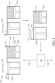
- FIG. 1 schematically depicts an exemplary powder bed jetting process 100 used in making a metal bond abrasive article.
- a layer 138 of loose powder particles 110 from powder chamber 120a with movable piston 122a is deposited in a confined region 140 in powder chamber 120b with movable piston 122b.
- the layer 138 should be of substantially uniform thickness.
- the thickness of the layer may vary less than 50 microns, preferably less than 30 microns, and more preferably less than 10 microns.
- the layers may have any thickness up to about 1 millimeter, as long as the jetted liquid binder precursor material can bind all the loose powder where it is applied.
- the thickness of the layer is from about 10 microns to about 500 microns, more preferably about 10 microns to about 250 microns, more preferably about 50 microns to about 250 microns, and more preferably from about 100 microns to about 200 microns.
- the loose powder particles comprise higher melting metal particles and abrasive particles.
- the higher melting metal particles may comprise any metal from group 2 through to group 15 of the Periodic Table of the elements, for example. Alloys of these metals, and optionally with one or more elements (e.g., metals and/or non-metals such as carbon, silicon, boron) in groups 1 and 15 of the Periodic Table, may also be used.
- suitable metal particles include powders comprising magnesium, aluminum, iron, titanium, niobium, tungsten, chromium, tantalum, cobalt, nickel, vanadium, zirconium, molybdenum, palladium, platinum, copper, silver, gold, cadmium, tin, indium, tantalum, zinc, alloys of any of the foregoing, and combinations thereof.
- the higher melting metal particles preferably having a melting point of at least about 1100° C, and more preferably at least 1200° C, although lower melting metals may also be used.
- Examples include stainless steel (about 1360-1450°C), nickel (1452°C), steel (1371°C), tungsten (3400°C), chromium (1615°C), Inconel (Ni+Cr+Fe, 1390-1425°C), iron (1530°C), manganese (1245-1260°C), cobalt (1132°C), molybdenum(2625°C), Monel (Ni+Cu, 1300-1350°C), niobium (2470°C), titanium (1670°C), vanadium (1900°C), antimony (1167°C), Nichrome (Ni+Cr, 1400°C), alloys of the foregoing (optionally also including one or more of carbon, silicon, and boron), and combinations thereof. Combinations of two or more different higher melting metal particles may also be used.
- the abrasive particles may comprise any abrasive particle used in the abrasives industry.
- the abrasive particles have a Mohs hardness of at least 4, preferably at least 5, more preferably at least 6, more preferably at least 7, more preferably at least 8, more preferably at least 8.5, and more preferably at least 9.
- the abrasive particles comprise superabrasive particles.
- the term "superabrasive” refers to any abrasive particle having a hardness greater than or equal to that of silicon carbide (e.g., silicon carbide, boron carbide, cubic boron nitride, and diamond).
- suitable abrasive materials include aluminum oxide (e.g., alpha alumina) materials (e.g., fused, heat-treated, ceramic, and/or sintered aluminum oxide materials), silicon carbide, titanium diboride, titanium nitride, boron carbide, tungsten carbide, titanium carbide, aluminum nitride, diamond, cubic boron nitride, garnet, fused alumina-zirconia, sol-gel derived abrasive particles, cerium oxide, zirconium oxide, titanium oxide, and combinations thereof. Examples of sol-gel derived abrasive particles can be found in U.S. Pat. No. 4,314,827 (Leitheiser et al. ); U.S. Pat.
- the abrasive particles may be coated with a metal to facilitate bonding with other metallic components (higher and/or lower melting metal particles and/or infused metal) of the abrasive article; for example, as described in U.S. Pat. Appl. Publ. No. 2008/0187769 A1 (Huzinec ) or U.S. Pat. No. 2,367,404 (Kott ).
- the loose powder particles are preferably sized (e.g., by screening) to have a maximum size of less than or equal to 400 microns, preferably less than or equal to 250 microns, more preferably less than or equal to 200 microns, more preferably less than or equal to 150 microns, less than or equal to 100 microns, or even less than or equal to 80 microns, although larger sizes may also be used.
- the higher melting metal particles, abrasive particles, optional lower melting metal particles, and any optional additional particulate components may have the same or different maximum particle sizes, D 90 , D 50 , and/or D 10 particle size distribution parameters.
- the loose powder particles may optionally further comprise lower melting metal particles (e.g., braze particles).
- the lower melting metal particles preferably have a maximum melting point that is at least 50°C lower (preferably at least 75°C lower, at least 100°C, or even at least 150°C lower) than the lowest melting point of the higher melting metal particles.
- melting point includes all temperatures in a melting temperature range of a material.
- suitable lower melting metal particles include particles of metals such as aluminum (660°C), indium (157°C), brass (905-1083°C), bronze (798-1083°C), silver (961°C), copper (1083°C), gold (1064°C), lead (327°C), magnesium (671°C), nickel (1452°C, if used in conjunction with higher melting point metals), zinc (419°C), tin (232°C), active metal brazes (e.g., InCuAg, TiCuAg, CuAg), alloys of the foregoing, and combinations thereof.
- metals such as aluminum (660°C), indium (157°C), brass (905-1083°C), bronze (798-1083°C), silver (961°C), copper (1083°C), gold (1064°C), lead (327°C), magnesium (671°C), nickel (1452°C, if used in conjunction with higher melting point metals), zinc (419°C), tin (232°C), active metal brazes (e.g., InCuA
- the weight ratio of high melting metal particles and/or optional lower melting metal particles to the abrasive particles ranges from about 10:90 to about 90:10, although this is not a requirement.
- the loose powder particles may optionally further comprise other components such as, for example, pore inducers, fillers, and/or fluxing agent particles.
- pore inducers include glass bubbles and organic particles.
- the lower melting metal particles may also serve as a fluxing agent; for example as described in U.S. Pat. No. 6,858,050 (Palmgren ).
- the loose powder particles may optionally be modified to improve their flowability and the uniformity of the layer spread.
- Methods of improving the powders include agglomeration, spray drying, gas or water atomization, flame forming, granulation, milling, and sieving. Additionally, flow agents such as, for example, fumed silica, nanosilica, stearates, and starch may optionally be added.
- a liquid binder precursor material 170 is jetted by printer 150 onto predetermined region(s) 180 of layer 138.
- the liquid binder precursor material thus coats the loose powder particles in region 180, and is subsequently converted to a binder material that binds the loose powder particles in region 180 to each other.
- the liquid binder precursor material may be any composition that can be converted (e.g., by evaporation, or thermal, chemical, and/or radiation curing (e.g., using UV or visible light)) into a binder material that bonds the loose powder particles together according to the jetted pattern (and ultimate 3-D shape upon multiple repetitions).
- the liquid binder precursor material comprises a liquid vehicle having a polymer dissolved therein.
- the liquid may include one or more of organic solvent and water.
- organic solvents include alcohols (e.g., butanol, ethylene glycol monomethyl ether), ketones, and ethers, preferably having a flash point above 100°C.
- a suitable solvent or solvents will typically depend upon requirements of the specific application, such as desired surface tension and viscosity, the selected particulate solid, for example.
- the liquid vehicle can be entirely water, or can contain water in combination with one or more organic solvents.
- the aqueous vehicle contains, on a total weight basis, at least 20 percent water, at least 30 percent water, at least 40 percent water, at least 50 percent water, or even at least 75 percent water.
- one or more organic solvents may be included in the liquid vehicle, for instance, to control drying speed of the liquid vehicle, to control surface tension of the liquid vehicle, to allow dissolution of an ingredient (e.g., of a surfactant), or, as a minor component of any of the ingredients; e.g., an organic co-solvent may be present in a surfactant added as an ingredient to the liquid vehicle.
- an ingredient e.g., of a surfactant
- an organic co-solvent may be present in a surfactant added as an ingredient to the liquid vehicle.
- Exemplary organic solvents include: alcohols such as methyl alcohol, ethyl alcohol, n-propyl alcohol, isopropyl alcohol, n-butyl alcohol, sec-butyl alcohol, t-butyl alcohol, and isobutyl alcohol; ketones or ketoalcohols such as acetone, methyl ethyl ketone, and diacetone alcohol; esters such as ethyl acetate and ethyl lactate; polyhydric alcohols such as ethylene glycol, diethylene glycol, triethylene glycol, propylene glycol, butylene glycol, 1,4-butanediol, 1,2,4-butanetriol, 1,5-pentanediol, 1,2,6-hexanetriol, hexylene glycol, glycerol, glycerol ethoxylate, trimethylolpropane ethoxylate; lower alkyl ethers such as ethylene glycol methyl or ethyl
- the amounts of organic solvent and/or water within the liquid vehicle can depend on a number of factors, such as the particularly desired properties of the liquid binder precursor material such as the viscosity, surface tension, and/or drying rate, which can in turn depend on factors such as the type of ink jet printing technology intended to be used with the liquid vehicle ink, such as piezo-type or thermal-type printheads, for example.
- the liquid binder precursor material may include a polymer that is soluble or dispersible in the liquid vehicle.
- suitable polymers may include polyvinyl pyrrolidones, polyvinyl caprolactams, polyvinyl alcohols, polyacrylamides, poly(2-ethyl-2-oxazoline) (PEOX), polyvinyl butyrate, copolymers of methyl vinyl ether and maleic anhydride, certain copolymers of acrylic acid and/or hydroxyethyl acrylate, methyl cellulose, natural polymers (e.g., dextrin, guar gum, xanthan gum).
- PEOX poly(2-ethyl-2-oxazoline)
- polyvinyl butyrate copolymers of methyl vinyl ether and maleic anhydride
- acrylic acid and/or hydroxyethyl acrylate methyl cellulose
- natural polymers e.g., dextrin, guar gum, xanthan gum.
- the liquid binder precursor material may include one or more free-radically polymerizable or otherwise radiation-curable materials; for example, acrylic monomers and/or oligomers and/or epoxy resins.
- An effective amount of photoinitiator and/or photocatalysts for curing the free-radically polymerizable or otherwise radiation-curable materials may also be included.
- suitable (meth)acrylate monomers and oligomers and otherwise radiation-curable materials e.g., epoxy resins
- suitable (meth)acrylate monomers and oligomers and otherwise radiation-curable materials can be found in, for example, U.S. Pat. No. 5,766,277 (DeVoe et al. ).
- the liquid binder precursor material is essentially free of (e.g., contains less than 1 percent, less than 0.1 percent, less than 0.01 percent, or is even free of) inorganic components (other than water) that would not be volatilized during sintering of the higher and/or lower melting metal particles.
- the liquid binder precursor material may be free of metal nanoparticles and/or metal oxide nanoparticles, if desired.
- nanoparticles refers to particles having an average particle diameter of less than or equal to one micron; for example less than or equal to 500 nanometers (nm), or even less than or equal to 150 nm.
- the jetted liquid binder precursor material 170 is converted (step 190) into a binder material that bonds together the loose powder particles in at least one predetermined region of the loose powder particles to form a layer of bonded powder particles; for example, by evaporation of a liquid vehicle in the liquid binder precursor material.
- heating the binder material to sufficiently high temperature causes it to volatilize and/or decompose (e.g., "burn out") during subsequent sintering or infusion steps.
- step 185) The above steps are then repeated (step 185) with changes to the region where jetting is carried out according to a predetermined design resulting through repetition, layer on layer, in a three-dimensional (3-D) abrasive article preform.
- the loose powder particles and the liquid binder precursor material may be independently selected; that is, either or both or the loose powder particles and the liquid binder precursor material may be the same as, or different from those in adjacent deposited layers.
- the abrasive article preform comprises the bonded powder particles and remaining loose powder particles. Once sufficient repetitions have been carried out to form the abrasive article preform, it is preferably separated from substantially all (e.g., at least 85 percent, at least 90 percent, preferably at least 95 percent, and more preferably at least 99 percent) of the remaining loose powder particles, although this is not a requirement.
- metal bond abrasive wheel 600 has two regions 610, 620. Each region has abrasive particles 630, 640 retained in a metal bond matrix material 650, 660, respectively.
- the abrasive article preform is then heated (step 195 in FIG. 1 ) to remove any organic binder material and/or solvent that may be present, and sinter the metal particles, thereby providing the metal bond abrasive article.
- the abrasive article preform may be heated sufficiently to cause the lower melting metal particles to soften/melt and bond to at least a portion of the loose powder particles, and then cooled to provide the metal bond abrasive article.
- the abrasive article preform may be heated sufficiently to cause the higher melting metal particles to at least sinter and bond to at least a portion of the loose powder particles, and then cooled to provide the metal bond abrasive article.
- Cooling may be accomplished by any means known to the art; for example cold quenching or air cooling to room temperature.
- Metal bond abrasive articles and/or abrasive article preforms made according to the present disclosure may comprise a porous metal-containing matrix (e.g., which may comprise metal particles and abrasive particles, and which may be sintered) with considerable porosity throughout its volume, although this is not a requirement.
- the porous metal-containing matrix may have a void fraction of 1 to 60 volume percent, preferably 5 to 50 volume percent, and more preferably 15 to 50 volume percent, more preferably 40 to 50 volume percent, although this is not a requirement.
- the abrasive article preform may then be infused with a molten metal that has a temperature below the melting point(s) of any other metallic components, then cooled.
- suitable metals that can be made molten and infused into the abrasive article preform include aluminum, indium, brass, bronze, silver, copper, gold, lead, cobalt, magnesium, nickel, zinc, tin, iron, chromium, silicon alloys, alloys of the foregoing, and combinations thereof.
- Powder bed jetting equipment suitable for practicing the present disclosure is commercially available, for example, from ExOne, North Huntington, Pennsylvania.
- Metal bond abrasive articles preparable according to methods of the present disclosure include essentially any known metal bond abrasive article; for example, abrasive pads, grinding bits, abrasive segments, and abrasive wheels.
- the metal bond abrasive article comprises at least a portion of a rotary dental tool (e.g., a dental drill bit, a dental bur, or a dental polishing tool).
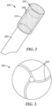
- An exemplary dental bur 200 is shown in FIG. 2 . Referring now to FIG. 2 , dental bur 200 includes head 230 secured to shank 220. Dental bur 200 comprises abrasive particles 205 secured in porous metal bond 210.
- cooling channels having tortuous and or arcuate paths can be readily manufactured using methods of the present disclosure. Cooling channels are open to the exterior of the metal bond abrasive article. In some embodiments, they have a single opening, but more typically they have two or more openings.
- a cooling medium e.g., air, water or oil
- exemplary metal bond abrasive wheel 300 has arcuate and cooling channels 320.
- exemplary metal bond abrasive wheel 400 (shown in FIG. 4 ) has tortuous cooling channels 420.
- FIG. 5 shows an exemplary metal bond abrasive segment 500.
- multiple metal bond abrasive segments 500 are mounted evenly spaced along the circumference of a metal disc to form an abrasive wheel.
- Metal bond abrasive wheels can be prepared by sintering corresponding green bodies (i.e., having the same general shape features, but comprising metal bond precursor particles held together by a temporary binder).
- a print material 400 g was prepared by mixing, based on the mixture weight, 89% of PDR1, and 11% of PDR2.
- the print material was filled into the build box of an X1-Lab 3D printer obtained from The ExOne Company, North Huntingdon, Pennsylvania.
- the binder supply bottle of the printer was filled with BIN.
- the powder bed including the object and surrounding powder was removed from the printer, and placed into an ambient atmosphere oven to cure for 2 hours at 195°C.
- the printed and hardened object was removed from the powder bed and loose powder was removed using a soft bristle brush.
- the segment object was then infiltrated with bronze as follows.
- the object was placed onto capillary stems in a 3D-printed cup, made of PDR1 and made according to the manufacturer's guidelines, filled with BRO1.
- This cup including the object and infiltrant BRO 1, was placed in a furnace and heated with the following protocol: vacuum was applied in the furnace for 10 min at 23°C, after which the furnace was filled with nitrogen and the temperature was ramped at 10°C/min to 250°C and held for 10 min, then ramped at 10°C/min to 420°C and held for 30 min, after that, the temperature was ramped at 10°C/min to 630°C and held for 90 min, then ramped at 5°C/min to 1100°C and held for 1 min, then ramped at 2°C/min to 1125°C and held for 90 min.
- the binder was burned out, and the bronze melted and moved through the capillary stems to infiltrate the printed segment object.
- the furnace was then cooled down to 23°C at 10°C/min. After returning to room temperature, the cup with the attached infiltrated object was removed from the furnace, and the object was removed from the stems.
- the resulting abrasive segment is shown in FIG. 5 and had the dimensions of 2.5 cm length x 2.5 cm width of the outer (largest) surface and 0.6 cm thickness.
- the abrasive segment was tested for abrasive function as follows. The object was fixed in a vise. A rotating steel milling cutter was urged against the abrasive segment. The development of smoke and generation of heat was readily observed when the milling cutter and abrasive segment came into contact. Visual inspection revealed that the cutting edge and flutes of the steel tool were heavily abraded as a result of the contact with the infiltrated abrasive segment.
- a print material 400 g was prepared by mixing, based on the mixture weight, 70% of PDR1, 11% of PDR2, and 19% of BRO2.
- the print material was filled into the build box of an X1-Lab 3D printer obtained from The ExOne Company.
- the binder supply bottle of the printer was filled with BIN.
- the printed and hardened disk was then extracted from the powder bed and loose powder was removed using a soft bristle brush.
- the resulting abrasive article was a flat diamond cutting disc with a 22 mm outer diameter, a 1.5 mm diameter center hole and a 0.6 mm thickness.
- the disk was placed within a bed of PDR4 in a graphite crucible.
- the crucible was then placed in a furnace and heated under a nitrogen atmosphere with the heating protocol as described in Example 1. After cooling to 23°C, it was observed that the bronze had melted and bound the stainless steel and diamond grain to form a porous but stable part. The part had shrunk by approximately 3% as measured by comparing the diameter of the disk before and after heating using a digital caliper.
- a print material 400 g was prepared by mixing, based on the mixture weight, 45% of PDR1, 25% of PDR3, and 30% of BRO2.
- the print material was filled into the build box of an X1-Lab 3D printer obtained from The ExOne Company.
- the binder supply bottle of the printer was filled with BIN.
- the powder mixture spread well and formed uniform, flat layers.
- the powder bed including the object and surrounding powder was removed from the printer, and placed into an ambient atmosphere oven to cure for 2 hours at 195°C.
- the printed and hardened dental bur head precursor was then extracted from the powder bed and loose powder was removed using a soft bristle brush.
- a 3 mm diameter x 40 mm length, stainless steel shank was inserted into the dental bur head.
- the resulting assembly was immersed in PDR4 and placed in a furnace and heated under a nitrogen atmosphere with the protocol below: vacuum was applied in a furnace for 10 min at 23°C, after which the furnace was filled with nitrogen. Then the vacuum was applied again for 10 min at 23°C, and the furnace was filled with nitrogen and temperature was ramped at 5°C/min to 500°C and held for 60 min, then ramped at 2°C/min to 600°C and held for 90 min, after that, the temperature was ramped at 2.5°C/min to 1000°C and held for 1 min, then ramped at 2°C/min to 1 120°C and held for 90 min.
- the dental bur of Example 3 was inserted into a Dremel drill which was in a test fixture that allowed to push the bur against a test coupon at a controlled force.
- the test coupon was a block of Filtek Supreme Ultra Universal dental restorative composite material, (3M ESPE, Saint Paul, Minnesota), which was cast into a block 15 by 25 by 1.8 mm in size, and light cured for 20 seconds exposure of each of the 2 major surfaces, using a UV-Vis LED Source model CF2000 (Clearstone Tech, Hopkins, Minnesota) set at 84 power.
- a thermocouple was attached to one major surface of the test coupon.
- the drill was set to a rotational speed of 10000 RPM and the force was set to 200 gf.
- the bur was moved against the major surface of the coupon opposite the thermocouple for 60 seconds and the temperature rise was recorded after 0, 30 , 45 and 60 seconds, respectively. It was observed that the bur removed material and created a notch. The bur was removed and viewed at 100x magnification using scanning electron microscopy (SEM). It was observed that there was no swarf buildup on the bur.
- SEM scanning electron microscopy
- Table 2 shows a temperature during abrading for the dental burs of Example 3 and the comparative bur (model 840 11 055 MED FLTE Cylin) in the above procedure. Reduced heating correlates with reduced thermal damage to a living tooth during abrading. TABLE 2 DURATION OF ABRADING, seconds TEMPERATURE, °C DENTAL BUR OF EXAMPLE 3 COMPARATIVE DENTAL BUR, model 840 11 055 MED FLTE Cylin 0 25.0 25.0 30 37.0 37.0 45 40.0 42.0 60 42.5 46.0
Landscapes
- Engineering & Computer Science (AREA)
- Mechanical Engineering (AREA)
- Chemical & Material Sciences (AREA)
- Manufacturing & Machinery (AREA)
- Materials Engineering (AREA)
- Health & Medical Sciences (AREA)
- Ceramic Engineering (AREA)
- Inorganic Chemistry (AREA)
- Metallurgy (AREA)
- Organic Chemistry (AREA)
- Oral & Maxillofacial Surgery (AREA)
- Life Sciences & Earth Sciences (AREA)
- Animal Behavior & Ethology (AREA)
- General Health & Medical Sciences (AREA)
- Public Health (AREA)
- Veterinary Medicine (AREA)
- Epidemiology (AREA)
- Dentistry (AREA)
- Polishing Bodies And Polishing Tools (AREA)
Description
- The present disclosure broadly relates to methods of making abrasive articles having abrasive particles in a metallic bonding matrix, such as the method disclosed in
DE 199 09 882 A1 . - Traditionally, metal bond abrasive articles are made by mixing an abrasive grit, such as diamond, aluminum oxide, cubic boron nitride (cBN), or other abrasive grains with a non-melting metal powder (e.g., tungsten, stainless steel, or others), a melting metal powder (e.g., bronze or copper), or a combination thereof. Pore inducers, temporary binders and other additives may be added. The mixture is then introduced into a mold that has been coated with a mold release agent. The filled mold is then compressed in a press to form a molded green body. The green body then is ejected from the mold and subsequently heated in a furnace at high temperature to melt a portion of the metal composition, or it is infused with a molten metal. The heating is typically done in a suitable controlled atmosphere of inert or reducing gas (e.g., nitrogen, argon, hydrogen) or vacuum.
- There are many disadvantages to this manufacturing approach: each abrasive article shape requires a specialized mold; the molds typically are expensive and have a long lead time to make; any design change requires the manufacture of a new mold; there are limitations to the shapes that can be molded, complicated shapes with undercuts or internal structures such as cooling channels are generally not possible; molds wear out and have a limited number of units that can be manufactured per mold; while the molds are filled with the abrasive mixture, separation of the components can occur, leading to inhomogeneous abrasive components and density variation, which is easily visible; and the process is manual and labor intensive.
- Powder bed binder jetting is an additive manufacturing, or "3D printing" technology, in which a thin layer of a powder is temporarily bonded at desired locations by a jetted liquid binder mixture. Typically, that binder mixture is dispensed by an inkjet printing head, and consists of a polymer dissolved in a suitable solvent or carrier solution. In one method, the binder is a powder which is mixed with the other powder, or coated onto the powder and dried, and then an activating liquid, such as water or a solvent mixture, is jetted onto the powder, activating the binder in select areas.
- The printed powder layer is then at least partially dried and lowered so that a next powder layer can be spread. The powder spreading, bonding and drying processes can be repeated until the full object is created. The object and surrounding powder is removed from the printer and often dried or cured to impart additional strength so that the now hardened object can be extracted from the surrounding powder.
- The present invention overcomes the disadvantages of the prior art by methods of making metal bond abrasive articles according to independent claim 1 or to independent claim 6. Preferred embodiments are defined in the dependent claims.
- Advantageously, methods according to the present disclosure are suitable for making metal bond abrasive articles, either in large volume or short run production.
- Features and advantages of the present disclosure will be further understood upon consideration of the detailed description as well as the appended claims.
-
-
FIG. 1 is a schematic process flow diagram of a method of making a metal bond abrasive article according to the present disclosure. -
FIG. 2 is a schematic perspective view of an exemplarydental bur 200 preparable according a method of the present disclosure. -
FIG. 3 is a schematic cross-sectional top view of an exemplary metal bondabrasive wheel 300 preparable according to the present disclosure. -
FIG. 4 is a schematic cross-sectional top view of an exemplary metal bondabrasive wheel 400 preparable according to the present disclosure. -
FIG. 5 is a schematic perspective view of an exemplary metal bondabrasive segment 500. -
FIG. 6 is a schematic perspective view of an exemplary metal bondabrasive wheel 600. - Methods of making a metal bond abrasive articles according to the present invention include a common additive subprocess. The subprocess comprises sequentially, preferably consecutively (although not required) carrying out at least three steps.
-
FIG. 1 schematically depicts an exemplary powderbed jetting process 100 used in making a metal bond abrasive article. - In the first step, a
layer 138 ofloose powder particles 110 frompowder chamber 120a withmovable piston 122a is deposited in a confinedregion 140 inpowder chamber 120b with movable piston 122b. Thelayer 138 should be of substantially uniform thickness. For example, the thickness of the layer may vary less than 50 microns, preferably less than 30 microns, and more preferably less than 10 microns. The layers may have any thickness up to about 1 millimeter, as long as the jetted liquid binder precursor material can bind all the loose powder where it is applied. Preferably, the thickness of the layer is from about 10 microns to about 500 microns, more preferably about 10 microns to about 250 microns, more preferably about 50 microns to about 250 microns, and more preferably from about 100 microns to about 200 microns. - The loose powder particles comprise higher melting metal particles and abrasive particles.
- The higher melting metal particles may comprise any metal from group 2 through to group 15 of the Periodic Table of the elements, for example. Alloys of these metals, and optionally with one or more elements (e.g., metals and/or non-metals such as carbon, silicon, boron) in groups 1 and 15 of the Periodic Table, may also be used. Examples of suitable metal particles include powders comprising magnesium, aluminum, iron, titanium, niobium, tungsten, chromium, tantalum, cobalt, nickel, vanadium, zirconium, molybdenum, palladium, platinum, copper, silver, gold, cadmium, tin, indium, tantalum, zinc, alloys of any of the foregoing, and combinations thereof.
- The higher melting metal particles preferably having a melting point of at least about 1100° C, and more preferably at least 1200° C, although lower melting metals may also be used. Examples include stainless steel (about 1360-1450°C), nickel (1452°C), steel (1371°C), tungsten (3400°C), chromium (1615°C), Inconel (Ni+Cr+Fe, 1390-1425°C), iron (1530°C), manganese (1245-1260°C), cobalt (1132°C), molybdenum(2625°C), Monel (Ni+Cu, 1300-1350°C), niobium (2470°C), titanium (1670°C), vanadium (1900°C), antimony (1167°C), Nichrome (Ni+Cr, 1400°C), alloys of the foregoing (optionally also including one or more of carbon, silicon, and boron), and combinations thereof. Combinations of two or more different higher melting metal particles may also be used.
- The abrasive particles may comprise any abrasive particle used in the abrasives industry. Preferably, the abrasive particles have a Mohs hardness of at least 4, preferably at least 5, more preferably at least 6, more preferably at least 7, more preferably at least 8, more preferably at least 8.5, and more preferably at least 9. In certain embodiments, the abrasive particles comprise superabrasive particles. As used herein, the term "superabrasive" refers to any abrasive particle having a hardness greater than or equal to that of silicon carbide (e.g., silicon carbide, boron carbide, cubic boron nitride, and diamond).
- Specific examples of suitable abrasive materials include aluminum oxide (e.g., alpha alumina) materials (e.g., fused, heat-treated, ceramic, and/or sintered aluminum oxide materials), silicon carbide, titanium diboride, titanium nitride, boron carbide, tungsten carbide, titanium carbide, aluminum nitride, diamond, cubic boron nitride, garnet, fused alumina-zirconia, sol-gel derived abrasive particles, cerium oxide, zirconium oxide, titanium oxide, and combinations thereof. Examples of sol-gel derived abrasive particles can be found in
U.S. Pat. No. 4,314,827 (Leitheiser et al. );U.S. Pat. No. 4,623,364 (Cottringer et al. );U.S. Pat. No. 4,744,802 (Schwabel );U.S. Pat. No. 4,770,671 (Monroe et al. ); andU.S. Pat. No. 4,881,951 (Monroe et al. ). Agglomerate abrasive particles that comprise finer abrasive particles in a vitreous bond matrix (e.g., as described inU.S. Pat. No. 6,551,366 (D'Souza et al. )) may also be used. - The abrasive particles may be coated with a metal to facilitate bonding with other metallic components (higher and/or lower melting metal particles and/or infused metal) of the abrasive article; for example, as described in
U.S. Pat. Appl. Publ. No. 2008/0187769 A1 (Huzinec ) orU.S. Pat. No. 2,367,404 (Kott ). - In order to achieve fine resolution, the loose powder particles are preferably sized (e.g., by screening) to have a maximum size of less than or equal to 400 microns, preferably less than or equal to 250 microns, more preferably less than or equal to 200 microns, more preferably less than or equal to 150 microns, less than or equal to 100 microns, or even less than or equal to 80 microns, although larger sizes may also be used. The higher melting metal particles, abrasive particles, optional lower melting metal particles, and any optional additional particulate components may have the same or different maximum particle sizes, D90, D50, and/or D10 particle size distribution parameters.
- The loose powder particles may optionally further comprise lower melting metal particles (e.g., braze particles). The lower melting metal particles preferably have a maximum melting point that is at least 50°C lower (preferably at least 75°C lower, at least 100°C, or even at least 150°C lower) than the lowest melting point of the higher melting metal particles. As used herein, the term "melting point" includes all temperatures in a melting temperature range of a material. Examples of suitable lower melting metal particles include particles of metals such as aluminum (660°C), indium (157°C), brass (905-1083°C), bronze (798-1083°C), silver (961°C), copper (1083°C), gold (1064°C), lead (327°C), magnesium (671°C), nickel (1452°C, if used in conjunction with higher melting point metals), zinc (419°C), tin (232°C), active metal brazes (e.g., InCuAg, TiCuAg, CuAg), alloys of the foregoing, and combinations thereof.
- Typically, the weight ratio of high melting metal particles and/or optional lower melting metal particles to the abrasive particles ranges from about 10:90 to about 90:10, although this is not a requirement.
- The loose powder particles may optionally further comprise other components such as, for example, pore inducers, fillers, and/or fluxing agent particles. Examples of pore inducers include glass bubbles and organic particles. In some embodiments, the lower melting metal particles may also serve as a fluxing agent; for example as described in
U.S. Pat. No. 6,858,050 (Palmgren ). - The loose powder particles may optionally be modified to improve their flowability and the uniformity of the layer spread. Methods of improving the powders include agglomeration, spray drying, gas or water atomization, flame forming, granulation, milling, and sieving. Additionally, flow agents such as, for example, fumed silica, nanosilica, stearates, and starch may optionally be added.
- Next, a liquid
binder precursor material 170 is jetted byprinter 150 onto predetermined region(s) 180 oflayer 138. The liquid binder precursor material thus coats the loose powder particles inregion 180, and is subsequently converted to a binder material that binds the loose powder particles inregion 180 to each other. The liquid binder precursor material may be any composition that can be converted (e.g., by evaporation, or thermal, chemical, and/or radiation curing (e.g., using UV or visible light)) into a binder material that bonds the loose powder particles together according to the jetted pattern (and ultimate 3-D shape upon multiple repetitions). - In some embodiments, the liquid binder precursor material comprises a liquid vehicle having a polymer dissolved therein. The liquid may include one or more of organic solvent and water. Exemplary organic solvents include alcohols (e.g., butanol, ethylene glycol monomethyl ether), ketones, and ethers, preferably having a flash point above 100°C.
- Selection of a suitable solvent or solvents will typically depend upon requirements of the specific application, such as desired surface tension and viscosity, the selected particulate solid, for example.
- The liquid vehicle can be entirely water, or can contain water in combination with one or more organic solvents. Preferably, the aqueous vehicle contains, on a total weight basis, at least 20 percent water, at least 30 percent water, at least 40 percent water, at least 50 percent water, or even at least 75 percent water.
- In some embodiments, one or more organic solvents may be included in the liquid vehicle, for instance, to control drying speed of the liquid vehicle, to control surface tension of the liquid vehicle, to allow dissolution of an ingredient (e.g., of a surfactant), or, as a minor component of any of the ingredients; e.g., an organic co-solvent may be present in a surfactant added as an ingredient to the liquid vehicle. Exemplary organic solvents include: alcohols such as methyl alcohol, ethyl alcohol, n-propyl alcohol, isopropyl alcohol, n-butyl alcohol, sec-butyl alcohol, t-butyl alcohol, and isobutyl alcohol; ketones or ketoalcohols such as acetone, methyl ethyl ketone, and diacetone alcohol; esters such as ethyl acetate and ethyl lactate; polyhydric alcohols such as ethylene glycol, diethylene glycol, triethylene glycol, propylene glycol, butylene glycol, 1,4-butanediol, 1,2,4-butanetriol, 1,5-pentanediol, 1,2,6-hexanetriol, hexylene glycol, glycerol, glycerol ethoxylate, trimethylolpropane ethoxylate; lower alkyl ethers such as ethylene glycol methyl or ethyl ether, diethylene glycol ethyl ether, triethylene glycol methyl or ethyl ether, ethylene glycol n-butyl ether, diethylene glycol n-butyl ether, diethylene glycol methyl ether, ethylene glycol phenyl ether, propylene glycol methyl ether, dipropylene glycol methyl ether, tripropylene glycol methyl ether, propylene glycol methyl ether acetate, dipropylene glycol methyl ether acetate, propylene glycol n-propyl ether, dipropylene glycol n-propyl ether, tripropylene glycol n-propyl ether, propylene glycol n-butyl ether, dipropylene glycol n-butyl ether, tripropylene glycol n-butyl ether, propylene glycol phenyl ether, and dipropylene glycol dimethyl ether; nitrogen-containing compounds such as 2-pyrrolidinone and N-methyl-2-pyrrolidinone; sulfur-containing compounds such as dimethyl sulfoxide, tetramethylene sulfone, and thioglycol; and combinations of any of the foregoing.
- The amounts of organic solvent and/or water within the liquid vehicle can depend on a number of factors, such as the particularly desired properties of the liquid binder precursor material such as the viscosity, surface tension, and/or drying rate, which can in turn depend on factors such as the type of ink jet printing technology intended to be used with the liquid vehicle ink, such as piezo-type or thermal-type printheads, for example.
- The liquid binder precursor material may include a polymer that is soluble or dispersible in the liquid vehicle. Examples of suitable polymers may include polyvinyl pyrrolidones, polyvinyl caprolactams, polyvinyl alcohols, polyacrylamides, poly(2-ethyl-2-oxazoline) (PEOX), polyvinyl butyrate, copolymers of methyl vinyl ether and maleic anhydride, certain copolymers of acrylic acid and/or hydroxyethyl acrylate, methyl cellulose, natural polymers (e.g., dextrin, guar gum, xanthan gum). Of these, polyvinyl pyrrolidones are preferred for use with liquid vehicles that are predominantly water. Other organic polymers than those listed above may be used instead or in addition if desired.
- The liquid binder precursor material may include one or more free-radically polymerizable or otherwise radiation-curable materials; for example, acrylic monomers and/or oligomers and/or epoxy resins. An effective amount of photoinitiator and/or photocatalysts for curing the free-radically polymerizable or otherwise radiation-curable materials may also be included. Examples of suitable (meth)acrylate monomers and oligomers and otherwise radiation-curable materials (e.g., epoxy resins) can be found in, for example,
U.S. Pat. No. 5,766,277 (DeVoe et al. ). - In some preferred embodiments, the liquid binder precursor material is essentially free of (e.g., contains less than 1 percent, less than 0.1 percent, less than 0.01 percent, or is even free of) inorganic components (other than water) that would not be volatilized during sintering of the higher and/or lower melting metal particles. The liquid binder precursor material may be free of metal nanoparticles and/or metal oxide nanoparticles, if desired. As used herein, the term "nanoparticles" refers to particles having an average particle diameter of less than or equal to one micron; for example less than or equal to 500 nanometers (nm), or even less than or equal to 150 nm.
- Referring again to
FIG. 1 , the jetted liquidbinder precursor material 170 is converted (step 190) into a binder material that bonds together the loose powder particles in at least one predetermined region of the loose powder particles to form a layer of bonded powder particles; for example, by evaporation of a liquid vehicle in the liquid binder precursor material. In these embodiments, heating the binder material to sufficiently high temperature causes it to volatilize and/or decompose (e.g., "burn out") during subsequent sintering or infusion steps. - The above steps are then repeated (step 185) with changes to the region where jetting is carried out according to a predetermined design resulting through repetition, layer on layer, in a three-dimensional (3-D) abrasive article preform. In each repetition, the loose powder particles and the liquid binder precursor material may be independently selected; that is, either or both or the loose powder particles and the liquid binder precursor material may be the same as, or different from those in adjacent deposited layers.
- The abrasive article preform comprises the bonded powder particles and remaining loose powder particles. Once sufficient repetitions have been carried out to form the abrasive article preform, it is preferably separated from substantially all (e.g., at least 85 percent, at least 90 percent, preferably at least 95 percent, and more preferably at least 99 percent) of the remaining loose powder particles, although this is not a requirement.
- If desired, multiple particle reservoirs each containing a different powder may be used. Likewise, multiple different liquid binder precursor materials may be used, either through a common printhead or, preferably, through separate printheads. This results in different powders/binders distributed in different and discrete regions of the metal bond abrasive article. For example, relatively inexpensive, but lower performing abrasive particles, metal powders, and or binder materials may be relegated to regions of the metal bond abrasive article where it is not particularly important to have high performance properties (e.g., in the interior away from the abrading surface). Referring now to
FIG. 6 , metal bondabrasive wheel 600 has tworegions abrasive particles bond matrix material - The abrasive article preform is then heated (
step 195 inFIG. 1 ) to remove any organic binder material and/or solvent that may be present, and sinter the metal particles, thereby providing the metal bond abrasive article. - Further details concerning powder bed jetting techniques suitable for practicing the present disclosure can be found, for example, in
U.S. Pat. Nos. 5,340,656 (Sachs et al. ) and6,403,002 B1 (van der Geest ). - In embodiments in which the loose powder particles include higher melting metal particles and lower melting metal particles, the abrasive article preform may be heated sufficiently to cause the lower melting metal particles to soften/melt and bond to at least a portion of the loose powder particles, and then cooled to provide the metal bond abrasive article.
- In embodiments in which the loose powder particles include higher melting metal particles and no lower melting metal particles, the abrasive article preform may be heated sufficiently to cause the higher melting metal particles to at least sinter and bond to at least a portion of the loose powder particles, and then cooled to provide the metal bond abrasive article.
- Cooling may be accomplished by any means known to the art; for example cold quenching or air cooling to room temperature.
- Metal bond abrasive articles and/or abrasive article preforms made according to the present disclosure may comprise a porous metal-containing matrix (e.g., which may comprise metal particles and abrasive particles, and which may be sintered) with considerable porosity throughout its volume, although this is not a requirement. For example, the porous metal-containing matrix may have a void fraction of 1 to 60 volume percent, preferably 5 to 50 volume percent, and more preferably 15 to 50 volume percent, more preferably 40 to 50 volume percent, although this is not a requirement. Accordingly, the abrasive article preform may then be infused with a molten metal that has a temperature below the melting point(s) of any other metallic components, then cooled. Examples of suitable metals that can be made molten and infused into the abrasive article preform include aluminum, indium, brass, bronze, silver, copper, gold, lead, cobalt, magnesium, nickel, zinc, tin, iron, chromium, silicon alloys, alloys of the foregoing, and combinations thereof.
- Powder bed jetting equipment suitable for practicing the present disclosure is commercially available, for example, from ExOne, North Huntington, Pennsylvania.
- Further details concerning sintering and then infusing with molten metal can be found in, for example,
U.S. Pat. No. 2,367,404 (Kott ) andU.S. Pat. Appln. Publ. No. 2002/095875 (D'Evelyn et al. ). - Metal bond abrasive articles preparable according to methods of the present disclosure include essentially any known metal bond abrasive article; for example, abrasive pads, grinding bits, abrasive segments, and abrasive wheels. In some preferred embodiments, the metal bond abrasive article comprises at least a portion of a rotary dental tool (e.g., a dental drill bit, a dental bur, or a dental polishing tool). An exemplary
dental bur 200 is shown inFIG. 2 . Referring now toFIG. 2 ,dental bur 200 includeshead 230 secured toshank 220.Dental bur 200 comprisesabrasive particles 205 secured inporous metal bond 210. - During fabrication and testing of such a dental bur (e.g., see Example 3 hereinbelow) according to the present disclosure, it was discovered that reduced swarf buildup during use can be achieved when the bur has sufficient porosity. Although the initial cut rate may be somewhat reduced it is still more than adequate, and the decline in cut rate due to swarf build up is greatly reduced.
- Advantageously, methods according to the present disclosure are suitable for manufacturing various metal bond abrasive articles that cannot be readily or easily fabricated by other methods. For example, inclusion of internal voids is possible as long as an opening to the exterior of the abrasive preform exists for removal of unbonded loose powder. Accordingly, cooling channels having tortuous and or arcuate paths can be readily manufactured using methods of the present disclosure. Cooling channels are open to the exterior of the metal bond abrasive article. In some embodiments, they have a single opening, but more typically they have two or more openings. A cooling medium (e.g., air, water or oil) circulates through the cooling channel(s) to remove heat generated during abrading.
- Referring now to
FIG. 3 , exemplary metal bondabrasive wheel 300 has arcuate and coolingchannels 320. Similarly, exemplary metal bond abrasive wheel 400 (shown inFIG. 4 ) hastortuous cooling channels 420. -
FIG. 5 shows an exemplary metal bondabrasive segment 500. In typical use, multiple metal bondabrasive segments 500 are mounted evenly spaced along the circumference of a metal disc to form an abrasive wheel. - Metal bond abrasive wheels can be prepared by sintering corresponding green bodies (i.e., having the same general shape features, but comprising metal bond precursor particles held together by a temporary binder).
- Objects and advantages of this disclosure are further illustrated by the following non-limiting examples, but the particular materials and amounts thereof recited in these examples, as well as other conditions and details, should not be construed to unduly limit this invention, which is defined by the claims.
- Unless otherwise noted, all parts, percentages, ratios, etc. in the Examples and the rest of the specification are by weight. In the Examples: °C = degrees Celsius, g = grams, min = minute, mm = millimeter, sec = second, and rpm = revolutions per minute.
Table 1, below, lists abbreviations for materials used in the Examples.TABLE 1 ABBREVIATION DESCRIPTION PDR1 PM-R1-S4-30 stainless steel powder from The ExOne Company, North Huntingdon, Pennsylvania PDR2 CMD, 200/230 Mesh, D76 diamond powder from Pinnacle Abrasives, Santa Rosa, California PDR3 LS00 270/325 diamond powder from Lands Superabrasives Co., New York, New York PDR4 DURALUM SPECIAL WHITE 60 grit aluminum oxide powder from Washington Mills Electro Minerals, Niagara Falls, New York BIN Ether solvent-based polymer binder, obtained as PM-B-SR1-04 from The ExOne Company, North Huntingdon, Pennsylvania BRO1 PM-I-R1 bronze powder from The ExOne Company, North Huntingdon, Pennsylvania BRO2 LS431155LO/Cu226020/1 bronze powder (Cu80/Sn20, maximum particle size 53 micron) from Goodfellow Cambridge Limited, Huntington, England BRO3 FINE SPHERICAL BRONZE POWDER - GRADE 80/20 bronze powder (Cu80/Sn20) with max particle size 53 micron, from Foxmet S.A., Dondelange, Luxembourg - A print material (400 g) was prepared by mixing, based on the mixture weight, 89% of PDR1, and 11% of PDR2. The print material was filled into the build box of an X1-Lab 3D printer obtained from The ExOne Company, North Huntingdon, Pennsylvania. The binder supply bottle of the printer was filled with BIN. 3D printing was executed using printing protocol and procedures according to the manufacturer's operating instructions using the following operation parameters for stainless steel: layer height = 100 microns, spreader speed = 25 mm/sec, printing saturation = 70% level, and drying time = 60 sec at 90% heater power. During the printing process, the powder mixture spread well and formed uniform, flat layers. The diamond grains looked evenly distributed. After printing finished, the powder bed, including the object and surrounding powder was removed from the printer, and placed into an ambient atmosphere oven to cure for 2 hours at 195°C. The printed and hardened object was removed from the powder bed and loose powder was removed using a soft bristle brush.
- The segment object was then infiltrated with bronze as follows. The object was placed onto capillary stems in a 3D-printed cup, made of PDR1 and made according to the manufacturer's guidelines, filled with BRO1. This cup, including the object and infiltrant BRO 1, was placed in a furnace and heated with the following protocol: vacuum was applied in the furnace for 10 min at 23°C, after which the furnace was filled with nitrogen and the temperature was ramped at 10°C/min to 250°C and held for 10 min, then ramped at 10°C/min to 420°C and held for 30 min, after that, the temperature was ramped at 10°C/min to 630°C and held for 90 min, then ramped at 5°C/min to 1100°C and held for 1 min, then ramped at 2°C/min to 1125°C and held for 90 min. In this process, the binder was burned out, and the bronze melted and moved through the capillary stems to infiltrate the printed segment object. The furnace was then cooled down to 23°C at 10°C/min. After returning to room temperature, the cup with the attached infiltrated object was removed from the furnace, and the object was removed from the stems.
- The resulting abrasive segment is shown in
FIG. 5 and had the dimensions of 2.5 cm length x 2.5 cm width of the outer (largest) surface and 0.6 cm thickness. The abrasive segment was tested for abrasive function as follows. The object was fixed in a vise. A rotating steel milling cutter was urged against the abrasive segment. The development of smoke and generation of heat was readily observed when the milling cutter and abrasive segment came into contact. Visual inspection revealed that the cutting edge and flutes of the steel tool were heavily abraded as a result of the contact with the infiltrated abrasive segment. - A print material (400 g) was prepared by mixing, based on the mixture weight, 70% of PDR1, 11% of PDR2, and 19% of BRO2. The print material was filled into the build box of an X1-Lab 3D printer obtained from The ExOne Company. The binder supply bottle of the printer was filled with BIN. 3D printing was executed using printing protocol and procedures according to the manufacturer's operating instructions using the following operation parameters for stainless steel: layer height = 100 microns, spreader speed = 5 mm/sec, printing saturation = 100% level, and drying time = 60 sec at 90% heater power. After the printing finished, the powder bed, including the object and surrounding powder was removed from the printer, and placed into an ambient atmosphere oven to cure for 2 hours at 195°C. After cooling to 23°C, the printed and hardened disk was then extracted from the powder bed and loose powder was removed using a soft bristle brush. The resulting abrasive article was a flat diamond cutting disc with a 22 mm outer diameter, a 1.5 mm diameter center hole and a 0.6 mm thickness.
- The disk was placed within a bed of PDR4 in a graphite crucible. The crucible was then placed in a furnace and heated under a nitrogen atmosphere with the heating protocol as described in Example 1. After cooling to 23°C, it was observed that the bronze had melted and bound the stainless steel and diamond grain to form a porous but stable part. The part had shrunk by approximately 3% as measured by comparing the diameter of the disk before and after heating using a digital caliper.
- A print material (400 g) was prepared by mixing, based on the mixture weight, 45% of PDR1, 25% of PDR3, and 30% of BRO2. The print material was filled into the build box of an X1-Lab 3D printer obtained from The ExOne Company. The binder supply bottle of the printer was filled with BIN. 3D printing was executed using printing protocol and procedures to print a dental bur head precursor part in the shape of
dental bur head 210 inFIG. 2 (outer diameter = 5 mm, inner diameter = 3 mm) according to the manufacturer's operating instructions using the following operation parameters for stainless steel: layer height = 200 microns, spreader speed = 5 mm/sec, printing saturation = 120% level, and drying time = 120 sec at 90% heater power. The powder mixture spread well and formed uniform, flat layers. The diamond grains looked evenly distributed. After the print process finished, the powder bed, including the object and surrounding powder was removed from the printer, and placed into an ambient atmosphere oven to cure for 2 hours at 195°C. After cooling to 23°C, the printed and hardened dental bur head precursor was then extracted from the powder bed and loose powder was removed using a soft bristle brush. - A 3 mm diameter x 40 mm length, stainless steel shank was inserted into the dental bur head. The resulting assembly was immersed in PDR4 and placed in a furnace and heated under a nitrogen atmosphere with the protocol below: vacuum was applied in a furnace for 10 min at 23°C, after which the furnace was filled with nitrogen. Then the vacuum was applied again for 10 min at 23°C, and the furnace was filled with nitrogen and temperature was ramped at 5°C/min to 500°C and held for 60 min, then ramped at 2°C/min to 600°C and held for 90 min, after that, the temperature was ramped at 2.5°C/min to 1000°C and held for 1 min, then ramped at 2°C/min to 1 120°C and held for 90 min. The furnace then was allowed to cool down to 23°C and the resultant dental bur shown in
FIG. 2 was removed (dental bur head: outer diameter = 5 mm, inner diameter = 3 mm). Following heat treatment, the head was fully adhered to the shank. The porosity of the dental bur head was measured using a pycnometer (ACCUPYC 1330 from Micrometrics Corporation, Norcross, Georgia) and found to be 43%. - The dental bur of Example 3 was inserted into a Dremel drill which was in a test fixture that allowed to push the bur against a test coupon at a controlled force. The test coupon was a block of Filtek Supreme Ultra Universal dental restorative composite material, (3M ESPE, Saint Paul, Minnesota), which was cast into a block 15 by 25 by 1.8 mm in size, and light cured for 20 seconds exposure of each of the 2 major surfaces, using a UV-Vis LED Source model CF2000 (Clearstone Tech, Hopkins, Minnesota) set at 84 power. A thermocouple was attached to one major surface of the test coupon. The drill was set to a rotational speed of 10000 RPM and the force was set to 200 gf. The bur was moved against the major surface of the coupon opposite the thermocouple for 60 seconds and the temperature rise was recorded after 0, 30 , 45 and 60 seconds, respectively. It was observed that the bur removed material and created a notch. The bur was removed and viewed at 100x magnification using scanning electron microscopy (SEM). It was observed that there was no swarf buildup on the bur.
- The procedure was repeated using a comparative commercially available dental bur (model 840 11 055 MED FLTE Cylin, 100 micron diamond, from Brasseler USA, Savannah, Georgia) having the same outer diameter. Comparing SEM images of this comparative bur before and after the abrading, it was observed that there was significant visible swarf buildup on the comparative bur (model 840 11 055 MED FLTE Cylin).
- Table 2 shows a temperature during abrading for the dental burs of Example 3 and the comparative bur (model 840 11 055 MED FLTE Cylin) in the above procedure. Reduced heating correlates with reduced thermal damage to a living tooth during abrading.
TABLE 2 DURATION OF ABRADING, seconds TEMPERATURE, °C DENTAL BUR OF EXAMPLE 3 COMPARATIVE DENTAL BUR, model 840 11 055 MED FLTE Cylin 0 25.0 25.0 30 37.0 37.0 45 40.0 42.0 60 42.5 46.0
Claims (10)
- A method of making a metal bond abrasive article (200, 300, 400, 500, 600), the method comprising the sequential steps:a) a subprocess comprising sequentially:i) depositing a layer (138) of loose powder particles (110) in a confined region (140), wherein the loose powder particles (110) comprise higher melting metal particles and abrasive particles, and wherein the layer (138) of loose powder particles (110) has substantially uniform thickness;ii) jetting a liquid binder precursor material (170) onto at least one predetermined region (180) of the layer (138) of loose powder particles (110);iii) converting (190) the liquid binder precursor material (170) into a binder material that bonds together the loose powder particles in the at least one predetermined region (180) to form a layer of bonded powder particles;b) independently carrying out step a) a plurality of times (185) to generate an abrasive article preform comprising the bonded powder particles and remaining loose powder particles, wherein the abrasive article preform has a predetermined shape, and wherein in each step a), the loose powder particles (110) are independently selected, and the liquid binder precursor material (170) is independently selected;c) separating substantially all of the remaining loose powder particles from the abrasive article preform;d) infusing the abrasive article preform with a molten lower melting metal, wherein at least some of the higher melting metal particles do not completely melt when contacted by the molten lower melting metal; ande) solidifying the molten lower melting metal to provide the metal bond abrasive article.
- The method of claim 1, wherein the loose powder particles (110) further comprise fluxing agent particles.
- The method of claim 1 or 2, wherein the metal bond abrasive article includes at least one cooling channel (320, 420).
- The method of any one of claims 1 to 3, wherein the metal bond abrasive article is selected from the group consisting of an abrasive pad, an abrasive grinding bit, abrasive segments (500), and an abrasive wheel (300, 400, 600).
- The method of any one of claims 1 to 3, wherein the metal bond abrasive article comprises at least a portion of a rotary dental tool (200).
- A method of making a metal bond abrasive article (200, 300, 400, 500, 600), the method comprising sequential steps:a) a subprocess comprising sequentially:i) depositing a layer (138) of loose powder particles (110) in a confined region (140), wherein the loose powder particles (110) comprise metal particles and abrasive particles, and wherein the layer (138) of loose powder particles (110) has substantially uniform thickness;ii) jetting a liquid binder precursor material (170) onto at least one predetermined region (180) of the layer (138) of loose powder particles (110);iii) converting (190) the liquid binder precursor material (170) into a binder material that bonds together the loose powder particles in the at least one predetermined region (180) to form bonded powder particles;b) independently carrying out step a) a plurality of times (185) to generate an abrasive article preform comprising the bonded powder particles and remaining loose powder particles, wherein the abrasive article preform has a predetermined shape, and wherein in each step a), the loose powder particles (110) are independently selected, and the liquid binder precursor material (170) is independently selected;c) separating substantially all of the remaining loose powder particles from the abrasive article preform; andd) heating the abrasive article preform to provide the metal bond abrasive article.
- The method of claim 6, wherein the loose powder particles (110) further comprise fluxing agent particles.
- The method of claim 6 or 7, wherein the metal bond abrasive article includes at least one cooling channel (320, 420).
- The method of any one of claims 6 to 8, wherein the metal bond abrasive article is selected from the group consisting of an abrasive pad, an abrasive grinding bit, abrasive segments (500), and an abrasive wheel (300, 400, 600).
- The method of any one of claims 6 to 9, wherein the metal bond abrasive article comprises at least a portion of a rotary dental tool (200).
Applications Claiming Priority (2)
| Application Number | Priority Date | Filing Date | Title |
|---|---|---|---|
| US201562184689P | 2015-06-25 | 2015-06-25 | |
| PCT/US2016/037767 WO2016209696A1 (en) | 2015-06-25 | 2016-06-16 | Methods of making metal bond abrasive articles and metal bond abrasive articles |
Publications (3)
| Publication Number | Publication Date |
|---|---|
| EP3313617A1 EP3313617A1 (en) | 2018-05-02 |
| EP3313617A4 EP3313617A4 (en) | 2019-02-27 |
| EP3313617B1 true EP3313617B1 (en) | 2023-06-14 |
Family
ID=57586133
Family Applications (1)
| Application Number | Title | Priority Date | Filing Date |
|---|---|---|---|
| EP16815079.5A Active EP3313617B1 (en) | 2015-06-25 | 2016-06-16 | Methods of making metal bond abrasive articles and metal bond abrasive articles |
Country Status (6)
| Country | Link |
|---|---|
| US (2) | US10888973B2 (en) |
| EP (1) | EP3313617B1 (en) |
| JP (1) | JP6987643B2 (en) |
| CN (1) | CN107896491B (en) |
| PL (1) | PL3313617T3 (en) |
| WO (1) | WO2016209696A1 (en) |
Families Citing this family (26)
| Publication number | Priority date | Publication date | Assignee | Title |
|---|---|---|---|---|
| EP4011923B1 (en) | 2016-01-21 | 2024-08-28 | 3M Innovative Properties Company | Methods of making metal bond and vitreous bond abrasive articles |
| CN108778741A (en) * | 2016-03-30 | 2018-11-09 | 3M创新有限公司 | Method of making metal bonded and glassy bonded abrasive articles and abrasive article precursors |
| CN108015906A (en) | 2016-10-28 | 2018-05-11 | 圣戈班磨料磨具有限公司 | Hollow drill bit and its manufacture method |
| US11623324B2 (en) | 2016-12-23 | 2023-04-11 | 3M Innovative Properties Company | Polymer bond abrasive articles and methods of making them |
| CN110337347B (en) * | 2017-02-28 | 2022-07-12 | 3M创新有限公司 | Metal bond abrasive article and method of making a metal bond abrasive article |
| US11338363B2 (en) | 2017-06-28 | 2022-05-24 | Hewlett-Packard Development Company, L.P. | Three-dimensional printing |
| US11404180B2 (en) * | 2017-10-09 | 2022-08-02 | Ut-Battelle, Llc | Method for producing collimators and other components from neutron absorbing materials using additive manufacturing |
| US10654259B2 (en) * | 2017-10-24 | 2020-05-19 | Global Circuit Innovations Incorporated | Conductive diamond application method |
| WO2020102025A1 (en) | 2018-11-12 | 2020-05-22 | Desktop Metal, Inc. | Techniques for controlling build material flow characteristics in additive manufacturing and related systems and methods |
| US12179421B2 (en) * | 2019-04-27 | 2024-12-31 | Hewlett-Packard Development Company, L.P. | Three-dimensional printing |
| US11538597B2 (en) * | 2019-06-28 | 2022-12-27 | Ut-Battelle, Llc | Additive manufacturing of composite neutron absorbing components |
| CN112140015A (en) | 2019-06-28 | 2020-12-29 | 圣戈班磨料磨具有限公司 | Abrasive article and method of forming the same |
| WO2021001730A1 (en) * | 2019-07-02 | 2021-01-07 | 3M Innovative Properties Company | Methods of making metal bond abrasive articles and metal bond abrasive articles |
| EP3785825A1 (en) * | 2019-08-30 | 2021-03-03 | 3M Innovative Properties Company | Powder blend for use in additive manufacturing |
| US20220389277A1 (en) | 2019-10-28 | 2022-12-08 | 3M Innovative Properties Company | System and methods of finishing a metallic surface |
| EP4072783A4 (en) * | 2019-12-10 | 2024-04-24 | Saint-gobain Abrasives, Inc | Fixed abrasive article |
| EP4072782B1 (en) | 2019-12-12 | 2026-01-28 | 3M Innovative Properties Company | Polymer bond abrasive articles including continuous polymer matrix, and methods of making same |
| CN110948407B (en) * | 2019-12-13 | 2022-05-17 | 黄石海纳新材料科技股份有限公司 | Preparation method of grinding tool |
| US11319613B2 (en) | 2020-08-18 | 2022-05-03 | Enviro Metals, LLC | Metal refinement |
| JP2024509813A (en) | 2021-03-05 | 2024-03-05 | サンーゴバン アブレイシブズ,インコーポレイティド | Abrasive article and method for forming the same |
| US12473475B2 (en) | 2021-03-05 | 2025-11-18 | Saint-Gobain Abrasives, Inc. | Abrasive articles and methods for forming same |
| CN118591435A (en) * | 2021-12-30 | 2024-09-03 | 圣戈班磨料磨具有限公司 | Abrasive article and method of forming the same |
| EP4457058A4 (en) | 2021-12-30 | 2026-01-07 | Saint Gobain Abrasives Inc | Grinding articles and methods for shaping them |
| JP7782271B2 (en) * | 2022-01-19 | 2025-12-09 | セイコーエプソン株式会社 | Method for manufacturing three-dimensional object and three-dimensional object |
| CN114932223B (en) * | 2022-06-07 | 2024-01-09 | 江苏精研科技股份有限公司 | Co-sintering preparation method of metal matrix composite |
| US20240325129A1 (en) * | 2023-03-29 | 2024-10-03 | Kabushiki Kaisha Shofu | Dental polishing instrument |
Citations (3)
| Publication number | Priority date | Publication date | Assignee | Title |
|---|---|---|---|---|
| WO2001034371A2 (en) * | 1999-11-05 | 2001-05-17 | Z Corporation | Material systems and methods of three-dimensional printing |
| EP1278615B1 (en) * | 2000-05-03 | 2005-11-16 | Saint-Gobain Abrasives, Inc. | Method to produce a patterned abrasive tool using a rapid prototype technique for the master tool |
| EP1661690A1 (en) * | 2003-08-27 | 2006-05-31 | Fuji Photo Film Co., Ltd. | Method of producing three-dimensional model |
Family Cites Families (73)
| Publication number | Priority date | Publication date | Assignee | Title |
|---|---|---|---|---|
| US2367404A (en) | 1943-07-09 | 1945-01-16 | Fish Schurman Corp | Abrasive composition of matter and method of forming same |
| US4314827A (en) | 1979-06-29 | 1982-02-09 | Minnesota Mining And Manufacturing Company | Non-fused aluminum oxide-based abrasive mineral |
| US4623364A (en) | 1984-03-23 | 1986-11-18 | Norton Company | Abrasive material and method for preparing the same |
| US4574003A (en) | 1984-05-03 | 1986-03-04 | Minnesota Mining And Manufacturing Co. | Process for improved densification of sol-gel produced alumina-based ceramics |
| US4718005A (en) | 1984-05-03 | 1988-01-05 | International Business Machines Corporation | Distributed control of alias name usage in networks |
| US5227104A (en) | 1984-06-14 | 1993-07-13 | Norton Company | High solids content gels and a process for producing them |
| CA1254238A (en) | 1985-04-30 | 1989-05-16 | Alvin P. Gerk | Process for durable sol-gel produced alumina-based ceramics, abrasive grain and abrasive products |
| US4770671A (en) | 1985-12-30 | 1988-09-13 | Minnesota Mining And Manufacturing Company | Abrasive grits formed of ceramic containing oxides of aluminum and yttrium, method of making and using the same and products made therewith |
| AU613584B2 (en) * | 1986-09-15 | 1991-08-08 | Abrasive Technology N.A. Inc. | A flexible abrasive coated article and method of making it |
| US4960441A (en) | 1987-05-11 | 1990-10-02 | Norton Company | Sintered alumina-zirconia ceramic bodies |
| US4881951A (en) | 1987-05-27 | 1989-11-21 | Minnesota Mining And Manufacturing Co. | Abrasive grits formed of ceramic containing oxides of aluminum and rare earth metal, method of making and products made therewith |
| US5011508A (en) | 1988-10-14 | 1991-04-30 | Minnesota Mining And Manufacturing Company | Shelling-resistant abrasive grain, a method of making the same, and abrasive products |
| JPH02237759A (en) * | 1989-03-10 | 1990-09-20 | Sanwa Daiyamondo Kogyo Kk | Cutter and manufacture thereof |
| US5204055A (en) | 1989-12-08 | 1993-04-20 | Massachusetts Institute Of Technology | Three-dimensional printing techniques |
| US5387380A (en) | 1989-12-08 | 1995-02-07 | Massachusetts Institute Of Technology | Three-dimensional printing techniques |
| US5449388A (en) * | 1990-05-21 | 1995-09-12 | Wiand; Ronald C. | Injection molded abrasive article and process |
| US5139978A (en) | 1990-07-16 | 1992-08-18 | Minnesota Mining And Manufacturing Company | Impregnation method for transformation of transition alumina to a alpha alumina |
| US5090968A (en) | 1991-01-08 | 1992-02-25 | Norton Company | Process for the manufacture of filamentary abrasive particles |
| US5178849A (en) | 1991-03-22 | 1993-01-12 | Norton Company | Process for manufacturing alpha alumina from dispersible boehmite |
| JPH04372366A (en) * | 1991-06-17 | 1992-12-25 | I N R Kenkyusho:Kk | Grinding tool and manufacture thereof |
| JP2835210B2 (en) | 1991-06-19 | 1998-12-14 | 古河電気工業株式会社 | Heating furnace for soldering |
| US5252264A (en) | 1991-11-08 | 1993-10-12 | Dtm Corporation | Apparatus and method for producing parts with multi-directional powder delivery |
| US5178644A (en) | 1992-01-23 | 1993-01-12 | Cincinnati Milacron Inc. | Method for making vitreous bonded abrasive article and article made by the method |
| US5282875A (en) | 1992-03-18 | 1994-02-01 | Cincinnati Milacron Inc. | High density sol-gel alumina-based abrasive vitreous bonded grinding wheel |
| US5366523A (en) | 1992-07-23 | 1994-11-22 | Minnesota Mining And Manufacturing Company | Abrasive article containing shaped abrasive particles |
| US5201916A (en) | 1992-07-23 | 1993-04-13 | Minnesota Mining And Manufacturing Company | Shaped abrasive particles and method of making same |
| JP3052603B2 (en) * | 1992-09-17 | 2000-06-19 | 三菱マテリアル株式会社 | Porous metal bond whetstone |
| WO1994007969A1 (en) | 1992-09-25 | 1994-04-14 | Minnesota Mining And Manufacturing Company | Abrasive grain including rare earth oxide therein |
| EP0662072B1 (en) | 1992-09-25 | 1997-04-02 | Minnesota Mining And Manufacturing Company | Abrasive grain containing alumina and zirconia |
| DE69302582T2 (en) | 1992-09-25 | 1996-10-31 | Minnesota Mining & Mfg | METHOD FOR PRODUCING ALUMINUM OXIDE AND CEROXIDE-CONTAINING GRINDING GRAIN |
| US5490882A (en) * | 1992-11-30 | 1996-02-13 | Massachusetts Institute Of Technology | Process for removing loose powder particles from interior passages of a body |
| BR9408462A (en) | 1993-12-28 | 1997-08-26 | Minnesota Mining & Mfg | Specified nominal type of abrasive grain and abrasive article |
| US6209420B1 (en) | 1994-03-16 | 2001-04-03 | Baker Hughes Incorporated | Method of manufacturing bits, bit components and other articles of manufacture |
| US5839329A (en) | 1994-03-16 | 1998-11-24 | Baker Hughes Incorporated | Method for infiltrating preformed components and component assemblies |
| JPH0811051A (en) * | 1994-06-28 | 1996-01-16 | Sony Corp | Polishing cloth |
| US5725162A (en) | 1995-04-05 | 1998-03-10 | Saint Gobain/Norton Industrial Ceramics Corporation | Firing sol-gel alumina particles |
| US5660621A (en) * | 1995-12-29 | 1997-08-26 | Massachusetts Institute Of Technology | Binder composition for use in three dimensional printing |
| US5776214A (en) | 1996-09-18 | 1998-07-07 | Minnesota Mining And Manufacturing Company | Method for making abrasive grain and abrasive articles |
| US5766277A (en) | 1996-09-20 | 1998-06-16 | Minnesota Mining And Manufacturing Company | Coated abrasive article and method of making same |
| NL1006059C2 (en) | 1997-05-14 | 1998-11-17 | Geest Adrianus F Van Der | Method and device for manufacturing a shaped body. |
| DE19834559A1 (en) * | 1998-07-31 | 2000-02-03 | Friedrich Schiller Uni Jena Bu | Surface finishing, especially grinding, lapping and polishing, tool manufacturing method by use of rapid prototyping methods |
| DE19909882C2 (en) * | 1999-03-06 | 2002-01-10 | Fraunhofer Ges Forschung | Material for the layer-by-layer production of tools, molds or components using the laser sintering process |
| US6645412B2 (en) | 1999-04-20 | 2003-11-11 | Stratasys, Inc. | Process of making a three-dimensional object |
| US6123744A (en) | 1999-06-02 | 2000-09-26 | Milacron Inc. | Vitreous bond compositions for abrasive articles |
| US6376590B2 (en) | 1999-10-28 | 2002-04-23 | 3M Innovative Properties Company | Zirconia sol, process of making and composite material |
| US6551366B1 (en) | 2000-11-10 | 2003-04-22 | 3M Innovative Properties Company | Spray drying methods of making agglomerate abrasive grains and abrasive articles |
| US20020095875A1 (en) | 2000-12-04 | 2002-07-25 | D'evelyn Mark Philip | Abrasive diamond composite and method of making thereof |
| US6575353B2 (en) | 2001-02-20 | 2003-06-10 | 3M Innovative Properties Company | Reducing metals as a brazing flux |
| US6593391B2 (en) * | 2001-03-27 | 2003-07-15 | General Electric Company | Abrasive-filled thermoset composition and its preparation, and abrasive-filled articles and their preparation |
| DE10361895B4 (en) * | 2003-12-30 | 2013-02-07 | Technische Universität Kaiserslautern | High-performance grinding wheel |
| US8870571B2 (en) | 2004-09-24 | 2014-10-28 | Spectrum Systems, Llc | Rotary dental tool and method of manufacture |
| US7867302B2 (en) | 2005-02-22 | 2011-01-11 | Saint-Gobain Abrasives, Inc. | Rapid tooling system and methods for manufacturing abrasive articles |
| US7875091B2 (en) * | 2005-02-22 | 2011-01-25 | Saint-Gobain Abrasives, Inc. | Rapid tooling system and methods for manufacturing abrasive articles |
| US7524345B2 (en) | 2005-02-22 | 2009-04-28 | Saint-Gobain Abrasives, Inc. | Rapid tooling system and methods for manufacturing abrasive articles |
| US20070020457A1 (en) | 2005-07-21 | 2007-01-25 | 3M Innovative Properties Company | Composite particle comprising an abrasive grit |
| US7399330B2 (en) | 2005-10-18 | 2008-07-15 | 3M Innovative Properties Company | Agglomerate abrasive grains and methods of making the same |
| EP2001656B1 (en) | 2006-04-06 | 2014-10-15 | 3D Systems Incorporated | KiT FOR THE PRODUCTION OF THREE-DIMENSIONAL OBJECTS BY USE OF ELECTROMAGNETIC RADIATION |
| US20080187769A1 (en) | 2006-04-13 | 2008-08-07 | 3M Innovative Properties | Metal-coated superabrasive material and methods of making the same |
| US10040216B2 (en) | 2007-04-04 | 2018-08-07 | The Exone Company | Powder particle layerwise three-dimensional printing process |
| MX2011001443A (en) * | 2008-08-08 | 2011-04-11 | Saint Gobain Abrasives Inc | Abrasive tools having a continuous metal phase for bonding an abrasive component to a carrier. |
| FR2939075B1 (en) | 2008-12-01 | 2010-12-17 | Rhodia Operations | REALIZATION OF ARTICLE BY SELECTIVE FUSION OF POLYMER POWDER LAYERS |
| US8991211B1 (en) | 2009-11-01 | 2015-03-31 | The Exone Company | Three-dimensional printing glass articles |
| FR2955330B1 (en) | 2010-01-19 | 2012-01-20 | Arkema France | THERMOPLASTIC POWDER COMPOSITION AND THREE-DIMENSIONAL ARTICLES MADE BY SINKING SUCH A COMPOSITION |
| CN101804603B (en) | 2010-04-29 | 2012-05-30 | 沈阳理工大学 | Tin-bonded diamond abrasive biomimetic polishing disc and manufacturing method |
| TWI613285B (en) | 2010-09-03 | 2018-02-01 | 聖高拜磨料有限公司 | Bonded abrasive article and forming method |
| US9156999B2 (en) * | 2011-07-28 | 2015-10-13 | Hewlett-Packard Development Company, L.P. | Liquid inkjettable materials for three-dimensional printing |
| FR2979269B1 (en) | 2011-08-24 | 2014-05-16 | Lorraine Inst Nat Polytech | PROCESS FOR MANUFACTURING A WORKPIECE COMPRISING ALUMINUM |
| US9067299B2 (en) | 2012-04-25 | 2015-06-30 | Applied Materials, Inc. | Printed chemical mechanical polishing pad |
| CN105050770B (en) | 2013-03-12 | 2018-08-17 | 3M创新有限公司 | Bonded abrasive article |
| CN105102158B (en) | 2013-04-05 | 2018-03-23 | 3M创新有限公司 | Sintered abrasive grain particle, its preparation method and the abrasive product for including sintered abrasive grain particle |
| CN111978921A (en) | 2013-09-30 | 2020-11-24 | 圣戈本陶瓷及塑料股份有限公司 | Shaped abrasive particles and methods of forming the same |
| KR102081045B1 (en) | 2013-12-31 | 2020-02-26 | 생-고뱅 어브레이시브즈, 인코포레이티드 | Abrasive article including shaped abrasive particles |
| CN107787264B (en) | 2015-06-25 | 2020-10-13 | 3M创新有限公司 | Vitreous bonded abrasive article and method of making same |
-
2016
- 2016-06-16 JP JP2017566775A patent/JP6987643B2/en active Active
- 2016-06-16 CN CN201680037153.0A patent/CN107896491B/en active Active
- 2016-06-16 WO PCT/US2016/037767 patent/WO2016209696A1/en not_active Ceased
- 2016-06-16 US US15/573,254 patent/US10888973B2/en active Active
- 2016-06-16 PL PL16815079.5T patent/PL3313617T3/en unknown
- 2016-06-16 EP EP16815079.5A patent/EP3313617B1/en active Active
-
2020
- 2020-12-11 US US17/247,442 patent/US11597058B2/en active Active
Patent Citations (3)
| Publication number | Priority date | Publication date | Assignee | Title |
|---|---|---|---|---|
| WO2001034371A2 (en) * | 1999-11-05 | 2001-05-17 | Z Corporation | Material systems and methods of three-dimensional printing |
| EP1278615B1 (en) * | 2000-05-03 | 2005-11-16 | Saint-Gobain Abrasives, Inc. | Method to produce a patterned abrasive tool using a rapid prototype technique for the master tool |
| EP1661690A1 (en) * | 2003-08-27 | 2006-05-31 | Fuji Photo Film Co., Ltd. | Method of producing three-dimensional model |
Also Published As
| Publication number | Publication date |
|---|---|
| JP6987643B2 (en) | 2022-01-05 |
| WO2016209696A1 (en) | 2016-12-29 |
| PL3313617T3 (en) | 2023-08-14 |
| CN107896491A (en) | 2018-04-10 |
| JP2018519176A (en) | 2018-07-19 |
| CN107896491B (en) | 2020-12-29 |
| EP3313617A4 (en) | 2019-02-27 |
| US20210094149A1 (en) | 2021-04-01 |
| US20180126515A1 (en) | 2018-05-10 |
| EP3313617A1 (en) | 2018-05-02 |
| US10888973B2 (en) | 2021-01-12 |
| US11597058B2 (en) | 2023-03-07 |
Similar Documents
| Publication | Publication Date | Title |
|---|---|---|
| US11597058B2 (en) | Methods of making metal bond abrasive articles and metal bond abrasive articles | |
| EP3313614B1 (en) | Methods of making vitreous bond abrasive articles | |
| US11383350B2 (en) | Metal bond abrasive articles and methods of making metal bond abrasive articles | |
| EP4011923B1 (en) | Methods of making metal bond and vitreous bond abrasive articles | |
| WO2021001730A1 (en) | Methods of making metal bond abrasive articles and metal bond abrasive articles | |
| US20230219195A1 (en) | Polymer bond abrasive articles and methods of making them | |
| KR102427116B1 (en) | Bonded Abrasive Article Comprising Oriented Abrasive Particles, and Method of Making the Same | |
| EP3221087B1 (en) | Bonded abrasive articles and methods of manufacture | |
| JP2019513087A (en) | METHOD FOR PRODUCING METAL BOND AND VIBROUS BOND Abrasive Article, AND Abrasive Article Precursor | |
| US20220266421A1 (en) | Abrasive articles having internal coolant features and methods of manufacturing the same |
Legal Events
| Date | Code | Title | Description |
|---|---|---|---|
| STAA | Information on the status of an ep patent application or granted ep patent |
Free format text: STATUS: THE INTERNATIONAL PUBLICATION HAS BEEN MADE |
|
| PUAI | Public reference made under article 153(3) epc to a published international application that has entered the european phase |
Free format text: ORIGINAL CODE: 0009012 |
|
| STAA | Information on the status of an ep patent application or granted ep patent |
Free format text: STATUS: REQUEST FOR EXAMINATION WAS MADE |
|
| 17P | Request for examination filed |
Effective date: 20180104 |
|
| AK | Designated contracting states |
Kind code of ref document: A1 Designated state(s): AL AT BE BG CH CY CZ DE DK EE ES FI FR GB GR HR HU IE IS IT LI LT LU LV MC MK MT NL NO PL PT RO RS SE SI SK SM TR |
|
| AX | Request for extension of the european patent |
Extension state: BA ME |
|
| DAV | Request for validation of the european patent (deleted) | ||
| DAX | Request for extension of the european patent (deleted) | ||
| A4 | Supplementary search report drawn up and despatched |
Effective date: 20190128 |
|
| RIC1 | Information provided on ipc code assigned before grant |
Ipc: A61C 3/06 20060101ALI20190122BHEP Ipc: A61C 3/02 20060101ALI20190122BHEP Ipc: B24D 18/00 20060101AFI20190122BHEP Ipc: B22F 3/00 20060101ALI20190122BHEP Ipc: B33Y 10/00 20150101ALI20190122BHEP Ipc: B24D 3/06 20060101ALI20190122BHEP Ipc: B24B 1/04 20060101ALI20190122BHEP Ipc: B24D 3/28 20060101ALI20190122BHEP |
|
| STAA | Information on the status of an ep patent application or granted ep patent |
Free format text: STATUS: EXAMINATION IS IN PROGRESS |
|
| 17Q | First examination report despatched |
Effective date: 20220511 |
|
| REG | Reference to a national code |
Ref country code: DE Ref legal event code: R079 Free format text: PREVIOUS MAIN CLASS: B24D0018000000 Ipc: B22F0003260000 Ref document number: 602016080369 Country of ref document: DE |
|
| GRAP | Despatch of communication of intention to grant a patent |
Free format text: ORIGINAL CODE: EPIDOSNIGR1 |
|
| STAA | Information on the status of an ep patent application or granted ep patent |
Free format text: STATUS: GRANT OF PATENT IS INTENDED |
|
| INTG | Intention to grant announced |
Effective date: 20230203 |
|
| RIC1 | Information provided on ipc code assigned before grant |
Ipc: B33Y 10/00 20150101ALI20230120BHEP Ipc: A61C 3/06 20060101ALI20230120BHEP Ipc: A61C 3/02 20060101ALI20230120BHEP Ipc: B24B 1/04 20060101ALI20230120BHEP Ipc: B24D 18/00 20060101ALI20230120BHEP Ipc: B24D 3/28 20060101ALI20230120BHEP Ipc: B24D 3/06 20060101ALI20230120BHEP Ipc: C22C 33/02 20060101ALI20230120BHEP Ipc: C22C 32/00 20060101ALI20230120BHEP Ipc: C22C 26/00 20060101ALI20230120BHEP Ipc: B33Y 80/00 20150101ALI20230120BHEP Ipc: B22F 5/00 20060101ALI20230120BHEP Ipc: B22F 10/14 20210101ALI20230120BHEP Ipc: B22F 5/10 20060101ALI20230120BHEP Ipc: B22F 3/26 20060101AFI20230120BHEP |
|
| GRAS | Grant fee paid |
Free format text: ORIGINAL CODE: EPIDOSNIGR3 |
|
| GRAA | (expected) grant |
Free format text: ORIGINAL CODE: 0009210 |
|
| STAA | Information on the status of an ep patent application or granted ep patent |
Free format text: STATUS: THE PATENT HAS BEEN GRANTED |
|
| AK | Designated contracting states |
Kind code of ref document: B1 Designated state(s): AL AT BE BG CH CY CZ DE DK EE ES FI FR GB GR HR HU IE IS IT LI LT LU LV MC MK MT NL NO PL PT RO RS SE SI SK SM TR |
|
| REG | Reference to a national code |
Ref country code: CH Ref legal event code: EP |
|
| REG | Reference to a national code |
Ref country code: DE Ref legal event code: R096 Ref document number: 602016080369 Country of ref document: DE |
|
| REG | Reference to a national code |
Ref country code: AT Ref legal event code: REF Ref document number: 1578858 Country of ref document: AT Kind code of ref document: T Effective date: 20230715 |
|
| REG | Reference to a national code |
Ref country code: SE Ref legal event code: TRGR |
|
| P01 | Opt-out of the competence of the unified patent court (upc) registered |
Effective date: 20230817 |
|
| REG | Reference to a national code |
Ref country code: LT Ref legal event code: MG9D |
|
| REG | Reference to a national code |
Ref country code: NL Ref legal event code: MP Effective date: 20230614 |
|
| PG25 | Lapsed in a contracting state [announced via postgrant information from national office to epo] |
Ref country code: NO Free format text: LAPSE BECAUSE OF FAILURE TO SUBMIT A TRANSLATION OF THE DESCRIPTION OR TO PAY THE FEE WITHIN THE PRESCRIBED TIME-LIMIT Effective date: 20230914 Ref country code: ES Free format text: LAPSE BECAUSE OF FAILURE TO SUBMIT A TRANSLATION OF THE DESCRIPTION OR TO PAY THE FEE WITHIN THE PRESCRIBED TIME-LIMIT Effective date: 20230614 |
|
| PG25 | Lapsed in a contracting state [announced via postgrant information from national office to epo] |
Ref country code: RS Free format text: LAPSE BECAUSE OF FAILURE TO SUBMIT A TRANSLATION OF THE DESCRIPTION OR TO PAY THE FEE WITHIN THE PRESCRIBED TIME-LIMIT Effective date: 20230614 Ref country code: NL Free format text: LAPSE BECAUSE OF FAILURE TO SUBMIT A TRANSLATION OF THE DESCRIPTION OR TO PAY THE FEE WITHIN THE PRESCRIBED TIME-LIMIT Effective date: 20230614 Ref country code: LV Free format text: LAPSE BECAUSE OF FAILURE TO SUBMIT A TRANSLATION OF THE DESCRIPTION OR TO PAY THE FEE WITHIN THE PRESCRIBED TIME-LIMIT Effective date: 20230614 Ref country code: LT Free format text: LAPSE BECAUSE OF FAILURE TO SUBMIT A TRANSLATION OF THE DESCRIPTION OR TO PAY THE FEE WITHIN THE PRESCRIBED TIME-LIMIT Effective date: 20230614 Ref country code: HR Free format text: LAPSE BECAUSE OF FAILURE TO SUBMIT A TRANSLATION OF THE DESCRIPTION OR TO PAY THE FEE WITHIN THE PRESCRIBED TIME-LIMIT Effective date: 20230614 Ref country code: GR Free format text: LAPSE BECAUSE OF FAILURE TO SUBMIT A TRANSLATION OF THE DESCRIPTION OR TO PAY THE FEE WITHIN THE PRESCRIBED TIME-LIMIT Effective date: 20230915 |
|
| PG25 | Lapsed in a contracting state [announced via postgrant information from national office to epo] |
Ref country code: FI Free format text: LAPSE BECAUSE OF FAILURE TO SUBMIT A TRANSLATION OF THE DESCRIPTION OR TO PAY THE FEE WITHIN THE PRESCRIBED TIME-LIMIT Effective date: 20230614 |
|
| PG25 | Lapsed in a contracting state [announced via postgrant information from national office to epo] |
Ref country code: SK Free format text: LAPSE BECAUSE OF FAILURE TO SUBMIT A TRANSLATION OF THE DESCRIPTION OR TO PAY THE FEE WITHIN THE PRESCRIBED TIME-LIMIT Effective date: 20230614 |
|
| PG25 | Lapsed in a contracting state [announced via postgrant information from national office to epo] |
Ref country code: IS Free format text: LAPSE BECAUSE OF FAILURE TO SUBMIT A TRANSLATION OF THE DESCRIPTION OR TO PAY THE FEE WITHIN THE PRESCRIBED TIME-LIMIT Effective date: 20231014 |
|
| PG25 | Lapsed in a contracting state [announced via postgrant information from national office to epo] |
Ref country code: SM Free format text: LAPSE BECAUSE OF FAILURE TO SUBMIT A TRANSLATION OF THE DESCRIPTION OR TO PAY THE FEE WITHIN THE PRESCRIBED TIME-LIMIT Effective date: 20230614 Ref country code: SK Free format text: LAPSE BECAUSE OF FAILURE TO SUBMIT A TRANSLATION OF THE DESCRIPTION OR TO PAY THE FEE WITHIN THE PRESCRIBED TIME-LIMIT Effective date: 20230614 Ref country code: RO Free format text: LAPSE BECAUSE OF FAILURE TO SUBMIT A TRANSLATION OF THE DESCRIPTION OR TO PAY THE FEE WITHIN THE PRESCRIBED TIME-LIMIT Effective date: 20230614 Ref country code: PT Free format text: LAPSE BECAUSE OF FAILURE TO SUBMIT A TRANSLATION OF THE DESCRIPTION OR TO PAY THE FEE WITHIN THE PRESCRIBED TIME-LIMIT Effective date: 20231016 Ref country code: IS Free format text: LAPSE BECAUSE OF FAILURE TO SUBMIT A TRANSLATION OF THE DESCRIPTION OR TO PAY THE FEE WITHIN THE PRESCRIBED TIME-LIMIT Effective date: 20231014 Ref country code: EE Free format text: LAPSE BECAUSE OF FAILURE TO SUBMIT A TRANSLATION OF THE DESCRIPTION OR TO PAY THE FEE WITHIN THE PRESCRIBED TIME-LIMIT Effective date: 20230614 Ref country code: CZ Free format text: LAPSE BECAUSE OF FAILURE TO SUBMIT A TRANSLATION OF THE DESCRIPTION OR TO PAY THE FEE WITHIN THE PRESCRIBED TIME-LIMIT Effective date: 20230614 |
|
| REG | Reference to a national code |
Ref country code: CH Ref legal event code: PL |
|
| REG | Reference to a national code |
Ref country code: BE Ref legal event code: MM Effective date: 20230630 |
|
| PG25 | Lapsed in a contracting state [announced via postgrant information from national office to epo] |
Ref country code: LU Free format text: LAPSE BECAUSE OF NON-PAYMENT OF DUE FEES Effective date: 20230616 |
|
| PG25 | Lapsed in a contracting state [announced via postgrant information from national office to epo] |
Ref country code: MC Free format text: LAPSE BECAUSE OF FAILURE TO SUBMIT A TRANSLATION OF THE DESCRIPTION OR TO PAY THE FEE WITHIN THE PRESCRIBED TIME-LIMIT Effective date: 20230614 |
|
| REG | Reference to a national code |
Ref country code: DE Ref legal event code: R097 Ref document number: 602016080369 Country of ref document: DE |
|
| REG | Reference to a national code |
Ref country code: IE Ref legal event code: MM4A |
|
| PG25 | Lapsed in a contracting state [announced via postgrant information from national office to epo] |
Ref country code: MC Free format text: LAPSE BECAUSE OF FAILURE TO SUBMIT A TRANSLATION OF THE DESCRIPTION OR TO PAY THE FEE WITHIN THE PRESCRIBED TIME-LIMIT Effective date: 20230614 Ref country code: LU Free format text: LAPSE BECAUSE OF NON-PAYMENT OF DUE FEES Effective date: 20230616 |
|
| PG25 | Lapsed in a contracting state [announced via postgrant information from national office to epo] |
Ref country code: IE Free format text: LAPSE BECAUSE OF NON-PAYMENT OF DUE FEES Effective date: 20230616 |
|
| PLBE | No opposition filed within time limit |
Free format text: ORIGINAL CODE: 0009261 |
|
| STAA | Information on the status of an ep patent application or granted ep patent |
Free format text: STATUS: NO OPPOSITION FILED WITHIN TIME LIMIT |
|
| PG25 | Lapsed in a contracting state [announced via postgrant information from national office to epo] |
Ref country code: IE Free format text: LAPSE BECAUSE OF NON-PAYMENT OF DUE FEES Effective date: 20230616 Ref country code: DK Free format text: LAPSE BECAUSE OF FAILURE TO SUBMIT A TRANSLATION OF THE DESCRIPTION OR TO PAY THE FEE WITHIN THE PRESCRIBED TIME-LIMIT Effective date: 20230614 Ref country code: CH Free format text: LAPSE BECAUSE OF NON-PAYMENT OF DUE FEES Effective date: 20230630 |
|
| PG25 | Lapsed in a contracting state [announced via postgrant information from national office to epo] |
Ref country code: SI Free format text: LAPSE BECAUSE OF FAILURE TO SUBMIT A TRANSLATION OF THE DESCRIPTION OR TO PAY THE FEE WITHIN THE PRESCRIBED TIME-LIMIT Effective date: 20230614 |
|
| 26N | No opposition filed |
Effective date: 20240315 |
|
| GBPC | Gb: european patent ceased through non-payment of renewal fee |
Effective date: 20230914 |
|
| PG25 | Lapsed in a contracting state [announced via postgrant information from national office to epo] |
Ref country code: SI Free format text: LAPSE BECAUSE OF FAILURE TO SUBMIT A TRANSLATION OF THE DESCRIPTION OR TO PAY THE FEE WITHIN THE PRESCRIBED TIME-LIMIT Effective date: 20230614 Ref country code: IT Free format text: LAPSE BECAUSE OF FAILURE TO SUBMIT A TRANSLATION OF THE DESCRIPTION OR TO PAY THE FEE WITHIN THE PRESCRIBED TIME-LIMIT Effective date: 20230614 Ref country code: BE Free format text: LAPSE BECAUSE OF NON-PAYMENT OF DUE FEES Effective date: 20230630 |
|
| REG | Reference to a national code |
Ref country code: AT Ref legal event code: UEP Ref document number: 1578858 Country of ref document: AT Kind code of ref document: T Effective date: 20230614 |
|
| PG25 | Lapsed in a contracting state [announced via postgrant information from national office to epo] |
Ref country code: GB Free format text: LAPSE BECAUSE OF NON-PAYMENT OF DUE FEES Effective date: 20230914 |
|
| PG25 | Lapsed in a contracting state [announced via postgrant information from national office to epo] |
Ref country code: GB Free format text: LAPSE BECAUSE OF NON-PAYMENT OF DUE FEES Effective date: 20230914 |
|
| PG25 | Lapsed in a contracting state [announced via postgrant information from national office to epo] |
Ref country code: BG Free format text: LAPSE BECAUSE OF FAILURE TO SUBMIT A TRANSLATION OF THE DESCRIPTION OR TO PAY THE FEE WITHIN THE PRESCRIBED TIME-LIMIT Effective date: 20230614 |
|
| PG25 | Lapsed in a contracting state [announced via postgrant information from national office to epo] |
Ref country code: BG Free format text: LAPSE BECAUSE OF FAILURE TO SUBMIT A TRANSLATION OF THE DESCRIPTION OR TO PAY THE FEE WITHIN THE PRESCRIBED TIME-LIMIT Effective date: 20230614 |
|
| PGFP | Annual fee paid to national office [announced via postgrant information from national office to epo] |
Ref country code: PL Payment date: 20250525 Year of fee payment: 10 Ref country code: DE Payment date: 20250520 Year of fee payment: 10 |
|
| PGFP | Annual fee paid to national office [announced via postgrant information from national office to epo] |
Ref country code: FR Payment date: 20250521 Year of fee payment: 10 |
|
| PGFP | Annual fee paid to national office [announced via postgrant information from national office to epo] |
Ref country code: AT Payment date: 20250522 Year of fee payment: 10 |
|
| PG25 | Lapsed in a contracting state [announced via postgrant information from national office to epo] |
Ref country code: CY Free format text: LAPSE BECAUSE OF FAILURE TO SUBMIT A TRANSLATION OF THE DESCRIPTION OR TO PAY THE FEE WITHIN THE PRESCRIBED TIME-LIMIT; INVALID AB INITIO Effective date: 20160616 |
|
| PGFP | Annual fee paid to national office [announced via postgrant information from national office to epo] |
Ref country code: SE Payment date: 20250520 Year of fee payment: 10 |
|
| PG25 | Lapsed in a contracting state [announced via postgrant information from national office to epo] |
Ref country code: HU Free format text: LAPSE BECAUSE OF FAILURE TO SUBMIT A TRANSLATION OF THE DESCRIPTION OR TO PAY THE FEE WITHIN THE PRESCRIBED TIME-LIMIT; INVALID AB INITIO Effective date: 20160616 |
|
| PG25 | Lapsed in a contracting state [announced via postgrant information from national office to epo] |
Ref country code: TR Free format text: LAPSE BECAUSE OF FAILURE TO SUBMIT A TRANSLATION OF THE DESCRIPTION OR TO PAY THE FEE WITHIN THE PRESCRIBED TIME-LIMIT Effective date: 20230614 |