EP3313490B1 - Tubing system - Google Patents
Tubing system Download PDFInfo
- Publication number
- EP3313490B1 EP3313490B1 EP16815404.5A EP16815404A EP3313490B1 EP 3313490 B1 EP3313490 B1 EP 3313490B1 EP 16815404 A EP16815404 A EP 16815404A EP 3313490 B1 EP3313490 B1 EP 3313490B1
- Authority
- EP
- European Patent Office
- Prior art keywords
- breakaway
- sheath
- assembly
- subassembly
- pore
- Prior art date
- Legal status (The legal status is an assumption and is not a legal conclusion. Google has not performed a legal analysis and makes no representation as to the accuracy of the status listed.)
- Active
Links
Images










Classifications
-
- A—HUMAN NECESSITIES
- A61—MEDICAL OR VETERINARY SCIENCE; HYGIENE
- A61M—DEVICES FOR INTRODUCING MEDIA INTO, OR ONTO, THE BODY; DEVICES FOR TRANSDUCING BODY MEDIA OR FOR TAKING MEDIA FROM THE BODY; DEVICES FOR PRODUCING OR ENDING SLEEP OR STUPOR
- A61M39/00—Tubes, tube connectors, tube couplings, valves, access sites or the like, specially adapted for medical use
- A61M39/22—Valves or arrangement of valves
- A61M39/26—Valves closing automatically on disconnecting the line and opening on reconnection thereof
-
- A—HUMAN NECESSITIES
- A61—MEDICAL OR VETERINARY SCIENCE; HYGIENE
- A61M—DEVICES FOR INTRODUCING MEDIA INTO, OR ONTO, THE BODY; DEVICES FOR TRANSDUCING BODY MEDIA OR FOR TAKING MEDIA FROM THE BODY; DEVICES FOR PRODUCING OR ENDING SLEEP OR STUPOR
- A61M39/00—Tubes, tube connectors, tube couplings, valves, access sites or the like, specially adapted for medical use
- A61M39/10—Tube connectors; Tube couplings
- A61M39/1011—Locking means for securing connection; Additional tamper safeties
-
- A—HUMAN NECESSITIES
- A61—MEDICAL OR VETERINARY SCIENCE; HYGIENE
- A61M—DEVICES FOR INTRODUCING MEDIA INTO, OR ONTO, THE BODY; DEVICES FOR TRANSDUCING BODY MEDIA OR FOR TAKING MEDIA FROM THE BODY; DEVICES FOR PRODUCING OR ENDING SLEEP OR STUPOR
- A61M39/00—Tubes, tube connectors, tube couplings, valves, access sites or the like, specially adapted for medical use
- A61M39/10—Tube connectors; Tube couplings
- A61M2039/1027—Quick-acting type connectors
-
- A—HUMAN NECESSITIES
- A61—MEDICAL OR VETERINARY SCIENCE; HYGIENE
- A61M—DEVICES FOR INTRODUCING MEDIA INTO, OR ONTO, THE BODY; DEVICES FOR TRANSDUCING BODY MEDIA OR FOR TAKING MEDIA FROM THE BODY; DEVICES FOR PRODUCING OR ENDING SLEEP OR STUPOR
- A61M39/00—Tubes, tube connectors, tube couplings, valves, access sites or the like, specially adapted for medical use
- A61M39/10—Tube connectors; Tube couplings
- A61M2039/1061—Break-apart tubing connectors or couplings
-
- A—HUMAN NECESSITIES
- A61—MEDICAL OR VETERINARY SCIENCE; HYGIENE
- A61M—DEVICES FOR INTRODUCING MEDIA INTO, OR ONTO, THE BODY; DEVICES FOR TRANSDUCING BODY MEDIA OR FOR TAKING MEDIA FROM THE BODY; DEVICES FOR PRODUCING OR ENDING SLEEP OR STUPOR
- A61M39/00—Tubes, tube connectors, tube couplings, valves, access sites or the like, specially adapted for medical use
- A61M39/22—Valves or arrangement of valves
- A61M39/26—Valves closing automatically on disconnecting the line and opening on reconnection thereof
- A61M2039/267—Valves closing automatically on disconnecting the line and opening on reconnection thereof having a sealing sleeve around a tubular or solid stem portion of the connector
Definitions
- the present invention is related to medical access devices, and more particularly to a a connect and disconnect system for medical tubing.
- Medical access devices such as disclosed in WO2011/029056 A2 are used in the treatment of hospitalized patients for a variety of purposes, including intravenous catheters, feeding tubes, Foley catheters, chest tubes, and a variety of surgical drains. Many of these medical access devices transport fluids from or to the patient and use a variety of flexible tubes to give the patient a range of movement during treatment.
- the tubing associated with medical access devices is often subjected to forces that cause damage to the tubing, the patient, or both.
- the tubing typically used in the administration of intravenous fluids is often several feet long, and accordingly can become entangled on hospital beds or other medical equipment surrounding the patient. As the patient moves, the tubing can be stretched. In extreme cases (which occur with astonishing frequency), the fluids being administered to the patient, or the patient's own body fluids can be spilled, creating a risk of contamination to the patient's treatment environment, and potentially exposing the patient to a risk of infection.
- a tubing system includes a distal tubing assembly, a breakaway assembly, a proximal tubing assembly, and an adapter assembly.
- the distal tubing assembly includes a distal tubing connected to a fluid source and a first luer tip.
- the luer tip is inserted into the breakaway assembly, which includes a first breakaway subassembly and a second breakaway subassembly.
- the first breakaway subassembly includes a first fluid passageway that engages the luer tip of the distal tubing assembly, and an elastomeric first bellows sheath positioned within a first sheath channel.
- the second breakaway subassembly includes a second fluid passageway, a second bellows sheath positioned within a second sheath channel, a luer connector ring positioned within a luer connector channel.
- the first breakaway subassembly and second breakaway subassembly are initially connected with their respective sheaths aligned.
- a lock selectively engages to prevent disconnection of the breakaway subassemblies.
- the proximal tubing assembly includes a proximal tubing connected to a second luer tip, which in turn engages the luer connector ring of the second breakaway subassembly.
- the adapter assembly engages the proximal tubing assembly via its third fluid passageway.
- the adapter assembly also includes a luer tip with a flange that can engage and secure a standard luer connection.
- An alternative embodiment of a breakaway assembly includes a first breakaway subassembly and a second breakaway subassembly.
- the first breakaway subassembly includes a first fluid passageway, a first bellows sheath, and a first sheath channel.
- the first fluid passageway has a first pore that is in communication with the first sheath channel.
- the first bellows sheath is positioned within the first sheath channel.
- the first bellows sheath is preferably made of an elastomeric substance.
- first bellows sheath is capable of being compressed into at least two different positions, a first position in which the first bellows sheath seals the first pore and a second position in which the first bellows sheath permits fluid to pass through the first pore.
- the first breakaway subassembly also includes flanges for securing the first breakaway subassembly to the second breakaway subassembly.
- the second breakaway subassembly includes a second fluid passageway, a second bellows sheath, a second sheath channel, a plurality of connector ring flange slots, a luer connection. The second bellows sheath is positioned within the second sheath channel.
- the second bellows sheath is preferably made of an elastomeric substance.
- the elastomeric substance is preferably USP class VI liquid silicone rubber.
- the second fluid passageway extends through the second breakaway subassembly such that fluid can flow through the first breakaway subassembly, into the second pore, and out to the second fluid passageway.
- the second fluid passageway has a second pore that is in communication with the second sheath channel.
- the second bellows sheath is capable of being compressed into at least two different positions, a first position in which the second bellows sheath seals the second pore and a second position in which the second bellows sheath permits fluid to pass through the second pore and into the second fluid passageway.
- An alternative embodiment of a tubing system for use with the first breakaway subassembly and the second breakaway subassembly in the alternative breakaway assembly includes a first luer connection assembly, a second luer connection assembly, a proximal tubing, second luer tip, a first luer tip, and a distal tubing.
- the first luer connection assembly connects to the first breakaway subassembly
- the second luer connection assembly connects to the second breakaway subassembly. While the first and second breakaway assemblies are the preferred embodiment for the connection of the first and second luer connection assemblies, it will be understood that other breakaway assemblies disclosed herein can be modified for use with the first and second luer connection assemblies.
- the preferred first luer connection assembly includes a flange, threads, and a luer connection channel.
- the second luer connection assembly includes a flange, threads, and a luer connection channel.
- the flange of the first luer connection assembly slides into the flange acceptor of the first luer tip with sufficient force, securely connecting the first luer connection assembly to the first luer tip.
- the threads of the first luer connection assembly connect to the tab of the first breakaway subassembly, securely connecting the first luer connection assembly to the first breakaway subassembly.
- the distal tubing is friction fitted to the first luer tip. It will be understood that these components of the invention may be connected in any order.
- the flange of the second luer connection assembly slides into the notch of the second breakaway subassembly with sufficient force, securely connecting the second luer connection assembly to the second breakaway subassembly.
- the second luer tip is connected to the threads of the second luer connection assembly, securely attaching the second luer tip to the second luer connection assembly.
- the proximal tubing is friction fitted to the second luer tip. It will be understood that these components of the invention may be connected in any order.
- the flanges being connected to the notch and the flange acceptor allows for the quick disconnect and replacement of the components tubing system, which is very advantageous in the medical field.
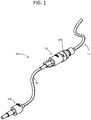
- FIG. 1 shows a preferred embodiment of a tubing system 10 including a distal assembly 12, a breakaway assembly 14, a proximal assembly 16, and an adapter assembly 18. As depicted, the assemblies are connected in succession to each other.
- the preferred distal assembly 12 preferably includes a distal tubing 20 and a first luer tip 22.
- the first luer tip 22 is friction fitted on one end of the distal tubing 20 as shown.
- the distal tubing 20 is connected to a fluid source (not shown).
- the fluid source is a container of an intravenous solution.
- the fluid source is an intracorporeal portion of a drain or tube. It will be understood by those skilled in the art that in other embodiments an infusion pump or other apparatus may be positioned between the distal assembly 12 and the fluid source.
- the breakaway assembly 14 includes a first breakaway subassembly 30 and a second breakaway subassembly 40.
- FIG. 3 depicts the first breakaway subassembly 30 including a first fluid passageway 32, a first bellows sheath 34, a first sheath channel 35, a first connector ring 36, a lock ring 38, and a lock post acceptor 146.
- the first fluid passageway 32 is configured to receive the first luer tip 22 such that fluid from the distal assembly 12 flows through the first luer tip 22 and into the first fluid passageway 32.
- the first fluid passageway 32 has a first pore 33 that is in communication with the first sheath channel 35.
- the first bellows sheath 34 is positioned within the first sheath channel 35.
- the first bellows sheath 34 is preferably made of an elastomeric substance.
- the elastomeric substance is preferably USP class VI liquid silicone rubber. It will be understood that the first bellows sheath is capable of being compressed into at least two different positions, a first position in which the first bellows sheath 34 seals the first pore 33 (as shown in FIG. 4 ) and a second position in which the first bellows sheath 34 permits fluid to pass through the first pore 33 (as shown in FIG. 5 ).
- the first connector ring 36 includes a plurality of finger flanges 37 (shown in FIG. 3 ). The first connector ring 36 is positioned around an exterior surface of the first breakaway subassembly 30.
- the second breakaway subassembly 40 includes a second fluid passageway 42, a second bellows sheath 44, a second sheath channel 45, a plurality of connector ring flange slots 46, a luer connection channel 47, a luer connector ring 48, a spring 51, a luer release button 52, an interior plate 53 and a lock post 145.
- the second bellows sheath 44 is positioned within the second sheath channel 45.
- the second bellows sheath 44 is preferably made of an elastomeric substance.
- the elastomeric substance is preferably USP class VI liquid silicone rubber.
- the luer connection channel 47 is positioned within the second breakaway subassembly 40 and is separated from the second sheath channel 45 by the interior plate 53.
- the luer connection channel 47 is configured to receive the spring 51 and the luer connector ring 48.
- the spring 51 is positioned within the luer connection channel 47 and abuts the interior plate 53.
- the luer connector ring 48 includes a release tab 49 and a plurality of luer connection flanges 50, and is positioned within the luer connection channel 47, pressing against the spring 51. It will be understood that as the luer connector ring 48 is pressed within the luer connection channel 47, the spring 51 is compressed against the interior plate 53.
- the luer connector ring 48 can be pressed into the luer connection channel 47 such that the release tab 49 engages a complementary geometric protrusion of the luer release button 52, as shown in FIGS. 4 and 5 . It will be further understood that when the release tab 49 engages the luer release button 52, the luer connector ring 38 is secured within the luer connection channel 47 despite the force exerted by the spring 51 against the luer connector ring 38.
- the second fluid passageway extends through the second breakaway subassembly 40 such that fluid from the distal assembly 12 can flow through the first breakaway subassembly 30, into the second pore 43, and out to the proximal assembly 16.
- the second fluid passageway 42 has a second pore 43 that is in communication with the second sheath channel 45.
- the second bellows sheath 44 is capable of being compressed into at least two different positions, a first position in which the second bellows sheath 44 seals the second pore 43 (as shown in FIG. 4 ) and a second position in which the second bellows sheath 44 permits fluid to pass through the second pore 43 (as shown in FIG. 5 ).
- the first breakaway subassembly 30 and the second breakaway subassembly 40 may be connected by aligning the first bellows sheath 34 with second bellows sheath 44 and pressing the two breakaway subassemblies together such that the finger flanges 37 of the first connector ring 36 engage the connector ring flange slots 46 that are positioned around the exterior of the second breakaway subassembly 40, as shown in FIG. 5 . It will be understood that when the two breakaway subassemblies 30, 40 are connected in this manner, the first bellow sheath 34 is compressed into the first sheath channel 35 in a manner that unseals the first pore 33.
- the breakaway subassemblies 30, 40 are connected in this manner, a fluid path 100 is created that permits fluid to flow from the first fluid passageway 32 through the fluid path 100 and into the second fluid passageway 42, as shown in FIG. 5 .
- the breakaway subassemblies 30, 40 may have more than one first pore 33 and may have more than one second pore 43, as shown in FIG. 5 .
- the first breakaway subassembly 30 and second breakaway subassembly 40 may be disconnected when a sufficient force, which may be between 5 and 7 pounds of tension force, is applied to dislodge the finger flanges 37 of the first connector ring 36 from the connector ring flange slots 46.
- a sufficient force which may be between 5 and 7 pounds of tension force
- the first pore 33 is sealed off as the first bellows sheath 34 expands within the first sheath channel 35.
- the second pore 43 is sealed off as the second bellows sheath 44 expands within the second sheath channel 45. It will be understood that this creates a self-sealing system, such that if an accidental disconnection occurs, the breakaway assembly 14 will seal the fluid path 100 in such a way that no fluid escapes the tubing system 10.
- the lock ring 38 of the first breakaway subassembly 30 can be adjusted circumferentially to engage or disengage the lock post 145 of the second breakaway subassembly 40 by way of the lock post acceptor 146 to achieve two states: a first state in which the breakaway subassemblies 30, 40 cannot be separated, and a second state that permits disconnection upon application of a sufficient force, which may be between 5 and 7 pounds of tension force. It will be further understood that to promote judicious infection control, reconnection of the subassemblies 30, 40 is discouraged.
- the breakaway assembly 14 is delivered to the user in a connected state.
- the finger flanges 37 of the first breakaway subassembly 30 are configured to flex inward towards the central radius of the first breakaway subassembly 30 such that they can no longer clear the diameter of the second breakaway subassembly 40 to engage the connector ring flange slots 46. This preferred mechanism prevents the breakaway subassemblies 30, 40 from being reconnected after they are initial disconnected.
- the preferred proximal assembly 16 includes a second luer tip 60 and a proximal tubing 61.
- the proximal tubing 61 is flush fitted within the second luer tip 60.
- the second luer tip 60 engages the plurality of luer connection flanges 50 which secure the second luer tip 60 to the second breakaway subassembly 40 when the luer connector ring 48 is second within the luer connection channel 47.
- FIG. 6 depicts the adapter assembly 18, which preferably includes a luer connector assembly 80, which engages a standard luer tip 90.
- the luer connector assembly 80 includes an interior plate 81, a third fluid passageway 82, a luer connector ring 84, a luer connection channel 87, a luer release button 88, and a spring outside the fluid path 89.
- the luer connection channel 87 is configured to receive the spring 89 and the luer connector ring 84.
- the spring 89 is positioned within the luer connection channel 87 and abuts the interior plate 81.
- the luer connector ring 84 includes a release tab 85 and a plurality of luer connection fingers 86, and is positioned within the luer connection channel 87, pressing against the spring 89. It will be understood that as the luer connector ring 84 is pressed within the luer connection channel 87, the spring 89 is compressed against the interior plate 81.
- the luer connector ring 84 can be pressed into the luer connection channel 87 such that the release tab 85 engages the luer release button 88, as shown in FIG. 9 . It will be further understood that when the release tab 85 engages the luer release button 88, the luer connector ring 84 is secured within the luer connection channel 87 despite the force exerted by the spring 89 against the luer connector ring 84.
- the third fluid passageway 82 extends through the luer connector assembly 80 such that fluid from the proximal assembly 16 flows through the luer connector assembly 80.
- FIGS. 8 and 9 show the luer tip 90, which includes a connection flange 91.
- the luer tip 90 is standard luer tip used in typical catheter assemblies known in the art. It will be understood that as a standard luer tip 90 engages the luer connector assembly 80, the plurality of luer connection fingers 86 engage the connection flange 91, and that as the luer tip 90 and luer connector ring 84 are pressed further into the channel, the luer connection fingers 86 are forced down behind the connection flange 91. In this manner a luer tip 90 is secured to the luer connector assembly 80.
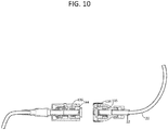
- FIGS. 10 and 11 depict such an alternative embodiment, wherein the elastomeric first and second bellows sheaths are replaced with pusher plates 134, 144 and springs 135, 136.
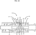
- FIG. 13 Yet another alternative embodiment of a breakaway assembly 214 is shown in FIG. 13 , which includes a first breakaway subassembly 230 and a second breakaway subassembly 240.
- the first breakaway subassembly 230 includes a first fluid passageway 232, a first bellows sheath 234, and a first sheath channel 235.
- the first fluid passageway 232 has a first pore 233 that is in communication with the first sheath channel 235.
- the first bellows sheath 234 is positioned within the first sheath channel 235.
- the first bellows sheath 234 is preferably made of an elastomeric substance.
- the elastomeric substance is preferably USP class VI liquid silicone rubber.
- first bellows sheath is capable of being compressed into at least two different positions, a first position in which the first bellows sheath 234 seals the first pore 233 (as shown in FIGS. 4 and 24 ) and a second position in which the first bellows sheath 234 permits fluid to pass through the first pore 233 (as shown in FIGS. 5 , 13 and 25 ).
- the first breakaway subassembly 230 also includes flanges 237 for securing the first breakaway subassembly 230 to the second breakaway subassembly 240.
- the second breakaway subassembly 240 includes a second fluid passageway 242, a second bellows sheath 244, a second sheath channel 245, a plurality of connector ring flange slots 246, a luer connection 247.
- the second bellows sheath 244 is positioned within the second sheath channel 245.
- the second bellows sheath 244 is preferably made of an elastomeric substance.
- the elastomeric substance is preferably USP class VI liquid silicone rubber.
- the second fluid passageway 242 extends through the second breakaway subassembly 240 such that fluid can flow through the first breakaway subassembly 230, into the second pore 243, and out to the second fluid passageway 242.
- the second fluid passageway 242 has a second pore 243 that is in communication with the second sheath channel 245.
- the second bellows sheath 244 is capable of being compressed into at least two different positions, a first position in which the second bellows sheath 244 seals the second pore 243 (as shown in FIGS. 4 and 24 ) and a second position in which the second bellows sheath 244 permits fluid to pass through the second pore 243 and into the second fluid passageway 242 (as shown in FIGS. 5 , 13 and 25 ).
- the breakaway assemblies 230, 240 may include more than one first pore 233 and may include more than one second pore 243, as shown in FIG. 13 .
- the second breakaway subassembly 240 includes a luer connection 247 that is in communication with the second fluid passageway 242 and is configured to accept a connection with typical luer locks 300 used in the field and known to those skilled to those in the art.
- the first breakaway subassembly 230 and the second breakaway subassembly 240 may be connected by aligning the first bellows sheath 234 with second bellows sheath 244 and pressing the two breakaway subassemblies together such that the finger flanges 237 engage flange slots 246 that are positioned around the exterior of the second breakaway subassembly 240, as shown in FIG. 13 . It will be understood that when the two breakaway subassemblies 230, 240 are connected in this manner, the first bellow sheath 234 is compressed into the first sheath channel 235 in a manner that unseals the first pore 233.
- the second bellows sheath 244 is compressed in the second sheath channel 245 thereby unsealing the second pore 243.
- a fluid path 200 is created that permits fluid to flow from the first fluid passageway 232 through the fluid path 200 and into the second fluid passageway 242, as shown in FIG. 13 . It should be noted that flow of the fluid path 200 is not obstructed by the operation of the bellows sheaths 234, 244 because the bellows sheaths are outside of the flow path of the fluids.
- the first breakaway subassembly 230 and second breakaway subassembly 240 may be disconnected when a sufficient force, which may be between 5 and 7 pounds of tension force, is applied to dislodge the finger flanges 237 from the flange slots 246.
- a sufficient force which may be between 5 and 7 pounds of tension force
- the first pore 233 is sealed off as the first bellows sheath 234 expands within the first sheath channel 235.
- the second pore 243 is sealed off as the second bellows sheath 44 expands within the second sheath channel 245. It will be understood that this creates a self-sealing system, such that if an accidental disconnection occurs, the breakaway assembly 214 will seal the fluid path in such a way that no fluid escapes the tubing system 10.
- the first breakaway subassembly 230 and the second breakaway subassembly 240 may also be locked into place.
- the first breakaway subassembly 230 also includes a locking tab 220.
- the locking tab 220 is configured to be inserted into a locking slot 210 on the second breakaway subassembly 240, shown in FIG. 15 .
- the locking slot 210 is configured so that when the locking tab 220 is inserted into the locking slot 210 and the first breakaway subassembly 230 is rotated relative to the section breakaway subassembly 240, the first breakaway subassembly 230 and the second breakaway subassembly are locked together.
- first breakaway subassembly 230 While locking the first breakaway subassembly 230 to the second breakaway subassembly 240 is possible, it is not necessary for the invention to perform its purpose as described above. It will be understood that the invention can be engaged in two separate states: a first state where the first breakaway subassembly 230 cannot be disconnected from the second breakaway subassembly 240 because the locking tab 220 is engaged and rotated into the locking slot 210; and a second state where sufficient force (which may be between 5 and 7 lbs. of tension force) allows disconnection of the first breakaway subassembly 230 and the second breakaway subassembly 240.
- sufficient force which may be between 5 and 7 lbs. of tension force
- the first breakaway subassembly 230 and the second breakaway subassembly 240 must be rotated in opposite directions to unlock the device before the finger flanges 237 can be dislodges from the flange slots 246.
- the second breakaway subassembly 240 is further shown in a disconnected state in FIGS. 14 , 15 , and 16 .
- the second breakaway assembly 240 of Figs. 14 and 16 include flange slots 246, the locking slot 210, and a second luer tip connection 260.
- FIG. 15 shows a second breakaway assembly 240 that includes second bellows sheath channel 245, second pore 243, and second fluid passageway 242.
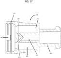
- the first breakaway subassembly 230 is further shown in a disconnected state in FIGS. 17 and 18 .
- the first breakaway assembly 230 of FIG. 17 includes finger flanges 237, a locking tab 220, a first fluid passageway 232, first bellows sheath channel 235, a first luer connection 222, and pore 233.
- the first breakaway assembly 230 of FIG. 18 includes finger flanges 237, locking mechanisms 220, and a first luer connection 222.
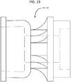
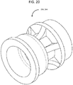
- FIGS. 19 , 20 , and 21 show the bellows sheaths 234, 244 in the state when the first breakaway subassembly 230 and the second breakaway subassembly 240 are disconnected, as in FIGS. 14-18 .
- the bellows sheaths 234, 244 compress, resulting in the opening of the pores 233, 243 (shown in FIG. 13 ). Once the pores 233, 243 open, the fluid may flow through the subassemblies 230, 240.
- all components are made of non-metallic substances, such as plastic and elastomeric substances, which is beneficial for imaging and other procedures in the medical field that prohibit the use of metallic substances during those procedures.
- FIG. 22 An alternative embodiment of a tubing system 400 for use with the first breakaway subassembly 230 and the second breakaway subassembly 240, as illustrated in FIGS. 13-21 and detailed above, is shown in FIG. 22 .
- the tubing system 400 includes a first luer connection assembly 410, a second luer connection assembly 420, a proximal tubing 416, second luer tip 480, a first luer tip 482, and a distal tubing 412.
- the first luer connection assembly 410 connects to the first breakaway subassembly 230
- the second luer connection assembly 420 connects to the second breakaway subassembly 240.
- first and second breakaway assemblies 230, 240 are the preferred embodiment for the connection of the first and second luer connection assemblies 410, 420, it will be understood that other breakaway assemblies disclosed herein can be modified for use with the first and second luer connection assemblies 410, 420.
- the first breakaway subassembly 230 includes a first fluid passageway 232, a first bellows sheath 234, a notch 450, and a first sheath channel 235.
- the first fluid passageway 232 has a first pore 233 that is in communication with the first sheath channel 235.
- the first bellows sheath 234 is positioned within the first sheath channel 235.
- the first bellows sheath 234 is preferably made of an elastomeric substance.
- the elastomeric substance is preferably USP class VI liquid silicone rubber.
- first bellows sheath is capable of being compressed into at least two different positions, a first position in which the first bellows sheath 234 seals the first pore 233 (as shown in Fig. 24 ) and a second position in which the first bellows sheath 234 permits fluid to pass through the first pore 233 (as shown in FIG. 25 ).
- the first breakaway subassembly 230 also includes flanges 237 for securing the first breakaway subassembly 230 to the second breakaway subassembly 240.
- the second breakaway subassembly 240 includes a second fluid passageway 242, a second bellows sheath 244, a second sheath channel 245, a plurality of connector ring flange slots 246, a notch, and a luer connection channel 247.
- the second bellows sheath 244 is positioned within the second sheath channel 245.
- the second bellows sheath 244 is preferably made of an elastomeric substance.
- the elastomeric substance is preferably USP class VI liquid silicone rubber.
- the second fluid passageway 242 extends through the second breakaway subassembly 240 such that fluid can flow through the first breakaway subassembly 230, into the second pore 243, and out to the second fluid passageway 242.
- the second fluid passageway 242 has a second pore 243 that is in communication with the second sheath channel 245.
- the second bellows sheath 244 is capable of being compressed into at least two different positions, a first position in which the second bellows sheath 244 seals the second pore 243 (as shown in FIG. 24 ) and a second position in which the second bellows sheath 244 permits fluid to pass through the second pore 243 and into the second fluid passageway 242 (as shown in FIG. 25 ).
- the operation and connection of the breakaway subassemblies 230, 240 are explained in more detail above.
- the preferred first luer connection assembly 410 includes a flange 452, threads 470, and a luer connection channel 430.
- the second luer connection assembly 420 includes a flange 452, threads 470, and a luer connection channel 430.
- the flange 452 of the first luer connection assembly 410 slides into the flange acceptor 454 of the first luer tip 482 with sufficient force, securely connecting the first luer connection assembly 410 to the first luer tip 482.
- the threads 470 of the first luer connection assembly 410 connect to the tab 490 of the first breakaway subassembly 230, securely connecting the first luer connection assembly 410 to the first breakaway subassembly 230.
- the distal tubing 416 is friction fitted to the first luer tip 482. It will be understood that these components of the invention may be connected in any order.
- the flange 452 of the second luer connection assembly 420 slides into the notch 450 of the second breakaway subassembly 240 with sufficient force, securely connecting the second luer connection assembly 420 to the second breakaway subassembly 240.
- the second luer tip 480 is connected to the threads 470 of the second luer connection assembly 420, securely attaching the second luer tip 480 to the second luer connection assembly.
- the proximal tubing 416 is friction fitted to the second luer tip 480. It will be understood that these components of the invention may be connected in any order.
- the flanges 452 being connected to the notches 452 and the flange acceptors 454 allows for the quick disconnect and replacement of the components tubing system 400, which is very advantageous in the medical field.
- FIG. 25 shows the embodiment of FIG. 24 , but displays the connection of the first breakaway assembly 230 and the second breakaway assembly 240.
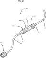
- FIG. 26 shows the embodiment of FIG. 25 , with the addition of a luer adaptor 518.
- FIG. 23 shows a first breakaway subassembly 230, a second breakaway subassembly 240, a first bellows sheath 234, a second bellows sheath 244, and a second luer connection assembly 420.
- the bellows sheaths 234, 244 have been removed from the first breakaway subassembly 230 and the second breakaway subassembly 240 in FIG. 23 for illustration purposes.
Landscapes
- Health & Medical Sciences (AREA)
- Heart & Thoracic Surgery (AREA)
- Pulmonology (AREA)
- Engineering & Computer Science (AREA)
- Anesthesiology (AREA)
- Biomedical Technology (AREA)
- Hematology (AREA)
- Life Sciences & Earth Sciences (AREA)
- Animal Behavior & Ethology (AREA)
- General Health & Medical Sciences (AREA)
- Public Health (AREA)
- Veterinary Medicine (AREA)
- Infusion, Injection, And Reservoir Apparatuses (AREA)
- Quick-Acting Or Multi-Walled Pipe Joints (AREA)
Description
- This application claims the benefit of a provisional application, Application No.
62/183,996, filed June 24, 2015 - The present invention is related to medical access devices, and more particularly to a a connect and disconnect system for medical tubing.
- Medical access devices, such as disclosed in
WO2011/029056 A2 , are used in the treatment of hospitalized patients for a variety of purposes, including intravenous catheters, feeding tubes, Foley catheters, chest tubes, and a variety of surgical drains. Many of these medical access devices transport fluids from or to the patient and use a variety of flexible tubes to give the patient a range of movement during treatment. Unfortunately, due to the freedom of movement that some patients exhibit, the tubing associated with medical access devices is often subjected to forces that cause damage to the tubing, the patient, or both. For example, the tubing typically used in the administration of intravenous fluids is often several feet long, and accordingly can become entangled on hospital beds or other medical equipment surrounding the patient. As the patient moves, the tubing can be stretched. In extreme cases (which occur with astonishing frequency), the fluids being administered to the patient, or the patient's own body fluids can be spilled, creating a risk of contamination to the patient's treatment environment, and potentially exposing the patient to a risk of infection. - Thus there is a need for a system that prevents such damage caused by such forces. There is a further need for such a system that can be used with the variety of existing medical devices, without alteration to such medical devices. Such a system is described below.
- The invention is defined in the independent claims 1 and 8. A tubing system includes a distal tubing assembly, a breakaway assembly, a proximal tubing assembly, and an adapter assembly. The distal tubing assembly includes a distal tubing connected to a fluid source and a first luer tip. The luer tip is inserted into the breakaway assembly, which includes a first breakaway subassembly and a second breakaway subassembly. The first breakaway subassembly includes a first fluid passageway that engages the luer tip of the distal tubing assembly, and an elastomeric first bellows sheath positioned within a first sheath channel. The second breakaway subassembly includes a second fluid passageway, a second bellows sheath positioned within a second sheath channel, a luer connector ring positioned within a luer connector channel. The first breakaway subassembly and second breakaway subassembly are initially connected with their respective sheaths aligned. A lock selectively engages to prevent disconnection of the breakaway subassemblies. The proximal tubing assembly includes a proximal tubing connected to a second luer tip, which in turn engages the luer connector ring of the second breakaway subassembly. The adapter assembly engages the proximal tubing assembly via its third fluid passageway. The adapter assembly also includes a luer tip with a flange that can engage and secure a standard luer connection.
- An alternative embodiment of a breakaway assembly includes a first breakaway subassembly and a second breakaway subassembly. The first breakaway subassembly includes a first fluid passageway, a first bellows sheath, and a first sheath channel. The first fluid passageway has a first pore that is in communication with the first sheath channel. The first bellows sheath is positioned within the first sheath channel. The first bellows sheath is preferably made of an elastomeric substance. It will be understood that the first bellows sheath is capable of being compressed into at least two different positions, a first position in which the first bellows sheath seals the first pore and a second position in which the first bellows sheath permits fluid to pass through the first pore. The first breakaway subassembly also includes flanges for securing the first breakaway subassembly to the second breakaway subassembly. The second breakaway subassembly includes a second fluid passageway, a second bellows sheath, a second sheath channel, a plurality of connector ring flange slots, a luer connection. The second bellows sheath is positioned within the second sheath channel. The second bellows sheath is preferably made of an elastomeric substance. The elastomeric substance is preferably USP class VI liquid silicone rubber. The second fluid passageway extends through the second breakaway subassembly such that fluid can flow through the first breakaway subassembly, into the second pore, and out to the second fluid passageway. Specifically, the second fluid passageway has a second pore that is in communication with the second sheath channel. The second bellows sheath is capable of being compressed into at least two different positions, a first position in which the second bellows sheath seals the second pore and a second position in which the second bellows sheath permits fluid to pass through the second pore and into the second fluid passageway.
- An alternative embodiment of a tubing system for use with the first breakaway subassembly and the second breakaway subassembly in the alternative breakaway assembly includes a first luer connection assembly, a second luer connection assembly, a proximal tubing, second luer tip, a first luer tip, and a distal tubing. The first luer connection assembly connects to the first breakaway subassembly, and the second luer connection assembly connects to the second breakaway subassembly. While the first and second breakaway assemblies are the preferred embodiment for the connection of the first and second luer connection assemblies, it will be understood that other breakaway assemblies disclosed herein can be modified for use with the first and second luer connection assemblies. The preferred first luer connection assembly includes a flange, threads, and a luer connection channel. Similarly, the second luer connection assembly includes a flange, threads, and a luer connection channel. The flange of the first luer connection assembly slides into the flange acceptor of the first luer tip with sufficient force, securely connecting the first luer connection assembly to the first luer tip. The threads of the first luer connection assembly connect to the tab of the first breakaway subassembly, securely connecting the first luer connection assembly to the first breakaway subassembly. The distal tubing is friction fitted to the first luer tip. It will be understood that these components of the invention may be connected in any order. The flange of the second luer connection assembly slides into the notch of the second breakaway subassembly with sufficient force, securely connecting the second luer connection assembly to the second breakaway subassembly. The second luer tip is connected to the threads of the second luer connection assembly, securely attaching the second luer tip to the second luer connection assembly. The proximal tubing is friction fitted to the second luer tip. It will be understood that these components of the invention may be connected in any order. The flanges being connected to the notch and the flange acceptor allows for the quick disconnect and replacement of the components tubing system, which is very advantageous in the medical field.
-
-
Figure 1 - A perspective view of a preferred tubing system. -
Figure 2 - A perspective view of a preferred breakaway assembly in its disconnected state. -
Figure 3 - An exploded side view of a preferred breakaway assembly, with internal structure depicted with dashed lines. -
Figure 4 - A side cross-sectional view of a distal assembly, a preferred breakaway assembly in its disconnected state and a proximal assembly. -
Figure 5 - A side cross-sectional view of a distal assembly, a preferred breakaway assembly in its connected state, and a proximal assembly. -
Figure 6 - A perspective view of a preferred adapter assembly in its disconnected state. -
Figure 7 - An exploded side view of a preferred adapter assembly. -
Figure 8 - A side cross-sectional view of a preferred adapter assembly in its disconnected state. -
Figure 9 - A side cross-sectional view of a preferred adapter assembly in its connected state. -
Figure 10 - A side cross-sectional view of an alternative embodiment of the breakaway assembly in its disconnected state. -
Figure 11 - A side cross-sectional view of an alternative embodiment of the breakaway assembly in its connected state. -
Figure 12 - An exploded side view of an alternative embodiment of the breakaway assembly, with internal structure depicted with dashed lines. -
Figure 13 - A side cross-sectional view of an alternative embodiment of the breakaway assembly in its connected state. -
Figure 14 - A side view of an alternative embodiment of the second breakaway assembly. -
Figure 15 - A side, cross-sectional view of an alternative embodiment of the second breakaway assembly. -
Figure 16 - A perspective view of the of an alternative embodiment second breakaway assembly. -
Figure 17 - A side view of the of an alternative embodiment first breakaway assembly, with internal structure depicted with dashed lines. -
Figure 18 - A perspective view of the of an alternative embodiment first breakaway assembly. -
Figure 19 - A side view of a bellows sheath with internal structure depicted with dashed lines. -
Figure 20 - A perspective view of a bellows sheath. -
Figure 21 - A partial cross-section view of a bellows sheath. -
Figure 22 - A perspective view of an alternative embodiment of a tubing system, disconnected. -
Figure 23 - A side view of an alternative embodiment of a second luer connection assembly, with a first breakaway assembly, a second breakaway assembly, and bellowssheaths FIGS. 13-21 , with internal structure depicted with dashed lines. -
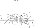
Figure 24 - A side cross sectional view of the alternative embodiment of a tubing system, with the first breakaway assembly and second breakaway assembly disconnected. -
Figure 25 - A side cross sectional view of the alternative embodiment of a tubing system, with the first breakaway assembly and second breakaway assembly connected. -
Figure 26 - A perspective view of the alternative embodiment of a tubing system, connected. -
FIG. 1 shows a preferred embodiment of a tubing system 10 including adistal assembly 12, abreakaway assembly 14, aproximal assembly 16, and anadapter assembly 18. As depicted, the assemblies are connected in succession to each other. - Turning to
FIG. 4 , the preferreddistal assembly 12 preferably includes adistal tubing 20 and afirst luer tip 22. Thefirst luer tip 22 is friction fitted on one end of thedistal tubing 20 as shown. Thedistal tubing 20 is connected to a fluid source (not shown). In the preferred embodiment, the fluid source is a container of an intravenous solution. In alternative embodiments the fluid source is an intracorporeal portion of a drain or tube. It will be understood by those skilled in the art that in other embodiments an infusion pump or other apparatus may be positioned between thedistal assembly 12 and the fluid source. - Turning to
FIGS. 2-5 , thebreakaway assembly 14 includes afirst breakaway subassembly 30 and asecond breakaway subassembly 40.FIG. 3 depicts thefirst breakaway subassembly 30 including afirst fluid passageway 32, a first bellowssheath 34, afirst sheath channel 35, a first connector ring 36, alock ring 38, and alock post acceptor 146. In the depicted embodiment, thefirst fluid passageway 32 is configured to receive thefirst luer tip 22 such that fluid from thedistal assembly 12 flows through thefirst luer tip 22 and into thefirst fluid passageway 32. Thefirst fluid passageway 32 has afirst pore 33 that is in communication with thefirst sheath channel 35. The first bellowssheath 34 is positioned within thefirst sheath channel 35. The first bellowssheath 34 is preferably made of an elastomeric substance. The elastomeric substance is preferably USP class VI liquid silicone rubber. It will be understood that the first bellows sheath is capable of being compressed into at least two different positions, a first position in which thefirst bellows sheath 34 seals the first pore 33 (as shown inFIG. 4 ) and a second position in which thefirst bellows sheath 34 permits fluid to pass through the first pore 33 (as shown inFIG. 5 ). In the depicted embodiment, the first connector ring 36 includes a plurality of finger flanges 37 (shown inFIG. 3 ). The first connector ring 36 is positioned around an exterior surface of thefirst breakaway subassembly 30. - Turning back to
FIG. 3 , thesecond breakaway subassembly 40 includes a second fluid passageway 42, a second bellowssheath 44, asecond sheath channel 45, a plurality of connectorring flange slots 46, aluer connection channel 47, aluer connector ring 48, a spring 51, aluer release button 52, aninterior plate 53 and alock post 145. The second bellowssheath 44 is positioned within thesecond sheath channel 45. The second bellowssheath 44 is preferably made of an elastomeric substance. The elastomeric substance is preferably USP class VI liquid silicone rubber. Theluer connection channel 47 is positioned within thesecond breakaway subassembly 40 and is separated from thesecond sheath channel 45 by theinterior plate 53. Theluer connection channel 47 is configured to receive the spring 51 and theluer connector ring 48. The spring 51 is positioned within theluer connection channel 47 and abuts theinterior plate 53. Theluer connector ring 48 includes a release tab 49 and a plurality ofluer connection flanges 50, and is positioned within theluer connection channel 47, pressing against the spring 51. It will be understood that as theluer connector ring 48 is pressed within theluer connection channel 47, the spring 51 is compressed against theinterior plate 53. With sufficient force, theluer connector ring 48 can be pressed into theluer connection channel 47 such that the release tab 49 engages a complementary geometric protrusion of theluer release button 52, as shown inFIGS. 4 and5 . It will be further understood that when the release tab 49 engages theluer release button 52, theluer connector ring 38 is secured within theluer connection channel 47 despite the force exerted by the spring 51 against theluer connector ring 38. The second fluid passageway extends through thesecond breakaway subassembly 40 such that fluid from thedistal assembly 12 can flow through thefirst breakaway subassembly 30, into thesecond pore 43, and out to theproximal assembly 16. Specifically, the second fluid passageway 42 has asecond pore 43 that is in communication with thesecond sheath channel 45. The second bellowssheath 44 is capable of being compressed into at least two different positions, a first position in which thesecond bellows sheath 44 seals the second pore 43 (as shown inFIG. 4 ) and a second position in which thesecond bellows sheath 44 permits fluid to pass through the second pore 43 (as shown inFIG. 5 ). - The
first breakaway subassembly 30 and thesecond breakaway subassembly 40 may be connected by aligning thefirst bellows sheath 34 withsecond bellows sheath 44 and pressing the two breakaway subassemblies together such that thefinger flanges 37 of the first connector ring 36 engage the connectorring flange slots 46 that are positioned around the exterior of thesecond breakaway subassembly 40, as shown inFIG. 5 . It will be understood that when the twobreakaway subassemblies first bellow sheath 34 is compressed into thefirst sheath channel 35 in a manner that unseals thefirst pore 33. Similarly, thesecond bellows sheath 44 is compressed in thesecond sheath channel 45 thereby unsealing thesecond pore 43. When the twobreakaway subassemblies fluid path 100 is created that permits fluid to flow from thefirst fluid passageway 32 through thefluid path 100 and into the second fluid passageway 42, as shown inFIG. 5 . It will be understood that thebreakaway subassemblies 30, 40 (and other embodiments disclosed herein) may have more than onefirst pore 33 and may have more than onesecond pore 43, as shown inFIG. 5 . - In this first preferred embodiment, the
first breakaway subassembly 30 andsecond breakaway subassembly 40 may be disconnected when a sufficient force, which may be between 5 and 7 pounds of tension force, is applied to dislodge thefinger flanges 37 of the first connector ring 36 from the connectorring flange slots 46. When the twobreakaway subassemblies first pore 33 is sealed off as thefirst bellows sheath 34 expands within thefirst sheath channel 35. Similarly, thesecond pore 43 is sealed off as thesecond bellows sheath 44 expands within thesecond sheath channel 45. It will be understood that this creates a self-sealing system, such that if an accidental disconnection occurs, thebreakaway assembly 14 will seal thefluid path 100 in such a way that no fluid escapes the tubing system 10. - It will be understood that the
lock ring 38 of thefirst breakaway subassembly 30 can be adjusted circumferentially to engage or disengage thelock post 145 of thesecond breakaway subassembly 40 by way of thelock post acceptor 146 to achieve two states: a first state in which thebreakaway subassemblies subassemblies breakaway assembly 14 is delivered to the user in a connected state. In the event a force is applied to disconnect the twobreakaway subassemblies finger flanges 37 of thefirst breakaway subassembly 30 are configured to flex inward towards the central radius of thefirst breakaway subassembly 30 such that they can no longer clear the diameter of thesecond breakaway subassembly 40 to engage the connectorring flange slots 46. This preferred mechanism prevents thebreakaway subassemblies - The preferred
proximal assembly 16 includes asecond luer tip 60 and aproximal tubing 61. Theproximal tubing 61 is flush fitted within thesecond luer tip 60. Thesecond luer tip 60 engages the plurality ofluer connection flanges 50 which secure thesecond luer tip 60 to thesecond breakaway subassembly 40 when theluer connector ring 48 is second within theluer connection channel 47. -
FIG. 6 depicts theadapter assembly 18, which preferably includes aluer connector assembly 80, which engages astandard luer tip 90. Turning toFIG. 7 , theluer connector assembly 80 includes aninterior plate 81, athird fluid passageway 82, aluer connector ring 84, a luer connection channel 87, aluer release button 88, and a spring outside thefluid path 89. - The luer connection channel 87 is configured to receive the
spring 89 and theluer connector ring 84. Thespring 89 is positioned within the luer connection channel 87 and abuts theinterior plate 81. Theluer connector ring 84 includes arelease tab 85 and a plurality ofluer connection fingers 86, and is positioned within the luer connection channel 87, pressing against thespring 89. It will be understood that as theluer connector ring 84 is pressed within the luer connection channel 87, thespring 89 is compressed against theinterior plate 81. With sufficient force, theluer connector ring 84 can be pressed into the luer connection channel 87 such that therelease tab 85 engages theluer release button 88, as shown inFIG. 9 . It will be further understood that when therelease tab 85 engages theluer release button 88, theluer connector ring 84 is secured within the luer connection channel 87 despite the force exerted by thespring 89 against theluer connector ring 84. Thethird fluid passageway 82 extends through theluer connector assembly 80 such that fluid from theproximal assembly 16 flows through theluer connector assembly 80. -
FIGS. 8 and9 show theluer tip 90, which includes aconnection flange 91. Those skilled in the art will recognize that theluer tip 90 is standard luer tip used in typical catheter assemblies known in the art. It will be understood that as astandard luer tip 90 engages theluer connector assembly 80, the plurality ofluer connection fingers 86 engage theconnection flange 91, and that as theluer tip 90 andluer connector ring 84 are pressed further into the channel, theluer connection fingers 86 are forced down behind theconnection flange 91. In this manner aluer tip 90 is secured to theluer connector assembly 80. - Other alternative embodiments, not according to the invention, of each aspect of the disclosed tubing system 10 are possible. For example
FIGS. 10 and11 depict such an alternative embodiment, wherein the elastomeric first and second bellows sheaths are replaced withpusher plates - Yet another alternative embodiment of a
breakaway assembly 214 is shown inFIG. 13 , which includes afirst breakaway subassembly 230 and asecond breakaway subassembly 240. Thefirst breakaway subassembly 230 includes afirst fluid passageway 232, a first bellowssheath 234, and afirst sheath channel 235. Thefirst fluid passageway 232 has afirst pore 233 that is in communication with thefirst sheath channel 235. The first bellowssheath 234 is positioned within thefirst sheath channel 235. The first bellowssheath 234 is preferably made of an elastomeric substance. The elastomeric substance is preferably USP class VI liquid silicone rubber. It will be understood that the first bellows sheath is capable of being compressed into at least two different positions, a first position in which thefirst bellows sheath 234 seals the first pore 233 (as shown inFIGS. 4 and24 ) and a second position in which thefirst bellows sheath 234 permits fluid to pass through the first pore 233 (as shown inFIGS. 5 ,13 and25 ). Thefirst breakaway subassembly 230 also includesflanges 237 for securing thefirst breakaway subassembly 230 to thesecond breakaway subassembly 240. - The
second breakaway subassembly 240 includes asecond fluid passageway 242, a second bellowssheath 244, asecond sheath channel 245, a plurality of connectorring flange slots 246, aluer connection 247. The second bellowssheath 244 is positioned within thesecond sheath channel 245. The second bellowssheath 244 is preferably made of an elastomeric substance. The elastomeric substance is preferably USP class VI liquid silicone rubber. Thesecond fluid passageway 242 extends through thesecond breakaway subassembly 240 such that fluid can flow through thefirst breakaway subassembly 230, into thesecond pore 243, and out to thesecond fluid passageway 242. Specifically, thesecond fluid passageway 242 has asecond pore 243 that is in communication with thesecond sheath channel 245. The second bellowssheath 244 is capable of being compressed into at least two different positions, a first position in which thesecond bellows sheath 244 seals the second pore 243 (as shown inFIGS. 4 and24 ) and a second position in which thesecond bellows sheath 244 permits fluid to pass through thesecond pore 243 and into the second fluid passageway 242 (as shown inFIGS. 5 ,13 and25 ). It will be understood that thebreakaway assemblies first pore 233 and may include more than onesecond pore 243, as shown inFIG. 13 . - In the alternative embodiment depicted in
FIGS. 13 - 21 , it will be understood that no proximal assembly 60 (as shown inFIGS. 2 and4-5 ) is needed as thesecond breakaway subassembly 240 includes aluer connection 247 that is in communication with thesecond fluid passageway 242 and is configured to accept a connection with typical luer locks 300 used in the field and known to those skilled to those in the art. - The
first breakaway subassembly 230 and thesecond breakaway subassembly 240 may be connected by aligning thefirst bellows sheath 234 withsecond bellows sheath 244 and pressing the two breakaway subassemblies together such that thefinger flanges 237 engageflange slots 246 that are positioned around the exterior of thesecond breakaway subassembly 240, as shown inFIG. 13 . It will be understood that when the twobreakaway subassemblies first bellow sheath 234 is compressed into thefirst sheath channel 235 in a manner that unseals thefirst pore 233. Similarly, thesecond bellows sheath 244 is compressed in thesecond sheath channel 245 thereby unsealing thesecond pore 243. When the twobreakaway subassemblies fluid path 200 is created that permits fluid to flow from thefirst fluid passageway 232 through thefluid path 200 and into thesecond fluid passageway 242, as shown inFIG. 13 . It should be noted that flow of thefluid path 200 is not obstructed by the operation of the bellows sheaths 234, 244 because the bellows sheaths are outside of the flow path of the fluids. - The
first breakaway subassembly 230 andsecond breakaway subassembly 240 may be disconnected when a sufficient force, which may be between 5 and 7 pounds of tension force, is applied to dislodge thefinger flanges 237 from theflange slots 246. When the twobreakaway subassemblies first pore 233 is sealed off as thefirst bellows sheath 234 expands within thefirst sheath channel 235. Similarly, thesecond pore 243 is sealed off as thesecond bellows sheath 44 expands within thesecond sheath channel 245. It will be understood that this creates a self-sealing system, such that if an accidental disconnection occurs, thebreakaway assembly 214 will seal the fluid path in such a way that no fluid escapes the tubing system 10. - The
first breakaway subassembly 230 and thesecond breakaway subassembly 240 may also be locked into place. As shown inFIG. 17 , thefirst breakaway subassembly 230 also includes alocking tab 220. Thelocking tab 220 is configured to be inserted into alocking slot 210 on thesecond breakaway subassembly 240, shown inFIG. 15 . Thelocking slot 210 is configured so that when thelocking tab 220 is inserted into thelocking slot 210 and thefirst breakaway subassembly 230 is rotated relative to thesection breakaway subassembly 240, thefirst breakaway subassembly 230 and the second breakaway subassembly are locked together. While locking thefirst breakaway subassembly 230 to thesecond breakaway subassembly 240 is possible, it is not necessary for the invention to perform its purpose as described above. It will be understood that the invention can be engaged in two separate states: a first state where thefirst breakaway subassembly 230 cannot be disconnected from thesecond breakaway subassembly 240 because thelocking tab 220 is engaged and rotated into thelocking slot 210; and a second state where sufficient force (which may be between 5 and 7 lbs. of tension force) allows disconnection of thefirst breakaway subassembly 230 and thesecond breakaway subassembly 240. It will be understood that in the first state, thefirst breakaway subassembly 230 and thesecond breakaway subassembly 240 must be rotated in opposite directions to unlock the device before thefinger flanges 237 can be dislodges from theflange slots 246. - The
second breakaway subassembly 240 is further shown in a disconnected state inFIGS. 14 ,15 , and16 . Thesecond breakaway assembly 240 ofFigs. 14 and16 includeflange slots 246, thelocking slot 210, and a secondluer tip connection 260.FIG. 15 shows asecond breakaway assembly 240 that includes second bellowssheath channel 245,second pore 243, and secondfluid passageway 242. - The
first breakaway subassembly 230 is further shown in a disconnected state inFIGS. 17 and18 . Thefirst breakaway assembly 230 ofFIG. 17 includesfinger flanges 237, alocking tab 220, afirst fluid passageway 232, first bellowssheath channel 235, afirst luer connection 222, and pore 233. Thefirst breakaway assembly 230 ofFIG. 18 includesfinger flanges 237, lockingmechanisms 220, and afirst luer connection 222. -
FIGS. 19 ,20 , and21 show the bellows sheaths 234, 244 in the state when thefirst breakaway subassembly 230 and thesecond breakaway subassembly 240 are disconnected, as inFIGS. 14-18 . When a force is applied to thefirst breakaway subassembly 230 and thesecond breakaway subassembly 240 during connection, the bellows sheaths 234, 244 compress, resulting in the opening of thepores 233, 243 (shown inFIG. 13 ). Once thepores subassemblies - Importantly, in the preferred and alternative embodiments of the
tubing system 10, 400, all components are made of non-metallic substances, such as plastic and elastomeric substances, which is beneficial for imaging and other procedures in the medical field that prohibit the use of metallic substances during those procedures. - An alternative embodiment of a
tubing system 400 for use with thefirst breakaway subassembly 230 and thesecond breakaway subassembly 240, as illustrated inFIGS. 13-21 and detailed above, is shown inFIG. 22 . Thetubing system 400 includes a firstluer connection assembly 410, a secondluer connection assembly 420, aproximal tubing 416,second luer tip 480, afirst luer tip 482, and adistal tubing 412. The firstluer connection assembly 410 connects to thefirst breakaway subassembly 230, and the secondluer connection assembly 420 connects to thesecond breakaway subassembly 240. While the first andsecond breakaway assemblies luer connection assemblies luer connection assemblies - Turning to
FIG. 24 , thefirst breakaway subassembly 230 includes afirst fluid passageway 232, a first bellowssheath 234, anotch 450, and afirst sheath channel 235. Thefirst fluid passageway 232 has afirst pore 233 that is in communication with thefirst sheath channel 235. The first bellowssheath 234 is positioned within thefirst sheath channel 235. The first bellowssheath 234 is preferably made of an elastomeric substance. The elastomeric substance is preferably USP class VI liquid silicone rubber. It will be understood that the first bellows sheath is capable of being compressed into at least two different positions, a first position in which thefirst bellows sheath 234 seals the first pore 233 (as shown inFig. 24 ) and a second position in which thefirst bellows sheath 234 permits fluid to pass through the first pore 233 (as shown inFIG. 25 ). Thefirst breakaway subassembly 230 also includesflanges 237 for securing thefirst breakaway subassembly 230 to thesecond breakaway subassembly 240. - The
second breakaway subassembly 240 includes asecond fluid passageway 242, a second bellowssheath 244, asecond sheath channel 245, a plurality of connectorring flange slots 246, a notch, and aluer connection channel 247. The second bellowssheath 244 is positioned within thesecond sheath channel 245. The second bellowssheath 244 is preferably made of an elastomeric substance. The elastomeric substance is preferably USP class VI liquid silicone rubber. Thesecond fluid passageway 242 extends through thesecond breakaway subassembly 240 such that fluid can flow through thefirst breakaway subassembly 230, into thesecond pore 243, and out to thesecond fluid passageway 242. Specifically, thesecond fluid passageway 242 has asecond pore 243 that is in communication with thesecond sheath channel 245. The second bellowssheath 244 is capable of being compressed into at least two different positions, a first position in which thesecond bellows sheath 244 seals the second pore 243 (as shown inFIG. 24 ) and a second position in which thesecond bellows sheath 244 permits fluid to pass through thesecond pore 243 and into the second fluid passageway 242 (as shown inFIG. 25 ). The operation and connection of thebreakaway subassemblies - The preferred first
luer connection assembly 410 includes aflange 452,threads 470, and aluer connection channel 430. Similarly, the secondluer connection assembly 420 includes aflange 452,threads 470, and aluer connection channel 430. - The
flange 452 of the firstluer connection assembly 410 slides into theflange acceptor 454 of thefirst luer tip 482 with sufficient force, securely connecting the firstluer connection assembly 410 to thefirst luer tip 482. Thethreads 470 of the firstluer connection assembly 410 connect to thetab 490 of thefirst breakaway subassembly 230, securely connecting the firstluer connection assembly 410 to thefirst breakaway subassembly 230. Thedistal tubing 416 is friction fitted to thefirst luer tip 482. It will be understood that these components of the invention may be connected in any order. - The
flange 452 of the secondluer connection assembly 420 slides into thenotch 450 of thesecond breakaway subassembly 240 with sufficient force, securely connecting the secondluer connection assembly 420 to thesecond breakaway subassembly 240. Thesecond luer tip 480 is connected to thethreads 470 of the secondluer connection assembly 420, securely attaching thesecond luer tip 480 to the second luer connection assembly. Theproximal tubing 416 is friction fitted to thesecond luer tip 480. It will be understood that these components of the invention may be connected in any order. - The
flanges 452 being connected to thenotches 452 and the flange acceptors 454 allows for the quick disconnect and replacement of thecomponents tubing system 400, which is very advantageous in the medical field. - Turning to
FIG. 25 shows the embodiment ofFIG. 24 , but displays the connection of thefirst breakaway assembly 230 and thesecond breakaway assembly 240. -
FIG. 26 shows the embodiment ofFIG. 25 , with the addition of aluer adaptor 518. -
FIG. 23 shows afirst breakaway subassembly 230, asecond breakaway subassembly 240, a first bellowssheath 234, a second bellowssheath 244, and a secondluer connection assembly 420. One should appreciate that the bellows sheaths 234, 244 have been removed from thefirst breakaway subassembly 230 and thesecond breakaway subassembly 240 inFIG. 23 for illustration purposes.
Claims (13)
- A breakaway assembly (14) for use in a medical tubing system (10), the breakaway assembly (14) comprising:a first breakaway subassembly (30) comprising:a first sheath channel (35) disposed within the first breakaway subassembly (30);a first fluid passageway (32) disposed within the first breakaway subassembly (30) and connected to the first sheath channel (35) via a first pore (33); anda first bellows sheath (34)positioned within the first sheath channel (35), the first bellow sheath (34) configured to selectively interrupt the flow of fluid into the first sheath channel (35) when the first bellows sheath (32) is in a first position and configured to permit the flow of fluid into the first pore (33) when the first bellows sheath (32) is in a second position; and a second breakaway subassembly (40) comprising:a second sheath channel (45) disposed within the second breakaway subassembly (40);a second fluid passageway (42) disposed within the second breakaway subassembly (40) and connected to the second sheath channel (45) via a second pore (43); anda second bellows sheath (44) positioned within the second sheath channel (45), the second bellow sheath (44) configured to selectively interrupt the flow of fluid into the second pore (43) when the second bellows sheath (44) is in a first position and configured to permit the flow of fluid into the second pore (43) when in the second bellows sheath (44) is in a second position; andwherein the engagement of the first breakaway subassembly (30) with the second breakaway subassembly (40) causes the first bellow sheath (34) to move from its first position to its second position while causing the second bellow (44) sheath to move from its first position to its second position.
- The breakaway assembly (14) of claim 1, wherein the first bellow sheath (34) and the second bellows sheath (44) are made of an elastomeric substance.
- The breakaway assembly (14) of claim 2, wherein the disengagement of the first breakaway subassembly (30) and second breakaway subassembly (40) cause the first bellow sheath (34) to move from its second position to its first position, and causes the second bellow sheath (44) to move from its second position to its first position.
- The breakaway assembly (14) of claim 2 wherein the elastomeric substance is USP class VI liquid silicone rubber.
- The breakaway assembly (14) of claim 3, wherein the first breakaway subassembly (30) and second breakaway assembly (40) can be selectively locked to prevent disengagement.
- The breakaway assembly (14) of claim 5, wherein the first pore (34) is substantially perpendicular to the first fluid passageway (32) and the second pore (43) is substantially perpendicular to the second fluid passageway (42).
- The breakaway assembly (14) of claim 6, wherein the breakaway assembly (14) is manufactured from non-metallic materials.
- A method for connecting medical tubing to a patient using the breakaway assembly of claim 1, the method comprising the steps of:connecting a distal assembly to a first breakaway subassembly (30);connecting a proximal assembly to a second breakaway subassembly (40);connecting a first breakaway subassembly (30) to a second breakaway subassembly (40), wherein the connection of the first breakaway subassembly and the second breakaway subassembly causes the first bellow sheath (34) to move from its first position to its second position while causing the second bellow (44) sheath to move from its first position to its second position..
- The method of claim 8, wherein the compression of the bellows sheath opens a pore.
- The method of claim 9, wherein the first breakaway subassembly and second breakaway subassembly connect through flanges engaging flange slots.
- The method of claim 10, wherein connecting the first breakaway assembly and the second breakaway assembly requires the insertion of a locking tab into a locking slot.
- The method of claim 11, wherein the proximal assembly is connected to a patient.
- The method of claim 12, wherein the distal assembly, first breakaway assembly, second breakaway assembly, and the proximal assembly are manufactured from non-metallic materials.
Priority Applications (1)
| Application Number | Priority Date | Filing Date | Title |
|---|---|---|---|
| PL16815404T PL3313490T3 (en) | 2015-06-24 | 2016-06-24 | Tubing system |
Applications Claiming Priority (2)
| Application Number | Priority Date | Filing Date | Title |
|---|---|---|---|
| US201562183996P | 2015-06-24 | 2015-06-24 | |
| PCT/US2016/039318 WO2016210300A1 (en) | 2015-06-24 | 2016-06-24 | Tubing system |
Publications (4)
| Publication Number | Publication Date |
|---|---|
| EP3313490A1 EP3313490A1 (en) | 2018-05-02 |
| EP3313490A4 EP3313490A4 (en) | 2019-03-20 |
| EP3313490B1 true EP3313490B1 (en) | 2021-01-13 |
| EP3313490B8 EP3313490B8 (en) | 2021-03-31 |
Family
ID=57585826
Family Applications (1)
| Application Number | Title | Priority Date | Filing Date |
|---|---|---|---|
| EP16815404.5A Active EP3313490B8 (en) | 2015-06-24 | 2016-06-24 | Tubing system |
Country Status (11)
| Country | Link |
|---|---|
| US (2) | US9861805B2 (en) |
| EP (1) | EP3313490B8 (en) |
| JP (1) | JP6821193B2 (en) |
| CN (1) | CN107847707B (en) |
| AU (1) | AU2016283107B2 (en) |
| CA (1) | CA2990051C (en) |
| DK (1) | DK3313490T3 (en) |
| ES (1) | ES2849251T3 (en) |
| GB (1) | GB2557473B (en) |
| PL (1) | PL3313490T3 (en) |
| WO (1) | WO2016210300A1 (en) |
Cited By (9)
| Publication number | Priority date | Publication date | Assignee | Title |
|---|---|---|---|---|
| US12072049B2 (en) | 2020-06-26 | 2024-08-27 | Carefusion 303, Inc. | Connector coupling assembly |
| US12109387B2 (en) | 2022-11-11 | 2024-10-08 | Carefusion 303, Inc. | Connector coupling assembly |
| US12186518B2 (en) | 2023-04-25 | 2025-01-07 | Carefusion 303, Inc. | Fluid connector system |
| US12208230B2 (en) | 2022-11-09 | 2025-01-28 | Carefusion 303, Inc. | Fluid connector assembly that seals flow paths when the connectors are disconnected |
| US12208231B2 (en) | 2021-06-30 | 2025-01-28 | Carefusion 303, Inc. | Fluid connector system |
| US12403295B2 (en) | 2022-08-11 | 2025-09-02 | Carefusion 303, Inc. | Fluid connector system |
| US12420074B2 (en) | 2023-07-13 | 2025-09-23 | Carefusion 303, Inc. | Fluid connector assembly |
| US12502518B2 (en) | 2022-04-07 | 2025-12-23 | Carefusion 303, Inc. | Fluid connector system |
| US12584578B2 (en) | 2023-03-27 | 2026-03-24 | Carefusion 303, Inc. | Torsional connector coupling assembly |
Families Citing this family (27)
| Publication number | Priority date | Publication date | Assignee | Title |
|---|---|---|---|---|
| WO2013009478A1 (en) * | 2011-07-08 | 2013-01-17 | Icu Medical, Inc. | Sheath |
| EP3313490B8 (en) * | 2015-06-24 | 2021-03-31 | Linear Health Science, LLC | Tubing system |
| US10655768B2 (en) | 2015-08-13 | 2020-05-19 | Site Saver, Inc. | Breakaway connector |
| KR20190037235A (en) * | 2016-07-29 | 2019-04-05 | 아벤트, 인크. | Damage prevention connector for long feeding device |
| EP3318293A1 (en) * | 2016-11-04 | 2018-05-09 | Berlin Heart GmbH | System for securing a releasable connection between two elements |
| EP3565628A1 (en) | 2017-01-05 | 2019-11-13 | Life Technologies Corporation | Compression collars for coupling a tube to a tube fitting and methods of use |
| JP6749852B2 (en) * | 2017-01-31 | 2020-09-02 | テルモ株式会社 | catheter |
| DE102017210795A1 (en) * | 2017-06-27 | 2018-12-27 | B. Braun Melsungen Ag | Medical fluid connection device |
| USD851759S1 (en) | 2018-01-17 | 2019-06-18 | Site Saver, Inc. | Breakaway connector for medical lines |
| EP4425027A3 (en) | 2018-01-19 | 2024-11-13 | Site Saver, Inc. | Breakaway medical tubing connector |
| WO2019171371A1 (en) * | 2018-03-05 | 2019-09-12 | Elcam Medical A.C.A.L | Breakaway intra-medical tubing connector assembly |
| CN110960790B (en) * | 2018-09-28 | 2022-04-01 | 林颂安 | Pipeline butt joint holder |
| CA3124133A1 (en) * | 2018-12-20 | 2020-06-25 | Bayer Healthcare Llc | Mechanisms for preventing reconnection of connectors intended for single use |
| AU2019418744B2 (en) * | 2019-01-03 | 2023-08-03 | Impel Pharmaceuticals Inc. | Nasal drug delivery device |
| EP3708216B1 (en) | 2019-02-22 | 2024-04-24 | Epic Medical Pte Ltd | Fluid bag adaptor |
| WO2021044403A1 (en) * | 2019-09-03 | 2021-03-11 | Elcam Medical A.C.A.L | Breakaway intra-medical tubing connector assembly |
| GB2589134A (en) * | 2019-11-22 | 2021-05-26 | Overx Medical Ltd | A connector |
| JP7144465B2 (en) * | 2020-01-20 | 2022-09-29 | ディーブイエックス株式会社 | Contrast injection device and injection line kit |
| US20210372551A1 (en) * | 2020-05-30 | 2021-12-02 | Linear Health Sciences, LLC | Tubing system with reassembly prevention mechanism |
| US12564673B2 (en) | 2020-11-10 | 2026-03-03 | Dauntless Innovations, LLC | Slack release system for medical tubing |
| KR20240043763A (en) | 2021-08-09 | 2024-04-03 | 사이트 세이버 인크. | detachable connector |
| AU2023229264B2 (en) * | 2022-03-03 | 2025-05-29 | Boston Scientific Medical Device Limited | Tuohy valve tightening port for percutaneous circulatory support device repositioning and axial locking |
| WO2024100671A1 (en) * | 2022-11-12 | 2024-05-16 | Elcam Medical | Safe disconnect intra-medical tubing connector assembly |
| US12151078B2 (en) * | 2022-11-14 | 2024-11-26 | Becton, Dickinson And Company | Force-controlled release connector with integrated safety features |
| CN115671530B (en) * | 2023-01-03 | 2023-04-07 | 吉林大学第一医院 | EICU intensive care unit postoperative care drainage device |
| WO2024174764A1 (en) * | 2023-02-22 | 2024-08-29 | 深圳微创踪影医疗装备有限公司 | Ultrasonic imaging system and ultrasonic imaging catheter assembly |
| USD1105422S1 (en) | 2024-02-09 | 2025-12-09 | Icu Medical, Inc. | Medical connector cover |
Family Cites Families (35)
| Publication number | Priority date | Publication date | Assignee | Title |
|---|---|---|---|---|
| US3831629A (en) * | 1972-01-24 | 1974-08-27 | Halkey Roberts Corp | Check valve |
| US4946455A (en) | 1988-11-25 | 1990-08-07 | Rosen Robert J | Medical tubing connector |
| DE9105229U1 (en) * | 1991-04-27 | 1991-06-13 | B. Braun Melsungen Ag, 3508 Melsungen | Valve device for a catheter |
| US5393101A (en) | 1992-10-02 | 1995-02-28 | Pall Corporation | Connector assembly |
| US5405336A (en) * | 1993-08-05 | 1995-04-11 | Mayo Foundation For Medical Education & Research | Connector for catheter system |
| US5492147A (en) | 1995-01-17 | 1996-02-20 | Aeroquip Corporation | Dry break coupling |
| US5848997A (en) | 1996-03-15 | 1998-12-15 | Becton Dickinson And Company | Disconnect for medical access devices |
| US6964406B2 (en) * | 2001-08-10 | 2005-11-15 | Alaris Medical Systems, Inc. | Valved male luer |
| US7004934B2 (en) | 2001-09-06 | 2006-02-28 | Vaillancourt Vincent L | Closed system connector assembly |
| ITMI20020819A1 (en) * | 2002-04-18 | 2003-10-20 | Gambro Lundia Ab | CONNECTION ELEMENT AND CONNECTION DEVICE FOR MEDICAL USE PIPES |
| US6722705B2 (en) | 2002-04-25 | 2004-04-20 | Ab Korkor Medical, Inc. | Medical tubing connector |
| US7118560B2 (en) * | 2003-02-28 | 2006-10-10 | Creative Plastic Technology, Llc | Needleless Luer activated medical connector |
| US7644722B2 (en) * | 2003-03-04 | 2010-01-12 | Wolfe Tory Medical, Inc. | Medical valve and method to monitor intra-abdominal pressure |
| US20050015075A1 (en) * | 2003-07-14 | 2005-01-20 | B & D Research And Development Inc. | Coupling device for medical lines |
| US20050090805A1 (en) * | 2003-10-28 | 2005-04-28 | Shaw Scott R. | Reconnectable disconnect device for fluid transfer line |
| US7153296B2 (en) | 2003-11-07 | 2006-12-26 | Mitchell Martin S | Releasable tubing connector |
| US7390028B2 (en) | 2004-05-12 | 2008-06-24 | Blazek Larry M | Medical tubing quick disconnect apparatus |
| US7331613B2 (en) * | 2004-05-13 | 2008-02-19 | Medtronic, Inc. | Medical tubing connector assembly incorporating strain relief sleeve |
| US7708027B2 (en) * | 2004-06-07 | 2010-05-04 | Terumo Kabushiki Kaisha | Connector |
| JP4611757B2 (en) * | 2005-01-14 | 2011-01-12 | 日本シャーウッド株式会社 | Infusion line connection device |
| US7998134B2 (en) * | 2007-05-16 | 2011-08-16 | Icu Medical, Inc. | Medical connector |
| US7959192B2 (en) * | 2008-07-09 | 2011-06-14 | Pall Corporation | Disconnectable connector assembly |
| CN101357250B (en) * | 2008-08-27 | 2010-07-28 | 威海洁瑞医用制品有限公司 | Connecting device for medical purposes |
| US8679090B2 (en) * | 2008-12-19 | 2014-03-25 | Icu Medical, Inc. | Medical connector with closeable luer connector |
| US8182452B2 (en) * | 2009-04-06 | 2012-05-22 | Carefusion 303, Inc. | Closed male luer device for use with needleless access devices |
| CN102686266B (en) | 2009-09-04 | 2015-06-17 | B.布劳恩梅尔松根股份公司 | Selectively sealable male needleless connectors and associated methods |
| FR2956326A1 (en) * | 2010-02-17 | 2011-08-19 | Vygon | CONNECTOR ASSEMBLY FOR A LIQUID CIRCUIT |
| US9445714B2 (en) * | 2010-03-29 | 2016-09-20 | Endoclear Llc | Endotracheal tube coupling adapters |
| US8795256B1 (en) | 2010-04-12 | 2014-08-05 | Jonathan R. Smith | Breakaway valve for an IV |
| CN103379938B (en) | 2010-12-22 | 2016-09-07 | 考尔得产品公司 | Separate type coupling assembly |
| FR2978353B1 (en) * | 2011-07-29 | 2013-08-02 | Vygon | ANTI-DROP DIRECT FLOW CONNECTORS WITH SECURE LATCHING |
| US8613739B2 (en) | 2011-12-16 | 2013-12-24 | Baxter International Inc. | Medical tubing connection assembly |
| US9180252B2 (en) | 2012-04-20 | 2015-11-10 | Bayer Medical Care Inc. | Bellows syringe fluid delivery system |
| US9839774B2 (en) * | 2013-11-18 | 2017-12-12 | Halkey-Roberts Corporation | Medical luer connector |
| EP3313490B8 (en) * | 2015-06-24 | 2021-03-31 | Linear Health Science, LLC | Tubing system |
-
2016
- 2016-06-24 EP EP16815404.5A patent/EP3313490B8/en active Active
- 2016-06-24 GB GB1800584.3A patent/GB2557473B/en active Active
- 2016-06-24 AU AU2016283107A patent/AU2016283107B2/en active Active
- 2016-06-24 JP JP2017567225A patent/JP6821193B2/en active Active
- 2016-06-24 ES ES16815404T patent/ES2849251T3/en active Active
- 2016-06-24 CA CA2990051A patent/CA2990051C/en active Active
- 2016-06-24 PL PL16815404T patent/PL3313490T3/en unknown
- 2016-06-24 CN CN201680043301.XA patent/CN107847707B/en active Active
- 2016-06-24 WO PCT/US2016/039318 patent/WO2016210300A1/en not_active Ceased
- 2016-06-24 US US15/192,381 patent/US9861805B2/en active Active
- 2016-06-24 DK DK16815404.5T patent/DK3313490T3/en active
-
2018
- 2018-01-04 US US15/862,450 patent/US10857346B2/en active Active
Non-Patent Citations (1)
| Title |
|---|
| None * |
Cited By (10)
| Publication number | Priority date | Publication date | Assignee | Title |
|---|---|---|---|---|
| US12072049B2 (en) | 2020-06-26 | 2024-08-27 | Carefusion 303, Inc. | Connector coupling assembly |
| US12208231B2 (en) | 2021-06-30 | 2025-01-28 | Carefusion 303, Inc. | Fluid connector system |
| US12502518B2 (en) | 2022-04-07 | 2025-12-23 | Carefusion 303, Inc. | Fluid connector system |
| US12403295B2 (en) | 2022-08-11 | 2025-09-02 | Carefusion 303, Inc. | Fluid connector system |
| US12208230B2 (en) | 2022-11-09 | 2025-01-28 | Carefusion 303, Inc. | Fluid connector assembly that seals flow paths when the connectors are disconnected |
| US12109387B2 (en) | 2022-11-11 | 2024-10-08 | Carefusion 303, Inc. | Connector coupling assembly |
| US12569661B2 (en) | 2022-11-11 | 2026-03-10 | Carefusion 303, Inc. | Connector coupling assembly |
| US12584578B2 (en) | 2023-03-27 | 2026-03-24 | Carefusion 303, Inc. | Torsional connector coupling assembly |
| US12186518B2 (en) | 2023-04-25 | 2025-01-07 | Carefusion 303, Inc. | Fluid connector system |
| US12420074B2 (en) | 2023-07-13 | 2025-09-23 | Carefusion 303, Inc. | Fluid connector assembly |
Also Published As
| Publication number | Publication date |
|---|---|
| CN107847707B (en) | 2021-01-01 |
| AU2016283107B2 (en) | 2019-11-21 |
| WO2016210300A1 (en) | 2016-12-29 |
| ES2849251T3 (en) | 2021-08-17 |
| AU2016283107A1 (en) | 2018-01-18 |
| US10857346B2 (en) | 2020-12-08 |
| GB201800584D0 (en) | 2018-02-28 |
| CA2990051A1 (en) | 2016-12-29 |
| DK3313490T3 (en) | 2021-02-08 |
| US20180126148A1 (en) | 2018-05-10 |
| EP3313490A4 (en) | 2019-03-20 |
| CA2990051C (en) | 2021-05-04 |
| US20170000999A1 (en) | 2017-01-05 |
| ES2849251T8 (en) | 2021-08-25 |
| PL3313490T3 (en) | 2021-05-17 |
| US9861805B2 (en) | 2018-01-09 |
| GB2557473B (en) | 2022-11-23 |
| JP6821193B2 (en) | 2021-01-27 |
| EP3313490A1 (en) | 2018-05-02 |
| CN107847707A (en) | 2018-03-27 |
| EP3313490B8 (en) | 2021-03-31 |
| GB2557473A (en) | 2018-06-20 |
| JP2018522648A (en) | 2018-08-16 |
Similar Documents
| Publication | Publication Date | Title |
|---|---|---|
| US10857346B2 (en) | Tubing system | |
| US10918849B2 (en) | Connection apparatus for a medical device | |
| CN108324566B (en) | Systems for closed transfer of fluids | |
| CN104254361B (en) | Catheter adapter port valve | |
| US20210372551A1 (en) | Tubing system with reassembly prevention mechanism | |
| EP4706737A2 (en) | Breakaway intra-medical tubing connector assembly | |
| US20140175314A1 (en) | Strain relieving valve assembly with flow blocking | |
| US10967169B2 (en) | Medical connector, infusion set, and fluid collection method | |
| EP4122526A1 (en) | Coupler device for valve assembly for use with medical infusion device | |
| WO2024100671A1 (en) | Safe disconnect intra-medical tubing connector assembly | |
| US20190046783A1 (en) | Systems and methods for sterile catheter connection | |
| CA3167196C (en) | Coupler device for valve assembly for use with medical infusion device | |
| US20260069849A1 (en) | Breakaway intra-medical tubing connector assembly | |
| JP7095097B2 (en) | Breakerway medical tubing connector |
Legal Events
| Date | Code | Title | Description |
|---|---|---|---|
| STAA | Information on the status of an ep patent application or granted ep patent |
Free format text: STATUS: THE INTERNATIONAL PUBLICATION HAS BEEN MADE |
|
| PUAI | Public reference made under article 153(3) epc to a published international application that has entered the european phase |
Free format text: ORIGINAL CODE: 0009012 |
|
| STAA | Information on the status of an ep patent application or granted ep patent |
Free format text: STATUS: REQUEST FOR EXAMINATION WAS MADE |
|
| 17P | Request for examination filed |
Effective date: 20180115 |
|
| AK | Designated contracting states |
Kind code of ref document: A1 Designated state(s): AL AT BE BG CH CY CZ DE DK EE ES FI FR GB GR HR HU IE IS IT LI LT LU LV MC MK MT NL NO PL PT RO RS SE SI SK SM TR |
|
| AX | Request for extension of the european patent |
Extension state: BA ME |
|
| RIN1 | Information on inventor provided before grant (corrected) |
Inventor name: WATERS, ADAM, JAMES Inventor name: CLARK, DANIEL, LAWRENCE Inventor name: RYAN, WAYNE, DENNIS |
|
| DAV | Request for validation of the european patent (deleted) | ||
| A4 | Supplementary search report drawn up and despatched |
Effective date: 20190215 |
|
| RIC1 | Information provided on ipc code assigned before grant |
Ipc: A61M 25/18 20060101ALI20190211BHEP Ipc: F16L 37/138 20060101ALI20190211BHEP Ipc: A61M 39/10 20060101ALI20190211BHEP Ipc: A61M 16/08 20060101AFI20190211BHEP |
|
| GRAP | Despatch of communication of intention to grant a patent |
Free format text: ORIGINAL CODE: EPIDOSNIGR1 |
|
| STAA | Information on the status of an ep patent application or granted ep patent |
Free format text: STATUS: GRANT OF PATENT IS INTENDED |
|
| INTG | Intention to grant announced |
Effective date: 20200610 |
|
| RIN1 | Information on inventor provided before grant (corrected) |
Inventor name: WATERS, ADAM, JAMES Inventor name: CLARK, DANIEL, LAWRENCE Inventor name: RYAN, WAYNE, DENNIS |
|
| GRAS | Grant fee paid |
Free format text: ORIGINAL CODE: EPIDOSNIGR3 |
|
| RIN1 | Information on inventor provided before grant (corrected) |
Inventor name: WATERS, ADAM, JAMES Inventor name: CLARK, DANIEL, LAWRENCE Inventor name: RYAN, WAYNE, DENNIS |
|
| GRAA | (expected) grant |
Free format text: ORIGINAL CODE: 0009210 |
|
| STAA | Information on the status of an ep patent application or granted ep patent |
Free format text: STATUS: THE PATENT HAS BEEN GRANTED |
|
| AK | Designated contracting states |
Kind code of ref document: B1 Designated state(s): AL AT BE BG CH CY CZ DE DK EE ES FI FR GB GR HR HU IE IS IT LI LT LU LV MC MK MT NL NO PL PT RO RS SE SI SK SM TR |
|
| AX | Request for extension of the european patent |
Extension state: BA ME |
|
| REG | Reference to a national code |
Ref country code: GB Ref legal event code: FG4D |
|
| REG | Reference to a national code |
Ref country code: CH Ref legal event code: EP |
|
| REG | Reference to a national code |
Ref country code: CH Ref legal event code: PK Free format text: BERICHTIGUNGEN |
|
| REG | Reference to a national code |
Ref country code: IE Ref legal event code: FG4D |
|
| REG | Reference to a national code |
Ref country code: DE Ref legal event code: R096 Ref document number: 602016051476 Country of ref document: DE |
|
| REG | Reference to a national code |
Ref country code: DK Ref legal event code: T3 Effective date: 20210202 |
|
| REG | Reference to a national code |
Ref country code: AT Ref legal event code: REF Ref document number: 1354089 Country of ref document: AT Kind code of ref document: T Effective date: 20210215 |
|
| REG | Reference to a national code |
Ref country code: SE Ref legal event code: TRGR |
|
| REG | Reference to a national code |
Ref country code: NL Ref legal event code: FP |
|
| RIN2 | Information on inventor provided after grant (corrected) |
Inventor name: CLARK, DANIEL, LAWRENCE Inventor name: WATERS, ADAM, JAMES Inventor name: DENNIS, RYAN WAYNE |
|
| REG | Reference to a national code |
Ref country code: NO Ref legal event code: T2 Effective date: 20210113 Ref country code: CH Ref legal event code: PK Free format text: BERICHTIGUNG B8 Ref country code: CH Ref legal event code: NV Representative=s name: ABREMA SA, CH |
|
| REG | Reference to a national code |
Ref country code: LT Ref legal event code: MG9D |
|
| PG25 | Lapsed in a contracting state [announced via postgrant information from national office to epo] |
Ref country code: BG Free format text: LAPSE BECAUSE OF FAILURE TO SUBMIT A TRANSLATION OF THE DESCRIPTION OR TO PAY THE FEE WITHIN THE PRESCRIBED TIME-LIMIT Effective date: 20210413 Ref country code: LT Free format text: LAPSE BECAUSE OF FAILURE TO SUBMIT A TRANSLATION OF THE DESCRIPTION OR TO PAY THE FEE WITHIN THE PRESCRIBED TIME-LIMIT Effective date: 20210113 Ref country code: GR Free format text: LAPSE BECAUSE OF FAILURE TO SUBMIT A TRANSLATION OF THE DESCRIPTION OR TO PAY THE FEE WITHIN THE PRESCRIBED TIME-LIMIT Effective date: 20210414 Ref country code: FI Free format text: LAPSE BECAUSE OF FAILURE TO SUBMIT A TRANSLATION OF THE DESCRIPTION OR TO PAY THE FEE WITHIN THE PRESCRIBED TIME-LIMIT Effective date: 20210113 Ref country code: HR Free format text: LAPSE BECAUSE OF FAILURE TO SUBMIT A TRANSLATION OF THE DESCRIPTION OR TO PAY THE FEE WITHIN THE PRESCRIBED TIME-LIMIT Effective date: 20210113 Ref country code: PT Free format text: LAPSE BECAUSE OF FAILURE TO SUBMIT A TRANSLATION OF THE DESCRIPTION OR TO PAY THE FEE WITHIN THE PRESCRIBED TIME-LIMIT Effective date: 20210513 |
|
| REG | Reference to a national code |
Ref country code: ES Ref legal event code: FG2A Ref document number: 2849251 Country of ref document: ES Kind code of ref document: T3 Effective date: 20210817 |
|
| PG25 | Lapsed in a contracting state [announced via postgrant information from national office to epo] |
Ref country code: LV Free format text: LAPSE BECAUSE OF FAILURE TO SUBMIT A TRANSLATION OF THE DESCRIPTION OR TO PAY THE FEE WITHIN THE PRESCRIBED TIME-LIMIT Effective date: 20210113 Ref country code: RS Free format text: LAPSE BECAUSE OF FAILURE TO SUBMIT A TRANSLATION OF THE DESCRIPTION OR TO PAY THE FEE WITHIN THE PRESCRIBED TIME-LIMIT Effective date: 20210113 |
|
| PG25 | Lapsed in a contracting state [announced via postgrant information from national office to epo] |
Ref country code: IS Free format text: LAPSE BECAUSE OF FAILURE TO SUBMIT A TRANSLATION OF THE DESCRIPTION OR TO PAY THE FEE WITHIN THE PRESCRIBED TIME-LIMIT Effective date: 20210513 |
|
| REG | Reference to a national code |
Ref country code: DE Ref legal event code: R097 Ref document number: 602016051476 Country of ref document: DE |
|
| PG25 | Lapsed in a contracting state [announced via postgrant information from national office to epo] |
Ref country code: SM Free format text: LAPSE BECAUSE OF FAILURE TO SUBMIT A TRANSLATION OF THE DESCRIPTION OR TO PAY THE FEE WITHIN THE PRESCRIBED TIME-LIMIT Effective date: 20210113 Ref country code: CZ Free format text: LAPSE BECAUSE OF FAILURE TO SUBMIT A TRANSLATION OF THE DESCRIPTION OR TO PAY THE FEE WITHIN THE PRESCRIBED TIME-LIMIT Effective date: 20210113 Ref country code: EE Free format text: LAPSE BECAUSE OF FAILURE TO SUBMIT A TRANSLATION OF THE DESCRIPTION OR TO PAY THE FEE WITHIN THE PRESCRIBED TIME-LIMIT Effective date: 20210113 |
|
| PLBE | No opposition filed within time limit |
Free format text: ORIGINAL CODE: 0009261 |
|
| STAA | Information on the status of an ep patent application or granted ep patent |
Free format text: STATUS: NO OPPOSITION FILED WITHIN TIME LIMIT |
|
| PG25 | Lapsed in a contracting state [announced via postgrant information from national office to epo] |
Ref country code: RO Free format text: LAPSE BECAUSE OF FAILURE TO SUBMIT A TRANSLATION OF THE DESCRIPTION OR TO PAY THE FEE WITHIN THE PRESCRIBED TIME-LIMIT Effective date: 20210113 Ref country code: SK Free format text: LAPSE BECAUSE OF FAILURE TO SUBMIT A TRANSLATION OF THE DESCRIPTION OR TO PAY THE FEE WITHIN THE PRESCRIBED TIME-LIMIT Effective date: 20210113 |
|
| 26N | No opposition filed |
Effective date: 20211014 |
|
| PG25 | Lapsed in a contracting state [announced via postgrant information from national office to epo] |
Ref country code: MC Free format text: LAPSE BECAUSE OF FAILURE TO SUBMIT A TRANSLATION OF THE DESCRIPTION OR TO PAY THE FEE WITHIN THE PRESCRIBED TIME-LIMIT Effective date: 20210113 Ref country code: AL Free format text: LAPSE BECAUSE OF FAILURE TO SUBMIT A TRANSLATION OF THE DESCRIPTION OR TO PAY THE FEE WITHIN THE PRESCRIBED TIME-LIMIT Effective date: 20210113 |
|
| PG25 | Lapsed in a contracting state [announced via postgrant information from national office to epo] |
Ref country code: SI Free format text: LAPSE BECAUSE OF FAILURE TO SUBMIT A TRANSLATION OF THE DESCRIPTION OR TO PAY THE FEE WITHIN THE PRESCRIBED TIME-LIMIT Effective date: 20210113 |
|
| PG25 | Lapsed in a contracting state [announced via postgrant information from national office to epo] |
Ref country code: LU Free format text: LAPSE BECAUSE OF NON-PAYMENT OF DUE FEES Effective date: 20210624 |
|
| PG25 | Lapsed in a contracting state [announced via postgrant information from national office to epo] |
Ref country code: IS Free format text: LAPSE BECAUSE OF FAILURE TO SUBMIT A TRANSLATION OF THE DESCRIPTION OR TO PAY THE FEE WITHIN THE PRESCRIBED TIME-LIMIT Effective date: 20210513 |
|
| REG | Reference to a national code |
Ref country code: AT Ref legal event code: UEP Ref document number: 1354089 Country of ref document: AT Kind code of ref document: T Effective date: 20210113 |
|
| PG25 | Lapsed in a contracting state [announced via postgrant information from national office to epo] |
Ref country code: CY Free format text: LAPSE BECAUSE OF FAILURE TO SUBMIT A TRANSLATION OF THE DESCRIPTION OR TO PAY THE FEE WITHIN THE PRESCRIBED TIME-LIMIT Effective date: 20210113 |
|
| PG25 | Lapsed in a contracting state [announced via postgrant information from national office to epo] |
Ref country code: HU Free format text: LAPSE BECAUSE OF FAILURE TO SUBMIT A TRANSLATION OF THE DESCRIPTION OR TO PAY THE FEE WITHIN THE PRESCRIBED TIME-LIMIT; INVALID AB INITIO Effective date: 20160624 |
|
| PG25 | Lapsed in a contracting state [announced via postgrant information from national office to epo] |
Ref country code: MK Free format text: LAPSE BECAUSE OF FAILURE TO SUBMIT A TRANSLATION OF THE DESCRIPTION OR TO PAY THE FEE WITHIN THE PRESCRIBED TIME-LIMIT Effective date: 20210113 |
|
| PG25 | Lapsed in a contracting state [announced via postgrant information from national office to epo] |
Ref country code: MT Free format text: LAPSE BECAUSE OF FAILURE TO SUBMIT A TRANSLATION OF THE DESCRIPTION OR TO PAY THE FEE WITHIN THE PRESCRIBED TIME-LIMIT Effective date: 20210113 |
|
| PGFP | Annual fee paid to national office [announced via postgrant information from national office to epo] |
Ref country code: NL Payment date: 20250430 Year of fee payment: 10 |
|
| PGFP | Annual fee paid to national office [announced via postgrant information from national office to epo] |
Ref country code: PL Payment date: 20250429 Year of fee payment: 10 Ref country code: DE Payment date: 20250430 Year of fee payment: 10 |
|
| PGFP | Annual fee paid to national office [announced via postgrant information from national office to epo] |
Ref country code: GB Payment date: 20250429 Year of fee payment: 10 Ref country code: DK Payment date: 20250501 Year of fee payment: 10 |
|
| PGFP | Annual fee paid to national office [announced via postgrant information from national office to epo] |
Ref country code: NO Payment date: 20250502 Year of fee payment: 10 |
|
| PGFP | Annual fee paid to national office [announced via postgrant information from national office to epo] |
Ref country code: BE Payment date: 20250430 Year of fee payment: 10 Ref country code: IT Payment date: 20250505 Year of fee payment: 10 |
|
| PGFP | Annual fee paid to national office [announced via postgrant information from national office to epo] |
Ref country code: FR Payment date: 20250429 Year of fee payment: 10 |
|
| PGFP | Annual fee paid to national office [announced via postgrant information from national office to epo] |
Ref country code: AT Payment date: 20250430 Year of fee payment: 10 |
|
| PGFP | Annual fee paid to national office [announced via postgrant information from national office to epo] |
Ref country code: IE Payment date: 20250429 Year of fee payment: 10 |
|
| PGFP | Annual fee paid to national office [announced via postgrant information from national office to epo] |
Ref country code: SE Payment date: 20250429 Year of fee payment: 10 |
|
| PGFP | Annual fee paid to national office [announced via postgrant information from national office to epo] |
Ref country code: ES Payment date: 20250703 Year of fee payment: 10 |
|
| PGFP | Annual fee paid to national office [announced via postgrant information from national office to epo] |
Ref country code: CH Payment date: 20250701 Year of fee payment: 10 |
|
| PG25 | Lapsed in a contracting state [announced via postgrant information from national office to epo] |
Ref country code: TR Free format text: LAPSE BECAUSE OF FAILURE TO SUBMIT A TRANSLATION OF THE DESCRIPTION OR TO PAY THE FEE WITHIN THE PRESCRIBED TIME-LIMIT Effective date: 20210113 |