EP3313096A1 - Hearing device with bowtie antenna optimized for specific band - Google Patents
Hearing device with bowtie antenna optimized for specific band Download PDFInfo
- Publication number
- EP3313096A1 EP3313096A1 EP17196023.0A EP17196023A EP3313096A1 EP 3313096 A1 EP3313096 A1 EP 3313096A1 EP 17196023 A EP17196023 A EP 17196023A EP 3313096 A1 EP3313096 A1 EP 3313096A1
- Authority
- EP
- European Patent Office
- Prior art keywords
- notches
- hearing device
- conductive plate
- antenna
- circuit
- Prior art date
- Legal status (The legal status is an assumption and is not a legal conclusion. Google has not performed a legal analysis and makes no representation as to the accuracy of the status listed.)
- Granted
Links
Images



Classifications
-
- H—ELECTRICITY
- H01—ELECTRIC ELEMENTS
- H01Q—ANTENNAS, i.e. RADIO AERIALS
- H01Q1/00—Details of, or arrangements associated with, antennas
- H01Q1/27—Adaptation for use in or on movable bodies
- H01Q1/273—Adaptation for carrying or wearing by persons or animals
-
- H—ELECTRICITY
- H01—ELECTRIC ELEMENTS
- H01Q—ANTENNAS, i.e. RADIO AERIALS
- H01Q1/00—Details of, or arrangements associated with, antennas
- H01Q1/12—Supports; Mounting means
- H01Q1/22—Supports; Mounting means by structural association with other equipment or articles
- H01Q1/2291—Supports; Mounting means by structural association with other equipment or articles used in Bluetooth® or Wi-Fi® devices of Wireless Local Area Networks [WLAN]
-
- H—ELECTRICITY
- H01—ELECTRIC ELEMENTS
- H01Q—ANTENNAS, i.e. RADIO AERIALS
- H01Q1/00—Details of, or arrangements associated with, antennas
- H01Q1/36—Structural form of radiating elements, e.g. cone, spiral, umbrella; Particular materials used therewith
-
- H—ELECTRICITY
- H04—ELECTRIC COMMUNICATION TECHNIQUE
- H04R—LOUDSPEAKERS, MICROPHONES, GRAMOPHONE PICK-UPS OR LIKE ACOUSTIC ELECTROMECHANICAL TRANSDUCERS; ELECTRIC HEARING AIDS; PUBLIC ADDRESS SYSTEMS
- H04R25/00—Electric hearing aids
- H04R25/55—Electric hearing aids using an external connection, either wireless or wired
- H04R25/554—Electric hearing aids using an external connection, either wireless or wired using a wireless connection, e.g. between microphone and amplifier or using Tcoils
-
- H—ELECTRICITY
- H04—ELECTRIC COMMUNICATION TECHNIQUE
- H04R—LOUDSPEAKERS, MICROPHONES, GRAMOPHONE PICK-UPS OR LIKE ACOUSTIC ELECTROMECHANICAL TRANSDUCERS; ELECTRIC HEARING AIDS; PUBLIC ADDRESS SYSTEMS
- H04R2225/00—Details of deaf aids covered by H04R25/00, not provided for in any of its subgroups
- H04R2225/51—Aspects of antennas or their circuitry in or for hearing aids
Definitions
- This document relates generally to hearing systems and more particularly to a hearing device with a bowtie antenna.
- Hearing devices provide sound for the wearer.
- Some examples of hearing devices are headsets, hearing aids, speakers, cochlear implants, bone conduction devices, and personal listening devices.
- Hearing devices may be capable of performing wireless communication between each other and/or other devices.
- hearing aids provide amplification to compensate for hearing loss by transmitting amplified sounds to their ear canals.
- the sounds may be detected from the wearer's environment using the microphone in a hearing aid and/or received from a streaming device via a wireless link.
- Wireless communication may also be performed for programming the hearing aid and receiving information from the hearing aid.
- hearing devices such as hearing aids may each include a wireless transceiver and an antenna.
- a hearing device can perform wireless communication with another device using a bowtie antenna.
- the bowtie antenna can include two conductive plates and one or more notches in at least one of the two conductive plates. The one or more notches can be sized, shaped, and/or positioned to approximately optimize performance of the bowtie antenna for one or more frequency bands of the wireless communication.
- the hearing device can receive energy using the bowtie antenna and charge a rechargeable battery using the received energy.
- a hearing device include an electronic circuit and a shell housing at least portions of the electronic circuit.
- the electronic circuit can receive one or more input signals, produce an output sound using the received one or more input signals, and transmit the output sound to the wearer.
- the electronic circuit can include a bowtie antenna and a communication circuit.
- the bowtie antenna can include a first conductive plate, a second conductive plate, one or more notches in at least one of the first conductive plate and the second conductive plate, and an antenna feed connected to the first conductive plate and the second conductive plate.
- the one or more notches can be configured to approximately optimize performance of wireless communication for one or more specified frequency bands.
- the communication circuit can perform the wireless communication using the bowtie antenna
- a method for operating a hearing device can include receiving one or more input signals, processing the received one or more input signals to produce one or more output signals using a processing circuit of the hearing device, and producing an output sound using a first output signal using a receiver of the hearing device.
- a first input signal of the one or more input signals can be received via wireless communication using a communication circuit of the hearing device coupled to a bowtie antenna of the hearing device.
- the bowtie antenna can include a first conductive plate, a second conductive plate, and one or more notches in at least one of the first conductive plate and the second conductive plate, the one or more notches configured to approximately optimize a parameter for one or more specified frequency bands of the wireless communication.
- the parameter is associated with performance of the wireless communication.
- a hearing device including a bowtie antenna optimized for wireless communication.
- the bowtie antenna can allow for ear-to-ear communication with another hearing device worn by the same wearer and/or communication with another device capable of communication with the hearing device, such as a programming device, a cellphone, an audio streaming device, a device configured to send one or more types of notification to the wearer, and a device configured to allow the wearer to use the hearing device as a remote controller.
- the hearing device is powered by a rechargeable battery and can include a battery charging circuit that receives energy using the bowtie antenna.
- a bowtie antenna (also spelled as “bow-tie antenna” or “bow tie antenna”) can include two conductive objects and be fed at a gap between the two conductive objects. Each conductive object can be formed by one or more conductive (e.g., metal) wires or plates. Examples of the bowtie antenna as used in hearing aids are discussed in U.S. Patent Application No. 14/706,173 , entitled “HEARING AID BOWTIE ANTENNA OPTIMIZED FOR EAR TO EAR COMMUNICATIONS", filed on May 7, 2015, assigned to Starkey Laboratories, Inc., which is incorporated herein by reference in its entirety. Bowtie antennas are generally known as dipole broadband antennas, and can be referred to as “butterfly” antennas or “biconical” antennas.
- Performance of an antenna in wireless communication depends on impedance matching between the feed point of the antenna and the output of the communication circuit such as a transceiver.
- the impendence of the antenna is a function of the operating frequency of the wireless communication.
- the impedance of the antenna can be substantially affected by the presence of human tissue. Such effect is known as head loading and can make the performance of the antenna when the hearing device is worn (referred to as "on head performance") substantially different from the performance of the antenna when the hearing device is not worn.
- Impedance of the antenna including effect of head loading depends on configuration and placement of the antenna, which are constrained by size and placement of other components of the hearing device.
- asymmetric antenna performances of the hearing devices worn on the right and left side of the wearer's head may result from placement of components in these hearing devices. Such factors contribute to difficulty in impedance matching and hence limit realized gain of the antenna.
- a hearing device such as a hearing aid can be powered by a rechargeable battery.
- the rechargeable battery can be wirelessly recharged using a recharging device magnetically or electromagnetically coupled to a battery charging circuit in the hearing device, eliminating the need for removing battery from the hearing device for recharging.
- An antenna is needed to receive the energy magnetically or electromagnetically transmitted to the hearing aid. Separate antennas can be used for the wireless communication and battery charging, but using an additional antenna in a hearing device such as hearing aid may be undesirable.
- the present subject matter provides for optimization of the bowtie antenna for specific frequency bands by introducing one or more notches to modify aperture of the antenna.
- the one or more notches can be sized, shaped, and placed on the conductive plates of the bowtie antenna based on placement of other components in the hearing device and on head performance of the wireless communication using the antenna. For example, shape, size and placement of each notch can initially be selected based on available space in the hearing device, and then manipulated to achieve the desired performance of the wireless communication.
- the placement can be symmetric or asymmetric, depending on specific hearing device configuration and available space as determined by the placement of other components.
- the antenna performance can be further improved by increasing or approximately maximizing physical aperture of the bowtie antenna within the design constraints of the hearing device.
- the bowtie antenna can be used for both wireless communication and battery charging.
- the bowtie antenna can be optimized (e.g., notched) for a dual-band application, with a first frequency band for the wireless communication and a substantially different second frequency band for the battery charging.
- the bowtie antenna can be dual fed or can be controllably connected to one of the communication and battery charging circuits using a switch.
- the antenna can be tuned for battery charging in free space when the rechargeable battery is to be charged while the hearing device is not being worn.
- FIG. 1 is an illustration of an exemplary embodiment of portions of a hearing aid 100 including a bowtie antenna 104.
- Hearing aid 100 includes a hearing aid circuit 102, which is an electronic circuit that can receive one or more input signals and produce an output sound using the received one or more input signals. Portions of the electronic circuit, which include a plurality of circuit components, can be housed in a shell 106.
- shell 106 allows hearing aid 100 to reside substantially behind or over an ear of a wearer when being worn by the wearer.
- Shell 106 is configured for use in a behind-the-ear (BTE) type hearing aid, a receiver-in-canal (RIC) type hearing aid, or a receiver-in-the-ear (RITE) type hearing aid.
- BTE behind-the-ear
- RIC receiver-in-canal
- RITE receiver-in-the-ear
- shell 106 can be configured for use in any type of hearing device, including any type of hearing aid, in which a bowtie antenna is suitable for
- Hearing aid circuit 102 can perform wireless communication using bowtie antenna 104.
- bowtie antenna 104 can include one or more notches 130 in its conductive structure to approximately optimize performance of the wireless communication for one or more specified frequency bands.
- hearing aid 100 can include a rechargeable battery.
- Hearing aid circuit 102 can receive energy using bowtie antenna 104, and can charge the rechargeable battery using the received energy.
- Bowtie 204 can include a first conductive plate 210, a second conductive plate 211, and an antenna feed (as referred to as feed point) 212 connected to first conductive plate 210 and second conductive plate 211.
- first conductive plate 210 and second conductive plate 211 can each include a conductive sheet (rather than one or more wires).
- Bowtie antenna 104 can represent an example of bowtie antenna 204 as configured and placed in a hearing aid.
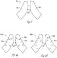
- FIG. 3 is an illustration of an exemplary embodiment of a bowtie antenna 304 for use in a hearing aid, such as hearing aid 100.
- Bowtie antenna 304 can represent an example of bowtie antenna 204 and includes a first conductive plate 310, a second conductive plate 311, and an antenna feed 312 connected to first conductive plate 310 and second conductive plate 311.
- first conductive plate 310 and second conductive plate 311 are substantially symmetric.
- first conductive plate 310 and second conductive plate 311 can be substantially symmetric or substantially asymmetric.
- FIG. 3 illustrates bowtie antenna 304 including first conductive plate 310 and second conductive plate 311 in their flattened state.
- first conductive plate 310 and second conductive plate 311 can be shaped and bent to be positioned within shell 106.
- first conductive plate 310 and second conductive plate 311 can be incorporated into shell 106.
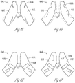
- FIGS. 4A-4F are each an illustration of an exemplary embodiment of the bowtie antenna of FIG. 3 modified to include notches.
- FIGS. 4A-4F each illustrate a bowtie antenna 404 (404A, 404B, 404C, 404D, 404 E, or 404F in FIGS. 4A-4F , respectively) including its two conductive plates 410-411 (410A-411A, 410B-411B, 410C-411C, 410D-411D, 410E-411E, or 410F-411F in FIGS. 4A-4F , respectively) shown in their flattened state.
- Bowtie antenna 404 can represent examples of bowtie antenna 204, and includes antenna feed 312.
- conductive plates 410 and 411 each include a plurality of notches 430 (430A, 430B, 430C, 430D, 430 E, or 430F in FIGS. 4A-4F , respectively).
- at least one of conductive plates 410 and 411 includes one or more notches 430.
- the one or more notches can be configured (e.g., sized, shaped, and positioned in conductive plates 410 and/or 411) based on placement of the plurality of circuit components of hearing aid circuit 102 in shell 106.
- the one or more notches can be configured (e.g., sized, shaped, and positioned in conductive plates 410 and/or 411) to approximately optimize performance of the bowtie antenna for one or more specified frequency bands.
- An example of the one or more specified frequency bands includes the 2.4 GHz Industrial Scientific Medical (ISM) radio band (e.g., with a frequency range of 2.4 GHz - 2.5 GHz and a center frequency of 2.45 GHz).
- ISM Industrial Scientific Medical
- bowtie antenna 404 can be formed by introducing the one or more notches to bowtie antenna 304.
- the introduction of the one or more notches modify the aperture of bowtie antenna 304, such that bowtie antenna 404 has an aperture that is substantially different from that of bowtie antenna 304.
- the one or more notches can each have an approximately triangular, rectangular, circular, or irregular shape, depending on design considerations such as the placement of the circuit components of hearing aid circuit 102 and/or ease of modifying size of each notch for the optimization.
- the one or more notches can be configured (e.g., sized, shaped, and positioned in conductive plates 410 and/or 411) to approximately maximize a radiation efficiency of bowtie antenna 404. In various embodiments, the one or more notches can be configured (e.g., sized, shaped, and positioned in conductive plates 410 and/or 411) to approximately optimize the impedance bandwidth of bowtie antenna 404. In various embodiments, the one or more notches can be configured (e.g., sized, shaped, and positioned in conductive plates 410 and/or 411) to provide bowtie antenna 404 with a specified impedance bandwidth. In various embodiments, the one or more notches can be configured (e.g., sized, shaped, and positioned in conductive plates 410 and/or 411) to approximately to maximize the impedance bandwidth of bowtie antenna 404.
- each of conductive plates 410 and 411 includes one or more notches 430.
- the one or more notches in conductive plate 410 and the one or more notches in conductive plate 411 are substantially symmetric, such as illustrated in FIGS. 4A-4E .
- the one or more notches in conductive plate 410 and the one or more notches in conductive plate 411 are substantially asymmetric, such as illustrated in FIG. 4F .
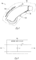
- FIG. 6 is a block diagram illustrating an exemplary embodiment of an antenna interface circuit 614, which can represent an example of antenna interface circuit 214.
- Antenna interface circuit 614 includes a switch 632 and an impedance matching circuit 634.
- Switch 632 provides a first connection between antenna feed 212 and power circuit 226 through impedance matching circuit 634 during battery charging periods and a second connection between antenna feed 212 and communication circuit 218 during communication periods.
- Processing circuit 220 controls timing of the wireless communication and battery charging, and generates timing control signals for the communication periods and battery charging periods.
- FIG. 7 is a block diagram illustrating an exemplary embodiment of an antenna interface circuit 714, which can represent another example of antenna interface circuit 214.
- Antenna interface circuit 714 can provide a connection between bowtie antenna 204 and communication circuit 218 and another connection between bowtie antenna 204 and power circuit 226 when antenna feed 212 includes separate antenna feeds for the wireless communication and the battery charging.
- Antenna interface circuit 714 includes impedance matching circuit 634 connected between the antenna feed for the battery charging (ANTENNA FEED 1) and power circuit 226, and provides a connection between the antenna feed for the wireless communication (ANTENNA FEED 2) and communication circuit 218.
- the present subject matter is used in hearing devices that are configured to communicate with mobile phones.
- the hearing device may be operable to perform one or more of the following: answer incoming calls, hang up on calls, and/or provide two way telephone communications.
- the present subject matter is used in hearing devices configured to communicate with packet-based devices.
- the present subject matter includes hearing devices configured to communicate with streaming audio devices.
- the present subject matter includes hearing devices configured to communicate with Wi-Fi devices.
- the present subject matter includes hearing devices capable of being controlled by remote control devices.
- hearing devices may embody the present subject matter without departing from the scope of the present disclosure.
- the devices depicted in the figures are intended to demonstrate the subject matter, but not necessarily in a limited, exhaustive, or exclusive sense. It is also understood that the present subject matter can be used with a device designed for use in the right ear or the left ear or both ears of the wearer.
- the present subject matter may be employed in hearing devices, such as hearing aids, headsets, headphones, and similar hearing devices.
Landscapes
- Engineering & Computer Science (AREA)
- Computer Networks & Wireless Communication (AREA)
- Health & Medical Sciences (AREA)
- General Health & Medical Sciences (AREA)
- Neurosurgery (AREA)
- Otolaryngology (AREA)
- Physics & Mathematics (AREA)
- Acoustics & Sound (AREA)
- Signal Processing (AREA)
- Circuit For Audible Band Transducer (AREA)
Abstract
Description
- This document relates generally to hearing systems and more particularly to a hearing device with a bowtie antenna.
- Hearing devices provide sound for the wearer. Some examples of hearing devices are headsets, hearing aids, speakers, cochlear implants, bone conduction devices, and personal listening devices. Hearing devices may be capable of performing wireless communication between each other and/or other devices. For example, hearing aids provide amplification to compensate for hearing loss by transmitting amplified sounds to their ear canals. The sounds may be detected from the wearer's environment using the microphone in a hearing aid and/or received from a streaming device via a wireless link. Wireless communication may also be performed for programming the hearing aid and receiving information from the hearing aid. For performing such wireless communication, hearing devices such as hearing aids may each include a wireless transceiver and an antenna.
- A hearing device can perform wireless communication with another device using a bowtie antenna. In various embodiments, the bowtie antenna can include two conductive plates and one or more notches in at least one of the two conductive plates. The one or more notches can be sized, shaped, and/or positioned to approximately optimize performance of the bowtie antenna for one or more frequency bands of the wireless communication. In various embodiments, the hearing device can receive energy using the bowtie antenna and charge a rechargeable battery using the received energy.
- In an exemplary embodiment, a hearing device include an electronic circuit and a shell housing at least portions of the electronic circuit. The electronic circuit can receive one or more input signals, produce an output sound using the received one or more input signals, and transmit the output sound to the wearer. The electronic circuit can include a bowtie antenna and a communication circuit. The bowtie antenna can include a first conductive plate, a second conductive plate, one or more notches in at least one of the first conductive plate and the second conductive plate, and an antenna feed connected to the first conductive plate and the second conductive plate. The one or more notches can be configured to approximately optimize performance of wireless communication for one or more specified frequency bands. The communication circuit can perform the wireless communication using the bowtie antenna
- In an exemplary embodiment, a hearing device include an electronic circuit and a shell housing at least portions of the electronic circuit. The electronic circuit can receive one or more input signals, produce an output sound using the received one or more input signals, and transmit the output sound to the wearer. The electronic circuit can include a bowtie antenna, a communication circuit, a rechargeable battery, and a power circuit. The bowtie antenna include a first conductive plate, a second conductive plate, and an antenna feed connected to the first conductive plate and the second conductive plate. The communication circuit can perform wireless communication using the bowtie antenna. The power circuit can receive energy using the bowtie antenna and charge the rechargeable battery using the received energy.
- In an exemplary embodiment, a method for operating a hearing device is provided. The method can include receiving one or more input signals, processing the received one or more input signals to produce one or more output signals using a processing circuit of the hearing device, and producing an output sound using a first output signal using a receiver of the hearing device. A first input signal of the one or more input signals can be received via wireless communication using a communication circuit of the hearing device coupled to a bowtie antenna of the hearing device. The bowtie antenna can include a first conductive plate, a second conductive plate, and one or more notches in at least one of the first conductive plate and the second conductive plate, the one or more notches configured to approximately optimize a parameter for one or more specified frequency bands of the wireless communication. The parameter is associated with performance of the wireless communication.
- This summary is an overview of some of the teachings of the present application and not intended to be an exclusive or exhaustive treatment of the present subject matter. Further details about the present subject matter are found in the detailed description and appended claims. The scope of the present invention is defined by the appended claims and their legal equivalents.
-
-
FIG. 1 is an illustration of an exemplary embodiment of portions of a hearing aid including a bowtie antenna. -
FIG. 2 is a block diagram illustrating an exemplary embodiment of portions of a circuit of a hearing aid, such as the hearing aid ofFIG. 1 . -
FIG. 3 is an illustration of an exemplary embodiment of a bowtie antenna for use in a hearing aid, such as the hearing aid ofFIG. 1 . -
FIGS. 4A-4F are each an illustration of an exemplary embodiment of the bowtie antenna ofFIG. 3 modified to include notches. -
FIG. 5 is an illustration of an exemplary embodiment of portions of a hearing aid including a bowtie antenna having an approximately maximized size. -
FIG. 6 is a block diagram illustrating an exemplary embodiment of an antenna interface circuit of the hearing device. -
FIG. 7 is a block diagram illustrating another exemplary embodiment of the antenna interface circuit. -
FIG. 8 is an illustration of an exemplary embodiment of portions of a hearing aid including a bowtie antenna with dual feeds for wireless communication and battery charging. -
FIG. 9 is a circuit schematic illustrating an exemplary embodiment of an impedance matching circuit of the antenna interface circuit. - The following detailed description of the present subject matter refers to subject matter in the accompanying drawings which show, by way of illustration, specific aspects and embodiments in which the present subject matter may be practiced. These embodiments are described in sufficient detail to enable those skilled in the art to practice the present subject matter. References to "an", "one", or "various" embodiments in this disclosure are not necessarily to the same embodiment, and such references contemplate more than one embodiment. The following detailed description is demonstrative and not to be taken in a limiting sense. The scope of the present subject matter is defined by the appended claims, along with the full scope of legal equivalents to which such claims are entitled.
- This document discusses, among other things, a hearing device including a bowtie antenna optimized for wireless communication. In various embodiments, the bowtie antenna can allow for ear-to-ear communication with another hearing device worn by the same wearer and/or communication with another device capable of communication with the hearing device, such as a programming device, a cellphone, an audio streaming device, a device configured to send one or more types of notification to the wearer, and a device configured to allow the wearer to use the hearing device as a remote controller. In various embodiments, the hearing device is powered by a rechargeable battery and can include a battery charging circuit that receives energy using the bowtie antenna.
- A bowtie antenna (also spelled as "bow-tie antenna" or "bow tie antenna") can include two conductive objects and be fed at a gap between the two conductive objects. Each conductive object can be formed by one or more conductive (e.g., metal) wires or plates. Examples of the bowtie antenna as used in hearing aids are discussed in
U.S. Patent Application No. 14/706,173 - Performance of an antenna in wireless communication, such as its radiation efficiency, depends on impedance matching between the feed point of the antenna and the output of the communication circuit such as a transceiver. The impendence of the antenna is a function of the operating frequency of the wireless communication. When used in a hearing device that is to be worn on a wearer's head, such as in a hearing aid to be worn in or about an ear of the wearer, the impedance of the antenna can be substantially affected by the presence of human tissue. Such effect is known as head loading and can make the performance of the antenna when the hearing device is worn (referred to as "on head performance") substantially different from the performance of the antenna when the hearing device is not worn. Impedance of the antenna including effect of head loading depends on configuration and placement of the antenna, which are constrained by size and placement of other components of the hearing device. When a pair of binaural hearing devices are worn by the wearer, asymmetric antenna performances of the hearing devices worn on the right and left side of the wearer's head may result from placement of components in these hearing devices. Such factors contribute to difficulty in impedance matching and hence limit realized gain of the antenna.
- A hearing device such as a hearing aid can be powered by a rechargeable battery. The rechargeable battery can be wirelessly recharged using a recharging device magnetically or electromagnetically coupled to a battery charging circuit in the hearing device, eliminating the need for removing battery from the hearing device for recharging. An antenna is needed to receive the energy magnetically or electromagnetically transmitted to the hearing aid. Separate antennas can be used for the wireless communication and battery charging, but using an additional antenna in a hearing device such as hearing aid may be undesirable.
- The present subject matter provides for optimization of the bowtie antenna for specific frequency bands by introducing one or more notches to modify aperture of the antenna. In various embodiments, the one or more notches can be sized, shaped, and placed on the conductive plates of the bowtie antenna based on placement of other components in the hearing device and on head performance of the wireless communication using the antenna. For example, shape, size and placement of each notch can initially be selected based on available space in the hearing device, and then manipulated to achieve the desired performance of the wireless communication. When notches are placed in both conductive plates of the bowtie antenna, the placement can be symmetric or asymmetric, depending on specific hearing device configuration and available space as determined by the placement of other components. In various embodiments, the aperture of the antenna can be modified by the notches to broaden impedance bandwidth for better impedance matching. The broadened impedance bandwidth may also reduce the antenna performance asymmetry when a pair of binaural hearing devices are worn by the wearer. An experiment showed that introduction of notches to a bowtie antenna improved antenna performance of a hearing aid by reducing the resonance at 4.8 GHz (harmonic) and improving the resonance at 2.4 GHz (operation frequency), and the notched bowtie antenna provided a broader impedance bandwidth that resulted in a better realized antenna gain. In various embodiments, notches can be made in a different manner depending upon design considerations specific to each hearing device. In various embodiments, the antenna performance can be further improved by increasing or approximately maximizing physical aperture of the bowtie antenna within the design constraints of the hearing device. In some embodiments, the bowtie antenna can be used for both wireless communication and battery charging. The bowtie antenna can be optimized (e.g., notched) for a dual-band application, with a first frequency band for the wireless communication and a substantially different second frequency band for the battery charging. The bowtie antenna can be dual fed or can be controllably connected to one of the communication and battery charging circuits using a switch. The antenna can be tuned for battery charging in free space when the rechargeable battery is to be charged while the hearing device is not being worn.
- While application in a hearing aid is specifically discussed as an example, the present subject matter can be applied in any hearing device capable of wireless communication using a bowtie antenna. In various embodiments, the bowtie antenna can be sized, shaped, and placed in the hearing device, such as contained within or incorporated into a housing of the hearing device.
-
FIG. 1 is an illustration of an exemplary embodiment of portions of ahearing aid 100 including abowtie antenna 104.Hearing aid 100 includes ahearing aid circuit 102, which is an electronic circuit that can receive one or more input signals and produce an output sound using the received one or more input signals. Portions of the electronic circuit, which include a plurality of circuit components, can be housed in ashell 106. In the illustrated embodiment,shell 106 allows hearingaid 100 to reside substantially behind or over an ear of a wearer when being worn by the wearer.Shell 106 is configured for use in a behind-the-ear (BTE) type hearing aid, a receiver-in-canal (RIC) type hearing aid, or a receiver-in-the-ear (RITE) type hearing aid. In various embodiments,shell 106 can be configured for use in any type of hearing device, including any type of hearing aid, in which a bowtie antenna is suitable for placement and use for wireless communication. -
Hearing aid circuit 102 can perform wireless communication usingbowtie antenna 104. In various embodiments,bowtie antenna 104 can include one ormore notches 130 in its conductive structure to approximately optimize performance of the wireless communication for one or more specified frequency bands. In some embodiments,hearing aid 100 can include a rechargeable battery.Hearing aid circuit 102 can receive energy usingbowtie antenna 104, and can charge the rechargeable battery using the received energy. -
FIG. 2 is a block diagram illustrating an exemplary embodiment of portions of ahearing aid circuit 202, which can be an example of hearingaid circuit 102.Hearing aid circuit 202 can represent an example of portions of a circuit of hearingaid 100, and can include amicrophone 216, acommunication circuit 218, abowtie antenna 204, anantenna interface circuit 214, aprocessing circuit 220, a receiver (speaker) 222, abattery 224, and apower circuit 226.Microphone 216 can receive sounds from the environment of the wearer of hearingaid 100.Communication circuit 218 can communicate with another device wirelessly usingbowtie antenna 204, including receiving programming codes, streamed audio signals, and/or other audio signals and transmitting programming codes, audio signals, and/or other signals. Examples of the other device can include the other hearing aid of a pair of hearing aids for the same wearer, a hearing aid host device, an audio streaming device, a telephone, and other devices capable of communicating with hearing aids wirelessly.Antenna interface circuit 214 provides an interface, such as impedance matching, betweenbowtie antenna 204 andcommunication circuit 218 and betweenbowtie antenna 204 andpower circuit 226.Processing circuit 220 can control the operation of hearingaid 100 using the programming codes and processes the sounds received bymicrophone 216 and/or the audio signals received bycommunication circuit 218 to produce output signals.Receiver 222 can generate output sounds using the output signals and transmit the output sounds to an ear canal of the wearer.Battery 224 andpower circuit 226 constitute the power source for the operation of hearingaid circuit 202. In some embodiments,power circuit 226 can include a power management circuit. In some embodiments,battery 224 can include a rechargeable battery, andpower circuit 226 can include a battery charging circuit that can receive energy transmitted to hearingaid 100 usingantenna 204 and charge the rechargeable battery using the received energy. -
Bowtie 204 can include a firstconductive plate 210, a secondconductive plate 211, and an antenna feed (as referred to as feed point) 212 connected to firstconductive plate 210 and secondconductive plate 211. In various embodiment, firstconductive plate 210 and secondconductive plate 211 can each include a conductive sheet (rather than one or more wires).Bowtie antenna 104 can represent an example ofbowtie antenna 204 as configured and placed in a hearing aid. -
FIG. 3 is an illustration of an exemplary embodiment of a bowtie antenna 304 for use in a hearing aid, such ashearing aid 100. Bowtie antenna 304 can represent an example ofbowtie antenna 204 and includes a firstconductive plate 310, a secondconductive plate 311, and anantenna feed 312 connected to firstconductive plate 310 and secondconductive plate 311. In the illustrated embodiment, firstconductive plate 310 and secondconductive plate 311 are substantially symmetric. In various embodiments, firstconductive plate 310 and secondconductive plate 311 can be substantially symmetric or substantially asymmetric. -
FIG. 3 illustrates bowtie antenna 304 including firstconductive plate 310 and secondconductive plate 311 in their flattened state. In various embodiments when bowtie antenna 304 is placed in hearingaid 100, firstconductive plate 310 and secondconductive plate 311 can be shaped and bent to be positioned withinshell 106. In various other embodiments, firstconductive plate 310 and secondconductive plate 311 can be incorporated intoshell 106. -
FIGS. 4A-4F are each an illustration of an exemplary embodiment of the bowtie antenna ofFIG. 3 modified to include notches.FIGS. 4A-4F each illustrate a bowtie antenna 404 (404A, 404B, 404C, 404D, 404 E, or 404F inFIGS. 4A-4F , respectively) including its two conductive plates 410-411 (410A-411A, 410B-411B, 410C-411C, 410D-411D, 410E-411E, or 410F-411F inFIGS. 4A-4F , respectively) shown in their flattened state. Bowtie antenna 404 can represent examples ofbowtie antenna 204, and includesantenna feed 312. In the illustrated embodiments, conductive plates 410 and 411 each include a plurality of notches 430 (430A, 430B, 430C, 430D, 430 E, or 430F inFIGS. 4A-4F , respectively). In various embodiments, at least one of conductive plates 410 and 411 includes one or more notches 430. In various embodiments, the one or more notches can be configured (e.g., sized, shaped, and positioned in conductive plates 410 and/or 411) based on placement of the plurality of circuit components of hearingaid circuit 102 inshell 106. In various embodiments, the one or more notches can be configured (e.g., sized, shaped, and positioned in conductive plates 410 and/or 411) to approximately optimize performance of the bowtie antenna for one or more specified frequency bands. An example of the one or more specified frequency bands includes the 2.4 GHz Industrial Scientific Medical (ISM) radio band (e.g., with a frequency range of 2.4 GHz - 2.5 GHz and a center frequency of 2.45 GHz). - In various embodiments, bowtie antenna 404 can be formed by introducing the one or more notches to bowtie antenna 304. The introduction of the one or more notches modify the aperture of bowtie antenna 304, such that bowtie antenna 404 has an aperture that is substantially different from that of bowtie antenna 304. The one or more notches can each have an approximately triangular, rectangular, circular, or irregular shape, depending on design considerations such as the placement of the circuit components of hearing
aid circuit 102 and/or ease of modifying size of each notch for the optimization. In various embodiments, the one or more notches can be configured (e.g., sized, shaped, and positioned in conductive plates 410 and/or 411) to approximately maximize a radiation efficiency of bowtie antenna 404. In various embodiments, the one or more notches can be configured (e.g., sized, shaped, and positioned in conductive plates 410 and/or 411) to approximately optimize the impedance bandwidth of bowtie antenna 404. In various embodiments, the one or more notches can be configured (e.g., sized, shaped, and positioned in conductive plates 410 and/or 411) to provide bowtie antenna 404 with a specified impedance bandwidth. In various embodiments, the one or more notches can be configured (e.g., sized, shaped, and positioned in conductive plates 410 and/or 411) to approximately to maximize the impedance bandwidth of bowtie antenna 404. - In various embodiments, each of conductive plates 410 and 411 includes one or more notches 430. In various embodiments, the one or more notches in conductive plate 410 and the one or more notches in conductive plate 411 are substantially symmetric, such as illustrated in
FIGS. 4A-4E . In various embodiments, the one or more notches in conductive plate 410 and the one or more notches in conductive plate 411 are substantially asymmetric, such as illustrated inFIG. 4F . -
FIG. 5 is an illustration of an exemplary embodiment of portions of ahearing aid 500 including abowtie antenna 504 having an approximately maximized size.Hearing aid 500 can represent an example of hearingaid 100.Bowtie antenna 504 can represent an example ofbowtie antenna 204. In various embodiments, the conductive plates ofbowtie antenna 504 can be approximately maximized to approximately maximize the aperture ofantenna 504, thereby improving efficiency of the antenna. In various embodiments, one or more notches such as notches 430 can be introduced tobowtie antenna 504 to approximately optimize performance ofbowtie antenna 504 in manners discussed above for bowtie antenna 404. -
FIG. 6 is a block diagram illustrating an exemplary embodiment of anantenna interface circuit 614, which can represent an example ofantenna interface circuit 214.Antenna interface circuit 614 includes aswitch 632 and animpedance matching circuit 634.Switch 632 provides a first connection betweenantenna feed 212 andpower circuit 226 throughimpedance matching circuit 634 during battery charging periods and a second connection betweenantenna feed 212 andcommunication circuit 218 during communication periods.Processing circuit 220 controls timing of the wireless communication and battery charging, and generates timing control signals for the communication periods and battery charging periods. -
FIG. 7 is a block diagram illustrating an exemplary embodiment of anantenna interface circuit 714, which can represent another example ofantenna interface circuit 214.Antenna interface circuit 714 can provide a connection betweenbowtie antenna 204 andcommunication circuit 218 and another connection betweenbowtie antenna 204 andpower circuit 226 whenantenna feed 212 includes separate antenna feeds for the wireless communication and the battery charging.Antenna interface circuit 714 includesimpedance matching circuit 634 connected between the antenna feed for the battery charging (ANTENNA FEED 1) andpower circuit 226, and provides a connection between the antenna feed for the wireless communication (ANTENNA FEED 2) andcommunication circuit 218. -
FIG. 8 is an illustration of an exemplary embodiment of portions of ahearing aid 800.Hearing aid 800 can represent an example of hearingaid 100 and can include abowtie antenna 804 with dual antenna feeds 812A and 812B for the wireless communication and the battery charging. Antenna feeds 812A and 812B are examples of theANTENNA FEED 1 andANTENNA FEED 2 shown inFIG. 7 . In various embodiments, except for antenna feeds 812A and 812B,bowtie antenna 804 can be substantially identical tobowtie antenna 304, 404, or 504. In other words,bowtie antenna 804 can include conductive plates 310-311 or 410-411, with the one or more notches as discussed above with reference toFIG. 4 , and/or with approximately maximized aperture as discussed above with reference toFIG. 5 . -
FIG. 9 is a circuit schematic illustrating an exemplary embodiment of animpedance matching circuit 934.Impedance matching circuit 934 can represent an example ofimpedance matching circuit 634 and include capacitors C1 and C2. In various embodiments,impedance matching circuit 934 can function as an impedance matching network between the input impedance ofpower circuit 226 and the impedance ofbowtie antenna 204. In various embodiments, the one or more notches 430 are configured to approximately optimize the impedance ofbowtie antenna 204 such that the impedance matching betweenpower circuit 226 andbowtie antenna 204 is approximately optimized. For example, the one or more notches 430 are configured to approximately maximize the impedance bandwidth ofbowtie antenna 204 such that the impedance matching is less sensitive to variations in the frequency of the wireless communication during operation of hearingaid 100. - Hearing devices typically include at least one enclosure or housing, a microphone, hearing device electronics including processing electronics, and a speaker or "receiver." Hearing devices may include a power source, such as a battery. In various embodiments, the battery may be rechargeable. In various embodiments, multiple energy sources may be employed. It is understood that in various embodiments the microphone is optional. It is understood that in various embodiments the receiver is optional. It is understood that variations in communications protocols, antenna configurations, and combinations of components may be employed without departing from the scope of the present subject matter. Antenna configurations may vary and may be included within an enclosure for the electronics or be external to an enclosure for the electronics. Thus, the examples set forth herein are intended to be demonstrative and not a limiting or exhaustive depiction of variations.
- It is understood that digital hearing aids include a processor. In digital hearing aids with a processor, programmable gains may be employed to adjust the hearing aid output to a wearer's particular hearing impairment. The processor may be a digital signal processor (DSP), microprocessor, microcontroller, other digital logic, or combinations thereof. The processing may be done by a single processor, or may be distributed over different devices. The processing of signals referenced in this application can be performed using the processor or over different devices. Processing may be done in the digital domain, the analog domain, or combinations thereof. Processing may be done using subband processing techniques. Processing may be done using frequency domain or time domain approaches. Some processing may involve both frequency and time domain aspects. For brevity, in some examples drawings may omit certain blocks that perform frequency synthesis, frequency analysis, analog-to-digital conversion, digital-to-analog conversion, amplification, buffering, and certain types of filtering and processing. In various embodiments the processor is adapted to perform instructions stored in one or more memories, which may or may not be explicitly shown. Various types of memory may be used, including volatile and nonvolatile forms of memory. In various embodiments, the processor or other processing devices execute instructions to perform a number of signal processing tasks. Such embodiments may include analog components in communication with the processor to perform signal processing tasks, such as sound reception by a microphone, or playing of sound using a receiver (i.e., in applications where such transducers are used). In various embodiments, different realizations of the block diagrams, circuits, and processes set forth herein can be created by one of skill in the art without departing from the scope of the present subject matter.
- Various embodiments of the present subject matter support wireless communications with a hearing device. In various embodiments the wireless communications can include standard or nonstandard communications. Some examples of standard wireless communications include, but not limited to, Bluetooth™, low energy Bluetooth, IEEE 802.11(wireless LANs), 802.15 (WPANs), and 802.16 (WiMAX). Cellular communications may include, but not limited to, CDMA, GSM, ZigBee, and ultra-wideband (UWB) technologies. In various embodiments, the communications are radio frequency communications. In various embodiments the communications are optical communications, such as infrared communications. In various embodiments, the communications are inductive communications. In various embodiments, the communications are ultrasound communications. Although embodiments of the present system may be demonstrated as radio communication systems, it is possible that other forms of wireless communications can be used. It is understood that past and present standards can be used. It is also contemplated that future versions of these standards and new future standards may be employed without departing from the scope of the present subject matter.
- The wireless communications support a connection from other devices. Such connections include, but are not limited to, one or more mono or stereo connections or digital connections having link protocols including, but not limited to 802.3 (Ethernet), 802.4, 802.5, USB, ATM, Fibre-channel, Firewire or 1394, InfiniBand, or a native streaming interface. In various embodiments, such connections include all past and present link protocols. It is also contemplated that future versions of these protocols and new protocols may be employed without departing from the scope of the present subject matter.
- In various embodiments, the present subject matter is used in hearing devices that are configured to communicate with mobile phones. In such embodiments, the hearing device may be operable to perform one or more of the following: answer incoming calls, hang up on calls, and/or provide two way telephone communications. In various embodiments, the present subject matter is used in hearing devices configured to communicate with packet-based devices. In various embodiments, the present subject matter includes hearing devices configured to communicate with streaming audio devices. In various embodiments, the present subject matter includes hearing devices configured to communicate with Wi-Fi devices. In various embodiments, the present subject matter includes hearing devices capable of being controlled by remote control devices.
- It is further understood that different hearing devices may embody the present subject matter without departing from the scope of the present disclosure. The devices depicted in the figures are intended to demonstrate the subject matter, but not necessarily in a limited, exhaustive, or exclusive sense. It is also understood that the present subject matter can be used with a device designed for use in the right ear or the left ear or both ears of the wearer.
- The present subject matter may be employed in hearing devices, such as hearing aids, headsets, headphones, and similar hearing devices.
- The present subject matter may be employed in hearing devices having additional sensors. Such sensors include, but are not limited to, magnetic field sensors, telecoils, temperature sensors, accelerometers and proximity sensors.
- The present subject matter is demonstrated for hearing devices, including hearing aids, including but not limited to, behind-the-ear (BTE), in-the-ear (ITE), in-the-canal (ITC), receiver-in-canal (RIC), or completely-in-the-canal (CIC) type hearing aids. It is understood that behind-the-ear type hearing aids may include devices that reside substantially behind the ear or over the ear. Such devices may include hearing aids with receivers associated with the electronics portion of the behind-the-ear device, or hearing aids of the type having receivers in the ear canal of the user, including but not limited to receiver-in-canal (RIC) or receiver-in-the-ear (RITE) designs. The present subject matter can also be used in hearing assistance devices generally, such as cochlear implant type hearing devices. The present subject matter can also be used in deep insertion devices having a transducer, such as a receiver or microphone. The present subject matter can be used in devices whether such devices are standard or custom fit and whether they provide an open or an occlusive design. It is understood that other hearing devices not expressly stated herein may be used in conjunction with the present subject matter.
- This application is intended to cover adaptations or variations of the present subject matter. It is to be understood that the above description is intended to be illustrative, and not restrictive. The scope of the present subject matter should be determined with reference to the appended claims, along with the full scope of legal equivalents to which such claims are entitled.
Claims (15)
- A hearing device configured to be worn by a wearer, comprising:an electronic circuit configured to receive one or more input signals, produce an output sound using the received one or more input signals, and transmit the output sound to the wearer, the electronic circuit including:a bowtie antenna including a first conductive plate, a second conductive plate, one or more notches in at least one of the first conductive plate and the second conductive plate, and an antenna feed connected to the first conductive plate and the second conductive plate, the one or more notches configured to approximately optimize performance of wireless communication for one or more specified frequency bands; anda communication circuit coupled to the antenna feed, the communication circuit configured to perform the wireless communication using the bowtie antenna; anda shell housing at least portions of the electronic circuit.
- The hearing device according to claim 1, wherein the electronic circuit further comprises:a rechargeable battery; anda power circuit coupled to the antenna feed, the power circuit configured to receive energy using the bowtie antenna and charge the rechargeable battery using the received energy.
- The hearing device according to claim 2, wherein the electronic circuit further comprises:a switch coupled to the antenna feed, the switch configured to provide a first connection between the antenna feed and the communication circuit during communication periods and a second connection between the antenna feed and the power circuit during battery charging periods; anda processing circuit configured to control the communication periods and the battery charging periods.
- The hearing device according to any of the preceding claims, wherein the first conductive plate and the second conductive plate are each shaped and bent to be positioned within the shell.
- The hearing device according to any of the preceding claims, wherein the electronic circuit comprises a plurality of circuit components, and the one or more notches are sized, shaped, and positioned to accommodate placement of the plurality of circuit components in the shell.
- The hearing device according to any of the preceding claims, wherein the one or more notches comprise one or more first notches in the first conductive plate and one or more second notches in the second conductive plate, and the one or more first notches and the one or more second notches are substantially asymmetric.
- The hearing device according to any of the preceding claims, wherein the one or more notches are configured to approximately maximize a radiation efficiency of the bowtie antenna.
- The hearing device according to any of claims 1 to 6, wherein the one or more notches are configured to approximately optimize an impedance bandwidth of the bowtie antenna.
- The hearing device according to any of the preceding claims, wherein the hearing device comprises a hearing aid, and the shell is configured to allow the hearing device to reside substantially behind or over an ear of the wearer when being worn by the wearer.
- A method for operating a hearing device, the method comprising:receiving one or more input signals, including receiving a first input signal of the one or more input signals via wireless communication using a communication circuit of the hearing device coupled to a bowtie antenna of the hearing device, the bowtie antenna including a first conductive plate, a second conductive plate, and one or more notches in at least one of the first conductive plate and the second conductive plate, the one or more notches configured to approximately optimize a parameter for one or more specified frequency bands of the wireless communication, the parameter associated with performance of the wireless communication;processing the received one or more input signals to produce one or more output signals using a processing circuit of the hearing device; andproducing an output sound using a first output signal of the one or more output signal using a receiver of the hearing device.
- The method according to claim 10, further comprising transmitting a second output signal of the one or more output signal to another device via the wireless communication using the communication circuit and the bowtie antenna.
- The method according to any of claims 10 and 11, further comprising:receiving energy wirelessly transmitted to the hearing device using a power circuit of the hearing device coupled to the bowtie antenna; andcharging a rechargeable battery of the hearing device using the received energy.
- The method according to any of claims 11 and 12, comprising receiving the first input signal and transmitting the second output signal via the wireless communication using the communication circuit coupled to the bowtie antenna with the one or more notches sized, shaped, and positioned in at least one of the first conductive plate and the second conductive plate to approximately optimize the impedance bandwidth of the bowtie antenna for impedance matching.
- The method according to any of claims 11 to 13, comprising receiving the first input signal and transmitting the second output signal via the wireless communication using the communication circuit coupled to the bowtie antenna with one or more first notches of the one or more notches positioned in the first conductive plate and one or more second notches of the one or more notches positioned in the second conductive plate, the one or more first notches and the one or more second notches positioned in an asymmetric manner.
- The method according to any of claims 10 to 14, comprising receiving the one or more input signals and processing the received one or more input signals to produce one or more output signals using portions of an electronic circuit housed in a shell configured to allow the hearing device to reside substantially behind or over an ear of a wearer when being worn by the wearer, the portions of the electronic including the communication circuit, the bowtie antenna, and the processor.
Applications Claiming Priority (1)
| Application Number | Priority Date | Filing Date | Title |
|---|---|---|---|
| US15/331,077 US10297910B2 (en) | 2016-10-21 | 2016-10-21 | Hearing device with bowtie antenna optimized for specific band |
Publications (2)
| Publication Number | Publication Date |
|---|---|
| EP3313096A1 true EP3313096A1 (en) | 2018-04-25 |
| EP3313096B1 EP3313096B1 (en) | 2020-07-15 |
Family
ID=60083162
Family Applications (1)
| Application Number | Title | Priority Date | Filing Date |
|---|---|---|---|
| EP17196023.0A Active EP3313096B1 (en) | 2016-10-21 | 2017-10-11 | Hearing device with bowtie antenna optimized for specific band |
Country Status (2)
| Country | Link |
|---|---|
| US (1) | US10297910B2 (en) |
| EP (1) | EP3313096B1 (en) |
Cited By (9)
| Publication number | Priority date | Publication date | Assignee | Title |
|---|---|---|---|---|
| EP3627846A3 (en) * | 2018-06-05 | 2020-04-22 | Starkey Laboratories, Inc. | Ear-worn electronic device incorporating chip antenna loading of antenna structure |
| WO2020123233A1 (en) * | 2018-12-10 | 2020-06-18 | Starkey Laboratories, Inc. | Ear-worn electronic hearing device incorporating an antenna with cutouts |
| US10804599B2 (en) | 2016-12-20 | 2020-10-13 | Sonova Ag | BTE hearing instrument comprising a loop antenna |
| US10931005B2 (en) | 2018-10-29 | 2021-02-23 | Starkey Laboratories, Inc. | Hearing device incorporating a primary antenna in conjunction with a chip antenna |
| US10951997B2 (en) | 2018-08-07 | 2021-03-16 | Starkey Laboratories, Inc. | Hearing device incorporating antenna arrangement with slot radiating element |
| EP3813386A1 (en) * | 2019-10-25 | 2021-04-28 | GN Hearing A/S | A hearing device with active antenna switching |
| EP3836565A1 (en) * | 2019-12-12 | 2021-06-16 | Sivantos Pte. Ltd. | Circuit board for a hearing device |
| WO2021115790A1 (en) * | 2019-12-12 | 2021-06-17 | Widex A/S | Hearing assistive device having a rechargeable battery |
| US11902748B2 (en) | 2018-08-07 | 2024-02-13 | Starkey Laboratories, Inc. | Ear-worn electronic hearing device incorporating an antenna with cutouts |
Families Citing this family (4)
| Publication number | Priority date | Publication date | Assignee | Title |
|---|---|---|---|---|
| US20160330552A1 (en) * | 2015-05-07 | 2016-11-10 | Starkey Laboratories, Inc. | Hearing aid bowtie antenna optimized for ear to ear communications |
| US10256529B2 (en) * | 2016-11-15 | 2019-04-09 | Starkey Laboratories, Inc. | Hearing device incorporating conformal folded antenna |
| US10631109B2 (en) | 2017-09-28 | 2020-04-21 | Starkey Laboratories, Inc. | Ear-worn electronic device incorporating antenna with reactively loaded network circuit |
| US20240030592A1 (en) * | 2022-07-20 | 2024-01-25 | Starkey Laboratories, Inc. | Antenna designs for hearing instruments |
Citations (3)
| Publication number | Priority date | Publication date | Assignee | Title |
|---|---|---|---|---|
| US20150030190A1 (en) * | 2013-05-01 | 2015-01-29 | Starkey Laboratories, Inc. | Hearing assistance device with antenna optimized to reduce head loading |
| EP2835862A1 (en) * | 2013-08-08 | 2015-02-11 | Nxp B.V. | Antenna |
| US20160050502A1 (en) * | 2014-08-15 | 2016-02-18 | Gn Resound A/S | Hearing aid with an antenna |
Family Cites Families (22)
| Publication number | Priority date | Publication date | Assignee | Title |
|---|---|---|---|---|
| US3369245A (en) | 1964-12-10 | 1968-02-13 | Technical Appliance Corp | Wing type dipole with end mounted stubs |
| US5721783A (en) | 1995-06-07 | 1998-02-24 | Anderson; James C. | Hearing aid with wireless remote processor |
| US6594370B1 (en) | 1999-07-16 | 2003-07-15 | James C. Anderson | Wireless personal communication apparatus in the form of a necklace |
| US6710744B2 (en) | 2001-12-28 | 2004-03-23 | Zarlink Semiconductor (U.S.) Inc. | Integrated circuit fractal antenna in a hearing aid device |
| US7289853B1 (en) | 2003-08-28 | 2007-10-30 | David Campbell | High frequency wireless pacemaker |
| US20050099341A1 (en) | 2003-11-12 | 2005-05-12 | Gennum Corporation | Antenna for a wireless hearing aid system |
| ATE508590T1 (en) | 2004-02-19 | 2011-05-15 | Oticon As | HEARING AID WITH ANTENNA FOR RECEIVING AND TRANSMITTING ELECTROMAGNETIC SIGNALS AND SHIELDING BATTERY |
| DE102005008063B4 (en) | 2005-02-22 | 2008-05-15 | Fraunhofer-Gesellschaft zur Förderung der angewandten Forschung e.V. | antenna |
| US20080218293A1 (en) | 2005-04-22 | 2008-09-11 | Nxp B.V. | High Frequency Electromagnetic Wave Receiver and Broadband Waveguide Mixer |
| CA2645885A1 (en) | 2007-12-06 | 2009-06-06 | Emma Mixed Signal C.V. | Miniature antenna for wireless communications |
| US20090214064A1 (en) | 2008-02-25 | 2009-08-27 | Zounds, Inc. | RF power supply for hearing aids |
| JP5718315B2 (en) | 2010-03-23 | 2015-05-13 | 古河電気工業株式会社 | Antenna and integrated antenna |
| US8483415B2 (en) | 2010-06-18 | 2013-07-09 | Motorola Mobility Llc | Antenna system with parasitic element for hearing aid compliant electromagnetic emission |
| US9432780B2 (en) | 2010-07-03 | 2016-08-30 | Starkey Laboratories, Inc. | Multi-mode radio for hearing assistance devices |
| DK2725655T3 (en) | 2010-10-12 | 2021-09-20 | Gn Hearing As | Antenna system for a hearing aid |
| SG192907A1 (en) | 2011-02-28 | 2013-09-30 | Widex As | Hearing aid and a method of driving an output stage |
| US20130343586A1 (en) | 2012-06-25 | 2013-12-26 | Gn Resound A/S | Hearing aid having a slot antenna |
| US8878735B2 (en) | 2012-06-25 | 2014-11-04 | Gn Resound A/S | Antenna system for a wearable computing device |
| DK2932560T4 (en) | 2012-12-12 | 2020-12-14 | Sivantos Pte Ltd | Folded dipole for hearing aid |
| US10743116B2 (en) | 2013-04-30 | 2020-08-11 | Starkey Laboratories, Inc. | Small loop antenna with shorting conductors for hearing assistance devices |
| DE102014201118A1 (en) | 2014-01-22 | 2015-07-23 | Siemens Aktiengesellschaft | Dual antenna system for charging one or more hearing aids |
| US20160330552A1 (en) | 2015-05-07 | 2016-11-10 | Starkey Laboratories, Inc. | Hearing aid bowtie antenna optimized for ear to ear communications |
-
2016
- 2016-10-21 US US15/331,077 patent/US10297910B2/en active Active
-
2017
- 2017-10-11 EP EP17196023.0A patent/EP3313096B1/en active Active
Patent Citations (3)
| Publication number | Priority date | Publication date | Assignee | Title |
|---|---|---|---|---|
| US20150030190A1 (en) * | 2013-05-01 | 2015-01-29 | Starkey Laboratories, Inc. | Hearing assistance device with antenna optimized to reduce head loading |
| EP2835862A1 (en) * | 2013-08-08 | 2015-02-11 | Nxp B.V. | Antenna |
| US20160050502A1 (en) * | 2014-08-15 | 2016-02-18 | Gn Resound A/S | Hearing aid with an antenna |
Non-Patent Citations (5)
| Title |
|---|
| ANGELOPOULOS E S ET AL: "A modified bow-tie slot antenna fed by a CPW-to-CPW transition loaded with inductively coupled slots for ultra wide - band applications", 2005 IEEE INTERNATIONAL WORKSHOP ON ANTENNA TECHNOLOGY ; IEEE IWAT 2005 ; MARINA MANDARIN HOTEL, SINGAPORE, MARCH 7 - 9, 2005, IEEE OPERATIONS CENTER, PISCATAWAY, NJ, 7 March 2005 (2005-03-07), pages 513 - 516, XP010813215, ISBN: 978-0-7803-8842-0, DOI: 10.1109/IWAT.2005.1461129 * |
| DUSHYANTT GARG ET AL: "Multi band compact bow-tie slot antenna for WLAN applications", ELECTROMAGNETIC COMPATIBILITY (APEMC), 2012 ASIA-PACIFIC SYMPOSIUM ON, IEEE, 21 May 2012 (2012-05-21), pages 597 - 600, XP032199541, ISBN: 978-1-4577-1557-0, DOI: 10.1109/APEMC.2012.6237883 * |
| HUANG C-Y ET AL: "Multiple band-stop bow-tie slot antennas for multiband wireless systems", IET MICROWAVES ANTENNAS & PROPAGA,, vol. 2, no. 6, 8 September 2008 (2008-09-08), pages 588 - 593, XP006031667, ISSN: 1751-8733, DOI: 10.1049/IET-MAP:20070177 * |
| MATHEW JIBISH ET AL: "A modified bow-tie antenna for dual band RFID applications", 2015 IEEE 9TH INTERNATIONAL CONFERENCE ON INTELLIGENT SYSTEMS AND CONTROL (ISCO), IEEE, 9 January 2015 (2015-01-09), pages 1 - 3, XP033219491, DOI: 10.1109/ISCO.2015.7282326 * |
| YU-WEI LIU ET AL: "Metal strip-embedded slot bowtie antenna for Wi-Fi and WiMAX applications", ANTENNAS AND PROPAGATION SOCIETY INTERNATIONAL SYMPOSIUM (APSURSI), 2010 IEEE, IEEE, PISCATAWAY, NJ, USA, 11 July 2010 (2010-07-11), pages 1 - 4, XP032146316, ISBN: 978-1-4244-4967-5, DOI: 10.1109/APS.2010.5562307 * |
Cited By (19)
| Publication number | Priority date | Publication date | Assignee | Title |
|---|---|---|---|---|
| US10804599B2 (en) | 2016-12-20 | 2020-10-13 | Sonova Ag | BTE hearing instrument comprising a loop antenna |
| EP3627846A3 (en) * | 2018-06-05 | 2020-04-22 | Starkey Laboratories, Inc. | Ear-worn electronic device incorporating chip antenna loading of antenna structure |
| US10979828B2 (en) | 2018-06-05 | 2021-04-13 | Starkey Laboratories, Inc. | Ear-worn electronic device incorporating chip antenna loading of antenna structure |
| US11425512B2 (en) | 2018-08-07 | 2022-08-23 | Starkey Laboratories, Inc. | Ear-worn electronic hearing device incorporating an antenna with cutouts |
| US12317038B2 (en) | 2018-08-07 | 2025-05-27 | Starkey Laboratories, Inc. | Ear-worn electronic hearing device incorporating an antenna with cutouts |
| US11902748B2 (en) | 2018-08-07 | 2024-02-13 | Starkey Laboratories, Inc. | Ear-worn electronic hearing device incorporating an antenna with cutouts |
| US10951997B2 (en) | 2018-08-07 | 2021-03-16 | Starkey Laboratories, Inc. | Hearing device incorporating antenna arrangement with slot radiating element |
| US10931005B2 (en) | 2018-10-29 | 2021-02-23 | Starkey Laboratories, Inc. | Hearing device incorporating a primary antenna in conjunction with a chip antenna |
| US10785582B2 (en) | 2018-12-10 | 2020-09-22 | Starkey Laboratories, Inc. | Ear-worn electronic hearing device incorporating an antenna with cutouts |
| WO2020123233A1 (en) * | 2018-12-10 | 2020-06-18 | Starkey Laboratories, Inc. | Ear-worn electronic hearing device incorporating an antenna with cutouts |
| WO2021078730A1 (en) * | 2019-10-25 | 2021-04-29 | Gn Hearing A/S | A hearing device with active antenna switching |
| CN114586379A (en) * | 2019-10-25 | 2022-06-03 | 大北欧听力公司 | Hearing device with active antenna switching |
| EP3813386A1 (en) * | 2019-10-25 | 2021-04-28 | GN Hearing A/S | A hearing device with active antenna switching |
| US12069434B2 (en) | 2019-10-25 | 2024-08-20 | Gn Hearing A/S | Hearing device with active antenna switching |
| EP4535676A3 (en) * | 2019-10-25 | 2025-07-02 | GN Hearing A/S | A hearing device with active antenna switching |
| CN114586379B (en) * | 2019-10-25 | 2025-10-28 | 大北欧听力公司 | Hearing device and method of operating a hearing device |
| EP3836565A1 (en) * | 2019-12-12 | 2021-06-16 | Sivantos Pte. Ltd. | Circuit board for a hearing device |
| WO2021115790A1 (en) * | 2019-12-12 | 2021-06-17 | Widex A/S | Hearing assistive device having a rechargeable battery |
| US12212932B2 (en) | 2019-12-12 | 2025-01-28 | Widex A/S | Hearing assistive device having a rechargeable battery |
Also Published As
| Publication number | Publication date |
|---|---|
| US10297910B2 (en) | 2019-05-21 |
| EP3313096B1 (en) | 2020-07-15 |
| US20180115055A1 (en) | 2018-04-26 |
Similar Documents
| Publication | Publication Date | Title |
|---|---|---|
| EP3313096B1 (en) | Hearing device with bowtie antenna optimized for specific band | |
| US11765527B2 (en) | Hearing aid bowtie antenna optimized for ear to ear communications | |
| US12022263B2 (en) | Radio frequency antenna for an in-the-ear hearing device | |
| EP2802037B1 (en) | Small loop antenna with shorting conductors for hearing assistance devices | |
| US10735871B2 (en) | Antenna system with adaptive configuration for hearing assistance device | |
| EP3257265B1 (en) | Ear-to-ear communication using an intermediate device | |
| US10951998B2 (en) | Antenna with flared cross-feed in a hearing assistance device | |
| US11991503B2 (en) | Hearing assistance device with multipurpose microphone | |
| US11758339B2 (en) | Hearing device antenna with optimized orientation | |
| US11849268B2 (en) | Digital hearing device with microphone in ear band | |
| US10785582B2 (en) | Ear-worn electronic hearing device incorporating an antenna with cutouts | |
| EP3188509A1 (en) | Hearing assistance device earhook and sound tube antennas | |
| US12580300B2 (en) | Circular polarized spiral antenna for hearing assistance devices | |
| EP4492825A1 (en) | Hearing aid and cochlear implant wireless system | |
| EP3462750A1 (en) | Fixation element of telecoil in hearing aid |
Legal Events
| Date | Code | Title | Description |
|---|---|---|---|
| PUAI | Public reference made under article 153(3) epc to a published international application that has entered the european phase |
Free format text: ORIGINAL CODE: 0009012 |
|
| STAA | Information on the status of an ep patent application or granted ep patent |
Free format text: STATUS: THE APPLICATION HAS BEEN PUBLISHED |
|
| AK | Designated contracting states |
Kind code of ref document: A1 Designated state(s): AL AT BE BG CH CY CZ DE DK EE ES FI FR GB GR HR HU IE IS IT LI LT LU LV MC MK MT NL NO PL PT RO RS SE SI SK SM TR |
|
| AX | Request for extension of the european patent |
Extension state: BA ME |
|
| STAA | Information on the status of an ep patent application or granted ep patent |
Free format text: STATUS: REQUEST FOR EXAMINATION WAS MADE |
|
| STAA | Information on the status of an ep patent application or granted ep patent |
Free format text: STATUS: EXAMINATION IS IN PROGRESS |
|
| 17P | Request for examination filed |
Effective date: 20181016 |
|
| RBV | Designated contracting states (corrected) |
Designated state(s): AL AT BE BG CH CY CZ DE DK EE ES FI FR GB GR HR HU IE IS IT LI LT LU LV MC MK MT NL NO PL PT RO RS SE SI SK SM TR |
|
| 17Q | First examination report despatched |
Effective date: 20181116 |
|
| RAP1 | Party data changed (applicant data changed or rights of an application transferred) |
Owner name: HOSADURGA, DEEPAK PAI Owner name: STARKEY LABORATORIES, INC. |
|
| RIN1 | Information on inventor provided before grant (corrected) |
Inventor name: HOSADURGA, DEEPAK PAI Inventor name: POLINSKE, BEAU JAY |
|
| GRAP | Despatch of communication of intention to grant a patent |
Free format text: ORIGINAL CODE: EPIDOSNIGR1 |
|
| STAA | Information on the status of an ep patent application or granted ep patent |
Free format text: STATUS: GRANT OF PATENT IS INTENDED |
|
| INTG | Intention to grant announced |
Effective date: 20191029 |
|
| GRAS | Grant fee paid |
Free format text: ORIGINAL CODE: EPIDOSNIGR3 |
|
| GRAA | (expected) grant |
Free format text: ORIGINAL CODE: 0009210 |
|
| STAA | Information on the status of an ep patent application or granted ep patent |
Free format text: STATUS: THE PATENT HAS BEEN GRANTED |
|
| AK | Designated contracting states |
Kind code of ref document: B1 Designated state(s): AL AT BE BG CH CY CZ DE DK EE ES FI FR GB GR HR HU IE IS IT LI LT LU LV MC MK MT NL NO PL PT RO RS SE SI SK SM TR |
|
| RAP1 | Party data changed (applicant data changed or rights of an application transferred) |
Owner name: STARKEY LABORATORIES, INC. |
|
| REG | Reference to a national code |
Ref country code: CH Ref legal event code: EP Ref country code: GB Ref legal event code: FG4D |
|
| REG | Reference to a national code |
Ref country code: IE Ref legal event code: FG4D |
|
| REG | Reference to a national code |
Ref country code: DE Ref legal event code: R096 Ref document number: 602017019710 Country of ref document: DE |
|
| REG | Reference to a national code |
Ref country code: AT Ref legal event code: REF Ref document number: 1292330 Country of ref document: AT Kind code of ref document: T Effective date: 20200815 |
|
| REG | Reference to a national code |
Ref country code: NL Ref legal event code: FP |
|
| REG | Reference to a national code |
Ref country code: LT Ref legal event code: MG4D |
|
| REG | Reference to a national code |
Ref country code: AT Ref legal event code: MK05 Ref document number: 1292330 Country of ref document: AT Kind code of ref document: T Effective date: 20200715 |
|
| PG25 | Lapsed in a contracting state [announced via postgrant information from national office to epo] |
Ref country code: ES Free format text: LAPSE BECAUSE OF FAILURE TO SUBMIT A TRANSLATION OF THE DESCRIPTION OR TO PAY THE FEE WITHIN THE PRESCRIBED TIME-LIMIT Effective date: 20200715 Ref country code: SE Free format text: LAPSE BECAUSE OF FAILURE TO SUBMIT A TRANSLATION OF THE DESCRIPTION OR TO PAY THE FEE WITHIN THE PRESCRIBED TIME-LIMIT Effective date: 20200715 Ref country code: HR Free format text: LAPSE BECAUSE OF FAILURE TO SUBMIT A TRANSLATION OF THE DESCRIPTION OR TO PAY THE FEE WITHIN THE PRESCRIBED TIME-LIMIT Effective date: 20200715 Ref country code: PT Free format text: LAPSE BECAUSE OF FAILURE TO SUBMIT A TRANSLATION OF THE DESCRIPTION OR TO PAY THE FEE WITHIN THE PRESCRIBED TIME-LIMIT Effective date: 20201116 Ref country code: BG Free format text: LAPSE BECAUSE OF FAILURE TO SUBMIT A TRANSLATION OF THE DESCRIPTION OR TO PAY THE FEE WITHIN THE PRESCRIBED TIME-LIMIT Effective date: 20201015 Ref country code: LT Free format text: LAPSE BECAUSE OF FAILURE TO SUBMIT A TRANSLATION OF THE DESCRIPTION OR TO PAY THE FEE WITHIN THE PRESCRIBED TIME-LIMIT Effective date: 20200715 Ref country code: FI Free format text: LAPSE BECAUSE OF FAILURE TO SUBMIT A TRANSLATION OF THE DESCRIPTION OR TO PAY THE FEE WITHIN THE PRESCRIBED TIME-LIMIT Effective date: 20200715 Ref country code: GR Free format text: LAPSE BECAUSE OF FAILURE TO SUBMIT A TRANSLATION OF THE DESCRIPTION OR TO PAY THE FEE WITHIN THE PRESCRIBED TIME-LIMIT Effective date: 20201016 Ref country code: NO Free format text: LAPSE BECAUSE OF FAILURE TO SUBMIT A TRANSLATION OF THE DESCRIPTION OR TO PAY THE FEE WITHIN THE PRESCRIBED TIME-LIMIT Effective date: 20201015 Ref country code: AT Free format text: LAPSE BECAUSE OF FAILURE TO SUBMIT A TRANSLATION OF THE DESCRIPTION OR TO PAY THE FEE WITHIN THE PRESCRIBED TIME-LIMIT Effective date: 20200715 |
|
| PG25 | Lapsed in a contracting state [announced via postgrant information from national office to epo] |
Ref country code: PL Free format text: LAPSE BECAUSE OF FAILURE TO SUBMIT A TRANSLATION OF THE DESCRIPTION OR TO PAY THE FEE WITHIN THE PRESCRIBED TIME-LIMIT Effective date: 20200715 Ref country code: RS Free format text: LAPSE BECAUSE OF FAILURE TO SUBMIT A TRANSLATION OF THE DESCRIPTION OR TO PAY THE FEE WITHIN THE PRESCRIBED TIME-LIMIT Effective date: 20200715 Ref country code: LV Free format text: LAPSE BECAUSE OF FAILURE TO SUBMIT A TRANSLATION OF THE DESCRIPTION OR TO PAY THE FEE WITHIN THE PRESCRIBED TIME-LIMIT Effective date: 20200715 Ref country code: IS Free format text: LAPSE BECAUSE OF FAILURE TO SUBMIT A TRANSLATION OF THE DESCRIPTION OR TO PAY THE FEE WITHIN THE PRESCRIBED TIME-LIMIT Effective date: 20201115 |
|
| REG | Reference to a national code |
Ref country code: DE Ref legal event code: R097 Ref document number: 602017019710 Country of ref document: DE |
|
| PG25 | Lapsed in a contracting state [announced via postgrant information from national office to epo] |
Ref country code: SM Free format text: LAPSE BECAUSE OF FAILURE TO SUBMIT A TRANSLATION OF THE DESCRIPTION OR TO PAY THE FEE WITHIN THE PRESCRIBED TIME-LIMIT Effective date: 20200715 Ref country code: EE Free format text: LAPSE BECAUSE OF FAILURE TO SUBMIT A TRANSLATION OF THE DESCRIPTION OR TO PAY THE FEE WITHIN THE PRESCRIBED TIME-LIMIT Effective date: 20200715 Ref country code: IT Free format text: LAPSE BECAUSE OF FAILURE TO SUBMIT A TRANSLATION OF THE DESCRIPTION OR TO PAY THE FEE WITHIN THE PRESCRIBED TIME-LIMIT Effective date: 20200715 Ref country code: DK Free format text: LAPSE BECAUSE OF FAILURE TO SUBMIT A TRANSLATION OF THE DESCRIPTION OR TO PAY THE FEE WITHIN THE PRESCRIBED TIME-LIMIT Effective date: 20200715 Ref country code: CZ Free format text: LAPSE BECAUSE OF FAILURE TO SUBMIT A TRANSLATION OF THE DESCRIPTION OR TO PAY THE FEE WITHIN THE PRESCRIBED TIME-LIMIT Effective date: 20200715 Ref country code: RO Free format text: LAPSE BECAUSE OF FAILURE TO SUBMIT A TRANSLATION OF THE DESCRIPTION OR TO PAY THE FEE WITHIN THE PRESCRIBED TIME-LIMIT Effective date: 20200715 |
|
| PLBE | No opposition filed within time limit |
Free format text: ORIGINAL CODE: 0009261 |
|
| STAA | Information on the status of an ep patent application or granted ep patent |
Free format text: STATUS: NO OPPOSITION FILED WITHIN TIME LIMIT |
|
| PG25 | Lapsed in a contracting state [announced via postgrant information from national office to epo] |
Ref country code: AL Free format text: LAPSE BECAUSE OF FAILURE TO SUBMIT A TRANSLATION OF THE DESCRIPTION OR TO PAY THE FEE WITHIN THE PRESCRIBED TIME-LIMIT Effective date: 20200715 |
|
| REG | Reference to a national code |
Ref country code: CH Ref legal event code: PL |
|
| 26N | No opposition filed |
Effective date: 20210416 |
|
| PG25 | Lapsed in a contracting state [announced via postgrant information from national office to epo] |
Ref country code: MC Free format text: LAPSE BECAUSE OF FAILURE TO SUBMIT A TRANSLATION OF THE DESCRIPTION OR TO PAY THE FEE WITHIN THE PRESCRIBED TIME-LIMIT Effective date: 20200715 Ref country code: LU Free format text: LAPSE BECAUSE OF NON-PAYMENT OF DUE FEES Effective date: 20201011 Ref country code: SK Free format text: LAPSE BECAUSE OF FAILURE TO SUBMIT A TRANSLATION OF THE DESCRIPTION OR TO PAY THE FEE WITHIN THE PRESCRIBED TIME-LIMIT Effective date: 20200715 |
|
| REG | Reference to a national code |
Ref country code: BE Ref legal event code: MM Effective date: 20201031 |
|
| PG25 | Lapsed in a contracting state [announced via postgrant information from national office to epo] |
Ref country code: CH Free format text: LAPSE BECAUSE OF NON-PAYMENT OF DUE FEES Effective date: 20201031 Ref country code: BE Free format text: LAPSE BECAUSE OF NON-PAYMENT OF DUE FEES Effective date: 20201031 Ref country code: SI Free format text: LAPSE BECAUSE OF FAILURE TO SUBMIT A TRANSLATION OF THE DESCRIPTION OR TO PAY THE FEE WITHIN THE PRESCRIBED TIME-LIMIT Effective date: 20200715 Ref country code: LI Free format text: LAPSE BECAUSE OF NON-PAYMENT OF DUE FEES Effective date: 20201031 |
|
| PG25 | Lapsed in a contracting state [announced via postgrant information from national office to epo] |
Ref country code: IE Free format text: LAPSE BECAUSE OF NON-PAYMENT OF DUE FEES Effective date: 20201011 |
|
| PG25 | Lapsed in a contracting state [announced via postgrant information from national office to epo] |
Ref country code: TR Free format text: LAPSE BECAUSE OF FAILURE TO SUBMIT A TRANSLATION OF THE DESCRIPTION OR TO PAY THE FEE WITHIN THE PRESCRIBED TIME-LIMIT Effective date: 20200715 Ref country code: MT Free format text: LAPSE BECAUSE OF FAILURE TO SUBMIT A TRANSLATION OF THE DESCRIPTION OR TO PAY THE FEE WITHIN THE PRESCRIBED TIME-LIMIT Effective date: 20200715 Ref country code: CY Free format text: LAPSE BECAUSE OF FAILURE TO SUBMIT A TRANSLATION OF THE DESCRIPTION OR TO PAY THE FEE WITHIN THE PRESCRIBED TIME-LIMIT Effective date: 20200715 |
|
| PG25 | Lapsed in a contracting state [announced via postgrant information from national office to epo] |
Ref country code: MK Free format text: LAPSE BECAUSE OF FAILURE TO SUBMIT A TRANSLATION OF THE DESCRIPTION OR TO PAY THE FEE WITHIN THE PRESCRIBED TIME-LIMIT Effective date: 20200715 |
|
| P01 | Opt-out of the competence of the unified patent court (upc) registered |
Effective date: 20230624 |
|
| PGFP | Annual fee paid to national office [announced via postgrant information from national office to epo] |
Ref country code: NL Payment date: 20230920 Year of fee payment: 7 Ref country code: GB Payment date: 20230921 Year of fee payment: 7 |
|
| REG | Reference to a national code |
Ref country code: NL Ref legal event code: MM Effective date: 20241101 |
|
| GBPC | Gb: european patent ceased through non-payment of renewal fee |
Effective date: 20241011 |
|
| PG25 | Lapsed in a contracting state [announced via postgrant information from national office to epo] |
Ref country code: GB Free format text: LAPSE BECAUSE OF NON-PAYMENT OF DUE FEES Effective date: 20241011 |
|
| PG25 | Lapsed in a contracting state [announced via postgrant information from national office to epo] |
Ref country code: NL Free format text: LAPSE BECAUSE OF NON-PAYMENT OF DUE FEES Effective date: 20241101 |
|
| PGFP | Annual fee paid to national office [announced via postgrant information from national office to epo] |
Ref country code: DE Payment date: 20251010 Year of fee payment: 9 |
|
| PGFP | Annual fee paid to national office [announced via postgrant information from national office to epo] |
Ref country code: FR Payment date: 20251014 Year of fee payment: 9 |