EP3312966A1 - Storage cell system, storage cell module, and method for operating storage cell system - Google Patents
Storage cell system, storage cell module, and method for operating storage cell system Download PDFInfo
- Publication number
- EP3312966A1 EP3312966A1 EP15896272.0A EP15896272A EP3312966A1 EP 3312966 A1 EP3312966 A1 EP 3312966A1 EP 15896272 A EP15896272 A EP 15896272A EP 3312966 A1 EP3312966 A1 EP 3312966A1
- Authority
- EP
- European Patent Office
- Prior art keywords
- storage cell
- parallel
- storage
- current
- module
- Prior art date
- Legal status (The legal status is an assumption and is not a legal conclusion. Google has not performed a legal analysis and makes no representation as to the accuracy of the status listed.)
- Granted
Links
Images

Classifications
-
- H—ELECTRICITY
- H01—ELECTRIC ELEMENTS
- H01M—PROCESSES OR MEANS, e.g. BATTERIES, FOR THE DIRECT CONVERSION OF CHEMICAL ENERGY INTO ELECTRICAL ENERGY
- H01M10/00—Secondary cells; Manufacture thereof
- H01M10/42—Methods or arrangements for servicing or maintenance of secondary cells or secondary half-cells
- H01M10/425—Structural combination with electronic components, e.g. electronic circuits integrated to the outside of the casing
-
- H—ELECTRICITY
- H01—ELECTRIC ELEMENTS
- H01G—CAPACITORS; CAPACITORS, RECTIFIERS, DETECTORS, SWITCHING DEVICES, LIGHT-SENSITIVE OR TEMPERATURE-SENSITIVE DEVICES OF THE ELECTROLYTIC TYPE
- H01G4/00—Fixed capacitors; Processes of their manufacture
- H01G4/38—Multiple capacitors, i.e. structural combinations of fixed capacitors
- H01G4/385—Single unit multiple capacitors, e.g. dual capacitor in one coil
-
- H—ELECTRICITY
- H01—ELECTRIC ELEMENTS
- H01G—CAPACITORS; CAPACITORS, RECTIFIERS, DETECTORS, SWITCHING DEVICES, LIGHT-SENSITIVE OR TEMPERATURE-SENSITIVE DEVICES OF THE ELECTROLYTIC TYPE
- H01G4/00—Fixed capacitors; Processes of their manufacture
- H01G4/40—Structural combinations of fixed capacitors with other electric elements, the structure mainly consisting of a capacitor, e.g. RC combinations
-
- H—ELECTRICITY
- H01—ELECTRIC ELEMENTS
- H01M—PROCESSES OR MEANS, e.g. BATTERIES, FOR THE DIRECT CONVERSION OF CHEMICAL ENERGY INTO ELECTRICAL ENERGY
- H01M50/00—Constructional details or processes of manufacture of the non-active parts of electrochemical cells other than fuel cells, e.g. hybrid cells
- H01M50/50—Current conducting connections for cells or batteries
- H01M50/502—Interconnectors for connecting terminals of adjacent batteries; Interconnectors for connecting cells outside a battery casing
- H01M50/509—Interconnectors for connecting terminals of adjacent batteries; Interconnectors for connecting cells outside a battery casing characterised by the type of connection, e.g. mixed connections
-
- H—ELECTRICITY
- H01—ELECTRIC ELEMENTS
- H01M—PROCESSES OR MEANS, e.g. BATTERIES, FOR THE DIRECT CONVERSION OF CHEMICAL ENERGY INTO ELECTRICAL ENERGY
- H01M50/00—Constructional details or processes of manufacture of the non-active parts of electrochemical cells other than fuel cells, e.g. hybrid cells
- H01M50/50—Current conducting connections for cells or batteries
- H01M50/572—Means for preventing undesired use or discharge
- H01M50/574—Devices or arrangements for the interruption of current
- H01M50/583—Devices or arrangements for the interruption of current in response to current, e.g. fuses
-
- H—ELECTRICITY
- H02—GENERATION; CONVERSION OR DISTRIBUTION OF ELECTRIC POWER
- H02J—ELECTRIC POWER NETWORKS; CIRCUIT ARRANGEMENTS OR SYSTEMS FOR SUPPLYING OR DISTRIBUTING ELECTRIC POWER; SYSTEMS FOR STORING ELECTRIC ENERGY
- H02J7/00—Circuit arrangements for charging or discharging batteries or for supplying loads from batteries
- H02J7/50—Circuit arrangements for charging or discharging batteries or for supplying loads from batteries acting upon multiple batteries simultaneously or sequentially
-
- H—ELECTRICITY
- H02—GENERATION; CONVERSION OR DISTRIBUTION OF ELECTRIC POWER
- H02J—ELECTRIC POWER NETWORKS; CIRCUIT ARRANGEMENTS OR SYSTEMS FOR SUPPLYING OR DISTRIBUTING ELECTRIC POWER; SYSTEMS FOR STORING ELECTRIC ENERGY
- H02J7/00—Circuit arrangements for charging or discharging batteries or for supplying loads from batteries
- H02J7/50—Circuit arrangements for charging or discharging batteries or for supplying loads from batteries acting upon multiple batteries simultaneously or sequentially
- H02J7/52—Circuit arrangements for charging or discharging batteries or for supplying loads from batteries acting upon multiple batteries simultaneously or sequentially for charge balancing, e.g. equalisation of charge between batteries
- H02J7/56—Active balancing, e.g. using capacitor-based, inductor-based or DC-DC converters
-
- H—ELECTRICITY
- H02—GENERATION; CONVERSION OR DISTRIBUTION OF ELECTRIC POWER
- H02J—ELECTRIC POWER NETWORKS; CIRCUIT ARRANGEMENTS OR SYSTEMS FOR SUPPLYING OR DISTRIBUTING ELECTRIC POWER; SYSTEMS FOR STORING ELECTRIC ENERGY
- H02J7/00—Circuit arrangements for charging or discharging batteries or for supplying loads from batteries
- H02J7/60—Circuit arrangements for charging or discharging batteries or for supplying loads from batteries including safety or protection arrangements
- H02J7/62—Circuit arrangements for charging or discharging batteries or for supplying loads from batteries including safety or protection arrangements against overcurrent
-
- H—ELECTRICITY
- H01—ELECTRIC ELEMENTS
- H01M—PROCESSES OR MEANS, e.g. BATTERIES, FOR THE DIRECT CONVERSION OF CHEMICAL ENERGY INTO ELECTRICAL ENERGY
- H01M10/00—Secondary cells; Manufacture thereof
- H01M10/42—Methods or arrangements for servicing or maintenance of secondary cells or secondary half-cells
- H01M10/425—Structural combination with electronic components, e.g. electronic circuits integrated to the outside of the casing
- H01M2010/4271—Battery management systems including electronic circuits, e.g. control of current or voltage to keep battery in healthy state, cell balancing
-
- H—ELECTRICITY
- H01—ELECTRIC ELEMENTS
- H01M—PROCESSES OR MEANS, e.g. BATTERIES, FOR THE DIRECT CONVERSION OF CHEMICAL ENERGY INTO ELECTRICAL ENERGY
- H01M2200/00—Safety devices for primary or secondary batteries
-
- Y—GENERAL TAGGING OF NEW TECHNOLOGICAL DEVELOPMENTS; GENERAL TAGGING OF CROSS-SECTIONAL TECHNOLOGIES SPANNING OVER SEVERAL SECTIONS OF THE IPC; TECHNICAL SUBJECTS COVERED BY FORMER USPC CROSS-REFERENCE ART COLLECTIONS [XRACs] AND DIGESTS
- Y02—TECHNOLOGIES OR APPLICATIONS FOR MITIGATION OR ADAPTATION AGAINST CLIMATE CHANGE
- Y02E—REDUCTION OF GREENHOUSE GAS [GHG] EMISSIONS, RELATED TO ENERGY GENERATION, TRANSMISSION OR DISTRIBUTION
- Y02E60/00—Enabling technologies; Technologies with a potential or indirect contribution to GHG emissions mitigation
- Y02E60/10—Energy storage using batteries
Definitions
- Embodiments described herein relate generally to a storage cell system, a storage cell module and a method for operating a storage cell system.
- serial circuits each formed by connecting a prescribed number of storage cells in series are connected in parallel to form a storage cell module.
- Each unit is formed by connecting a prescribed number of storage cell modules in parallel. Outputs of a number of units corresponding to load capacity are linked in parallel and supplied to a load.
- this system structure if a single storage cell fails, and backward current is generated, another storage cell in the same module, another storage cell module or another storage cell unit may sequentially fail.
- the defect portion is limited by managing each unit in a power conditioning system (PCS).
- PCS power conditioning system
- the PCS is large and requires a space in comparison with storage cell units.
- the PCS is not suitable for the application in a small space or the management based on each module.
- Patent Literature 1 JP 2005-323444 A
- a PCS is employed as a countermeasure to prevent sequential failures caused in the entire system by the failure of a single storage cell and backward current.
- this countermeasure is insufficient as the PCS is disadvantageous in terms of its size.
- Embodiments described herein aim to provide a storage cell system, a storage cell module and a method for operating a storage cell system, capable of certainly preventing sequential failures in the entire system even if a storage cell fails.
- the above problem is solved by a storage cell system.
- cell lines each formed by connecting a prescribed number of storage cells in series are connected in parallel to form a storage cell module.
- Each unit is formed by connecting a prescribed number of storage cell modules in parallel.
- Outputs of a number of units corresponding to load capacity are linked in parallel and supplied to a load.
- Current is limited to an extent that the storage cells are not damaged by interposing a current-limiting resistor in an output line of the storage cell module.
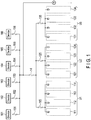
- FIG. 1 is a block diagram showing the structure of a storage cell system according to the present embodiment.
- FIG. 1 shows storage cell modules 111 to 114, 121 to 124 and 131 to 134 having the same structure.
- Four storage cell modules are connected in parallel to form each unit.
- Air circuit breakers (ACBs) 115, 125 and 135 are inserted into the output lines of units U1 to U3, respectively.
- the output terminals of units U1 to U3 are connected in parallel to each other, and are connected to the output terminal of a system power source via an ACB 14.
- loading devices 161 to 166 are connected to the output terminal of the system power source via fuses 151 to 156.
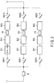
- FIG. 2 is a block diagram specifically showing one of storage cell modules 111 to 114, 121 to 124 and 131 to 134 used for the above storage cell system.
- FIG. 2 shows storage cells B11 to B13, B21 to B23 and B31 to B33 (although each block is explained as a single cell here, as exemplarily shown by B11, each block may be a group of cells formed by connecting storage cells in series), fuses H1, H2 and H3, and relay switches SW11, SW12, SW21, SW22, SW31 and SW32.
- Storage cells B11 to B13, fuse H1 and relay switches SW11 and SW12 are connected in series to form a first cell line.
- Storage cells B21 to B23, fuse H2 and relay switches SW21 and SW22 are connected in series to form a second cell line.
- Storage cells B31 to B33, fuse H3 and relay switches SW31 and SW32 are connected in series to form a third cell line. These first to third cell lines are connected in parallel to each other.
- Fuses H1, H2 and H3 block the circuits when the current flowing in the cell lines is overcurrent.
- Relay switches SW11, SW12, SW21, SW22, SW31 and SW32 are used to disconnect or connect the cell lines for replacement when the abnormality of a storage cell is detected.
- a current-limiting resistor R1 which limits current to a time shorter than that of the ACBs and fuses is connected in series between the parallel circuits of the first to third cell lines and the output terminal of the module.
- FIG. 3 is a characteristic diagram showing the protective coordination characteristics for dealing with the failure of the storage cells used for the storage cell system having the above structure.
- FIG. 3 shows the power restriction line A of the current-limiting resistor R, the power restriction line B of the fuses, and the upper limit and lower limit lines C1 and C2 of the ACB.
- the time required for the current limitation of the current-limiting resistor R is shorter than that of the ACB and fuses within 0.1 seconds.
- the overcurrent caused by backward current is suppressed in a short time before the fuse by the current limitation of the current-limiting resistor R.
- the fuse responds and disconnects the line including the defective cell. In this way, the failure of the module is avoided. Thus, the effect on the other modules is also avoided.
- the storage cell system of the present embodiment having the above structure is capable of certainly preventing sequential failures in the entire system caused by the failure of a storage cell without using a large protection device such as a PCS.
- the present invention is not limited to the embodiments described above, and the constituent elements of the invention can be modified without departing from the spirit and scope of the invention.
- a power source by an electric double layer capacitor or a flywheel can be also realized as a modification of the storage cell system of the above embodiments.
- Various aspects of the invention can also be extracted from any appropriate combination of constituent elements disclosed in the embodiments. Some of the constituent elements disclosed in the embodiments may be deleted, and the constituent elements described in different embodiments may be arbitrarily combined.
Landscapes
- Engineering & Computer Science (AREA)
- Power Engineering (AREA)
- Chemical & Material Sciences (AREA)
- Chemical Kinetics & Catalysis (AREA)
- Electrochemistry (AREA)
- General Chemical & Material Sciences (AREA)
- Manufacturing & Machinery (AREA)
- Microelectronics & Electronic Packaging (AREA)
- Charge And Discharge Circuits For Batteries Or The Like (AREA)
- Battery Mounting, Suspending (AREA)
- Protection Of Static Devices (AREA)
- Emergency Protection Circuit Devices (AREA)
- Secondary Cells (AREA)
Abstract
Description
- Embodiments described herein relate generally to a storage cell system, a storage cell module and a method for operating a storage cell system.
- In a storage cell system, serial circuits each formed by connecting a prescribed number of storage cells in series are connected in parallel to form a storage cell module. Each unit is formed by connecting a prescribed number of storage cell modules in parallel. Outputs of a number of units corresponding to load capacity are linked in parallel and supplied to a load. In this system structure, if a single storage cell fails, and backward current is generated, another storage cell in the same module, another storage cell module or another storage cell unit may sequentially fail.
- As a countermeasure, in general, the defect portion is limited by managing each unit in a power conditioning system (PCS). However, the PCS is large and requires a space in comparison with storage cell units. Thus, the PCS is not suitable for the application in a small space or the management based on each module.
- Apart from the above method, a fuse is connected to each storage cell to protect it from overcurrent. However, in this method, it is not possible to deal with a rapid increase in current in a storage cell having low impedance.
- Patent Literature 1:
JP 2005-323444 A - As described above, in the conventional storage cell system, a PCS is employed as a countermeasure to prevent sequential failures caused in the entire system by the failure of a single storage cell and backward current. However, this countermeasure is insufficient as the PCS is disadvantageous in terms of its size.
- Embodiments described herein aim to provide a storage cell system, a storage cell module and a method for operating a storage cell system, capable of certainly preventing sequential failures in the entire system even if a storage cell fails.
- According to one embodiment, the above problem is solved by a storage cell system. In the storage cell system, cell lines each formed by connecting a prescribed number of storage cells in series are connected in parallel to form a storage cell module. Each unit is formed by connecting a prescribed number of storage cell modules in parallel. Outputs of a number of units corresponding to load capacity are linked in parallel and supplied to a load. Current is limited to an extent that the storage cells are not damaged by interposing a current-limiting resistor in an output line of the storage cell module.
-
-
FIG. 1 is a block diagram showing the structure of a storage cell system according to the present embodiment. -
FIG. 2 is a block diagram showing the specific structure of each storage cell module shown inFIG. 1 . -
FIG. 3 is a characteristic diagram showing the protective coordination characteristics of each storage cell module shown inFIG. 1 . - Mode for Carrying Out the Invention Embodiments will be described below with reference to the accompanying drawings.
-
FIG. 1 is a block diagram showing the structure of a storage cell system according to the present embodiment.FIG. 1 showsstorage cell modules 111 to 114, 121 to 124 and 131 to 134 having the same structure. Four storage cell modules are connected in parallel to form each unit. Air circuit breakers (ACBs) 115, 125 and 135 are inserted into the output lines of units U1 to U3, respectively. The output terminals of units U1 to U3 are connected in parallel to each other, and are connected to the output terminal of a system power source via an ACB 14. For example,loading devices 161 to 166 are connected to the output terminal of the system power source viafuses 151 to 156. -
FIG. 2 is a block diagram specifically showing one ofstorage cell modules 111 to 114, 121 to 124 and 131 to 134 used for the above storage cell system.FIG. 2 shows storage cells B11 to B13, B21 to B23 and B31 to B33 (although each block is explained as a single cell here, as exemplarily shown by B11, each block may be a group of cells formed by connecting storage cells in series), fuses H1, H2 and H3, and relay switches SW11, SW12, SW21, SW22, SW31 and SW32. Storage cells B11 to B13, fuse H1 and relay switches SW11 and SW12 are connected in series to form a first cell line. Storage cells B21 to B23, fuse H2 and relay switches SW21 and SW22 are connected in series to form a second cell line. Storage cells B31 to B33, fuse H3 and relay switches SW31 and SW32 are connected in series to form a third cell line. These first to third cell lines are connected in parallel to each other. - Fuses H1, H2 and H3 block the circuits when the current flowing in the cell lines is overcurrent. Relay switches SW11, SW12, SW21, SW22, SW31 and SW32 are used to disconnect or connect the cell lines for replacement when the abnormality of a storage cell is detected. A current-limiting resistor R1 which limits current to a time shorter than that of the ACBs and fuses is connected in series between the parallel circuits of the first to third cell lines and the output terminal of the module.
- In the above structure, each cell line in the storage cell module is protected by the fuse. The output line of the storage cell module is protected by the current-limiting resistor R1. The output line of each unit is protected by the ACB.
FIG. 3 is a characteristic diagram showing the protective coordination characteristics for dealing with the failure of the storage cells used for the storage cell system having the above structure.FIG. 3 shows the power restriction line A of the current-limiting resistor R, the power restriction line B of the fuses, and the upper limit and lower limit lines C1 and C2 of the ACB. - As shown in
FIG. 3 , the time required for the current limitation of the current-limiting resistor R is shorter than that of the ACB and fuses within 0.1 seconds. Thus, even if a storage cell fails in the module, the overcurrent caused by backward current is suppressed in a short time before the fuse by the current limitation of the current-limiting resistor R. Subsequently, the fuse responds and disconnects the line including the defective cell. In this way, the failure of the module is avoided. Thus, the effect on the other modules is also avoided. - As described above, the storage cell system of the present embodiment having the above structure is capable of certainly preventing sequential failures in the entire system caused by the failure of a storage cell without using a large protection device such as a PCS.
- The present invention is not limited to the embodiments described above, and the constituent elements of the invention can be modified without departing from the spirit and scope of the invention. For example, a power source by an electric double layer capacitor or a flywheel can be also realized as a modification of the storage cell system of the above embodiments. Various aspects of the invention can also be extracted from any appropriate combination of constituent elements disclosed in the embodiments. Some of the constituent elements disclosed in the embodiments may be deleted, and the constituent elements described in different embodiments may be arbitrarily combined.
- 111-114, 121-124, 131-134 . . . Storage cell modules, U1-U3 . . . Storage cell units, 115, 125, 135, 14 . . . Air circuit breakers (ACBs), 151-156 . . . Fuses, 161-166 . . . Loading devices, B11-B13, B21-B23, B31-B33 . . . Storage cells, H1, H2, H3 . . . Fuses, SW11, SW12, SW21, SW22, SW31, SE32 . . . Relay switches
Claims (8)
- A storage cell system in which
cell lines each formed by connecting a prescribed number of storage cells in series are connected in parallel to form a storage cell module,
each unit is formed by connecting a prescribed number of storage cell modules in parallel, and
outputs of a number of units corresponding to load capacity are linked in parallel and supplied to a load, wherein
current is limited by at least interposing a current-limiting resistor in a parallel output line of the storage cell module. - The system of Claim 1, wherein a fuse is interposed in each of the cell lines.
- The system of Claim 1, wherein an air circuit breaker is interposed in a parallel output line of the units.
- The system of Claim 1, wherein the current-limiting resistor is interposed in each of the cell lines.
- A storage cell module in which
cell lines each formed by connecting a prescribed number of storage cells in series are connected in parallel, wherein
current is limited by at least interposing a current-limiting resistor in a parallel output line. - The module of Claim 5, wherein a fuse is interposed in each of the cell lines.
- The module of Claim 5, wherein the current-limiting resistor is interposed in each of the cell lines.
- A method for operating a storage cell system, the method comprising:forming a storage cell module by connecting cell lines in parallel, each of the cell lines formed by connecting a prescribed number of storage cells in series;forming each unit by connecting a prescribed number of storage cell modules in parallel; andlinking outputs of a number of units corresponding to load capacity in parallel and supplying the outputs to a load, whereincurrent is limited by at least interposing a current-limiting resistor in a parallel output line of the storage cell module, andprotective coordination for overcurrent of the storage cells is performed by interposing a fuse in each of the cell lines.
Applications Claiming Priority (1)
| Application Number | Priority Date | Filing Date | Title |
|---|---|---|---|
| PCT/JP2015/067875 WO2016207949A1 (en) | 2015-06-22 | 2015-06-22 | Storage cell system, storage cell module, and method for operating storage cell system |
Publications (3)
| Publication Number | Publication Date |
|---|---|
| EP3312966A1 true EP3312966A1 (en) | 2018-04-25 |
| EP3312966A4 EP3312966A4 (en) | 2018-12-05 |
| EP3312966B1 EP3312966B1 (en) | 2019-11-06 |
Family
ID=57584821
Family Applications (1)
| Application Number | Title | Priority Date | Filing Date |
|---|---|---|---|
| EP15896272.0A Active EP3312966B1 (en) | 2015-06-22 | 2015-06-22 | Storage cell system, storage cell module, and method for operating storage cell system |
Country Status (5)
| Country | Link |
|---|---|
| US (1) | US10109841B2 (en) |
| EP (1) | EP3312966B1 (en) |
| JP (2) | JP6226408B2 (en) |
| AU (1) | AU2015399888B2 (en) |
| WO (1) | WO2016207949A1 (en) |
Families Citing this family (6)
| Publication number | Priority date | Publication date | Assignee | Title |
|---|---|---|---|---|
| EP3320552B1 (en) * | 2015-08-28 | 2019-05-01 | Siemens Aktiengesellschaft | Capacitor aggregate, high voltage direct current transmission |
| CN109177814A (en) * | 2018-09-30 | 2019-01-11 | 北京长城华冠汽车科技股份有限公司 | Electrification switching system, method and the electric car of electric automobile battery box |
| JP7336890B2 (en) * | 2019-06-24 | 2023-09-01 | 古河電池株式会社 | power storage device |
| JP7191873B2 (en) * | 2020-01-17 | 2022-12-19 | 株式会社東芝 | Charge/discharge control device, charge/discharge system, charge/discharge control method, and charge/discharge control program |
| CN111987791B (en) | 2020-08-18 | 2024-05-24 | 百度在线网络技术(北京)有限公司 | Battery module control device and method, power supply equipment and system |
| WO2022253407A1 (en) | 2021-05-31 | 2022-12-08 | Hitachi Energy Switzerland Ag | Module for large scale energy storage |
Family Cites Families (16)
| Publication number | Priority date | Publication date | Assignee | Title |
|---|---|---|---|---|
| JP2591814Y2 (en) * | 1992-05-22 | 1999-03-10 | 株式会社ニコン | External power supply |
| JP3987178B2 (en) * | 1997-12-09 | 2007-10-03 | 日置電機株式会社 | Battery pack deterioration determination method and battery pack deterioration determination device |
| JP4120540B2 (en) | 2003-09-08 | 2008-07-16 | 富士電機システムズ株式会社 | DC feeding network protection method and DC feeding network protection system |
| JP4120618B2 (en) | 2004-05-07 | 2008-07-16 | 富士電機システムズ株式会社 | DC feeding network protection system |
| JP5017009B2 (en) * | 2007-07-30 | 2012-09-05 | 株式会社東芝 | Parallel connection power storage system |
| JP2010239045A (en) * | 2009-03-31 | 2010-10-21 | Sharp Corp | Solar power generation system and power line for solar power generation system |
| US9005788B2 (en) | 2009-07-06 | 2015-04-14 | Amperex Technology Limited | Management scheme for multiple battery cells |
| EP2717424B1 (en) * | 2011-05-31 | 2018-02-21 | LG Chem, Ltd. | Apparatus for leveling voltage for connecting unit racks for storing power, and system for storing power comprising same |
| JP5748689B2 (en) * | 2012-02-28 | 2015-07-15 | 三菱重工業株式会社 | Battery system |
| US9539963B2 (en) | 2012-03-23 | 2017-01-10 | Kabushiki Kaisha Toshiba | Battery system and method of operating the battery system |
| KR101648239B1 (en) * | 2012-06-29 | 2016-08-12 | 삼성에스디아이 주식회사 | Energy storage device and method for decreasing rush current |
| JP6036137B2 (en) * | 2012-10-09 | 2016-11-30 | 横河電機株式会社 | Battery storage structure and explosion-proof equipment |
| JP5887260B2 (en) * | 2012-12-21 | 2016-03-16 | 東芝三菱電機産業システム株式会社 | Storage battery remaining amount management device |
| JP2014236561A (en) * | 2013-05-31 | 2014-12-15 | 三菱重工業株式会社 | Secondary battery system, control method thereof, and power generation system |
| JP2014239630A (en) * | 2013-06-10 | 2014-12-18 | 株式会社東芝 | Storage battery device and control program |
| JP6427743B2 (en) | 2013-11-19 | 2018-11-28 | エリーパワー株式会社 | Storage battery unit, overcurrent control method and program |
-
2015
- 2015-06-22 AU AU2015399888A patent/AU2015399888B2/en active Active
- 2015-06-22 JP JP2016559665A patent/JP6226408B2/en active Active
- 2015-06-22 EP EP15896272.0A patent/EP3312966B1/en active Active
- 2015-06-22 WO PCT/JP2015/067875 patent/WO2016207949A1/en not_active Ceased
-
2017
- 2017-08-09 JP JP2017154135A patent/JP2018011502A/en active Pending
- 2017-12-12 US US15/838,530 patent/US10109841B2/en active Active
Also Published As
| Publication number | Publication date |
|---|---|
| AU2015399888A1 (en) | 2018-01-18 |
| JP2018011502A (en) | 2018-01-18 |
| WO2016207949A1 (en) | 2016-12-29 |
| AU2015399888B2 (en) | 2018-05-10 |
| JPWO2016207949A1 (en) | 2017-06-29 |
| EP3312966A4 (en) | 2018-12-05 |
| EP3312966B1 (en) | 2019-11-06 |
| JP6226408B2 (en) | 2017-11-08 |
| US10109841B2 (en) | 2018-10-23 |
| US20180102529A1 (en) | 2018-04-12 |
Similar Documents
| Publication | Publication Date | Title |
|---|---|---|
| EP3312966A1 (en) | Storage cell system, storage cell module, and method for operating storage cell system | |
| US8654495B2 (en) | Battery energy storage system with short circuit protection, and method | |
| KR101062101B1 (en) | Submarine DC Network with High Power Energy Storage Batteries | |
| EP2608347A2 (en) | Electric energy storage system and method of maintaining the same | |
| CN103367689A (en) | Battery pack and battery system | |
| US9461456B2 (en) | Integrated switchboard for a modular data center | |
| US9923414B2 (en) | System for redundant power supply to a data center | |
| EP2846387B1 (en) | Apparatus and method for controlling fuel cell system using sub-power conditioning system | |
| EP2304825B1 (en) | A battery unit arrangement for high voltage applications, connector and disconnector arrangement and method | |
| CN104838577B (en) | Passive circuits for improved failure mode handling in power electronics modules | |
| KR102151107B1 (en) | Protection and distribution board for energy storage system | |
| US9985321B2 (en) | Battery system | |
| CN103891076A (en) | Power distribution apparatus for separate electrical over current and short circuit protection | |
| JP2014182679A (en) | Protection circuit | |
| US9153956B2 (en) | Test device for power engineering equipment and method for manufacturing a test device for power engineering equipment | |
| US10931098B2 (en) | Energy supply circuit, electrical drive system, and missile comprising an electric drive system | |
| JP6694554B2 (en) | Inductive element protection | |
| CN107846008B (en) | A wiring device | |
| CN118872176A (en) | Battery Power Supply Architecture | |
| KR20260006774A (en) | Protective switchboards in energy storage systems | |
| CN117715800A (en) | Energy supply module and energy supply management system | |
| CN120454222A (en) | Method and device for controlling high-voltage energy storage system to enter maintenance state | |
| JP2014239611A (en) | Battery module and battery pack system | |
| CN110999017A (en) | Electric energy storage system for aircraft | |
| JP2014041809A (en) | Battery cell unit formed by parallel connection of two secondary battery cells and two fuses and capable of being independently disconnected |
Legal Events
| Date | Code | Title | Description |
|---|---|---|---|
| STAA | Information on the status of an ep patent application or granted ep patent |
Free format text: STATUS: THE INTERNATIONAL PUBLICATION HAS BEEN MADE |
|
| PUAI | Public reference made under article 153(3) epc to a published international application that has entered the european phase |
Free format text: ORIGINAL CODE: 0009012 |
|
| STAA | Information on the status of an ep patent application or granted ep patent |
Free format text: STATUS: REQUEST FOR EXAMINATION WAS MADE |
|
| 17P | Request for examination filed |
Effective date: 20171213 |
|
| AK | Designated contracting states |
Kind code of ref document: A1 Designated state(s): AL AT BE BG CH CY CZ DE DK EE ES FI FR GB GR HR HU IE IS IT LI LT LU LV MC MK MT NL NO PL PT RO RS SE SI SK SM TR |
|
| AX | Request for extension of the european patent |
Extension state: BA ME |
|
| DAV | Request for validation of the european patent (deleted) | ||
| DAX | Request for extension of the european patent (deleted) | ||
| A4 | Supplementary search report drawn up and despatched |
Effective date: 20181026 |
|
| RIC1 | Information provided on ipc code assigned before grant |
Ipc: H01M 10/42 20060101ALI20181022BHEP Ipc: H01M 2/34 20060101ALI20181022BHEP Ipc: H01M 2/20 20060101ALN20181022BHEP Ipc: H02J 7/00 20060101AFI20181022BHEP |
|
| RIC1 | Information provided on ipc code assigned before grant |
Ipc: H01M 2/20 20060101ALI20190320BHEP Ipc: H01M 2/34 20060101ALI20190320BHEP Ipc: H01M 10/42 20060101ALI20190320BHEP Ipc: H02J 7/00 20060101AFI20190320BHEP |
|
| GRAP | Despatch of communication of intention to grant a patent |
Free format text: ORIGINAL CODE: EPIDOSNIGR1 |
|
| STAA | Information on the status of an ep patent application or granted ep patent |
Free format text: STATUS: GRANT OF PATENT IS INTENDED |
|
| INTG | Intention to grant announced |
Effective date: 20190606 |
|
| GRAS | Grant fee paid |
Free format text: ORIGINAL CODE: EPIDOSNIGR3 |
|
| GRAA | (expected) grant |
Free format text: ORIGINAL CODE: 0009210 |
|
| STAA | Information on the status of an ep patent application or granted ep patent |
Free format text: STATUS: THE PATENT HAS BEEN GRANTED |
|
| AK | Designated contracting states |
Kind code of ref document: B1 Designated state(s): AL AT BE BG CH CY CZ DE DK EE ES FI FR GB GR HR HU IE IS IT LI LT LU LV MC MK MT NL NO PL PT RO RS SE SI SK SM TR |
|
| REG | Reference to a national code |
Ref country code: GB Ref legal event code: FG4D |
|
| REG | Reference to a national code |
Ref country code: CH Ref legal event code: EP Ref country code: AT Ref legal event code: REF Ref document number: 1200115 Country of ref document: AT Kind code of ref document: T Effective date: 20191115 |
|
| REG | Reference to a national code |
Ref country code: IE Ref legal event code: FG4D |
|
| REG | Reference to a national code |
Ref country code: DE Ref legal event code: R096 Ref document number: 602015041443 Country of ref document: DE |
|
| REG | Reference to a national code |
Ref country code: SE Ref legal event code: TRGR |
|
| REG | Reference to a national code |
Ref country code: NL Ref legal event code: MP Effective date: 20191106 |
|
| REG | Reference to a national code |
Ref country code: LT Ref legal event code: MG4D |
|
| PG25 | Lapsed in a contracting state [announced via postgrant information from national office to epo] |
Ref country code: PT Free format text: LAPSE BECAUSE OF FAILURE TO SUBMIT A TRANSLATION OF THE DESCRIPTION OR TO PAY THE FEE WITHIN THE PRESCRIBED TIME-LIMIT Effective date: 20200306 Ref country code: NL Free format text: LAPSE BECAUSE OF FAILURE TO SUBMIT A TRANSLATION OF THE DESCRIPTION OR TO PAY THE FEE WITHIN THE PRESCRIBED TIME-LIMIT Effective date: 20191106 Ref country code: NO Free format text: LAPSE BECAUSE OF FAILURE TO SUBMIT A TRANSLATION OF THE DESCRIPTION OR TO PAY THE FEE WITHIN THE PRESCRIBED TIME-LIMIT Effective date: 20200206 Ref country code: GR Free format text: LAPSE BECAUSE OF FAILURE TO SUBMIT A TRANSLATION OF THE DESCRIPTION OR TO PAY THE FEE WITHIN THE PRESCRIBED TIME-LIMIT Effective date: 20200207 Ref country code: BG Free format text: LAPSE BECAUSE OF FAILURE TO SUBMIT A TRANSLATION OF THE DESCRIPTION OR TO PAY THE FEE WITHIN THE PRESCRIBED TIME-LIMIT Effective date: 20200206 Ref country code: PL Free format text: LAPSE BECAUSE OF FAILURE TO SUBMIT A TRANSLATION OF THE DESCRIPTION OR TO PAY THE FEE WITHIN THE PRESCRIBED TIME-LIMIT Effective date: 20191106 Ref country code: FI Free format text: LAPSE BECAUSE OF FAILURE TO SUBMIT A TRANSLATION OF THE DESCRIPTION OR TO PAY THE FEE WITHIN THE PRESCRIBED TIME-LIMIT Effective date: 20191106 Ref country code: LT Free format text: LAPSE BECAUSE OF FAILURE TO SUBMIT A TRANSLATION OF THE DESCRIPTION OR TO PAY THE FEE WITHIN THE PRESCRIBED TIME-LIMIT Effective date: 20191106 Ref country code: LV Free format text: LAPSE BECAUSE OF FAILURE TO SUBMIT A TRANSLATION OF THE DESCRIPTION OR TO PAY THE FEE WITHIN THE PRESCRIBED TIME-LIMIT Effective date: 20191106 |
|
| PG25 | Lapsed in a contracting state [announced via postgrant information from national office to epo] |
Ref country code: HR Free format text: LAPSE BECAUSE OF FAILURE TO SUBMIT A TRANSLATION OF THE DESCRIPTION OR TO PAY THE FEE WITHIN THE PRESCRIBED TIME-LIMIT Effective date: 20191106 Ref country code: RS Free format text: LAPSE BECAUSE OF FAILURE TO SUBMIT A TRANSLATION OF THE DESCRIPTION OR TO PAY THE FEE WITHIN THE PRESCRIBED TIME-LIMIT Effective date: 20191106 Ref country code: IS Free format text: LAPSE BECAUSE OF FAILURE TO SUBMIT A TRANSLATION OF THE DESCRIPTION OR TO PAY THE FEE WITHIN THE PRESCRIBED TIME-LIMIT Effective date: 20200306 |
|
| PG25 | Lapsed in a contracting state [announced via postgrant information from national office to epo] |
Ref country code: AL Free format text: LAPSE BECAUSE OF FAILURE TO SUBMIT A TRANSLATION OF THE DESCRIPTION OR TO PAY THE FEE WITHIN THE PRESCRIBED TIME-LIMIT Effective date: 20191106 |
|
| PG25 | Lapsed in a contracting state [announced via postgrant information from national office to epo] |
Ref country code: RO Free format text: LAPSE BECAUSE OF FAILURE TO SUBMIT A TRANSLATION OF THE DESCRIPTION OR TO PAY THE FEE WITHIN THE PRESCRIBED TIME-LIMIT Effective date: 20191106 Ref country code: ES Free format text: LAPSE BECAUSE OF FAILURE TO SUBMIT A TRANSLATION OF THE DESCRIPTION OR TO PAY THE FEE WITHIN THE PRESCRIBED TIME-LIMIT Effective date: 20191106 Ref country code: CZ Free format text: LAPSE BECAUSE OF FAILURE TO SUBMIT A TRANSLATION OF THE DESCRIPTION OR TO PAY THE FEE WITHIN THE PRESCRIBED TIME-LIMIT Effective date: 20191106 Ref country code: DK Free format text: LAPSE BECAUSE OF FAILURE TO SUBMIT A TRANSLATION OF THE DESCRIPTION OR TO PAY THE FEE WITHIN THE PRESCRIBED TIME-LIMIT Effective date: 20191106 Ref country code: EE Free format text: LAPSE BECAUSE OF FAILURE TO SUBMIT A TRANSLATION OF THE DESCRIPTION OR TO PAY THE FEE WITHIN THE PRESCRIBED TIME-LIMIT Effective date: 20191106 |
|
| REG | Reference to a national code |
Ref country code: DE Ref legal event code: R097 Ref document number: 602015041443 Country of ref document: DE |
|
| REG | Reference to a national code |
Ref country code: AT Ref legal event code: MK05 Ref document number: 1200115 Country of ref document: AT Kind code of ref document: T Effective date: 20191106 |
|
| PG25 | Lapsed in a contracting state [announced via postgrant information from national office to epo] |
Ref country code: SM Free format text: LAPSE BECAUSE OF FAILURE TO SUBMIT A TRANSLATION OF THE DESCRIPTION OR TO PAY THE FEE WITHIN THE PRESCRIBED TIME-LIMIT Effective date: 20191106 Ref country code: SK Free format text: LAPSE BECAUSE OF FAILURE TO SUBMIT A TRANSLATION OF THE DESCRIPTION OR TO PAY THE FEE WITHIN THE PRESCRIBED TIME-LIMIT Effective date: 20191106 |
|
| PLBE | No opposition filed within time limit |
Free format text: ORIGINAL CODE: 0009261 |
|
| STAA | Information on the status of an ep patent application or granted ep patent |
Free format text: STATUS: NO OPPOSITION FILED WITHIN TIME LIMIT |
|
| 26N | No opposition filed |
Effective date: 20200807 |
|
| PG25 | Lapsed in a contracting state [announced via postgrant information from national office to epo] |
Ref country code: SI Free format text: LAPSE BECAUSE OF FAILURE TO SUBMIT A TRANSLATION OF THE DESCRIPTION OR TO PAY THE FEE WITHIN THE PRESCRIBED TIME-LIMIT Effective date: 20191106 Ref country code: AT Free format text: LAPSE BECAUSE OF FAILURE TO SUBMIT A TRANSLATION OF THE DESCRIPTION OR TO PAY THE FEE WITHIN THE PRESCRIBED TIME-LIMIT Effective date: 20191106 |
|
| PG25 | Lapsed in a contracting state [announced via postgrant information from national office to epo] |
Ref country code: MC Free format text: LAPSE BECAUSE OF FAILURE TO SUBMIT A TRANSLATION OF THE DESCRIPTION OR TO PAY THE FEE WITHIN THE PRESCRIBED TIME-LIMIT Effective date: 20191106 Ref country code: IT Free format text: LAPSE BECAUSE OF FAILURE TO SUBMIT A TRANSLATION OF THE DESCRIPTION OR TO PAY THE FEE WITHIN THE PRESCRIBED TIME-LIMIT Effective date: 20191106 |
|
| REG | Reference to a national code |
Ref country code: CH Ref legal event code: PL |
|
| PG25 | Lapsed in a contracting state [announced via postgrant information from national office to epo] |
Ref country code: LU Free format text: LAPSE BECAUSE OF NON-PAYMENT OF DUE FEES Effective date: 20200622 |
|
| REG | Reference to a national code |
Ref country code: BE Ref legal event code: MM Effective date: 20200630 |
|
| PG25 | Lapsed in a contracting state [announced via postgrant information from national office to epo] |
Ref country code: IE Free format text: LAPSE BECAUSE OF NON-PAYMENT OF DUE FEES Effective date: 20200622 Ref country code: CH Free format text: LAPSE BECAUSE OF NON-PAYMENT OF DUE FEES Effective date: 20200630 Ref country code: LI Free format text: LAPSE BECAUSE OF NON-PAYMENT OF DUE FEES Effective date: 20200630 |
|
| PG25 | Lapsed in a contracting state [announced via postgrant information from national office to epo] |
Ref country code: BE Free format text: LAPSE BECAUSE OF NON-PAYMENT OF DUE FEES Effective date: 20200630 |
|
| PG25 | Lapsed in a contracting state [announced via postgrant information from national office to epo] |
Ref country code: TR Free format text: LAPSE BECAUSE OF FAILURE TO SUBMIT A TRANSLATION OF THE DESCRIPTION OR TO PAY THE FEE WITHIN THE PRESCRIBED TIME-LIMIT Effective date: 20191106 Ref country code: MT Free format text: LAPSE BECAUSE OF FAILURE TO SUBMIT A TRANSLATION OF THE DESCRIPTION OR TO PAY THE FEE WITHIN THE PRESCRIBED TIME-LIMIT Effective date: 20191106 Ref country code: CY Free format text: LAPSE BECAUSE OF FAILURE TO SUBMIT A TRANSLATION OF THE DESCRIPTION OR TO PAY THE FEE WITHIN THE PRESCRIBED TIME-LIMIT Effective date: 20191106 |
|
| PG25 | Lapsed in a contracting state [announced via postgrant information from national office to epo] |
Ref country code: MK Free format text: LAPSE BECAUSE OF FAILURE TO SUBMIT A TRANSLATION OF THE DESCRIPTION OR TO PAY THE FEE WITHIN THE PRESCRIBED TIME-LIMIT Effective date: 20191106 |
|
| PGFP | Annual fee paid to national office [announced via postgrant information from national office to epo] |
Ref country code: SE Payment date: 20250310 Year of fee payment: 11 |
|
| PGFP | Annual fee paid to national office [announced via postgrant information from national office to epo] |
Ref country code: DE Payment date: 20250402 Year of fee payment: 11 |
|
| PGFP | Annual fee paid to national office [announced via postgrant information from national office to epo] |
Ref country code: GB Payment date: 20250401 Year of fee payment: 11 |
|
| PGFP | Annual fee paid to national office [announced via postgrant information from national office to epo] |
Ref country code: FR Payment date: 20250508 Year of fee payment: 11 |